JP6332758B2 - Illumination optical unit for EUV projection lithography - Google Patents
Illumination optical unit for EUV projection lithography Download PDFInfo
- Publication number
- JP6332758B2 JP6332758B2 JP2015511982A JP2015511982A JP6332758B2 JP 6332758 B2 JP6332758 B2 JP 6332758B2 JP 2015511982 A JP2015511982 A JP 2015511982A JP 2015511982 A JP2015511982 A JP 2015511982A JP 6332758 B2 JP6332758 B2 JP 6332758B2
- Authority
- JP
- Japan
- Prior art keywords
- mirror
- individual
- illumination
- group
- facet
- Prior art date
- Legal status (The legal status is an assumption and is not a legal conclusion. Google has not performed a legal analysis and makes no representation as to the accuracy of the status listed.)
- Active
Links
Images


Classifications
-
- G—PHYSICS
- G03—PHOTOGRAPHY; CINEMATOGRAPHY; ANALOGOUS TECHNIQUES USING WAVES OTHER THAN OPTICAL WAVES; ELECTROGRAPHY; HOLOGRAPHY
- G03F—PHOTOMECHANICAL PRODUCTION OF TEXTURED OR PATTERNED SURFACES, e.g. FOR PRINTING, FOR PROCESSING OF SEMICONDUCTOR DEVICES; MATERIALS THEREFOR; ORIGINALS THEREFOR; APPARATUS SPECIALLY ADAPTED THEREFOR
- G03F7/00—Photomechanical, e.g. photolithographic, production of textured or patterned surfaces, e.g. printing surfaces; Materials therefor, e.g. comprising photoresists; Apparatus specially adapted therefor
- G03F7/70—Microphotolithographic exposure; Apparatus therefor
- G03F7/70058—Mask illumination systems
- G03F7/70091—Illumination settings, i.e. intensity distribution in the pupil plane or angular distribution in the field plane; On-axis or off-axis settings, e.g. annular, dipole or quadrupole settings; Partial coherence control, i.e. sigma or numerical aperture [NA]
- G03F7/70116—Off-axis setting using a programmable means, e.g. liquid crystal display [LCD], digital micromirror device [DMD] or pupil facets
-
- G—PHYSICS
- G02—OPTICS
- G02B—OPTICAL ELEMENTS, SYSTEMS OR APPARATUS
- G02B26/00—Optical devices or arrangements for the control of light using movable or deformable optical elements
- G02B26/08—Optical devices or arrangements for the control of light using movable or deformable optical elements for controlling the direction of light
- G02B26/0816—Optical devices or arrangements for the control of light using movable or deformable optical elements for controlling the direction of light by means of one or more reflecting elements
- G02B26/0833—Optical devices or arrangements for the control of light using movable or deformable optical elements for controlling the direction of light by means of one or more reflecting elements the reflecting element being a micromechanical device, e.g. a MEMS mirror, DMD
-
- G—PHYSICS
- G02—OPTICS
- G02B—OPTICAL ELEMENTS, SYSTEMS OR APPARATUS
- G02B5/00—Optical elements other than lenses
- G02B5/08—Mirrors
- G02B5/0891—Ultraviolet [UV] mirrors
-
- G—PHYSICS
- G03—PHOTOGRAPHY; CINEMATOGRAPHY; ANALOGOUS TECHNIQUES USING WAVES OTHER THAN OPTICAL WAVES; ELECTROGRAPHY; HOLOGRAPHY
- G03F—PHOTOMECHANICAL PRODUCTION OF TEXTURED OR PATTERNED SURFACES, e.g. FOR PRINTING, FOR PROCESSING OF SEMICONDUCTOR DEVICES; MATERIALS THEREFOR; ORIGINALS THEREFOR; APPARATUS SPECIALLY ADAPTED THEREFOR
- G03F7/00—Photomechanical, e.g. photolithographic, production of textured or patterned surfaces, e.g. printing surfaces; Materials therefor, e.g. comprising photoresists; Apparatus specially adapted therefor
- G03F7/70—Microphotolithographic exposure; Apparatus therefor
- G03F7/70058—Mask illumination systems
- G03F7/70075—Homogenization of illumination intensity in the mask plane by using an integrator, e.g. fly's eye lens, facet mirror or glass rod, by using a diffusing optical element or by beam deflection
-
- G—PHYSICS
- G03—PHOTOGRAPHY; CINEMATOGRAPHY; ANALOGOUS TECHNIQUES USING WAVES OTHER THAN OPTICAL WAVES; ELECTROGRAPHY; HOLOGRAPHY
- G03F—PHOTOMECHANICAL PRODUCTION OF TEXTURED OR PATTERNED SURFACES, e.g. FOR PRINTING, FOR PROCESSING OF SEMICONDUCTOR DEVICES; MATERIALS THEREFOR; ORIGINALS THEREFOR; APPARATUS SPECIALLY ADAPTED THEREFOR
- G03F7/00—Photomechanical, e.g. photolithographic, production of textured or patterned surfaces, e.g. printing surfaces; Materials therefor, e.g. comprising photoresists; Apparatus specially adapted therefor
- G03F7/70—Microphotolithographic exposure; Apparatus therefor
- G03F7/70058—Mask illumination systems
- G03F7/70083—Non-homogeneous intensity distribution in the mask plane
-
- G—PHYSICS
- G03—PHOTOGRAPHY; CINEMATOGRAPHY; ANALOGOUS TECHNIQUES USING WAVES OTHER THAN OPTICAL WAVES; ELECTROGRAPHY; HOLOGRAPHY
- G03F—PHOTOMECHANICAL PRODUCTION OF TEXTURED OR PATTERNED SURFACES, e.g. FOR PRINTING, FOR PROCESSING OF SEMICONDUCTOR DEVICES; MATERIALS THEREFOR; ORIGINALS THEREFOR; APPARATUS SPECIALLY ADAPTED THEREFOR
- G03F7/00—Photomechanical, e.g. photolithographic, production of textured or patterned surfaces, e.g. printing surfaces; Materials therefor, e.g. comprising photoresists; Apparatus specially adapted therefor
- G03F7/70—Microphotolithographic exposure; Apparatus therefor
- G03F7/70058—Mask illumination systems
- G03F7/702—Reflective illumination, i.e. reflective optical elements other than folding mirrors, e.g. extreme ultraviolet [EUV] illumination systems
Description
ドイツ特許出願DE 10 2012 208 064.3の内容が引用によって組み込まれている。
The content of the German
本発明は、リソグラフィマスクを配置することができる物体視野に照明光を案内するためのEUV投影リソグラフィのための照明光学ユニットに関する。これに加えて、本発明は、そのような照明光学ユニットと物体視野を像視野に結像するための投影光学ユニットとを有する照明系に関する。更に、本発明は、そのような照明系を有する投影露光装置、そのような投影露光装置を用いて微細構造化又はナノ構造化構成要素、特に半導体チップを生成する方法、及びこうして生成された微細構造化又はナノ構造化構成要素に関する。 The present invention relates to an illumination optical unit for EUV projection lithography for guiding illumination light into an object field in which a lithographic mask can be arranged. In addition, the present invention relates to an illumination system having such an illumination optical unit and a projection optical unit for forming an object field into an image field. Furthermore, the present invention provides a projection exposure apparatus having such an illumination system, a method for producing a microstructured or nanostructured component, in particular a semiconductor chip, using such a projection exposure apparatus, and the fineness thus produced. It relates to structured or nanostructured components.
冒頭に示したタイプの照明光学ユニットは、US 2011/0001947 A1から公知である。 An illumination optical unit of the type indicated at the beginning is known from US 2011/0001947 A1.
本発明の目的は、異なる照明幾何学形状又は照明設定を設定するときの柔軟性が高められるような冒頭に示したタイプの照明光学ユニットを開発することである。 The object of the present invention is to develop an illumination optical unit of the type indicated at the outset so that the flexibility in setting different illumination geometries or illumination settings is increased.
本発明により、この目的は、リソグラフィマスクを配置することができる物体視野に照明光を案内するためのEUV投影リソグラフィのための照明光学ユニットであって、
少なくとも2つの傾斜位置の間で切り換えることができ、照明光部分ビームを前記物体視野に案内するための個々のミラー照明チャネルを与える多数の個々のミラーを含む第1のファセットミラーを有し、
前記照明光のビーム経路内で前記第1のファセットミラーの下流に配置され、かつ群ミラー照明チャネルを通じた前記物体視野内への該第1のファセットミラーの前記個々のミラーの群の結像にそれぞれ寄与する複数のファセットを有する第2のファセットミラーであって、該個々のミラー群の該像が、該物体視野内で互いの上に重ね合わされる前記第2のファセットミラーを有し、
前記個々のミラーの少なくとも一部が、該個々のミラーのそれぞれの前記傾斜位置に応じて少なくとも1つの専用群ミラー照明チャネルを通じて少なくとも1つの専用の第2のファセットにそれぞれ関連付けることができる前記個々のミラー群のうちの少なくとも2つの異なる群に属する、
ことを特徴とする照明光学ユニットによって達成することができる。
According to the invention, this object is an illumination optical unit for EUV projection lithography for guiding illumination light into an object field in which a lithographic mask can be arranged,
A first facet mirror comprising a number of individual mirrors that can be switched between at least two tilt positions and that provide individual mirror illumination channels for guiding the illumination light partial beam into the object field;
For imaging the group of the individual mirrors of the first facet mirror arranged in the beam path of the illumination light downstream of the first facet mirror and into the object field through a group mirror illumination channel A second facet mirror having a plurality of facets each contributing, wherein the images of the individual mirror groups are superimposed on each other in the object field;
At least a portion of the individual mirrors can each be associated with at least one dedicated second facet through at least one dedicated group mirror illumination channel depending on the tilt position of each of the individual mirrors. Belong to at least two different groups of mirrors,
This can be achieved by an illumination optical unit characterized in that.
本発明は、各個々のミラーが厳密に1つの個々のミラー群だけに関連付けられた特定の個々のミラー群への第1のファセットミラーの全ての個々のミラーの固定された割り当てを指示することから解放される。本発明による照明光学ユニットでは、個々のミラーの傾斜は、個々のミラー照明チャネルを通じて関連付けられた第2のファセットの間の変更をもたらすことができるだけではなく、少なくとも1つの群照明チャネルを通じて少なくとも1つの第2のファセットに関連付けられたそれぞれ1つの個々のミラー群への個々のミラーのグループ割り当てを変更することができる。個々のミラーの傾斜位置に応じて、1つの同じ個々のミラー群をそれぞれ1つの群照明チャネルを通じて異なる第2のファセットに関連付けることができる。個々のミラーの少なくとも一部が、少なくとも2つの異なる個々のミラー群に属することができることの結果として、専用群ミラー照明チャネルを通じて専用の第2のファセットにそれぞれ関連付けられた第1のファセットミラー内の所定の個数の個々のミラーの場合に、従来技術のグループ割り当ての場合に可能であったものよりも遥かに多数の個々のミラー群を形成することができる。従って、所定の個数の個々のミラーを有する第1のファセットミラーを用いて、それぞれの群ミラー照明チャネルを通じて遙かに多数の第2のファセットを照明することができる。それに応じて、原理的に第2のファセットミラーのファセットを通じて照明視野内に個々のミラー群を結像することによって得ることができる照明角度分布の個数及び従って利用可能な照明幾何学形状又は照明設定の個数の増加がある。それとは逆に、より少数の個々のミラーを有する第1のファセットミラーを用いて、所定の個数の必要とされる照明角度分布を得ることができる。第2のファセットミラーのファセットは、個々に又は照明光学ユニットのその後の構成要素と相互作用して、第1のファセットミラーのそれぞれの個々のミラー群を照明視野に結像することに寄与することができる。群ミラー照明チャネルは、第2のファセットミラーの関連付けられたファセットを通じての結像の結果として全体の照明視野を照明する上で互いに相補し合う個々のミラー群の全ての個々のミラー照明チャネルの総計である。個々のミラー群は、物体視野が配置されるか又は物体視野と一致する照明視野の原像であると考えることができる。これらの原像は、それぞれ実質的に同じアスペクト比を有する。個々のミラー群もまた、それぞれ実質的に同じアスペクト比を有する。それぞれの個々のミラー群を物体視野に結像するときに個々のミラーの傾斜位置に依存するビーム幾何学形状の変化の結果として発生するアスペクト比の差は、本明細書では考慮しないままに留める。照明視野の照明は、次に、照明視野内での原像の重ね合わせを構成し、原像は、いかなる場合にも物体視野内で一致する。異なる個々のミラー群は、同じ個々のミラーで構成されない個々のミラー群である。すなわち、異なる個々のミラー群の場合に、両方の個々のミラー群に同時に属さない少なくとも1つの個々のミラーが常に存在する。既に上述したように、1つの同じ個々のミラー群は、傾斜位置に依存して異なる第2のファセットに関連付けることができる。それぞれの個々のミラー群を形成するための個々のミラーの割り当て及びそれぞれの第2のファセットへのそれぞれの個々のミラー群の割り当ては、それぞれ形成される個々のミラー群に属する個々のミラーの対応する位置又はスイッチ位置を指定することによってもたらされる。 The present invention dictates the fixed assignment of all individual mirrors of the first facet mirror to a particular individual mirror group in which each individual mirror is associated with exactly one individual mirror group Released from. In the illumination optical unit according to the invention, the tilt of the individual mirrors can not only bring about a change between the second facets associated through the individual mirror illumination channels, but also at least one through the at least one group illumination channel. The group assignment of individual mirrors to each one individual mirror group associated with the second facet can be changed. Depending on the tilt position of the individual mirrors, one and the same individual mirror group can each be associated with a different second facet through one group illumination channel. As a result of that at least some of the individual mirrors can belong to at least two different individual mirror groups, in the first facet mirror respectively associated with a dedicated second facet through a dedicated group mirror illumination channel. For a given number of individual mirrors, a much larger number of individual mirror groups can be formed than was possible with the prior art group assignment. Thus, a first facet mirror having a predetermined number of individual mirrors can be used to illuminate a much larger number of second facets through each group mirror illumination channel. Accordingly, the number of illumination angle distributions which can be obtained in principle by imaging individual mirror groups in the illumination field through the facets of the second facet mirror and thus the illumination geometry or illumination settings available. There is an increase in the number of Conversely, a first facet mirror having a smaller number of individual mirrors can be used to obtain a predetermined number of required illumination angle distributions. The facets of the second facet mirror contribute to imaging each individual mirror group of the first facet mirror in the illumination field, either individually or interacting with subsequent components of the illumination optical unit. Can do. The group mirror illumination channel is the sum of all individual mirror illumination channels of the individual mirror group that complement each other in illuminating the entire illumination field as a result of imaging through the associated facet of the second facet mirror. It is. Each group of mirrors can be considered the original image of the illumination field where the object field is located or coincides with the object field. Each of these original images has substantially the same aspect ratio. Each individual mirror group also has substantially the same aspect ratio. Differences in aspect ratio that occur as a result of changes in beam geometry that depend on the tilt position of the individual mirrors when each individual mirror group is imaged in the object field are not considered here. . Illumination of the illumination field then constitutes a superposition of the original images in the illumination field, which in any case coincides in the object field. Different individual mirror groups are individual mirror groups that are not composed of the same individual mirror. That is, in the case of different individual mirror groups, there is always at least one individual mirror that does not belong to both individual mirror groups simultaneously. As already mentioned above, one and the same individual mirror group can be associated with different second facets depending on the tilt position. The assignment of individual mirrors to form each individual mirror group and the assignment of each individual mirror group to each second facet is a correspondence of the individual mirrors belonging to the respective individual mirror group to be formed. This is done by specifying a position or switch position.
第1のファセットミラーの個々のミラーのうちの過半数が、専用群ミラー照明チャネルを通じて専用の第2のファセットにそれぞれ関連付けられた個々のミラー群のうちの少なくとも2つに属する割り当ては、特に高い照明柔軟性に導くものである。 Allocations in which the majority of the individual mirrors of the first facet mirror belong to at least two of the individual mirror groups each associated with a dedicated second facet through a dedicated group mirror illumination channel are particularly high illumination It leads to flexibility.
第1のファセットミラーの個々のミラーの少なくとも一部が、専用群ミラー照明チャネルを通じて専用の第2のファセットにそれぞれ関連付けられた個々のミラー群のうちのちょうど2つに属する割り当ては、それぞれの個々のミラーが、それぞれの群割り当てを達成するために過度に多くの異なる傾斜位置をとらなければならないことを回避する。対応する陳述は、第1のファセットミラーの個々のミラーのうちの過半数が、専用群ミラー照明チャネルを通じて専用の第2のファセットにそれぞれ関連付けられた個々のミラー群のうちのちょうど2つに属する割り当てに適用される。 An assignment in which at least some of the individual mirrors of the first facet mirror belong to exactly two of the individual mirror groups each associated with a dedicated second facet through a dedicated group mirror illumination channel is assigned to each individual Avoids having to take too many different tilt positions to achieve each group assignment. The corresponding statement is that the majority of the individual mirrors of the first facet mirror belong to exactly two of the individual mirror groups respectively associated with the dedicated second facet through the dedicated group mirror illumination channel. Applies to
第1のファセットミラーの個々のミラーのうちのいずれも、専用群ミラー照明チャネルを通じて専用の第2のファセットにそれぞれ関連付けられた個々のミラー群のうちの2つよりも多いものに属さない割り当てでは、専用群ミラー照明チャネルを通じて専用の第2のファセットにそれぞれ関連付けられた個々のミラー群のうちの最大で2つの重なりが存在する。これはまた、個々のミラーの傾斜調節の要件を程よい程度に保つことに寄与する。 In an assignment where none of the individual mirrors of the first facet mirror belong to more than two of the individual mirror groups each associated with a dedicated second facet through a dedicated group mirror illumination channel There is at most two overlaps of individual mirror groups each associated with a dedicated second facet through a dedicated group mirror illumination channel. This also helps to keep the individual mirror tilt adjustment requirements to a reasonable degree.
専用群ミラー照明チャネルを通じて専用の第2のファセットにそれぞれ関連付けられた2つの個々のミラー群が、2つの個々のミラー群の個々のミラーの全てのうちの20%と80%の間のものが両方の個々のミラー群に同時に属するように互いに重なる重なりは、実際の用途に適することが見出されている。特に、重なり領域は、個々のミラーの全体の行又は列を含むことができる。 Two individual mirror groups, each associated with a dedicated second facet through a dedicated group mirror illumination channel, are between 20% and 80% of all of the individual mirrors of the two individual mirror groups. Overlaps that overlap each other so as to belong to both individual mirror groups simultaneously have been found to be suitable for practical applications. In particular, the overlap region can include the entire row or column of individual mirrors.
専用群ミラー照明チャネルを通じて専用の第2のファセットにそれぞれ関連付けられた3つの個々のミラー群が、3つの個々のミラー群のうちの第1の群が3つの個々のミラー群のうちの第2の群に重なり、かつ3つの個々のミラー群のうちの第2の群が3つの個々のミラー群のうちの第3の群に重なり、更に、3つの個々のミラー群のうちの第1の群と第3の群が互いに重なり合わないような互いに重なる割り当ても、個々のミラーの傾斜機能に対する要件を程よい程度に保つ。 Three individual mirror groups, each associated with a dedicated second facet through a dedicated group mirror illumination channel, are the first group of the three individual mirror groups is the second of the three individual mirror groups. And a second group of the three individual mirror groups overlaps a third group of the three individual mirror groups, and a first of the three individual mirror groups. Overlapping assignments such that the group and the third group do not overlap each other also keep the requirements for the tilt function of the individual mirrors to a reasonable degree.
本発明による照明光学ユニットと物体視野を像視野に結像するための投影光学ユニットとを有する照明系の利点と、本発明による照明系を有し、EUV光源を有し、物体変位ドライブを用いて変位方向に沿って変位可能である物体視野内に物体を保持するための物体ホルダを有し、ウェーハ変位ドライブを用いて変位方向に沿って変位可能である像視野内にウェーハを保持するためのウェーハホルダを有する投影露光装置の利点と、感光材料の層が少なくとも部分的に塗布されたウェーハを与える段階と、結像される構造を有するレチクルを与える段階と、本発明による投影露光装置を与える段階と、投影露光装置の投影光学ユニットを用いてレチクルの少なくとも一部を層の領域上に投影する段階とを含む微細構造化又はナノ構造化構成要素を生成する方法の利点と、本方法によって生成される構成要素の利点とは、本発明による照明光学ユニットを参照して上述したものに対応する。個々のミラー群のうちの少なくとも2つが変位方向に沿って互いに重なる投影露光装置の場合に、実質的に1つの軸の回りに傾斜可能であるように設計された個々のミラーを使用することができる。原理的には、個々のミラー群のうちの少なくとも2つが変位方向に対して横断する方向に重なることも可能である。個々のミラー群のうちの少なくとも2つの変位方向に沿う及び横切る両方の同時重なりも可能である。 Advantages of an illumination system comprising an illumination optical unit according to the invention and a projection optical unit for imaging an object field into an image field, and an illumination system according to the invention comprising an EUV light source and using an object displacement drive An object holder for holding an object in an object field that is displaceable along the displacement direction and for holding the wafer in an image field that is displaceable along the displacement direction using a wafer displacement drive A projection exposure apparatus having a plurality of wafer holders, providing a wafer having a layer of photosensitive material applied at least partially, providing a reticle having an imaged structure, and a projection exposure apparatus according to the present invention. And providing a microstructured or nanostructured component comprising: projecting at least a portion of the reticle onto a layer region using a projection optical unit of the projection exposure apparatus And advantages of the method for generating, and advantages of the components produced by this method, with reference to the illumination optical unit according to the invention correspond to those described above. In the case of a projection exposure apparatus in which at least two of the individual mirror groups overlap each other along the displacement direction, it is possible to use individual mirrors designed to be tiltable substantially about one axis. it can. In principle, it is also possible for at least two of the individual mirror groups to overlap in a direction transverse to the displacement direction. Simultaneous overlapping both along and across at least two displacement directions of the individual mirror groups is also possible.
本発明の例示的実施形態を図面に基づいて以下により詳細に説明する。 Exemplary embodiments of the invention are described in more detail below on the basis of the drawings.
図1は、マイクロリソグラフィのための投影露光装置1を子午断面に略示している。投影露光装置1は、放射線源2を含む。投影露光装置1の照明系3は、物体平面6の物体視野5と一致する照明視野を露光するための照明光学ユニット4を有する。照明視野は、物体視野5よりも大きいとすることができる。この場合に、露光されるものは、物体視野5に配置されて物体ホルダ又はレチクルホルダ8によって保持されたレチクル7の形態にある物体である。物体ホルダ8は、物体変位ドライブ9を用いて変位方向に沿って変位可能である。投影光学ユニット10は、物体視野5を像平面12の像視野11に結像するように機能する。レチクル7上の構造は、像平面12の像視野11の領域に配置されたウェーハ13の感光層上に結像される。ウェーハ13は、ウェーハホルダ14(同じく例示していない)によって保持される。ウェーハホルダ14もまた、ウェーハ変位ドライブ15を用いて物体ホルダ8と同期させて変位方向に沿って変位させることができる。
FIG. 1 schematically shows a projection exposure apparatus 1 for microlithography in a meridional section. The projection exposure apparatus 1 includes a radiation source 2. The illumination system 3 of the projection exposure apparatus 1 has an illumination optical unit 4 for exposing an illumination field that coincides with the
放射線源2は、5nmと30nmの間の範囲の放出使用放射線を有するEUV放射線源である。この場合に、EUV放射線源は、プラズマ光源、例えば、GDPP光源(ガス放電生成プラズマ)又はLPP光源(レーザ生成プラズマ)を含むことができる。シンクロトロン又は自由電子レーザ(FEL)に基づく放射線源を放射線源2として使用することができる。一例として、当業者は、そのような放射線源に関する情報をUS 6,859,515 B2に見出すことができる。放射線源2によって放出されたEUV放射線16は、コレクター17によってフォーカスされる。対応するコレクターは、EP 1 225 481 Aから公知である。コレクター17の後に、EUV放射線16は、中間焦点面18を通って伝播し、その後に視野ファセットミラー19上に入射する。視野ファセットミラー19は、照明光学ユニット4の第1のファセットミラーである。視野ファセットミラー19は、図1には例示していない多数の個々のミラーを有する。視野ファセットミラー19は、物体平面6に対して光学的に共役である照明光学ユニット4の平面に配置される。
The radiation source 2 is an EUV radiation source with emission use radiation in the range between 5 nm and 30 nm. In this case, the EUV radiation source may comprise a plasma light source, for example a GDPP light source (gas discharge generated plasma) or an LPP light source (laser generated plasma). A radiation source based on synchrotron or free electron laser (FEL) can be used as radiation source 2. As an example, a person skilled in the art can find information on such radiation sources in US 6,859,515 B2.
以下に続く本文では、EUV放射線16を照明光又は結像光とも表している。
In the text that follows,
視野ファセットミラー19の後に、EUV放射線16は、瞳ファセットミラー20によって反射される。瞳ファセットミラー20は、照明光学ユニット4の第2のファセットミラーである。瞳ファセットミラー20は、中間焦点面18及び投影光学ユニット10の瞳平面に対して光学的に共役であるか又はこの瞳平面と一致する照明光学ユニット4の瞳平面に配置される。瞳ファセットミラー20は、図1には例示してない複数の瞳ファセットを有する。瞳ファセットミラー20の瞳ファセットと、ビーム経路の順序で表記しているミラー22、23、及び24を有する伝達光学ユニット21の形態にある下流結像光学アセンブリとを用いて、下記で尚もより詳細に説明する視野ファセットミラー19の個々のミラー群24a(図7を参照されたい)が物体視野5に結像される。伝達光学ユニット21の最後のミラー24は、かすめ入射ミラーである。
After the
位置関係の説明を簡単にするために、図1には、物体平面6と像平面12の間にある投影露光装置1の構成要素の位置関係の説明のための広域座標系として直交xyz座標系を描示している。図1では、x軸は、作図面と垂直に作図面に向けて延びている。y軸は、図1の右に向けて物体ホルダ8及びウェーハホルダ14の変位方向と平行に延びている。図1では、z軸は下向きに、すなわち、物体平面6及び像平面12と垂直に延びている。
In order to simplify the explanation of the positional relationship, FIG. 1 shows an orthogonal xyz coordinate system as a wide-area coordinate system for explaining the positional relationship of the components of the projection exposure apparatus 1 between the
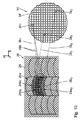
図2は、視野ファセットミラー19の設計の詳細を非常に概略的な図に示している。視野ファセットミラー19の全体の反射面25は、行と列に再分割され、個々のミラー26の格子が形成される。個々のミラー26の個々の反射面は平坦であり、湾曲していない。個々のミラー行27は、互いに直接隣り合って位置する複数の個々のミラー26を有する。1つの個々のミラー行27上には数十個から数百個の個々のミラー26を設けることができる。図2に記載の例では、個々のミラー26は正方形である。可能な限り少ない間隙を有する反射面20の占有を可能にする他の形状の個々のミラーを使用することができる。そのような代替の個々のミラー形状は、モザイク細工の数学理論から公知である。この点に関しては、WO 2009/100 856 A1に指定されている引用文献を参照されたい。
FIG. 2 shows the details of the design of the
視野ファセットミラー19の実施形態に基づいて、個々のミラー列28も同じく複数の個々のミラー26を有する。一例として、個々のミラー列28毎に数十個から数百個の個々のミラー26が設けられる。
Based on the embodiment of the
位置関係の説明を簡単にするために、図2には、ファセットミラー19の局所座標系として直交xyz座標系を描示している。ファセットミラー又はその区画を上面図に示すその後の図においても対応する局所xyz座標系を示している。図2では、x軸は、右に向けて水平に個々のミラー行27と平行に延びている。図2では、y軸は、上方に個々のミラー列28と平行に延びている。z軸は、図2の作図面と垂直に作図面から飛び出すように延びている。
In order to simplify the explanation of the positional relationship, FIG. 2 shows an orthogonal xyz coordinate system as the local coordinate system of the
図1に記載の広域座標系のy方向、すなわち、レチクル7及びウェーハ13の変位方向、すなわち、個々のミラーアレイの列方向は、互いに厳密に平行に延びる必要はなく、その代わりに例えば互いに対して小さい角度を取ることができる。
The y-direction of the global coordinate system described in FIG. 1, ie the displacement direction of the
視野ファセットミラー19の反射面25は、x方向にx0という広がりを有する。y方向には、視野ファセットミラー19の反射面25はy0という広がりを有する。
The reflecting
視野ファセットミラー19の実施形態に基づいて、個々のミラー26は、例えば500μm×500μmから例えば2mm×2mmまでの領域内のx/y広がりを有する。個々のミラー26は、照明光16に対してフォーカス効果を有するように成形することができる。個々のミラー26のそのようなフォーカス効果は、照明光16による視野ファセットミラー19の発散照明が使用される場合は特に有利である。全体の視野ファセットミラー19は、実施形態に依存して例えば300mm×300mm又は600mm×600mmのx0/y0広がりを有する。個々のミラー群24a(図7を参照されたい)は、一般的に25mm×4mm又は104mm×8mmのx/y広がりを有する。それぞれのミラー群24aのサイズとこれらの個々のミラー群24aを構成する個々のミラー26のサイズとの比に基づいて、個々のミラー群24aの各々は、適切な個数の個々のミラー26を有する。
Based on the embodiment of the
個々のミラー26の各々は、図2に反射面25の左下手コーナに配置された2つの個々のミラー26に基づいて破線で示し、かつ図3に個々のミラー行27の区画に基づいてより詳細に示すように、入射照明光16の個々の偏向の目的でそれぞれアクチュエータ29に接続される。アクチュエータ29は、個々のミラー26の反射側から離れる方向に向く個々のミラー26の各々の側に配置される。一例として、アクチュエータ29は、圧電アクチュエータとして構成することができる。そのようなアクチュエータの実施形態は、マイクロミラーアレイの設計から公知である。
Each of the individual mirrors 26 is shown in broken lines in FIG. 2 based on two
個々のミラー行27のアクチュエータ29は、それぞれ信号線30を通じて行信号バス31に接続される。1つの個々のミラー行27は、行信号バス31のそれぞれ1つに関連付けられる。個々のミラー行27の行信号バス31は、更に主信号バス32に接続される。主信号バス32は、視野ファセットミラー19の制御デバイス33への信号接続を有する。制御デバイス33は、特に線毎、すなわち、行毎又は列毎の個々のミラー26の作動に向けて構成される。個々のミラー行27及び個々のミラー列28の範囲での個々のミラー26の個々の作動も可能である。
The
個々のミラー26の各々は、互いに対して垂直な2つの傾斜軸の回りに個々に独立して傾斜させることができ、これらの傾斜軸のうちの第1のものは、x軸と平行に延び、これらの2つの傾斜軸のうちの第2のものは、y軸と平行に延びる。2つの傾斜軸は、それぞれの個々のミラー26の個々の反射面内に位置する。 Each of the individual mirrors 26 can be independently tilted about two tilt axes perpendicular to each other, the first of these tilt axes extending parallel to the x-axis. The second of these two tilt axes extends parallel to the y-axis. The two tilt axes are located in the individual reflecting surfaces of the respective individual mirrors 26.
更に、アクチュエータ29は、個々のミラー26をz方向に個々に変位させることも可能にする。従って、個々のミラー26は、反射面25に対する法線に沿って互いに分離して作動可能な方式で変位させることができる。その結果、反射面25全体のトポグラフィを変更することができる。これを図4から図6に基づいて非常に概略的な形式で例示している。その結果、ミラー区画の形態で平面に全体的にフレネルレンズの方式で配置された大きいサグ高、すなわち、反射面のトポグラフィにおいて大きい変化を有する輪郭の反射面を製造することも可能である。フレネルゾーンの様式での区画へのそのような再分割により、大きいサグ高を有するそのようなミラー面トポグラフィの基本的な湾曲が除かれる。
Furthermore, the
図4は、個々のミラー行27の全ての個々のミラー26が制御デバイス33及びアクチュエータ29によって同じ絶対z位置に設定された個々のミラー行27の区画の個々のミラー26の個々の反射面を示している。それによって個々のミラー行27の平坦な行反射面がもたらされる。視野ファセットミラー19の全ての個々のミラー26が図4に従って位置合わせされる場合に、視野ファセットミラー19の全体の反射面25が平坦である。
FIG. 4 shows the individual reflecting surfaces of the individual mirrors 26 in the section of the
図5は、中心の個々のミラー26mが、隣接する個々のミラー26r1、26r2、26r3に対して負のz方向にオフセット設定された個々のミラー行27の個々のミラー26の作動を示している。これの結果は、段状装置であり、それは、図5に記載の個々のミラー行27上に入射するEUV放射線16の対応する位相オフセットに導く。この場合に、2つの中心の個々のミラー26mによって反射されたEUV放射線16は、最大の位相リターデーションを受ける。縁部側の個々のミラー26r3は、最小の位相リターデーションを発生させる。中間の個々のミラー26r1、26r2は、中心の個々のミラー26mによる位相リターデーションから始まって相応に段毎に次第に小さい位相リターデーションを発生させる。
FIG. 5 shows the operation of an
図6は、第1に個々のミラー26の互いに対するz方向のオフセット及び第2に個々のミラー26の互いに対する向きの結果として、全体として凸面の個々のミラー行27がもたらされるような図示の個々のミラー行27の区画の個々のミラー26の作動を示している。これは、視野ファセットミラー19の個々のミラー群の結像効果を発生させるのに使用することができる。当然ながら同じ方法で、例えば、個々のミラー26の群の凹状配置も可能である。
FIG. 6 shows the illustration as a result of the first z-offset of the individual mirrors 26 with respect to each other and secondly the orientation of the individual mirrors 26 with respect to each other resulting in generally convex
図5及び図6を参照して上述したものに対応する設計は、x次元に限定されず、制御デバイス33を用いた作動に基づいて視野ファセットミラー19のy次元にわたって続けることもできる。
The designs corresponding to those described above with reference to FIGS. 5 and 6 are not limited to the x dimension, but can continue over the y dimension of the
制御デバイス33を用いたアクチュエータ29の個々の作動の結果として、それぞれ少なくとも2つの個々のミラー26から構成された上述の個々のミラー群24aを形成するために個々のミラー26の予め決定された傾斜グループ分けを設定することができる。個々のミラー群24aを照明光16に対する少なくとも1つの専用群ミラー照明チャネルを通じて物体視野5に結像するために、個々のミラー群24aは、瞳ファセットミラー20の少なくとも1つの専用瞳ファセットにそれぞれ関連付けられる。この割り当ては、個々のミラー群24aに属する個々のミラーのそれぞれの傾斜位置又はスイッチ位置を予め決定することによってもたらされる。ここで、群ミラー照明チャネルは、全体の照明視野又は物体視野5を照明するための瞳ファセットを通じての結像の結果として互いに相補し合うそれぞれの個々のミラー群24aの全ての個々のミラー照明チャネルの総計である。従って、個々のミラー群24aの各々は、照明視野5の原像であると考えることができる。照明視野又は物体視野5の全体照明は、次に、これらの原像の重ね合わせを構成する。
As a result of the individual actuation of the
従って、視野ファセットミラーのファセットの機能は、例えば、US 6,438,199 B1又はUS 6,658,084 B2に開示するように、各場合に個々のミラー群24aのうちの1つによって受け持たれる。
Thus, the facet function of the field facet mirror is in each case handled by one of the
図7は、そのようなグループ分けを例示している。図2に記載の図と比較して複数の個々のミラー26を有する視野ファセットミラー19の代替の視野ファセット板の反射面25の区画が示されている。図2から図6を参照して上述したものに対応する構成要素を同じ参照記号で表記し、これらに対しては再度詳細に説明することはしない。
FIG. 7 illustrates such grouping. A section of the
図7の例では、制御デバイス33による作動の適切な組合せにより、反射面25内に合計で12個の個々のミラー群24aが形成される。個々のミラー群24aは、それぞれ同じx/yアスペクト比を有する。個々のミラー群24aの各々は、個々のミラー26の24×3アレイから構成され、すなわち、それぞれ24個の個々のミラー26を有する3つの個々のミラー行を有する。従って、個々のミラー群24aの各々は、8対1のアスペクト比を有する。このアスペクト比は、照明される物体視野5のアスペクト比に対応する。
In the example of FIG. 7, a total of 12
個々のミラー群24aの各々内では、個々のミラー26は、個々のミラー群24aの各々の形状が従来の視野ファセットミラーの個々の視野ファセットの形状に対応するように互いに対して位置合わせされる。
Within each
図8及び図9は、個々のミラー群24aを形成するための視野ファセットミラー19の個々のミラー26のグループ分けの例を示している。この図では、個々のミラー行27に上部から下部に連続して番号を振った添字を付与している。従って、最上部の個々のミラー線を271で表記し、最下部の個々のミラー線を278で表記している。
8 and 9 show an example of grouping the individual mirrors 26 of the
図8に記載のグループ分けでは、互いに上下に位置するそれぞれ2つの個々のミラー行、すなわち、個々のミラー行272/3、274/5、及び276/7が組み合わされ、3つの個々のミラー群24a1、24a2、及び24a3を形成する。群ミラー照明チャネル351、352、及び353を通じてのこれらの個々のミラー群24a1から24a3と3つの瞳ファセット341、342、及び343との割り当ても図8に略示している。図8に記載の割り当てでは、照明光は、これらの個々のミラー群24a1から24a3に属する個々のミラー26の個々のミラー照明チャネルを通り、瞳ファセット341から343を通って照明視野5に案内され、それぞれの個々のミラー群24a1から24a3が物体視野又は照明視野5に結像される。個々のミラー群24a1から24a3の個々のミラー26は、照明光16がそれぞれの瞳ファセット341から343に案内されるように制御デバイス33を用いて傾斜される。
In the grouping described in FIG. 8, two individual mirror rows that are located one above the other, ie
図9は、個々のミラー群を形成するための視野ファセットミラー19の個々のミラー26の異なる割り当てを示している。この場合に、個々のミラー行271/2は、個々のミラー群24a4に関連付けられ、個々のミラー行273/4は、個々のミラー群24a5に関連付けられ、個々のミラー行275/6は、個々のミラー群24a6に関連付けられ、個々のミラー行277/8は、個々のミラー群24a7に関連付けられる。個々のミラー群24a4から24a7は、更に、図8に記載の割り当てによる瞳ファセット341から343とは異なる瞳ファセット344から347に群ミラー照明チャネル354から357を通じて関連付けられる。個々のミラー群24a4から24a7は、ここでもまた、群ミラー照明チャネル354から357を通じ、瞳ファセット344から347を通じて物体視野又は照明視野5に結像される。
FIG. 9 shows different assignments of the individual mirrors 26 of the
図9に記載の割り当てでは、瞳ファセット341から343は、照明されないままに留まる。相応に図8に記載の割り当てでは、瞳ファセット344から347が照明されないままに留まる。
In the assignment described in FIG. 9, the
瞳ファセット34への個々のミラー群24aの2つの異なる割り当ては、物体視野又は照明視野5の照明において相応に異なる照明角度分布をもたらす。これらの異なる照明角度分布を照明設定とも呼ぶ。
Two different assignments of the
図8及び図9の割り当て例では、個々のミラー行272から277の個々のミラー26は、2つの異なる個々のミラー群24aに属する。一例として、個々のミラー行272は、第1に個々のミラー群24a1に属し、第2に個々のミラー群24a4に属する。これらの異なる個々のミラー群、すなわち、例えば個々のミラー群24a1,24a4は、それぞれ専用の第2のファセット、すなわち、図示の例では瞳ファセット341及び344に専用群ミラー照明チャネル、すなわち、例えば群ミラー照明チャネル351及び354を通じて関連付けられる。
The allocation example of FIG. 8 and FIG. 9, the individual mirrors 26 of the
図8及び図9に記載の実施形態において、視野ファセットミラー19の個々のミラー26の過半数、すなわち、個々のミラー行272から277の個々のミラーは、専用群ミラー照明チャネル35を通じて専用の第2のファセット34にそれぞれ関連付けられた少なくとも2つの個々のミラー群24aに属する。個々のミラー行272から277のこれらの個々のミラーは、上述したように、それぞれちょうど2つの個々のミラー群24aに属する。ある一定の個々のミラー26が多数の個々のミラー群24aに属する照明幾何学形状も可能であることは自明である。一例として、個々のミラー群24aが3つの個々のミラー行27から構成される場合に、図8及び図9に関して上述したものと同様に、これらの3つの個々のミラー行のうちの1つが、第1のグループ分けにおいて第1の個々のミラー群の上側の個々のミラー行を構成し、第2のグループ分けにおいて第2の個々のミラー群の中心行を構成し、第3のグループ分けにおいて第3の個々のミラー群の下側行を構成するグループ分け割り当てを予め決定することが可能である。
In the embodiment according to FIGS. 8 and 9, the individual mirrors 26 of the field facet mirror 19 a majority, i.e., the individual mirrors of the individual mirrors
図8及び図9に記載の実施形態において、個々のミラー26のうちのいずれも、2つよりも多い個々のミラー群24aに属さない。図8及び図9に記載の代替のグループ分け割り当てでは、個々のミラー群24a、すなわち、例えば、図8に記載のグループ分け割り当ての個々のミラー群24a1と図9に記載のグループ分け割り当ての個々のミラー群24a4とは、これらの個々のミラー群24a1,24a4の個々のミラー26、すなわち、個々のミラー行272の個々のミラー26の全てのうちの50%が両方の個々のミラー群24a1,24a4に同時に属するように重なる。図8及び図9に記載の実施形態において、それぞれ3つの個々のミラー群が存在し、すなわち、例えば、個々のミラー群24a4及び24a5の各々が、個々のミラー群24a1と重なるが、互いには重なり合わないように互いに重なる図9に記載のグループ分け割り当ての個々のミラー群24a4、24a5と図8に記載のグループ分け割り当ての個々のミラー群24a1とが存在する。
In the embodiment described in FIGS. 8 and 9, none of the individual mirrors 26 belong to more than two
視野ファセットミラー36の変形を使用する場合のグループ分け割り当ての代替実施形態を図10に例示している。図1から図9を参照して上述したものに対応する構成要素を同じ参照記号で表記し、これらに対して、再度詳細に説明することはしない。
An alternative embodiment of grouping assignment when using a variant of the
視野ファセットミラー19と同様に、視野ファセットミラー36は、個々のミラー26の格子に再分割される。しかし、視野ファセットミラー36では、この格子の行及び列は、それぞれ物体変位方向yに対して45°の角度で延びている。図10に記載の視野ファセットミラー36と視野ファセットミラー19の間の更に別の相違点は、個々のミラー群24aが矩形ではなく弓形の様式で囲まれる点である。これらの弓形の個々のミラー群24aは、それぞれ関連付けられた瞳ファセット34と、任意的に、原則的に従来技術で公知の下流伝達光学ユニットとを通じて弓形の物体視野又は照明視野内に相応に結像される。
Similar to the
図10では、個々のミラー群24aの弓形縁部をそれぞれ実線で例示している。50%を超えるものがそれぞれこの縁部内に位置する個々のミラー26は、それぞれの個々のミラー群24aに属する。
In FIG. 10, the arcuate edges of the
図10には、瞳ファセット34への個々のミラー群24aの2つの異なるグループ分け割り当てを示している。第1のグループ分け割り当てでは、上下に位置して互いに接する2つの個々のミラー群24a1,24a2の個々のミラー26が、群ミラー照明チャネル351、352を通じて2つの瞳ファセット341、342に関連付けられる。代替のグループ分け割り当てでは、半分がこれらの2つの第1の個々のミラー群24a1、24a2と重なる第3の個々のミラー群24a3が、第3の群ミラー照明チャネル353を通じて第3の瞳ファセット343に関連付けられる。
FIG. 10 shows two different grouping assignments of
図10では、2つの異なる個々のミラー群24a2及び24a3に属する個々のミラー260のうちの1つを例示的に強調表示している。この個々のミラー260は、ちょうど2つの個々のミラー群、すなわち、個々のミラー群24a2及び24a3に属する。
In Figure 10, it is displayed illustratively highlight one of the two different individual mirrors 26 belonging to
図10には、個々のミラー照明チャネル35aのうちの一部も例示的に示している。照明光16の照明光部分ビームは、それぞれの個々のミラー26から個々のミラー照明チャネル35aを通じ、それぞれの瞳ファセット34を通じて照明視野又は物体視野5に案内される。
FIG. 10 also exemplarily shows a part of the individual
図10に記載の実施形態において、2つの個々のミラー群24a1と24a3は、例えば、これら2つの個々のミラー群24a1、24a3の個々のミラー26の全てのうちの約50%が両方の個々のミラー群24a1、24a3に同時に属するように互いに同じく重なる。一方で2つの個々のミラー群24a1と24a3、及び他方で個々のミラー群24a2と24a3は、それぞれ約50%だけ重複し、それに対して2つの個々のミラー群24a1と24a3は、互いに重なり合わない。
In the embodiment described in FIG. 10, the two
視野ファセットミラー19及び36では、瞳ファセットミラー20が、関連付けられた群ミラー照明チャネル35を通じて照明光16が入射することができる遥かにより多数の瞳ファセット34を有することができるように、個々のミラー群24aを形成するための個々のミラー26の代替の割り当てにより、個々のミラー群24aを形成するのに多くの異なる方法で個々のミラー26をグループ分けすることができる。これによって異なる照明設定の選択が著しく増加する。
In the field facet mirrors 19 and 36, the individual facet mirrors 20 can have a much larger number of
微細構造化又はナノ構造化構成要素、特に半導体構成要素、例えばマイクロチップのリソグラフィを用いる生成に対して、投影露光装置1を用いて、物体視野5内のレチクルの少なくとも一部は、像視野11内のウェーハ13上の感光層の領域上に結像される。投影露光装置1がスキャナ又はステッパとしてそのいずれに具現化されるかに応じて、レチクル7とウェーハ13は、スキャナ動作で連続的に又はステッパ動作で逐次にいずれかで時間同期でy方向に変位される。
For production using lithography of microstructured or nanostructured components, in particular semiconductor components, for example microchips, using the projection exposure apparatus 1, at least a part of the reticle in the
20 瞳ファセットミラー
26 個々のミラー
260 2つの異なる個々のミラー群24a2及び24a3に属する個々のミラーのうちの1つ
35a 個々のミラー照明チャネル
20
Claims (10)
少なくとも2つの傾斜位置の間で切り換えることができ、照明光部分ビームを前記物体視野(5)に案内するための個々のミラー照明チャネル(35a)を与える多数の個々のミラー(26)を含む第1のファセットミラー(19;36)を有し、
前記照明光(16)のビーム経路内で前記第1のファセットミラー(19;36)の下流に配置され、かつ群ミラー照明チャネル(35)を通じた前記物体視野(5)内への該第1のファセットミラー(19;36)の、前記個々のミラー(26)を複数含むミラー群(24a)の結像にそれぞれ寄与する複数のファセット(34)を有する第2のファセットミラー(20)であって、個々の該ミラー群(24a)の該像が、該物体視野(5)内で互いの上に重ね合わされる前記第2のファセットミラー(20)を有し、
前記個々のミラー(26)の少なくとも一部(260)が、該個々のミラーのそれぞれの前記傾斜位置に応じて少なくとも1つの専用群ミラー照明チャネル(351,354;351,353)を通じて少なくとも1つの専用の第2のファセット(341,343)にそれぞれ関連付けることができる前記個々のミラー群(24a1,24a4;24a1,24a3)のうちの少なくとも2つの異なる群に属し、
前記第1のファセットミラー(19;36)の前記個々のミラー(26)のうちの過半数が、専用群ミラー照明チャネル(351,354;351,353)を通じて専用の第2のファセット(341,343)にそれぞれ関連付けられた前記個々のミラー群のうちの少なくとも2つ(24a1,24a4;24a1,24a3)に属し、
前記個々のミラー群(24a)の前記像は、前記物体視野(5)の寸法(x,y)について同じアスペクト比を有する、
ことを特徴とする照明光学ユニット(4)。 An illumination optical unit (4) for EUV projection lithography for guiding illumination light (16) to an object field (5) in which a lithographic mask (7) can be placed,
A first one comprising a number of individual mirrors (26) which can be switched between at least two tilt positions and provide individual mirror illumination channels (35a) for guiding the illumination light partial beam to the object field (5). One facet mirror (19; 36),
The first into the object field (5) disposed downstream of the first facet mirror (19; 36) in the beam path of the illumination light (16) and through a group mirror illumination channel (35). A second facet mirror (20) having a plurality of facets (34) each contributing to image formation of a mirror group (24a) including a plurality of the individual mirrors (26). The images of the individual mirror groups (24a) have the second facet mirror (20) superimposed on each other in the object field (5);
At least a portion (26 0 ) of the individual mirror (26) has at least one dedicated group mirror illumination channel (35 1 , 35 4 ; 35 1 , 35 3 depending on the respective tilted position of the individual mirror. ) Through at least two different groups of said individual mirror groups (24a 1 , 24a 4 ; 24a 1 , 24a 3 ) that can be associated respectively with at least one dedicated second facet (34 1 , 34 3 ) belong to,
A majority of the individual mirrors (26) of the first facet mirror (19; 36) are dedicated second facets through dedicated group mirror illumination channels (35 1 , 35 4 ; 35 1 , 35 3 ). belongs to; (24a 1, 24a 3 24a 1, 24a 4), (34 1, 34 3) at least two of the individual mirrors respectively associated with
The image of the individual mirrors (24a) is closed the same aspect ratio for the dimension (x, y) of the object field (5),
An illumination optical unit (4) characterized by the above.
前記3つの個々のミラー群のうちの前記第1の群(24a4;24a1)及び前記第3の群(24a5;24a2)は、互いに重なり合わない、
ことを特徴とする請求項1から請求項5のいずれか1項に記載の照明光学ユニット。 Private group mirror illumination channels (35 1, 35 4, 35 5; 35 1, 35 2, 35 3) through a dedicated second facet (34 1, 34 4, 34 5; 34 1, 34 2, 34 3) Three individual mirror groups (24a 1 , 24a 4 , 24a 5 ; 24a 1 , 24a 2 , 24a 3 ) respectively associated with the three individual mirror groups (24a 1 , 24a 4 , 24a 5 ; 24a 1, 24a 2, 24a 3) the first group (24a 4 of; 24a 1) is a second group of said three individual mirrors (24a 1; overlap 24a 3), and the 3 The second group (24a 1 ; 24a 3 ) of the three individual mirror groups overlaps each other such that it overlaps the third group (24a 5 ; 24a 2 ) of the three individual mirror groups;
Of the three individual mirror groups, the first group (24a 4 ; 24a 1 ) and the third group (24a 5 ; 24a 2 ) do not overlap each other;
The illumination optical unit according to any one of claims 1 to 5 , wherein
物体視野(5)を像視野(11)に結像するための投影光学ユニット(10)を有する、
ことを特徴とする照明系。 The illumination optical unit according to any one of claims 1 to 6 ,
A projection optical unit (10) for imaging the object field (5) into the image field (11);
An illumination system characterized by that.
EUV光源(2)を有し、
物体変位ドライブ(9)を用いて変位方向(y)に沿って変位可能である物体視野(5)に物体(7)を保持するための物体ホルダ(8)を有し、
ウェーハ変位ドライブ(15)を用いて前記変位方向(y)に沿って変位可能である像視野(11)にウェーハ(13)を保持するためのウェーハホルダ(14)を有する、
ことを特徴とする投影露光装置。 An illumination system (3) according to claim 7 ,
An EUV light source (2),
Having an object holder (8) for holding the object (7) in an object field (5) which is displaceable along the displacement direction (y) using an object displacement drive (9);
A wafer holder (14) for holding the wafer (13) in an image field (11) that is displaceable along said displacement direction (y) using a wafer displacement drive (15);
A projection exposure apparatus.
感光材料の層が少なくとも部分的に塗布されたウェーハ(13)を与える段階と、
結像される構造を有するレチクル(7)を与える段階と、
請求項8又は請求項9に記載の投影露光装置(1)を与える段階と、 前記投影露光装置(1)の投影光学ユニット(10)を用いて前記レチクル(7)の少なくとも一部を前記層の領域上に投影する段階と、
を含むことを特徴とする方法。 A method for producing a microstructured or nanostructured component comprising:
Providing a wafer (13) having a layer of photosensitive material applied at least partially;
Providing a reticle (7) having a structure to be imaged;
A step of providing a projection exposure apparatus (1) according to claim 8 or 9 , and at least part of the reticle (7) using the projection optical unit (10) of the projection exposure apparatus (1) as the layer Projecting onto the area of
A method comprising the steps of:
Applications Claiming Priority (5)
| Application Number | Priority Date | Filing Date | Title |
|---|---|---|---|
| US201261646965P | 2012-05-15 | 2012-05-15 | |
| US61/646965 | 2012-05-15 | ||
| DE102012208064.3 | 2012-05-15 | ||
| DE102012208064A DE102012208064A1 (en) | 2012-05-15 | 2012-05-15 | Illumination optics for EUV projection lithography |
| PCT/EP2013/059016 WO2013171071A1 (en) | 2012-05-15 | 2013-04-30 | Illumination optical unit for euv projection lithography |
Publications (3)
| Publication Number | Publication Date |
|---|---|
| JP2015517733A JP2015517733A (en) | 2015-06-22 |
| JP2015517733A5 JP2015517733A5 (en) | 2017-06-15 |
| JP6332758B2 true JP6332758B2 (en) | 2018-05-30 |
Family
ID=49510925
Family Applications (1)
| Application Number | Title | Priority Date | Filing Date |
|---|---|---|---|
| JP2015511982A Active JP6332758B2 (en) | 2012-05-15 | 2013-04-30 | Illumination optical unit for EUV projection lithography |
Country Status (4)
| Country | Link |
|---|---|
| US (1) | US10126658B2 (en) |
| JP (1) | JP6332758B2 (en) |
| DE (1) | DE102012208064A1 (en) |
| WO (1) | WO2013171071A1 (en) |
Families Citing this family (4)
| Publication number | Priority date | Publication date | Assignee | Title |
|---|---|---|---|---|
| DE102014217611A1 (en) * | 2014-09-03 | 2016-03-03 | Carl Zeiss Smt Gmbh | Illumination optics for projection lithography |
| WO2016078818A1 (en) * | 2014-11-18 | 2016-05-26 | Carl Zeiss Smt Gmbh | Optical subsystem for projection lithography and illumination optical unit for projection lithography |
| DE102017217266A1 (en) * | 2017-09-28 | 2019-03-28 | Carl Zeiss Smt Gmbh | Method for determining properties of an EUV source |
| DE102021202768A1 (en) * | 2021-03-22 | 2022-09-22 | Carl Zeiss Smt Gmbh | FACETING SYSTEM AND LITHOGRAPHY PLANT |
Family Cites Families (13)
| Publication number | Priority date | Publication date | Assignee | Title |
|---|---|---|---|---|
| DE10053587A1 (en) | 2000-10-27 | 2002-05-02 | Zeiss Carl | Lighting system with variable adjustment of the illumination |
| DE10138313A1 (en) | 2001-01-23 | 2002-07-25 | Zeiss Carl | Collector for lighting systems with a wavelength <193 nm |
| US6859515B2 (en) | 1998-05-05 | 2005-02-22 | Carl-Zeiss-Stiftung Trading | Illumination system, particularly for EUV lithography |
| US6438199B1 (en) | 1998-05-05 | 2002-08-20 | Carl-Zeiss-Stiftung | Illumination system particularly for microlithography |
| JP4099423B2 (en) * | 2002-03-18 | 2008-06-11 | エーエスエムエル ネザーランズ ビー.ブイ. | Lithographic apparatus and device manufacturing method |
| DE102006020734A1 (en) * | 2006-05-04 | 2007-11-15 | Carl Zeiss Smt Ag | Illumination system for the EUV lithography and first and second optical element for use in such a lighting system |
| JPWO2007138805A1 (en) * | 2006-05-25 | 2009-10-01 | 株式会社ニコン | Illumination optical apparatus, exposure apparatus, and device manufacturing method |
| DE102008009600A1 (en) * | 2008-02-15 | 2009-08-20 | Carl Zeiss Smt Ag | Facet mirror e.g. field facet mirror, for use as bundle-guiding optical component in illumination optics of projection exposure apparatus, has single mirror tiltable by actuators, where object field sections are smaller than object field |
| CN101946190B (en) * | 2008-02-15 | 2013-06-19 | 卡尔蔡司Smt有限责任公司 | Facet mirror for use in a projection exposure apparatus for microlithography |
| DE102008049586A1 (en) * | 2008-09-30 | 2010-04-08 | Carl Zeiss Smt Ag | Field facet mirror for use in illumination optics of a projection exposure apparatus for EUV microlithography |
| DE102009030501A1 (en) * | 2009-06-24 | 2011-01-05 | Carl Zeiss Smt Ag | Imaging optics for imaging an object field in an image field and illumination optics for illuminating an object field |
| DE102011004615A1 (en) * | 2010-03-17 | 2011-09-22 | Carl Zeiss Smt Gmbh | Illumination optics for projection lithography |
| DE102011076145B4 (en) * | 2011-05-19 | 2013-04-11 | Carl Zeiss Smt Gmbh | A method for assigning a pupil facet of a pupil facet mirror of an illumination optical unit of a projection exposure apparatus to a field facet of a field facet mirror of the illumination optics |
-
2012
- 2012-05-15 DE DE102012208064A patent/DE102012208064A1/en not_active Ceased
-
2013
- 2013-04-30 JP JP2015511982A patent/JP6332758B2/en active Active
- 2013-04-30 WO PCT/EP2013/059016 patent/WO2013171071A1/en active Application Filing
-
2014
- 2014-10-17 US US14/517,139 patent/US10126658B2/en active Active
Also Published As
| Publication number | Publication date |
|---|---|
| US10126658B2 (en) | 2018-11-13 |
| US20150036115A1 (en) | 2015-02-05 |
| DE102012208064A1 (en) | 2013-11-21 |
| WO2013171071A1 (en) | 2013-11-21 |
| JP2015517733A (en) | 2015-06-22 |
Similar Documents
| Publication | Publication Date | Title |
|---|---|---|
| JP6121581B2 (en) | Faceted mirror used in projection exposure equipment for microlithography | |
| JP6493584B2 (en) | Illumination optical unit for EUV projection lithography | |
| TWI397786B (en) | Illumination optical unit for projection lithography | |
| JP6253163B2 (en) | Illumination optics unit for projection lithography | |
| TWI610140B (en) | Illumination optical unit for a projection exposure apparatus | |
| US9791784B2 (en) | Assembly for a projection exposure apparatus for EUV projection lithography | |
| JP6332758B2 (en) | Illumination optical unit for EUV projection lithography | |
| JP2017526968A (en) | Faceted mirror for illumination optics unit for projection lithography | |
| JP6499658B2 (en) | Micro mirror array | |
| JP6987817B2 (en) | Lighting system and lighting optics for EUV projection lithography | |
| KR101388406B1 (en) | Method for setting an illumination geometry for an illumination optical unit for EUV projection lithography | |
| KR20150053995A (en) | Illumination system of a microliteographic projection exposure apparatus | |
| KR102631210B1 (en) | Faceted mirrors for EUV projection lithography and illumination optical units containing such faceted mirrors | |
| CN111656245B (en) | Illumination optical unit for projection lithography | |
| US20170160642A1 (en) | Illumination optical unit for euv projection lithography | |
| JP2017526969A5 (en) | ||
| JP6410741B2 (en) | Illumination optics unit for projection lithography | |
| KR102559786B1 (en) | Optical system of microlithographic projection exposure equipment | |
| JP2016517026A5 (en) |
Legal Events
| Date | Code | Title | Description |
|---|---|---|---|
| A621 | Written request for application examination |
Free format text: JAPANESE INTERMEDIATE CODE: A621 Effective date: 20160428 |
|
| A977 | Report on retrieval |
Free format text: JAPANESE INTERMEDIATE CODE: A971007 Effective date: 20170118 |
|
| A131 | Notification of reasons for refusal |
Free format text: JAPANESE INTERMEDIATE CODE: A131 Effective date: 20170125 |
|
| A524 | Written submission of copy of amendment under article 19 pct |
Free format text: JAPANESE INTERMEDIATE CODE: A524 Effective date: 20170425 |
|
| A131 | Notification of reasons for refusal |
Free format text: JAPANESE INTERMEDIATE CODE: A131 Effective date: 20170906 |
|
| A601 | Written request for extension of time |
Free format text: JAPANESE INTERMEDIATE CODE: A601 Effective date: 20171108 |
|
| A521 | Request for written amendment filed |
Free format text: JAPANESE INTERMEDIATE CODE: A523 Effective date: 20180306 |
|
| TRDD | Decision of grant or rejection written | ||
| A01 | Written decision to grant a patent or to grant a registration (utility model) |
Free format text: JAPANESE INTERMEDIATE CODE: A01 Effective date: 20180328 |
|
| A61 | First payment of annual fees (during grant procedure) |
Free format text: JAPANESE INTERMEDIATE CODE: A61 Effective date: 20180419 |
|
| R150 | Certificate of patent or registration of utility model |
Ref document number: 6332758 Country of ref document: JP Free format text: JAPANESE INTERMEDIATE CODE: R150 |
|
| R250 | Receipt of annual fees |
Free format text: JAPANESE INTERMEDIATE CODE: R250 |
|
| R250 | Receipt of annual fees |
Free format text: JAPANESE INTERMEDIATE CODE: R250 |
|
| R250 | Receipt of annual fees |
Free format text: JAPANESE INTERMEDIATE CODE: R250 |