JP6327871B2 - Work vehicle and charge control method for work vehicle - Google Patents
Work vehicle and charge control method for work vehicle Download PDFInfo
- Publication number
- JP6327871B2 JP6327871B2 JP2014015943A JP2014015943A JP6327871B2 JP 6327871 B2 JP6327871 B2 JP 6327871B2 JP 2014015943 A JP2014015943 A JP 2014015943A JP 2014015943 A JP2014015943 A JP 2014015943A JP 6327871 B2 JP6327871 B2 JP 6327871B2
- Authority
- JP
- Japan
- Prior art keywords
- motor
- rotating element
- clutch
- energy
- engine
- Prior art date
- Legal status (The legal status is an assumption and is not a legal conclusion. Google has not performed a legal analysis and makes no representation as to the accuracy of the status listed.)
- Active
Links
Images


Classifications
-
- B—PERFORMING OPERATIONS; TRANSPORTING
- B60—VEHICLES IN GENERAL
- B60K—ARRANGEMENT OR MOUNTING OF PROPULSION UNITS OR OF TRANSMISSIONS IN VEHICLES; ARRANGEMENT OR MOUNTING OF PLURAL DIVERSE PRIME-MOVERS IN VEHICLES; AUXILIARY DRIVES FOR VEHICLES; INSTRUMENTATION OR DASHBOARDS FOR VEHICLES; ARRANGEMENTS IN CONNECTION WITH COOLING, AIR INTAKE, GAS EXHAUST OR FUEL SUPPLY OF PROPULSION UNITS IN VEHICLES
- B60K6/00—Arrangement or mounting of plural diverse prime-movers for mutual or common propulsion, e.g. hybrid propulsion systems comprising electric motors and internal combustion engines ; Control systems therefor, i.e. systems controlling two or more prime movers, or controlling one of these prime movers and any of the transmission, drive or drive units Informative references: mechanical gearings with secondary electric drive F16H3/72; arrangements for handling mechanical energy structurally associated with the dynamo-electric machine H02K7/00; machines comprising structurally interrelated motor and generator parts H02K51/00; dynamo-electric machines not otherwise provided for in H02K see H02K99/00
- B60K6/20—Arrangement or mounting of plural diverse prime-movers for mutual or common propulsion, e.g. hybrid propulsion systems comprising electric motors and internal combustion engines ; Control systems therefor, i.e. systems controlling two or more prime movers, or controlling one of these prime movers and any of the transmission, drive or drive units Informative references: mechanical gearings with secondary electric drive F16H3/72; arrangements for handling mechanical energy structurally associated with the dynamo-electric machine H02K7/00; machines comprising structurally interrelated motor and generator parts H02K51/00; dynamo-electric machines not otherwise provided for in H02K see H02K99/00 the prime-movers consisting of electric motors and internal combustion engines, e.g. HEVs
- B60K6/42—Arrangement or mounting of plural diverse prime-movers for mutual or common propulsion, e.g. hybrid propulsion systems comprising electric motors and internal combustion engines ; Control systems therefor, i.e. systems controlling two or more prime movers, or controlling one of these prime movers and any of the transmission, drive or drive units Informative references: mechanical gearings with secondary electric drive F16H3/72; arrangements for handling mechanical energy structurally associated with the dynamo-electric machine H02K7/00; machines comprising structurally interrelated motor and generator parts H02K51/00; dynamo-electric machines not otherwise provided for in H02K see H02K99/00 the prime-movers consisting of electric motors and internal combustion engines, e.g. HEVs characterised by the architecture of the hybrid electric vehicle
- B60K6/44—Series-parallel type
- B60K6/445—Differential gearing distribution type
-
- B—PERFORMING OPERATIONS; TRANSPORTING
- B60—VEHICLES IN GENERAL
- B60K—ARRANGEMENT OR MOUNTING OF PROPULSION UNITS OR OF TRANSMISSIONS IN VEHICLES; ARRANGEMENT OR MOUNTING OF PLURAL DIVERSE PRIME-MOVERS IN VEHICLES; AUXILIARY DRIVES FOR VEHICLES; INSTRUMENTATION OR DASHBOARDS FOR VEHICLES; ARRANGEMENTS IN CONNECTION WITH COOLING, AIR INTAKE, GAS EXHAUST OR FUEL SUPPLY OF PROPULSION UNITS IN VEHICLES
- B60K6/00—Arrangement or mounting of plural diverse prime-movers for mutual or common propulsion, e.g. hybrid propulsion systems comprising electric motors and internal combustion engines ; Control systems therefor, i.e. systems controlling two or more prime movers, or controlling one of these prime movers and any of the transmission, drive or drive units Informative references: mechanical gearings with secondary electric drive F16H3/72; arrangements for handling mechanical energy structurally associated with the dynamo-electric machine H02K7/00; machines comprising structurally interrelated motor and generator parts H02K51/00; dynamo-electric machines not otherwise provided for in H02K see H02K99/00
- B60K6/20—Arrangement or mounting of plural diverse prime-movers for mutual or common propulsion, e.g. hybrid propulsion systems comprising electric motors and internal combustion engines ; Control systems therefor, i.e. systems controlling two or more prime movers, or controlling one of these prime movers and any of the transmission, drive or drive units Informative references: mechanical gearings with secondary electric drive F16H3/72; arrangements for handling mechanical energy structurally associated with the dynamo-electric machine H02K7/00; machines comprising structurally interrelated motor and generator parts H02K51/00; dynamo-electric machines not otherwise provided for in H02K see H02K99/00 the prime-movers consisting of electric motors and internal combustion engines, e.g. HEVs
- B60K6/22—Arrangement or mounting of plural diverse prime-movers for mutual or common propulsion, e.g. hybrid propulsion systems comprising electric motors and internal combustion engines ; Control systems therefor, i.e. systems controlling two or more prime movers, or controlling one of these prime movers and any of the transmission, drive or drive units Informative references: mechanical gearings with secondary electric drive F16H3/72; arrangements for handling mechanical energy structurally associated with the dynamo-electric machine H02K7/00; machines comprising structurally interrelated motor and generator parts H02K51/00; dynamo-electric machines not otherwise provided for in H02K see H02K99/00 the prime-movers consisting of electric motors and internal combustion engines, e.g. HEVs characterised by apparatus, components or means specially adapted for HEVs
- B60K6/36—Arrangement or mounting of plural diverse prime-movers for mutual or common propulsion, e.g. hybrid propulsion systems comprising electric motors and internal combustion engines ; Control systems therefor, i.e. systems controlling two or more prime movers, or controlling one of these prime movers and any of the transmission, drive or drive units Informative references: mechanical gearings with secondary electric drive F16H3/72; arrangements for handling mechanical energy structurally associated with the dynamo-electric machine H02K7/00; machines comprising structurally interrelated motor and generator parts H02K51/00; dynamo-electric machines not otherwise provided for in H02K see H02K99/00 the prime-movers consisting of electric motors and internal combustion engines, e.g. HEVs characterised by apparatus, components or means specially adapted for HEVs characterised by the transmission gearings
- B60K6/365—Arrangement or mounting of plural diverse prime-movers for mutual or common propulsion, e.g. hybrid propulsion systems comprising electric motors and internal combustion engines ; Control systems therefor, i.e. systems controlling two or more prime movers, or controlling one of these prime movers and any of the transmission, drive or drive units Informative references: mechanical gearings with secondary electric drive F16H3/72; arrangements for handling mechanical energy structurally associated with the dynamo-electric machine H02K7/00; machines comprising structurally interrelated motor and generator parts H02K51/00; dynamo-electric machines not otherwise provided for in H02K see H02K99/00 the prime-movers consisting of electric motors and internal combustion engines, e.g. HEVs characterised by apparatus, components or means specially adapted for HEVs characterised by the transmission gearings with the gears having orbital motion
-
- B—PERFORMING OPERATIONS; TRANSPORTING
- B60—VEHICLES IN GENERAL
- B60K—ARRANGEMENT OR MOUNTING OF PROPULSION UNITS OR OF TRANSMISSIONS IN VEHICLES; ARRANGEMENT OR MOUNTING OF PLURAL DIVERSE PRIME-MOVERS IN VEHICLES; AUXILIARY DRIVES FOR VEHICLES; INSTRUMENTATION OR DASHBOARDS FOR VEHICLES; ARRANGEMENTS IN CONNECTION WITH COOLING, AIR INTAKE, GAS EXHAUST OR FUEL SUPPLY OF PROPULSION UNITS IN VEHICLES
- B60K6/00—Arrangement or mounting of plural diverse prime-movers for mutual or common propulsion, e.g. hybrid propulsion systems comprising electric motors and internal combustion engines ; Control systems therefor, i.e. systems controlling two or more prime movers, or controlling one of these prime movers and any of the transmission, drive or drive units Informative references: mechanical gearings with secondary electric drive F16H3/72; arrangements for handling mechanical energy structurally associated with the dynamo-electric machine H02K7/00; machines comprising structurally interrelated motor and generator parts H02K51/00; dynamo-electric machines not otherwise provided for in H02K see H02K99/00
- B60K6/20—Arrangement or mounting of plural diverse prime-movers for mutual or common propulsion, e.g. hybrid propulsion systems comprising electric motors and internal combustion engines ; Control systems therefor, i.e. systems controlling two or more prime movers, or controlling one of these prime movers and any of the transmission, drive or drive units Informative references: mechanical gearings with secondary electric drive F16H3/72; arrangements for handling mechanical energy structurally associated with the dynamo-electric machine H02K7/00; machines comprising structurally interrelated motor and generator parts H02K51/00; dynamo-electric machines not otherwise provided for in H02K see H02K99/00 the prime-movers consisting of electric motors and internal combustion engines, e.g. HEVs
- B60K6/22—Arrangement or mounting of plural diverse prime-movers for mutual or common propulsion, e.g. hybrid propulsion systems comprising electric motors and internal combustion engines ; Control systems therefor, i.e. systems controlling two or more prime movers, or controlling one of these prime movers and any of the transmission, drive or drive units Informative references: mechanical gearings with secondary electric drive F16H3/72; arrangements for handling mechanical energy structurally associated with the dynamo-electric machine H02K7/00; machines comprising structurally interrelated motor and generator parts H02K51/00; dynamo-electric machines not otherwise provided for in H02K see H02K99/00 the prime-movers consisting of electric motors and internal combustion engines, e.g. HEVs characterised by apparatus, components or means specially adapted for HEVs
- B60K6/38—Arrangement or mounting of plural diverse prime-movers for mutual or common propulsion, e.g. hybrid propulsion systems comprising electric motors and internal combustion engines ; Control systems therefor, i.e. systems controlling two or more prime movers, or controlling one of these prime movers and any of the transmission, drive or drive units Informative references: mechanical gearings with secondary electric drive F16H3/72; arrangements for handling mechanical energy structurally associated with the dynamo-electric machine H02K7/00; machines comprising structurally interrelated motor and generator parts H02K51/00; dynamo-electric machines not otherwise provided for in H02K see H02K99/00 the prime-movers consisting of electric motors and internal combustion engines, e.g. HEVs characterised by apparatus, components or means specially adapted for HEVs characterised by the driveline clutches
- B60K6/387—Actuated clutches, i.e. clutches engaged or disengaged by electric, hydraulic or mechanical actuating means
-
- B—PERFORMING OPERATIONS; TRANSPORTING
- B60—VEHICLES IN GENERAL
- B60K—ARRANGEMENT OR MOUNTING OF PROPULSION UNITS OR OF TRANSMISSIONS IN VEHICLES; ARRANGEMENT OR MOUNTING OF PLURAL DIVERSE PRIME-MOVERS IN VEHICLES; AUXILIARY DRIVES FOR VEHICLES; INSTRUMENTATION OR DASHBOARDS FOR VEHICLES; ARRANGEMENTS IN CONNECTION WITH COOLING, AIR INTAKE, GAS EXHAUST OR FUEL SUPPLY OF PROPULSION UNITS IN VEHICLES
- B60K6/00—Arrangement or mounting of plural diverse prime-movers for mutual or common propulsion, e.g. hybrid propulsion systems comprising electric motors and internal combustion engines ; Control systems therefor, i.e. systems controlling two or more prime movers, or controlling one of these prime movers and any of the transmission, drive or drive units Informative references: mechanical gearings with secondary electric drive F16H3/72; arrangements for handling mechanical energy structurally associated with the dynamo-electric machine H02K7/00; machines comprising structurally interrelated motor and generator parts H02K51/00; dynamo-electric machines not otherwise provided for in H02K see H02K99/00
- B60K6/20—Arrangement or mounting of plural diverse prime-movers for mutual or common propulsion, e.g. hybrid propulsion systems comprising electric motors and internal combustion engines ; Control systems therefor, i.e. systems controlling two or more prime movers, or controlling one of these prime movers and any of the transmission, drive or drive units Informative references: mechanical gearings with secondary electric drive F16H3/72; arrangements for handling mechanical energy structurally associated with the dynamo-electric machine H02K7/00; machines comprising structurally interrelated motor and generator parts H02K51/00; dynamo-electric machines not otherwise provided for in H02K see H02K99/00 the prime-movers consisting of electric motors and internal combustion engines, e.g. HEVs
- B60K6/50—Architecture of the driveline characterised by arrangement or kind of transmission units
- B60K6/54—Transmission for changing ratio
- B60K6/547—Transmission for changing ratio the transmission being a stepped gearing
-
- B—PERFORMING OPERATIONS; TRANSPORTING
- B60—VEHICLES IN GENERAL
- B60W—CONJOINT CONTROL OF VEHICLE SUB-UNITS OF DIFFERENT TYPE OR DIFFERENT FUNCTION; CONTROL SYSTEMS SPECIALLY ADAPTED FOR HYBRID VEHICLES; ROAD VEHICLE DRIVE CONTROL SYSTEMS FOR PURPOSES NOT RELATED TO THE CONTROL OF A PARTICULAR SUB-UNIT
- B60W10/00—Conjoint control of vehicle sub-units of different type or different function
- B60W10/18—Conjoint control of vehicle sub-units of different type or different function including control of braking systems
- B60W10/182—Conjoint control of vehicle sub-units of different type or different function including control of braking systems including control of parking brakes
-
- B—PERFORMING OPERATIONS; TRANSPORTING
- B60—VEHICLES IN GENERAL
- B60W—CONJOINT CONTROL OF VEHICLE SUB-UNITS OF DIFFERENT TYPE OR DIFFERENT FUNCTION; CONTROL SYSTEMS SPECIALLY ADAPTED FOR HYBRID VEHICLES; ROAD VEHICLE DRIVE CONTROL SYSTEMS FOR PURPOSES NOT RELATED TO THE CONTROL OF A PARTICULAR SUB-UNIT
- B60W20/00—Control systems specially adapted for hybrid vehicles
- B60W20/10—Controlling the power contribution of each of the prime movers to meet required power demand
- B60W20/13—Controlling the power contribution of each of the prime movers to meet required power demand in order to stay within battery power input or output limits; in order to prevent overcharging or battery depletion
-
- E—FIXED CONSTRUCTIONS
- E02—HYDRAULIC ENGINEERING; FOUNDATIONS; SOIL SHIFTING
- E02F—DREDGING; SOIL-SHIFTING
- E02F3/00—Dredgers; Soil-shifting machines
- E02F3/04—Dredgers; Soil-shifting machines mechanically-driven
- E02F3/28—Dredgers; Soil-shifting machines mechanically-driven with digging tools mounted on a dipper- or bucket-arm, i.e. there is either one arm or a pair of arms, e.g. dippers, buckets
- E02F3/283—Dredgers; Soil-shifting machines mechanically-driven with digging tools mounted on a dipper- or bucket-arm, i.e. there is either one arm or a pair of arms, e.g. dippers, buckets with a single arm pivoted directly on the chassis
-
- E—FIXED CONSTRUCTIONS
- E02—HYDRAULIC ENGINEERING; FOUNDATIONS; SOIL SHIFTING
- E02F—DREDGING; SOIL-SHIFTING
- E02F9/00—Component parts of dredgers or soil-shifting machines, not restricted to one of the kinds covered by groups E02F3/00 - E02F7/00
- E02F9/20—Drives; Control devices
- E02F9/202—Mechanical transmission, e.g. clutches, gears
-
- E—FIXED CONSTRUCTIONS
- E02—HYDRAULIC ENGINEERING; FOUNDATIONS; SOIL SHIFTING
- E02F—DREDGING; SOIL-SHIFTING
- E02F9/00—Component parts of dredgers or soil-shifting machines, not restricted to one of the kinds covered by groups E02F3/00 - E02F7/00
- E02F9/20—Drives; Control devices
- E02F9/2058—Electric or electro-mechanical or mechanical control devices of vehicle sub-units
- E02F9/2091—Control of energy storage means for electrical energy, e.g. battery or capacitors
-
- B—PERFORMING OPERATIONS; TRANSPORTING
- B60—VEHICLES IN GENERAL
- B60K—ARRANGEMENT OR MOUNTING OF PROPULSION UNITS OR OF TRANSMISSIONS IN VEHICLES; ARRANGEMENT OR MOUNTING OF PLURAL DIVERSE PRIME-MOVERS IN VEHICLES; AUXILIARY DRIVES FOR VEHICLES; INSTRUMENTATION OR DASHBOARDS FOR VEHICLES; ARRANGEMENTS IN CONNECTION WITH COOLING, AIR INTAKE, GAS EXHAUST OR FUEL SUPPLY OF PROPULSION UNITS IN VEHICLES
- B60K6/00—Arrangement or mounting of plural diverse prime-movers for mutual or common propulsion, e.g. hybrid propulsion systems comprising electric motors and internal combustion engines ; Control systems therefor, i.e. systems controlling two or more prime movers, or controlling one of these prime movers and any of the transmission, drive or drive units Informative references: mechanical gearings with secondary electric drive F16H3/72; arrangements for handling mechanical energy structurally associated with the dynamo-electric machine H02K7/00; machines comprising structurally interrelated motor and generator parts H02K51/00; dynamo-electric machines not otherwise provided for in H02K see H02K99/00
- B60K6/20—Arrangement or mounting of plural diverse prime-movers for mutual or common propulsion, e.g. hybrid propulsion systems comprising electric motors and internal combustion engines ; Control systems therefor, i.e. systems controlling two or more prime movers, or controlling one of these prime movers and any of the transmission, drive or drive units Informative references: mechanical gearings with secondary electric drive F16H3/72; arrangements for handling mechanical energy structurally associated with the dynamo-electric machine H02K7/00; machines comprising structurally interrelated motor and generator parts H02K51/00; dynamo-electric machines not otherwise provided for in H02K see H02K99/00 the prime-movers consisting of electric motors and internal combustion engines, e.g. HEVs
- B60K6/22—Arrangement or mounting of plural diverse prime-movers for mutual or common propulsion, e.g. hybrid propulsion systems comprising electric motors and internal combustion engines ; Control systems therefor, i.e. systems controlling two or more prime movers, or controlling one of these prime movers and any of the transmission, drive or drive units Informative references: mechanical gearings with secondary electric drive F16H3/72; arrangements for handling mechanical energy structurally associated with the dynamo-electric machine H02K7/00; machines comprising structurally interrelated motor and generator parts H02K51/00; dynamo-electric machines not otherwise provided for in H02K see H02K99/00 the prime-movers consisting of electric motors and internal combustion engines, e.g. HEVs characterised by apparatus, components or means specially adapted for HEVs
- B60K6/38—Arrangement or mounting of plural diverse prime-movers for mutual or common propulsion, e.g. hybrid propulsion systems comprising electric motors and internal combustion engines ; Control systems therefor, i.e. systems controlling two or more prime movers, or controlling one of these prime movers and any of the transmission, drive or drive units Informative references: mechanical gearings with secondary electric drive F16H3/72; arrangements for handling mechanical energy structurally associated with the dynamo-electric machine H02K7/00; machines comprising structurally interrelated motor and generator parts H02K51/00; dynamo-electric machines not otherwise provided for in H02K see H02K99/00 the prime-movers consisting of electric motors and internal combustion engines, e.g. HEVs characterised by apparatus, components or means specially adapted for HEVs characterised by the driveline clutches
- B60K2006/381—Arrangement or mounting of plural diverse prime-movers for mutual or common propulsion, e.g. hybrid propulsion systems comprising electric motors and internal combustion engines ; Control systems therefor, i.e. systems controlling two or more prime movers, or controlling one of these prime movers and any of the transmission, drive or drive units Informative references: mechanical gearings with secondary electric drive F16H3/72; arrangements for handling mechanical energy structurally associated with the dynamo-electric machine H02K7/00; machines comprising structurally interrelated motor and generator parts H02K51/00; dynamo-electric machines not otherwise provided for in H02K see H02K99/00 the prime-movers consisting of electric motors and internal combustion engines, e.g. HEVs characterised by apparatus, components or means specially adapted for HEVs characterised by the driveline clutches characterized by driveline brakes
-
- B—PERFORMING OPERATIONS; TRANSPORTING
- B60—VEHICLES IN GENERAL
- B60W—CONJOINT CONTROL OF VEHICLE SUB-UNITS OF DIFFERENT TYPE OR DIFFERENT FUNCTION; CONTROL SYSTEMS SPECIALLY ADAPTED FOR HYBRID VEHICLES; ROAD VEHICLE DRIVE CONTROL SYSTEMS FOR PURPOSES NOT RELATED TO THE CONTROL OF A PARTICULAR SUB-UNIT
- B60W2510/00—Input parameters relating to a particular sub-units
- B60W2510/24—Energy storage means
- B60W2510/242—Energy storage means for electrical energy
- B60W2510/244—Charge state
-
- E—FIXED CONSTRUCTIONS
- E02—HYDRAULIC ENGINEERING; FOUNDATIONS; SOIL SHIFTING
- E02F—DREDGING; SOIL-SHIFTING
- E02F9/00—Component parts of dredgers or soil-shifting machines, not restricted to one of the kinds covered by groups E02F3/00 - E02F7/00
- E02F9/20—Drives; Control devices
- E02F9/2058—Electric or electro-mechanical or mechanical control devices of vehicle sub-units
- E02F9/2062—Control of propulsion units
- E02F9/2075—Control of propulsion units of the hybrid type
-
- F—MECHANICAL ENGINEERING; LIGHTING; HEATING; WEAPONS; BLASTING
- F16—ENGINEERING ELEMENTS AND UNITS; GENERAL MEASURES FOR PRODUCING AND MAINTAINING EFFECTIVE FUNCTIONING OF MACHINES OR INSTALLATIONS; THERMAL INSULATION IN GENERAL
- F16H—GEARING
- F16H59/00—Control inputs to control units of change-speed-, or reversing-gearings for conveying rotary motion
- F16H59/36—Inputs being a function of speed
- F16H59/38—Inputs being a function of speed of gearing elements
- F16H59/40—Output shaft speed
-
- Y—GENERAL TAGGING OF NEW TECHNOLOGICAL DEVELOPMENTS; GENERAL TAGGING OF CROSS-SECTIONAL TECHNOLOGIES SPANNING OVER SEVERAL SECTIONS OF THE IPC; TECHNICAL SUBJECTS COVERED BY FORMER USPC CROSS-REFERENCE ART COLLECTIONS [XRACs] AND DIGESTS
- Y02—TECHNOLOGIES OR APPLICATIONS FOR MITIGATION OR ADAPTATION AGAINST CLIMATE CHANGE
- Y02T—CLIMATE CHANGE MITIGATION TECHNOLOGIES RELATED TO TRANSPORTATION
- Y02T10/00—Road transport of goods or passengers
- Y02T10/60—Other road transportation technologies with climate change mitigation effect
- Y02T10/62—Hybrid vehicles
-
- Y—GENERAL TAGGING OF NEW TECHNOLOGICAL DEVELOPMENTS; GENERAL TAGGING OF CROSS-SECTIONAL TECHNOLOGIES SPANNING OVER SEVERAL SECTIONS OF THE IPC; TECHNICAL SUBJECTS COVERED BY FORMER USPC CROSS-REFERENCE ART COLLECTIONS [XRACs] AND DIGESTS
- Y10—TECHNICAL SUBJECTS COVERED BY FORMER USPC
- Y10S—TECHNICAL SUBJECTS COVERED BY FORMER USPC CROSS-REFERENCE ART COLLECTIONS [XRACs] AND DIGESTS
- Y10S903/00—Hybrid electric vehicles, HEVS
- Y10S903/902—Prime movers comprising electrical and internal combustion motors
- Y10S903/903—Prime movers comprising electrical and internal combustion motors having energy storing means, e.g. battery, capacitor
Description
本発明は、作業車両及び作業車両の充電制御方法に関する。 The present invention relates to a work vehicle and a charge control method for the work vehicle.
ホイールローダ等の作業車両として、トルクコンバータと多段式の変速装置とを有する動力伝達装置(以下、「トルクコンバータ式の変速装置」と呼ぶ)を備えるものが公知となっている。一方、近年、トルクコンバータ式の変速装置に代わる動力伝達装置として、HMT(油圧−機械式変速装置)及びEMT(電気−機械式変速装置)が知られている。 2. Description of the Related Art As a work vehicle such as a wheel loader, a vehicle having a power transmission device (hereinafter referred to as “torque converter transmission”) having a torque converter and a multistage transmission is known. On the other hand, in recent years, HMT (hydraulic-mechanical transmission) and EMT (electro-mechanical transmission) are known as power transmission devices that replace torque converter transmissions.
特許文献1に開示されているように、HMTは、歯車機構と、歯車機構の回転要素に接続されるモータとを有しており、エンジンからの駆動力の一部を油圧に変換して走行装置に伝達するとともに、駆動力の残部を機械的に走行装置に伝達する。
As disclosed in
EMTは、無段変速を可能にするために、例えば、遊星歯車機構と電動モータとを備えている。遊星歯車機構のサンギア、キャリア、リングギアの3要素のうちの第1要素が入力軸に連結され、第2要素が出力軸に連結されている。また、第3要素が電動モータに連結されている。電動モータは、作業車両の走行状況に応じて、モータ及び発電機のいずれかとして機能する。EMTでは、この電動モータの回転速度が変化することによって、出力軸の回転速度が無段階に変化する。 The EMT includes, for example, a planetary gear mechanism and an electric motor in order to enable continuously variable transmission. A first element of the sun gear, carrier, and ring gear of the planetary gear mechanism is connected to the input shaft, and a second element is connected to the output shaft. The third element is connected to the electric motor. The electric motor functions as either a motor or a generator depending on the traveling state of the work vehicle. In EMT, the rotational speed of the output shaft changes steplessly by changing the rotational speed of the electric motor.
また、HMTでは、EMTにおける電動モータの代わりに、油圧モータが用いられている。油圧モータは、作業車両の走行状況に応じて、モータ及びポンプのいずれかとして機能する。EMTと同様に、HMTでは、この油圧モータの回転速度比が変化することによって、入力軸に対する出力軸の回転速度比が無段階に変化する。 In the HMT, a hydraulic motor is used instead of the electric motor in the EMT. The hydraulic motor functions as either a motor or a pump according to the traveling state of the work vehicle. Similar to the EMT, in the HMT, the rotational speed ratio of the output shaft to the input shaft changes steplessly by changing the rotational speed ratio of the hydraulic motor.
上記EMT、HMT等が搭載されるハイブリッド車両に備えられる動力伝達装置には、エンジン、モータ/ジェネレータ、遊星歯車機構、出力軸との位置関係から、シリーズ方式、パラレル方式、スプリット方式の動力伝達装置がある。また、スプリット方式は、入力分割(input split)方式、出力分割(output split)方式、複列(compound split)方式を含む。入力分割方式の動力伝達装置は、変速装置の入力軸(エンジンの出力軸)側に1つの遊星歯車機構を備える。出力分割方式の動力伝達装置は、変速装置の出力軸(アクスル)側に1つの遊星歯車機構を備える。複列方式の動力伝達装置は、変速装置の入力軸側と出力軸側の両方に、2つ以上の遊星歯車機構を備える。 The power transmission device provided in the hybrid vehicle on which the EMT, HMT, etc. are mounted includes a series system, a parallel system, and a split system power transmission device in view of the positional relationship with the engine, motor / generator, planetary gear mechanism, and output shaft. There is. The split method includes an input split method, an output split method, and a compound split method. The input-split power transmission device includes one planetary gear mechanism on the input shaft (engine output shaft) side of the transmission. The power split device of the output division system includes one planetary gear mechanism on the output shaft (axle) side of the transmission. The double row type power transmission device includes two or more planetary gear mechanisms on both the input shaft side and the output shaft side of the transmission.
EMTを搭載する車両は、電動モータを駆動するために、バッテリーやキャパシタを搭載する。そして、ニュートラル状態やキーオフ状態(キーをOFFまで回すことによりエンジンを停止する状態)で待機していると、バッテリーやキャパシタの電力が自然放電の影響等により通常の蓄電量より低下する。蓄電量が低下したまま、レバーがFまたはRに切り換えられ発進すると、当該車両は、エンジンの駆動によってジェネレータとして機能するモータを回転させ、通常の蓄電量に戻すための充電を行う。その結果、当該車両は、加速時にエンジンの駆動力によって充電を行うこととなり、加速が悪くなる。そのため、停止時や加速が不要なニュートラル状態でも、蓄電量が低下したら適宜バッテリーやキャパシタの充電を行うことが好ましい。ここで、シリーズ方式、パラレル方式、出力分割方式の車両は、遊星歯車機構を介さずにエンジンの出力軸とモータ/ジェネレータの回転軸とを接続できるため、エンジンの回転によりジェネレータを回転させ、ハイブリッド車両のバッテリー等を充電することを容易に行うことができる。しかし、入力分割方式、複列方式の車両は、遊星歯車機構を介してエンジンの出力軸とモータ/ジェネレータの回転軸とを接続するため、遊星歯車機構の回転要素の一部を調整しなければ、所望の充電を行うことができない。したがって、停止時やニュートラル状態のときに入力分割方式、複列方式の車両において充電を行うことは、他の方式の車両より困難である。 A vehicle equipped with an EMT is equipped with a battery and a capacitor in order to drive an electric motor. When waiting in a neutral state or a key-off state (a state where the engine is stopped by turning the key to OFF), the power of the battery or the capacitor is reduced from the normal charged amount due to the influence of natural discharge or the like. When the lever is switched to F or R and the vehicle starts with the amount of electricity stored being reduced, the vehicle rotates the motor that functions as a generator by driving the engine, and performs charging to return to the normal amount of electricity. As a result, the vehicle is charged by the driving force of the engine at the time of acceleration, and the acceleration is deteriorated. For this reason, it is preferable to appropriately charge the battery or the capacitor when the amount of stored power is reduced even in a neutral state where no acceleration or acceleration is required. Here, the series system, parallel system, and output division system vehicles can connect the engine output shaft and the motor / generator rotating shaft without using the planetary gear mechanism, so the generator is rotated by the engine rotation, and the hybrid It is possible to easily charge a vehicle battery or the like. However, in the input split type and double row type vehicles, the output shaft of the engine and the rotating shaft of the motor / generator are connected via the planetary gear mechanism, and therefore some of the rotating elements of the planetary gear mechanism must be adjusted. The desired charge cannot be performed. Therefore, it is more difficult to charge the vehicle in the input division system and the double row system when the vehicle is stopped or in the neutral state than the other vehicles.
本発明の課題は、遊星歯車機構を介してエンジンの出力軸とモータ/ジェネレータの回転軸とを接続する動力伝達装置を搭載する作業車両であっても、充電を行うことが可能な作業車両及び作業車両の充電制御方法を提供することにある。 An object of the present invention is to provide a work vehicle capable of charging even a work vehicle equipped with a power transmission device that connects an engine output shaft and a motor / generator rotation shaft via a planetary gear mechanism. The object is to provide a charging control method for a work vehicle.
本発明の第1の態様に係る作業車両は、エンジンと、油圧ポンプと、作業機と、走行装置と、動力伝達装置と、制御部と、エネルギー貯留部とを備える。油圧ポンプは、エンジンによって駆動される。作業機は、油圧ポンプから吐出された作動油によって駆動される。走行装置は、エンジンによって駆動される。動力伝達装置は、エンジンからの駆動力を走行装置に伝達する。動力伝達装置は、入力軸、出力軸、歯車機構、所定の制御用回転要素、エネルギー生成用モータ、及び、制御用回転要素と接続する接続モータを有する。歯車機構は、第1遊星歯車機構を含み、入力軸の回転を出力軸に伝達する。第1遊星歯車機構は、互いに異なる第1回転要素、第2回転要素、及び、第3回転要素を含む。エンジンは、第1回転要素に接続される。接続モータは、第2回転要素に接続される。エネルギー生成用モータは、第3回転要素に接続される。制御用回転要素は、第2回転要素と接続モータとの間の少なくとも1つの回転要素である。動力伝達装置では、エネルギー生成用モータまたは接続モータの回転速度が変化することによって、入力軸に対する出力軸の回転速度比が変化する。エネルギー貯留部は、エネルギー生成用モータで発生するエネルギーを蓄える。制御部は、動力伝達装置を制御する。制御部は、制御用回転要素を固定する制御を行うことによって第2回転要素を固定し、エンジンの駆動力によりエネルギー生成用モータを回転させることによってエネルギー貯留部にエネルギーを蓄える。 A work vehicle according to a first aspect of the present invention includes an engine, a hydraulic pump, a work implement, a traveling device, a power transmission device, a control unit, and an energy storage unit. The hydraulic pump is driven by the engine. The work machine is driven by hydraulic oil discharged from a hydraulic pump. The traveling device is driven by an engine. The power transmission device transmits the driving force from the engine to the traveling device. The power transmission device includes an input shaft, an output shaft, a gear mechanism, a predetermined control rotation element, an energy generation motor, and a connection motor connected to the control rotation element. The gear mechanism includes a first planetary gear mechanism and transmits the rotation of the input shaft to the output shaft. The first planetary gear mechanism includes a first rotating element, a second rotating element, and a third rotating element that are different from each other. The engine is connected to the first rotating element. The connecting motor is connected to the second rotating element. The energy generating motor is connected to the third rotating element. The control rotation element is at least one rotation element between the second rotation element and the connection motor. In the power transmission device, the rotation speed ratio of the output shaft to the input shaft changes as the rotation speed of the energy generation motor or the connection motor changes. The energy storage unit stores energy generated by the energy generation motor. The control unit controls the power transmission device. The control unit fixes the second rotation element by performing control to fix the control rotation element, and stores energy in the energy storage unit by rotating the energy generation motor by the driving force of the engine.
動力伝達装置は、回転要素固定手段をさらに有するとよい。歯車機構は、第1遊星歯車機構と異なる第2遊星歯車機構をさらに含むとよい。第2遊星歯車機構は、互いに異なる第4回転要素、第5回転要素、及び、第6回転要素を含む。第4回転要素は、第2回転要素及び第3回転要素のうちの一方に接続されるとよい。回転要素固定手段は、第5回転要素の動きを制限するか、第5回転要素の動きの制限を解除することができるように構成されるとよい。第6回転要素は、出力軸に接続されるとよい。制御部は、制御用回転要素を固定する制御によって第2回転要素を固定し、回転要素制御手段に第5回転要素の動きの制限が解除させ、エンジンの駆動力により第2モータを回転させることによってエネルギー貯留部にエネルギーを蓄えるとよい。 The power transmission device may further include rotating element fixing means. The gear mechanism may further include a second planetary gear mechanism that is different from the first planetary gear mechanism. The second planetary gear mechanism includes a fourth rotating element, a fifth rotating element, and a sixth rotating element that are different from each other. The fourth rotating element may be connected to one of the second rotating element and the third rotating element. The rotating element fixing means may be configured to restrict the movement of the fifth rotating element or to release the restriction of the movement of the fifth rotating element. The sixth rotating element may be connected to the output shaft. The control unit fixes the second rotating element by control to fix the control rotating element, causes the rotating element control unit to release the restriction on the movement of the fifth rotating element, and rotates the second motor by the driving force of the engine. It is good to store energy in an energy storage part.
制御部は、エネルギー貯留部に蓄えられたエネルギーが所定の第1の量より大きいときに、接続モータの回転速度が0となるように接続モータを制御することによって制御用回転要素を固定するとよい。 The control unit may fix the control rotation element by controlling the connection motor so that the rotation speed of the connection motor becomes zero when the energy stored in the energy storage unit is larger than the predetermined first amount. .
動力伝達装置は、出力軸を制動するためのパーキングブレーキをさらに有するとよい。そして、制御部は、エネルギー貯留部に蓄えられたエネルギーが所定の第1の量より少ないときに、パーキングブレーキを係合させることによって第2回転要素を固定するとよい。 The power transmission device may further include a parking brake for braking the output shaft. And a control part is good to fix a 2nd rotation element by engaging a parking brake, when the energy stored in the energy storage part is less than predetermined 1st quantity.
少なくとも1つのクラッチは、第5回転要素を固定するか、第5回転要素を解放する第1クラッチを含むとよい。第4回転要素は、第2回転要素に接続されるとよい。動力伝達装置は、出力軸を制動するためのパーキングブレーキをさらに有するとよい。制御部は、エネルギー貯留部に蓄えられたエネルギーが所定の第1の量以下であるときに、パーキングブレーキを係合させ、第1クラッチによって第5回転要素を固定することによって、第2回転要素を固定するとよい。 The at least one clutch may include a first clutch that fixes the fifth rotating element or releases the fifth rotating element. The fourth rotating element may be connected to the second rotating element. The power transmission device may further include a parking brake for braking the output shaft. When the energy stored in the energy storage unit is equal to or less than a predetermined first amount, the control unit engages the parking brake and fixes the fifth rotation element by the first clutch, thereby It is good to fix.
制御部は、エネルギー貯留部に蓄えられたエネルギーが所定の第2の量より大きい場合、エネルギー貯留部にエネルギーを蓄える際に、エンジンの駆動力による回転を妨げる方向にトルクを発生させるように、エネルギー貯留部に蓄えられたエネルギーによってエネルギー生成用モータを駆動するとよい。 When the energy stored in the energy storage unit is larger than the predetermined second amount, the control unit generates torque in a direction that prevents rotation due to the driving force of the engine when storing energy in the energy storage unit. The energy generation motor may be driven by the energy stored in the energy storage unit.
エネルギー貯留部はキャパシタであるとよい。 The energy storage unit may be a capacitor.
制御部は、第1クラッチを係合した後にエンジンの回転速度を増大させるとよい。 The control unit may increase the rotational speed of the engine after engaging the first clutch.
本発明の第2の態様に係る作業車両の制御方法は、以下に述べる作業車両の制御方法である。当該作業車両は、エンジンと、油圧ポンプと、作業機と、走行装置と、動力伝達装置と、エネルギー貯留部とを備える。油圧ポンプは、エンジンによって駆動される。作業機は、油圧ポンプから吐出された作動油によって駆動される。走行装置は、エンジンによって駆動される。動力伝達装置は、エンジンからの駆動力を走行装置に伝達する。動力伝達装置は、入力軸、出力軸、歯車機構、所定の制御用回転要素、エネルギー生成用モータ、及び、制御用回転要素と接続する接続モータを有する。歯車機構は、第1遊星歯車機構を含み、入力軸の回転を出力軸に伝達する。第1遊星歯車機構は、互いに異なる第1回転要素、第2回転要素、及び、第3回転要素を含む。エンジンは、第1回転要素に接続される。接続モータは、第2回転要素に接続される。エネルギー生成用モータは、第3回転要素に接続される。制御用回転要素は、第2回転要素と接続モータとの間の少なくとも1つの回転要素である。動力伝達装置では、エネルギー生成用モータまたは接続モータの回転速度が変化することによって、入力軸に対する出力軸の回転速度比が変化する。エネルギー貯留部は、エネルギー生成用モータで発生するエネルギーを蓄える。当該制御方法は、制御用回転要素を固定する制御を行うことによって第2回転要素を固定するステップと、エンジンの駆動力によりエネルギー生成用モータを回転させることによってエネルギー貯留部にエネルギーを蓄えるステップと、を含む。 The work vehicle control method according to the second aspect of the present invention is a work vehicle control method described below. The work vehicle includes an engine, a hydraulic pump, a work machine, a traveling device, a power transmission device, and an energy storage unit. The hydraulic pump is driven by the engine. The work machine is driven by hydraulic oil discharged from a hydraulic pump. The traveling device is driven by an engine. The power transmission device transmits the driving force from the engine to the traveling device. The power transmission device includes an input shaft, an output shaft, a gear mechanism, a predetermined control rotation element, an energy generation motor, and a connection motor connected to the control rotation element. The gear mechanism includes a first planetary gear mechanism and transmits the rotation of the input shaft to the output shaft. The first planetary gear mechanism includes a first rotating element, a second rotating element, and a third rotating element that are different from each other. The engine is connected to the first rotating element. The connecting motor is connected to the second rotating element. The energy generating motor is connected to the third rotating element. The control rotation element is at least one rotation element between the second rotation element and the connection motor. In the power transmission device, the rotation speed ratio of the output shaft to the input shaft changes as the rotation speed of the energy generation motor or the connection motor changes. The energy storage unit stores energy generated by the energy generation motor. The control method includes a step of fixing the second rotating element by performing control to fix the control rotating element, and a step of storing energy in the energy storage unit by rotating the energy generating motor by the driving force of the engine; ,including.
本発明に係る作業車両及び作業車両の制御方法では、エンジン、接続モータ及びエネルギー生成用モータは、それぞれ、遊星歯車機構の第1回転要素、第2回転要素、第3回転要素に接続される。制御用回転要素が固定されることによって第2回転要素が固定される。
そして、エンジンは、エネルギー生成用モータを回転させることによってエネルギー貯留部にエネルギーを蓄える。したがって、遊星歯車機構を介してエンジンの出力軸とモータ/ジェネレータの回転軸とを接続する動力伝達装置を搭載する作業車両であっても、充電を行うことが可能な作業車両及び作業車両の制御方法を提供することができる。
In the work vehicle and the work vehicle control method according to the present invention, the engine, the connection motor, and the energy generation motor are respectively connected to the first rotation element, the second rotation element, and the third rotation element of the planetary gear mechanism. The second rotating element is fixed by fixing the control rotating element.
And an engine stores energy in an energy storage part by rotating the motor for energy generation. Therefore, even if the work vehicle is equipped with a power transmission device that connects the output shaft of the engine and the rotation shaft of the motor / generator via the planetary gear mechanism, the work vehicle capable of being charged and the control of the work vehicle A method can be provided.
[第1の実施形態]
以下、図面を参照して、本発明の実施形態について説明する。図1は、本発明の実施形態に係る作業車両1の側面図である。図1に示すように、作業車両1は、車体フレーム2と、作業機3と、走行輪4、5と、運転室6とを備えている。作業車両1は、ホイールローダであり、走行輪4、5が回転駆動されることにより走行する。作業車両1は、作業機3を用いて掘削等の作業を行うことができる。
[First Embodiment]
Embodiments of the present invention will be described below with reference to the drawings. FIG. 1 is a side view of a
車体フレーム2は、前フレーム16と後フレーム17とを有する。前フレーム16と後フレーム17とは互いに左右方向に傾動可能に取り付けられている。前フレーム16には、作業機3および走行輪4、5が取り付けられている。作業機3は、後述する作業機ポンプ23(図2参照)からの作動油によって駆動される。作業機3は、ブーム11とバケット12とを有する。ブーム11は、車体フレーム2に装着されている。作業機3は、リフトシリンダ13とバケットシリンダ14とを有している。リフトシリンダ13とバケットシリンダ14とは、油圧シリンダである。リフトシリンダ13の一端は前フレーム16に取り付けられている。リフトシリンダ13の他端はブーム11に取り付けられている。リフトシリンダ13が作業機ポンプ23からの作動油によって伸縮することによって、ブーム11が上下に回動する。バケット12は、ブーム11の先端に取り付けられている。バケットシリンダ14の一端は車体フレーム2に取り付けられている。バケットシリンダ14の他端はベルクランク15を介してバケット12に取り付けられている。バケットシリンダ14が、作業機ポンプ23からの作動油によって伸縮することによって、バケット12が上下に回動する。
The
後フレーム17には、運転室6及び走行輪5が取り付けられている。運転室6は、車体フレーム2上に載置されている。運転室6内には、オペレータが着座するシートや、後述する操作装置などが配置されている。
The cab 6 and the traveling wheels 5 are attached to the
作業車両1は、ステアリングシリンダ18を有している。ステアリングシリンダ18は、前フレーム16と後フレーム17とに取り付けられている。ステアリングシリンダ18は、油圧シリンダである。ステアリングシリンダ18が、後述するステアリングポンプ28からの作動油によって伸縮することによって、作業車両1の進行方向が左右に変更される。
The
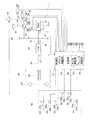
図2は、本発明の実施形態に係る作業車両1の構成を示す模式図である。図2に示すように、作業車両1は、エンジン21、PTO22、動力伝達装置24、走行装置25、操作装置26、制御部27などを備えている。
FIG. 2 is a schematic diagram showing the configuration of the
エンジン21は、例えばディーゼルエンジンである。エンジン21の出力は、エンジン21のシリンダ内に噴射する燃料量を調整することにより制御される。燃料量の調整は、エンジン21に取り付けられた燃料噴射装置21aを制御部27が制御することで行われる。作業車両1は、エンジン回転速度検出部31を備えている。エンジン回転速度検出部31は、エンジン回転速度を検出し、エンジン回転速度を示す検出信号を制御部27へ送る。
The
作業車両1は、作業機ポンプ23と、ステアリングポンプ28と、トランスミッションポンプ29とを有するとよい。作業機ポンプ23と、ステアリングポンプ28と、トランスミッションポンプ29とは、油圧ポンプである。PTO22は、これらの油圧ポンプ23、28、29に、エンジン21からの駆動力の一部を伝達する。すなわち、PTO22は、これらの油圧ポンプ23、28、29と、動力伝達装置24とにエンジン21からの駆動力を分配する。
The
作業機ポンプ23は、エンジン21からの駆動力によって駆動される。作業機ポンプ23から吐出された作動油は、作業機制御弁41を介して、上述したリフトシリンダ13とバケットシリンダ14とに供給される。作業車両1は、作業機ポンプ圧検出部32を備えている。作業機ポンプ圧検出部32は、作業機ポンプ23からの作動油の吐出圧(以下、「作業機ポンプ圧」と呼ぶ)を検出し、作業機ポンプ圧を示す検出信号を制御部27へ送る。
The
作業機ポンプ23は、可変容量型の油圧ポンプである。作業機ポンプ23の斜板或いは斜軸の傾転角が変更されることにより、作業機ポンプ23の吐出容量が変更される。作業機ポンプ23には、第1容量制御装置42が接続されている。第1容量制御装置42は、制御部27によって制御され、作業機ポンプ23の傾転角を変更する。これにより、作業機ポンプ23の吐出容量が制御部27によって制御される。例えば、第1容量制御装置42は、作業機制御弁41の前後での差圧が一定になるように、作業機ポンプ23の傾転角を調整する。また、第1容量制御装置42は、制御部27からの指令信号に応じて、作業機ポンプ23の傾転角を任意に変更することができる。詳細には、第1容量制御装置42は、図示しない第1バルブと第2バルブとを含む。上述した作業機制御弁41によって作業機3に供給される作動油が変更されると、作業機制御弁41の開度の変更に応じて作業機ポンプ23の吐出圧と作業機制御弁41の通過後の圧力との間に差圧が発生する。第1バルブは、制御部27によって制御されることで、作業機3の負荷が変動しても作業機制御弁41の前後での差圧を一定にするように作業機ポンプ23の傾転角を調整する。また、第2バルブは、制御部27によって制御されることで、作業機ポンプ23の傾転角をさらに変更することができる。作業車両1は、第1傾転角検出部33を備えている。第1傾転角検出部33は、作業機ポンプ23の傾転角を検出し、傾転角を示す検出信号を制御部27へ送る。
The
ステアリングポンプ28は、エンジン21からの駆動力によって駆動される。ステアリングポンプ28から吐出された作動油は、ステアリング制御弁43を介して、上述したステアリングシリンダ18に供給される。作業車両1は、ステアリングポンプ圧検出部35を備えている。ステアリングポンプ圧検出部35は、ステアリングポンプ28からの作動油の吐出圧(以下、「ステアリングポンプ圧」と呼ぶ)を検出し、ステアリングポンプ圧を示す検出信号を制御部27へ送る。
The
ステアリングポンプ28は、可変容量型の油圧ポンプである。ステアリングポンプ28の斜板或いは斜軸の傾転角が変更されることにより、ステアリングポンプ28の吐出容量が変更される。ステアリングポンプ28には、第2容量制御装置44が接続されている。第2容量制御装置44は、制御部27によって制御され、ステアリングポンプ28の傾転角を変更する。これにより、ステアリングポンプ28の吐出容量が制御部27によって制御される。作業車両1は、第2傾転角検出部34を備えている。第2傾転角検出部34は、ステアリングポンプ28の傾転角を検出し、傾転角を示す検出信号を制御部27へ送る。
The
トランスミッションポンプ29は、エンジン21からの駆動力によって駆動される。トランスミッションポンプ29は、固定容量型の油圧ポンプである。トランスミッションポンプ29から吐出された作動油は、後述するクラッチ制御弁VF、VR、VL、VHを介して動力伝達装置24のクラッチCF、CR、CL、CHに供給される。トランスミッションポンプ圧検出部36は、トランスミッションポンプ29からの作動油の吐出圧(以下、「トランスミッションポンプ圧」と呼ぶ)を検出し、トランスミッションポンプ圧を示す検出信号を制御部27へ送る。
The
PTO22は、エンジン21からの駆動力の一部を動力伝達装置24に伝達する。動力伝達装置24は、エンジン21からの駆動力を走行装置25に伝達する。動力伝達装置24は、エンジン21からの駆動力を変速して出力する。動力伝達装置24の構成については後に詳細に説明する。
The
走行装置25は、アクスル45と、走行輪4、5とを有する。走行装置25は、エンジン21によって駆動される。アクスル45は、動力伝達装置24からの駆動力を走行輪4、5に伝達する。これにより、走行輪4、5が回転する。作業車両1は、出力回転速度検出部37と入力回転速度検出部38とを備えている。出力回転速度検出部37は、動力伝達装置24の出力軸63の回転速度(以下、「出力回転速度」と呼ぶ)を検出する。出力回転速度は車速に対応しているため、出力回転速度検出部37は、出力回転速度を検出することで走行装置25の車速を検出する。入力回転速度検出部38は、動力伝達装置24の入力軸61の回転速度(以下、「入力回転速度」と呼ぶ)を検出する。出力回転速度検出部37は、出力回転速度を示す検出信号を制御部27に送る。入力回転速度検出部38は、入力回転速度を示す検出信号を制御部27に送る。
The traveling
なお、出力回転速度検出部37、入力回転速度検出部38に代えて、動力伝達装置24の内部の回転部品の回転速度を検出し、制御部27に送る回転速度検出部を別途設けて、制御部27がその回転部品の回転速度から入力回転速度、出力回転速度を算出してもよい。
In place of the output rotation
操作装置26は、オペレータによって操作される。操作装置26は、ブレーキ操作装置50と、アクセル操作装置51と、作業機操作装置52と、前後進切換操作装置54と、ステアリング操作装置57と、を有する。なお、操作装置26は、変速操作装置53をさらに有してもよい。
The operating
アクセル操作装置51は、アクセル操作部材51aと、アクセル操作検出部51bとを有する。アクセル操作部材51aは、エンジン21の目標回転速度を設定するために操作される。アクセル操作検出部51bは、アクセル操作装置51の操作量(以下、「アクセル操作量」と呼ぶ)を検出する。アクセル操作検出部51bは、アクセル操作量を示す検出信号を制御部27へ送る。
The
作業機操作装置52は、作業機操作部材52aと作業機操作検出部52bとを有する。作業機操作部材52aは、作業機3を動作させるために操作される。作業機操作検出部52bは、作業機操作部材52aの位置を検出する。作業機操作検出部52bは、作業機操作部材52aの位置を示す検出信号を制御部27に出力する。
The work
変速操作装置53は、変速操作部材53aと変速操作検出部53bとを有する。オペレータは、変速操作部材53aを操作することにより、動力伝達装置24の変速パターンを選択することができる。変速操作検出部53bは、変速操作部材53aの位置を検出する。変速操作検出部53bは、変速操作部材53aの位置を示す検出信号を制御部27に出力する。
The speed
前後進切換操作装置54は、前後進切換操作部材54aと前後進切換操作検出部54bとを有する。以降の説明では、前後進切換操作装置54をFR操作装置54と呼び、前後進切換操作部材54aをFR操作部材54aと呼び、前後進切換操作検出部54bをFR操作検出部54bと呼ぶ。FR操作装置54は、前進位置(F)と中立位置(N)と後進位置(R)とに選択的に切り換えられる。FR操作検出部54bは、FR操作部材54aの位置を検出する。FR操作検出部54bは、FR操作部材54aの位置を示す検出信号を制御部27に出力する。
The forward / reverse
ステアリング操作装置57は、ステアリング操作部材57aを有する。ステアリング操作装置57は、ステアリング操作部材57aの操作に基づきパイロット油圧をステアリング制御弁43に供給することにより、ステアリング制御弁43を駆動する。オペレータは、ステアリング操作部材57aを操作することにより、作業車両1の進行方向を左右に変更することができる。なお、ステアリング操作装置57はステアリング操作部材57aの操作を電気信号に変換してステアリング制御弁43を駆動してもよい。
The
ブレーキ操作装置50は、ブレーキ操作部材50aとブレーキ操作検出部50bとを有する。オペレータは、ブレーキ操作部材50aを操作することにより、ブレーキ装置を動作させて、作業車両1に制動力を生じさせる。ブレーキ操作検出部50bは、ブレーキ操作部材50aの位置を検出する。ブレーキ操作検出部50bは、ブレーキ操作部材50aの位置を示す検出信号を制御部27に出力する。ブレーキ操作部材50aは、後述するパーキングブレーキPBを作動させるために操作されるパーキングブレーキ操作部材も含む。パーキングブレーキ操作部材は、例えばパーキングスイッチ或いはパーキングレバーであり、オペレータによって操作される。パーキングブレーキPBは、パーキングブレーキ操作部材の操作に基づきパイロット油圧をパーキングブレーキ制御弁VBに供給することにより、パーキングブレーキ制御弁VBを駆動する。パーキングブレーキ操作部材が操作されると、操作信号が制御部27に出力される。
The
制御部27は、CPUなどの演算装置と、RAM及びROMなどのメモリとを有しており、作業車両1を制御するための各種の処理を行う。また、制御部27は、動力伝達装置24を制御するためのモータ制御部55及びクラッチ制御部58、ブレーキ操作装置50を操作するためのブレーキ制御部59、並びに、記憶部56を有する。動力伝達装置24の制御については後に詳細に説明する。記憶部56は、作業車両1を制御するための各種のプログラム及びデータを記憶している。
The
制御部27は、アクセル操作量に応じたエンジン21の目標回転速度が得られるように、指令スロットル値を示す指令信号を燃料噴射装置21aに送る。制御部27は、作業機操作検出部52bからの検出信号に基づいて作業機制御弁41を制御することにより、油圧シリンダ13、14に供給される油圧を制御する。これにより、油圧シリンダ13、14が伸縮して、作業機3が動作する。
The
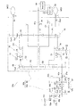
次に、動力伝達装置24の構成について詳細に説明する。図3は、動力伝達装置24の構成を示す模式図である。図3に示すように、動力伝達装置24は、入力軸61と、歯車機構62と、出力軸63と、第1モータMG1と、第2モータMG2と、キャパシタ64と、を備えている。動力伝達装置24では、第1モータMG1または第2モータMG2の回転速度が変化することによって、入力軸61に対する出力軸63の回転速度比が変化する。入力軸61は、上述したPTO22に接続されている。入力軸61には、PTO22を介してエンジン21からの回転が入力される。すなわち、入力軸61は、エンジンの出力軸と接続する。歯車機構62は、入力軸61の回転を出力軸63に伝達する。出力軸63は、上述した走行装置25に接続されており、歯車機構62からの回転を上述した走行装置25に伝達する。
Next, the configuration of the
歯車機構62は、エンジン21からの駆動力を伝達する機構である。歯車機構62によって、第1モータMG1または第2モータMG2の回転速度が変化すると、入力軸61に対する出力軸63の速度比が変化する。歯車機構62は、FR切換機構65と、変速機構66と、を有する。
The
FR切換機構65は、FクラッチCFと、RクラッチCRと、Fクラッチ出力軸61fと、Rクラッチ出力軸61rと、第1FクラッチギアGf1と、第2FクラッチギアGf2と、第1RクラッチギアGr1と、第2RクラッチギアGr2と、第3RクラッチギアGr3とを有している。FクラッチCFは、Fクラッチ出力軸61fと入力軸61(Fクラッチ入力軸)とを接続又は切断する。RクラッチCRは、Rクラッチ出力軸61rと入力軸61(Rクラッチ入力軸)とを接続又は切断する。Fクラッチ出力軸61fには、第1FクラッチギアGf1が接続している。Rクラッチ出力軸61rには、第1RクラッチギアGr1が接続している。第2FクラッチギアGf2は、伝達軸67に連結されており、第1FクラッチギアGf1と噛み合っている。第3RクラッチギアGr3は、伝達軸67に連結されており、第2RクラッチギアGr2と噛み合っている。第2RクラッチギアGr2は、第1RクラッチギアGr1と第3RクラッチギアGr3とに噛み合っている。第2FクラッチギアGf2及び第3RクラッチギアGr3は、後述する伝達軸67、第1サンギアS1、第1遊星ギアP1、第1リングギアR1、及び第1リング外周ギアGo1を介して第2モータMG2の出力軸に接続している。すなわち、Fクラッチ出力軸61f及びRクラッチ出力軸61rは、第1遊星歯車機構の少なくとも1つの回転要素を介して第2モータMG2の出力軸と接続する。
The
図3に示されている第1、第2FクラッチギアGf1、Gf2と、第1〜第3RクラッチギアGr1〜Gr3は、あくまで一例であり、FクラッチCFが接続される場合の伝達軸67の回転方向と、RクラッチCFが接続される場合の伝達軸67の回転方向とが互いに反対となっていれば、どのような構成であってもよい。
The first and second F clutch gears Gf1 and Gf2 and the first to third R clutch gears Gr1 to Gr3 shown in FIG. 3 are merely examples, and the rotation of the
FクラッチCFとRクラッチCRとは、油圧式クラッチであり、各クラッチCF、CRには、トランスミッションポンプ29からの作動油が供給される。FクラッチCFへの作動油は、Fクラッチ制御弁VFによって制御される。RクラッチCRへの作動油は、Rクラッチ制御弁VRによって制御される。各クラッチ制御弁VF、VRは、クラッチ制御部58からの指令信号によって制御される。FクラッチCFのオン(接続)/オフ(切断)とRクラッチCRのオン(接続)/オフ(切断)とが切り換えられることによって、FR切換機構65から出力される回転の方向が切り換えられる。つまり、FクラッチCFは、前進の向きに走行装置25を駆動させる歯車機構62(具体的には、第1FクラッチギアGf1)に接続される。RクラッチCRは後進の向きに走行装置25を駆動させる歯車機構62(具体的には、第1RクラッチギアGr1)に接続される。
The F clutch CF and the R clutch CR are hydraulic clutches, and hydraulic fluid from the
変速機構66は、伝達軸67と、第1遊星歯車機構68と、第2遊星歯車機構69と、Hi/Lo切換機構70と、出力ギア71と、を有している。伝達軸67は、FR切換機構65に連結されている。
The
第1遊星歯車機構68は、第1サンギアS1と、複数の第1遊星ギアP1と、複数の第1遊星ギアP1を支持する第1キャリアC1と、第1リングギアR1とを有している。第1サンギアS1は、伝達軸67に連結されている。ここで、説明の便宜上、FR切換機構65を介してエンジン21に接続する第1遊星歯車機構68の回転要素を第1回転要素と呼ぶ。つまり、第1サンギアS1は、第1回転要素に相当する。複数の第1遊星ギアP1は、第1サンギアS1と噛み合い、第1キャリアC1に回転可能に支持されている。第1キャリアC1の外周部には、第1キャリアギアGc1が設けられている。第1リングギアR1は、複数の第1遊星ギアP1に噛み合うとともに回転可能である。また、第1リングギアR1の外周には、第1リング外周ギアGo1が設けられている。
The first
第2遊星歯車機構69は、第2サンギアS2と、複数の第2遊星ギアP2と、複数の第2遊星ギアP2を支持する第2キャリアC2と、第2リングギアR2とを有している。第2サンギアS2は第1キャリアC1に連結されている。複数の第2遊星ギアP2は、第2サンギアS2と噛み合い、第2キャリアC2に回転可能に支持されている。第2リングギアR2は、複数の第2遊星ギアP2に噛み合うとともに回転可能である。第2リングギアR2の外周には、第2リング外周ギアGo2が設けられている。第2リング外周ギアGo2は出力ギア71に噛み合っており、第2リングギアR2の回転は出力ギア71を介して出力軸63に出力される。ここで、説明の便宜上、第2遊星歯車機構69の回転要素のうち、クラッチを介さずに、キャリアで直接第1遊星歯車機構68の回転要素と接続する回転要素を第4回転要素と呼ぶ。つまり、第2サンギアS2は、第4回転要素に相当する。また、出力軸63に接続される第2遊星歯車機構69の回転要素を第6回転要素と呼ぶ。つまり、第2リングギアR2は、第6回転要素に相当する。
The second
Hi/Lo切換機構70は、動力伝達装置24における駆動力伝達経路を第1モードと第2モードとで選択的に切り換えるための機構である。本実施形態において、第1モードは、速度比が低い場合に選択されるLoモードであり、第2モードは、速度比が高い場合に選択されるHiモードである。このHi/Lo切換機構70は、Hiモード時にオンにされるHクラッチCHと、Loモード時にオンにされるLクラッチCLとを有している。HクラッチCHは、第1リングギアR1と第2キャリアC2とを接続又は切断する。また、LクラッチCLは、第2キャリアC2と固定端72とを接続又は切断し、第2キャリアC2の回転を禁止又は許容する。ここで、説明の便宜上、LクラッチCL及びHクラッチCHに接続する第2遊星歯車機構69の回転要素を第5回転要素と呼ぶ。したがって、第2キャリアC2は、第5回転要素に相当する。
The Hi /
HクラッチCHは、第1リングギアR1と第2キャリアC2との接続によって第2キャリアC2(第5回転要素)の動きを制限するか、その接続を切断することによって第2キャリアC2(第5回転要素)の動きの制限を解除することができるように構成されている。また、LクラッチCLは、第2キャリアC2(第5回転要素)を固定するか、第2キャリアC2(第5回転要素)を解放することができるように構成されている。別の言い方をすれば、LクラッチCLは、第2キャリアC2と固定端72の接続によって第2キャリアC2(第5回転要素)の動きを制限するか、その接続を切断することによって第2キャリアC2(第5回転要素)の動きの制限を解除することができるように構成されている。このように、第5回転要素の動きを制限するか、第5回転要素の動きの制限を解除することができるように構成されているものを、本実施形態では、回転要素固定手段と呼ぶ。この定義によれば、HクラッチCH及びLクラッチCLは、回転要素固定手段である。
The H-clutch CH restricts the movement of the second carrier C2 (fifth rotating element) by connecting the first ring gear R1 and the second carrier C2, or disconnects the second carrier C2 (fifth carrier). The restriction of the movement of the rotating element) can be released. The L-clutch CL is configured to fix the second carrier C2 (fifth rotating element) or to release the second carrier C2 (fifth rotating element). In other words, the L-clutch CL is configured such that the movement of the second carrier C2 (fifth rotating element) is limited by the connection between the second carrier C2 and the
なお、HクラッチCHが切断され、LクラッチCLが接続されると、第2キャリアC2が固定されるため、第2遊星歯車機構69は、減速比一定のいわゆる減速機構と同等の動作を行う。したがって、第2遊星歯車機構69は無段変速の役割を果たさない。よって、Loモードにおいては、動力伝達装置24は、入力分割方式である。一方、LクラッチCLが切断され、HクラッチCHが接続されると、第1リングギアR1と第2キャリアC2とが接続されるため、第1遊星歯車機構68と第2遊星歯車機構69とが無段変速の役割を果たす。よって、Hiモードにおいては、動力伝達装置24は、複列方式である。
When the H clutch CH is disconnected and the L clutch CL is connected, the second carrier C2 is fixed, so that the second
なお、各クラッチCH、CLは油圧式クラッチであり、各クラッチCH、CLには、それぞれトランスミッションポンプ29からの作動油が供給される。HクラッチCHへの作動油は、Hクラッチ制御弁VHによって制御される。LクラッチCLへの作動油は、Lクラッチ制御弁VLによって制御される。各クラッチ制御弁VH、VLはクラッチ制御部58からの指令信号によって制御される。
Each clutch CH, CL is a hydraulic clutch, and hydraulic oil from the
第1モータMG1及び第2モータMG2は、電気エネルギーによって駆動力を発生させる駆動モータとして機能する。また、第1モータMG1及び第2モータMG2は、入力される駆動力を用いて電気エネルギーを発生させるジェネレータとしても機能する(以降の説明では、このようなモータをエネルギー生成用モータとも呼ぶ)。第1モータMG1の駆動時の回転方向と逆方向に第1モータMG1が回転する場合は、第1モータMG1はジェネレータとして機能する。第1モータMG1の出力軸には第1モータギアGm1が固定されており、第1モータギアGm1は第1キャリアギアGc1に噛み合っている。つまり、第1モータMG1は、第1遊星歯車機構68の第1キャリアC1に接続されている。第1モータMG1は、FクラッチCF及びRクラッチCRが切断され、第1遊星歯車機構68の第1リングギアR1が固定されたときに、Fクラッチ出力軸61f及びRクラッチ出力軸61rの回転速度を制御することができる。また、エンジン21は、第1遊星歯車機構68の第1リングギアR1が固定されたときに、第1モータMG1の回転軸を回転させることができる。
The first motor MG1 and the second motor MG2 function as driving motors that generate driving force by electric energy. The first motor MG1 and the second motor MG2 also function as generators that generate electrical energy using the input driving force (in the following description, such motors are also referred to as energy generation motors). When the first motor MG1 rotates in the direction opposite to the rotation direction when the first motor MG1 is driven, the first motor MG1 functions as a generator. A first motor gear Gm1 is fixed to the output shaft of the first motor MG1, and the first motor gear Gm1 meshes with the first carrier gear Gc1. That is, the first motor MG1 is connected to the first carrier C1 of the first
ここで、説明の便宜上、第1モータMG1と第2モータMG2とのうち、駆動モータとして機能するモータと接続する第1遊星歯車機構68の回転要素を第2回転要素と呼ぶ。第1モータMG1と第2モータMG2とのうち、ジェネレータとして機能するモータと接続する第1遊星歯車機構68の回転要素を第3回転要素と呼ぶ。第1モータMG1が駆動モータとして機能する場合、第1キャリアC1は、第2回転要素に相当する。第1モータMG1がジェネレータとして機能する場合、第1キャリアC1は、第3回転要素に相当する。上述する第1回転要素〜第3回転要素の定義によれば、第1回転要素、第2回転要素、第3回転要素は互いに異なる要素である。同様に、第4回転要素、第5回転要素、第6回転要素は互いに異なる要素である。また、第2遊星歯車機構69の第4回転要素(サンギアS2)は、第1遊星歯車機構68の第2回転要素及び第3回転要素のうちの一方に接続されることが言える。
Here, for convenience of explanation, the rotating element of the first
第1モータMG1にはインバータ60が接続されており、このインバータ60に、第1モータMG1のモータトルクを制御するための指令信号がモータ制御部55から与えられる。インバータ60の詳細な構成については後述する。第1モータMG1の回転速度は、第1モータ回転速度検出部75によって検出される。第1モータ回転速度検出部75は、第1モータMG1の回転速度を示す検出信号を制御部27に送る。
An
第2モータMG2は、第1モータMG1と同様の構成である。第2モータMG2の出力軸には第2モータギアGm2が固定されており、第2モータギアGm2は第1リング外周ギアGo1に噛み合っている。つまり、第2モータMG2は、第1遊星歯車機構68の第1リング外周ギアGo1(つまり、第1リングギアR1)に接続されている。上述の定義によると、第2モータMG2が駆動モータとして機能する場合、第1リングギアR1は、第2回転要素に相当する。第2モータMG2がジェネレータとして機能する場合、第1リングギアR1は、第3回転要素に相当する。第2モータMG2は、第1遊星歯車機構68の第1キャリアC1が固定されたときに、Fクラッチ出力軸61f及びRクラッチ出力軸61rの回転速度を制御することができる。また、エンジン21は、第1遊星歯車機構68の第1キャリアC1が固定されたときに、第2モータMG2の回転軸を回転させることができる。
The second motor MG2 has the same configuration as the first motor MG1. A second motor gear Gm2 is fixed to the output shaft of the second motor MG2, and the second motor gear Gm2 meshes with the first ring outer peripheral gear Go1. That is, the second motor MG2 is connected to the first ring outer peripheral gear Go1 (that is, the first ring gear R1) of the first
第1モータMG1、第2モータMG2は、駆動モータとして機能し、回転速度が0になるように制御されると、それぞれ、第1キャリアC1、第1リング外周ギアGo1(つまり、第1リングギアR1)を固定することができる。以降の説明では、このように、第1遊星歯車機構の第2回転要素に接続するモータを、接続モータとも呼ぶ。さらに、第1遊星歯車機構68の第2回転要素を固定または解放するための回転要素を制御用回転要素と呼び、第2回転要素を固定または解放するものを固定手段と呼ぶ。したがって、固定手段は、接続モータ(第1モータMG1または第2モータMG2)を含む。また、第1モータMG1の回転速度を0とすることによって、第1キャリアC1(第2回転要素)を固定する場合、第1モータMG1の回転軸が制御用回転要素に相当する。第2モータMG2の回転速度を0とすることによって、第1リングギアR1(第2回転要素)を固定する場合、第2モータMG2の回転軸が制御用回転要素に相当する。なお、制御用回転要素は、第2回転要素と接続モータとの間の少なくとも1つの回転要素であってもよい。
The first motor MG1 and the second motor MG2 function as drive motors. When the rotation speed is controlled to be zero, the first carrier C1 and the first ring outer peripheral gear Go1 (that is, the first ring gear), respectively. R1) can be fixed. In the following description, the motor connected to the second rotating element of the first planetary gear mechanism is also referred to as a connection motor. Further, the rotating element for fixing or releasing the second rotating element of the first
第2モータMG2にはインバータ60が接続されており、インバータ60に、第2モータMG2のモータトルクを制御するための指令信号がモータ制御部55から与えられる。本実施形態では、インバータ60は、第1モータMG1と第2モータMG2との両方の駆動に使用される一体型インバータを例示しているが、第1モータMG1と第2モータMG2とのそれぞれに対して、別々のインバータが使用されてもよい。インバータ60の詳細な構成については後述する。第2モータMG2の回転速度は、第2モータ回転速度検出部76によって検出される。第2モータ回転速度検出部76は、第2モータMG2の回転速度を示す検出信号を制御部27に送る。
An
キャパシタ64は、モータMG1、MG2の少なくとも一方で発生するエネルギーを蓄えるエネルギー貯留部として機能する。すなわち、キャパシタ64は、各モータMG1、MG2の合計発電量が各モータMG1、MG2の合計電力消費量より大きいときに、各モータMG1、MG2で発電された電力を蓄電する。また、キャパシタ64は、各モータMG1、MG2の合計電力消費量が各モータMG1、MG2の合計発電量より大きいときに、電力を放電する。すなわち、各モータMG1、MG2は、キャパシタ64に蓄えられた電力によって駆動される。キャパシタ64とインバータ60との間には、変圧器86(図4参照)が設けられる。変圧器86については後述する。なお、制御部27は、現在キャパシタ64に蓄えられているエネルギーを監視し、監視結果を後述する各種制御に利用することができる。また、キャパシタ64に代えて、バッテリーが他の蓄電手段として用いられてもよい。ただし、キャパシタ64は、バッテリー等の他の蓄電手段に比べて、高速充電/高速放電を行うことができる。作業車両1は短時間で前進・後進を切り換えるシャトル動作を行うことがあるため、効率的に充放電できる点で、キャパシタがバッテリーよりも作業車両1のエネルギー貯留部として適している。
なお、キャパシタとバッテリーでは、蓄積されている電気の大きさを表す表現が異なる。例えば、キャパシタでは電圧によって表現することが一般的であるが、バッテリーではアンペア・アワー(Ah)によって表現することが一般的である。本実施形態では、エネルギー貯留部が蓄える電気の大きさを電気の量又は電気量と表現し、電気の量又は電気量を上述した概念を包含するものとして用いる。 It should be noted that the capacitor and the battery have different expressions representing the stored electricity. For example, the capacitor is generally expressed by voltage, but the battery is generally expressed by ampere hour (Ah). In the present embodiment, the amount of electricity stored in the energy storage unit is expressed as the amount of electricity or the amount of electricity, and the amount of electricity or the amount of electricity is used as including the concept described above.
モータ制御部55は、一般的には、各種の検出部からの検出信号を受けて、モータMG1、MG2への指令トルクまたは指令回転速度を示す指令信号をインバータ60に与える。ただし、本実施形態では、モータ制御部55は、エンジン21による駆動によって入力軸61(FクラッチCFの入力軸及びRクラッチCRの入力軸)の回転速度に近づけるように、Fクラッチ出力軸61f及びRクラッチ出力軸61rの回転速度を調整する回転速度調整部を含む。
In general, the
また、クラッチ制御部58は、一般的には、各クラッチCF、CR、CH、CLのクラッチ油圧を制御するための指令信号を各クラッチ制御弁VF、VR、VH、VLに与える。ただし、本実施形態では、クラッチ制御部58は、FクラッチCFまたはRクラッチCRを滑らしながら係合させることによって、入力軸61(FクラッチCFの入力軸及びRクラッチCRの入力軸)と、Fクラッチ出力軸61f及びRクラッチ出力軸61rとの回転速度を調整する回転速度調整部を含む。
Further, the
動力伝達装置24は、パーキングブレーキPBと、パーキングブレーキ制御弁VBとをさらに備えている。パーキングブレーキPBは、制動状態と非制動状態とに切り換えられる。パーキングブレーキPBは、制動状態において、出力軸63を制動する。パーキングブレーキPBは、非制動状態において、出力軸63を解放する。LクラッチCLが接続している(第2遊星歯車機構69の第5回転要素が固定されている)とき、パーキングブレーキPBが出力軸63を制動すると、第1キャリアC1(第1遊星歯車機構68の第2回転要素)を固定する。したがって、パーキングブレーキPBは、上述する固定手段に含まれる。
The
パーキングブレーキ制御弁VBは、ブレーキ制御部59(つまり、制御部27)からの指令信号に基づいて制御される電磁制御弁である。ブレーキ制御部59は、パーキングブレーキ制御弁VBを制御することによって、パーキングブレーキPBを制動状態と非制動状態とに切り換える。通常、パーキングブレーキPBは、パーキングブレーキ操作部材の操作に応じて制動状態と非制動状態とに切り換えられる。ただし、ブレーキ制御部59は、パーキングブレーキ操作部材の操作がなくても、所定の要件を満たす場合、パーキングブレーキPBを制動状態または非制動状態に切り換えることができる。この所定の要件の詳細については後述する。
The parking brake control valve VB is an electromagnetic control valve that is controlled based on a command signal from the brake control unit 59 (that is, the control unit 27). The
パーキングブレーキPBは、ブレーキディスク部73aとピストン部73bとを有している。ピストン部73bに作動油が供給されると、ピストン部73bが油圧によってブレーキディスク部73aの複数のブレーキディスクを互いに接触させる。これにより、パーキングブレーキPBが制動状態となる。また、ピストン部73bから作動油が排出されると、ピストン部73bに設けられた弾性部材の弾性力によってブレーキディスクが互いに非接触の状態に保持される。これにより、パーキングブレーキPBが非制動状態となる。
The parking brake PB has a
図4は、インバータ60の詳細な内部構成と、インバータ60とモータMG1、MG2、キャパシタ64との接続関係について示した図である。インバータ60は、第1モータMG1に対する出力端子と、第2モータMG2に対する出力端子をともに有する一体型インバータである。インバータ60は、第1出力端子81、第2出力端子82、第1内部インバータ83、第2内部インバータ84、第1コンデンサ85、変圧器86、第2コンデンサ87、メインコンタクタ88、及び、抵抗器付きコンタクタ89を含む。
FIG. 4 is a diagram showing a detailed internal configuration of
第1出力端子81は、第1モータMG1と第1内部インバータ83とを接続する。第1出力端子81は、好ましくは、第1モータMG1を制御するための三相出力端子を有する。第2出力端子82は、第2モータMG2と第2内部インバータ84とを接続する。第2出力端子82は、好ましくは、第2モータMG2を制御するための三相出力端子を有する。
The
第1内部インバータ83は、モータ制御部55からの第1モータMG1に関する指令信号に基づいて、第1モータMG1に出力する可変電圧・可変周波数の駆動信号を出力する。第1内部インバータ83は、キャパシタ64により構成される単一の電源から、第1モータMG1を時計回りに回転させるための駆動信号と第1モータMG1を反時計回りに回転させるための駆動信号の両方を出力することができる。また、第1内部インバータ83は、第1モータMG1が回転されることにより生じる逆起電力を直流電圧に変換し、変圧器86を介してキャパシタ64に出力する。第1モータMG1が時計回り/半時計周りのいずれに回転されても、インバータ83の各端子から同じ極性の電圧が変圧器86を介してキャパシタ64へ向けて出力される。
The first
第2内部インバータ84は、モータ制御部55からの第2モータMG2に関する指令信号に基づいて、第2モータMG2に出力する可変電圧・可変周波数の駆動信号を出力する。第2内部インバータ84は、キャパシタ64により構成される単一の電源から、第2モータMG2を時計回りに回転させるための駆動信号と第2モータMG2を反時計回りに回転させるための駆動信号の両方を出力することができる。また、第2内部インバータ84は、第2モータMG2が回転されることにより生じる逆電力を直流電圧に変換し、変圧器86を介してキャパシタ64に出力する。第2モータMG2が時計回り/半時計周りのいずれに回転されても、インバータ83の各端子から同じ極性の電圧が変圧器86を介してキャパシタ64へ向けて出力される。
The second
第1コンデンサ85及び第2コンデンサ87は、リップル(突入電流)防止の目的で設けられ、それらの容量は、キャパシタ64に比べてはるかに小さく、電力授受には寄与しない。変圧器86は、IGBT(Insulated Gate Bipolar Transistor)を含む。変圧器86は、IGBTのON/OFFを調整することによって、キャパシタ64側の電圧を変圧器86と各インバータ83、84との間の系統間の電圧(例えば、550V)に変換する。あるいは、変圧器86は、IGBTのON/OFFを調整することによって、変圧器86と各インバータ83、84との間の系統間の電圧をキャパシタ64側の電圧に変換する。ここで、キャパシタ64側の電圧を1次電圧とも呼び、変圧器86と各インバータ83、84との間の系統間の電圧を2次電圧とも呼ぶこととする。
The
メインコンタクタ88は、電磁接触器(Electromagnetic Contactor)であり、キャパシタ64の電力を変圧器86に送る、もしくは、モータMG1,MG2によって発電された電力を、変圧器86を経由してキャパシタ64に送るためのものである。抵抗器付きコンタクタ89は、電磁接触器に加えて抵抗Rを有している。抵抗器付きコンタクタ89は、モータMG1,MG2による充電を開始する前の準備段階で使用させる。抵抗器付きコンタクタ89の使用方法の詳細については後述する。
The
本実施形態では、制御部27は、第1遊星歯車機構68の第1キャリアC1を固定し、エンジン21と伝達軸67との回転速度を近づけるように調整する。これにより、係合する回転軸の回転速度の差を小さくする。そして、制御部27は、当該2つの回転軸の回転速度の差が所定の範囲内となった後に第1クラッチを係合させ、エンジン21の駆動力により第2モータMG2を回転させることによってキャパシタ64を充電する。つまり、制御部27は、エネルギー貯留部にエネルギーを蓄える。以下に、本実施形態に係る動力伝達装置24の概略動作を、図5A〜5Cを利用して説明する。図5A〜5Cは、第1の実施形態の動力伝達装置24の概略動作を示すフローチャートである。図5A〜5Cでは、パーキングブレーキPBを係合することによる充電方法をステップS60以降で説明する。モータの回転速度を制御し、クラッチ間の同期をとることによる充電方法をステップS70以降で説明する。エンジン回転を利用し、クラッチモジュレーションを行うことによりクラッチを係合させる充電方法をステップS130以降で説明する。下記に示す動力伝達装置24の動作は、作業車両1の起動時や、FR操作装置54が中立位置(N)に設定されている場合に実行される。
In the present embodiment, the
ステップS10において、制御部27は、キャパシタ64の電圧Vcapが充電開始閾値Vchg_sより低いか否か判定する。キャパシタ電圧Vcapが充電開始閾値Vchg_s以上である場合(ステップS10でNo)、制御部27は本制御を終了させる(図5A及び図5C参照)。キャパシタ電圧Vcapが充電開始閾値Vchg_sより低い場合(ステップS10でYes)、制御部27は、キャパシタ電圧Vcapがキャリア回転制御閾値Vlst2より高いか否か判定する(ステップS20)。キャパシタ電圧Vcapがキャリア回転制御閾値Vlst2以下である場合、第1モータMG1を制御して第1キャリアC1を固定するために十分な電力がキャパシタ64にないことを意味する。
In step S10, the
キャパシタ電圧Vcapがキャリア回転制御閾値Vlst2より高い場合(ステップS20でYes)、制御部27は、FクラッチCF及びRクラッチCRがともにリリース(解放)されており、且つ、エンジン回転速度Nengが所定の回転速度Nliより大きいか否かを判定する(ステップS30)。回転速度Nliは、アクセルオフ、且つ無負荷のときのエンジン21の回転速度付近の値である。FクラッチCFまたはRクラッチCRのいずれかが接続されているか、或いは、エンジン回転速度Nengが所定の回転速度Nli以下である場合(ステップS30でNo)、制御部27は本制御を終了させる(図5A及び図5C参照)。FクラッチCF及びRクラッチCRがともにリリースされており、且つ、エンジン回転速度Nengが所定の回転速度Nliより大きい場合(ステップS30でYes)、制御部27(モータ制御部55)は、第1モータMG1の回転速度を0rpmとするように第1モータMG1を制御する(ステップS41)。すなわち、モータ制御部55は、第1モータMG1の回転速度を0rpmとするための指令信号をインバータ60に与える。つまり、モータ制御部55は、第1モータMG1(接続モータ)の回転速度Nm1を0rpmとするように第1モータMG1を制御する。つまり、制御部27は、第2回転要素(第1キャリアC1)に接続する制御用回転要素(この場合、第1モータMG1の回転軸)を固定する制御を行うことによって、第1遊星歯車機構68の第2回転要素を固定する。別の言い方をすれば、固定手段は、第1遊星歯車機構68の第2回転要素を固定する。
When the capacitor voltage Vcap is higher than the carrier rotation control threshold value Vlst2 (Yes in step S20), the
つぎに、ステップS42において、制御部27(クラッチ制御部58)は、HクラッチCH及びLクラッチCLがともにリリース(解放)されるように、Hクラッチ制御弁VH及びLクラッチ制御弁VLを制御する。つまり、クラッチ制御部58は、HクラッチCH及びLクラッチCLをともにリリースする指令信号を、Hクラッチ制御弁VH及びLクラッチ制御弁VLに出力する。別の言い方をすれば、制御部27(クラッチ制御部58)は、回転要素固定手段(HクラッチCH及びLクラッチCL)に、第2遊星歯車機構69の第5回転要素の動きの制限を解除させている。さらに、ステップS42において、制御部27(ブレーキ制御部59)は、パーキングブレーキPBがリリースされる(非制動状態とされる)ように、パーキングブレーキ制御弁VBを制御する。すなわち、ブレーキ制御部59は、パーキングブレーキPBをリリースする指令信号を、パーキングブレーキ制御弁VBに出力する。これにより、出力軸63は自由に回転できるので、作業車両1は、ニュートラルにおける一般的な車両の動作と同じ動作を行う。つまり、作業車両1が走行状態にある場合にステップS42の動作が実行されると、作業車両1は、慣性によって走行を行う。また、作業車両1が傾斜面上に位置するときは、重力の斜面に平行な方向の成分が動力伝達装置24等の作業車両1内部の摩擦力よりも大きいときは、作業車両1は斜面を下る方向に加速する。
Next, in step S42, the control unit 27 (clutch control unit 58) controls the H clutch control valve VH and the L clutch control valve VL so that both the H clutch CH and the L clutch CL are released (released). . That is, the
ステップS42の終了後、制御部27は、PB充電フラグをFalseにセット(set)する(ステップS43)。PB充電フラグはBoolean型の変数であり、この値がTrueであると、後述するステップS60においてパーキングブレーキPBが係合された状態で充電されることを意味する。
After the end of step S42, the
一方、キャパシタ電圧Vcapがキャリア回転制御閾値Vlst2以下である場合(ステップS20でNo)、制御部27は、ステップS30の条件に加えて、さらに車速Vsが0となっているか否かを判定する(ステップS50)。ステップS50の条件を満たさない場合(ステップS50でNo)、制御部27は本制御を終了させる(図5A及び図5C参照)。逆にステップS50の条件を満たす場合(ステップS50でYes)、ステップS60において、制御部27(クラッチ制御部58)は、LクラッチCLを係合させ、HクラッチCHをリリースさせるように、Lクラッチ制御弁VL及びHクラッチ制御弁VHを制御する。つまり、クラッチ制御部58は、LクラッチCLを係合させる指令信号をLクラッチ制御弁VLに出力し、HクラッチCHをリリースする指令信号をHクラッチ制御弁VHに出力する。さらに、ステップS60において、制御部27(ブレーキ制御部59)は、パーキングブレーキPBを係合する(制動状態とされる)ように、パーキングブレーキ制御弁VBを制御する。すなわち、ブレーキ制御部59は、パーキングブレーキPBを係合する指令信号を、パーキングブレーキ制御弁VBに出力する。これにより、制御部27は、第1遊星歯車機構68の第1キャリアC1を固定する。別の言い方をすれば、固定手段は、第1遊星歯車機構68の第2回転要素を固定する。この場合、出力軸63はパーキングブレーキPBにより固定されるので、作業車両1は、停止する。ステップS60の終了後、制御部27は、PB充電フラグをTrueにセットする(ステップS61)。
On the other hand, when the capacitor voltage Vcap is equal to or lower than the carrier rotation control threshold value Vlst2 (No in step S20), the
ステップS43又はステップS61が終了後、図5BのステップS70において、制御部27は、キャパシタ電圧Vcapがクラッチ同期制御閾値Vlst1より高いか否か判定する。キャパシタ電圧Vcapがクラッチ同期制御閾値Vlst1以下である場合、第2モータMG2を制御してFクラッチCF又はRクラッチCRの入力軸と出力軸とを同期させるために十分な電力がキャパシタ64にないことを意味する。キャパシタ電圧Vcapがクラッチ同期制御閾値Vlst1以下である場合(ステップS70でNo)、後述するステップS130に進む。キャパシタ電圧Vcapがクラッチ同期制御閾値Vlst1より大きい場合(ステップS70でYes)、制御部27(モータ制御部55、回転速度調整部)は、FクラッチCF又はRクラッチCRの入力軸61の回転速度に対する出力軸61f,61rの回転速度(FクラッチCF又はRクラッチCRの相対回転速度)を0に近づけるように、第2モータMG2の回転速度Nm2を制御する(ステップS80)。つまり、制御部27(モータ制御部55)は、FクラッチCF又はRクラッチCRの出力軸61f,61rの回転速度を、FクラッチCF又はRクラッチCRの入力軸61の回転速度と一致するように、第2モータMG2を制御する。
After step S43 or step S61 ends, in step S70 of FIG. 5B, the
つぎに、第2モータMG2の制御中に、制御部27は、キャパシタ電圧Vcapがクラッチ同期制御閾値Vlst1より高いか否か判定する(ステップS90)。もし、キャパシタ電圧Vcapがクラッチ同期制御閾値Vlst1以下となれば(ステップS90でNo)、第2モータMG2の回転速度Nm2の制御を中止し(ステップS100)、ステップS70へ戻る。キャパシタ電圧Vcapがクラッチ同期制御閾値Vlst1より高い場合(ステップS90でYes)、制御部27は、FクラッチCFの相対回転速度RSfの絶対値が所定の閾値Rth(ただし、Rthは正の値)より下回っているか、もしくは、RクラッチCRの相対回転速度RSrの絶対値が所定の閾値Rthより下回っているかどうか判定する(ステップS110)。なお、ステップS110においては、制御部27は、−Rth<RSf<Rthであるか、または、−Rth<RSr<Rthであるかを判定してもよい。
Next, during the control of the second motor MG2, the
FクラッチCFの相対回転速度RSfの絶対値及びRクラッチCRの相対回転速度RSrの絶対値がともに所定の閾値Rth以上である場合(ステップS110でNo)、ステップS80に進む。FクラッチCFの相対回転速度RSfの絶対値及びRクラッチCRの相対回転速度RSrの絶対値の少なくとも一方が所定の閾値Rthより小さい場合(ステップS110でYes)、制御部27(クラッチ制御部58)は、相対回転速度がRthより小さくなったクラッチである第1クラッチを滑らないように係合するように、第1クラッチのクラッチ制御弁を制御する(ステップS120)。すなわち、クラッチ制御部58は、第1クラッチを滑らないように係合するための指令信号を第1クラッチのクラッチ制御弁に出力する。つまり、クラッチ制御部58(回転速度調整部)は、第1クラッチの2つの回転軸の回転速度を近づけて第1クラッチを係合させる。これにより、第1クラッチの回転速度の差を減らした上で第1クラッチを係合させるので、第1クラッチの磨耗が軽減される。なお、このときの第1クラッチのクラッチ圧を係合圧と呼ぶ。
If the absolute value of the relative rotational speed RSf of the F clutch CF and the absolute value of the relative rotational speed RSr of the R clutch CR are both greater than or equal to a predetermined threshold Rth (No in step S110), the process proceeds to step S80. When at least one of the absolute value of the relative rotational speed RSf of the F-clutch CF and the absolute value of the relative rotational speed RSr of the R-clutch CR is smaller than a predetermined threshold Rth (Yes in step S110), the control unit 27 (clutch control unit 58) Controls the clutch control valve of the first clutch so that the first clutch, which is a clutch having a relative rotational speed smaller than Rth, is engaged without slipping (step S120). That is, the
一方、キャパシタ電圧Vcapがクラッチ同期制御閾値Vlst1以下である場合(ステップS70でNo)、制御部27(クラッチ制御部58)は、第1クラッチのクラッチ圧を所定の増分だけ増加させるように、第1クラッチのクラッチ制御弁を制御する(ステップS130)。つまり、クラッチ制御部58は、第1クラッチのクラッチ圧を所定の増分だけ増加させる指令信号を第1クラッチのクラッチ制御弁に出力する。制御部27(クラッチ制御部58)は、第1クラッチのクラッチ圧を増加させることによって、第1クラッチの2つの回転軸を滑らしながら接続させる。これによって、制御部27(クラッチ制御部58)は、第1クラッチの2つの回転軸の回転速度を近づける。そして、制御部27(クラッチ制御部58)は、第1クラッチが係合したかどうか判定する(ステップS140)。具体的には、制御部27(クラッチ制御部58)は、第1クラッチのクラッチ圧が係合圧に達したかどうかを判定する。クラッチ制御部58が第1クラッチのクラッチ制御弁に出力する指令信号の電流の大きさなどによって係合圧に達したかどうかを判定してもよい。第1クラッチが係合しているときは、第1クラッチの2つの回転軸の回転速度が一致している。すなわち、第1クラッチの2つの回転軸の回転速度が一致した後に、制御部27(クラッチ制御部58)は、第1クラッチを滑らないように接続させている。
On the other hand, when the capacitor voltage Vcap is equal to or lower than the clutch synchronization control threshold value Vlst1 (No in step S70), the control unit 27 (clutch control unit 58) increases the clutch pressure of the first clutch by a predetermined increment. A clutch control valve for one clutch is controlled (step S130). That is, the
第1クラッチのクラッチ圧が係合圧に達していない場合(ステップS140でNo)、制御部27は、エンジン回転速度Nengが所定の回転速度Npseより下回っていないか否か判定する(ステップS150)。回転速度Npseより小さい回転速度は、クラッチを係合した場合、後述するエンジン回転速度Nstpまで減少する可能性の高い回転速度である。エンジン回転速度Nengが所定の回転速度Npse以上である場合(ステップS150でNo)、ステップS130に戻る。エンジン回転速度Nengが所定の回転速度Npseより下回っている場合(ステップS150でYes)、制御部27は、エンジン回転速度Nengが所定の回転速度Nstpより下回っていないか否か判定する(ステップS160)。回転速度Nstpより小さい回転速度は、エンジン21が停止(stall)する回転速度まで減少する恐れが高い回転速度である。
When the clutch pressure of the first clutch has not reached the engagement pressure (No in Step S140), the
エンジン回転速度Nengが所定の回転速度Nstp以上である場合(ステップS160でNo)、制御部27(クラッチ制御部58)は、第1クラッチのクラッチ圧を維持するように第1クラッチのクラッチ制御弁を制御する(ステップS170)。すなわち、クラッチ制御部58は、第1クラッチのクラッチ圧を維持する指令信号を第1クラッチのクラッチ制御弁に出力する。エンジン回転速度Nengが所定の回転速度Nstpを下回った場合(ステップS160でYes)、制御部27(クラッチ制御部58)は、第1クラッチをリリースするように第1クラッチのクラッチ制御弁を制御する(ステップS180)。すなわち、クラッチ制御部58は、第1クラッチをリリースする指令信号を第1クラッチのクラッチ制御弁に出力する。
When the engine rotational speed Neng is equal to or higher than the predetermined rotational speed Nstp (No in step S160), the control unit 27 (clutch control unit 58) controls the clutch control valve of the first clutch so as to maintain the clutch pressure of the first clutch. Is controlled (step S170). That is, the
ステップS170又はS180の終了後、制御部27は、エンジン回転速度Nengが回転速度Nliより上回ったかどうか判定する(ステップS190)。エンジン回転速度Nengが回転速度Nliより上回った場合(ステップS190でYes)、ステップS130に戻る。エンジン回転速度Nengが回転速度Nli以下である場合(ステップS190でNo)、ステップS160に戻る。
After step S170 or S180 ends, the
第1クラッチが滑らないように接続すると(ステップS120の後、若しくは、ステップS140でYesのとき)、制御部27は、エンジン21の駆動力により第2モータMG2を回転させることによってキャパシタ64を充電する動作(S200)を開始する。図6は、キャパシタの充電の際にインバータが行う動作の詳細を示すフローチャートである。
When the first clutch is connected so as not to slip (after step S120 or when step S140 is Yes), the
この動作では、まず、制御部27からの指令信号に基づき、インバータ60は、抵抗器付きコンタクタ89を接続する(S201)。コンタクタ88、89が共に切断されている際に、分岐点A,Bで電位差が生じていると、いきなりメインコンタクタ88を接続してしまうと、キャパシタ64に大量の電流が流れる恐れがある。したがって、キャパシタ64に流れる電流の量を小さくするために、インバータ60は抵抗器付きコンタクタ89を接続する。
In this operation, first, based on a command signal from the
抵抗器付きコンタクタ89を接続することによって、分岐点AとBとの電位差がなくなると、制御部27からの指令信号に基づき、インバータ60はメインコンタクタ88を接続し(ステップS202)、抵抗器付きコンタクタ89を切断する(ステップS203)。そして、制御部27は、キャパシタ電圧Vcapが所定の電圧Vchg_thより大きいかどうかを判定する(ステップS204)。この所定の電圧Vchg_thは、後述するステップS210において、第2モータMG2に対し、エンジン21による回転を妨げる方向にトルクを発生させるための駆動信号を、インバータ60が発生するために必要な電圧である。
When the potential difference between the branch points A and B disappears by connecting the
キャパシタ電圧Vcapが所定の電圧Vchg_th以下である場合(ステップS204でNo)、制御部27からの指令信号に基づき、インバータ60は変圧器86のIGBTを起動し、第2モータMG2がエンジン21によって回転させられることにより生じる逆起電力をキャパシタ64に充電させる(ステップS205)。つぎに、制御部27は、PB充電フラグがTrueであり、且つ、キャパシタ電圧Vcapが所定の電圧Vlst3より大きいか否かを判定する(ステップS206)。PB充電フラグがFalseであるか、キャパシタ電圧Vcapが所定の電圧Vlst3以下である場合(ステップS206でNo)、ステップS204に戻る。PB充電フラグがTrueであり、且つ、キャパシタ電圧Vcapが所定の電圧Vlst3より大きい場合(ステップS206でYes)、クラッチ制御部58は、LクラッチCL及びパーキングブレーキPBをともにリリースする指令信号を、Lクラッチ制御弁VL及びパーキングブレーキ制御弁VBに出力する(ステップS207)。つまり、制御部27(クラッチ制御部58)は、回転要素固定手段(HクラッチCH及びLクラッチCL)に、第2遊星歯車機構69の第5回転要素の動きの制限を解除させている。つぎに、ステップS208において、モータ制御部55は、第1モータMG1の回転速度を0rpmとするための指令信号をインバータ60に与える。つまり、モータ制御部55は、第1モータMG1の回転速度を0rpmとするように第1モータMG1を制御する。つまり、制御部27は、第2回転要素に接続する制御用回転要素(第1モータMG1の回転軸)を固定する制御を行うことによって、第1遊星歯車機構68の第1キャリアC1を固定する。これにより、作業車両1は、ニュートラルにおける一般的な車両の動作と同じ動作を行う。ステップS208の終了後、制御部27は、PB充電フラグをFalseにセットする(ステップS209)。
When the capacitor voltage Vcap is equal to or lower than the predetermined voltage Vchg_th (No in step S204), the
ステップS209が終了すると、ステップS204に戻る。キャパシタ電圧Vcapが所定の電圧Vchg_thより大きい場合(ステップS204でYes)、ステップS210において、制御部27は、エンジン21による回転を妨げる方向に第2モータMG2のトルクを発生させるための指令信号をインバータ60(第2内部インバータ84)に出力する。つまり、キャパシタ64を充電する際に、エンジン21の駆動力による回転を妨げる方向に第2モータMG2のトルクを発生させるように、キャパシタ64に蓄えられた電気によって第2モータMG2を駆動する。これによって、第2モータMG2が出力する逆起電力がより大きくなる。したがって、ステップS206において、インバータ60は、変圧器86のIGBTを起動し、より大きい逆起電力をキャパシタ64に充電させることができる。
When step S209 ends, the process returns to step S204. When the capacitor voltage Vcap is larger than the predetermined voltage Vchg_th (Yes in step S204), in step S210, the
図5Cに戻り、制御部27は、オペレータからの所定の操作があるかどうか判定する(ステップS215)。所定の操作とは、例えば、FR操作部材54aを中立位置(N)から他の位置(FもしくはR)に移動させる動作や、アクセル操作部材51aを踏む動作である。制御部27は、FR操作検出部54bやアクセル操作検出部51bによる検出信号を入力すると、オペレータからの所定の操作があったと判定することができる。オペレータからの所定の操作があった場合(ステップS215でYes)、制御部27は本制御を終了させる。オペレータからの所定の操作がない場合(ステップS215でNo)、制御部27は、キャパシタ64の電圧Vcapが充電終了閾値Vchg_eより低いか否か判定する(ステップS220)。キャパシタ64の電圧Vcapが充電終了閾値Vchg_eより低い場合(ステップS220でNo)、ステップS200に戻る。キャパシタ64の電圧Vcapが充電終了閾値Vchg_e以上である場合(ステップS220でYes)、制御部27は本制御を終了させる。
Returning to FIG. 5C, the
上述するキャパシタ64を充電する動作において、充電開始閾値Vchg_s、キャリア回転制御閾値Vlst2、回転速度閾値Nli、クラッチ同期制御閾値Vlst1、相対回転速度閾値Rth、回転速度閾値Npse、回転速度閾値Nstp、充電制御閾値Vchg_th、充電終了閾値Vchg_sは、予め定められ、記憶部56に記憶されている。また、Vlst1、Vlst2、Vlst3、Vchg_s、Vchg_eは、(式1)の関係が成り立つ。さらに、Nli、Npse、Nstpは、(式2)の関係が成り立つ。
Vlst2 < Vlst3 < Vlst1 < Vchg_s < Vchg_e …(式1)
Nstp < Npse < Nli …(式2)
In the operation of charging the
Vlst2 <Vlst3 <Vlst1 <Vchg_s <Vchg_e (Formula 1)
Nstp <Npse <Nli (Formula 2)
なお、上述する例では、Vlst3<Vchg_thである場合を例示したが、Vchg_th<Vlst3の場合、ステップS206〜S209の処理をステップS210の後に実行すればよい。この場合においても、ステップS206でNoである場合、ステップS204に戻ればよい。また、Vlst3=Vchg_thである場合、ステップS206において、制御部27は、PB充電フラグがTrueであるか否かのみを判定すればよい。
In the above-described example, the case where Vlst3 <Vchg_th is illustrated, but when Vchg_th <Vlst3, the processes of steps S206 to S209 may be executed after step S210. Even in this case, if No in step S206, the process may return to step S204. When Vlst3 = Vchg_th, in step S206, the
上述する実施形態では、ステップS41において、制御部27(モータ制御部55)は、第1モータMG1の回転速度を0rpmとするように第1モータMG1を制御しているが、制御部27(モータ制御部55)は、第2モータMG2の回転速度を0rpmとするように第2モータMG2を制御してもよい。この場合、第2モータMG2が接続モータとなる。制御部27は、第2回転要素(第1リングギアR1)に接続する制御用回転要素(第2モータMG2の回転軸)を固定する制御を行うことによって、第1遊星歯車機構68の第2回転要素を固定する。そして、ステップS80において、制御部27(モータ制御部55)は、FクラッチCF又はRクラッチCRの入力軸61の回転速度に対する出力軸61f,61rの回転速度(FクラッチCF又はRクラッチCRの相対回転速度)を0に近づけるように、第1モータMG1の回転速度Nm1を制御する。そして、ステップS100において、第1モータMG1の回転速度Nm1の制御を中止する。これによって、ステップS205,S206で逆起電力を発生するのは、第1モータMG1となる。この場合であっても、第1リングギアR1が固定されても、FクラッチCF及びRクラッチCRがともにリリースされているため、出力軸63は自由に回転できるので、作業車両1は、ニュートラルにおける一般的な車両の動作と同じ動作を行いながら、充電することができる。
In the embodiment described above, in step S41, the control unit 27 (motor control unit 55) controls the first motor MG1 so that the rotation speed of the first motor MG1 is 0 rpm. The control unit 55) may control the second motor MG2 so that the rotation speed of the second motor MG2 is 0 rpm. In this case, the second motor MG2 is a connection motor. The
[第2の実施形態]
第1の実施形態では、HクラッチCHとLクラッチCLとの接続/切断を切り換えることによって出力分割方式と複列方式が切り換えられる動力伝達装置24を例に挙げて説明した。しかし、本発明は、単なる入力分割方式の動力伝達装置にも適用することができる。第2の実施形態は、本発明を入力分割方式の動力伝達装置に適用したものを例示する。第2の実施形態に係る作業車両は、第1の実施形態に係る作業車両と多くの点において類似しているため、第1の実施形態と異なる点についてのみ詳細に説明する。
[Second Embodiment]
In the first embodiment, the
図7は、第2の実施形態に係る動力伝達装置24aの構成を示す模式図である。図7では、図3と同じ機能を有する構成に同じ符号を付している。動力伝達装置24aでは、歯車機構62aの中の変速機構66aが動力伝達装置24の変速機構66と異なる。変速機構66aは、変速機構66と比べて、Hi/Lo切換機構70、第2キャリアC2、第2遊星ギアP2、第2リングギアR2、及び第2リング外周ギアGo2がない。そして、動力伝達装置24aは、第1キャリアC1に連結されている外周ギア74(第2サンギアS2に相当)に、出力ギア71が噛み合っている。
FIG. 7 is a schematic diagram illustrating a configuration of a
この動力伝達装置24aでは、第1キャリアC1が出力ギア71と噛み合っている。したがって、キャパシタ64を充電するために第1の実施形態と同じように第1キャリアC1を固定すると、出力軸63が固定されてしまう。すなわち、作業車両1は停止する。本実施形態に係る動力伝達装置24aはこのような特徴を有するので、キャパシタ64を充電する動力伝達装置24aの動作が第1の実施形態と少し異なる。以下に、動作の相違点を詳細に説明する。
In the
図8は、第2の実施形態の動力伝達装置24aの概略動作を示すフローチャートである。図8に示されるステップS44又はステップS62以降の動作は、第1の実施形態と同じであるため、説明を省略する。なお、図8と図5で同一の符号を付した動作は、同じ動作であることを意味する。下記に示す動力伝達装置24の動作は、作業車両1の起動時や、FR操作装置54が中立位置(N)に設定されている場合に実行される。
FIG. 8 is a flowchart showing a schematic operation of the
ステップS10において、制御部27は、キャパシタ64の電圧Vcap(すなわち、キャパシタに蓄えられた電気の量)が充電開始閾値Vchg_sより低いか否か判定する。キャパシタ電圧Vcapが充電開始閾値Vchg_s以上である場合(ステップS10でNo)、制御部27は本制御を終了させる(図8及び図5C参照)。キャパシタ電圧Vcapが充電開始閾値Vchg_sより低い場合(ステップS10でYes)、制御部27は、FクラッチCF及びRクラッチCRがともにリリースされており、且つ、エンジン回転速度Nengが所定の回転速度Nliより大きく、且つ、車速Vsが0となっているか否かを判定する(ステップS50)。ステップS50の条件を満たさない場合(ステップS50でNo)、制御部27は本制御を終了させる(図8及び図5C参照)。
In step S10, the
逆にステップS50の条件を満たす場合(ステップS50でYes)、制御部27は、キャパシタ電圧Vcapがキャリア回転制御閾値Vlst2より高いか否か判定する(ステップS20)。キャパシタ電圧Vcapがキャリア回転制御閾値Vlst2より高い場合(ステップS20でYes)、制御部27(モータ制御部55)は、第1モータMG1の回転速度を0rpmとするように第1モータMG1を制御する(ステップS41)。すなわち、モータ制御部55は、第1モータMG1の回転速度を0rpmとするための指令信号をインバータ60に与える。つまり、モータ制御部55は、第1モータMG1の回転速度を0rpmとするように第1モータMG1を制御する。つまり、第2回転要素(第1キャリアC1)に接続する制御用回転要素(第1モータMG1の回転軸)を固定する制御を行うことによって、制御部27は、第1遊星歯車機構68の第2回転要素を固定する。別の言い方をすれば、固定手段は、第1遊星歯車機構68の第2回転要素を固定する。この場合、出力軸63は第1モータMG1により固定されるので、作業車両1は停止する。つぎに、ステップS44において、制御部27(ブレーキ制御部59)は、パーキングブレーキPBがリリースされる(非制動状態とされる)ように、パーキングブレーキ制御弁VBを制御する。すなわち、ブレーキ制御部59は、パーキングブレーキPBをリリースする指令信号を、パーキングブレーキ制御弁VBに出力する。
Conversely, when the condition of step S50 is satisfied (Yes in step S50), the
一方、キャパシタ電圧Vcapがキャリア回転制御閾値Vlst2以下である場合(ステップS20でNo)、ステップS62において、制御部27(ブレーキ制御部59)は、パーキングブレーキPBを係合する(制動状態とされる)ように、パーキングブレーキ制御弁VBを制御する。すなわち、ブレーキ制御部59は、パーキングブレーキPBを係合する指令信号を、パーキングブレーキ制御弁VBに出力する。これにより、制御部27は、第1遊星歯車機構68の第1キャリアC1を固定する。別の言い方をすれば、固定手段は、第1遊星歯車機構68の第2回転要素を固定する。この場合、出力軸63はパーキングブレーキPBにより固定されるので、作業車両1は停止する。
On the other hand, when the capacitor voltage Vcap is equal to or lower than the carrier rotation control threshold value Vlst2 (No in step S20), in step S62, the control unit 27 (brake control unit 59) engages the parking brake PB (becomes a braking state). ), The parking brake control valve VB is controlled. That is, the
[特徴]
本実施形態に係る作業車両1は、以下の特徴を有する。
[Feature]
The
(1)エンジン21は、第1遊星歯車機構68の第1サンギアS1(第1回転要素)に接続される。第1モータMG1は、第1遊星歯車機構68の第1キャリアC1(第2回転要素 or 第3回転要素)に接続される。第2モータMG2は、第1遊星歯車機構68の第1リングギアR1(第3回転要素 or 第2回転要素)に接続される。制御部27は、第1モータMG1の回転軸、または第2モータMG2の回転軸(制御用回転要素)を固定する制御を行うことによって第2回転要素(第1キャリアC1または第1リングギアR1)を固定し、エンジン21の駆動力により第1モータMG1及び第2モータMG2のうちのエネルギー生成用モータを回転させることによってキャパシタ64を充電する。これにより、第1遊星歯車機構68を介してエンジン21の出力軸とモータMG1,MG2の回転軸とを接続する動力伝達装置24、24aを搭載する作業車両であっても、キャパシタ64の充電を行うことが可能となる。
(1) The
(2)歯車機構62は、複数の遊星歯車機構68,69を含む。エンジン21は、第1遊星歯車機構68の第1サンギアS1(第1回転要素)に接続される。第1モータMG1は、第1遊星歯車機構68の第1キャリアC1(第2回転要素 or 第3回転要素)に接続される。第2モータMG2は、第1遊星歯車機構68の第1リングギアR1(第3回転要素 or 第2回転要素)に接続される。第2回転要素(第1キャリアC1 or 第1リングギアR1)が固定されるとき、HクラッチCHとLクラッチCLとがともに切断される。つまり、回転要素固定手段(HクラッチCH及びLクラッチCL)によって第5回転要素(第2キャリアC5)の動きの制限が解除される。これによって、第1キャリアC1が固定されても出力軸63は自由に回転できるので、作業車両1は、キャパシタ64充電時にニュートラルにおける一般的な車両の動作と同じ動作を行うことができる。
(2) The
(3)第1モータMG1と第2モータMG2とのうちのいずれか一方の接続モータの回転速度を0rpmとなるように制御することによって、第2回転要素(第1キャリアC1 or 第1リングギアR1)が固定される。このような回転速度の制御によって第2回転要素を固定する場合、特別なハードウエア追加が必要なくなるので、作業車両1の製造コストを低減させることができる。
(3) The second rotating element (the first carrier C1 or the first ring gear is controlled by controlling the rotational speed of one of the first motor MG1 and the second motor MG2 to be 0 rpm. R1) is fixed. When the second rotating element is fixed by controlling the rotation speed as described above, special hardware addition is not necessary, and the manufacturing cost of the
(4)第2の実施形態における制御部27は、キャパシタ64に蓄えられた電気の量Vcapが所定の第1の量Vlst2より少ないときに、つまり、エネルギー貯留部に蓄えられたエネルギーが所定の第1の量より少ないときに、パーキングブレーキPBを係合させることによって第1モータMG1に接続される第1遊星歯車機構68の第1キャリアC1を固定することができる。これによって、キャパシタ64に蓄えられた電気の量が少なくても、キャパシタ64の充電を行うことが可能となる。
(4) The
(5)第1の実施形態における制御部27は、キャパシタ64に蓄えられた電気の量Vcapが所定の第1の量Vlst2以下であるときに、つまり、エネルギー貯留部に蓄えられたエネルギーが所定の第1の量以下であるときに、Lクラッチを接続させ、パーキングブレーキPBを係合させることによって、第1モータMG1に接続される第1遊星歯車機構68の第1キャリアC1を固定することができる。これによって、キャパシタ64に蓄えられた電気の量が少なくても、キャパシタ64の充電を行うことが可能となる。
(5) The
(6)制御部27は、キャパシタ64に蓄えられた電気の量Vcapが所定の第2の量Vchg_thより大きい場合、つまり、エネルギー貯留部に蓄えられたエネルギーが所定の第2の量より大きい場合、キャパシタ64を充電する際に、エンジン21の駆動力による回転を妨げる方向にトルクを発生させるように、キャパシタ64に蓄えられた電気によって第1モータMG1及び第2モータMG2のうちのエネルギー生成用モータを駆動する。これによって、エネルギー生成用モータが出力する逆起電力がより大きくなるので、キャパシタ64の充電時間を短縮することができる。
(6) When the amount of electricity Vcap stored in the
(7)エネルギー貯留部としてキャパシタ64を使用することができる。キャパシタは内部抵抗が大きいことにより、バッテリーに比べて速く自己放電する。本実施形態に係る作業車両1は、停車中やニュートラルに近い状態でキャパシタ64を充電できるので、容量の小さいキャパシタを、モータMG1,MG2の駆動電源として利用することができる。
(7) The
[変形例]
以上、本発明の一実施形態について説明したが、本発明は上記実施形態に限定されるものではなく、発明の要旨を逸脱しない範囲で種々の変更が可能である。また、第1の実施形態、第2の実施形態、後述する第1変形例、第2変形例は、独立して実施可能である。
[Modification]
As mentioned above, although one Embodiment of this invention was described, this invention is not limited to the said embodiment, A various change is possible in the range which does not deviate from the summary of invention. In addition, the first embodiment, the second embodiment, a first modification described later, and a second modification can be implemented independently.
本発明は、上述したホイールローダに限らず、ブルドーザ、トラクタ、フォークリフト、或いはモータグレーダ等の他の種類の作業車両に適用されてもよい。 The present invention is not limited to the wheel loader described above, and may be applied to other types of work vehicles such as a bulldozer, a tractor, a forklift, or a motor grader.
本発明は、EMTに限らずHMTなどの他の種類の変速装置に適用されてもよい。この場合、第1モータMG1は、油圧モータ及び油圧ポンプとして機能する。また、第2モータMG2は、油圧モータ及び油圧ポンプとして機能する。第1モータMG1と第2モータMG2とは、可変容量型のポンプ/モータであり、斜板或いは斜軸の傾転角が制御部27によって制御されることにより、容量が制御される。本発明をHMTに適用する場合、アキュムレータをキャパシタ64の代わりのエネルギー貯留部として利用するとよい。
The present invention is not limited to EMT and may be applied to other types of transmissions such as HMT. In this case, the first motor MG1 functions as a hydraulic motor and a hydraulic pump. The second motor MG2 functions as a hydraulic motor and a hydraulic pump. The first motor MG1 and the second motor MG2 are variable displacement pumps / motors, and the displacement is controlled by the
本実施形態では、モジュレーションをかけてFクラッチCFまたはRクラッチCRを係合しているが、先にFクラッチまたはRクラッチを係合させ、後からモータMG1,MG2の回転速度を0rpmとなるように制御するか、LクラッチCLをモジュレーションをかけて係合させてもよい。 In this embodiment, the F clutch CF or the R clutch CR is engaged by applying modulation, but the F clutch or R clutch is engaged first, and the rotational speed of the motors MG1, MG2 is set to 0 rpm later. Or the L clutch CL may be engaged with modulation.
本実施形態では、第1〜第6回転要素を、それぞれ、第1サンギアS1、第1キャリアC1、第1リングギアR1、第2サンギアS2、第2キャリアC2、第2リングギアR2としている。しかし、第1〜第3要素は、第1遊星歯車機構68の互いに異なる回転要素であれば、どのような組み合わせであってもよい。第4〜第6要素は、第2遊星歯車機構69の互いに異なる回転要素であれば、どのような組み合わせであってもよい。また、第1遊星歯車機構68及び第2遊星歯車機構69における第1キャリアC1及び第2キャリアC2の位置関係が逆であってもよい。同様に、第1モータMG1、第2モータMG2も、それぞれのモータを区別するために設けた名称であって、本実施形態で第1モータMG1と呼ぶものを第2モータMG2と呼び、第2モータMG2と呼ぶものを第1モータMG1と呼んでもよい。
In the present embodiment, the first to sixth rotating elements are the first sun gear S1, the first carrier C1, the first ring gear R1, the second sun gear S2, the second carrier C2, and the second ring gear R2, respectively. However, the first to third elements may be any combination as long as they are different rotational elements of the first
また、第1の実施形態において、パーキングブレーキPBとHクラッチCHとを係合させて、LクラッチCLを切断させて、エンジン21を回転させることにより、第1モータMG1及び第2モータMG2の少なくとも一方を発電させてもよい。
In the first embodiment, the parking brake PB and the H clutch CH are engaged, the L clutch CL is disconnected, and the
制御部27は、ステップS41において、接続モータの回転速度を0rpmとする制御を行っているが、これとは異なる方法で制御用回転要素を固定してもよい。例えば、接続モータがブレーキを備える場合、ブレーキによって接続モータの回転軸(制御用回転要素)を固定してもよい。あるいは、第2回転要素と接続モータとの間の少なくとも1つの回転要素がLクラッチCLのような固定端と接続するクラッチを備え、制御部27は、当該クラッチを係合させることによって、制御用回転要素を固定してもよい。
In step S41, the
制御部27は、ステップS201〜S203の動作を、ステップS140又はステップS120の前に実行してもよい。また、ステップS205又はステップS210の動作の際(すなわち、第1クラッチを係合した後)に、エンジン21の回転速度を増大させてもよい。これによって、キャパシタ64の充電時間を短縮することができる。
The
第2の実施形態において、制御部27は、ステップS20の条件分岐を省略し、ステップS50がYesの場合、一律にステップS60の動作を行ってもよい。ステップS41によってもステップS60によっても、出力軸63が固定されるため、作業車両1が停止するからである。
In 2nd Embodiment, the
上述の実施形態では、動力伝達装置が備える遊星歯車機構の数が1つまたは2つの例を示しているが、動力伝達装置が備える遊星歯車機構の数は、3つ以上であってもよい。 In the above-described embodiment, the number of planetary gear mechanisms included in the power transmission device is one or two. However, the number of planetary gear mechanisms included in the power transmission device may be three or more.
上述したFR切換機構65は、エンジン21と変速機構66,66aとの間に設けられているが、変速機構66,66aとアクスル45との間に設けられてもよい。図9は、動力伝達装置の第1変形例24bの構成を示す模式図である。図10は、動力伝達装置の第2変形例24cの構成を示す模式図である。第1変形例24bでは、歯車機構62bが、第1実施形態の変速機構66とFR切換機構65bとを有する。第2変形例24cでは、歯車機構62cが、第2実施形態の変速機構66aとFR切換機構65bとを有する。第1変形例24bのFR切換機構と、第2変形例24cのFR切換機構は同じものであるため、同じ符号65bを付している。
The
上記2つの変形例では、図3及び図7の入力軸61と伝達軸67が入力軸61aに統合されている。図9及び図10において、入力軸61aは、第1サンギアS1と連結している。第1遊星歯車機構68は、入力軸61aと同軸上に配置されている。図9の第2遊星歯車機構69は、入力軸61aと同軸上に配置されている。さらに、上記2つの変形例では、図3及び図7の出力軸63に代えて、第1出力軸63a、第2出力軸63bが設けられている。第1出力軸63aは出力ギア71と連結しており、第2リングギアR2の回転は出力ギア71を介して第1出力軸63aに出力される。なお、出力ギア71とFR切換機構65bとの間には、第1出力軸63aの回転速度を検出する第1出力回転速度検出部37aが設けられるとよい。
In the above two modifications, the
FR切換機構65bにおけるFクラッチCFは、第1FクラッチギアGf1と第1出力軸63aとを接続又は切断する。RクラッチCRは、第1RクラッチギアGr1と第1出力軸63aとを接続又は切断する。第2FクラッチギアGf2は、第2出力軸63bに連結されており、第1FクラッチギアGf1と噛み合っている。第3RクラッチギアGr3は、第2出力軸63bに連結されており、第2RクラッチギアGr2と噛み合っている。第2RクラッチギアGr2は、第1RクラッチギアGr1と第3RクラッチギアGr3とに噛み合っている。第2出力軸63bは、走行装置25に接続される。第2出力軸63bには、図3の出力回転速度検出部37に相当する第2出力回転速度検出部37bが設けられる。パーキングブレーキPBは、第2出力軸63bに設けられており、第2出力軸を制動する。
The F clutch CF in the
Fクラッチ出力軸61f及びRクラッチ出力軸61rの回転速度は、第2出力回転速度検出部37bから検出される第2出力軸63bの回転速度から算出することができる。FクラッチCF及びRクラッチCRの入力軸の回転速度は、第1出力回転速度検出部37aによって検出される第1出力軸63aの回転速度である。したがって、第1出力回転速度検出部37aの出力と第2出力回転速度検出部37bの出力ともとに、各クラッチCF、CRの相対回転速度を検出することができる。なお、本変形例でも、上述する実施形態のように、第1モータMG1と第2モータMG2の回転速度から各クラッチCF、CRの入力回転速度を算出してもよい。
The rotational speeds of the F-
以上の変形例では、第1モータMG1の回転速度を0rpmとして、第1キャリアC1を固定する場合、FクラッチCFとRクラッチCRとの両方を解放しても構わない。したがって、第1変形例24b及び第2変形例24cでは、動力伝達装置の概略動作が少し異なる。以下に、第1変形例24b及び第2変形例24cに係る動力伝達装置の概略動作のうち、第1実施形態及び第2実施形態の動作と異なる点についてのみ詳細に説明する。図11は、第1変形例24bの動力伝達装置の概略動作を示すフローチャートである。図12は、第2変形例24cの動力伝達装置の概略動作を示すフローチャートである。図11及び図12に示されるステップS42又はステップS60以降の動作は、第1の実施形態と同じであるため、説明を省略する。また、図11及び図12で、図5及び図8と同じ符号を付した動作は同じ動作であることを意味する。
In the above modification, when the rotation speed of the first motor MG1 is set to 0 rpm and the first carrier C1 is fixed, both the F clutch CF and the R clutch CR may be released. Therefore, the schematic operation of the power transmission device is slightly different between the
図11と図5Aを参照すると、第1変形例24bでは、ステップS43の後において、ステップS200が実行されることのみが第1の実施形態と異なる。すなわち、第1モータMG1の回転速度を0rpmとして第1キャリアC1を固定した(ステップS41)後は、作業車両1は、クラッチCF、CRを接続する動作を省略して、キャパシタ64を充電することができる。ただし、パーキングブレーキPBにより第1キャリアC1を固定する(ステップS60)場合、作業車両1は、第1の実施形態と同じ動作を行う。
Referring to FIGS. 11 and 5A, the
図12と図8を参照すると、第2変形例24cでは、ステップS43の後において、ステップS200が実行されることのみが第2の実施形態と異なる。すなわち、第1モータMG1の回転速度を0rpmとして第1キャリアC1を固定した(ステップS41)後は、作業車両1は、クラッチCF、CRを接続する動作を省略して、キャパシタ64を充電することができる。ただし、パーキングブレーキPBにより第1キャリアC1を固定する(ステップS60)場合、作業車両1は、第2の実施形態と同じ動作を行う。
Referring to FIGS. 12 and 8, the
第1の実施形態及び第1変形例24bでは、FR切換機構65,65bが省略されてもよい。その場合、図3の入力軸61と伝達軸67が図9の入力軸61aに変更される。この場合、図5AのステップS43とステップS61の直後に、ステップS200が実行されてもよい。つまり、第1クラッチにおいて同期をとる動作、すなわち、ステップS70〜S190が省略されてもよい。
In the first embodiment and the
本発明によれば、遊星歯車機構を介してエンジンの出力軸とモータ/ジェネレータの回転軸とを接続する動力伝達装置を搭載する作業車両であっても、充電を行うことができる。 According to the present invention, even a work vehicle equipped with a power transmission device that connects an output shaft of an engine and a rotation shaft of a motor / generator via a planetary gear mechanism can be charged.
Claims (7)
前記エンジンによって駆動される油圧ポンプと、
前記油圧ポンプから吐出された作動油によって駆動される作業機と、
前記エンジンによって駆動される走行装置と、
入力軸、出力軸、歯車機構、所定の制御用回転要素、エネルギー生成用モータ、及び、前記制御用回転要素と接続する接続モータ、及び前記出力軸を制動するためのパーキングブレーキを有し、前記エンジンからの駆動力を前記走行装置に伝達する動力伝達装置と、
前記動力伝達装置を制御する制御部と、
前記エネルギー生成用モータで発生するエネルギーを蓄えるエネルギー貯留部と、
を備え、
前記動力伝達装置では、前記エネルギー生成用モータまたは前記接続モータの回転速度が変化することによって、前記入力軸に対する前記出力軸の回転速度比が変化し、
前記歯車機構は、第1遊星歯車機構を含み、前記入力軸の回転を前記出力軸に伝達し、
前記第1遊星歯車機構は、互いに異なる第1回転要素、第2回転要素、及び、第3回転要素を含み、
前記エンジンは、前記第1回転要素に接続され、
前記接続モータは、前記第2回転要素に接続され、
前記エネルギー生成用モータは、前記第3回転要素に接続され、
前記制御用回転要素は、前記第2回転要素と前記接続モータとの間の少なくとも1つの回転要素であって、
前記制御部は、
前記エネルギー貯留部に蓄えられたエネルギーが所定の第1の量より大きいときには、前記接続モータの回転速度が0となるように前記接続モータを制御して前記制御用回転要素を固定することによって前記第2回転要素を固定し、且つ、前記エンジンの駆動力により前記エネルギー生成用モータを回転させることによって前記エネルギー貯留部に前記エネルギーを蓄え、
前記エネルギー貯留部に蓄えられたエネルギーが前記第1の量以下であるときには、前記パーキングブレーキを係合させることによって前記第2回転要素を固定し、且つ、前記エンジンの駆動力により前記エネルギー生成用モータを回転させることによって前記エネルギー貯留部に前記エネルギーを蓄える、
作業車両。
Engine,
A hydraulic pump driven by the engine;
A working machine driven by hydraulic oil discharged from the hydraulic pump;
A traveling device driven by the engine;
An input shaft, an output shaft, a gear mechanism, a predetermined control rotation element, an energy generation motor, a connection motor connected to the control rotation element , and a parking brake for braking the output shaft , A power transmission device that transmits driving force from the engine to the traveling device;
A control unit for controlling the power transmission device;
An energy storage unit for storing energy generated by the energy generating motor;
With
In the power transmission device, a rotation speed ratio of the output shaft to the input shaft changes due to a change in the rotation speed of the energy generation motor or the connection motor,
The gear mechanism includes a first planetary gear mechanism, and transmits rotation of the input shaft to the output shaft;
The first planetary gear mechanism includes a first rotating element, a second rotating element, and a third rotating element that are different from each other,
The engine is connected to the first rotating element;
The connection motor is connected to the second rotating element;
The energy generating motor is connected to the third rotating element;
The control rotation element is at least one rotation element between the second rotation element and the connection motor,
The controller is
When the energy stored in the energy storage unit is larger than a predetermined first amount, the connection motor is controlled so that the rotation speed of the connection motor becomes 0, and the control rotation element is fixed. The second rotating element is fixed, and the energy is stored in the energy storage unit by rotating the energy generating motor by the driving force of the engine ,
When the energy stored in the energy storage unit is less than or equal to the first amount, the second rotating element is fixed by engaging the parking brake, and the energy generation is performed by the driving force of the engine. Storing the energy in the energy reservoir by rotating a motor;
Work vehicle.
前記歯車機構は、前記第1遊星歯車機構と異なる第2遊星歯車機構をさらに含み、
前記第2遊星歯車機構は、互いに異なる第4回転要素、第5回転要素、及び、第6回転要素を含み、
前記第4回転要素は、前記第2回転要素及び前記第3回転要素のうちの一方に接続され、
前記回転要素固定手段は、前記第5回転要素の動きを制限するか、前記第5回転要素の動きの制限を解除することができるように構成され、
前記第6回転要素は、前記出力軸と接続され、
前記制御部は、
前記制御用回転要素を固定する制御によって前記第2回転要素を固定し、前記回転要素固定手段に前記第5回転要素の動きの制限を解除させ、前記エンジンの駆動力により前記エネルギー生成用モータを回転させることによって前記エネルギー貯留部に前記エネルギーを蓄える、請求項1に記載の作業車両。
The power transmission device further includes rotating element fixing means,
The gear mechanism further includes a second planetary gear mechanism different from the first planetary gear mechanism,
The second planetary gear mechanism includes a fourth rotating element, a fifth rotating element, and a sixth rotating element that are different from each other,
The fourth rotating element is connected to one of the second rotating element and the third rotating element;
The rotating element fixing means is configured to restrict the movement of the fifth rotating element or to release the restriction of the movement of the fifth rotating element,
The sixth rotating element is connected to the output shaft;
The controller is
The second rotating element is fixed by control to fix the rotating element for control, the restriction of movement of the fifth rotating element is released by the rotating element fixing means, and the energy generating motor is driven by the driving force of the engine. The work vehicle according to claim 1, wherein the energy is stored in the energy storage unit by being rotated.
前記第4回転要素は、前記第2回転要素に接続され、
前記制御部は、前記エネルギー貯留部に蓄えられたエネルギーが所定の第1の量以下であるときに、前記パーキングブレーキを係合させ、前記第1クラッチによって前記第5回転要素を固定することによって、前記第2回転要素を固定する、請求項2に記載の作業車両。
The power transmission device includes a first clutch that fixes the fifth rotating element or releases the fifth rotating element,
The fourth rotating element is connected to the second rotating element ;
The control unit engages the parking brake and fixes the fifth rotating element by the first clutch when the energy stored in the energy storage unit is equal to or less than a predetermined first amount. The work vehicle according to claim 2, wherein the second rotating element is fixed.
When the energy stored in the energy storage unit is greater than a predetermined second amount, the control unit generates torque in a direction that prevents rotation due to the driving force of the engine when storing energy in the energy storage unit. The work vehicle according to any one of claims 1 to 3 , wherein the energy generation motor is driven by energy stored in the energy storage unit.
The energy accumulator is a capacitor, the work vehicle according to any one of claims 1 to 4.
The work vehicle according to claim 3 , wherein the control unit increases the rotational speed of the engine after engaging the first clutch.
前記作業車両は、エンジンと、前記エンジンによって駆動される油圧ポンプと、前記油圧ポンプから吐出された作動油によって駆動される作業機と、前記エンジンによって駆動される走行装置と、入力軸、出力軸、歯車機構、所定の制御用回転要素、エネルギー生成用モータ、及び、前記制御用回転要素と接続する接続モータ、及び前記出力軸を制動するためのパーキングブレーキを有し、前記エンジンからの駆動力を前記走行装置に伝達する動力伝達装置と、前記エネルギー生成用モータで発生するエネルギーを蓄えるエネルギー貯留部とを備え、
前記動力伝達装置では、前記エネルギー生成用モータまたは前記接続モータの回転速度が変化することによって、前記入力軸に対する前記出力軸の回転速度比が変化し、
前記歯車機構は、第1遊星歯車機構を含み、前記入力軸の回転を前記出力軸に伝達し、
前記第1遊星歯車機構は、互いに異なる第1回転要素、第2回転要素、及び、第3回転要素を含み、
前記エンジンは、前記第1回転要素に接続され、
前記接続モータは、前記第2回転要素に接続され、
前記エネルギー生成用モータは、前記第3回転要素に接続され、
前記制御用回転要素は、前記第2回転要素と前記接続モータとの間の少なくとも1つの回転要素であって、
前記制御方法は、
前記エネルギー貯留部に蓄えられたエネルギーが所定の第1の量より大きいときには、前記接続モータの回転速度が0となるように前記接続モータを制御して前記制御用回転要素を固定することによって前記第2回転要素を固定し、且つ、前記エンジンの駆動力により前記エネルギー生成用モータを回転させることによって前記エネルギー貯留部に前記エネルギーを蓄えるステップと、
前記エネルギー貯留部に蓄えられたエネルギーが前記第1の量以下であるときには、前記パーキングブレーキを係合させることによって前記第2回転要素を固定し、且つ、前記エンジンの駆動力により前記エネルギー生成用モータを回転させることによって前記エネルギー貯留部に前記エネルギーを蓄えるステップと、
を含む、
作業車両の制御方法。 A method for controlling a work vehicle,
The work vehicle includes an engine, a hydraulic pump driven by the engine, a working machine driven by hydraulic oil discharged from the hydraulic pump, a travel device driven by the engine, an input shaft, and an output shaft , A gear mechanism, a predetermined control rotation element, an energy generation motor, a connection motor connected to the control rotation element , and a parking brake for braking the output shaft, and a driving force from the engine A power transmission device that transmits the energy to the travel device, and an energy storage unit that stores energy generated by the energy generation motor,
In the power transmission device, a rotation speed ratio of the output shaft to the input shaft changes due to a change in the rotation speed of the energy generation motor or the connection motor,
The gear mechanism includes a first planetary gear mechanism, and transmits rotation of the input shaft to the output shaft;
The first planetary gear mechanism includes a first rotating element, a second rotating element, and a third rotating element that are different from each other,
The engine is connected to the first rotating element;
The connection motor is connected to the second rotating element;
The energy generating motor is connected to the third rotating element;
The control rotation element is at least one rotation element between the second rotation element and the connection motor,
The control method is:
When the energy stored in the energy storage unit is larger than a predetermined first amount, the connection motor is controlled so that the rotation speed of the connection motor becomes 0, and the control rotation element is fixed. a step of the second rotating element is fixed, and, storing the energy in the energy accumulator by rotating said energy generating motor by the driving force of the engine,
When the energy stored in the energy storage unit is less than or equal to the first amount, the second rotating element is fixed by engaging the parking brake, and the energy generation is performed by the driving force of the engine. Storing the energy in the energy reservoir by rotating a motor; and
including,
Control method of work vehicle.
Priority Applications (5)
| Application Number | Priority Date | Filing Date | Title |
|---|---|---|---|
| JP2014015943A JP6327871B2 (en) | 2014-01-30 | 2014-01-30 | Work vehicle and charge control method for work vehicle |
| CN201580001604.0A CN105473896A (en) | 2014-01-30 | 2015-01-20 | Work vehicle, and work vehicle charging control method |
| PCT/JP2015/051342 WO2015115246A1 (en) | 2014-01-30 | 2015-01-20 | Work vehicle, and work vehicle charging control method |
| US14/909,168 US9682615B2 (en) | 2014-01-30 | 2015-01-20 | Work vehicle and work vehicle control method for charging |
| EP15742860.8A EP3048334B1 (en) | 2014-01-30 | 2015-01-20 | Work vehicle, and work vehicle charging control method |
Applications Claiming Priority (1)
| Application Number | Priority Date | Filing Date | Title |
|---|---|---|---|
| JP2014015943A JP6327871B2 (en) | 2014-01-30 | 2014-01-30 | Work vehicle and charge control method for work vehicle |
Publications (2)
| Publication Number | Publication Date |
|---|---|
| JP2015140919A JP2015140919A (en) | 2015-08-03 |
| JP6327871B2 true JP6327871B2 (en) | 2018-05-23 |
Family
ID=53756823
Family Applications (1)
| Application Number | Title | Priority Date | Filing Date |
|---|---|---|---|
| JP2014015943A Active JP6327871B2 (en) | 2014-01-30 | 2014-01-30 | Work vehicle and charge control method for work vehicle |
Country Status (5)
| Country | Link |
|---|---|
| US (1) | US9682615B2 (en) |
| EP (1) | EP3048334B1 (en) |
| JP (1) | JP6327871B2 (en) |
| CN (1) | CN105473896A (en) |
| WO (1) | WO2015115246A1 (en) |
Families Citing this family (24)
| Publication number | Priority date | Publication date | Assignee | Title |
|---|---|---|---|---|
| US10670124B2 (en) | 2013-12-31 | 2020-06-02 | Deere & Company | Multi-mode infinitely variable transmission |
| US10655710B2 (en) | 2013-12-31 | 2020-05-19 | Deere & Company | Multi-mode infinitely variable transmission that provides seamless shifting |
| US10647193B2 (en) | 2014-04-09 | 2020-05-12 | Deere & Company | Multi-mode power trains |
| US10738868B2 (en) | 2014-04-09 | 2020-08-11 | Deere & Company | Multi-mode powertrains |
| US10619711B2 (en) | 2017-04-12 | 2020-04-14 | Deere & Company | Infinitely variable transmission with power reverser |
| US10948063B2 (en) * | 2018-03-05 | 2021-03-16 | Caterpillar Inc. | Modular arrangement for hydromechanical transmission |
| JP6949773B2 (en) * | 2018-04-27 | 2021-10-13 | 株式会社クボタ | Work machine |
| US11052747B2 (en) | 2018-05-04 | 2021-07-06 | Deere & Company | Multi-mode powertrains |
| US11091018B2 (en) | 2018-05-11 | 2021-08-17 | Deere & Company | Powertrain with variable vertical drop distance |
| JP6796672B2 (en) * | 2019-03-05 | 2020-12-09 | 本田技研工業株式会社 | Hybrid vehicle drive |
| US10975959B2 (en) | 2019-04-01 | 2021-04-13 | Deere & Company | Transmission clutch braking control system |
| US11137052B2 (en) | 2019-08-29 | 2021-10-05 | Deere & Company | Transmission assembly with integrated CVP |
| US11351983B2 (en) | 2019-10-31 | 2022-06-07 | Deere & Company | Power control system with transmission transient boost function |
| US11846085B2 (en) | 2020-02-17 | 2023-12-19 | Deere & Company | Energy management system for a hybrid vehicle with an electrically powered hydraulic system |
| US11325459B2 (en) | 2020-10-09 | 2022-05-10 | Deere & Company | Low profile transmission assembly with integrated CVP |
| US11613246B2 (en) | 2021-01-21 | 2023-03-28 | Deere & Company | Power control system with engine throttle shift function |
| US11628822B2 (en) | 2021-02-09 | 2023-04-18 | Deere & Company | Power control system with stall prevention clutch modulation function |
| US11299141B1 (en) | 2021-02-10 | 2022-04-12 | Deere & Company | System for multi-layer braking and retardation in a work vehicle |
| JP2022127814A (en) * | 2021-02-22 | 2022-09-01 | 株式会社小松製作所 | Control system of work machine, control method of work machine, and work machine |
| US20230062467A1 (en) * | 2021-08-27 | 2023-03-02 | Abhilash Gudapati | Robust vehicle securement system for battery electric vehicles |
| US11820361B2 (en) | 2021-11-30 | 2023-11-21 | Deere & Company | Transmission assembly with electrical machine unit for improved shift quality |
| US11607948B1 (en) | 2021-12-22 | 2023-03-21 | Deere & Company | Electronically-variable power shift transmission for work vehicles |
| US11585412B1 (en) | 2021-12-22 | 2023-02-21 | Deere & Company | Electronically-variable, dual-path power shift transmission for work vehicles |
| US11913528B1 (en) | 2022-10-28 | 2024-02-27 | Deere & Company | Multi-mode continuously variable transmission assembly with drop set arrangement |
Family Cites Families (11)
| Publication number | Priority date | Publication date | Assignee | Title |
|---|---|---|---|---|
| JP3214368B2 (en) | 1996-08-13 | 2001-10-02 | トヨタ自動車株式会社 | Power output device |
| JP4113848B2 (en) * | 2004-02-18 | 2008-07-09 | 三菱電機株式会社 | Motor generator control device |
| JP4046103B2 (en) * | 2004-06-07 | 2008-02-13 | トヨタ自動車株式会社 | Control device for vehicle drive device |
| JP4789507B2 (en) * | 2005-05-24 | 2011-10-12 | 株式会社小松製作所 | Transmission |
| JP5003314B2 (en) * | 2007-07-02 | 2012-08-15 | トヨタ自動車株式会社 | Control device for drive device for hybrid vehicle |
| EP2202430B1 (en) * | 2007-10-22 | 2012-05-30 | Komatsu Ltd. | Transmission control device and method for working vehicle |
| JP5018452B2 (en) | 2007-12-18 | 2012-09-05 | トヨタ自動車株式会社 | Control device for vehicle power transmission device |
| JP2010162970A (en) * | 2009-01-14 | 2010-07-29 | Toyota Motor Corp | Control device for power transmitting device for four-wheel drive hybrid-vehicle |
| US8649925B2 (en) * | 2010-08-30 | 2014-02-11 | Ford Global Technologies, Llc | Method and system for controlling operation of an electric oil pump in a hybrid electric vehicle (HEV) |
| KR101252214B1 (en) | 2011-12-09 | 2013-04-05 | 현대자동차주식회사 | Hybrid transmission |
| US20150057126A1 (en) * | 2012-03-26 | 2015-02-26 | Toyota Jidosha Kabushiki Kaisha | Hybrid vehicle drive control device |
-
2014
- 2014-01-30 JP JP2014015943A patent/JP6327871B2/en active Active
-
2015
- 2015-01-20 CN CN201580001604.0A patent/CN105473896A/en active Pending
- 2015-01-20 WO PCT/JP2015/051342 patent/WO2015115246A1/en active Application Filing
- 2015-01-20 US US14/909,168 patent/US9682615B2/en active Active
- 2015-01-20 EP EP15742860.8A patent/EP3048334B1/en active Active
Also Published As
| Publication number | Publication date |
|---|---|
| CN105473896A (en) | 2016-04-06 |
| US20160201295A1 (en) | 2016-07-14 |
| EP3048334A1 (en) | 2016-07-27 |
| JP2015140919A (en) | 2015-08-03 |
| EP3048334A4 (en) | 2017-04-26 |
| EP3048334B1 (en) | 2021-07-28 |
| US9682615B2 (en) | 2017-06-20 |
| WO2015115246A1 (en) | 2015-08-06 |
Similar Documents
| Publication | Publication Date | Title |
|---|---|---|
| JP6327871B2 (en) | Work vehicle and charge control method for work vehicle | |
| JP6514118B2 (en) | Work vehicle and control method of work vehicle | |
| JP6444301B2 (en) | Work vehicle and control method of work vehicle | |
| JP6302685B2 (en) | Work vehicle and charge control method for work vehicle | |
| US9695575B2 (en) | Work vehicle and method of controlling same | |
| US10370823B2 (en) | Work vehicle and method of controlling work vehicle | |
| US10173515B2 (en) | Hybrid vehicle | |
| JP5956466B2 (en) | Hybrid work machine | |
| WO2016132205A1 (en) | Hybrid vehicle | |
| JP6265726B2 (en) | Work vehicle and control method of work vehicle | |
| JPWO2015056492A1 (en) | Work vehicle and control method of work vehicle | |
| US9765500B2 (en) | Work vehicle and control method for work vehicle | |
| JP6519631B2 (en) | Hybrid vehicle | |
| GB2572777A (en) | Energy storage system for powertrains of machines |
Legal Events
| Date | Code | Title | Description |
|---|---|---|---|
| A621 | Written request for application examination |
Free format text: JAPANESE INTERMEDIATE CODE: A621 Effective date: 20161202 |
|
| A131 | Notification of reasons for refusal |
Free format text: JAPANESE INTERMEDIATE CODE: A131 Effective date: 20171003 |
|
| A521 | Written amendment |
Free format text: JAPANESE INTERMEDIATE CODE: A523 Effective date: 20171127 |
|
| TRDD | Decision of grant or rejection written | ||
| A01 | Written decision to grant a patent or to grant a registration (utility model) |
Free format text: JAPANESE INTERMEDIATE CODE: A01 Effective date: 20180320 |
|
| A61 | First payment of annual fees (during grant procedure) |
Free format text: JAPANESE INTERMEDIATE CODE: A61 Effective date: 20180417 |
|
| R150 | Certificate of patent or registration of utility model |
Ref document number: 6327871 Country of ref document: JP Free format text: JAPANESE INTERMEDIATE CODE: R150 |