JP6327337B2 - Suspension with controlled particle size of noble metal nanoparticles - Google Patents
Suspension with controlled particle size of noble metal nanoparticles Download PDFInfo
- Publication number
- JP6327337B2 JP6327337B2 JP2016510668A JP2016510668A JP6327337B2 JP 6327337 B2 JP6327337 B2 JP 6327337B2 JP 2016510668 A JP2016510668 A JP 2016510668A JP 2016510668 A JP2016510668 A JP 2016510668A JP 6327337 B2 JP6327337 B2 JP 6327337B2
- Authority
- JP
- Japan
- Prior art keywords
- electrical conductivity
- noble metal
- colloidal suspension
- particle size
- metal nanoparticles
- Prior art date
- Legal status (The legal status is an assumption and is not a legal conclusion. Google has not performed a legal analysis and makes no representation as to the accuracy of the status listed.)
- Expired - Fee Related
Links
- 239000000725 suspension Substances 0.000 title claims description 143
- 239000002245 particle Substances 0.000 title claims description 136
- 229910000510 noble metal Inorganic materials 0.000 title claims description 82
- 239000002082 metal nanoparticle Substances 0.000 title claims description 56
- 239000003792 electrolyte Substances 0.000 claims description 54
- 239000002612 dispersion medium Substances 0.000 claims description 37
- 239000007788 liquid Substances 0.000 claims description 34
- 238000004611 spectroscopical analysis Methods 0.000 claims description 20
- 230000007423 decrease Effects 0.000 claims description 18
- 238000002679 ablation Methods 0.000 claims description 17
- 239000013077 target material Substances 0.000 claims description 16
- 230000000737 periodic effect Effects 0.000 claims description 15
- 238000004519 manufacturing process Methods 0.000 claims description 14
- 238000012544 monitoring process Methods 0.000 claims description 12
- 239000012491 analyte Substances 0.000 claims description 10
- 230000008859 change Effects 0.000 claims description 8
- 239000000758 substrate Substances 0.000 claims description 6
- 150000001450 anions Chemical group 0.000 claims description 5
- 150000001768 cations Chemical group 0.000 claims description 5
- 229910052736 halogen Inorganic materials 0.000 claims description 4
- 238000004458 analytical method Methods 0.000 claims description 3
- 229910052798 chalcogen Inorganic materials 0.000 claims description 3
- 239000000203 mixture Substances 0.000 claims description 3
- 150000007524 organic acids Chemical group 0.000 claims description 3
- 229910052696 pnictogen Inorganic materials 0.000 claims description 3
- 150000003839 salts Chemical class 0.000 claims description 3
- 239000003795 chemical substances by application Substances 0.000 claims description 2
- 229910017053 inorganic salt Inorganic materials 0.000 claims description 2
- 238000000034 method Methods 0.000 description 50
- 239000002105 nanoparticle Substances 0.000 description 39
- 150000002500 ions Chemical class 0.000 description 36
- 238000009826 distribution Methods 0.000 description 33
- XLYOFNOQVPJJNP-UHFFFAOYSA-N water Substances O XLYOFNOQVPJJNP-UHFFFAOYSA-N 0.000 description 31
- 230000003287 optical effect Effects 0.000 description 27
- PCHJSUWPFVWCPO-UHFFFAOYSA-N gold Chemical compound [Au] PCHJSUWPFVWCPO-UHFFFAOYSA-N 0.000 description 22
- 238000012806 monitoring device Methods 0.000 description 22
- 239000010931 gold Substances 0.000 description 20
- 238000001069 Raman spectroscopy Methods 0.000 description 17
- 229910052737 gold Inorganic materials 0.000 description 17
- 230000033001 locomotion Effects 0.000 description 17
- 239000000243 solution Substances 0.000 description 16
- KDLHZDBZIXYQEI-UHFFFAOYSA-N Palladium Chemical compound [Pd] KDLHZDBZIXYQEI-UHFFFAOYSA-N 0.000 description 14
- FAPWRFPIFSIZLT-UHFFFAOYSA-M Sodium chloride Chemical compound [Na+].[Cl-] FAPWRFPIFSIZLT-UHFFFAOYSA-M 0.000 description 14
- BASFCYQUMIYNBI-UHFFFAOYSA-N platinum Chemical compound [Pt] BASFCYQUMIYNBI-UHFFFAOYSA-N 0.000 description 14
- 239000008367 deionised water Substances 0.000 description 11
- 229910021641 deionized water Inorganic materials 0.000 description 11
- 239000010970 precious metal Substances 0.000 description 10
- 238000004416 surface enhanced Raman spectroscopy Methods 0.000 description 10
- 230000008901 benefit Effects 0.000 description 9
- 230000000694 effects Effects 0.000 description 9
- 230000007246 mechanism Effects 0.000 description 9
- 239000002609 medium Substances 0.000 description 9
- 239000002872 contrast media Substances 0.000 description 8
- 239000010949 copper Substances 0.000 description 8
- 239000006185 dispersion Substances 0.000 description 8
- 239000008151 electrolyte solution Substances 0.000 description 8
- 238000003384 imaging method Methods 0.000 description 8
- -1 polyethylene Polymers 0.000 description 8
- 238000003860 storage Methods 0.000 description 8
- 239000011521 glass Substances 0.000 description 7
- 238000000608 laser ablation Methods 0.000 description 7
- 239000000463 material Substances 0.000 description 7
- 230000008569 process Effects 0.000 description 7
- 239000010948 rhodium Substances 0.000 description 7
- 239000011780 sodium chloride Substances 0.000 description 7
- RYGMFSIKBFXOCR-UHFFFAOYSA-N Copper Chemical compound [Cu] RYGMFSIKBFXOCR-UHFFFAOYSA-N 0.000 description 6
- BQCADISMDOOEFD-UHFFFAOYSA-N Silver Chemical compound [Ag] BQCADISMDOOEFD-UHFFFAOYSA-N 0.000 description 6
- 210000004027 cell Anatomy 0.000 description 6
- 229910052802 copper Inorganic materials 0.000 description 6
- 238000010586 diagram Methods 0.000 description 6
- 239000000835 fiber Substances 0.000 description 6
- 239000003446 ligand Substances 0.000 description 6
- 229910052763 palladium Inorganic materials 0.000 description 6
- 229910052697 platinum Inorganic materials 0.000 description 6
- 229910052709 silver Inorganic materials 0.000 description 6
- 239000004332 silver Substances 0.000 description 6
- KJTLSVCANCCWHF-UHFFFAOYSA-N Ruthenium Chemical compound [Ru] KJTLSVCANCCWHF-UHFFFAOYSA-N 0.000 description 5
- 238000005119 centrifugation Methods 0.000 description 5
- 238000006243 chemical reaction Methods 0.000 description 5
- 239000000084 colloidal system Substances 0.000 description 5
- 229910052741 iridium Inorganic materials 0.000 description 5
- GKOZUEZYRPOHIO-UHFFFAOYSA-N iridium atom Chemical compound [Ir] GKOZUEZYRPOHIO-UHFFFAOYSA-N 0.000 description 5
- 229910052762 osmium Inorganic materials 0.000 description 5
- SYQBFIAQOQZEGI-UHFFFAOYSA-N osmium atom Chemical compound [Os] SYQBFIAQOQZEGI-UHFFFAOYSA-N 0.000 description 5
- 229910052703 rhodium Inorganic materials 0.000 description 5
- MHOVAHRLVXNVSD-UHFFFAOYSA-N rhodium atom Chemical compound [Rh] MHOVAHRLVXNVSD-UHFFFAOYSA-N 0.000 description 5
- 229910052707 ruthenium Inorganic materials 0.000 description 5
- 238000011144 upstream manufacturing Methods 0.000 description 5
- CSCPPACGZOOCGX-UHFFFAOYSA-N Acetone Chemical compound CC(C)=O CSCPPACGZOOCGX-UHFFFAOYSA-N 0.000 description 4
- LFQSCWFLJHTTHZ-UHFFFAOYSA-N Ethanol Chemical compound CCO LFQSCWFLJHTTHZ-UHFFFAOYSA-N 0.000 description 4
- 206010028980 Neoplasm Diseases 0.000 description 4
- 101150113720 aunc gene Proteins 0.000 description 4
- 239000012216 imaging agent Substances 0.000 description 4
- 238000005259 measurement Methods 0.000 description 4
- 239000008188 pellet Substances 0.000 description 4
- 239000004033 plastic Substances 0.000 description 4
- 229920003023 plastic Polymers 0.000 description 4
- 229920000139 polyethylene terephthalate Polymers 0.000 description 4
- 239000005020 polyethylene terephthalate Substances 0.000 description 4
- 239000003381 stabilizer Substances 0.000 description 4
- 239000006228 supernatant Substances 0.000 description 4
- 230000002123 temporal effect Effects 0.000 description 4
- OKKJLVBELUTLKV-UHFFFAOYSA-N Methanol Chemical compound OC OKKJLVBELUTLKV-UHFFFAOYSA-N 0.000 description 3
- HEMHJVSKTPXQMS-UHFFFAOYSA-M Sodium hydroxide Chemical compound [OH-].[Na+] HEMHJVSKTPXQMS-UHFFFAOYSA-M 0.000 description 3
- 238000004220 aggregation Methods 0.000 description 3
- 230000002776 aggregation Effects 0.000 description 3
- 229910045601 alloy Inorganic materials 0.000 description 3
- 239000000956 alloy Substances 0.000 description 3
- 239000012298 atmosphere Substances 0.000 description 3
- 230000001427 coherent effect Effects 0.000 description 3
- 239000012611 container material Substances 0.000 description 3
- 238000010790 dilution Methods 0.000 description 3
- 239000012895 dilution Substances 0.000 description 3
- 230000005284 excitation Effects 0.000 description 3
- 239000007789 gas Substances 0.000 description 3
- 238000000881 hyper Raman spectroscopy Methods 0.000 description 3
- 230000001678 irradiating effect Effects 0.000 description 3
- 229910052751 metal Inorganic materials 0.000 description 3
- 239000002184 metal Substances 0.000 description 3
- 229920000515 polycarbonate Polymers 0.000 description 3
- 239000004417 polycarbonate Substances 0.000 description 3
- 238000003756 stirring Methods 0.000 description 3
- 239000000126 substance Substances 0.000 description 3
- 238000003786 synthesis reaction Methods 0.000 description 3
- XKRFYHLGVUSROY-UHFFFAOYSA-N Argon Chemical compound [Ar] XKRFYHLGVUSROY-UHFFFAOYSA-N 0.000 description 2
- 238000005033 Fourier transform infrared spectroscopy Methods 0.000 description 2
- 239000004698 Polyethylene Substances 0.000 description 2
- 239000004793 Polystyrene Substances 0.000 description 2
- FOIXSVOLVBLSDH-UHFFFAOYSA-N Silver ion Chemical compound [Ag+] FOIXSVOLVBLSDH-UHFFFAOYSA-N 0.000 description 2
- 238000013459 approach Methods 0.000 description 2
- 238000003556 assay Methods 0.000 description 2
- 239000005388 borosilicate glass Substances 0.000 description 2
- 239000013590 bulk material Substances 0.000 description 2
- 239000006227 byproduct Substances 0.000 description 2
- 238000004113 cell culture Methods 0.000 description 2
- 238000004581 coalescence Methods 0.000 description 2
- 238000013461 design Methods 0.000 description 2
- 238000000502 dialysis Methods 0.000 description 2
- 238000002474 experimental method Methods 0.000 description 2
- 150000002367 halogens Chemical class 0.000 description 2
- 238000001095 inductively coupled plasma mass spectrometry Methods 0.000 description 2
- 239000002923 metal particle Substances 0.000 description 2
- 150000002739 metals Chemical class 0.000 description 2
- 238000007479 molecular analysis Methods 0.000 description 2
- 239000013307 optical fiber Substances 0.000 description 2
- 229920000573 polyethylene Polymers 0.000 description 2
- 229920000642 polymer Polymers 0.000 description 2
- 229920002223 polystyrene Polymers 0.000 description 2
- 238000012545 processing Methods 0.000 description 2
- 238000000746 purification Methods 0.000 description 2
- 239000007787 solid Substances 0.000 description 2
- 238000006557 surface reaction Methods 0.000 description 2
- 229910017745 AgNP Inorganic materials 0.000 description 1
- IJGRMHOSHXDMSA-UHFFFAOYSA-N Atomic nitrogen Chemical compound N#N IJGRMHOSHXDMSA-UHFFFAOYSA-N 0.000 description 1
- 206010067623 Radiation interaction Diseases 0.000 description 1
- 238000003332 Raman imaging Methods 0.000 description 1
- 238000010521 absorption reaction Methods 0.000 description 1
- GSLUMIUEZQSUQS-UHFFFAOYSA-N ac1ne2r4 Chemical compound [Cu+2].[N-]1C(N=C2C3=CC4=CC=CC=C4C=C3C(N=C3C4=CC5=CC=CC=C5C=C4C(=N4)[N-]3)=N2)=C(C=C2C(C=CC=C2)=C2)C2=C1N=C1C2=CC3=CC=CC=C3C=C2C4=N1 GSLUMIUEZQSUQS-UHFFFAOYSA-N 0.000 description 1
- 238000009825 accumulation Methods 0.000 description 1
- 230000004931 aggregating effect Effects 0.000 description 1
- 238000013019 agitation Methods 0.000 description 1
- 229910052783 alkali metal Inorganic materials 0.000 description 1
- 150000001340 alkali metals Chemical class 0.000 description 1
- 229910052784 alkaline earth metal Inorganic materials 0.000 description 1
- 150000001342 alkaline earth metals Chemical class 0.000 description 1
- 238000013103 analytical ultracentrifugation Methods 0.000 description 1
- 229940126573 antibacterial therapeutic Drugs 0.000 description 1
- 239000007900 aqueous suspension Substances 0.000 description 1
- 229910052786 argon Inorganic materials 0.000 description 1
- 230000009286 beneficial effect Effects 0.000 description 1
- 238000012984 biological imaging Methods 0.000 description 1
- 229910052794 bromium Inorganic materials 0.000 description 1
- 229910052791 calcium Inorganic materials 0.000 description 1
- 150000001735 carboxylic acids Chemical group 0.000 description 1
- 210000003855 cell nucleus Anatomy 0.000 description 1
- 150000001787 chalcogens Chemical class 0.000 description 1
- 229910052801 chlorine Inorganic materials 0.000 description 1
- 238000005352 clarification Methods 0.000 description 1
- 239000000356 contaminant Substances 0.000 description 1
- 238000011109 contamination Methods 0.000 description 1
- 238000007796 conventional method Methods 0.000 description 1
- 238000005520 cutting process Methods 0.000 description 1
- 230000001419 dependent effect Effects 0.000 description 1
- 238000001514 detection method Methods 0.000 description 1
- 238000009792 diffusion process Methods 0.000 description 1
- 229910001873 dinitrogen Inorganic materials 0.000 description 1
- 239000002270 dispersing agent Substances 0.000 description 1
- 239000003814 drug Substances 0.000 description 1
- 238000012377 drug delivery Methods 0.000 description 1
- 238000001704 evaporation Methods 0.000 description 1
- 230000008020 evaporation Effects 0.000 description 1
- 238000001914 filtration Methods 0.000 description 1
- 239000003574 free electron Substances 0.000 description 1
- 238000007306 functionalization reaction Methods 0.000 description 1
- 229910052734 helium Inorganic materials 0.000 description 1
- 239000001307 helium Substances 0.000 description 1
- SWQJXJOGLNCZEY-UHFFFAOYSA-N helium atom Chemical compound [He] SWQJXJOGLNCZEY-UHFFFAOYSA-N 0.000 description 1
- 238000004128 high performance liquid chromatography Methods 0.000 description 1
- 238000003018 immunoassay Methods 0.000 description 1
- 238000003317 immunochromatography Methods 0.000 description 1
- 238000011065 in-situ storage Methods 0.000 description 1
- 238000003780 insertion Methods 0.000 description 1
- 230000037431 insertion Effects 0.000 description 1
- 229910052740 iodine Inorganic materials 0.000 description 1
- 229910052743 krypton Inorganic materials 0.000 description 1
- DNNSSWSSYDEUBZ-UHFFFAOYSA-N krypton atom Chemical compound [Kr] DNNSSWSSYDEUBZ-UHFFFAOYSA-N 0.000 description 1
- 238000004895 liquid chromatography mass spectrometry Methods 0.000 description 1
- 230000007774 longterm Effects 0.000 description 1
- 238000003754 machining Methods 0.000 description 1
- 229910052749 magnesium Inorganic materials 0.000 description 1
- 239000011259 mixed solution Substances 0.000 description 1
- 238000012986 modification Methods 0.000 description 1
- 230000004048 modification Effects 0.000 description 1
- 238000000465 moulding Methods 0.000 description 1
- 229910052754 neon Inorganic materials 0.000 description 1
- GKAOGPIIYCISHV-UHFFFAOYSA-N neon atom Chemical compound [Ne] GKAOGPIIYCISHV-UHFFFAOYSA-N 0.000 description 1
- 229910052757 nitrogen Inorganic materials 0.000 description 1
- 229910052756 noble gas Inorganic materials 0.000 description 1
- 150000002835 noble gases Chemical class 0.000 description 1
- 229910052760 oxygen Inorganic materials 0.000 description 1
- 229910052698 phosphorus Inorganic materials 0.000 description 1
- 239000004038 photonic crystal Substances 0.000 description 1
- 150000003063 pnictogens Chemical class 0.000 description 1
- 229910052700 potassium Inorganic materials 0.000 description 1
- 238000001556 precipitation Methods 0.000 description 1
- 238000009597 pregnancy test Methods 0.000 description 1
- 238000003825 pressing Methods 0.000 description 1
- 239000000047 product Substances 0.000 description 1
- 108090000623 proteins and genes Proteins 0.000 description 1
- 239000008213 purified water Substances 0.000 description 1
- 239000010453 quartz Substances 0.000 description 1
- 230000009467 reduction Effects 0.000 description 1
- 230000035945 sensitivity Effects 0.000 description 1
- 238000007493 shaping process Methods 0.000 description 1
- VYPSYNLAJGMNEJ-UHFFFAOYSA-N silicon dioxide Inorganic materials O=[Si]=O VYPSYNLAJGMNEJ-UHFFFAOYSA-N 0.000 description 1
- 229910052708 sodium Inorganic materials 0.000 description 1
- 239000011734 sodium Substances 0.000 description 1
- 230000003595 spectral effect Effects 0.000 description 1
- 238000001228 spectrum Methods 0.000 description 1
- 230000000087 stabilizing effect Effects 0.000 description 1
- 229910052717 sulfur Inorganic materials 0.000 description 1
- 239000004094 surface-active agent Substances 0.000 description 1
- 230000002194 synthesizing effect Effects 0.000 description 1
- 238000012360 testing method Methods 0.000 description 1
- 238000012546 transfer Methods 0.000 description 1
- 230000007704 transition Effects 0.000 description 1
- 230000001960 triggered effect Effects 0.000 description 1
- 238000001845 vibrational spectrum Methods 0.000 description 1
Images


Classifications
-
- G—PHYSICS
- G01—MEASURING; TESTING
- G01N—INVESTIGATING OR ANALYSING MATERIALS BY DETERMINING THEIR CHEMICAL OR PHYSICAL PROPERTIES
- G01N21/00—Investigating or analysing materials by the use of optical means, i.e. using sub-millimetre waves, infrared, visible or ultraviolet light
- G01N21/62—Systems in which the material investigated is excited whereby it emits light or causes a change in wavelength of the incident light
- G01N21/63—Systems in which the material investigated is excited whereby it emits light or causes a change in wavelength of the incident light optically excited
- G01N21/65—Raman scattering
-
- B—PERFORMING OPERATIONS; TRANSPORTING
- B01—PHYSICAL OR CHEMICAL PROCESSES OR APPARATUS IN GENERAL
- B01J—CHEMICAL OR PHYSICAL PROCESSES, e.g. CATALYSIS OR COLLOID CHEMISTRY; THEIR RELEVANT APPARATUS
- B01J13/00—Colloid chemistry, e.g. the production of colloidal materials or their solutions, not otherwise provided for; Making microcapsules or microballoons
- B01J13/0004—Preparation of sols
- B01J13/0043—Preparation of sols containing elemental metal
-
- G—PHYSICS
- G01—MEASURING; TESTING
- G01N—INVESTIGATING OR ANALYSING MATERIALS BY DETERMINING THEIR CHEMICAL OR PHYSICAL PROPERTIES
- G01N21/00—Investigating or analysing materials by the use of optical means, i.e. using sub-millimetre waves, infrared, visible or ultraviolet light
- G01N21/62—Systems in which the material investigated is excited whereby it emits light or causes a change in wavelength of the incident light
- G01N21/63—Systems in which the material investigated is excited whereby it emits light or causes a change in wavelength of the incident light optically excited
- G01N21/65—Raman scattering
- G01N21/658—Raman scattering enhancement Raman, e.g. surface plasmons
-
- B—PERFORMING OPERATIONS; TRANSPORTING
- B82—NANOTECHNOLOGY
- B82Y—SPECIFIC USES OR APPLICATIONS OF NANOSTRUCTURES; MEASUREMENT OR ANALYSIS OF NANOSTRUCTURES; MANUFACTURE OR TREATMENT OF NANOSTRUCTURES
- B82Y15/00—Nanotechnology for interacting, sensing or actuating, e.g. quantum dots as markers in protein assays or molecular motors
-
- B—PERFORMING OPERATIONS; TRANSPORTING
- B82—NANOTECHNOLOGY
- B82Y—SPECIFIC USES OR APPLICATIONS OF NANOSTRUCTURES; MEASUREMENT OR ANALYSIS OF NANOSTRUCTURES; MANUFACTURE OR TREATMENT OF NANOSTRUCTURES
- B82Y40/00—Manufacture or treatment of nanostructures
-
- G—PHYSICS
- G01—MEASURING; TESTING
- G01N—INVESTIGATING OR ANALYSING MATERIALS BY DETERMINING THEIR CHEMICAL OR PHYSICAL PROPERTIES
- G01N21/00—Investigating or analysing materials by the use of optical means, i.e. using sub-millimetre waves, infrared, visible or ultraviolet light
- G01N21/62—Systems in which the material investigated is excited whereby it emits light or causes a change in wavelength of the incident light
- G01N21/63—Systems in which the material investigated is excited whereby it emits light or causes a change in wavelength of the incident light optically excited
- G01N21/65—Raman scattering
- G01N2021/653—Coherent methods [CARS]
Description
本願は、2013年4月29日に出願された米国特許仮出願第61/764,649号の利益を享受する。 This application enjoys the benefit of US Provisional Application No. 61 / 764,649, filed Apr. 29, 2013.
本発明は、信頼できる粒度制御された貴金属ナノ粒子の水性懸濁液を製造するための方法に関する。 The present invention relates to a method for producing a reliable aqueous suspension of particle size controlled noble metal nanoparticles.
貴金属ナノコロイド(PMNC)とも呼ばれる貴金属ナノ粒子(PMNP)及びコロイド状PMNPは、広範な生物学用途及び医療用途でのそれらの使用の可能性について広く研究されている。対象の貴金属(PM)は、金、銀、銅、白金、パラジウム、ロジウム、ルテニウム、イリジウム、オスミウム及びこれらの金属の内の少なくとも一つを含む任意の合金を含む。PMNCの用途は、造影剤、検知剤、遺伝子調整剤、標的薬物送達担体として、又は光応答抗菌性治療薬としてPMNCを使用することを含む。これらの用途の大部分は、PMNP上の表面改質を必要とし、それは、また、表面機能化とも呼ばれる。 Precious metal nanoparticles (PMNP), also called precious metal nanocolloids (PMNC) and colloidal PMNP, have been extensively studied for their potential use in a wide range of biological and medical applications. The noble metal (PM) of interest includes gold, silver, copper, platinum, palladium, rhodium, ruthenium, iridium, osmium and any alloy containing at least one of these metals. Applications of PMNC include using PMNC as a contrast agent, detection agent, gene modulator, targeted drug delivery carrier, or as a light-responsive antibacterial therapeutic agent. Most of these applications require surface modification on PMNP, which is also referred to as surface functionalization.
PMNPの他の重要な用途は、ナノ粒子中の自由電子の集団運動に起因する局所化表面プラズモン源から生じる独自の光特性を利用することによる分光法の分野である。表面増強ラマン拡散や表面増強ラマン分光法(SERS)は、ある金属表面上に吸収された又はそこに位置された分子によるラマン散乱を増強する非常に高感度で高価な分析方法である。信号増強は、106以上と高く、従ってこの方法は、問題の単分子又は分析物を検出するために使用されることができる。この増強の正確なメカニズムは、現在、分かっていないが、SERSに対する典型的な表面を銀、金、銅、パラジウム又は白金のような貴金属の粒子や粗くされた表面よりなる。 Another important application of PMNP is in the field of spectroscopy by taking advantage of the unique optical properties arising from localized surface plasmon sources due to collective motion of free electrons in nanoparticles. Surface enhanced Raman diffusion or surface enhanced Raman spectroscopy (SERS) is a very sensitive and expensive analytical method that enhances Raman scattering by molecules absorbed on or located on a metal surface. The signal enhancement is as high as 10 6 or higher, so this method can be used to detect the single molecule or analyte in question. The exact mechanism of this enhancement is currently unknown, but the typical surface for SERS consists of particles of noble metals such as silver, gold, copper, palladium or platinum or roughened surfaces.
これらの用途に対して、約10nm以上の大きさの平均直径サイズ(平均粒度)を有するPMNPは、以下の三つの特徴に関して有利である。第一に、約10nm以上の大きさの粒度を有するPMNPは、SERSのようなプラズモン分光法のために使用される時に、より大きな信号増強を与える。例えば、金のナノ粒子の場合、46乃至74mmの粒径が、Steven E.J.Belらによる、Phys.Chem.Phys.,11,7455(2009)の 「SERS enhancement by aggregated Au colloids:effect of particle size」によれば、SERSに対して最適であると報告されている。銀のナノ粒子の場合、最適粒度は、K.G.StamplecoskieらによるJ.Phys.Chem.C 115,1403(2011)の「Optimal Size of Silver Nanoparticles for Surface−Enhanced Raman Spectroscopy」によれば、直径が約50から60nmである。 For these applications, PMNP having an average diameter size (average particle size) of about 10 nm or greater is advantageous with respect to the following three features: First, PMNP with a particle size of about 10 nm or greater provides greater signal enhancement when used for plasmon spectroscopy such as SERS. For example, in the case of gold nanoparticles, a particle size of 46-74 mm is the result of Steven E. J. et al. Bel et al., Phys. Chem. Phys. , 11, 7455 (2009), “SERS enhancement by aggregated Au colloids: effect of particle size” is reported to be optimal for SERS. In the case of silver nanoparticles, the optimum particle size is K.I. G. Staplecoskie et al. Phys. Chem. According to C 115,1403 (2011), “Optical Size of Silver Nanoparticles for Surface-Enhanced Raman Spectroscopy”, the diameter is about 50 to 60 nm.
第二に、約10nmよりも大きな粒度を有するPMNPは、人が遠心分離技術を使用してPMNPの使用中又はリガンドとの機能化反応中にPMNPの異なる粒度の個体群を浄化する又は隔離することができるのに十分であるように十分に大きい。一般的に、リガンド分子によるこれらのナノ粒子の表面機能化は、これらの分子がナノ粒子の全利用可能表面を占有するのに必要な量を越えるリガンド分子をコロイド状溶液に過剰に追加することによってなされる。次に、遠心浄化は、コロイド状溶液から未付着分子を除去するために適用されることができる。しかしながら、本発明者は、貴金属の最大相対密度の一つを有する金の場合でも、PMNPの粒度が10nmよりも小さい時にPMNPの遠心沈降を引き起こすことが困難であることを発見した。 Second, PMNP having a particle size greater than about 10 nm cleans or sequesters populations of different particle sizes of PMNP using a centrifugation technique during the use of PMNP or during a functionalization reaction with a ligand. Big enough to be enough to be able to. In general, the surface functionalization of these nanoparticles by ligand molecules adds excessive amounts of ligand molecules to the colloidal solution in excess of what is necessary for these molecules to occupy the entire available surface of the nanoparticles. Made by. Centrifugal purification can then be applied to remove unattached molecules from the colloidal solution. However, the present inventor has discovered that even with gold having one of the maximum relative densities of noble metals, it is difficult to cause centrifugal precipitation of PMNP when the particle size of PMNP is smaller than 10 nm.
第三に、より大きな粒子は、より大きな表面積を有し、それにより、一個の粒子に付される種々の機能性分子を有することができる。例えば、機能性分子は、異なる蛍光波長のための異なる蛍光分子であってもよいし、又はそれらは、異なる振動スペクトルを有するラマン活性分子であってもよい。 Thirdly, larger particles can have a larger surface area, thereby having various functional molecules attached to a single particle. For example, the functional molecules may be different fluorescent molecules for different fluorescent wavelengths, or they may be Raman-active molecules with different vibrational spectra.
現在、PMNCの大部分は、貴金属をイオン状態に還元することに基づくものやリガンド分子で錯イオンを形成することに基づくもの等の化学的合成方法のようなボトムアップ製作方法によって作られている。しかしながら、ボトムアップ製作方法は、これらの方法での粒子成長を制御することの困難性のために、制御された方法でより大きな粒子を作製することに大きな困難性がある。また、化学的合成は、コロイド状溶液の電解液中の残留イオンとなる貴金属の還元中に相手反応の結果として化学的副産物を固有に生成する。更に、化学的合成で作られる現在市販のPMNCは、PMNPがコロイド状溶液から凝集し沈降することを防止する安定化剤を含む。安定化剤又は化学的副産物の残留イオンの存在は、SERSのような感知性分光測定を損なう望ましくないノイズ信号となり得る。 Currently, the majority of PMNCs are made by bottom-up fabrication methods such as chemical synthesis methods such as those based on reducing noble metals to an ionic state or complex ions with ligand molecules. . However, bottom-up fabrication methods have great difficulty in producing larger particles in a controlled manner due to the difficulty in controlling particle growth in these methods. Chemical synthesis also inherently produces chemical by-products as a result of the partner reaction during the reduction of the noble metal that becomes residual ions in the electrolyte of the colloidal solution. In addition, currently commercially available PMNCs made by chemical synthesis include stabilizers that prevent PMNP from aggregating and settling from the colloidal solution. The presence of residual ions of stabilizers or chemical by-products can be an undesirable noise signal that impairs sensitive spectroscopic measurements such as SERS.
液体パルス化レーザアブレーション(PLAL)は、バルク材から直接にPMNPを合成するための方法であり、安定化剤を含まないコロイド状溶液において安定している全体的にリガンドの無いPMNPを提供できる。2011年3月2日に出願され、且つシリアル番号第13/038,788号が付与された本願と共に所有される米国特許出願公開第2012/0225021号は、ターゲット材料としてバルク金でPLAL方法を使用するトップダウン製作方法を開示している。
Liquid pulsed laser ablation (PLAL) is a method for synthesizing PMNP directly from a bulk material and can provide a totally ligand-free PMNP that is stable in a colloidal solution without a stabilizer. US Patent Application Publication No. 2012/0225021 filed March 2, 2011 and owned with this application,
PLAL方法におけるそのような最近の進歩にもかかわらず、正確で信頼できるPLALのためのPMNPの粒度制御はいまだ困難である。 Despite such recent advances in PLAL methods, PMNP granularity control for accurate and reliable PLAL is still difficult.
例えば、ナノ粒子粒度制御に関連する挑戦は、最近、C.Rehbockらの2012年10月3日に出版された(Phys.Chem.Chem.Phys.,「Size control of laser−fabricated surfactant−free gold nanoparticles with highly diluted electrolytes and their subsequent bio−conjugation」,DOI:10.1039/C2CP42641Bによって論証されている。この論文では、金ナノ粒子(AuNP)と、ナノ秒PLALアプローチと高希釈電解液での粒度制御を使用することによって金ナノ粒子を生体共役させたものを発生する方法を示していた。より具体的には、AuNPが発生し、僅かの塩を含む水の担体流に分散した。高希釈電解液でPLALによるAuNPの粒度を制御するために、C.Rehbockらは、既知の量の特定のイオンを水の担体流に導入することによるAuNPの粒度制御を論証した。10nm以上の直径にAuNPを生成することは、C.Rehbockらの論文に示されているイオン濃度の正確な制御が必要である。理由は、AuNPの製造粒度は、イオン濃度が30μモル(μM)未満の範囲にある場合、イオン濃度に強く依存するからである。この低濃度範囲では、汚染のような、微量の外部から導入されたイオンのナノ粒子の粒度への影響は、最早無視できない。
このような微量の外部から導入されたイオンは、汚染のみならず、PLALのために使用された水中に水容器から浸出するイオンから生じ得る。また、外部から導入されたイオンの量の不確実性は、PLAL前に又はその最中に水が露出された大気等からの溶解ガスから生じる物を含む。原理的には、誘導結合プラズマ質量分光法(ICP−MS)のような分子解析に基づく、又は高性能液体クロマトグラフィー(HPLC)、液体クロマトグラフィー質量分析(LC−MS)、フーリエ変換赤外分光法(FTIR)、及びラマン散乱(RS)のような分子解析に基づく、電解液中の個々のイオンを解析するための種々の方法がある。しかしながら、これらの測定法の全ては、コストが高過ぎであり、PLALプロセスで生成されたPMNPの粒度を実際に決定する、正味のイオン濃度を定量化するためにPLALの前に毎回実行するのに時間がかかり過ぎる。
For example, a challenge related to nanoparticle size control has recently been discussed in C.I. Published by Rehock et al. On Oct. 3, 2012 (Phys. Chem. Chem. Phys. 1039 / C2CP42641B, in which gold nanoparticles (AuNP) are bioconjugated to gold nanoparticles using a nanosecond PLAL approach and particle size control with high dilution electrolytes. More specifically, AuNP was generated and dispersed in a carrier stream of water containing a small amount of salt. In order to control the particle size of AuNP by PLAL in the electrolyte, C. Rehbock et al. Demonstrated AuNP particle size control by introducing known amounts of specific ions into the water carrier stream. The production of AuNP requires precise control of the ion concentration shown in the paper by C. Rehock et al., Because the production particle size of AuNP is in the range where the ion concentration is less than 30 μmol (μM). In this low concentration range, the influence of ions introduced from a small amount of outside on the particle size of the nanoparticles can no longer be ignored in this low concentration range.
Such a small amount of externally introduced ions can arise not only from contamination but also from ions that leach out of the water container into the water used for PLAL. In addition, the uncertainty of the amount of ions introduced from the outside includes substances generated from dissolved gas from the atmosphere or the like where water is exposed before or during PLAL. In principle, based on molecular analysis such as inductively coupled plasma mass spectrometry (ICP-MS), or high performance liquid chromatography (HPLC), liquid chromatography mass spectrometry (LC-MS), Fourier transform infrared spectroscopy There are various methods for analyzing individual ions in an electrolyte based on molecular analysis such as the method (FTIR) and Raman scattering (RS). However, all of these measurements are too costly and are performed every time before PLAL to quantify the net ion concentration, which actually determines the particle size of the PMNP produced by the PLAL process. Takes too long.
本発明の概要は、以下に詳細な説明で更に記述される単純化された形態に概念の選択を導入されるために提供される。この概要は、請求項の主題のキーとなる特徴又は必須の特徴を識別することを意図してはおらず、請求項の範囲を制限するために使用されることを意図しているわけでもない。 This Summary is provided to introduce a selection of concepts in a simplified form that are further described below in the Detailed Description. This summary is not intended to identify key features or essential features of the claimed subject matter, nor is it intended to be used to limit the scope of the claims.
一実施形態において、本発明は、貴金属ナノ粒子のコロイド状懸濁液を製造する方法であって、この方法は、a)所定の電気伝導率範囲内にある電気伝導率を有する液体の分散媒と接触状態にある貴金属を備えるターゲット材料を提供するステップを備え、前記ターゲット材料と前記分散媒がアブレーション容器と接触状態にあり、b)レーザパルスを前記アブレーション容器内の前記ターゲット材料に送出することによって複数の貴金属ナノ粒子を発生するステップと、c)前記複数の貴金属ナノ粒子を発生する前又は発生中に、前記分散媒の前記電気伝導率を、所定の粒度範囲を有する前記貴金属ナノ粒子を生じさせる前記所定の電気伝導率範囲に維持するために前記分散媒の前記電気伝導率を監視しつつ選択的に調整するステップと、d)前記貴金属ナノ粒子のコロイド状懸濁液を形成するステップとを備える。 In one embodiment, the present invention is a method of producing a colloidal suspension of noble metal nanoparticles, the method comprising: a) a liquid dispersion medium having an electrical conductivity within a predetermined electrical conductivity range Providing a target material comprising a noble metal in contact with the target material, wherein the target material and the dispersion medium are in contact with the ablation vessel, and b) delivering a laser pulse to the target material in the ablation vessel. Generating a plurality of noble metal nanoparticles by c), and c) before or during the generation of the plurality of noble metal nanoparticles, the electrical conductivity of the dispersion medium, the noble metal nanoparticles having a predetermined particle size range. Selectively adjusting the electrical conductivity of the dispersion medium while monitoring the electrical conductivity to maintain the predetermined electrical conductivity range; ) And forming a colloidal suspension of the noble metal nanoparticles.
他の実施形態では、本発明は、電解質液を含む液中において0.01nMを越える濃度を有する複数の貴金属ナノ粒子を備えるコロイド状懸濁液であって、前記コロイド状懸濁液が、閾値レベル未満への前記コロイド状懸濁液の電気伝導率の減少で前記貴金属ナノ粒子の平均粒度の増加を示す。 In another embodiment, the present invention provides a colloidal suspension comprising a plurality of noble metal nanoparticles having a concentration of more than 0.01 nM in a liquid containing an electrolyte solution, wherein the colloidal suspension has a threshold value A decrease in the electrical conductivity of the colloidal suspension below the level indicates an increase in the average particle size of the noble metal nanoparticles.
上述の実施形態の他の態様、特徴、及び利点は、以下の詳細な記述、添付の特許請求の範囲、及び同様な参照番号が類似又は同一の要素を識別する添付の図面からより十分に明らかになる。 Other aspects, features, and advantages of the above-described embodiments will become more fully apparent from the following detailed description, the appended claims, and the accompanying drawings, in which like reference numerals identify similar or identical elements. become.
以降、例示の実施形態が図面を参照して記述される。 Hereinafter, exemplary embodiments will be described with reference to the drawings.
ここで使用されるように、ナノ粒子が、例えば、全体的に幾分均一的に展開される媒体は、「分散媒」として又は単に「媒体」と呼ばれる。例えば、その媒体は、脱イオン化水及び電解液を含む。 As used herein, a medium in which nanoparticles are spread, for example, somewhat uniformly throughout is referred to as a “dispersion medium” or simply “medium”. For example, the medium includes deionized water and an electrolyte.
ここで使用されるように、用語「コロイド状懸濁液」、「懸濁液」、「コロイド状溶液」及び「コロイド」は、相互交換可能に使用されることができ、ナノ粒子が分散媒中に分散されるコロイド系を示す。例えば、懸濁液は、金属ナノ粒子、脱イオン化水及び電解質を含むことができる。 As used herein, the terms “colloidal suspension”, “suspension”, “colloidal solution” and “colloid” can be used interchangeably and the nanoparticles are dispersed in a dispersion medium. Figure 2 shows a colloidal system dispersed in. For example, the suspension can include metal nanoparticles, deionized water, and an electrolyte.
ここで使用されるように、「懸濁液体」「コロイド状懸濁液体」及び「液体」は、相互交換可能に使用されて粒子を含むことができる又は粒子を含むことができない媒体を示す。これら三つの用語は、粒子が媒体中に存在するか否かを指定する必要がない場合にのみ相互交換的に使用される。 As used herein, “suspension body”, “colloidal suspension body” and “liquid” refer to a medium that can be used interchangeably to contain particles or not contain particles. These three terms are used interchangeably only when it is not necessary to specify whether a particle is present in the medium.
貴金属(PM)は、金、銀、銅、白金、パラジウム、ロジウム、ルテニウム、イリジウム、オスミウム、及び上記に列挙された金属の少なくとも一つを含む合金を含む。貴金属ナノ粒子(PMNP)は、貴金属微粒子又は合体された貴金属微粒子を指し、球形ナノ粒子の直径を含む、少なくとも一次元の全体のサイズは、1ナノメートルから1000ナノメートルの範囲内である。上記で列挙された貴金属である、金(Au)、銀(Ag)、銅(Cu)、白金(Pt)、パラジウム(Pd)、ロジウム(Rh)、ルテニウム(Ru)、イリジウム(Ir)及びオスミウム(Os)の対応するナノ粒子は、夫々、これらの元素の原子記号を使用して、AuNP、AgNP、CuNP、PtNP、PdNP、RhNP、RuNP、IrNP及びOsNPと略記される。貴金属ナノコロイド(PMNC)は、PMNPのコロイド状懸濁液を指す。それに対応して、上記に列挙された貴金属である、金(Au)、銀(Ag)、銅(Cu)、白金(Pt)、パラジウム(Pd)、ロジウム(Rh)、ルテニウム(Ru)、イリジウム(Ir)及びオスミウム(Os)のナノコロイドは、夫々、AuNC、AgNC、CuNC、PtNC、PdNC、RhNC、RuNC、IrNC及びOsNCと略記される。 Precious metals (PM) include gold, silver, copper, platinum, palladium, rhodium, ruthenium, iridium, osmium, and alloys containing at least one of the metals listed above. Noble metal nanoparticles (PMNP) refer to noble metal particles or coalesced noble metal particles, and the overall size of at least one dimension, including the diameter of spherical nanoparticles, is in the range of 1 nanometer to 1000 nanometers. The noble metals listed above are gold (Au), silver (Ag), copper (Cu), platinum (Pt), palladium (Pd), rhodium (Rh), ruthenium (Ru), iridium (Ir) and osmium. The corresponding nanoparticles of (Os) are abbreviated as AuNP, AgNP, CuNP, PtNP, PdNP, RhNP, RuNP, IrNP and OsNP, respectively, using the atomic symbols of these elements. Precious metal nanocolloid (PMNC) refers to a colloidal suspension of PMNP. Correspondingly, the precious metals listed above are gold (Au), silver (Ag), copper (Cu), platinum (Pt), palladium (Pd), rhodium (Rh), ruthenium (Ru), iridium. (Ir) and osmium (Os) nanocolloids are abbreviated as AuNC, AgNC, CuNC, PtNC, PdNC, RhNC, RuNC, IrNC and OsNC, respectively.
ここで、用語「レーザビーム」、「パルス化レーザビーム」は、相互交換的に使用されることができ、ターゲット材料の照射のために少なくとも一つのパルスを提供する間欠レーザ処理ビームを指すことができ、更に、(時間的)パルス幅、パルス持続時間、パルスエネルギー、ピーク電力のような時間的パラメータ、又はビームサイズ、ビームプロファイル、スポット分配、又はスポットサイズのような空間的パラメータによって特徴付けられることができる。 Here, the terms “laser beam”, “pulsed laser beam” can be used interchangeably and refer to an intermittent laser processing beam that provides at least one pulse for irradiation of a target material. Can be further characterized by temporal parameters such as (temporal) pulse width, pulse duration, pulse energy, peak power, or spatial parameters such as beam size, beam profile, spot distribution, or spot size be able to.
以下の詳細な記述は、また、一般的に従来の技術で周知である多くの頭字語を利用する。定義は、典型的には、各頭字語の最初の例を備えるが、便宜上、表1は、頭字語とそれらの夫々の定義と共に使用される略記のリストを提供している。

便宜上、表2は、本発明に含まれるPM、PMNP及びPMNCの略記のリストを提供する。
便宜上、表3は、長さ、濃度、時間等の種々の単位を列挙する。
For convenience, Table 3 lists various units such as length, concentration, time, etc.
一態様では、本発明は、PMNPを含有するコロイド状懸濁液の発生、及びそれを発生するための方法とシステムに関する。本発明に従って、PMNPのコロイド状懸濁液は、液体パルス化レーザアブレーション(PLAL)を介して発生させることができる。 In one aspect, the present invention relates to the generation of a colloidal suspension containing PMNP and methods and systems for generating the same. In accordance with the present invention, a colloidal suspension of PMNP can be generated via liquid pulsed laser ablation (PLAL).
PMNPがPLALによって発生される種々の実施形態において、発生されたPMNPが分散されるべき水又は電解液中において指定値に又は指定範囲内に電気伝導率を安定化する又は維持するステップは、特に、全イオン濃度の正確な制御が必要とされる約10nm以上の粒度範囲のナノ粒子に対して、発生されたPMNPの平均粒度を正確に調整するために含まれる。他の態様では、微粒子化のステップは、PMNPの粒度の分散を減少するために含まれる。これら二つのステップの組合せによって、良好に制御されたピークを有する粒度の対数正規的確率分布及び二次ピーク、ショルダ、ウイング及び他の異常が大きく排除される狭められた全体の粒度分布となる。 In various embodiments where the PMNP is generated by PLAL, the step of stabilizing or maintaining the electrical conductivity at or within a specified value in the water or electrolyte to which the generated PMNP is to be dispersed may include: Included to accurately adjust the average particle size of the generated PMNP for nanoparticles in the size range of about 10 nm and above, where precise control of the total ion concentration is required. In another aspect, the micronization step is included to reduce the dispersion of PMNP particle size. The combination of these two steps results in a log-normal logarithmic probability distribution with well-controlled peaks and a narrowed overall particle size distribution in which secondary peaks, shoulders, wings and other anomalies are largely eliminated.
分散されたPMNPの水又は電解液中に外部から導入されたイオンの影響が研究された。イオン濃度は、電気伝導率の測定によって決定されることができる。異なる市販の容器中に室温で格納された脱イオン化された水における電位伝導率の時間の漸進的変化が測定され、特に、一か月を越える長い格納期間後において、格納されたPMNCに対して顕著な変動を示した。 The effect of ions introduced externally into dispersed PMNP water or electrolyte was studied. The ion concentration can be determined by measuring electrical conductivity. The gradual change in potential conductivity time in deionized water stored at room temperature in different commercial containers is measured, especially for stored PMNCs after a long storage period of more than a month. It showed significant variation.
種々の好適な実施形態では、電気伝導率の監視と制御は、PMNP発生時に実行されることができる。このような監視や制御は、PLALでは有利である。 In various preferred embodiments, electrical conductivity monitoring and control can be performed when PMNP occurs. Such monitoring and control is advantageous in PLAL.
電気伝導率の監視と制御は、PMNPが分散されるべき媒体中において且つPLAL装置におけるレーザ照射に先立って実行されると、PLALによって生成されたPMNPの品質を安定化する。 Electrical conductivity monitoring and control stabilizes the quality of the PMNP produced by PLAL when it is performed in the medium in which PMNP is to be dispersed and prior to laser irradiation in the PLAL device.
以下の記述において、PLALベースの方法とシステムの例が実験結果と共に開示される。ここで記述されるように、本発明の実施形態は、貴金属ナノ粒子(PMNP)のコロイド状懸濁液を生成するための方法及びその方法で作製されるPMNP懸濁液に関する。開示されたPLAL方法によるPMNCの製造は、PMNPを発生するためにPLALを実行する前又はその実行中に分散媒の電気伝導率を監視することを含み、且つ電気伝導率の調整がPMNPの決定されたサイズの発生を確実にするために必要な場合、分散媒の電気伝導率を調整することも含む。 In the following description, examples of PLAL-based methods and systems are disclosed along with experimental results. As described herein, embodiments of the present invention relate to a method for producing a colloidal suspension of noble metal nanoparticles (PMNP) and the PMNP suspension produced by the method. The manufacture of PMNC by the disclosed PLAL method includes monitoring the electrical conductivity of the dispersion medium before or during the execution of PLAL to generate PMNP, and adjusting the electrical conductivity determines the PMNP. It also includes adjusting the electrical conductivity of the dispersion medium if necessary to ensure the generation of the desired size.
図1は、PLAL方法によるナノ粒子の発生の従来の方法を示す流れ図である。図示のように、ステップ112で、PMターゲット材料と懸濁液体が提供される。ステップ114で、PMNPが、レーザパルスをPMターゲット材料に集中させることによって発生される。ステップ118では、粒度分布PMNPがある期間容器に格納される。
FIG. 1 is a flow diagram illustrating a conventional method of generating nanoparticles by the PLAL method. As shown, at
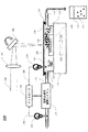
図2Aは、本発明の例示的実施形態に係る貴金属のバルクターゲットからPMNCを製造するためのPLAL方法のためのレーザベースのシステムの概略図である。図示のように、PLALシステム200は、レーザビーム202、レンズ204、ガイド機構206、ターゲット208、ターゲットホルダ210、懸濁液体212、容器214、撹拌バー216、発生されたPMNP218、光学窓220、Oリングシール222、運動ステージ224、入口226、出口228、電気伝導率調整システム230、電気伝導率監視デバイス232、電気伝導率監視デバイス234、コントローラ236、及び容器270への収集及び格納に先立つ液体の領域としてコロイド状懸濁液250を含む。
FIG. 2A is a schematic diagram of a laser-based system for a PLAL method for manufacturing PMNC from a noble metal bulk target according to an exemplary embodiment of the present invention. As shown, the
レーザビーム202は、パルス化レーザ源(図示せず)によって送出されることができ、レンズ204によって集光され且つガイド機構206によって案内されてターゲット208に照射する。他の例示的実施形態では、レンズ204は、ガイド機構206の後に配置されてもよい。レーザビーム202を発生するためのパルス化レーザ源は、100kHz乃至51MHzの調整可能パルス繰り返し数を有する1045ナノメートル(nm)で動作する市販の超高速ファイバレーザであってもよい。例えば、IMRA America Inc.から入手可能なD−1000IMRA超高速ファイバレーザは、レーザパルス源としてシステム200において利用されることができる。D−1000超高速ファイバレーザは、100kHzの繰り返し数でパルス当り10マイクロジュール(μJ)までのパルスエネルギー及び700フェムト秒(fs)より短いパルス幅を有するレーザパルスを生成できる。例として、レーザビーム202は、二次元レーザ走査システム、例えば、Fθレンズであってもよい焦点レンズ204を備えるX−Yガルバノメータスキャナ206でターゲットに案内されることができる。この例では、レーザ走査装置は、ポストオブジェクティブ操作システムとして構成される。他の適切な操作装置及びビーム/ターゲット位置決め機構は、走査速度、位置決め精度、及び他の変数に基づいて設計上の選択で利用されることができる。
市販の貴金属バルクターゲットとして受け取られることができるターゲット208は、ターゲットホルダ210に取り付けられることができる。ターゲット208は、平坦な表面を有する対象のバルク貴金属であり得る。ターゲット208とターゲットホルダ210は、数ミリメートル、好ましくは、2cm未満だけ、容器214中の懸濁液体212の表面よりも下に沈められる。撹拌バー216は、発生されたPMNP218がレーザ照射エリアに残ることを防止するのを助ける懸濁液体212の流れを発生することができる。懸濁液体212の流れは、また、レーザ焦点量(laser focal volume)を冷却する。
A
図2Aの例では、容器214は、光学窓220によって覆われる。Oリングシール222は、懸濁液体212が漏れるのを防止するために光学窓220と容器214との間に配置される。容器214は、容器214と懸濁液体212の指示されるような並進運動を生成する運動ステージ224に固定される。容器214は、入口226と出口228を有し、懸濁液体212は容器214を通って入口226から出口228に流れ、それによって、発生されたPMNP218が運び出されて容器214から外へ容器270に収集される。種々の実施では、懸濁液体212の流れは、ターゲット208の除去された材料と光学窓220との間のギャップを充填するのに十分に速くされるべきであり、それによって、レーザアブレーション中に発生されたガスの泡が光学窓220に留まることを回避する。光学窓220は、典型的にはガラス窓である。
In the example of FIG. 2A, the
懸濁液体212は、水、エタノール、アセトン、又は電解質を含む他の有機液体を含むことができ、PMNCを発生するための分散媒として働く。
The
電気伝導率調整システム230は、入口226近くの容器214の上流の位置に配置され、コントローラ236によって制御される。電気伝導率監視デバイス232は、電気伝導率調整システム230の前に懸濁液体212の上流側電気伝導率を監視するために使用される。電気伝導率監視デバイス234は、PMNP218を発生した後に容器214内の懸濁液体212の電気伝導率を監視するために使用される。コントローラ236は、電気伝導率監視デバイス232と234から夫々フィードバックデータ238と240を受け取り、電気伝導率調整システム230を制御し、それによって、要求された電気伝導率は、PLALによってPMNP218を発生する丁度前に懸濁液体212において安定化される。フィードバックデータ238と240は、コントローラ236と電気伝導率調整システム230と共に使用されて電気伝導率を監視且つ調整してそれをPMNPの望ましい粒度に依存する望ましい範囲内に維持できる。
The
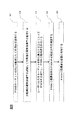
図3は、本発明の例示的実施形態に係る図2Aに示されるPLAL方法によるナノ粒子の発生から準備されたPMNCの格納までのプロセスを示す流れ図である。図示のように、プロセス300は、PMNCを発生するためのPLALを含み、このPLALは、液体中の電解質の電気伝導率を監視可能物理的パラメータとして使用して発生されたPMNPの粒度を正確に制御する。PLALによって発生されたPMNCは、PMNPを発生する前又はその発生中に電解液の電気伝導率を監視し且つ調整するプロセスを含む。PLALは、部分的に分散媒の電気コンダクタンスに基づいてPMNPの粒度を正確に制御する方法を提供できる。当業者によって理解されているように、溶液の電気抵抗率は、電気伝導率の逆数であり、従って、他の実施形態では、電解液又は分散媒の電気抵抗がデバイス223及び224の代わりに抵抗メータを使用して監視されてPLALによる発生された粒子サイズを制御するために望ましいパラメータ内に保たれる。本明細書及び特許請求の範囲において、電気伝導率が監視され且つ調整されるパラメータであるが、電気抵抗率は、望ましい電気伝導率値の逆数への変換の後に、電気伝導率に代えられることができる。
FIG. 3 is a flowchart illustrating a process from generation of nanoparticles to storage of prepared PMNC by the PLAL method illustrated in FIG. 2A according to an exemplary embodiment of the present invention. As shown, the
図示のように、ステップ302において、貴金属のターゲット208は、アブレーションターゲットのために、受け取られるか或いは提供される。一例示的実施形態では、ターゲット208は、容器214の頂部に除去可能光学窓220を有する容器214内に位置されるバルク金ターゲットを含む。ターゲット208は、懸濁液体212の表面より下、数ミリメートルから好ましくは1センチメートル未満の距離沈められる。ステップ302では、PMNPが中に分散されるべき媒体のような液体212も提供される。懸濁液体212は、レーザビーム202の波長に対して透過性があり且つ分布されるべきナノ粒子に対する分散媒として働く任意の液体でよく、且つナノ粒子は、分散媒全体を通して略均一に分布されることができる。懸濁液体212は、水、メタノール、エタノール、アセトン、又は電解質を含む他の有機液体を含むことができる。一実施形態では、懸濁液体212は、中に溶解された電解質を有する脱イオン化又は希釈水であり、そこでは、懸濁液体212の電気伝導率は、発生されたPMNP218に対して必要なサイズに従って、20μS/cmよりも小さい値、又は1μS/cmから10μS/cmまでの値、又は1.5μS/cmから8μS/cmまでの値に調整される。このように、PLALは、コロイド状金懸濁液が形成されるように、懸濁液体212中に現場でコロイド状金粒子(AuNC)を発生することができる。次に、形成された金ナノ粒子(AuNP)は、懸濁液体212内に安定的に懸濁され、従って、分散剤、安定化剤、界面活性剤又は他の材料は、コロイド状金懸濁液を安定状態に維持するために必要はない。このように、生の金ナノ粒子を含む独自のコロイド状金懸濁液が発生される。ここで、懸濁液体212中のイオン濃度は、懸濁液体212における電解質の量及び電解質の希釈又は濃縮のファクタ(倍数)に従って事前に推定されることができる。
As shown, at
ステップ304では、PMNP218を発生する前又はその最中の懸濁液体212の電気伝導率は、電気伝導率監視デバイス232,234によって監視される。懸濁液体212の電気伝導率は、その電気伝導率の調整がPMNP218の所定の粒度のために必要である場合、電気伝導率調整システム230によって調整されることができる。
In
上述のように、水中の全イオン濃度は、製造環境や格納のための容器材料への露出や大気への露出のような外部要因によって容易に変化する。容器との接触に続いて、水は、事前に推定されたイオン量に追加のイオンを含むことができ、それは、PLALを使用して高度に希釈された電解液における発生されたPMNP218に対する大きな衝撃を有することができる。実際に、水や電解液が何らかの外部接触を回避することは困難である。しかしながら、高度に希釈された電解液における全イオン濃度の不確実性の問題は、高度に希釈された電解液の電気伝導率を測定することによって、好ましくは、レーザビーム202をターゲット208に照射する前に高度に希釈された電解液の電気伝導率を測定することによって、本発明の少なくとも一実施形態で解決される。電気伝導率監視デバイス232,234は、高度に希釈された電解液の電気伝導率を測定するために種々の実施形態で使用される。例えば、電気伝導率監視デバイス232は、高度に希釈された電解液が容器214に入る前に高度に希釈された電解液の電気伝導率を測定するために入口226に配置される。電気伝導率監視デバイス234は、高度に希釈された電解液の電気伝導率を測定するために、PMNPが発生されない入口226に近接して容器214内に配置される。電気伝導率監視デバイス232,234は、市販の電気伝導率メータ、例えば、市販の水電気伝導率メータであってもよい。幾つかの実施形態では、約1μS/cmと5μS/cmとの間の電気伝導率における最小の検出可能変化は、市販の電気伝導率メータが電気伝導率監視デバイス232,234のために使用されることが必要である。上で論じたように、抵抗率は、電気伝導率の逆数であり、電気伝導率の1μS/cmから5μS/cmの範囲は、電気伝導率監視デバイス232,234のために抵抗率で1MΩcmから0.2MΩcmまでの範囲に変換される。抵抗率と電気伝導率との間の変換関係は、MΩcmにおける抵抗率=1/(μS/cmにおける電気伝導率)である。以降、これらの等価パラメータは、電気伝導率(μS/cm)に統合される。幾つかの実施形態では、電気伝導率測定に対する解は、約1μS/cm以上である。
As described above, the total ion concentration in water is easily changed by external factors such as the manufacturing environment, exposure to container materials for storage, and exposure to the atmosphere. Following contact with the vessel, the water can contain additional ions in the pre-estimated ion content, which is a significant impact on the generated
実験では、水又は電解液に外部から導入されたイオンの影響は、イオン濃度が30μM未満の範囲にある場合、最早無視できないことを示した。このように、発生されたAuNPの粒径は、イオン濃度が30μM未満の範囲にある場合、変化する。 Experiments have shown that the influence of ions introduced externally into water or electrolyte is no longer negligible when the ion concentration is in the range of less than 30 μM. Thus, the particle size of the generated AuNP changes when the ion concentration is in the range of less than 30 μM.
一般的に、電解液の電気伝導率は、固体が塩化ナトリウム(NaCl)であると仮定すると、水中の全溶解固体(TDS)に変換される。この変換を介して、1μS/cmの電気伝導率は、モル濃度で約10μMである、水のNaCl/kgの約0.6mgに対応する。その変換を考慮して、30μMのイオン濃度(その濃度未満では発生されたAuNPの粒度がそのイオン濃度に強く依存する)は、約3μS/cmの電気伝導率に対応する。特に、10μM以下のイオン濃度は、C.Rehbockらによれば、約15nmより大きなAuNPを製造するために必要である。 In general, the electrical conductivity of the electrolyte is converted to total dissolved solid (TDS) in water, assuming the solid is sodium chloride (NaCl). Through this conversion, an electrical conductivity of 1 μS / cm corresponds to about 0.6 mg of NaCl / kg of water, which is about 10 μM in molar concentration. Considering the conversion, an ion concentration of 30 μM (the particle size of AuNP generated depends strongly on the ion concentration below that concentration) corresponds to an electrical conductivity of about 3 μS / cm. In particular, an ion concentration of 10 μM or less is C.I. According to Rehbook et al., It is necessary to produce AuNPs larger than about 15 nm.
上で計算したように、NaClの10μMの導入は、約1μS/cmの電気伝導率の増加を引き起こす。それに比例して、NaClの1μMの導入は、電気伝導率の0.1μS/cmの増加を与えるに過ぎない。25℃の極度に浄化された水の電気伝導率は、0.055μS/cm程度に低いことが理論的に予測されている。しかしながら、実際に、格納され且つ室温で大気中において平衡化された脱イオン化水の典型的な電気伝導率は、0.5μS/cmと1.5μS/cmとの間の範囲にあることが認識されている。その結果、例えば、高度に希釈された電解液を格納容器からアブレーション容器214へ単純に転送すること且つ引き続くコロイド状懸濁液の格納は、分散媒中の初期のイオンの量を変化し得る。図4は、本発明の例示的実施形態に係る四つの異なる市販の容器に室温で格納された、電解質を含む脱イオン化水中の電気伝導率の時間の漸進的変化の例である。これらの容器は、三つの異なる透明なホウケイ酸ガラス瓶A、B、とC、及び一つの透明なポリカーボネート瓶Dである。脱イオン化水の初期の電気伝導率は、最初に取り出された時には、約1μS/cmである。図4に示されるように、脱イオン化水の電気伝導率は、それが格納される時間経過で増加する。特に、ガラス瓶では、最初の1週間における電気伝導率の増加は、1.3μS/cm以上である。その増加のレートは、最初の一週間後に減少されるが、電気伝導率は、なお、200日後に13μS/cmまで増加し続ける。そのデータは、プラスチック瓶内での格納は、時間経過にわたって電気伝導率の増加が最も遅く且つ最も小さくなることを示した。このように、好ましくは、発生されたPMNCと接触している、図2Aに示される容器244の材料は、ポリカーボネート、ポリエチレン、ポリエチレンテレフタレート、ポリエチレンテレフタレート共重合体、又はポリスチレンのようなポリマー又はプラスチックである。そのような容器材料を使用することは、分散媒とPMNCの電気伝導率を更に安定化することになる。
As calculated above, the introduction of 10 μM NaCl causes an increase in electrical conductivity of about 1 μS / cm. Proportionally, the introduction of 1 μM NaCl only gives a 0.1 μS / cm increase in electrical conductivity. It is theoretically predicted that the electrical conductivity of extremely purified water at 25 ° C. is as low as 0.055 μS / cm. However, in practice, the typical electrical conductivity of deionized water stored and equilibrated in the atmosphere at room temperature is recognized to be in the range between 0.5 μS / cm and 1.5 μS / cm. Has been. As a result, for example, a simple transfer of highly diluted electrolyte from the containment vessel to the
電気伝導率調整ステップ304は、現場で又は現場外(実験施設内)で実行されることができる。電気伝導率を制御することに関して、現場外のケースでは、懸濁液体212の外部イオン源への更なる露出が最小化された時にナノ粒子を発生するステップに先行して、直ちにその制御を実行することが望ましい。現場でのケースでは、一例示的実施形態では、図2Aに示されるPLALシステム200は、電気伝導率監視デバイス234を備えることができる。
The electrical
電気伝導率調整に関して、現場外のケースでは、電気伝導率調整ステップ304は、懸濁液体212の外部イオン源への更なる露出が最小化された時にナノ粒子を発生する次のステップに先行して、直ちに実行されることが好ましい。懸濁液体212の電気伝導率を増加するためには、KCl及びNaOHのような上記に列挙された電解質の溶液が、懸濁液体212に追加されることができる。懸濁液体212の電気伝導率を減少するためには、電気伝導率が2乃至3μS/cm以下である微量の電解質を含み得る脱イオン化又は希釈水が、懸濁液体212に追加されることができる。現場でのケースでは、一例示的実施形態では、図2Aに示されるレーザベースのシステム200は、上流の位置に、コントローラ236によって制御される電気伝導率調整システム230を有することができる。他の電気伝導率監視デバイス232は、電気伝導率調整システム230の前に、懸濁液体212の上流側電気伝導率を監視するために使用されることができる。電気伝導率監視デバイス232と234からのフィードバックデータ238と240を受け取ると、コントローラ236は、電気伝導率調整システム230を制御して、必要な電気伝導率がPLALによるPMNPの発生が起こる前に、懸濁液体212中において安定化される。
With regard to electrical conductivity adjustment, in the off-site case, electrical
少なくとも一つの実施では、システムは、電気伝導率調整の自動制御のために構成されることができる。第1の液体からの流れ制御は、電気伝導率を増加するように制御されることができ、第2の液体からは、電気伝導率を減少するように制御されることができる。コントローラ236は、電気伝導率を監視し較正情報に基づいて、電気伝導率を調整するためのプログラムを含むコンピュータ(図示せず)に動作上接続されることができる。幾つかの実施では、半自動又はコンピュータ支援制御が実施されることができる。
In at least one implementation, the system can be configured for automatic control of electrical conductivity adjustment. Flow control from the first liquid can be controlled to increase electrical conductivity and from the second liquid can be controlled to decrease electrical conductivity. The
ステップ306では、金ナノ粒子(AuNP)は、レーザビーム202をターゲット208に照射することによって発生される。図2Aに示されるように且つ上で論じられたように、レーザビーム202は、パルス化レーザ源(図示せず)によって送出され、レンズ204によって集光され且つガイド機構206によってターゲット208に案内される。ターゲットホルダ210に取り付けられたターゲット208は、平坦な表面を有する金のような貴金属のバルク材である。ターゲット208とターゲットホルダ210は、容器214中の懸濁液体212の表面より下、数ミリメートル、好ましくは2cm未満だけ沈めされる。撹拌バー216の移動によって発生された懸濁液体212の流れは、発生されたPMNP218がレーザ照射エリアに留まることを防止するのを助ける。懸濁液体212の流れは、レーザ焦点容積を冷却もする。液体層の厚みは、レーザビーム202の無視できる線形並びに非線形吸収によって決定される。このように、パルス化レーザ源の波長は、中赤外光から近赤外光範囲(例えば、約2000nmから780nmまで)、可視光範囲(例えば、700nmから400nmまで)、又は紫外光範囲(例えば、395nmから266nmまで)までであり得る。レーザビーム202は、10ナノジュール(nJ)から2ミリジュール(mJ)まで、又は50nJから300ミクロンジュール(μJ)まで、又は0.1から100μJまでのパルスエネルギーを提供できる。レーザビーム202は、10フェムト秒(fs)から100ナノ秒(ns)までの、又は100fsから10nsまでの、又は100fsから10ピコ秒(ps)までの持続時間を有するパルスを提供できる。
In
極端に短いパルス持続時間、例えば、100fsよりも短い持続時間は、望ましくない熱の影響を減少するが、パルス持続時間がfsの数十分の一に近づく場合、又は液体層が無視できない厚みを有する場合、液体(例えば、懸濁液体212)中の屈折率の波長分散に起因するパルスの時間的広がりが顕著になる。このような分散は、一つの技術又は複数の技術の組合せを使用して、補償されることができる。分散補償のための追加の光学的コンポーネントは、パルスの分散を補償するために光路中に挿入されることができる。分散補償のための光学的コンポーネントは、本発明を制限するわけではないが、一対の光学回折格子及び一対の容量ブラッグ格子を含む。反対の符号の分散を有する材料の挿入は、パルスの分散を補償することができる。光学導波路は、発明を制限するわけではないが、光ファイバ、フォトニック結晶ファイバ、フォトニックバンドギャップファイバ、非線形光ファイバを含み、ファイバブラッグ格子は、パルス持続時間の影響を補償できる。 Extremely short pulse durations, for example durations shorter than 100 fs, reduce undesirable thermal effects, but if the pulse duration approaches tens of fs or the liquid layer has a non-negligible thickness. If it has, the temporal spread of the pulse due to the wavelength dispersion of the refractive index in the liquid (for example, the suspension body 212) becomes remarkable. Such dispersion can be compensated using a single technique or a combination of techniques. Additional optical components for dispersion compensation can be inserted in the optical path to compensate for pulse dispersion. Optical components for dispersion compensation include, but are not limited to, a pair of optical diffraction gratings and a pair of capacitive Bragg gratings. The insertion of materials with opposite sign dispersion can compensate for pulse dispersion. Optical waveguides include, but are not limited to, optical fibers, photonic crystal fibers, photonic bandgap fibers, nonlinear optical fibers, and fiber Bragg gratings can compensate for the effects of pulse duration.
種々の例示的実施形態では、レーザビーム202は、1kHzから100MHzまでの、又は10kHzから1MHzまでの、又は100kHzから1MHzまでの、又は100kHzから10MHzまでのパルス繰り返し数を提供できる。ガイド機構206は、ターゲット208の表面へのレーザビーム202の高速走査又は他の移動のために構成された振動ミラーであり得る。振動ミラーの振動周波数は、1mrad以上の角度振幅を有する10Hz以上であることが好ましく、その表面への走査速度は、0.01m/s以上である。振動ミラーは、圧電駆動ミラー、ガルバノメータミラー、又はビーム移動のための他の適切な装置であり得る。二つ以上のミラーは、上で論じられたように、対物レンズの画像面での二次元移動を達成するために使用されることができる。好ましくは、画像面とターゲット208のターゲット表面は、全体的に平行であり、より好ましくは、レーザビーム202のターゲット208への入射角は、画像平面におけるスポットの位置から独立した一定角度である。他のレンズや他の複数のレンズは、光路に沿ってレーザビーム202の焦点の位置を調整するために実施されることもできる。
In various exemplary embodiments, the
幾つかの実施では、切断、プレス、機械加工及び形成後処理のようなモールディングステップ又は成形ステップは、ターゲット208の表面を平坦にするためにターゲット208のバルク貴金属に対して適用されることができる。平坦な表面は、研磨されることができる。
In some implementations, molding or shaping steps such as cutting, pressing, machining and post-formation processing can be applied to the bulk noble metal of the
ターゲットホルダ210は、ガラスのような光学的に耐久性があり化学的に不活性な材料で作られることができるが、それは、ターゲット208が所定位置に安定して保持される限り必要ない。
The
懸濁液体212は、中に溶解された電解質を有する脱イオン化又は希釈された水であってよく、懸濁液体212の電気伝導率は、発生されたPMNP218に必要なサイズに従って、ある特定の値、例えば、25μS/cm以下、好ましくは、1μS/cmから10μS/cmまで、より好ましくは、1.5μS/cmから8μS/cmまでに調整されることができる。
The
溶解された電解質は、以下の群から少なくとも一つの元素で形成された陰イオン及び陽イオンを含む無機又は有機塩であることができる。
Na及びKのようなアルカリ金属(例えば、周期表の第1族の元素);
Mg及びCaのようなアルカリ土類金属(例えば、周期表の第2族の元素);
N及びPのようなプニクトゲン(例えば、周期表の第15族の元素);
O及びSのようなカルコゲン(例えば、周期表の第16族の元素);
Cl、Br及びIのようなハロゲン(例えば、周期表の第17族の元素);及び
カルボン酸(COO−)のような有機酸基。
The dissolved electrolyte can be an inorganic or organic salt containing an anion and a cation formed with at least one element from the following group.
Alkali metals such as Na and K (for example, elements of
Alkaline earth metals such as Mg and Ca (eg, elements of
Pnictogens such as N and P (eg, elements of
Chalcogens such as O and S (eg elements of group 16 of the periodic table);
Halogens such as Cl, Br and I (for example, elements of group 17 of the periodic table); and organic acid groups such as carboxylic acids (COO-).
レーザアブレーションシステム200は、液体循環システム(図示せず)を含む。懸濁液体212の流れは、入口226と出口228を介して液体循環システムによって容器214に導入される。懸濁液体212は、好ましくは、1ml/s以上の速度で、より好ましくは、10ml/s以上の速度で流れる。ここで、懸濁液体212の流れ、レーザビーム202のターゲット208への移動、又はそれらの両方は、レーザ照射のエリアでの熱の蓄積を制御するために使用されることができる。
光学窓220は、ターゲット208とガラスウインドウ220との間のギャップが流れる懸濁液体212で充填されるように、小さな粒子発生のために容器214の頂部に配置される。液体の流れは、発生されたPMNP218を懸濁液体212内に均一に分配することができる。容器214の頂部に光学窓220が無い場合、流れる懸濁液体212の上表面は、流れる間中変動する可能性があり、アブレーションターゲット208の上方で懸濁液体212の厚みに変動が引き起こされる可能性がある。これは、レーザビーム202の光路を変化する可能性があり、発生されたPMNP218のより広い粒度分布を引き起こす可能性がある。従って、本発明の望ましい実施形態では、流れる懸濁液体212の上方の光学窓220は、アブレーションターゲット208の上方に懸濁液体212の一定深さを保つために導入される。更に、循環システム無しでは、例えば、図2Aに示されるようにレーザビーム202に対して垂直な、運動ステージ224に対する横方向振動移動AA−BBは、懸濁液体212をターゲット208のアブレーションスポットを横切るように局所的に流させることもある。
The
運動ステージ224は、好ましくは、数Hzの振動周波数、例えば、約0.001から100Hzの範囲内の振動周波数と、数ミリメートルの振幅を有する。シェイカー(図示せず)は、液体循環を発生するために使用されてもよく、シェーカーの円運動は、懸濁液体212の円運動も引き起こす。光学窓220は、運動ステージ224又はシェーカーを使用するために必要ないかもしれない。しかしながら、運動ステージ224又はシェーカーの使用は、ターゲット208の上方の液層の厚みに不均一を導入する可能性があり、発生されたPMNP218のより広い粒度分布を引き起こす可能性がある。
The motion stage 224 preferably has a vibration frequency of a few Hz, for example a vibration frequency in the range of about 0.001 to 100 Hz, and an amplitude of a few millimeters. A shaker (not shown) may be used to generate the liquid circulation, and the circular motion of the shaker also causes the circular motion of the
代替の実施形態では、ターゲット208は、懸濁液体212中に完全に沈められなくてもよい。ターゲット208の一部が懸濁液体212と接触状態にある限り、PLALによるレーザアブレーションは、ターゲット208と懸濁液体212との界面で発生し得る。
In an alternative embodiment, the
発生されたPMNP218が存在する懸濁液体212の一部は、液体212の領域250として示される、コロイド状懸濁液の形態で収集され、ステップ306の結果として容器270に収集され格納される。コロイド状懸濁液250の収集は、ステップ306の後又はそのステップ中に行われる。循環システムのために、コロイド状懸濁液250は、懸濁液体212が出口228から入口226に移動する間の任意の適切な位置で取り出されることができる。
The portion of
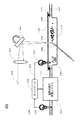
PLALの他の実施形態では、ターゲット材料は、図2Bにおいて概略的に示されるように外部から液体中に送られるワイヤ形状の貴金属であってもよい。レーザベースのシステム201は、レーザビーム202B、レンズ204B、ガイド機構206B、アブレーションのためのワイヤ形状ターゲット208B、懸濁液体212B、容器214B、撹拌バー216B、発生されたPMNP218B、光学窓220B、Оリングシール222B、入口226B、出口228B、電気伝導率調整システム230B、電気伝導率監視デバイス232B,234B、及びコントローラ236Bを含む。図2Aの実施の形態と図2Bの実施の形態との違いは、図2Aにおいて、ターゲット208が、ワイヤ形状ターゲット208Bによって置き換えられていることである。ワイヤ形状ターゲット208Bは、ワイヤ形状ターゲット208Bの先頭がレーザビーム202Bの焦点量内に維持されるように容器214Bに流れ込むことができる。このように、レーザベースのシステム201は、運動ステージを含まない。一例示的実施形態では、ワイヤ形状ターゲット208Bは、一片の金ワイヤである。
In other embodiments of PLAL, the target material may be a wire-shaped noble metal that is fed into the liquid from the outside as shown schematically in FIG. 2B. The laser-based
図5Aは、本発明の例示的実施形態に係るPLAL方法によって発生されたAuNPの粒度分布の漸進的変化である。電気伝導率のレベルは、1.0μS/cmから75μS/cmの範囲であり、電気伝導率が粒度分布に劇的に影響を及ぼすことが理解される。例えば、ペンシルベニア州のCPS Instruments, Inc.から入手されるCPS Disk Centriguge DC24000UHRを使用する解析超遠心分離の方法がAuNPのサイズ分布を測定するために適用される。粒度分布は、AuNPの重み分布に基づいて得られた。重み分布は、粒子の数とその粒度での一つの粒子の質量の積の分布である。図5Aに示される正規化分布は、異なる電気伝導率の電解質懸濁液媒体で作られたAnNPの相対的個体群密度を示す。 FIG. 5A is a gradual change in the particle size distribution of AuNP generated by the PLAL method according to an exemplary embodiment of the present invention. It is understood that the level of electrical conductivity ranges from 1.0 μS / cm to 75 μS / cm, and that electrical conductivity dramatically affects the particle size distribution. For example, CPS Instruments, Inc. of Pennsylvania. An analytical ultracentrifugation method using CPS Disk Centrigage DC24000UHR obtained from is applied to measure the size distribution of AuNP. The particle size distribution was obtained based on the weight distribution of AuNP. The weight distribution is the product distribution of the number of particles and the mass of one particle at that particle size. The normalized distribution shown in FIG. 5A shows the relative population density of AnNP made with electrolyte suspension media of different electrical conductivity.
図5Bは、異なる電気伝導率電解質懸濁液媒体においてPLAL方法によって発生されたAuNPの粒度分布における粒度ピークのプロットである。電解質懸濁媒体の電気伝導率が示されるように適切に安定化されると、35nm以上の粒度、好適には、AuNPの約10nmから約60nmまでの範囲の粒度を製造できる。C.Rehockらは、約32nmの最も大きな粒度は、電気伝導率が、恐らく少なくとも0.5μS/cmよりも低い時に1μM NaCl溶液で作られることを報告している。しかしながら、本発明は、35nmAuNPが、図5Bに示されるように、1.6μS/cmの電気伝導率を有する電解質溶液で作られることができることを示している。その結果として、電解質溶液中のイオンの過剰量の存在は、提案されており、それは、NaClの既知の量から推定される物よりも電解質溶液のかなりより高い電気伝導率を引き起こしている。これは、本発明で開示されるように、全イオン濃度が電気伝導率を介して適切に推定される場合に、イオン濃度と粒度に関して、Rehbockらの教示と正反対である。 FIG. 5B is a plot of the particle size peak in the particle size distribution of AuNP generated by the PLAL method in different conductivity electrolyte suspension media. When properly stabilized, as indicated by the conductivity of the electrolyte suspending medium, particle sizes of 35 nm or more, preferably in the range of about 10 nm to about 60 nm of AuNP can be produced. C. Reock et al. Report that the largest particle size of about 32 nm is made with a 1 μM NaCl solution when the electrical conductivity is probably lower than at least 0.5 μS / cm. However, the present invention shows that 35 nm AuNP can be made with an electrolyte solution having an electrical conductivity of 1.6 μS / cm, as shown in FIG. 5B. As a result, the presence of an excess of ions in the electrolyte solution has been proposed, which causes a much higher electrical conductivity of the electrolyte solution than that deduced from the known amount of NaCl. This is the exact opposite of the teaching of Rehock et al. With respect to ion concentration and particle size when the total ion concentration is properly estimated via electrical conductivity, as disclosed in the present invention.
図5Cにおいて、粒度ピークは、均等目盛で懸濁液媒体の電気伝導率に対してプロットされている。図5Cは、望ましい粒度を生成するためにPLALに対する分散媒において電気伝導率を安定化することが如何に決定的に重要であるかを強調している。図5Cの斜線エリア550は、10nm以上のピーク粒度を有するAuNPを作製するために必要な領域である。電気伝導率依存性の勾配は、AuNPのターゲット粒度がより大きくなるに従って、増々急勾配になる。勾配の絶対値は、斜線エリア550において約0.83(nm)/(μS/cm)から約33(nm)/(μS/cm)に変化する。
In FIG. 5C, the particle size peaks are plotted against the electrical conductivity of the suspension medium on a uniform scale. FIG. 5C highlights how critically important it is to stabilize the electrical conductivity in the dispersion medium for PLAL to produce the desired particle size. The hatched
その結果は、電気伝導率を介する電解質溶液における全イオン濃度を測定し且つ維持することがPLALによって生成されるPMNPの粒度を確実にするために非常に重要なステップであることを確認する。 The result confirms that measuring and maintaining the total ion concentration in the electrolyte solution via electrical conductivity is a very important step to ensure the particle size of PMNP produced by PLAL.
ステップ308で、発生されたPMNP又はPMNCの粒度分布は精製される。電気伝導率安定化電解液におけるPLALは正確に制御された粒度ピークを有する粒度分布を生成するが、粒度分布は、なお、副ピーク又はショルダ構造を含みうる。望ましくない粒度を有するこれらの粒子を除去するために、例えば、遠心力場が適用される。より大きなサイズの粒子の除去のためには、例えば、上澄み部分が遠心力を受けたPMNCから取り出されることができる。より小さなサイズの粒子の除去のために、ペレット部分が遠心力を受けたPMNCから取り出されることができ、次に、そのペレット部分は、電解質溶液又は脱イオン化水を添加することによって、再分散されることができる。図5Dは、遠心分離方法によって精製された粒度分布に対するデータを示す。AuNPの元の分布は、短い点線でプロットされている。粒度の少なくとも二つの個体群があることが明瞭に認められる。約10nmの第1の鋭いピークがあり、約15nmから約75nmの範囲に広いショルダがある。実線は、60分にわたる500Gでの遠心分離の後に除去された上澄み液中の粒度分布を示す。このデータは、15nmから30nmの粒度の粒子の小さな尾部を有する5乃至15nmのより小さな粒度の粒子は上澄み液中に留まることを明確に示している。破線は、分散媒中への再懸濁後のペレット中の粒度分布を示している。粒子の大部分を有する7から12nmの範囲にある少数の粒子は、15から75nmの範囲内にあることを知ることができる。この例示の方法では、粒度分布は、遠心力を使用して、その分布を少なくとも二つの粒度分布の個体群に分離することによって精製されることができる。
At
ステップ310では、発生されたPMNCは、SERSのような用途で使用される前に適切な格納状態下で容器に格納される。本発明に係るPLALによって発生されたPMNCは、20μS/cm未満の、大部分は、1μS/cmから10μS/cmの範囲内の電気伝導率を有する。しかしながら、図4に示されるように、この電気伝導率は、PMNCが容器に格納される時に時間経過と共に増加を続ける。増加のレートは、容器の化学的性質によって部分的に決定される。
In
発生されたPMNCと接触している容器の材料は、好ましくは、ポリカーボネート、ポリエチレン、ポリエチレンテレフタレート、ポリエチレンテレフタレート共重合体、又はポリスチレンのようなポリマー又はプラスチックである。図4からの結果は、ホウケイ酸系ガラス、及び多分全てのガラス容器が格納容器のためには回避されるべきであることを提案している。電気伝導率が種々のガラス容器に対するプラスチック容器における少なくとも時間経過に従って変化した。 The container material in contact with the generated PMNC is preferably a polymer or plastic such as polycarbonate, polyethylene, polyethylene terephthalate, polyethylene terephthalate copolymer, or polystyrene. The results from FIG. 4 suggest that borosilicate glass and possibly all glass containers should be avoided for containment. The electrical conductivity changed at least over time in the plastic containers relative to the various glass containers.
溶解ガスは、コロイド状溶液の結果としての電気伝導率に影響を及ぼす可能性があり、従って、容器は、窒素ガス又はヘリウム、ネオン、アルゴン及びクリプトン雰囲気を含む希ガスのような不活性ガス化でパージされ且つシールされる。 The dissolved gas can affect the electrical conductivity as a result of the colloidal solution, and therefore the vessel is inert gasified such as nitrogen gas or noble gases including helium, neon, argon and krypton atmospheres. Purged and sealed.
格納温度に関して、PMNCは、冷蔵庫におけるように、40℃未満、好ましくは,25℃未満に維持されることができる。 With respect to storage temperature, the PMNC can be kept below 40 ° C., preferably below 25 ° C., as in a refrigerator.
格納環境に関して、太陽光への露出は、回避されなければならない。好ましくは、PMNCを有する容器は、暗い場所に維持されるか又は琥珀色の容器が使用されなければならない。 With respect to the storage environment, exposure to sunlight must be avoided. Preferably, the container with PMNC should be kept in a dark place or an amber container should be used.
発生後約4か月の間25μS/cmよりも低い電気伝導率を保つために、電気伝導率の増加のレートは、一週間当たり1.5μS/cm以下、好ましくは、一週間当り1μS/cm以下、最も好ましくは、一週間当たり0.5μS/cm以下であることが必要である。このように、コロイド状懸濁液の電気伝導率は、好ましくは、25μS/cm未満であり、約1μS/cmから22μS/cm、又は約1.5μS/cmから15μS/cmの範囲内にあり得る。電気伝導率の変化に関して、容器に格納されたコロイド状懸濁液の電気伝導率の増加は、好ましくは、一週間当たり1.5μS/cm未満、一週間当たり1μS/cm未満、或いは一週間当たり0.5μS/cm未満である。 In order to maintain an electrical conductivity lower than 25 μS / cm for about 4 months after the occurrence, the rate of increase in electrical conductivity is 1.5 μS / cm or less per week, preferably 1 μS / cm per week. In the following, it is most preferable that it is 0.5 μS / cm or less per week. Thus, the electrical conductivity of the colloidal suspension is preferably less than 25 μS / cm and is in the range of about 1 μS / cm to 22 μS / cm, or about 1.5 μS / cm to 15 μS / cm. obtain. With respect to changes in electrical conductivity, the increase in electrical conductivity of the colloidal suspension stored in the container is preferably less than 1.5 μS / cm per week, less than 1 μS / cm per week, or per week It is less than 0.5 μS / cm.
本発明の驚くべき有利な効果は、種々の実施形態で製造されたPMNPは、平均粒度を更に増加するために利用されることができ、それは、PMNCの電気伝導率が減少すると生じることである。粒度増加を制御する能力は、本発明を介して準備されたPMNCが認識されることができる性質のみならず、例えば、約15nm以上の大きさのPMNPの収率を増加するために利用されることができる有用な機能である。所与の幅の広い粒度分布から指定の粒度範囲を得るために、図5Dに示される遠心分離による粒度分布精製が適用されることができる。しかしながら、遠心分離方法は、原則として、通常PMNPの大きな損失を引き起こし且つ低収率となる、粒度フィルタ処理プロセスである。対照的に、脱イオン水又は高希釈電解質溶液での希釈による、又は幾つかの実施形態では、透析によるようなPMNC中における電気伝導率の減少は、粒度ピークをより大きなサイズの粒子にシフトし、それによって、100%の収率を達成できる。粒度増加が生じる電気伝導率の最小閾値は、20μS/cm以下、10μS/cm以下、又は5μS/cm以下であり得る。 A surprising and advantageous effect of the present invention is that PMNP produced in various embodiments can be utilized to further increase the average particle size, which occurs when the electrical conductivity of the PMNC decreases. . The ability to control the increase in particle size is utilized not only for the properties that PMNCs prepared via the present invention can be recognized, but for example, to increase the yield of PMNPs of the size of about 15 nm or more. It is a useful feature that can. To obtain a specified particle size range from a given broad particle size distribution, particle size distribution purification by centrifugation as shown in FIG. 5D can be applied. However, the centrifuge method is, as a rule, a particle size filtering process that usually causes a large loss of PMNP and results in a low yield. In contrast, a decrease in electrical conductivity in PMNC, such as by dilution with deionized water or highly diluted electrolyte solution, or in some embodiments, by dialysis, shifts the particle size peak to larger size particles. Thereby, a yield of 100% can be achieved. The minimum electrical conductivity threshold at which particle size increase occurs can be 20 μS / cm or less, 10 μS / cm or less, or 5 μS / cm or less.
図6は、PMNPの粒度分布に対するPMNC中の電気伝導率を低下する効果を示す。6.6μS/cmの初期の電気伝導率を有するAuNCは、PLAL方法で準備された。これらのAuNCは、約10nmのピーク粒度を有していた。粒子は、脱イオン化水で希釈されて電気伝導率を3.4μS/cmまで減少し、且つ粒度ピークが約11nmまでシフトアップされた。粒子は、更に2.4μS/cmの電気伝導率に希釈され、且つピークが12.5nm超えるまで上昇された。電気伝導率が減少すると、粒度のピークがより大きな平均粒度へシフトし、それは、特に、SERSのような以下で記述される種々の用途に対して有利である。電気伝導率に対する閾値の理想は、電気伝導率がこの閾値未満の時に、ナノ粒子の流動がより低い電気伝導率によって劇的に増加されることができることが、図5Cに示されるこのデータから知られることができる。正確なメカニズムを理解することは、個体群のサイズの変更を実行するために必要ではないが、本願の発明者等は、電気伝導率減少によって起動される粒度の増加が、遷移凝集状態を介する粒子の合体に起因することを仮定する。このことは、電気伝導率の増加直後に、集合が初期に起こるが、次にその集合が、安定し且つ単一の粒子のように挙動する粒子の合体になることを意味する。 FIG. 6 shows the effect of reducing the electrical conductivity in PMNC on the particle size distribution of PMNP. AuNC having an initial electrical conductivity of 6.6 μS / cm was prepared by the PLAL method. These AuNCs had a peak particle size of about 10 nm. The particles were diluted with deionized water to reduce the electrical conductivity to 3.4 μS / cm and the particle size peak was shifted up to about 11 nm. The particles were further diluted to an electrical conductivity of 2.4 μS / cm and raised to a peak exceeding 12.5 nm. As the electrical conductivity decreases, the particle size peak shifts to a larger average particle size, which is particularly advantageous for various applications described below, such as SERS. From the data shown in FIG. 5C, the threshold ideal for electrical conductivity is shown that the nanoparticle flow can be dramatically increased by lower electrical conductivity when the electrical conductivity is below this threshold. Can be done. While understanding the exact mechanism is not necessary to perform population size changes, the inventors of the present application believe that the increase in particle size triggered by the decrease in electrical conductivity is via a transition aggregation state Assume that it is due to particle coalescence. This means that immediately after the increase in electrical conductivity, aggregation occurs early, but then the aggregation becomes a coalescence of particles that are stable and behave like a single particle.
本願の発明者等の実験から決定された本発明の他の有利な効果は、電気伝導率の良好に制御され且つ抑制された増加のおかげでコロイドの長期間の安定性が増加することである。準備された時の初期の電解質濃度が非常に小さい場合でも、コロイド系は、関連するイオンが容器の表面からコロイド状溶液に出続けるので、格納中時間経過と共に、不安定になる。図4で論証されているように、外部から導入された電解質の量の時間の漸進的変化は、電気伝導率を監視することによって推定されることができ、且つ事前に決定されることができる。 Another advantageous effect of the present invention, determined from the inventors' experiments, is that the long-term stability of the colloid is increased thanks to a well-controlled and suppressed increase in electrical conductivity. . Even when the initial electrolyte concentration when prepared is very small, the colloidal system becomes unstable over time as the associated ions continue to emerge from the surface of the container into the colloidal solution. As demonstrated in FIG. 4, the time evolution of the amount of electrolyte introduced from the outside can be estimated by monitoring the electrical conductivity and can be determined in advance. .
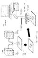
本発明に従って準備されたPMNCの分光用途は、本発明を制限するわけではないが、表面増強共振ラマン分光法(SERRS)、表面増強ハイパーラマン分光法(SEHRS)又は表面増強コヒーレントアンチストークラマン分光法(SECARS)を含む。これらの分光用途に対して、PMNCの物理形態は、図7Aに示されるようにコロイド状懸濁液であってもよいし、又は図7Bに示されるように、懸濁液体の蒸発によってPMNC溶液から作られたPMNPのキャストフィルムであってもよい。 The spectral applications of PMNC prepared in accordance with the present invention do not limit the present invention, but include surface enhanced resonance Raman spectroscopy (SERRS), surface enhanced hyper Raman spectroscopy (SEHRS) or surface enhanced coherent anti-stocraman spectroscopy. (SECARS). For these spectroscopic applications, the physical form of PMNC may be a colloidal suspension as shown in FIG. 7A, or a PMNC solution by evaporation of the suspension as shown in FIG. 7B. PMNP cast film made from
図7Aにおいて、PMNC711は、対象の分析物712を含む溶液と混合される。混合された溶液は、少なくとも一波長を有する励起光713がラマン散乱を発生するために照射される石英キュベットのような光学的に透明な容器715内に配置される。散乱光714は、レンズ719によって集められ、対象のラマン信号750が存在する散乱光におけるスペクトルの一部又は全てを測定する分光計720に適切な案内光学系を介して送達される。PMNCへの分析物結合は、信号の強調を引き起こす。案内光学系は、励起光からの信号を減少するために一つ以上の光学フィルタを有する。励起光713の光源は、連続波又はパルス化レーザ、又はハロゲンランプのようなランプであり得る。
In FIG. 7A,
図7Bは、分析物が混合されたPMNCのキャストフィルムが使用されるラマン分光器のための他の装置を示す。二つの溶液が図7Aに示されるのと同じ方法で混合され、その混合液がスライドガラスのような基板716上に滴下されて分析物を有するPMNPを含有するキャストフィルム718を形成する。基板の材料は、基板からのラマン信号が分析物に対する測定において干渉しないように選択されることができる。キャストフィルムの基板に対する分光法を実行するために、例えば、対物レンズ718を有する顕微鏡ラマンシステムが利用されることができる。
FIG. 7B shows another apparatus for a Raman spectrometer in which a cast film of PMNC mixed with analyte is used. The two solutions are mixed in the same way as shown in FIG. 7A and the mixture is dropped onto a
他の有益な用途は、表面増強ラマン方法の上記ファミリを含む光学顕微鏡画像形成及び顕微鏡ラマン画像形成のための物のような造影剤としてPMNPを使用することである。 Another beneficial application is the use of PMNP as a contrast agent such as an optical microscope imaging and object for microscope Raman imaging, including the above family of surface enhanced Raman methods.
図8は、顕微鏡画像形成のために造影剤としてのPMNPの例示の用途を示す。例えば、PMNC803中のPMNP805は、細胞815が成長される細胞培養環境に追加される。細胞815は、2時間から2乃至3日の間PMNP805で培養され、次に、恐らく、光学顕微鏡下で見られる、細胞培養環境として使用される容器又は皿で培養される。PMNP805は、細胞の内側又はその周りに局所化されることができるか、又は細胞核17のような細胞の指定の部分に局所化されることができ、細胞の形状が可視化される。PMNP805の表面は、PMNP805が対象の細胞の一部分又は部分に具体的に結合するように、ターゲットとされたリガンドのような分子で機能化されることができる。
FIG. 8 shows an exemplary use of PMNP as a contrast agent for microscopic imaging. For example,
上記のPMNPの用途として、PMNPの局所化された表面プラズモンリソースから生じる光学特性が利用されることができる。 As an application of the above-mentioned PMNP, optical properties resulting from the localized surface plasmon resource of PMNP can be used.
PMNCは、x線を介する放射線医学画像形成のような画像形成用途にも使用されることができ、大きな横断面を有するPMNPの利点が利用される。PMNPが大きければ大きい程、それらの横断面が大きく、それは、放射線透過写真におけるコントラストも向上する。 PMNC can also be used in imaging applications such as radiological imaging via x-rays, taking advantage of PMNP having a large cross section. The larger the PMNP, the larger their cross-section, which improves the contrast in radiographic photographs.
図9は、放射線医学画像形成のための造影剤(コントラスト剤)としてのPMNPの例示の用途を示す。PMNP901は、体内に腫瘍950を有する被験者920に注入される。PMNP901の表面は、一つ以上のリガンドで機能化されてPMNP901が送達されるように設計される腫瘍を標的とする。PMNP901が腫瘍950の周りに局所化されるのに十分に長い培養時間の後に、被験者920の放射線透過写真が腫瘍950の位置を可視化するためにX線910を使用して取られる。PMNPは、X線画像におけるコントラストを強調する。
FIG. 9 illustrates an exemplary use of PMNP as a contrast agent (contrast agent) for radiological imaging. PMNP901 is injected into a subject 920 having a tumor 950 in the body. The surface of PMNP901 targets tumors that are functionalized with one or more ligands and designed to deliver PMNP901. After a culture time that is long enough for
市販の簡易妊娠テストキットにおいて使用されているように側方流動免疫クロマトグラフィー分析法のような免疫クロマトグラフィー方法は、「A gold nanoparticle−based immunochromatographic assay:The influence of nanoparticulate size」Analyst,2012,137,1174−1181においてS.LouらによるAuNPで報告されているように大きな粒度は感度を向上するために、PMNPに対する他の一つの将来有望な用途である。ここで記述されるようにコロイド状懸濁液から得られる貴金属ナノ粒子は、化学的に作られた貴金属ナノ粒子に対する代替として免疫クロマトグラフィーのためのシステムの少なくとも一つの実施形態において利用されることができる。 Immunochromatographic methods such as lateral flow immunochromatographic analysis as used in commercial simple pregnancy test kits are described in “A gold nanoparticle-based immunoassay assay: The intensity of nanoparticulate 37, A1. , 1174-1118. Larger granularity, as reported by Lou et al. In AuNP, is another promising application for PMNP to improve sensitivity. Noble metal nanoparticles obtained from a colloidal suspension as described herein are utilized in at least one embodiment of a system for immunochromatography as an alternative to chemically produced noble metal nanoparticles. Can do.
PMNPの光学的性質を利用するために、PMNPの正確なサイズ制御は、光学特性がPMNPの粒度で敏感に変化するので、種々の好適な実施形態において実施される。ラマン分光計では、テスト中の材料との放射線相互作用のために大きな横断面を提供することが望ましい。このように、より大きなナノ粒子、例えば、約15から75nmの最大直径を有するナノ粒子の相対的個体群密度(粒子/容積)を増加することは有利である。しかしながら、図5Cに斜線エリア550で示されるように、要求された粒度が、極端に急峻な勾配のために、より大きくなると、PLALが粒度を制御することが増々困難になる。
In order to take advantage of the optical properties of PMNP, precise size control of PMNP is implemented in various preferred embodiments since the optical properties change sensitively with the particle size of PMNP. In a Raman spectrometer, it is desirable to provide a large cross section for radiation interaction with the material under test. Thus, it is advantageous to increase the relative population density (particle / volume) of larger nanoparticles, eg, nanoparticles having a maximum diameter of about 15 to 75 nm. However, as indicated by the hatched
PMNPの粒度は、PLALを実行することに先立って、液体に導入された既知の量の電解質によって調整されることができる。しかしながら、高希釈電解質溶液が10nm以上、特に20nm以上の大きさのPMNPを製造することが必要な場合、汚染物のような予期せずに導入された微量の電解質は、粒度へのその影響に関して最早無視できない。本発明の実施形態は、予期せずに導入された電解質の量の不確実さに起因する結果としての粒度の不確実さを減少すると共に、ラマン用途での収率も増加する。換言すれば、本発明に係る電気伝導度によって表される、分散媒中の全イオン濃度を測定する方法を知ることなく、全イオン濃度への粒度の徹底的な依存性は、予測されなかった。 The particle size of PMNP can be adjusted by a known amount of electrolyte introduced into the liquid prior to performing PLAL. However, if a highly diluted electrolyte solution is required to produce PMNPs with a size of 10 nm or more, especially 20 nm or more, unexpectedly introduced trace amounts of electrolytes, such as contaminants, may be related to their effect on particle size. It can no longer be ignored. Embodiments of the present invention reduce the resulting particle size uncertainty due to uncertainties in the amount of electrolyte introduced unexpectedly, and also increase the yield in Raman applications. In other words, without knowing how to measure the total ion concentration in the dispersion medium, represented by the electrical conductivity according to the present invention, a thorough dependence of the particle size on the total ion concentration was not expected. .
少なくとも一つの実施形態において、本発明は、貴金属ナノ粒子のコロイド状懸濁液を作製する方法であって、その方法は、a)所定の電気伝導率範囲内にある電気伝導率を有する液体の分散媒と接触状態にある貴金属を備えるターゲット材料を提供するステップを備え、前記ターゲット材料と前記分散媒がアブレーション容器と接触状態にあり、b)レーザパルスを前記アブレーション容器内の前記ターゲット材料に送出することによって複数の貴金属ナノ粒子を発生するステップと、c)前記複数の貴金属ナノ粒子を発生する前又は発生中に、前記分散媒の前記電気伝導率を、所定の粒度範囲を有する前記貴金属ナノ粒子を生じさせる前記所定の電気伝導率範囲に維持するために前記分散媒の前記電気伝導率を監視しつつ選択的に調整するステップと、d)前記貴金属ナノ粒子のコロイド状懸濁液を形成するステップとを備える。 In at least one embodiment, the present invention is a method of making a colloidal suspension of noble metal nanoparticles comprising: a) a liquid having an electrical conductivity within a predetermined electrical conductivity range. Providing a target material comprising a noble metal in contact with a dispersion medium, wherein the target material and the dispersion medium are in contact with an ablation container, and b) delivering a laser pulse to the target material in the ablation container. A step of generating a plurality of noble metal nanoparticles, and c) before or during the generation of the plurality of noble metal nanoparticles, the electrical conductivity of the dispersion medium having the predetermined particle size range. Selectively adjust the electrical conductivity of the dispersion medium while monitoring the electrical conductivity range of the dispersion medium to maintain the predetermined electrical conductivity range that produces particles. Comprising the steps, and forming a colloidal suspension of d) the noble metal nanoparticles.
少なくとも一つの実施形態では、本方法は、貴金属のナノ粒子における、夫々が異なる維持された電気伝導率を有する分散媒の中に発生される複数の個体群を発生するステップと、各個体群を収集し、各電気伝導率で正規化されたピークのナノ粒子の粒度よりなる一連のデータポイントを決定するために各個体群における前記ナノ粒子の粒度と個体群密度分布とを測定するステップと、前記電気伝導率に対する前記ピークのナノ粒子の粒度をグラフ化して、前記データポイントを結合するラインをプロットするステップとを更に備え、前記ラインは、前記所定の粒度範囲を得る前記所定の電気伝導率範囲を選択可能な(nmでの粒度)/(μS/cm)の勾配を有している。 In at least one embodiment, the method includes generating a plurality of populations of noble metal nanoparticles generated in dispersion media each having a different maintained electrical conductivity; and Measuring the particle size and population density distribution of the nanoparticles in each population to determine a series of data points comprising the particle size of the peak nanoparticles collected and normalized for each conductivity; Graphing the particle size of the peak nanoparticles against the electrical conductivity and plotting a line connecting the data points, the line having the predetermined electrical conductivity to obtain the predetermined particle size range. It has a gradient of selectable range (particle size in nm) / (μS / cm).
少なくとも一つの実施形態では、本方法は、約0.83(nm)/(μS/cm)以上の大きさの前記勾配の絶対値を有する前記ラインの一部から前記所定の電気伝導率範囲を選択する更なるステップを備える。 In at least one embodiment, the method may include removing the predetermined conductivity range from a portion of the line having an absolute value of the gradient greater than or equal to about 0.83 (nm) / (μS / cm). With further steps to select.
少なくとも一つの実施形態では、本方法は、約33(nm)/(μS/cm)以上の大きさの前記勾配の絶対値を有する前記ラインの一部から前記所定の電気伝導率範囲を選択する更なるステップを備える。 In at least one embodiment, the method selects the predetermined electrical conductivity range from a portion of the line having an absolute value of the gradient greater than or equal to about 33 (nm) / (μS / cm). With further steps.
少なくとも一つの実施形態では、本方法は、遠心力を前記コロイド状懸濁液に付与して前記ナノ粒子を上澄み部分とペレット部分とに分離して、前記所定の粒度範囲を狭めることを許容する更なるステップを備える。 In at least one embodiment, the method allows centrifugal force to be applied to the colloidal suspension to separate the nanoparticles into a supernatant portion and a pellet portion, thereby narrowing the predetermined particle size range. With further steps.
少なくとも一つの実施形態では、前記電気伝導率を監視する前記ステップは、一つ以上の電気伝導率監視デバイスによって実行される。 In at least one embodiment, the step of monitoring the electrical conductivity is performed by one or more electrical conductivity monitoring devices.
少なくとも一つの実施形態では、前記分散媒の前記電気伝導率を監視しつつ選択的に調整する前記ステップは、前記アブレーション容器の入口近くの前記アブレーション容器の上流位置に配置された電気伝導率調整システムによって実行される。 In at least one embodiment, the step of selectively adjusting the electrical conductivity of the dispersion medium while monitoring is an electrical conductivity adjustment system disposed at an upstream position of the ablation container near an inlet of the ablation container. Executed by.
少なくとも一つの実施形態では、前記電気伝導率調整システムは、前記分散媒中に配置された一つ以上の電気伝導率監視デバイスを備え、前記一つ以上の電気伝導率監視デバイスの内の第1の電気伝導率監視デバイスは、前記アブレーション容器の前記入口に配置され、前記一つ以上の電気伝導率監視デバイスの内の第2の電気伝導率監視デバイスは、貴金属ナノ粒子が発生されない前記入口近くの前記アブレーション容器に配置される。 In at least one embodiment, the electrical conductivity adjustment system comprises one or more electrical conductivity monitoring devices disposed in the dispersion medium, and the first of the one or more electrical conductivity monitoring devices. An electrical conductivity monitoring device is disposed at the inlet of the ablation vessel, and a second one of the one or more electrical conductivity monitoring devices is near the inlet where noble metal nanoparticles are not generated. Of the ablation container.
少なくとも一つの実施形態では、前記電気伝導率調整システムは、前記所定の電気伝導率が前記貴金属ナノ粒子の発生前又は発生中に安定化されるように、前記第1と前記第2の電気伝導率監視デバイスからのフィードバックデータを受け取るコントローラによって制御される。 In at least one embodiment, the electrical conductivity adjustment system includes the first and second electrical conductivity so that the predetermined electrical conductivity is stabilized before or during the generation of the noble metal nanoparticles. Controlled by a controller that receives feedback data from the rate monitoring device.
少なくとも一つの実施形態では、貴金属ナノ粒子を発生する前記ステップは、パルス化レーザアブレーションビームで前記ターゲット材料を照射すること及び前記貴金属の複数のナノ粒子を形成することを含み、前記ナノ粒子は、約1nmから1000nmまでの範囲内の所定の粒度範囲を有する。 In at least one embodiment, the step of generating noble metal nanoparticles comprises irradiating the target material with a pulsed laser ablation beam and forming a plurality of nanoparticles of the noble metal, the nanoparticles comprising: It has a predetermined particle size range within the range of about 1 nm to 1000 nm.
少なくとも一つの実施形態では、前記ナノ粒子は、約5から150nmまでの範囲内の所定の粒度範囲を有する。 In at least one embodiment, the nanoparticles have a predetermined size range within the range of about 5 to 150 nm.
少なくとも一つの実施形態では、前記ナノ粒子は、約10から100nmまでの範囲内の所定の粒度範囲を有する。 In at least one embodiment, the nanoparticles have a predetermined size range within the range of about 10 to 100 nm.
少なくとも一つの実施形態では、前記分散媒の前記電気伝導率は、25μS/cm以下の範囲内の所定の電気伝導率範囲に調整される。 In at least one embodiment, the electrical conductivity of the dispersion medium is adjusted to a predetermined electrical conductivity range within a range of 25 μS / cm or less.
少なくとも一つの実施形態では、前記分散媒の前記電気伝導率は、1μS/cmから10μS/cmまでの範囲内の所定の電気伝導率範囲に調整される。 In at least one embodiment, the electrical conductivity of the dispersion medium is adjusted to a predetermined electrical conductivity range within a range of 1 μS / cm to 10 μS / cm.
少なくとも一つの実施形態では、前記分散媒の前記電気伝導率は、1.5μS/cmから8μS/cmまでの範囲内の所定の電気伝導率範囲に調整される。 In at least one embodiment, the electrical conductivity of the dispersion medium is adjusted to a predetermined electrical conductivity range within a range of 1.5 μS / cm to 8 μS / cm.
少なくとも一つの実施形態では、前記レーザパルスは、1kHzから100MKzまでの範囲内の繰り返し数を有する。 In at least one embodiment, the laser pulse has a repetition rate in the range of 1 kHz to 100 MKz.
少なくとも一つの実施形態では、前記レーザパルスは、10nJから2mJまでの範囲内のパルスエネルギーを有する。 In at least one embodiment, the laser pulse has a pulse energy in the range of 10 nJ to 2 mJ.
少なくとも一つの実施形態では、前記レーザパルスは、紫外線光、可視光、又は近赤外光波長に波長の中心を有する。 In at least one embodiment, the laser pulse has a wavelength center at an ultraviolet light, visible light, or near infrared wavelength.
少なくとも一つの実施形態では、前記レーザパルスは、100fsから10nsまでの範囲内のパルス持続時間を有する。 In at least one embodiment, the laser pulse has a pulse duration in the range of 100 fs to 10 ns.
少なくとも一つの実施形態では、前記レーザパルスは、100fsから10psまでの範囲内のパルス持続時間を有する。 In at least one embodiment, the laser pulse has a pulse duration in the range of 100 fs to 10 ps.
少なくとも一つの実施形態では、前記分散媒は、前記アブレーション容器の入口から出口まで流れる。 In at least one embodiment, the dispersion medium flows from the inlet to the outlet of the ablation vessel.
少なくとも一つの実施形態では、前記コロイド状懸濁液は、1μS/cmより大きく且つ22μS/cmよりも小さい電気伝導率を有する。 In at least one embodiment, the colloidal suspension has an electrical conductivity greater than 1 μS / cm and less than 22 μS / cm.
少なくとも一つの実施形態では、前記コロイド状懸濁液は、1.5μS/cmより大きく且つ15μS/cmよりも小さい電気伝導率を有する。 In at least one embodiment, the colloidal suspension has an electrical conductivity greater than 1.5 μS / cm and less than 15 μS / cm.
少なくとも一つの実施形態では、前記コロイド状懸濁液は、格納容器に配置され、前記容器内の前記コロイド状懸濁液の電気伝導率の増加は、一週間当り1.5μS/cm未満である。 In at least one embodiment, the colloidal suspension is placed in a containment vessel, and the increase in electrical conductivity of the colloidal suspension in the vessel is less than 1.5 μS / cm per week. .
少なくとも一つの実施形態では、前記コロイド状懸濁液は、格納容器に配置され、前記容器内の前記コロイド状懸濁液の電気伝導率の増加は、一週間当り1μS/cm未満である。 In at least one embodiment, the colloidal suspension is placed in a containment vessel, and the increase in electrical conductivity of the colloidal suspension in the vessel is less than 1 μS / cm per week.
少なくとも一つの実施形態では、前記コロイド状懸濁液は、格納容器に配置され、前記容器内の前記コロイド状懸濁液の電気伝導率の増加は、一週間当り0.5μS/cm未満である。 In at least one embodiment, the colloidal suspension is placed in a containment vessel and the increase in electrical conductivity of the colloidal suspension in the vessel is less than 0.5 μS / cm per week. .
少なくとも一つの実施形態では、前記貴金属は、金、銀、銅、白金、パラジウム、ロジウム、ルテニウム、イリジウム、オスミウム、又は前記貴金属の内の少なくとも一つを含む合金から成る群から選択される。 In at least one embodiment, the noble metal is selected from the group consisting of gold, silver, copper, platinum, palladium, rhodium, ruthenium, iridium, osmium, or an alloy comprising at least one of the noble metals.
少なくとも一つの実施形態では、前記貴金属は、第11族元素である。
In at least one embodiment, the noble metal is a
少なくとも一つの実施形態では、前記分散媒は、少なくとも一つの陰イオン又は陽イオンを含む有機塩又は無機塩である電解質を備える。 In at least one embodiment, the dispersion medium comprises an electrolyte that is an organic or inorganic salt containing at least one anion or cation.
少なくとも一つの実施形態では、前記少なくとも一つの陰イオン又は陽イオンは、周期表における第1族元素、周期表における第2族元素、周期表における第15族元素、周期表における第16族元素、周期表のおける第17族元素、及び有機酸基からなる群から選択された少なくとも一つの元素を含む。
In at least one embodiment, the at least one anion or cation comprises a
少なくとも一つの実施形態では、前記コロイド状懸濁液中の前記貴金属ナノ粒子の濃度は、0.01nMよりも高い。 In at least one embodiment, the concentration of the noble metal nanoparticles in the colloidal suspension is greater than 0.01 nM.
少なくとも一つの実施形態では、本発明は、電解質を含む液体中に0.01nMを越える濃度を有する複数の貴金属ナノ粒子を備えるコロイド状懸濁液であって、前記コロイド状懸濁液は、閾値未満に前記コロイド状懸濁液の電気伝導率が減少すると、前記貴金属ナノ粒子の前記平均粒度の増加を示す。 In at least one embodiment, the present invention is a colloidal suspension comprising a plurality of noble metal nanoparticles having a concentration of greater than 0.01 nM in a liquid comprising an electrolyte, the colloidal suspension comprising a threshold value A decrease in the electrical conductivity of the colloidal suspension below indicates an increase in the average particle size of the noble metal nanoparticles.
少なくとも一つの実施形態では、前記貴金属ナノ粒子の平均粒度が増加するために必要な前記電気伝導率の前記閾値は、20μS/cm以下である。 In at least one embodiment, the threshold value of the electrical conductivity required for increasing the average particle size of the noble metal nanoparticles is 20 μS / cm or less.
少なくとも一つの実施形態では、前記貴金属ナノ粒子の平均粒度が増加するために必要な前記電気伝導率の前記閾値は、10μS/cm以下である。 In at least one embodiment, the threshold value of the electrical conductivity required for increasing the average particle size of the noble metal nanoparticles is 10 μS / cm or less.
少なくとも一つの実施形態では、前記貴金属ナノ粒子の平均粒度が増加するために必要な前記電気伝導率の前記閾値は、5μS/cm以下である。 In at least one embodiment, the threshold value of the electrical conductivity required for increasing the average particle size of the noble metal nanoparticles is 5 μS / cm or less.
少なくとも一つの実施形態では、前記貴金属ナノ粒子の平均粒度は、約10nm以上である。 In at least one embodiment, the noble metal nanoparticles have an average particle size of about 10 nm or more.
少なくとも一つの実施形態では、前記貴金属ナノ粒子の平均粒度は、約15nm以上である。 In at least one embodiment, the noble metal nanoparticles have an average particle size of about 15 nm or more.
少なくとも一つの実施形態では、前記貴金属ナノ粒子の平均粒度は、約20nm以上である。 In at least one embodiment, the noble metal nanoparticles have an average particle size of about 20 nm or more.
少なくとも一つの実施形態では、分光法システムは、電解質を含む液体中に0.01nMを越える濃度を有する貴金属ナノ粒子のコロイド状懸濁液を備え、前記コロイド状懸濁液は、閾値未満に前記コロイド状懸濁液の電気伝導率が減少すると、前記貴金属ナノ粒子の前記平均粒度の増加を示す。 In at least one embodiment, the spectroscopic system comprises a colloidal suspension of noble metal nanoparticles having a concentration greater than 0.01 nM in a liquid comprising an electrolyte, the colloidal suspension being less than a threshold value. A decrease in the electrical conductivity of the colloidal suspension indicates an increase in the average particle size of the noble metal nanoparticles.
少なくとも一つの実施形態では、前記分光法システムは、ラマン分光法のために構成される。 In at least one embodiment, the spectroscopy system is configured for Raman spectroscopy.
少なくとも一つの実施形態では、前記ラマン分光法は、表面増強ラマン分光法(SERS)、表面増強共振ラマン分光法(SERRS)、表面増強ハイパーラマン分光法(SEHRS)又は表面増強コヒーレントアンチストークラマン分光法(SECARS)を備える。 In at least one embodiment, the Raman spectroscopy is surface enhanced Raman spectroscopy (SERS), surface enhanced resonance Raman spectroscopy (SERRS), surface enhanced hyper Raman spectroscopy (SEHRS) or surface enhanced coherent anti-stocraman spectroscopy. (SECARS).
少なくとも一つの実施形態では、本発明は、基板上に配置されたキャストフィルムを備える分光法システムであって、前記キャストフィルムは、電解質を含む液体中に0.01nMより超える濃度を有する複数の貴金属ナノ粒子を備えるコロイド状懸濁液と電解質との混合物から得られる貴金属の粒子を備え、前記コロイド状懸濁液は、閾値未満に前記コロイド状懸濁液の電気伝導率が減少すると、前記貴金属ナノ粒子の前記平均粒度の増加を示す。 In at least one embodiment, the present invention is a spectroscopy system comprising a cast film disposed on a substrate, wherein the cast film has a plurality of noble metals having a concentration of greater than 0.01 nM in a liquid containing an electrolyte. Comprising particles of a noble metal obtained from a mixture of a colloidal suspension comprising nanoparticles and an electrolyte, wherein the colloidal suspension reduces the electrical conductivity of the colloidal suspension below a threshold, and the noble metal The increase in the average particle size of the nanoparticles is shown.
少なくとも一つの実施形態では、前記分光法システムは、ラマン分光法のために構成される。 In at least one embodiment, the spectroscopy system is configured for Raman spectroscopy.
少なくとも一つの実施形態では、前記ラマン分光法は、表面増強ラマン分光法(SERS)、表面増強共振ラマン分光法(SERRS)、表面増強ハイパーラマン分光法(SEHRS)又は表面増強コヒーレントアンチストークラマン分光法(SECARS)を備える。 In at least one embodiment, the Raman spectroscopy is surface enhanced Raman spectroscopy (SERS), surface enhanced resonance Raman spectroscopy (SERRS), surface enhanced hyper Raman spectroscopy (SEHRS) or surface enhanced coherent anti-stocraman spectroscopy. (SECARS).
少なくとも一つの実施形態では、本発明は、電解質を含む液体中に0.01nMより超える濃度を有する複数の貴金属ナノ粒子を備えるコロイド状懸濁液から得られる貴金属ナノ粒子を備える免疫クロマトグラフィー分析法のための装置であって、前記コロイド状懸濁液は、閾値未満に前記コロイド状懸濁液の電気伝導率が減少すると、前記貴金属ナノ粒子の平均粒度の増加を示す。 In at least one embodiment, the present invention provides an immunochromatographic assay comprising noble metal nanoparticles obtained from a colloidal suspension comprising a plurality of noble metal nanoparticles having a concentration of greater than 0.01 nM in a liquid comprising an electrolyte. The colloidal suspension exhibits an increase in the average particle size of the noble metal nanoparticles when the electrical conductivity of the colloidal suspension decreases below a threshold.
少なくとも一つの実施形態では、本発明は、電解質を含む液体中に0.01nMより超える濃度を有する複数の貴金属ナノ粒子を備えるコロイド状懸濁液から得られる貴金属ナノ粒子を備える画像形成剤であって、前記コロイド状懸濁液は、閾値未満に前記コロイド状懸濁液の電気伝導率が減少すると、前記貴金属ナノ粒子の平均粒度の増加を示す。 In at least one embodiment, the present invention is an imaging agent comprising noble metal nanoparticles obtained from a colloidal suspension comprising a plurality of noble metal nanoparticles having a concentration of greater than 0.01 nM in a liquid comprising an electrolyte. Thus, the colloidal suspension exhibits an increase in the average particle size of the noble metal nanoparticles when the electrical conductivity of the colloidal suspension decreases below a threshold value.
少なくとも一つの実施形態では、前記画像形成剤は、光画像形成のためである。 In at least one embodiment, the imaging agent is for photoimaging.
少なくとも一つの実施形態では、前記画像形成剤は、放射線医学画像形成のためである。 In at least one embodiment, the imaging agent is for radiological imaging.
少なくとも一つの実施形態では、前記画像形成剤は、生物学画像形成である。 In at least one embodiment, the imaging agent is biological imaging.
少なくとも一つの実施形態では、前記コロイド状懸濁液は、前記コロイド状懸濁液の前記電気伝導率が20μS/cm以下の量だけ初期の値から減少すると、前記コロイド状懸濁液中の前記貴金属ナノ粒子の平均粒度の増加を示す。 In at least one embodiment, the colloidal suspension may be in the colloidal suspension when the electrical conductivity of the colloidal suspension decreases from an initial value by an amount of 20 μS / cm or less. 3 shows an increase in the average particle size of noble metal nanoparticles.
少なくとも一つの実施形態では、前記コロイド状懸濁液は、前記コロイド状懸濁液の前記電気伝導率が10μS/cm以下の量だけ初期の値から減少すると、前記コロイド状懸濁液中の前記貴金属ナノ粒子の平均粒度の増加を示す。 In at least one embodiment, the colloidal suspension may be in the colloidal suspension when the electrical conductivity of the colloidal suspension is reduced from an initial value by an amount of 10 μS / cm or less. 3 shows an increase in the average particle size of noble metal nanoparticles.
少なくとも一つの実施形態では、前記コロイド状懸濁液は、前記コロイド状懸濁液の前記電気伝導率が5μS/cm以下の量だけ初期の値から減少すると、前記コロイド状懸濁液中の前記貴金属ナノ粒子の平均粒度の増加を示す。 In at least one embodiment, the colloidal suspension may be in the colloidal suspension when the electrical conductivity of the colloidal suspension decreases from an initial value by an amount of 5 μS / cm or less. 3 shows an increase in the average particle size of noble metal nanoparticles.
少なくとも一つの実施形態では、本発明は、コロイド状懸濁液中の貴金属のナノ粒子の個体群を前記貴金属ナノ粒子の平均粒度が減少するように変化する方法であって、前記方法は、a)初期の電気伝導率を有するコロイド状懸濁液を受け取るステップと、b)前記初期値から前記コロイド状懸濁液の前記電気伝導率を減少させるステップとを備える。 In at least one embodiment, the present invention is a method of changing a population of noble metal nanoparticles in a colloidal suspension such that the average particle size of the noble metal nanoparticles is reduced, the method comprising: a A) receiving a colloidal suspension having an initial electrical conductivity; and b) reducing the electrical conductivity of the colloidal suspension from the initial value.
少なくとも一つの実施形態では、前記方法のステップb)は、前記コロイド状懸濁液の遠心分離浄化又は透析を備える。 In at least one embodiment, step b) of the method comprises centrifugal clarification or dialysis of the colloidal suspension.
少なくとも一つの実施形態では、ステップb)における前記電気伝導率の前記減少は、20μS/cm以下である。 In at least one embodiment, the decrease in the electrical conductivity in step b) is not more than 20 μS / cm.
少なくとも一つの実施形態では、ステップb)における前記電気伝導率の前記減少は、10μS/cm以下である。 In at least one embodiment, the decrease in the electrical conductivity in step b) is 10 μS / cm or less.
少なくとも一つの実施形態では、ステップb)における前記電気伝導率の前記減少は、5μS/cm以下である。 In at least one embodiment, the decrease in the electrical conductivity in step b) is 5 μS / cm or less.
本発明を要約する目的で、本発明の幾つかの態様、利点及び新規な特徴がここで記述される。しかしながら、そのような利点の全てが、特定の実施形態に従って必ずしも達成されるわけではないことが理解されるべきである。このように、本発明は、ここで教示又は提案されるように、他の利点を必ずしも達成するのではなく一つ以上の利点を達成する方法で具体化又は実施されることができる。 For purposes of summarizing the invention, certain aspects, advantages and novel features of the invention will now be described. However, it should be understood that not all such advantages are necessarily achieved in accordance with a particular embodiment. Thus, the present invention may be embodied or practiced in a manner that achieves one or more advantages, rather than necessarily achieving other advantages, as taught or suggested herein.
このように、ここでは幾つかの実施形態のみが具体的に記述されたが、本発明の精神及び範囲から逸脱することなく、多くの変更がこれらの実施形態に対してなされることができることは明白である。装置は、相互に排他的ではないことが理解されるべきである。要素は、望ましい設計目的を成就するために適切な方法において実施形態同士で組み合わされてもよい。更に、頭字語は、明細書と特許請求の範囲の読み易さを向上するために単に使用される。これらの頭字語は、使用された用語の一般性を減ずることを意図してはおらず、それらは、ここで記述された実施形態に特許請求の範囲を制限するものと解釈されるべきではないことに留意すべきである。 Thus, although only some embodiments have been specifically described herein, many changes can be made to these embodiments without departing from the spirit and scope of the present invention. It is obvious. It should be understood that the devices are not mutually exclusive. Elements may be combined between embodiments in a suitable manner to achieve the desired design objectives. Moreover, acronyms are merely used to improve the readability of the specification and claims. These acronyms are not intended to diminish the generality of the terms used, and they should not be construed to limit the scope of the claims to the embodiments described herein. Should be noted.
Claims (11)
前記コロイド状懸濁液は、前記電解質が希釈されて20μS/cm以下に前記コロイド状懸濁液の電気伝導率が減少すると、前記貴金属ナノ粒子の平均粒度の増加を示すコロイド状懸濁液。 A colloidal suspension comprising a plurality of noble metal nanoparticles having a concentration of greater than 0.01 nmol / L in a liquid comprising an electrolyte,
The colloidal suspension shows an increase in the average particle size of the noble metal nanoparticles when the electrolyte is diluted and the electrical conductivity of the colloidal suspension decreases to 20 μS / cm or less .
a)液体の分散媒と接触状態にある貴金属を備えるターゲット材料を提供するステップを備え、前記ターゲット材料と前記分散媒がアブレーション容器と接触状態にあり、a) providing a target material comprising a noble metal in contact with a liquid dispersion medium, wherein the target material and the dispersion medium are in contact with an ablation vessel;
b)レーザパルスを前記アブレーション容器内の前記ターゲット材料に送出することによって複数の貴金属ナノ粒子を発生するステップと、b) generating a plurality of noble metal nanoparticles by delivering a laser pulse to the target material in the ablation vessel;
c)前記複数の貴金属ナノ粒子を発生する前又は発生中に、前記分散媒の電気伝導率を15μS/cm以下に維持するように前記分散媒の前記電気伝導率を監視しつつ調整するステップと、c) adjusting while monitoring the electrical conductivity of the dispersion medium so as to maintain the electrical conductivity of the dispersion medium at 15 μS / cm or less before or during the generation of the plurality of noble metal nanoparticles; ,
d)前記貴金属ナノ粒子のコロイド状懸濁液を形成するステップと、を備える方法。d) forming a colloidal suspension of the noble metal nanoparticles.
Applications Claiming Priority (3)
| Application Number | Priority Date | Filing Date | Title |
|---|---|---|---|
| US201361764649P | 2013-04-29 | 2013-04-29 | |
| US61/764,649 | 2013-04-29 | ||
| PCT/US2014/016348 WO2014178935A1 (en) | 2013-04-29 | 2014-02-14 | Size controlled suspension of precious metal nanoparticles |
Publications (3)
| Publication Number | Publication Date |
|---|---|
| JP2016530395A JP2016530395A (en) | 2016-09-29 |
| JP2016530395A5 JP2016530395A5 (en) | 2017-12-07 |
| JP6327337B2 true JP6327337B2 (en) | 2018-05-23 |
Family
ID=51843849
Family Applications (1)
| Application Number | Title | Priority Date | Filing Date |
|---|---|---|---|
| JP2016510668A Expired - Fee Related JP6327337B2 (en) | 2013-04-29 | 2014-02-14 | Suspension with controlled particle size of noble metal nanoparticles |
Country Status (2)
| Country | Link |
|---|---|
| JP (1) | JP6327337B2 (en) |
| WO (1) | WO2014178935A1 (en) |
Families Citing this family (4)
| Publication number | Priority date | Publication date | Assignee | Title |
|---|---|---|---|---|
| JP6912553B2 (en) * | 2016-09-07 | 2021-08-04 | 株式会社スギノマシン | Method for producing metal nanocolloids by laser ablation |
| AT519146B1 (en) * | 2016-10-05 | 2020-03-15 | Univ Wien Tech | Device for analyzing a solid sample material |
| CN110227889A (en) * | 2019-05-08 | 2019-09-13 | 上海维宏智能技术有限公司 | Have clean gas monitoring function laser head assembly and corresponding monitoring method |
| EP4221929A1 (en) * | 2020-10-01 | 2023-08-09 | University of South Africa | Method of producing a nanofluid using laser ablation, corresponding nanofluid and laser ablation system for manufacturing nanofluids |
Family Cites Families (8)
| Publication number | Priority date | Publication date | Assignee | Title |
|---|---|---|---|---|
| US4764271A (en) * | 1987-02-13 | 1988-08-16 | Acosta William A | Water treatment apparatus |
| CA2537199C (en) * | 2003-08-28 | 2011-11-29 | Tama-Tlo, Ltd. | Precious metal colloid, precious metal microparticle, composition, and process for producing the precious metal microparticle |
| US20060144765A1 (en) * | 2004-12-30 | 2006-07-06 | Timothy Skwiot | Conductivity measurement and monitoring system for a fluid treatment system |
| EP2045028A1 (en) * | 2007-09-26 | 2009-04-08 | Fujifilm Corporation | Metal nanoparticles, method for producing the same, aqueous dispersion, method for manufacturing printed wiring or electrode, and printed wiring board or device |
| US8246714B2 (en) * | 2009-01-30 | 2012-08-21 | Imra America, Inc. | Production of metal and metal-alloy nanoparticles with high repetition rate ultrafast pulsed laser ablation in liquids |
| JP5466226B2 (en) * | 2009-03-04 | 2014-04-09 | 有限会社マイテック | Surface-enhanced Raman scattering activity measurement substrate |
| JP2011202265A (en) * | 2010-03-26 | 2011-10-13 | Dowa Electronics Materials Co Ltd | Low temperature sinterable metal nanoparticle composition and electronic article formed using the composition |
| US8697129B2 (en) * | 2011-03-02 | 2014-04-15 | Imra America, Inc. | Stable colloidal gold nanoparticles with controllable surface modification and functionalization |
-
2014
- 2014-02-14 JP JP2016510668A patent/JP6327337B2/en not_active Expired - Fee Related
- 2014-02-14 WO PCT/US2014/016348 patent/WO2014178935A1/en active Application Filing
Also Published As
| Publication number | Publication date |
|---|---|
| JP2016530395A (en) | 2016-09-29 |
| WO2014178935A1 (en) | 2014-11-06 |
Similar Documents
| Publication | Publication Date | Title |
|---|---|---|
| US9999865B2 (en) | Method of reliable particle size control for preparing aqueous suspension of precious metal nanoparticles and the precious metal nanoparticle suspension prepared by the method thereof | |
| JP6773818B2 (en) | How to Prepare an Aqueous Suspension of Precious Metal Nanoparticles | |
| Kamarudheen et al. | Plasmon-driven synthesis of individual metal@ semiconductor core@ shell nanoparticles | |
| Arakelyan et al. | Reliable and well-controlled synthesis of noble metal nanoparticles by continuous wave laser ablation in different liquids for deposition of thin films with variable optical properties | |
| Yang et al. | Size and structure control of Si nanoparticles by laser ablation in different liquid media and further centrifugation classification | |
| Herbst et al. | Nucleation and growth kinetics of ZnO nanoparticles studied by in situ microfluidic SAXS/WAXS/UV–Vis experiments | |
| Hartland et al. | Softening of the symmetric breathing mode in gold particles by laser-induced heating | |
| Giammanco et al. | Experimental and theoretical analysis of photofragmentation of Au nanoparticles by picosecond laser radiation | |
| JP6327337B2 (en) | Suspension with controlled particle size of noble metal nanoparticles | |
| Lee et al. | Light-driven transformation processes of anisotropic silver nanoparticles | |
| Liu et al. | Quantifying the nucleation and growth kinetics of microwave nanochemistry enabled by in situ high-energy X-ray scattering | |
| Kotsifaki et al. | Plasmon enhanced optical tweezers with gold-coated black silicon | |
| Fong et al. | Influence of cationic surfactants on the formation and surface oxidation states of gold nanoparticles produced via laser ablation | |
| Sardari et al. | Real-time and tunable substrate for surface enhanced Raman spectroscopy by synthesis of copper oxide nanoparticles via electrolysis | |
| Barberio et al. | In situ study of nucleation and aggregation phases for nanoparticles grown by laser-driven methods | |
| Baimler et al. | Water decomposition occurring during laser breakdown of aqueous solutions containing individual gold, zirconium, molybdenum, iron or nickel nanoparticles | |
| de Goes et al. | Tuning of citrate-stabilized laser ablated silver nanoparticles for glyphosate detection | |
| Du et al. | Improved optical limiting performance of laser-ablation-generated metal nanoparticles due to silica-microsphere-induced local field enhancement | |
| Freeland et al. | Real-time monitoring and control for high-efficiency autonomous laser fabrication of silicon nanoparticle colloids | |
| Rahman et al. | Excess surface energy at the tips of gold nanospikes: from experiment to modeling | |
| Ma et al. | Measurement of two-photon absorption cross section of metal ions by a mass sedimentation approach | |
| Ali et al. | Preparation of silver nanoparticles by pulsed laser ablation in liquid medium | |
| Shimotsuma et al. | Photoconversion of copper flakes to nanowires with ultrashort pulse laser irradiation | |
| Abu-Hatab et al. | Multiplexed microfluidic surface-enhanced Raman spectroscopy | |
| Megat Abdul Hedei et al. | Spectral aging of gold and silver nanoparticles synthesized by laser ablation in liquids |
Legal Events
| Date | Code | Title | Description |
|---|---|---|---|
| A521 | Request for written amendment filed |
Free format text: JAPANESE INTERMEDIATE CODE: A523 Effective date: 20160927 |
|
| A621 | Written request for application examination |
Free format text: JAPANESE INTERMEDIATE CODE: A621 Effective date: 20160927 |
|
| A131 | Notification of reasons for refusal |
Free format text: JAPANESE INTERMEDIATE CODE: A131 Effective date: 20170829 |
|
| A524 | Written submission of copy of amendment under article 19 pct |
Free format text: JAPANESE INTERMEDIATE CODE: A524 Effective date: 20171027 |
|
| TRDD | Decision of grant or rejection written | ||
| A01 | Written decision to grant a patent or to grant a registration (utility model) |
Free format text: JAPANESE INTERMEDIATE CODE: A01 Effective date: 20180320 |
|
| A61 | First payment of annual fees (during grant procedure) |
Free format text: JAPANESE INTERMEDIATE CODE: A61 Effective date: 20180402 |
|
| R151 | Written notification of patent or utility model registration |
Ref document number: 6327337 Country of ref document: JP Free format text: JAPANESE INTERMEDIATE CODE: R151 |
|
| LAPS | Cancellation because of no payment of annual fees |