JP6325954B2 - Electric vacuum cleaner - Google Patents

Electric vacuum cleaner Download PDF

Info

Publication number
JP6325954B2
JP6325954B2 JP2014190555A JP2014190555A JP6325954B2 JP 6325954 B2 JP6325954 B2 JP 6325954B2 JP 2014190555 A JP2014190555 A JP 2014190555A JP 2014190555 A JP2014190555 A JP 2014190555A JP 6325954 B2 JP6325954 B2 JP 6325954B2
Authority
JP
Japan
Prior art keywords
handle
vacuum cleaner
connecting pipe
extending
cylindrical portion
Prior art date
Legal status (The legal status is an assumption and is not a legal conclusion. Google has not performed a legal analysis and makes no representation as to the accuracy of the status listed.)
Active
Application number
JP2014190555A
Other languages
Japanese (ja)
Other versions
JP2016059640A (en
Inventor
粛雄 釣田
粛雄 釣田
Current Assignee (The listed assignees may be inaccurate. Google has not performed a legal analysis and makes no representation or warranty as to the accuracy of the list.)
Iris Ohyama Inc
Original Assignee
Iris Ohyama Inc
Priority date (The priority date is an assumption and is not a legal conclusion. Google has not performed a legal analysis and makes no representation as to the accuracy of the date listed.)
Filing date
Publication date
Application filed by Iris Ohyama Inc filed Critical Iris Ohyama Inc
Priority to JP2014190555A priority Critical patent/JP6325954B2/en
Publication of JP2016059640A publication Critical patent/JP2016059640A/en
Application granted granted Critical
Publication of JP6325954B2 publication Critical patent/JP6325954B2/en
Active legal-status Critical Current
Anticipated expiration legal-status Critical

Links

Images

Description

本発明は、キャニスタ式の電気掃除機に関する。   The present invention relates to a canister-type vacuum cleaner.

一般的なキャニスタ式の電気掃除機は、掃除機本体と、掃除機本体の吸引口に一端が接続されるホースと、ホースの他端に接続された接続管と、接続管に接続された吸込口体とを備えている。この電気掃除機では、操作者の取手位置の高さを調整するために、接続管は、第1接続管と、当該第1接続管に対して挿抜自在に設けられた第2接続管とからなる。
また、例えば、特許文献1では、掃除機本体、ホース、接続管および吸込口体の他に、接続管に対して伸縮自在に設けられた取手を備えた電気掃除機が提案されている。この電気掃除機では、取手位置の高さ調整のために、接続管に対して取手が伸縮できるようになっている。
A typical canister-type vacuum cleaner has a vacuum cleaner main body, a hose connected at one end to the suction port of the vacuum cleaner main body, a connecting pipe connected to the other end of the hose, and a suction connected to the connecting pipe. It has a mouth. In this vacuum cleaner, in order to adjust the height of the handle position of the operator, the connection pipe is composed of a first connection pipe and a second connection pipe provided so as to be insertable / removable with respect to the first connection pipe. Become.
Further, for example, Patent Document 1 proposes an electric vacuum cleaner including a handle provided in a retractable manner with respect to the connection pipe, in addition to the vacuum cleaner body, the hose, the connection pipe, and the suction port body. In this vacuum cleaner, the handle can be expanded and contracted with respect to the connecting pipe in order to adjust the height of the handle position.

特開2003−219995号公報JP 2003-219995 A

しかしながら、上記の掃除機では安全性に劣るという課題がある。例えば、前者の電気掃除機では、第1接続管に対して第2接続を縮める際に、第1接続管と第2接続管との間に指を挟むおそれがある。後者の電気掃除機では、接続管に対して取手を縮める際に、接続管と取手との間に指を挟むおそれがある。
本発明は、安全性の高い電気掃除機を提供することを目的とする。
However, there exists a subject that it is inferior to safety | security with said vacuum cleaner. For example, in the former vacuum cleaner, when the second connection is contracted with respect to the first connection pipe, there is a possibility that a finger is pinched between the first connection pipe and the second connection pipe. In the latter vacuum cleaner, when the handle is shrunk with respect to the connection tube, there is a risk that a finger may be pinched between the connection tube and the handle.
An object of this invention is to provide a highly safe vacuum cleaner.

上記課題を解決するため、本発明の一実施形態に係る電気掃除機は、掃除機本体と、前記掃除機本体に下流側端が接続されるホースと、前記ホースの上流側端に下流側端が接続される接続管と、接続管の上流側端に接続される吸込口体と、前記接続管の管軸方向に沿って移動自在に設けられ、前記接続管からの延伸長さが調整可能とされる長尺状の取手とを備え、前記接続管は、前記取手を移動させる際に使用者が把持する把持部を上流側端に有し、前記取手は、前記接続管に移動自在に取り付けられる移動部を、前記延伸長さが最小の状態で前記接続管の上流側端に近い側の端部に有し、前記接続管又は取手には、前記把持部と前記移動部とが接触するのを規制する規制部が存在する。   In order to solve the above problems, a vacuum cleaner according to an embodiment of the present invention includes a vacuum cleaner main body, a hose having a downstream end connected to the vacuum cleaner main body, and a downstream end at an upstream end of the hose. Is connected to the upstream end of the connecting pipe, and is movable along the pipe axis direction of the connecting pipe, and the extension length from the connecting pipe is adjustable. The connecting pipe has a gripping portion at the upstream end that is gripped by a user when the handle is moved, and the handle is movable to the connecting pipe. A moving part to be attached is provided at an end near the upstream end of the connection pipe in a state where the extension length is minimum, and the gripping part and the moving part are in contact with the connection pipe or the handle. There is a regulatory department that regulates

上記構成の電気掃除機では、指を挟むおそれを少なくでき、安全性の高いものとなる。   In the electric vacuum cleaner of the said structure, a possibility that a finger | toe may be pinched can be decreased and it becomes a highly safe thing.

実施形態の電気掃除機の概略図。Schematic of the vacuum cleaner of embodiment. 縮めた状態の接続管と取手の斜視図。The perspective view of the connection pipe and handle of a contracted state. 縮めた状態の接続管と取手の断面図。Sectional drawing of a connection pipe and a handle in a contracted state. 伸ばした状態の接続管と取手の斜視図。The perspective view of the connection pipe and handle of the extended state. 伸ばした状態の接続管と取手の断面図。Sectional drawing of the connection pipe and handle of the extended state. 接続管と取手の横断面図。The cross-sectional view of a connecting pipe and a handle. 規制部の周辺拡大図。The surrounding enlarged view of a control part. 接続管の分解斜視図。The exploded perspective view of a connecting pipe. 取手の分解斜視図。The exploded perspective view of a handle. 変形例に係る規制部の周辺拡大図。The surrounding enlarged view of the control part which concerns on a modification.

本発明の一態様に係る掃除機は、掃除機本体と、前記掃除機本体に下流側端が接続されるホースと、前記ホースの上流側端に下流側端が接続される接続管と、接続管の上流側端に接続される吸込口体と、前記接続管の管軸方向に沿って移動自在に設けられ、前記接続管からの延伸長さが調整可能とされる長尺状の取手とを備え、前記接続管は、前記取手を移動させる際に使用者が把持する把持部を上流側端に有し、前記取手は、前記接続管に移動自在に取り付けられる移動部を、前記延伸長さが最小の状態で前記接続管の上流側端に近い側の端部に有し、前記接続管又は取手には、前記把持部と前記移動部とが接触するのを規制する規制部が存在する。
この構成により、把持部と移動部とが接触することがなくなり、指を挟むおそれを少なくできる。
A vacuum cleaner according to an aspect of the present invention includes a vacuum cleaner main body, a hose having a downstream end connected to the vacuum cleaner main body, a connecting pipe having a downstream end connected to an upstream end of the hose, and a connection A suction port connected to the upstream end of the pipe, a long handle provided so as to be movable along the pipe axis direction of the connection pipe, and an extension length from the connection pipe being adjustable; The connecting pipe has a gripping part gripped by a user when moving the handle at the upstream end, and the handle includes a moving part that is movably attached to the connecting pipe. The connecting pipe or handle has a restricting part that restricts the gripping part and the moving part from contacting each other at the end of the connecting pipe close to the upstream end. To do.
With this configuration, the grip portion and the moving portion are not brought into contact with each other, and the risk of pinching a finger can be reduced.

また、他の態様に係る掃除機では、前記接続管は、前記吸込口体と前記ホースとに連通する空間を内部に有する筒部と、前記筒部の上面に対して上方に間隔をおいて前記筒部と平行に延伸する延伸部とを有し、前記規制部は、前記筒部と前記延伸部との間に存在している。
この構成により、筒部と延伸部との間に使用者の指が入り難くなり、例えば、規制部と把持部との間や規制部と移動部との間に指を挟むようなことを少なくできる。
また、他の態様に係る掃除機では、前記規制部は、前記筒部から前記延伸部に向けて突出する突出部により構成されている。あるいは、前記規制部は、前記把持部から前記移動部に向けて突出する突出部により構成されている。この構成により、規制部を簡単な構造で実施できる。
Moreover, in the vacuum cleaner which concerns on another aspect, the said connection pipe is spaced apart upwards with respect to the cylinder part which has the space which connects the said suction inlet body and the said hose inside, and the upper surface of the said cylinder part. An extending portion extending in parallel with the cylindrical portion, and the restricting portion exists between the cylindrical portion and the extending portion.
With this configuration, it is difficult for the user's finger to enter between the tube portion and the extending portion. For example, it is less likely that the finger is sandwiched between the restricting portion and the gripping portion or between the restricting portion and the moving portion. it can.
Moreover, in the vacuum cleaner which concerns on another aspect, the said control part is comprised by the protrusion part which protrudes toward the said extending | stretching part from the said cylinder part. Or the said control part is comprised by the protrusion part which protrudes toward the said moving part from the said holding part. With this configuration, the restricting portion can be implemented with a simple structure.

また、他の態様に係る掃除機では、前記取手は、前記延伸部を挿抜自在に収容する直管状の取手筒部と、前記取手筒部の下面に前記移動部とを有し、前記移動部は、前記筒部に対して摺動可能に前記筒部に嵌合する嵌合部分を有する。この構成により、移動部を簡単な構造で実施できる。
また、他の態様に係る掃除機では前記取手は、前記掃除機本体の駆動用のスイッチ操作部を有し、前記スイッチ操作部と前記掃除機本体とを電気的に接続するスイッチ用配線が前記延伸部内に収容されている。これにより、電気的接続を容易に実施できる。
Moreover, in the vacuum cleaner which concerns on another aspect, the said handle has a straight tubular handle cylinder part which accommodates the said extending | stretching part so that insertion or extraction is possible, and the said moving part on the lower surface of the said handle cylinder part, The said moving part Has a fitting part that fits into the cylinder part so as to be slidable with respect to the cylinder part. With this configuration, the moving unit can be implemented with a simple structure.
Moreover, in the vacuum cleaner which concerns on another aspect, the said handle has the switch operation part for the drive of the said vacuum cleaner main body, and the wiring for switches which electrically connects the said switch operation part and the said vacuum cleaner main body is the said It is accommodated in the extending part. Thereby, electrical connection can be implemented easily.

<実施形態>
次に第1の実施形態について図1から図9を用いて説明する。
1.電気掃除機の概略
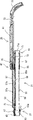
電気掃除機1は、図1に示すように、掃除機本体3、接続体5、吸込口体7を備える。接続体5は掃除機本体3と吸込口体7とを着脱自在に接続する。電気掃除機1は、フローリングやカーペット等の清掃面上の塵埃等を吸込口体7から吸込み、接続体5を介して掃除機本体3内に吸引する。
ここで、塵埃等が吸込口体7から掃除機本体3の内部まで吸引される流路を吸引路とする。吸引路において、吸込口体7が位置する「側」を「上流側」とし、掃除機本体3が位置する「側」を「下流側」とする。
また、電気掃除機1を使用する使用者から見て、吸込口体7が存在する側を前側とし、掃除機本体3が存在する側を後側とする。吸込口体7と掃除機本体3とを結ぶ方向を前後方向といい(図1参照)、前後方向と直交する方向を「左右方向」という(図1参照)。また、清掃面に対して直交する方向を、単に「上下方向」といい、清掃面から離れる側を「上側」、清掃面に近づく側を「下側」とそれぞれいう。
以下、各構成の概略を説明する。
<Embodiment>
Next, a first embodiment will be described with reference to FIGS.
1. Outline of Vacuum Cleaner As shown in FIG. 1, the vacuum cleaner 1 includes a vacuum cleaner body 3, a connection body 5, and a suction port body 7. The connection body 5 detachably connects the cleaner body 3 and the suction port body 7. The vacuum cleaner 1 sucks dust or the like on a cleaning surface such as flooring or carpet from the suction port body 7 and sucks it into the cleaner body 3 through the connection body 5.
Here, a flow path through which dust or the like is sucked from the suction port body 7 to the inside of the cleaner body 3 is defined as a suction path. In the suction path, the “side” where the suction port 7 is located is referred to as “upstream side”, and the “side” where the cleaner body 3 is located is referred to as “downstream side”.
Further, when viewed from the user who uses the vacuum cleaner 1, the side where the suction port 7 is present is the front side, and the side where the vacuum cleaner body 3 is present is the rear side. The direction connecting the suction port body 7 and the cleaner body 3 is referred to as the front-rear direction (see FIG. 1), and the direction orthogonal to the front-rear direction is referred to as the “left-right direction” (see FIG. 1). The direction perpendicular to the cleaning surface is simply referred to as “vertical direction”, the side away from the cleaning surface is referred to as “upper side”, and the side approaching the cleaning surface is referred to as “lower side”.
Hereinafter, an outline of each component will be described.

(1)掃除機本体
掃除機本体3は、塵埃等を吸引するための電動送風機と、電動送風機よりも上流側に配された集塵スペースとを筐体11内に備える。集塵方式は、サイクロン式でもよいし、紙パック式でもよいし、両者を併用してもよい。ここでは、紙パック式を利用している。
掃除機本体3は、接続体5が着脱自在に接続される接続部13を筐体11に備える。接続部13は集塵スペースと連通する流路を内部に有している。
筐体11は、集塵スペースに対応する部位に取出口を有する筐体本体15と、筐体本体15の取出口を開閉自在に閉じる蓋体17とを有する。接続部13を通って集塵スペース(紙パック)に集塵された塵埃等は、蓋体17を開けることで、取出口を介して取り出される。
掃除機本体3は、キャニスタ式であり、移動補助用の車輪19や、方向変換用の車輪等を筐体11に備えている。
(1) Vacuum Cleaner Body The vacuum cleaner body 3 includes an electric blower for sucking dust and the like, and a dust collection space disposed upstream of the electric blower in the housing 11. The dust collection method may be a cyclone type, a paper pack type, or a combination of both. Here, a paper pack type is used.
The vacuum cleaner main body 3 includes a housing 11 having a connection portion 13 to which the connection body 5 is detachably connected. The connection part 13 has a flow path communicating with the dust collection space.
The casing 11 includes a casing main body 15 having an outlet at a portion corresponding to the dust collection space, and a lid 17 that closes the outlet of the casing main body 15 so as to be freely opened and closed. Dust collected in the dust collection space (paper pack) through the connection portion 13 is taken out through the outlet by opening the lid 17.
The cleaner body 3 is of a canister type, and includes a movement assisting wheel 19, a direction changing wheel, and the like in the housing 11.

(2)接続体
接続体5は、接続管21、ホース23、取手25を備えている。
接続管21は接続体5における吸引路の上流側に位置する。接続管21の上流側端である上流側口部27は吸込口体7と着脱自在に接続される。ホース23は可撓性を有する湾曲自在な筒体で構成される。ホース23は接続体5における吸引路の下流側に位置する。ホース23の下流側端である下流側口部29は掃除機本体3の接続部13に着脱自在に接続される。
接続管21の下流側端は、接続管21の内部とホース23の内部とが連通する状態で、ホース23の上流側端に接続される。これにより、接続体5内に吸引路の一部が形成される。
(2) Connection body The connection body 5 includes a connection pipe 21, a hose 23, and a handle 25.
The connection pipe 21 is located on the upstream side of the suction path in the connection body 5. An upstream port 27 that is an upstream end of the connection pipe 21 is detachably connected to the suction port body 7. The hose 23 is composed of a flexible and flexible tube. The hose 23 is located on the downstream side of the suction path in the connection body 5. A downstream port portion 29 that is a downstream end of the hose 23 is detachably connected to the connection portion 13 of the cleaner body 3.
The downstream end of the connecting pipe 21 is connected to the upstream end of the hose 23 in a state where the inside of the connecting pipe 21 and the inside of the hose 23 communicate with each other. As a result, a part of the suction path is formed in the connection body 5.

取手25は、接続管21の管軸の延伸する方向(以下、「管軸方向」という。)に移動可能に接続管21に設けられている。これにより、取手25は、接続管21の下流側端から延伸する延伸長さが調整可能となる。なお、管軸方向は、管軸が延伸する方向だけでなく、管軸と平行な方向も含む。
取手25の接続管21からの延伸長さが最小となる状態で、接続管21の下流側端に近い側の端部は、操作者が掃除する際に把持するハンドル部31となっている。
取手25は、掃除機本体3の電動送風機の駆動・停止を操作したり、吸込口体7の回転ブラシの回転・停止を操作したり、吸引力の強弱を選択したりするためのスイッチ操作部33を有している。
取手25におけるハンドル部31と反対側の端部には、接続管21に対する位置調整を行うための位置調整操作部35を有している。なお、取手25におけるハンドル部31と反対側の端部は、本発明の「移動部」の一例に相当する。
なお、接続体5における接続管21と取手25の詳細については、後述する
The handle 25 is provided on the connection pipe 21 so as to be movable in a direction in which the pipe axis of the connection pipe 21 extends (hereinafter referred to as “tube axis direction”). Thereby, the handle 25 can adjust the extending length extending from the downstream end of the connecting pipe 21. The tube axis direction includes not only the direction in which the tube axis extends, but also the direction parallel to the tube axis.
In a state where the extension length of the handle 25 from the connection pipe 21 is minimized, the end portion on the side close to the downstream end of the connection pipe 21 is a handle portion 31 that is gripped when the operator cleans.
The handle 25 is a switch operation unit for operating driving / stopping of the electric blower of the cleaner body 3, operating rotation / stopping of the rotating brush of the suction port body 7, and selecting the strength of the suction force. 33.
At the end of the handle 25 opposite to the handle portion 31, there is a position adjusting operation portion 35 for adjusting the position with respect to the connecting pipe 21. The end portion of the handle 25 opposite to the handle portion 31 corresponds to an example of the “moving portion” in the present invention.
The details of the connection pipe 21 and the handle 25 in the connection body 5 will be described later.

(3)吸込口体
吸込口体7は、例えば、吸込部41、ジョイント部43、継手部45を有し、継手部45が接続管21の上流側口部27に着脱自在に接続される。
吸込部41は、左右方向に延伸する第1吸込空間と、前後方向に延伸する第2吸込空間とを連通状態で内部に有する。吸込部41は、清掃面と対向する対向面(底面)に塵埃等を吸込むための吸込口を第1吸込空間の開口として有している。第1吸込空間には、例えば、回転ブラシが設けられている。なお、回転ブラシが設けられていなくてもよい。
ジョイント部43および継手部45は第2吸込空間に連通する空間を内部に有している。ジョイント部43は、吸込部41に対して、例えば、前後方向を回転中心として回転自在に設けられている。継手部45は、ジョイント部43に対して、例えば、左右方向を回転中心として回転自在(上下方向に起伏自在)に設けられている。
(3) Suction Port Body The suction port body 7 includes, for example, a suction portion 41, a joint portion 43, and a joint portion 45, and the joint portion 45 is detachably connected to the upstream side mouth portion 27 of the connection pipe 21.
The suction part 41 has a first suction space extending in the left-right direction and a second suction space extending in the front-rear direction inside in a communicating state. The suction part 41 has a suction port for sucking dust and the like as an opening of the first suction space on a facing surface (bottom surface) facing the cleaning surface. For example, a rotating brush is provided in the first suction space. Note that the rotating brush may not be provided.
The joint part 43 and the joint part 45 have a space communicating with the second suction space. The joint portion 43 is provided so as to be rotatable with respect to the suction portion 41, for example, with the front-rear direction as a rotation center. The joint portion 45 is provided so as to be rotatable with respect to the joint portion 43, for example, with the right and left direction as the center of rotation (can be raised and lowered in the vertical direction).

2.接続管と取手
取手25は、上述の概略説明のように、接続管21からの延伸長さが調整自在な状態で接続管21に設けられている。例えば、取手25は、接続管21に対して移動自在に取り付けられる取付部47をハンドル部31と反対側の端部に有している。
取手25の延伸長さが最小の状態では、図2および図3に示すように、取付部47が接続管21の上流側口部27に最も近づく。取手25の延伸長さが最大の状態では、図4および図5に示すように、取付部47が接続管21の下流側端部49に最も近づく。
接続管21又は取手25には、取付部47が上流側口部(把持部)27に近づいた際に取付部47と上流側口部27とが当接(接触)するのを規制する規制部53が設けられている。
2. Connection pipe and handle The handle 25 is provided in the connection pipe 21 in a state in which the extension length from the connection pipe 21 is adjustable as described above. For example, the handle 25 has an attachment portion 47 that is movably attached to the connection pipe 21 at the end opposite to the handle portion 31.
In the state where the extending length of the handle 25 is minimum, the attachment portion 47 is closest to the upstream side mouth portion 27 of the connection pipe 21 as shown in FIGS. In the state where the extending length of the handle 25 is maximum, the attachment portion 47 is closest to the downstream end portion 49 of the connection pipe 21 as shown in FIGS. 4 and 5.
The connecting pipe 21 or the handle 25 restricts the attachment portion 47 and the upstream side port 27 from contacting (contacting) when the mounting unit 47 approaches the upstream side port (gripping unit) 27. 53 is provided.

(1)接続管 接続管21は、図2〜図5に示すように、上流側から、上流側口部27、筒部55、下流側端部49の順で有している。接続管21は、筒部55と間隔おいて筒部55と平行に延伸する延伸部57を有している。
(あ)筒部
筒部55は、塵埃等が通過する吸引路を構成する空間55aを管軸方向に沿って内部に有している。筒部55は、管軸方向と直交する断面(以下、「横断面」という。)の形状および寸法は、ここでは、管軸方向に移動したときに変化せずに一定であるが、形状および寸法は変化してもよい。筒部55の横断面形状は、非円形状をしている。ここでは、筒部55の横断面形状は、上下方向に長い長円形状に似た形状をしている。
筒部55は、図3や図5に示すように、内部が上記空間55aである筒部分59を有している。筒部55は、筒部分59における延伸部57が存在する側に、配線収容部分61を有している。配線収容部分61は、掃除機本体3の電動風送機と電気的に接続された駆動用配線(図示省略)を収容する。この駆動用配線は、後述の把持部27内に収容されている端子部に接続される。
(1) Connection pipe As shown in FIGS. 2 to 5, the connection pipe 21 has an upstream side port 27, a cylindrical portion 55, and a downstream end portion 49 in this order from the upstream side. The connecting pipe 21 has an extending portion 57 that extends in parallel with the cylindrical portion 55 at a distance from the cylindrical portion 55.
(A) Cylinder part The cylinder part 55 has the space 55a which comprises the suction path through which dust etc. pass inside along the pipe-axis direction. The cylindrical portion 55 has a shape and a dimension that are constant without changing when moved in the tube axis direction, although the shape and size of a cross section orthogonal to the tube axis direction (hereinafter referred to as a “cross section”) are constant. The dimensions may vary. The cross-sectional shape of the cylinder part 55 is non-circular. Here, the cross-sectional shape of the cylindrical portion 55 is similar to an oval shape that is long in the vertical direction.
As shown in FIGS. 3 and 5, the cylindrical portion 55 has a cylindrical portion 59 whose inside is the space 55 a. The tube portion 55 has a wiring housing portion 61 on the side of the tube portion 59 where the extending portion 57 exists. The wiring accommodating portion 61 accommodates a driving wiring (not shown) that is electrically connected to the electric fan of the cleaner body 3. This drive wiring is connected to a terminal portion accommodated in a grip portion 27 described later.

(い)上流側口部(把持部)
上流側口部27は、吸引路の一部を構成する空間63aを内部に有する上流側筒部63を有している。空間63aは、接続管21の管軸に沿って伸び、筒部55の内部の空間55aに連続する。
上流側口部27は、横断面において、筒部55よりも大きな部分を有する。ここでは、上流側筒部63の上面に設けられた端子収容部65が上記大きな部分に相当する。端子収容部65の上面は筒部55の上面よりも高い。これにより、筒部55と上流側口部27との間に段差が形成される。
なお、上流側口部27は、取手25を接続管21に対して移動させる際に、使用者が把持する部分として機能する可能性が高い。つまり、ここでは、上流側口部27は把持部としても構成され、把持部の符号も「27」を用いる。
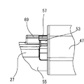
端子収容部65には、筒部55内に配された駆動用配線と、延伸部57内に配されたスイッチ用配線とを接続する端子(図示省略)が収容されている。なお、端子収容部65には、吸込口体7の上流側口部27への装着状態を解除する解除手段67が設けられている。
端子収容部65の上面であって筒部55側に延伸部57のベース部分69が設けられている。ベース部分69は中空状であり、延伸部57内に配されているスイッチ用配線が端子収容部65へと導出されるようになっている。
(Ii) Upstream side mouth (grip)
The upstream side mouth part 27 has an upstream side cylinder part 63 having a space 63a constituting a part of the suction path inside. The space 63 a extends along the tube axis of the connection pipe 21 and continues to the space 55 a inside the cylindrical portion 55.
The upstream side mouth portion 27 has a portion larger than the cylindrical portion 55 in the cross section. Here, the terminal accommodating part 65 provided in the upper surface of the upstream cylinder part 63 is equivalent to the said big part. The upper surface of the terminal accommodating portion 65 is higher than the upper surface of the cylindrical portion 55. Thereby, a step is formed between the cylindrical portion 55 and the upstream side mouth portion 27.
In addition, when moving the handle 25 with respect to the connection pipe 21, the upstream side port part 27 has a high possibility of functioning as a part which a user holds. That is, here, the upstream side port portion 27 is also configured as a gripping portion, and the symbol of the gripping portion uses “27”.
The terminal accommodating portion 65 accommodates a terminal (not shown) that connects the drive wiring disposed in the cylindrical portion 55 and the switch wiring disposed in the extending portion 57. The terminal accommodating portion 65 is provided with a release means 67 for releasing the mounting state of the suction port body 7 on the upstream side mouth portion 27.
A base portion 69 of the extending portion 57 is provided on the upper surface of the terminal accommodating portion 65 and on the cylindrical portion 55 side. The base portion 69 is hollow, and the switch wiring arranged in the extending portion 57 is led out to the terminal accommodating portion 65.

(う)下流側端部
下流側端部49は、吸引路の一部を構成する空間71aを内部に有する下流側筒部71を有している。空間71aは、接続管21の管軸に沿って伸び、筒部55の内部の空間55aに連続する。
下流側端部49は、断面において、筒部55よりも大きな部分を有する。ここでは、筒部55よりも直径が大きい大径部となっている。大径部は、下流側筒部71の外周に設けられた大径筒部73により構成される。つまり、下流側端部49は、下流側筒部71と大径筒部73とを有している。
大径筒部73は、横断面において延伸部57が存在する側に、取手25をスライド自在に支持する支持手段を構成する支持部74を有している。ここでの「延伸部57が存在する側」は上側である。つまり、支持部74は、大径筒部73の上部に存在する。
(U) Downstream end part The downstream end part 49 has the downstream cylinder part 71 which has the space 71a which comprises some suction paths inside. The space 71 a extends along the tube axis of the connecting tube 21 and continues to the space 55 a inside the cylindrical portion 55.
The downstream end portion 49 has a portion larger than the cylindrical portion 55 in the cross section. Here, the large-diameter portion is larger in diameter than the cylindrical portion 55. The large diameter portion is configured by a large diameter cylindrical portion 73 provided on the outer periphery of the downstream side cylindrical portion 71. That is, the downstream side end portion 49 has the downstream side cylindrical portion 71 and the large diameter cylindrical portion 73.
The large-diameter cylindrical portion 73 has a support portion 74 constituting a support means for slidably supporting the handle 25 on the side where the extending portion 57 exists in the cross section. Here, the “side where the extending portion 57 exists” is the upper side. That is, the support portion 74 exists at the upper portion of the large diameter cylindrical portion 73.

(え)延伸部
延伸部57は、取手25の接続管21からの延伸長さが最大の状態で、延伸部57の先端が取手25内に位置する長さを有している。延伸部57は、中空状且つ延伸先端は開放状に構成されている。延伸部57の横断面形状は、非円形状をしている。横断面形状は、例えば、左右方向に広い扁平状をしている。延伸部57の内部には、スイッチ用配線が収容されている。
取手25と接続管21とには、取手25の接続管21に対する位置を固定する位置決め手段が設けられている。ここでは、位置決め手段は、凹部と凸部とを有し、凸部が凹部に入り込む(係合する)ことで、取手25が接続管21に位置決めされる。なお、位置決めの固定・解除は、使用者の位置調整操作部35の操作により行われる。
位置決め手段の凹部57aは、延伸部57の上面に設けられている。凹部57aは、延伸部57の延伸方向に間隔をおいて複数個設けられている。なお、凸部は、取手25の内部に設けられている。
(E) Extending portion The extending portion 57 has such a length that the extension length of the handle 25 from the connecting pipe 21 is the maximum, and the tip of the extending portion 57 is located in the handle 25. The extending portion 57 is formed in a hollow shape and the extending tip is open. The cross-sectional shape of the extending portion 57 is non-circular. The cross-sectional shape is, for example, a flat shape wide in the left-right direction. A switch wiring is accommodated inside the extending portion 57.
The handle 25 and the connecting pipe 21 are provided with positioning means for fixing the position of the handle 25 with respect to the connecting pipe 21. Here, the positioning means has a concave portion and a convex portion, and the handle 25 is positioned on the connecting pipe 21 by the convex portion entering (engaging) the concave portion. The positioning is fixed / released by the user's operation of the position adjustment operation unit 35.
A recess 57 a of the positioning means is provided on the upper surface of the extending portion 57. A plurality of the recessed portions 57 a are provided at intervals in the extending direction of the extending portion 57. The convex portion is provided inside the handle 25.

(お)規制部
規制部53は、取付部47と把持部(下流側口部)27との間に設けられている。規制部53は、筒部55と延伸部57との間に設けられている。具体的には、把持部27と筒部55に跨って形成されている。規制部53は、筒部55の上面から上方に突出する凸部により構成されている。なお、凸部における上流側の端部は、把持部27とつながっている。
(O) Restricting part The restricting part 53 is provided between the mounting part 47 and the grip part (downstream port part) 27. The restricting portion 53 is provided between the tube portion 55 and the extending portion 57. Specifically, it is formed across the grip portion 27 and the cylinder portion 55. The restricting portion 53 includes a convex portion that protrudes upward from the upper surface of the cylindrical portion 55. Note that the upstream end of the convex portion is connected to the grip portion 27.

(2)取手
取手25は、取手筒部81、取付部47、ハンドル部31、スイッチ操作部33、位置調整操作部35を有し、取付部47が接続管21の筒部55に嵌合(すきま嵌め)することで、接続管21の管軸方向に移動可能となる。
(あ)取手筒部
取手筒部81は、接続管21に沿って直管状に延伸する筒状をしている。取手筒部81は、筒部55と間隔を置いて平行に設けられている。間隔を置く方向は、筒部55を基準にして延伸部57が設けられている側であり、ここでは筒部55の上方となる。
取手筒部81は、接続管21の延伸部57を挿抜自在に収納する。取手筒部81は、横断面形状において、延伸部57の横断面形状に似た、左右方向に広い扁平状をしている。取手筒部81における筒部55との対向面(下面である)には、支持手段を構成する被支持部83が設けられている。ここでの被支持部83は、下方に突出した下端部から左右の両方向に突出する嵌合凸部83aを有している。また、嵌合凸部83aは、管軸方向に沿って延伸している。
(2) Handle The handle 25 has a handle tube portion 81, an attachment portion 47, a handle portion 31, a switch operation portion 33, and a position adjustment operation portion 35, and the attachment portion 47 is fitted to the tube portion 55 of the connection pipe 21 ( It becomes possible to move in the tube axis direction of the connecting pipe 21 by performing a clearance fit.
(A) Handle cylinder part The handle cylinder part 81 is carrying out the cylinder shape extended | stretched in a straight tube form along the connection pipe 21. As shown in FIG. The handle cylinder part 81 is provided in parallel with the cylinder part 55 at an interval. The direction in which the interval is set is the side on which the extending portion 57 is provided with respect to the cylindrical portion 55, and is above the cylindrical portion 55 here.
The handle cylinder part 81 accommodates the extending part 57 of the connecting pipe 21 so that it can be inserted and removed. The handle cylinder portion 81 has a flat shape that is wide in the left-right direction, similar to the cross-sectional shape of the extending portion 57, in the cross-sectional shape. A supported portion 83 constituting a supporting means is provided on a surface (lower surface) of the handle tube portion 81 facing the tube portion 55. The supported portion 83 here has a fitting convex portion 83a that protrudes in both the left and right directions from a lower end portion that protrudes downward. Moreover, the fitting convex part 83a is extended | stretched along the pipe-axis direction.

(い)取付部
取付部47は、取手筒部81におけるハンドル部31と反対側に位置する端部の下部に設けられている。取付部47は、筒部55に対して摺動可能に嵌合する嵌合部分85を有している。嵌合部分85は、筒部55の外周を全周に亘って嵌合する。換言すると、取付部47は、筒部55の横断面における外周形状と一致する形状貫通孔を有し、この貫通孔に筒部55が挿通することで筒部55に対して摺動可能に嵌合している。
取付部47は、嵌合部分85における貫通孔の下方から筒部55の管軸と平行に延出する延出部分87を有している。延出部分87は、接続管21の大径筒部73に向かって延出している。延出部分87は、横断面において、筒部55の外周の下面側に当接する形状の上面を有している。換言すると、延出部分87は、筒部55を下方から受ける受け部分として機能する。
延出部分87は、図4に示すように、取手25の接続管21からの延伸長さが最大となったときに、大径筒部73と当接する。この当接状態では、取付部47と大径筒部73との間に隙間ができる。この隙間は、人の指が入るのに十分な隙間なので、延伸長さが最大になったときでも取付部47と大径筒部73との間で指を挟むことがない。
(I) Attachment part The attachment part 47 is provided in the lower part of the edge part located in the handle cylinder part 81 on the opposite side to the handle part 31. As shown in FIG. The attachment portion 47 has a fitting portion 85 that is slidably fitted to the cylindrical portion 55. The fitting part 85 fits the outer periphery of the cylinder part 55 over the entire circumference. In other words, the attachment portion 47 has a shape through-hole that matches the outer peripheral shape of the cross-section of the cylinder portion 55, and the cylinder portion 55 is inserted into the through-hole so as to be slidable with respect to the cylinder portion 55. Match.
The attachment portion 47 has an extending portion 87 that extends in parallel with the tube axis of the cylindrical portion 55 from below the through hole in the fitting portion 85. The extending portion 87 extends toward the large diameter cylindrical portion 73 of the connecting pipe 21. The extending portion 87 has an upper surface shaped so as to be in contact with the lower surface side of the outer periphery of the cylindrical portion 55 in the cross section. In other words, the extended portion 87 functions as a receiving portion that receives the cylindrical portion 55 from below.
As shown in FIG. 4, the extended portion 87 comes into contact with the large-diameter cylindrical portion 73 when the extension length of the handle 25 from the connection pipe 21 is maximized. In this contact state, a gap is formed between the mounting portion 47 and the large diameter cylindrical portion 73. Since this gap is sufficient for a human finger to enter, even when the stretched length is maximized, the finger is not sandwiched between the attachment portion 47 and the large-diameter cylindrical portion 73.

(う)ハンドル部およびスイッチ操作部
ハンドル部31は、取手筒部81の端部に設けられ、湾曲形状をしている。湾曲する方向は、図1に示すように、電気掃除機1の使用時にハンドル部31が水平方向になる方向である。
スイッチ操作部33は、取手筒部81の端部側の上部側に設けられている。つまり、使用者の操作性を向上させるため、スイッチ操作部33は取手筒部81におけるハンドル部31に近い位置に設けられている。
なお、スイッチ操作部33は、後述する基板と、基板に取り付けられたスイッチ32とからなる。
(U) Handle portion and switch operation portion The handle portion 31 is provided at the end of the handle tube portion 81 and has a curved shape. As shown in FIG. 1, the bending direction is a direction in which the handle portion 31 is horizontal when the electric vacuum cleaner 1 is used.
The switch operation unit 33 is provided on the upper side on the end side of the handle tube unit 81. That is, in order to improve the operability for the user, the switch operation portion 33 is provided at a position near the handle portion 31 in the handle tube portion 81.
The switch operation unit 33 includes a substrate described later and a switch 32 attached to the substrate.

(え)位置調整操作部
位置調整操作部35は、取手筒部81における取付部47の近くに設けられている。位置調整操作部35は、ここでは、押しボタン式が利用され、この押しボタン(35a)を押すと、延伸部57の凹部57aに入り込んでいた凸部(35b)の係合が解除され、取手25が接続管21に対して移動可能となる。
(E) Position Adjustment Operation Part The position adjustment operation part 35 is provided near the attachment part 47 in the handle tube part 81. Here, the position adjustment operation unit 35 is a push button type. When the push button (35a) is pressed, the engagement of the convex portion (35b) that has entered the concave portion 57a of the extending portion 57 is released. 25 becomes movable with respect to the connecting pipe 21.

3.使用例
(1)使用時
電気掃除機1は、取手25を接続管21に対して縮めた状態で、保管されることが多い。このため、使用時には、使用者の使い勝手のよい位置に取手25を接続管21に対して移動させて、取手25の接続管21からの延伸長さを調整する。
この調整は、使用者は、接続管21の把持部27を一方の手で把持し、他方の手で位置調整操作部35を操作しながら取手25の取付部47を接続管21の大径筒部73側に移動させることで、行われる。
この際、例えば、取手25の延伸長さを最大にするときに、つまり、取付部51を大径筒部73に近づけたときに、取付部51の延出部分87が大径筒部73に当接する。当接した状態では、取付部51大径筒部73との間に隙間ができる。このため、取付部51と大径筒部73との間に使用者の指を挟むようなことを少なくできる。特に、延出部分87は、取付部51の下部側に存在するため、延出部分87の先端付近に使用者の指が存在することが少ない。
3. Usage example (1) During use The vacuum cleaner 1 is often stored in a state where the handle 25 is contracted with respect to the connecting pipe 21. For this reason, at the time of use, the handle 25 is moved with respect to the connection pipe 21 to a position convenient for the user, and the extension length of the handle 25 from the connection pipe 21 is adjusted.
In this adjustment, the user holds the grip portion 27 of the connection pipe 21 with one hand, and operates the position adjustment operation portion 35 with the other hand, and attaches the attachment portion 47 of the handle 25 to the large-diameter tube of the connection pipe 21. It is performed by moving to the part 73 side.
At this time, for example, when the extending length of the handle 25 is maximized, that is, when the attachment portion 51 is brought close to the large-diameter cylindrical portion 73, the extended portion 87 of the attachment portion 51 becomes the large-diameter cylindrical portion 73. Abut. In the abutted state, a gap is formed between the attachment portion 51 and the large-diameter cylindrical portion 73. For this reason, it can reduce that a user's finger | toe is pinched between the attaching part 51 and the large diameter cylinder part 73. FIG. In particular, since the extended portion 87 exists on the lower side of the attachment portion 51, the user's finger is rarely present near the tip of the extended portion 87.

(2)保管時
清掃面の掃除が終了すると、電気掃除機1は片付けられる(保管される)。この保管される際の電気掃除機1の取手25は、接続管21に対して縮められた状態であることが多い。
取手25の縮めは、取手25の延伸長さの調整と同様に行われる。つまり、使用者は、接続管21の把持部27を一方の手で把持し、他方の手で位置調整操作部35を操作しながら取手25の取付部51を接続管21の把持部27側に移動させる。
この際、把持部27と取付部51との間に規制部53が存在している。このため、把持部27と取付部51との面同士が当接することはなく、取手25を縮める際に使用者の手を挟むような危険性がなくなる。
特に、規制部53は、接続管21の延伸部57と筒部55との間に設けられているので、規制部53は延伸部57の影となり、規制部53と取付部51との間に使用者の指が入り難い構造となっている。
また、規制部53と取付部51とが当接した状態では、把持部27と取付部51との間に隙間ができる。このため、例えば、規制部がなく、把持部27と取付部51とが当接する際に把持部27と取付部51との間に指が挟まれるような握り方で取手25を縮めても、規制部53のある本実施形態の電気掃除機1では、けがするようなことを少なくできる。
(2) During storage When the cleaning of the cleaning surface is completed, the vacuum cleaner 1 is cleared (stored). The handle 25 of the vacuum cleaner 1 when stored is often in a state of being contracted with respect to the connecting pipe 21.
The shrinkage of the handle 25 is performed in the same manner as the adjustment of the extending length of the handle 25. That is, the user holds the grip portion 27 of the connection pipe 21 with one hand, and operates the position adjustment operation portion 35 with the other hand, and moves the attachment portion 51 of the handle 25 toward the grip portion 27 side of the connection pipe 21. Move.
At this time, the restricting portion 53 exists between the grip portion 27 and the attachment portion 51. For this reason, the surfaces of the grip portion 27 and the attachment portion 51 do not come into contact with each other, and there is no danger of pinching the user's hand when the handle 25 is contracted.
Particularly, since the restricting portion 53 is provided between the extending portion 57 and the cylindrical portion 55 of the connecting pipe 21, the restricting portion 53 is a shadow of the extending portion 57 and is between the restricting portion 53 and the mounting portion 51. The user's fingers are difficult to enter.
Further, in a state where the restricting portion 53 and the attachment portion 51 are in contact with each other, a gap is formed between the grip portion 27 and the attachment portion 51. For this reason, for example, even if the handle 25 is shrunk in such a way that a finger is sandwiched between the gripping part 27 and the mounting part 51 when the gripping part 27 and the mounting part 51 come into contact with each other, In the vacuum cleaner 1 of the present embodiment having the restricting portion 53, it is possible to reduce injuries.

4.実施例
(1)接続管
接続管21は、図8に示すように、接続本体101、接続本体カバー103、解除手段67、段付チャンネル材105、チャンネルカバー107、一対の半割筒体109から主に構成される。なお、配線収容部分61内に配される駆動用配線および延伸部57内に配されるスイッチ用配線の図示は省略している。
接続本体101は、内部に吸引路を構成する吸引空間111を全長に亘って内部に有している。接続本体101の上部は平坦状を有し、この平坦な部分に、端子や配線を固定するボスや補強用のリブ等が形成されている。
接続本体101の一方の端部101aは、上流側口部27の上流側筒部63に相当し、端部101aの上面が、段付チャンネル材105の一端の下段部113により覆われる。このとき、下段部113の開口113aから解除ボタン67aが露出する状態で、解除手段67が内部に収容される。これにより端子収容部65が構成され、接続本体101の端部101aに接続管21の把持部27が構成される。
4). Example (1) Connection Pipe The connection pipe 21 is composed of a connection main body 101, a connection main body cover 103, a release means 67, a stepped channel member 105, a channel cover 107, and a pair of half cylinders 109, as shown in FIG. Mainly composed. In addition, illustration of the drive wiring arrange | positioned in the wiring accommodating part 61 and the switch wiring arrange | positioned in the extending | stretching part 57 is abbreviate | omitted.
The connection main body 101 has the suction space 111 which comprises a suction path in the inside over the full length. The upper portion of the connection main body 101 has a flat shape, and a boss for fixing terminals and wiring, a reinforcing rib, and the like are formed on the flat portion.
One end portion 101 a of the connection main body 101 corresponds to the upstream cylindrical portion 63 of the upstream port portion 27, and the upper surface of the end portion 101 a is covered with the lower step portion 113 of one end of the stepped channel member 105. At this time, the release means 67 is accommodated in the state where the release button 67a is exposed from the opening 113a of the lower step portion 113. Thus, the terminal accommodating portion 65 is configured, and the grip portion 27 of the connection tube 21 is configured at the end portion 101 a of the connection main body 101.

接続本体101の他方の端部101bは、下流側端部49の下流側筒部71に相当し、端部101bに一対の半割筒部109a,109bが取り付けられる。なお、一対の半割筒部109a,109bは、組み合わせると筒状となり、ここでは、上下方向から接続本体101の端部101bを挟持することで、大径筒部73が構成される。上側に取り付けられる半割筒部109bの上部は支持部74となっている。
接続本体101における両端部間の中間部101cは、接続管21の筒部分59に相当し、中間部101cの上面は、接続本体カバー103により覆われる。接続本体カバー103は横断面形状が逆「U」字状をし、接続本体101に装着されると内部に空間が形成される。これにより、配線収容部分61が構成され、この空間内に駆動用配線が配される。
段付チャンネル材105は延伸部57の一部を構成する。段付チャンネル材105の上段部114は横断面形状が逆「U」字状をし、下面の開口が板状のチャンネルカバー107により塞がれる。これにより、延伸部57が構成され、内部に空間が形成される。この空間にはスイッチ用配線が配される。
The other end 101b of the connection main body 101 corresponds to the downstream cylinder 71 of the downstream end 49, and a pair of half cylinders 109a and 109b are attached to the end 101b. The pair of half cylinder portions 109a and 109b are formed into a cylindrical shape when combined, and here, the large-diameter cylinder portion 73 is configured by sandwiching the end portion 101b of the connection main body 101 from the vertical direction. The upper part of the half cylinder part 109b attached to the upper side is a support part 74.
An intermediate portion 101 c between both end portions of the connection main body 101 corresponds to the cylindrical portion 59 of the connection pipe 21, and the upper surface of the intermediate portion 101 c is covered with the connection main body cover 103. The connection main body cover 103 has an inverted “U” shape in cross section, and a space is formed inside when the connection main body 101 is attached. Thereby, the wiring accommodating part 61 is comprised, and the wiring for a drive is distribute | arranged in this space.
The stepped channel material 105 constitutes a part of the extending portion 57. The upper step portion 114 of the stepped channel member 105 has an inverted “U” shape in cross section, and the opening on the lower surface is closed by the plate-like channel cover 107. Thereby, the extending | stretching part 57 is comprised and space is formed in an inside. Switch wiring is arranged in this space.

(2)取手
取手25は、図9に示すように、取手本体121、取手カバー123、スイッチ操作部33、嵌合部材125、受け部材127から主に構成される。
取手本体121は、横断面形状が「U」字状をした半筒状の半筒部131と、半筒部131の一方の端131aの下面(「U」字の開口が存在する側と反対側の面である。)に設けられた筒状部133とを有する。半筒部131は、直線状に延伸する直状延伸部分135と、直状延伸部分135の他方の端部から下方へ徐々に湾曲する曲状延伸部分137とを有する。
取手本体121の上部は取手カバー123により覆われる。取手カバー123も、取手本体121と同様に、直状延伸部141と曲状延伸部143とを有する。取手カバー123の横断面形状は半円状をし、取手本体121が取手カバー123により覆われることにより、内部に空間が形成される。この空間は、接続管21の延伸部37が収容される空間となる。
(2) Handle As shown in FIG. 9, the handle 25 mainly includes a handle main body 121, a handle cover 123, a switch operation unit 33, a fitting member 125, and a receiving member 127.
The handle main body 121 includes a semi-cylindrical half-cylindrical portion 131 having a “U” -shaped cross section, and a lower surface of one end 131a of the semi-cylindrical portion 131 (opposite to the side where the “U” -shaped opening exists). A cylindrical portion 133 provided on the side surface). The semi-cylindrical portion 131 includes a straight extending portion 135 that extends linearly and a curved extending portion 137 that gradually curves downward from the other end of the straight extending portion 135.
The upper part of the handle body 121 is covered with a handle cover 123. The handle cover 123 also has a straight extending portion 141 and a curved extending portion 143, similarly to the handle main body 121. The cross-sectional shape of the handle cover 123 is semicircular, and the handle main body 121 is covered with the handle cover 123, so that a space is formed inside. This space is a space in which the extending portion 37 of the connecting pipe 21 is accommodated.

この空間には、スイッチ操作部33や位置調整操作部35が収容される。スイッチ操作部33は、基板34とスイッチ32とを備えている。なお、スイッチ32は、ボタン式であり、取手カバー123の貫通孔141aを介して外部に露出し、保護カバー145により保護される。位置調整操作部35は、その押しボタン35aが取手カバー123の貫通孔141bを介して外部に露出し、延伸部57の凹部57aに入り込む凸部35bが収容され、構成される。
筒状部133の内部には、嵌合部材125と受け部材127が挿入される。これにより取付部51が構成される。嵌合部材125は、筒状部133における曲状延伸部分137と反対側の開口を塞ぐように筒状部133に挿入される。嵌合部材125は、延伸部57を取手25内に受け入れるための受入口147と、筒部55の外周面に沿って当接する当接部149とを有する。
受け部材127は、筒状部133内に配され且つ筒部55の下面外周に沿って当接する当接部151と、筒状部133から曲状延伸部分137側に延出し且つ筒部55の外周面に沿って当接する延出部分153を有する。この延出部分153が延出部分87に相当する。
In this space, the switch operation unit 33 and the position adjustment operation unit 35 are accommodated. The switch operation unit 33 includes a substrate 34 and a switch 32. The switch 32 is a button type, is exposed to the outside through the through hole 141a of the handle cover 123, and is protected by the protective cover 145. The position adjustment operation unit 35 is configured by accommodating a projection 35 b whose push button 35 a is exposed to the outside through the through hole 141 b of the handle cover 123 and entering the recess 57 a of the extending portion 57.
A fitting member 125 and a receiving member 127 are inserted into the cylindrical portion 133. Thereby, the attaching part 51 is comprised. The fitting member 125 is inserted into the cylindrical portion 133 so as to close the opening on the opposite side of the curved extending portion 137 in the cylindrical portion 133. The fitting member 125 includes a receiving port 147 for receiving the extending portion 57 in the handle 25, and a contact portion 149 that contacts the outer peripheral surface of the cylindrical portion 55.
The receiving member 127 is disposed in the tubular portion 133 and abuts along the outer periphery of the lower surface of the tubular portion 55. The receiving member 127 extends from the tubular portion 133 toward the curved extension portion 137, and It has the extension part 153 contact | abutted along an outer peripheral surface. This extension portion 153 corresponds to the extension portion 87.

5.規制部
規制部53は、筒部55の周面と把持部27の端面とに跨る状態で設けられている。しかしながら、規制部は、把持部と取付部とが当接するのを規制できればよく、図10に示すような規制部201,211であってもよい。
図10の(a)に示す規制部201は、筒部55の上面であって把持部27から離れた位置に設けられ、筒部55の上面から延伸部57に向けて突出する。なお、ここでは、規制部201は、筒部55の上面から延伸部57との間に隙間203が存在するように突出しているが、突出先が延伸部57に達してもよい。
図10の(b)に示す規制部211は、取付部47における把持部27と対向する面に設けられ、延伸部57の下面に沿って把持部27側に突出する。このように規制部211を取手(取付部47)側に設ける場合、規制部は筒部55と延伸部57との間に存在するのが好ましい。したがって、規制部は、筒部と延伸部の間に隙間(213)が存在するように取付部に設けられてもよいし、隙間ができないように取付部に設けられてもよい。
また、接続管21に延伸部57が存在する場合、規制部は延伸部57と筒部55との間に存在するのが好ましい。これは、延伸部57と筒部55との間に使用者の指が入りにくく、規制部と取付部とで指が挟まれたり、規制部と把持部とで指が挟まれたりするようなことを抑制できるからである。
5. Restricting part The restricting part 53 is provided in a state straddling the peripheral surface of the cylinder part 55 and the end face of the grip part 27. However, the restricting portion only needs to be able to restrict the gripping portion and the attachment portion from coming into contact with each other, and may be restricting portions 201 and 211 as shown in FIG.
The restricting portion 201 shown in FIG. 10A is provided on the upper surface of the cylindrical portion 55 at a position away from the gripping portion 27 and protrudes from the upper surface of the cylindrical portion 55 toward the extending portion 57. Here, the restricting portion 201 protrudes so that there is a gap 203 between the upper surface of the cylindrical portion 55 and the extending portion 57, but the protruding tip may reach the extending portion 57.
The restricting portion 211 shown in FIG. 10B is provided on the surface of the mounting portion 47 that faces the grip portion 27, and protrudes toward the grip portion 27 along the lower surface of the extending portion 57. When the restricting portion 211 is thus provided on the handle (attachment portion 47) side, the restricting portion is preferably present between the tubular portion 55 and the extending portion 57. Therefore, the restricting portion may be provided in the attachment portion so that a gap (213) exists between the tube portion and the extending portion, or may be provided in the attachment portion so that there is no gap.
In addition, when the extending portion 57 exists in the connecting pipe 21, it is preferable that the restricting portion exists between the extending portion 57 and the cylindrical portion 55. This is because it is difficult for a user's finger to enter between the extending portion 57 and the cylindrical portion 55, and the finger is pinched between the restricting portion and the mounting portion, or the finger is pinched between the restricting portion and the gripping portion. This is because it can be suppressed.

<変形例>
以上、実施形態に係る電気掃除機について説明したが、本発明は上記実施形態に限られるものではなく、例えば、以下のような変形例であってもよい。また、実施形態と変形例、変形例同士を組み合わせたものであってよい。
また、実施形態や変形例に記載していない例や、要旨を逸脱しない範囲の設計変更があっても本発明に含まれる。
<Modification>
Although the vacuum cleaner according to the embodiment has been described above, the present invention is not limited to the above-described embodiment, and may be modified as follows, for example. Further, the embodiment may be a combination of the modified example and the modified examples.
In addition, examples that are not described in the embodiments and modifications and design changes that do not depart from the gist are also included in the present invention.

1.電気掃除機
電気掃除機は、キャニスタ式であればよく、掃除機の構造は特に限定するものではない。例えば、接続体のホースは、接続管に対して着脱自在に取り付ける構造であってもよい。
また、電気掃除機は、電動送風機を利用したものをいい、商用電源にケーブルを介して接続されるケーブル有タイプでもよいし、充電器(蓄電池)を内蔵する、所謂充電タイプでもよい。
2.接続管
(1)延伸部
実施形態では、接続管21は筒部55と間隔をおいて延伸部57を有しているが、筒部と延伸部とが一体となった構造であってもよい。この場合も、把持部と移動部との間に規制部を設ければよい。例えば、接続管の外周面であって把持部と移動部との間に凸部を設けてもよい。この場合、凸部の高さは低い方が好ましい。これは、低いほど、把持部と移動部との間に指が挟まれ難くなるためである。
1. Vacuum Cleaner The vacuum cleaner may be a canister type, and the structure of the vacuum cleaner is not particularly limited. For example, the hose of the connection body may be structured to be detachably attached to the connection pipe.
Moreover, the vacuum cleaner refers to one using an electric blower, and may be a cable type connected to a commercial power supply via a cable, or may be a so-called charging type incorporating a charger (storage battery).
2. Connecting Pipe (1) Extending Part In the embodiment, the connecting pipe 21 has the extending part 57 spaced from the cylindrical part 55, but it may have a structure in which the cylindrical part and the extending part are integrated. . In this case as well, a restricting portion may be provided between the grip portion and the moving portion. For example, a convex portion may be provided between the gripping portion and the moving portion on the outer peripheral surface of the connecting pipe. In this case, it is preferable that the height of the convex portion is low. This is because the lower the finger is, the more difficult it is to pinch the finger between the grip portion and the moving portion.

(2)大径部
実施形態では、接続管21の下流側端部49に大径筒部73が設けられている。大径筒部73は、取手25の下流側への移動を規制する規制部としての機能を有する。しかしながら、他の手段で取手の下流側への移動を規制できれば、大径部とする必要はない。
他の手段として、例えば、下流側端部の外周面であって周方向に間隔をおいて突部により構成できる。また、本実施形態では、移動可能な取手の支持手段として、取手25に嵌合凸部(83)を、接続管21の大径筒部73に嵌合溝(74)をそれぞれ設けている。嵌合凸部は、接続管の管軸方向に沿って伸びており、嵌合凸部における取付部47に近い端部に嵌合溝(74)よりも大きな凸部を設けることで構成できる。
(3)配線収容部分
配線収容部分61は、筒部55の上部に設けられているが、下部に設けられてもよい。ただし、配線収容部分は、筒部分と取手との間に設けた方が好ましい。これは、配線収容部分が取手25により保護されるからである。
(2) Large diameter portion In the embodiment, the large diameter cylindrical portion 73 is provided at the downstream end portion 49 of the connection pipe 21. The large diameter cylindrical portion 73 has a function as a restricting portion that restricts the movement of the handle 25 to the downstream side. However, if the movement toward the downstream side of the handle can be restricted by other means, there is no need for the large diameter portion.
As another means, for example, it can be constituted by a protrusion on the outer peripheral surface of the downstream end and spaced in the circumferential direction. Moreover, in this embodiment, the fitting convex part (83) is provided in the handle 25, and the fitting groove | channel (74) is provided in the large diameter cylinder part 73 of the connection pipe 21, respectively as a movable handle support means. The fitting convex portion extends along the tube axis direction of the connecting pipe, and can be configured by providing a convex portion larger than the fitting groove (74) at an end portion of the fitting convex portion near the mounting portion 47.
(3) Wiring accommodating part The wiring accommodating part 61 is provided in the upper part of the cylinder part 55, However, You may provide in the lower part. However, it is preferable that the wiring housing portion is provided between the tube portion and the handle. This is because the wiring housing portion is protected by the handle 25.

3.取手
(1)取付部位置
実施形態での移動部は、取付部47として構成されていたが、取手25の接続管21からの延伸長さが最小のときに、接続管の把持部に近い側の端部以外の部位に取付部47を設けてもよい。ただし、接続管および取手の長さを考慮すると、取付部を把持部に近い側の端部に設けた方が好ましい。
また、取付部は位置調整操作部に近い部位に存在するのが好ましい。これは、接続管に対して取手の位置を調整する際には、使用者は、位置調整操作部に近い部位を把持することが多く、取手を移動させようとする負荷が使用者が把持する部位周辺に作用するからである。
(2)取付部の構造
実施形態での取付部47は、接続管21の筒部55の外周に嵌合することで、接続管21に対して移動可能に取り付けられている。しかしながら、取手を接続管に移動可能に取り付けることができれば、取付方法は他の方法でもよい。
例えば、筒部の外周の左右部位から外方(左右方向)に突出する突出部を管軸方向に沿って設け、この突出部に嵌合する嵌合部を有することにより取付部を構成してもよい。
3. Handle (1) Attachment Position The moving part in the embodiment is configured as the attachment part 47, but when the extension length of the handle 25 from the connection pipe 21 is the minimum, the side closer to the grip part of the connection pipe The attachment portion 47 may be provided in a portion other than the end portion of the first portion. However, in consideration of the length of the connecting pipe and the handle, it is preferable to provide the attachment portion at the end portion on the side close to the gripping portion.
Moreover, it is preferable that an attaching part exists in the site | part close | similar to a position adjustment operation part. This is because when the position of the handle is adjusted with respect to the connecting pipe, the user often holds a portion close to the position adjustment operation unit, and the user holds a load to move the handle. This is because it acts around the site.
(2) Structure of Attachment Part The attachment part 47 in the embodiment is movably attached to the connection pipe 21 by fitting on the outer periphery of the cylindrical part 55 of the connection pipe 21. However, as long as the handle can be movably attached to the connecting pipe, the attachment method may be other methods.
For example, by providing a projecting portion that protrudes outward (left and right direction) from the left and right parts of the outer periphery of the tube portion along the tube axis direction, the mounting portion is configured by having a fitting portion that fits into this projecting portion. Also good.

1 電気掃除機
3 掃除機本体
5 接続体
7 吸込口体
21 接続管
23 ホース
25 取手
27 把持部
47 取付部(移動部)
53 規制部
DESCRIPTION OF SYMBOLS 1 Electric vacuum cleaner 3 Vacuum cleaner main body 5 Connection body 7 Suction inlet 21 Connection pipe 23 Hose 25 Handle 27 Grip part 47 Attachment part (moving part)
53 Regulatory Department

Claims (5)

掃除機本体と、
前記掃除機本体に下流側端が接続されるホースと、
前記ホースの上流側端に下流側端が接続される接続管と、
接続管の上流側端に接続される吸込口体と、
前記接続管の管軸方向に沿って移動自在に設けられ、前記接続管からの延伸長さが調整可能とされる長尺状の取手と
を備え、
前記接続管は、前記取手を移動させる際に使用者が把持する把持部を上流側端に有し、
前記取手は、前記接続管に移動自在に取り付けられる移動部を、前記延伸長さが最小の状態で前記接続管の上流側端に近い側の端部に有し、
前記接続管又は取手には、前記把持部と前記移動部とが接触するのを規制する規制部が存在し、
前記接続管は、前記吸込口体と前記ホースとに連通する空間を内部に有する筒部と、前記筒部の上面に対して上方に間隔をおいて前記筒部と平行に延伸する延伸部とを有し、
前記規制部は、前記筒部の上面と前記延伸部の下面との間に存在する
電気掃除機。
The vacuum cleaner body,
A hose whose downstream end is connected to the vacuum cleaner body;
A connecting pipe having a downstream end connected to an upstream end of the hose;
A suction port connected to the upstream end of the connecting pipe;
A long handle provided so as to be movable along the pipe axis direction of the connection pipe, and an extension length from the connection pipe being adjustable;
The connecting pipe has a grip portion at the upstream end to be gripped by a user when moving the handle,
The handle has a moving portion that is movably attached to the connecting pipe at an end portion on the side close to the upstream end of the connecting pipe in a state where the extension length is minimum,
The connecting pipe or the handle has a restricting part that restricts the grip part and the moving part from contacting each other .
The connecting pipe includes a cylindrical portion having a space communicating with the suction port body and the hose therein, and an extending portion extending in parallel with the cylindrical portion with an interval above the upper surface of the cylindrical portion. Have
The restricting portion is a vacuum cleaner that exists between an upper surface of the cylindrical portion and a lower surface of the extending portion .
前記規制部は、前記筒部から前記延伸部に向けて突出する突出部により構成されている
請求項に記載の電気掃除機。
The vacuum cleaner according to claim 1 , wherein the restricting portion includes a protruding portion that protrudes from the cylindrical portion toward the extending portion.
前記規制部は、前記把持部から前記移動部に向けて突出する突出部により構成されている
請求項に記載の電気掃除機。
The vacuum cleaner according to claim 1 , wherein the restricting portion is configured by a protruding portion that protrudes from the grip portion toward the moving portion.
前記取手は、前記延伸部を挿抜自在に収容する直管状の取手筒部と、前記取手筒部の下面に前記移動部とを有し、
前記移動部は、前記筒部に対して摺動可能に前記筒部に嵌合する嵌合部分を有する
請求項の何れか1項に記載の電気掃除機。
The handle includes a straight tubular cylinder that accommodates the extending portion so as to be insertable / removable, and the moving portion on a lower surface of the cylindrical handle,
The electric vacuum cleaner according to any one of claims 1 to 3 , wherein the moving portion includes a fitting portion that is slidably fitted to the cylindrical portion with respect to the cylindrical portion.
前記取手は、前記掃除機本体の駆動用のスイッチ操作部を有し、
前記スイッチ操作部と前記掃除機本体とを電気的に接続するスイッチ用配線が前記延伸部内に収容されている
請求項の何れか1項に記載の電気掃除機。
The handle has a switch operation unit for driving the vacuum cleaner body,
The vacuum cleaner according to any one of claims 1 to 4 , wherein a switch wiring that electrically connects the switch operation unit and the vacuum cleaner main body is accommodated in the extending portion.
JP2014190555A 2014-09-18 2014-09-18 Electric vacuum cleaner Active JP6325954B2 (en)

Priority Applications (1)

Application Number Priority Date Filing Date Title
JP2014190555A JP6325954B2 (en) 2014-09-18 2014-09-18 Electric vacuum cleaner

Applications Claiming Priority (1)

Application Number Priority Date Filing Date Title
JP2014190555A JP6325954B2 (en) 2014-09-18 2014-09-18 Electric vacuum cleaner

Publications (2)

Publication Number Publication Date
JP2016059640A JP2016059640A (en) 2016-04-25
JP6325954B2 true JP6325954B2 (en) 2018-05-16

Family

ID=55796536

Family Applications (1)

Application Number Title Priority Date Filing Date
JP2014190555A Active JP6325954B2 (en) 2014-09-18 2014-09-18 Electric vacuum cleaner

Country Status (1)

Country Link
JP (1) JP6325954B2 (en)

Family Cites Families (4)

* Cited by examiner, † Cited by third party
Publication number Priority date Publication date Assignee Title
SE506305C2 (en) * 1994-03-01 1997-12-01 Electrolux Ab Device for a vacuum cleaner
JP3693378B2 (en) * 1995-04-25 2005-09-07 シャープ株式会社 Telescopic extension pipe of vacuum cleaner
JP2001346741A (en) * 2000-06-08 2001-12-18 Matsushita Electric Ind Co Ltd Vacuum cleaner
JP2003219995A (en) * 2002-01-29 2003-08-05 Toshiba Tec Corp Electric cleaner

Also Published As

Publication number Publication date
JP2016059640A (en) 2016-04-25

Similar Documents

Publication Publication Date Title
EP2392244B1 (en) Hand-held and stick vacuum cleaner
KR102376142B1 (en) Vacuum cleaner
JP7262173B2 (en) vacuum cleaner system
WO2014174248A1 (en) A pipe connector for a surface treating appliance
KR101322574B1 (en) Vacuum cleaner hose assembly and vacuum cleaner
EP2992800B1 (en) Vacuum cleaner
JP6325954B2 (en) Electric vacuum cleaner
KR20190018532A (en) Battery-operated vacuum cleaner
JP5662879B2 (en) Electric vacuum cleaner
JP6628511B2 (en) Electric cleaning equipment
JP2013252255A (en) Vacuum cleaner and suction hole of the same
CN106333627B (en) Suction inlet appliance and electric dust collector
JP2013000438A (en) Vacuum cleaner
JP2007021058A5 (en)
JP5662878B2 (en) Electric vacuum cleaner
JP6695031B2 (en) Vacuum cleaner
JP2016120167A (en) Vacuum cleaner and extension tube thereof
JP6380199B2 (en) Suction hose and vacuum cleaner
JP6567906B2 (en) Vacuum cleaner hose and vacuum cleaner
JP7201042B2 (en) vacuum cleaner system
JP7355208B2 (en) vacuum cleaner system
CN112752531B (en) Suction piece and electric dust collector
CN212234312U (en) Electric vacuum cleaner
JP2010094372A (en) Vacuum cleaner
JP2010200801A (en) Suction port body and vacuum cleaner

Legal Events

Date Code Title Description
A621 Written request for application examination

Free format text: JAPANESE INTERMEDIATE CODE: A621

Effective date: 20170915

A871 Explanation of circumstances concerning accelerated examination

Free format text: JAPANESE INTERMEDIATE CODE: A871

Effective date: 20170915

A975 Report on accelerated examination

Free format text: JAPANESE INTERMEDIATE CODE: A971005

Effective date: 20171016

A977 Report on retrieval

Free format text: JAPANESE INTERMEDIATE CODE: A971007

Effective date: 20180118

A131 Notification of reasons for refusal

Free format text: JAPANESE INTERMEDIATE CODE: A131

Effective date: 20180123

A521 Written amendment

Free format text: JAPANESE INTERMEDIATE CODE: A523

Effective date: 20180322

TRDD Decision of grant or rejection written
A01 Written decision to grant a patent or to grant a registration (utility model)

Free format text: JAPANESE INTERMEDIATE CODE: A01

Effective date: 20180403

A61 First payment of annual fees (during grant procedure)

Free format text: JAPANESE INTERMEDIATE CODE: A61

Effective date: 20180413

R150 Certificate of patent or registration of utility model

Ref document number: 6325954

Country of ref document: JP

Free format text: JAPANESE INTERMEDIATE CODE: R150