JP6325671B2 - Personal care device and cutting device for such a personal care device - Google Patents
Personal care device and cutting device for such a personal care deviceInfo
- Publication number
- JP6325671B2 JP6325671B2 JP2016528428A JP2016528428A JP6325671B2 JP 6325671 B2 JP6325671 B2 JP 6325671B2 JP 2016528428 A JP2016528428 A JP 2016528428A JP 2016528428 A JP2016528428 A JP 2016528428A JP 6325671 B2 JP6325671 B2 JP 6325671B2
- Authority
- JP
- Japan
- Prior art keywords
- cutting
- cutting edge
- hair
- cutting member
- skin surface
- Prior art date
- Legal status (The legal status is an assumption and is not a legal conclusion. Google has not performed a legal analysis and makes no representation as to the accuracy of the status listed.)
- Active
Links
Images


Classifications
-
- B—PERFORMING OPERATIONS; TRANSPORTING
- B26—HAND CUTTING TOOLS; CUTTING; SEVERING
- B26B—HAND-HELD CUTTING TOOLS NOT OTHERWISE PROVIDED FOR
- B26B19/00—Clippers or shavers operating with a plurality of cutting edges, e.g. hair clippers, dry shavers
- B26B19/38—Details of, or accessories for, hair clippers, or dry shavers, e.g. housings, casings, grips, guards
- B26B19/3846—Blades; Cutters
-
- B—PERFORMING OPERATIONS; TRANSPORTING
- B26—HAND CUTTING TOOLS; CUTTING; SEVERING
- B26B—HAND-HELD CUTTING TOOLS NOT OTHERWISE PROVIDED FOR
- B26B19/00—Clippers or shavers operating with a plurality of cutting edges, e.g. hair clippers, dry shavers
- B26B19/14—Clippers or shavers operating with a plurality of cutting edges, e.g. hair clippers, dry shavers of the rotary-cutter type; Cutting heads therefor; Cutters therefor
- B26B19/141—Details of inner cutters having their axes of rotation perpendicular to the cutting surface
-
- B—PERFORMING OPERATIONS; TRANSPORTING
- B26—HAND CUTTING TOOLS; CUTTING; SEVERING
- B26B—HAND-HELD CUTTING TOOLS NOT OTHERWISE PROVIDED FOR
- B26B19/00—Clippers or shavers operating with a plurality of cutting edges, e.g. hair clippers, dry shavers
- B26B19/14—Clippers or shavers operating with a plurality of cutting edges, e.g. hair clippers, dry shavers of the rotary-cutter type; Cutting heads therefor; Cutters therefor
- B26B19/143—Details of outer cutters
Description
本発明は、少なくとも1つの切断装置が設けられたシェービング装置等パーソナルケア装置に関し、その切断装置は、外切断部材と、この外切断部材に対して少なくとも1つの移動方向に移動可能な内切断部材とを含む。内切断部材は、各々が第1の切刃を有する複数の切断要素を含む。仮想皮膚面における第1の切刃の投影(projection)が、内切断部材から離れる方向に面する外切断部材の側に位置し且つ移動方向に対して平行に延びるとともに、切断装置が皮膚表面に対して作動位置にある場合にこの皮膚表面に対して平行に延びており、その仮想皮膚面における第1の切刃の投影は、移動方向とで少なくとも第1のせん断角を囲み、外切断部材は、各々が少なくとも1つの第1の切刃と協働する第2の切刃を有するような複数の毛進入開口部を含む。仮想皮膚面における第2の切刃の投影は、移動方向とで少なくとも第2のせん断角を囲む。
また、本発明は、このようなパーソナルケア装置用の切断装置に関する。
The present invention relates to a personal care device such as a shaving device provided with at least one cutting device. The cutting device includes an outer cutting member and an inner cutting member movable in at least one moving direction with respect to the outer cutting member. Including. The inner cutting member includes a plurality of cutting elements each having a first cutting edge. A projection of the first cutting edge on the virtual skin surface is located on the side of the outer cutting member facing away from the inner cutting member and extends parallel to the direction of movement, and the cutting device is applied to the skin surface. The projection of the first cutting edge on the imaginary skin surface surrounds at least a first shear angle with the direction of movement, and the outer cutting member extends parallel to the skin surface when in the actuated position. Includes a plurality of bristle entry openings, each having a second cutting edge cooperating with at least one first cutting edge. The projection of the second cutting edge on the virtual skin surface surrounds at least the second shear angle with the direction of movement.
The present invention also relates to a cutting device for such a personal care device.
明細書特許文献1は、かみそり本体に設けられた外刃フレームを含むロータリーシェーバーについて開示する。外刃が、外刃フレームに設置され、且つリング形状の薄層部を有しており、この薄層部の上面がシェービング面である。薄層部は、毛進入開口部を含む。ロータリーシェーバーは、カッター刃を有する内刃も含む。内刃は回転可能であり、カッター刃が外刃の薄層部の下面と協働し、毛進入開口部に入った毛を切断する。これらの毛進入開口部のそれぞれは、一定のせん断角で内刃の回転方向に傾斜した直線に沿って形成される。 Patent Document 1 discloses a rotary shaver including an outer blade frame provided on a razor body. The outer blade is installed on the outer blade frame and has a ring-shaped thin layer portion, and the upper surface of the thin layer portion is a shaving surface. The thin layer includes a hair entry opening. The rotary shaver also includes an inner blade having a cutter blade. The inner blade is rotatable, and the cutter blade cooperates with the lower surface of the thin layer portion of the outer blade to cut the hair that has entered the hair entry opening. Each of these hair entry openings is formed along a straight line inclined in the rotational direction of the inner blade at a constant shear angle.
シェービング面、薄層部の下面だけでなくカッター刃の上部エッジは、中心軸に対して垂直に延びる。
カッター刃の上部切刃は、外刃の薄層部の下面に向けて方向付けられる。毛を切断するときに、カッター刃の切刃は、第1の接触位置で毛に接触する一方、毛進入開口部を規定する壁の切刃は、第2の接触位置で毛に接触する。
The upper edge of the cutter blade as well as the shaving surface and the lower surface of the thin layer portion extends perpendicular to the central axis.
The upper cutting edge of the cutter blade is oriented toward the lower surface of the thin layer portion of the outer blade. When cutting the hair, the cutting blade of the cutter blade contacts the hair at the first contact position, while the wall cutting edge defining the hair entry opening contacts the hair at the second contact position.
実際には、第1の接触位置が第2の接触位置よりもシェービング面からさらに離れて位置することによって、外刃の下面とカッター刃の切刃との間に比較的小さな切断ギャップが存在することになる。シェービング面までの距離に差があることによって、毛の切断中にカッター刃の切刃だけでなく外刃の切刃に及ぼされる力によって、これら切刃を離れる方向に付勢するトルクをもたらす。内刃の切刃と外刃の切刃との間の距離が大きくなり過ぎると、毛の切断が妨げられる。良好な切断結果を得るために切断ギャップを可能な限り小さく、そして理論的にゼロに維持するために、外刃の下面に対して内刃の切刃を押し付けるために加えられる軸方向の力が必要である。しかしながら、外刃の下面に対して内刃の切刃を押し付けるので、外刃に対して内刃を回転させるために、より大きな力が必要となる。さらに、これらの力は、内刃及び外刃の摩耗だけでなく、シェービング中に不快感もたらす発熱を生じさせ得る。 In practice, there is a relatively small cutting gap between the lower surface of the outer blade and the cutting blade of the cutter blade because the first contact position is further away from the shaving surface than the second contact position. It will be. Due to the difference in distance to the shaving surface, the force exerted on the cutting blades of the outer blades as well as the cutting blades of the cutter blades during hair cutting results in a torque that urges these cutting blades away. If the distance between the cutting blade of the inner blade and the cutting blade of the outer blade becomes too large, cutting of the hair is hindered. In order to keep the cutting gap as small as possible and theoretically zero for good cutting results, the axial force applied to press the inner cutting edge against the lower surface of the outer cutting edge is is necessary. However, since the inner blade is pressed against the lower surface of the outer blade, a larger force is required to rotate the inner blade relative to the outer blade. Furthermore, these forces can cause not only wear on the inner and outer blades, but also a fever that causes discomfort during shaving.
特許文献2は、複数の三角形状の毛進入用開口部を含むドーム形状の外切断部材を有するとともに、各々がドーム形状の外切断部材に一致する湾曲した切刃を有する2つの直線状の半径方向に延びる切断要素を有する内切断部材を含む電気シェーバーについて開示する。内切断部材の回転方向で見たときに、三角形の毛進入開口部は、内切断部材の回転軸に向けて及びこの回転軸から離れる方向に面するそれらの基部に連続的に配置される。その結果、回転切刃はそれぞれ、2つの連続する毛進入開口部の協働する切刃で正及び負のせん断角を囲む。
特許文献3は、外刃と、この外刃と協働して毛を剃るために回転可能な内刃とを含む乾燥式電気シェーバー用のブレードアセンブリについて開示する。外刃は、半径方向に実質的に延びる複数のスリットを含む。内刃と外刃のスリットとは、それら切刃ラインの交点が、ブレード面に亘って全ての位置で一定となるような最適な毛の保持角又は切断角を規定するように配置される。 U.S. Pat. No. 6,053,077 discloses a blade assembly for a dry electric shaver that includes an outer blade and an inner blade that is rotatable to shave hair in cooperation with the outer blade. The outer blade includes a plurality of slits extending substantially in the radial direction. The slits of the inner blade and the outer blade are arranged so that the intersection of these cutting blade lines defines an optimum hair holding angle or cutting angle that is constant at all positions across the blade surface.
そこで、本発明の概略的な目的は、パーソナルケア装置を作動させるのに必要な力を低減させるようなパーソナルケア装置を提供することである。 Thus, a general object of the present invention is to provide a personal care device that reduces the force required to operate the personal care device.
第1の態様によれば、本発明は、冒頭の段落で述べた種類のパーソナルケア装置を提供する。内切断部材の少なくとも1つの第1の切刃と協働する第2の切刃を有するような外切断部材の全ての毛進入開口部の少なくともP%(パーセント)について、移動方向に対して垂直に延びる平面での第1及び第2の切刃の投影(projection)は、それぞれ、切断装置の仮想皮膚面とで第1の傾斜角及び第2の傾斜角を囲む。第1及び第2の傾斜角と第1及び第2のせん断角とは、毛進入開口部の切断位置に位置しており且つ仮想皮膚面に対して垂直に延びるような150ミクロンの直径を有する仮想円筒毛を切断する少なくとも開始位置で、第1の切刃は、第1の接触位置で仮想円筒毛に接触し、且つ第2の切刃は、第2の接触位置で仮想円筒毛に接触するように選択される。第1の接触位置は、第2の接触位置よりも仮想皮膚面に対してより近くにあり、Pは、少なくとも60である。 According to a first aspect, the present invention provides a personal care device of the kind described in the opening paragraph. Perpendicular to the direction of movement for at least P% (percent) of all hair entry openings of the outer cutting member, such as having a second cutting edge cooperating with at least one first cutting edge of the inner cutting member Projections of the first and second cutting edges in a plane extending in the direction of the first and second tilt angles with the virtual skin surface of the cutting device, respectively. The first and second tilt angles and the first and second shear angles have a diameter of 150 microns located at the cutting position of the hair entry opening and extending perpendicular to the virtual skin surface. At least at the starting position for cutting the virtual cylindrical hair, the first cutting blade contacts the virtual cylindrical hair at the first contact position, and the second cutting blade contacts the virtual cylindrical hair at the second contact position. Selected to do. The first contact position is closer to the virtual skin surface than the second contact position, and P is at least 60.
実際には、毛の断面が異なる寸法及びサイズを有するので、150マイクロメートルの直径を有する仮想円筒毛を参照として使用する。仮想円筒状毛は、第1及び第2の切刃の正確な第1及び第2の傾斜角だけでなく、第1及び第2のせん断角の選択を可能にする手段を提供し、第1の接触位置は、第2の接触位置よりも仮想皮膚面に対してより近くにある。
仮想皮膚面までの距離に差があることによって、内切断部材及び外切断部材それぞれの第1及び第2の切刃上で個々の仮想円筒毛を切断する時に及ぼされる力によって、これらの切刃を互いに向けて押すようなトルクがもたらされる。仮想皮膚面までの距離の差が、内切断部材の少なくとも1つの第1の切刃と協働する第2の切刃を有するような外切断部材の全ての毛進入開口部の少なくとも60%(パーセント)について存在するので、内切断部材の第1の切刃及び外切断部材の第2の切刃に及ぼされる全ての毛切断力の合計の力は、内切断部材と外切断部材と互いに向けて押圧する。従って、例えばバネ等の手段は、これらの切刃を互いに向けて押圧するのにパーソナルケア装置において必要とされない。
In practice, a virtual cylindrical hair having a diameter of 150 micrometers is used as a reference because the hair cross-section has different dimensions and sizes. The virtual cylindrical bristles provide a means that allows selection of the first and second shear angles as well as the exact first and second inclination angles of the first and second cutting edges, The contact position is closer to the virtual skin surface than the second contact position.
Due to the difference in the distance to the virtual skin surface, these cutting edges are caused by the force exerted when cutting the individual virtual cylindrical hairs on the first and second cutting edges of the inner cutting member and the outer cutting member, respectively. A torque is produced that pushes the towards each other. At least 60% of all hair entry openings of the outer cutting member such that the difference in distance to the virtual skin surface has a second cutting edge cooperating with at least one first cutting edge of the inner cutting member ( The total force of all hair cutting forces exerted on the first cutting edge of the inner cutting member and the second cutting edge of the outer cutting member is directed toward each other. Press. Thus, means such as springs are not required in personal care devices to press these cutting edges towards each other.
外切断部材に対する内切断部材の相対的な運動は、回転運動又は往復並進運動とすることができる。
往復並進運動の場合には、仮想皮膚面は、切断装置の主外面に対して平行に延びる。
実際には、毛は、仮想皮膚面に対して垂直に延びるだけでなく、他の方向にも延びる。第1及び第2の切刃の傾斜角だけでなく第1及び第2のせん断角の大きさに応じて、第1の接触位置は、仮想皮膚面に対して鋭角の範囲で延びる毛について、第2の接触位置よりも仮想皮膚面に対してより近くにある。
実際には、毛は、様々な直径の寸法を有することになる。第1の接触位置は、150マイクロメートルよりも小さい又は大きい直径を有する毛について、第2の接触位置よりも仮想皮膚面に対してより近くにある。
The relative movement of the inner cutting member relative to the outer cutting member can be a rotational movement or a reciprocating translational movement.
In the case of reciprocal translation, the virtual skin surface extends parallel to the main outer surface of the cutting device.
In fact, the hair not only extends perpendicular to the virtual skin surface, but also extends in other directions. Depending on not only the inclination angle of the first and second cutting edges but also the magnitude of the first and second shear angles, the first contact position is for hairs that extend in an acute angle range with respect to the virtual skin surface. It is closer to the virtual skin surface than the second contact position.
In practice, the hair will have various diameter dimensions. The first contact location is closer to the virtual skin surface than the second contact location for hairs having a diameter less than or greater than 150 micrometers.
本発明に係るパーソナルケア装置の好適な実施形態では、Pは、少なくとも80である。より好ましくは、Pは、100である。
本発明に係るパーソナルケア装置の好適な実施形態では、内切断部材の少なくとも1つの第1の切刃と協働する第2の切刃を有するような外切断部材の全ての毛進入開口部の少なくともP%(パーセント)について、それぞれの毛進入開口部内の仮想円筒状毛の可能な切断位置において、第1の接触位置は、開始位置において第2の接触位置よりも仮想皮膚面に対してより近くにある。仮想円筒状毛は、仮想皮膚面に対して垂直に延びる。
このようにして、第1の切刃に対する仮想毛の位置とは無関係に、第1の接触位置は、第2の接触位置よりも仮想皮膚面に対してより近付けることが保証される。
In a preferred embodiment of the personal care device according to the present invention, P is at least 80. More preferably, P is 100.
In a preferred embodiment of the personal care device according to the invention, all the hair entry openings of the outer cutting member have a second cutting edge which cooperates with at least one first cutting edge of the inner cutting member. For at least P% (percent), at the possible cutting position of the virtual cylindrical hair in the respective hair entry opening, the first contact position is more to the virtual skin surface than the second contact position at the starting position. Near. The virtual cylindrical hair extends perpendicular to the virtual skin surface.
In this way, it is ensured that the first contact position is closer to the virtual skin surface than the second contact position, regardless of the position of the virtual hair with respect to the first cutting edge.
本発明に係るパーソナルケア装置の好適な実施形態では、内切断部材は、外切断部材に対して切断装置の中心軸を中心にして回転可能であり、仮想皮膚面は、この中心軸に対して垂直に延びる。
内切断部材は、中心軸の周りで接線方向に移動可能である。第1及び第2の切刃が半径方向に対してせん断角で延びるので、第1及び第2の切刃は、接線方向に対して第1及び第2のせん断角で拡大する。移動方向に対して垂直に延びる平面は、軸方向だけでなく半径方向にも延びる。
そのような回転する内切断部材は一方向にのみ移動可能であるので、毛進入開口部の片側のみを第2の切刃に設ける必要がある。毛進入開口部の他の側には、特定の角度で延びる切刃を設ける必要がない。軸方向だけでなく半径方向に延びるその面内でのこれらの他の側の傾斜角は、好ましくは、外切断部材に比較的滑らかな内面を提供するために第2の切刃の傾斜角と同じにされる。
In a preferred embodiment of the personal care device according to the present invention, the inner cutting member is rotatable about the central axis of the cutting device with respect to the outer cutting member, and the virtual skin surface is relative to this central axis. Extends vertically.
The inner cutting member is movable in a tangential direction around the central axis. Since the first and second cutting edges extend at a shear angle relative to the radial direction, the first and second cutting edges expand at the first and second shear angles relative to the tangential direction. The plane extending perpendicular to the moving direction extends not only in the axial direction but also in the radial direction.
Since such a rotating inner cutting member is movable only in one direction, it is necessary to provide only one side of the hair entry opening in the second cutting blade. There is no need to provide a cutting edge extending at a specific angle on the other side of the bristle entry opening. The inclination angle of these other sides in its plane extending not only in the axial direction but also in the radial direction is preferably the inclination angle of the second cutting edge to provide a relatively smooth inner surface for the outer cutting member. Be the same.
本発明に係るパーソナルケア装置の好適な実施形態では、少なくとも1つの毛進入開口部は、第2の切刃と反対側のエッジ(切刃)によって境界が区切られる。毛進入開口部の第1の端部の近くで、第2の切刃と反対側のエッジ(切刃)とは、湾曲した部分によって互いに接続される一方で、毛進入開口部の第2の端部近くで、毛進入開口部は、湾曲部から離れる方向の側で開いている。
毛進入開口部は、軸方向に開いており、且つU字型の開いた側で半径方向に部分的に開いている。毛は、軸方向及び半径方向の両方で毛開口部に入ることができ、それによって、毛は、スロット又は円筒開口部の形状を有する毛進入開口部よりもその毛進入開口部により容易に案内することができる。毛進入開口部の第2の端部は、毛進入開口部の湾曲部から離れた側で閉じられている。
In a preferred embodiment of the personal care device according to the present invention, at least one hair entry opening is delimited by an edge (cutting edge) opposite to the second cutting edge. Near the first end of the hair entry opening, the second cutting edge and the opposite edge (cutting edge) are connected to each other by a curved portion, while the second edge of the hair entry opening is Near the end, the hair entry opening is open on the side away from the curve.
The hair entry opening is axially open and partially open radially on the U-shaped open side. The bristles can enter the hair opening both axially and radially, so that the bristles are more easily guided by the hair entry opening than the hair entry opening having the shape of a slot or a cylindrical opening. can do. The second end of the hair entry opening is closed on the side away from the curved portion of the hair entry opening.
本発明に係るパーソナルケア装置の好適な実施形態では、少なくとも1つの毛進入開口部は、第2の切刃と反対側のエッジ(刃先)とによって境界が区切られる。毛進入開口部の第1の端部の近くで、第2の切刃と反対側のエッジ(刃先)は、湾曲した湾曲部によって互いに接続される一方、湾曲部から離れた側の毛進入開口部の第2の端部の近くで、毛進入開口部は、開いている。第2の切刃は、第1の刃部と、第1の刃部に接続された第2の刃部とを含み、第1の刃部は、第2の刃部よりも中心軸に対して近くに配置され、第1の刃部と移動方向との間で囲まれたせん断角は、第2の刃部と移動方向とで囲まれたせん断角よりも小さい。第1及び第2の傾斜角と、第1のせん断角及び第1の刃部のせん断角は、第1の切刃と第2の切刃の第1の刃部との間の位置で仮想円筒毛を切断する開始位置で、第1の接触位置が、第2の接触位置よりも仮想皮膚面に対してより近くなるように選択される。 In a preferred embodiment of the personal care device according to the invention, the at least one hair entry opening is bounded by a second cutting edge and an opposite edge (cutting edge). Near the first end of the hair entry opening, the edges opposite to the second cutting edge (cutting edge) are connected to each other by the curved curved part, while the hair entry opening on the side away from the curved part Near the second end of the section, the hair entry opening is open. The second cutting blade includes a first blade portion and a second blade portion connected to the first blade portion, and the first blade portion is more relative to the central axis than the second blade portion. The shear angle that is disposed close to and surrounded by the first blade portion and the moving direction is smaller than the shear angle that is surrounded by the second blade portion and the moving direction. The first and second inclination angles, the first shear angle, and the shear angle of the first blade portion are virtually assumed at a position between the first cutting edge and the first blade portion of the second cutting edge. At the start position for cutting the cylindrical hair, the first contact position is selected to be closer to the virtual skin surface than the second contact position.
内切断部材を接線方向に回転させる場合に、中心軸から所定の距離に位置する毛は、第2の刃部によって第1の刃部に向けて移動される。毛を第2の刃部で切断することができるが、まず毛を第1の刃部に向けて案内し、第1の刃部で切断することが好ましい。第1の刃部は、中心軸に対してより近い位置にあるので、パーソナルケア装置に対する切断力の影響が低減される。
更なる態様によれば、本発明は、第1及び第2の傾斜角が5〜30°の間、好ましくは15°であるパーソナルケア装置を提供する。
このような傾斜角を用いることで、毛を毛進入開口部に容易に入れることができる一方、いくつかの異なる第1及び第2のせん断角の存在によって、第1の接触位置は、第2の接触位置よりも仮想皮膚面に対してより近くなる。また、このような傾斜角によって、快適で、毛との距離をより短くした適切なシェービング性能を得ることが可能になる。
When the inner cutting member is rotated in the tangential direction, the bristles positioned at a predetermined distance from the central axis are moved toward the first blade portion by the second blade portion. Although the hair can be cut with the second blade portion, it is preferable that the hair is first guided toward the first blade portion and cut with the first blade portion. Since the first blade portion is located closer to the central axis, the influence of the cutting force on the personal care device is reduced.
According to a further aspect, the present invention provides a personal care device wherein the first and second tilt angles are between 5-30 °, preferably 15 °.
By using such an inclination angle, the hair can be easily put into the hair entry opening, but due to the presence of several different first and second shear angles, the first contact position is the second It is closer to the virtual skin surface than the contact position. Further, such an inclination angle makes it possible to obtain an appropriate shaving performance that is comfortable and has a shorter distance from the hair.
図面において、同様の参照符号は、同様の要素を指す。
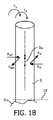
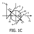
図1A〜図1Cは、それぞれ、従来技術によるシェーバー等のパーソナルケア装置によって毛(hair)を切断する際の側面図、概略正面図、及び上面図を示す。
このようなパーソナルケア装置は、第1の切刃2を有する内切断部材1と、第2の切刃4を有する外切断部材3とを少なくとも含む。人の皮膚6から延びる毛5を切断する場合に、この毛は、第1の接触位置7で第1の切刃2に接触し、第2の接触位置8で第2の切刃4に接触する。外切断部材3の丸みを帯びた形状によって、第2の接触位置8は、外切断部材3の内面9から距離Hに位置することになる。距離Sは、第1の切刃2と外切断部材3の内面9との間の距離であり、一方距離SWは、第1及び第2の接触位置7,8の間の有効切断ギャップであり、ここでSW=S+Hである。内切断部材1は、矢印P1で示される方向に外切断部材3に対して移動可能である。第1及び第2の切刃2,4は、移動方向に対してせん断角A1,A2で延びる。有効切断ギャップSWは、内切断部材1の形状によって毛を切断する際に変動し、矢印P1で示される方向での毛5に対する切刃2,4の位置に依存する。距離SWは、毛の前半部(first half)を切断する際に最大となる。
In the drawings, like reference numbers indicate like elements.
1A to 1C show a side view, a schematic front view, and a top view, respectively, when a hair is cut by a personal care device such as a shaver according to the prior art.
Such a personal care device includes at least an inner cutting member 1 having a
毛5を切断するときに、力Fm,Flが、内切断部材1及び外切断部材3によって毛に及ぼされる。せん断角A1,A2によって、力Fm,Flは、力FyM,FxM,FxL,FyLを生じさせる。力FxMが、力FxLよりも、皮膚6に対して実質的に平行に延びる仮想皮膚面10からより大きな距離に位置するので、力FxL,FxMによって、トルクTxが生じる。この距離の差は、距離SWである。このトルクTxによって、第1の切刃2は、第2の切刃4から離れる方向に押される。第1及び第2の切刃2,4の間の距離を一定に維持するために、力FxM及びFyMに対して垂直に延びる力FzMを、内切断部材2に加える必要がある。この力FzMによって、磨耗や発熱が生じる。力FyM,FyLによって、トルクTyも生じる。このトルクTyは、内切断部材2の軸受によって受け流される。
従来技術による上述したパーソナルケア装置では、有効切断ギャップSWは、ゼロより大きい。
When cutting the
In the above-described personal care device according to the prior art, the effective cutting gap SW is greater than zero.
本発明に係るパーソナルケア装置の場合には、以下で示すように、有効切断ギャップSWはゼロ以下であり、実際には、負となる。これは、毛を切断するときに、毛5に対して内部の第1の切刃2上の第1の接触位置7は、外部の第2の切刃4上の第2の接触位置8よりも仮想皮膚面10に対してより近くに位置することを意味する。第1及び第2の接触位置7,8の相対位置によって、トルクTxは、従来技術の装置のように第1の切刃2を押し出すのではなく、第1の切刃2を第2の切刃4に向けて押す。
In the case of the personal care device according to the present invention, as shown below, the effective cutting gap SW is equal to or less than zero and is actually negative. This is because when the hair is cut, the first contact position 7 on the inner
図2〜図4は、本発明に係るパーソナルケア装置の第1の実施形態の切断装置21の様々な図を示す。切断装置21を有するパーソナルケア装置は、当該技術分野において周知であり、さらに詳細には説明しない。パーソナルケア装置は、シェーバー、トリマー、グルーミング装置又は他の種類の切断装置であってもよい。このようなパーソナルケア装置の切断装置の全ては、内切断部材と外切断部材とを有しており、内切断部材は、外切断部材に対して回転可能な又は並進可能のいずれかである。
2 to 4 show various views of the cutting
切断装置21は、内切断部材22と外切断部材23とを有する。外切断部材23は、中心シャフト24と、この中心シャフト24に対して垂直に延びるディスク25とを有する。中心シャフト24は、中心軸26に対して平行に延びる。ディスク25は、中心軸26に対して垂直に延びる本体部27を含む。外周縁の近くに、ディスク25は、多数の歯29を有する屈曲部28を含む。歯29は、アキシャル方向に、本体部27から所定の距離に配置される。図3に確認されるように、各歯29は、第1及び第2の側面30,31を有しており、これらの側面は、湾曲部32を介して互いに接続される。互いに隣接して配置された歯29が、湾曲部33を介して互いに接続される。歯29同士の間に、外切断部材23の複数のU字形状の毛進入開口部34が配置される。
The cutting
内切断部材22は、中空シャフト35と、この中空シャフト35に対して垂直に延びるディスク36だけでなく、このディスク36に対して平行に延びるギヤ36’とを有する。中空シャフト35は、外切断部材22のシャフト24と同軸に延びる。ギヤ36’は、矢印P2で示される方向に、中心軸26を中心にして内切断部材22を回転させるための他の駆動手段に接続される。このような駆動手段は、当技術分野で周知であり、更なる説明を省略する。ディスク36は、中心軸26に対して垂直に延びる本体部37を含む。外周縁の近くに、ディスク36は、内切断部材22の複数の切断要素を形成するような多数の歯39を有する屈曲部38を含む。歯39は、歯29の近くに配置される。
各歯39の第1の面40が、第1の切刃50を形成し、この第1の切刃50は、第2の切刃51を形成する歯29の第1の側面30と協働する。
The
The
図3に明確に確認されるように、第1の切刃50は、半径方向に延びるライン46とでせん断角A3を囲む一方、第2の切刃51は、ライン46とでせん断角A4を囲む。両方のせん断角A3,A4は、ゼロ度よりも大きい。
図4に確認されるように、内切断部材22及び外切断部材23の歯29,39は、仮想平面10に対して傾斜され、その仮想平面10とで傾斜角A5を囲む。仮想平面10は、中心軸26に対して垂直に延びており、且つ内切断部材22から離れる方向に面する、外切断部材23の側に位置する。
パーソナルケア装置を作動しているときに、内切断部材22は、人の皮膚表面に対して実質的に垂直に延びるような中心軸26を中心に回転する。毛は、毛進入開口部34内に捕獲される。内切断部材22の更なる移動により、捕獲された毛は、第1及び第2の切刃50,51が協働することによって切断される。
As clearly seen in FIG. 3, the first cutting edge 50 surrounds the shear angle A <b> 3 with a
As can be seen in FIG. 4, the
When operating the personal care device, the
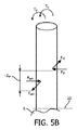
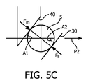
図5A〜図5Cは、第1及び第2の切刃50,51によって切断される毛5を概略的に示しており、第1及び第2の切刃50,51は、矢印P2で示される方向に対してせん断角A1,A2で延びており、皮膚表面及び仮想皮膚面10に対して傾斜角A5で傾斜する。
毛5を切断するときに、毛5は、第1の接触位置52で第1の切刃50に接触し、第2の接触位置53で第2の切刃51に接触する。力FyM,FxM,FxL,FyLが、切刃50,51によって毛5に及ぼされる。角度A1,A2及びA5によって、内切断部材22の第1の切刃50によって及ぼされる力FxM,FyMは、外切断部材23の第2の切刃51によって及ぼされる力FxL,FyLよりも、仮想皮膚面10からより小さい距離に位置する。この距離の差は、−SWの距離である。力FxM,FxLによって、トルクTxが生じる。トルクTxの方向は、図1に示されるトルクとは反対側の方向である。トルクTxによって、第1の切刃50は、従来技術の装置のように第2の切刃51から離れる方向に押されるが、第2の切刃51に向けて押されることはない。第1及び第2の切刃50,51の間の距離Sを一定に維持するために、力FxM,FyMに対して垂直な方向に内切断部材22に加える力は、全く又は殆ど必要ない。そのような力を加える必要がほぼ無いので、摩耗や発熱もほぼ発生しない。力FyM、FyLによって、トルクTyが生じる。このトルクTyは、内切断部材2の軸受によって受け流される。
5A to 5C schematically show the
When the
本発明に係るパーソナルケア装置の第1の実施形態の切断装置21では、内切断部材22の少なくとも1つの第1の切刃50と協働する第2の切刃51を有するような外切断部材23の全ての毛進入開口部34について、内切断部材22の第1の切刃50によって毛5に及ぼされる力が、外切断部材23の第2の切刃51により毛5に及ぼされる力よりも、仮想皮膚面10からより小さい距離に位置していることに留意されたい。毛切断力を受けた状況下で内切断部材22が外切断部材23から離れる方向に押されるのを防止し且つ内切断部材22及び外切断部材23を互いに向けて押す例えばばね力等の必要な釣合力の使用を止めるために、外切断部材23の全ての毛進入開口部34について、必ずしも内切断部材22の第1の切刃50によって毛5に及ぼされる力を、外切断部材23の第2の切刃51によって及ぼされる力よりも、仮想皮膚面10からより小さい距離に位置する必要はない。本発明によれば、内切断部材22の少なくとも1つの第1の切刃50と協働する第2の切刃51を有するような外切断部材23の全ての毛進入開口部34の少なくとも60%(パーセント)の割合について、せん断角A3,A4と、内切断部材22及び外切断部材23の傾斜角A5とは、毛進入開口部34内の切断位置に位置しており且つ仮想皮膚面10に対して垂直に延びる毛5を切断する開始位置において、内切断部材22の第1の切刃50が、第1の接触位置で毛5と接触しており、外切断部材23の第2の切刃51が、第2の接触位置で毛5と接触するように選択すべきであり、ここで第1の接触位置は、第2の接触位置よりも仮想皮膚面10により近い位置にある。その割合が少なくとも60%である場合には、内切断部材22の第1の切刃50と外切断部材23の第2の切刃51とに及ぼされるような全ての毛切断力の平均は、内切断部材22と外切断部材23とを互いに向けさせるような力である。より好ましくは、その割合は、少なくとも80%である。
In the
図6は、本発明に係るパーソナルケア装置の切断装置61の更なる実施形態の概略図を示し、この切断装置は、第1の切刃63を有する内切断部材62と、第2の切刃65を有する外切断部材64とを含む。内切断部材62は、外部切断部材64に対して中心軸26(図6には図示せず)を中心に回転可能である。図6では、1つのみの第1の切刃63と1つのみの第2の切刃65とが、示されている。上述した切断装置21と同様に、切断装置61は、多数の切刃63,65を含む。第2の切刃65は、第1の刃部66と、この第1の刃部66に接続された第2の刃部67とを含む。第1の刃部66は、第2の刃部67よりも中心軸26の近くに位置する。第1の刃部66は、半径方向に延びるライン46とでせん断角A6を囲むとともに、矢印P2で示される方向にライン46から延びる一方、第2の刃部67は、半径方向に延びるライン46とでせん断角A7を囲むとともに、矢印P2で示される方向とは反対方向にライン46から延びる。毛5を切断するときに、第2の刃部67と接触している毛5は、中心軸26に向けて押され、第1の刃部66で切断される。図6に示されるような切断装置61の実施形態では、第1の切刃63の第1の傾斜角、第2の切刃65の第2の傾斜角、第1の切刃63の第1のせん断角、及び第2の切刃65の第1の刃部66のせん断角A6は、毛5が第1の切刃63と第2の切刃65の第1の刃部66とによって切断される開始位置にあるときに、毛5と第1の切刃63との間の第1の接触位置が、毛5と第2の切刃65の第1の刃部66との間の第2の接触位置よりも仮想皮膚面に対してより近くなるように選択される。第1の刃部66は、中心軸26に対してより近くに配置されるので、パーソナルケア装置に対する切断力の影響は、さらに低減される。
FIG. 6 shows a schematic view of a further embodiment of a
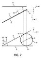
図7は、第1の切刃71と第2の切刃72とによって、150マイクロメートルの直径Dの毛70を切断する原理を概略的に示す。毛の平均直径は、150マイクロメートルである。毛を切断する原理は、異なる直径の毛にも当てはまる。第1の切刃71は、第2の切刃72に対してY方向に移動可能である。XY方向に延びる仮想平面73は、ユーザの皮膚表面に対して平行に延びるとともに、Z方向に対して垂直に延びる。
第1の切刃71は、移動方向に対して90度のせん断角A8で且つ仮想面73に対して傾斜角A9で延びる。
第2の切刃72は、移動方向に対してせん断角A10で且つ仮想平面73に対して傾斜角A9でも延びる。
FIG. 7 schematically shows the principle of cutting the
The
The
毛70を切断する開始位置において、第1の切刃71は、第1の接触位置74で毛70に接触する一方、第2の切刃72は、第2の接触位置75で毛70に接触する。角度A8,A9,A10によって、第1の接触位置74は、第2の接触位置75よりも仮想皮膚面73に対してより近くに配置され、上述したようにトルクTxがもたらされ、第2の切刃72に向けて第1の切刃71に力を加える。
第1及び第2の切刃71,72の傾斜角A9は、好ましくは約5〜約30°であり、より好ましくは約15°である。
角度A8,A9,A10の大きさは、第1の接触位置74が第2の接触位置75よりも仮想皮膚面73に対してより近くに配置された場合に、決定される。
At the starting position for cutting the
The inclination angle A9 of the first and second cutting edges 71 and 72 is preferably about 5 to about 30 °, more preferably about 15 °.
The magnitudes of the angles A8, A9, and A10 are determined when the
図8の符号A〜Rは、仮想平面7に対する第1及び第2の切刃71,72の様々な相対位置を示し、図8の符号A及び符号Kは、X,Z平面における第1及び第2の切刃71,72を示し、第1及び第2の切刃71,72の間の距離は、両方の切刃を表示するために誇張されている。実際には、Z方向の距離は、可能な限り小さい。図8の符号B〜符号H及び図8の符号L〜符号Rは、X,Y平面における第1及び第2の切刃71,72を示す。Y方向は、移動方向を示す。この移動は、直線往復運動又は回転運動とすることができる。回転運動の場合には、X方向が半径方向を示し、Y方向が、接線方向を示す一方で、Z方向は、軸方向を示す。
図8の符号Aに確認されるように、切刃71,72の左側Lは、右側Rよりも仮想皮膚面73からさらに離れて位置している。
Reference signs A to R in FIG. 8 indicate various relative positions of the first and second cutting edges 71 and 72 with respect to the virtual plane 7. Reference signs A and K in FIG. 8 indicate first and second positions in the X and Z planes. The second cutting edges 71, 72 are shown, and the distance between the first and second cutting edges 71, 72 is exaggerated to display both cutting edges. In practice, the distance in the Z direction is as small as possible. Reference signs B to H in FIG. 8 and reference signs L to R in FIG. 8 indicate the first and second cutting edges 71 and 72 in the X and Y planes. The Y direction indicates the moving direction. This movement can be a linear reciprocating motion or a rotational motion. In the case of rotational movement, the X direction indicates the radial direction, the Y direction indicates the tangential direction, while the Z direction indicates the axial direction.
As can be seen from the symbol A in FIG. 8, the left side L of the cutting edges 71 and 72 is located further away from the
図8の符号B〜符号Dでは、切刃71,72は、交点76で交差し、この交点76は、切刃71,72の左側Lに位置している。これらの3つの実施形態について、X方向に対する第1及び第2の切刃71,72のせん断角B1,B2は、B2の絶対値がB1の絶対値よりも大きくなるようにされる。
図8の符号Eでは、せん断角A8=A10である。
図8の符号F〜符号Hでは、切刃71,72は、交点76で交差し、この交点76は、切刃71,72の右側Rに位置している。これら3つの実施形態について、X方向に対する第1及び第2の切刃71,72のせん断角B3,B4は、B4の絶対値が、B3の絶対値よりも小さくなるようにされる。
これら全ての実施形態では、第1の接触位置74は、第2の接触位置75よりも仮想皮膚面73に対してより近くに配置される。
図に確認されるように、図8の符号K〜符号Rは、図8の符号A〜符号Hの鏡像関係にあり、作動原理は同じである。
8, the cutting edges 71 and 72 intersect at an intersection point 76, and this intersection point 76 is located on the left side L of the cutting edges 71 and 72. For these three embodiments, the shear angles B1, B2 of the first and second cutting edges 71, 72 with respect to the X direction are such that the absolute value of B2 is greater than the absolute value of B1.
In the symbol E in FIG. 8, the shear angle A8 = A10.
8, the cutting edges 71 and 72 intersect at an intersection point 76, and this intersection point 76 is located on the right side R of the cutting edges 71 and 72. For these three embodiments, the shear angles B3, B4 of the first and second cutting edges 71, 72 with respect to the X direction are such that the absolute value of B4 is smaller than the absolute value of B3.
In all these embodiments, the
As can be seen from the figure, reference symbols K to R in FIG. 8 are mirror images of reference symbols A to H in FIG. 8, and the operating principle is the same.
当業者は、本発明が好適な実施形態に限定されるものではないことを理解するであろう。開示された実施例に対する他の変形形態は、図面、明細書の開示、及び添付の特許請求の範囲の検討から請求項に記載された発明を実施する際に当業者によって理解され且つ行うことができる。
請求項において、「備える、有する、含む(comprising)」という用語は、他の要素又はステップを排除するものではなく、不定冠詞「1つの(a, an)」は、複数を除外するものではない。特定の手段が互いに異なる従属請求項に記載されているという単なる事実は、これらの手段の組合せが有利に使用できないことを示すものではない。
請求項における任意の参照符号は、特許請求の範囲を限定するものとして解釈すべきではない。
Those skilled in the art will appreciate that the present invention is not limited to the preferred embodiments. Other variations to the disclosed embodiments can be understood and made by those skilled in the art in practicing the claimed invention from a study of the drawings, the disclosure of the specification, and the appended claims. it can.
In the claims, the term “comprising” does not exclude other elements or steps, and the indefinite article “a, an” does not exclude a plurality. . The mere fact that certain measures are recited in mutually different dependent claims does not indicate that a combination of these measured cannot be used to advantage.
Any reference signs in the claims should not be construed as limiting the scope.
1 部材
2 切刃
3 部材
4 切刃
5 毛
6 皮膚
7 位置
8 位置
9 面
10 仮想皮膚面
21 切断装置
22 内部切断部材
23 外部切断部材
24 シャフト
25 ディスク
26 中心軸
27 本体部
29 歯
30 側面
31 側面
32 湾曲部
33 湾曲部
34 毛進入開口部
35 シャフト
36 ディスク
36’ ギヤ
37 本体部
38 屈曲部
39 歯
40 側面
46 ライン
50 第1の切刃
51 第2の切刃
52 位置
53 位置
61 装置
62 部材
63 切刃
64 部材
65 切刃
66 第1の刃部
67 第2の刃部
70 毛
71 切刃
72 切刃
73 面
74 第1の接触位置
75 第2の接触位置
76 交点
A1 角度
A2 角度
A4 角度
A3 角度
A5 角度
A7 角度
A8 角度
A9 角度
A10 角度
B1 角度
B2 角度
B3 角度
B4 角度
D 直径
Fm 力
Fl 力
FyM 力
FxM 力
FxL 力
FyL 力
H 距離
L 左側
P1 矢印
P2 矢印
R 右側
S 距離
Tx トルク
T トルク
SW ギャップ
DESCRIPTION OF SYMBOLS 1
Claims (9)
各切断装置は、外切断部材と、該外切断部材に対して少なくとも1つの移動方向に移動可能な内切断部材とを含み、該内切断部材は、各々が第1の切刃を有する複数の切断要素を含み、
仮想皮膚面における第1の切刃の投影が、前記内切断部材から離れる方向で面する前記外切断部材の側に位置し、且つ前記移動方向と平行に延びるとともに、前記切断装置が皮膚表面に対して作動位置にある場合に、該皮膚表面に対して平行に延びており、前記仮想皮膚面における第1の切刃の投影は、前記移動方向とで少なくとも第1のせん断角を囲み、
前記外切断部材は、各々が少なくとも1つの第1の切刃と協働する第2の切刃を有するような複数の毛進入開口部を含み、
前記仮想皮膚面における第2の切刃の投影が、前記移動方向とで少なくとも第2のせん断角を囲み、
前記内切断部材の少なくとも1つの第1の切刃と協働する第2の切刃を有するような前記外切断部材の全ての前記毛進入開口部のうちの少なくとも60パーセントについて、前記移動方向に対して垂直に延びる平面における第1及び第2の切刃の投影は、それぞれ、前記切断装置の仮想皮膚面とで第1の傾斜角及び第2の傾斜角を囲み、
第1及び第2の傾斜角と第1及び第2のせん断角とは、前記毛進入開口部の切断位置に位置しており且つ前記仮想皮膚面に対して垂直に延びる150ミクロンの直径の仮想円筒毛を切断する少なくとも開始位置で、第1の切刃は、第1の接触位置で前記仮想円筒毛に接触し、且つ第2の切刃は、第2の接触位置で前記仮想円筒毛に接触するように選択され、
第1の接触位置は、第2の接触位置よりも前記仮想皮膚面に対してより近くにある、
パーソナルケア装置。 A path Sonarukea apparatus in which at least one cutting device is provided,
Each cutting device includes an outer cutting member and an inner cutting member movable in at least one moving direction with respect to the outer cutting member, and the inner cutting member includes a plurality of cutting blades each having a first cutting edge. Including cutting elements,
Projection of the first cutting edge in the virtual skin surface is positioned on the side of the outer cutting member facing in a direction away from the inner cutting member, and extends parallel to the moving direction, to the cutting device the skin surface Extending in parallel to the skin surface when in the operating position, the projection of the first cutting edge on the virtual skin surface surrounds at least a first shear angle with the direction of movement,
The outer cutting member includes a plurality of hair entry openings each having a second cutting edge cooperating with at least one first cutting edge;
The projection of the second cutting edge on the virtual skin surface surrounds at least a second shear angle with the direction of movement;
For at least 60 percent of all the hair entry opening of the outer cutting member, such as having at least one first second cutting edge for cooperation with the cutting edge of the inner cutting member, said moving Projections of the first and second cutting edges in a plane extending perpendicular to the direction enclose a first inclination angle and a second inclination angle respectively with the virtual skin surface of the cutting device;
First and second tilt angle to the first and second shear angle, the hair entry located at the cutting position of the opening and the diameter of 1 50 micron Ru extend perpendicular to the imaginary surface of the skin At least a starting position for cutting the virtual cylindrical hair, the first cutting blade contacts the virtual cylindrical hair at the first contact position, and the second cutting blade contacts the virtual cylinder at the second contact position. Selected to contact the hair,
First contact position, near Ru closer to the virtual skin surface than the second contact position,
Personal care device.
請求項1に記載のパーソナルケア装置。 The percentage of all the hair entry openings of the outer cutting member as having a second cutting edge cooperating with at least one first cutting edge of the inner cutting member is at least 80;
The personal care device according to claim 1.
請求項1に記載のパーソナルケア装置。 The percentage of all the hair entry openings in the outer cutting member as having a second cutting edge cooperating with at least one first cutting edge of the inner cutting member is 100;
The personal care device according to claim 1.
請求項1,2又は3に記載のパーソナルケア装置。 For at least 60 percent of all the hair entry opening of the outer cutting member, such as having at least one first second cutting edge for cooperation with the cutting edge of said cutting member, before listen entry opening In each cutting position of the virtual cylindrical hair in the section, the first contact position is closer to the virtual skin surface at the start position than the second contact position, and the virtual cylindrical hair is Extending perpendicular to the skin surface,
The personal care device according to claim 1, 2 or 3.
請求項1乃至4のいずれか一項に記載の前記パーソナルケア装置。 The inner cutting member is rotatable with respect to the outer cutting member about a central axis of the cutting device, and the virtual skin surface extends perpendicularly to the central axis.
The personal care device according to any one of claims 1 to 4.
前記毛進入開口部の第1の端部の近くで、第2の切刃と前記反対側の切刃とは、湾曲部によって互いに接続される一方、該湾曲部から離れる側の前記毛進入開口部の第2の端部の近くで、前記毛進入開口部は、開いている、
請求項1乃至5のいずれか一項に記載のパーソナルケア装置。 At least one of the bristle entry opening, the boundary is delimited by the opposite side of the cutting edge and the second cutting edge,
Wherein near the first end of the hair entry apertures, and the cutting edge of the second cutting edge and the opposite side, while that will be connected to one another by a curved portion, the bristles entry opening on the side away from the curved portion Near the second end of the section, the hair entry opening is open,
The personal care device according to any one of claims 1 to 5.
前記毛進入開口部の第1の端部の近くで、第2の切刃と前記反対側の切刃は、湾曲部によって互いに接続される一方、該湾曲部から離れる側の前記毛進入開口部の第2の端部の近くで、前記毛進入開口部は、開いており、
第2の切刃は、第1の刃部と、第1の刃部に接続された第2の刃部とを含み、
第1の刃部は、第2の刃部よりも中心軸に対してより近くに配置され、
第1の刃部と前記移動方向との間で囲まれたせん断角は、第2の刃部と前記移動方向とによって囲まれたせん断角よりも小さく、
第1及び第2の傾斜角、第1のせん断角、及び第1の刃部のせん断角は、第1の切刃と、第2の切刃の第1の刃部との間の位置における前記仮想円筒毛を切断する開始位置において、第1の接触位置が、第2の接触位置よりも前記仮想皮膚面に対してより近くなるように選択される、
請求項1,2,3又は5に記載のパーソナルケア装置。 At least one of the bristle entry opening, the boundary is delimited by the opposite side of the cutting edge and the second cutting edge,
Near the first end of the hair entry opening, the second cutting edge and the opposite cutting edge are connected to each other by a curved part, while the hair entry opening on the side away from the curved part Near the second end of the hair entry opening is open,
The second cutting blade includes a first blade portion and a second blade portion connected to the first blade portion,
The first blade portion is disposed closer to the central axis than the second blade portion,
The shear angle surrounded between the first blade portion and the moving direction is smaller than the shear angle surrounded by the second blade portion and the moving direction,
The first and second inclination angles, the first shear angle, and the shear angle of the first blade portion are at positions between the first cutting edge and the first blade portion of the second cutting edge. At the start position for cutting the virtual cylindrical hair, the first contact position is selected to be closer to the virtual skin surface than the second contact position.
The personal care device according to claim 1, 2, 3 or 5.
請求項1乃至7のいずれか一項に記載のパーソナルケア装置。 The first and second tilt angles are between 5-30 °;
The personal care device according to any one of claims 1 to 7.
Applications Claiming Priority (3)
| Application Number | Priority Date | Filing Date | Title |
|---|---|---|---|
| EP13177931 | 2013-07-25 | ||
| EP13177931.6 | 2013-07-25 | ||
| PCT/EP2014/065212 WO2015010979A1 (en) | 2013-07-25 | 2014-07-16 | A personal care device as well as a cutting unit for such a personal care device |
Publications (3)
| Publication Number | Publication Date |
|---|---|
| JP2016525001A JP2016525001A (en) | 2016-08-22 |
| JP2016525001A5 JP2016525001A5 (en) | 2018-02-15 |
| JP6325671B2 true JP6325671B2 (en) | 2018-05-16 |
Family
ID=48875569
Family Applications (1)
| Application Number | Title | Priority Date | Filing Date |
|---|---|---|---|
| JP2016528428A Active JP6325671B2 (en) | 2013-07-25 | 2014-07-16 | Personal care device and cutting device for such a personal care device |
Country Status (6)
| Country | Link |
|---|---|
| US (1) | US9956697B2 (en) |
| EP (1) | EP3024624B1 (en) |
| JP (1) | JP6325671B2 (en) |
| CN (1) | CN105408072B (en) |
| RU (1) | RU2693401C2 (en) |
| WO (1) | WO2015010979A1 (en) |
Families Citing this family (6)
| Publication number | Priority date | Publication date | Assignee | Title |
|---|---|---|---|---|
| CN105408072B (en) * | 2013-07-25 | 2018-05-18 | 皇家飞利浦有限公司 | Personal care device and the cutter unit for this personal care device |
| EP3103600A1 (en) | 2015-06-08 | 2016-12-14 | BaByliss Faco sprl | Beard trimmer with one or more rotating heads surrounded by combs with particular geometry and equipped with a protection position for the comb |
| US20170217030A1 (en) * | 2016-02-02 | 2017-08-03 | Izumi Products Company | Rotary electric shaver and method of manufacturing outer blade of rotary electric shaver |
| JP6595727B2 (en) * | 2016-05-31 | 2019-10-23 | コーニンクレッカ フィリップス エヌ ヴェ | Attachment for personal care devices |
| CN107309915A (en) * | 2017-07-19 | 2017-11-03 | 吴让攀 | Rotary shaver head |
| US11737395B2 (en) * | 2019-05-22 | 2023-08-29 | LPF Robotics, LLC | Apparatuses and methods for removing plant material |
Family Cites Families (20)
| Publication number | Priority date | Publication date | Assignee | Title |
|---|---|---|---|---|
| HU146204A (en) * | ||||
| US2261275A (en) * | 1938-06-22 | 1941-11-04 | Walter J Pasinski | Electric razor |
| NL59158C (en) | 1942-01-13 | 1900-01-01 | ||
| US2677884A (en) | 1948-12-29 | 1954-05-11 | Richard & Ammann S A | Rotary razor shear head |
| BE631111A (en) | 1962-04-16 | |||
| US3225440A (en) * | 1963-09-19 | 1965-12-28 | Owens Neal | Electric shaver having angled blades adapted to be inserted in corresponding angled slots in a blade supporting member |
| JPS53391Y2 (en) * | 1972-11-09 | 1978-01-09 | ||
| JPS5314974B2 (en) * | 1972-08-30 | 1978-05-22 | ||
| DE2342678A1 (en) * | 1972-08-30 | 1974-03-21 | Matsushita Electric Works Ltd | SHEARING HEAD FOR AN ELECTRIC DRY SHAVER |
| NL8302234A (en) * | 1983-06-23 | 1985-01-16 | Philips Nv | SHAVER. |
| NL8400887A (en) * | 1984-03-21 | 1985-10-16 | Philips Nv | SHAVER. |
| JPS647293U (en) * | 1987-06-27 | 1989-01-17 | ||
| NL8902807A (en) * | 1989-11-14 | 1991-06-03 | Philips Nv | SHAVER. |
| BE1007711A3 (en) * | 1993-11-05 | 1995-10-03 | Koninkl Philips Electronics Nv | Shaver. |
| US6769179B2 (en) | 2000-07-06 | 2004-08-03 | Teizoh Satoh | Shaver |
| US20050198824A1 (en) | 2004-03-12 | 2005-09-15 | White Dennis J. | Rotary hair trimmer |
| JP2006218219A (en) | 2005-02-14 | 2006-08-24 | Izumi Products Co | Rotary type electric razor |
| JP5649213B2 (en) * | 2010-11-08 | 2015-01-07 | 株式会社泉精器製作所 | Electric razor outer blade and inner blade manufacturing method |
| CN102366962B (en) * | 2011-10-18 | 2014-11-12 | 上海奔腾电工有限公司 | Tool bit for rotary electric shaver |
| CN105408072B (en) * | 2013-07-25 | 2018-05-18 | 皇家飞利浦有限公司 | Personal care device and the cutter unit for this personal care device |
-
2014
- 2014-07-16 CN CN201480041846.8A patent/CN105408072B/en active Active
- 2014-07-16 JP JP2016528428A patent/JP6325671B2/en active Active
- 2014-07-16 US US14/904,976 patent/US9956697B2/en active Active
- 2014-07-16 EP EP14739450.6A patent/EP3024624B1/en active Active
- 2014-07-16 RU RU2016106107A patent/RU2693401C2/en active
- 2014-07-16 WO PCT/EP2014/065212 patent/WO2015010979A1/en active Application Filing
Also Published As
| Publication number | Publication date |
|---|---|
| WO2015010979A1 (en) | 2015-01-29 |
| EP3024624A1 (en) | 2016-06-01 |
| RU2693401C2 (en) | 2019-07-02 |
| EP3024624B1 (en) | 2018-07-11 |
| US9956697B2 (en) | 2018-05-01 |
| CN105408072B (en) | 2018-05-18 |
| JP2016525001A (en) | 2016-08-22 |
| CN105408072A (en) | 2016-03-16 |
| US20160158947A1 (en) | 2016-06-09 |
| RU2016106107A3 (en) | 2018-06-26 |
| RU2016106107A (en) | 2017-08-30 |
Similar Documents
| Publication | Publication Date | Title |
|---|---|---|
| JP6325671B2 (en) | Personal care device and cutting device for such a personal care device | |
| JP6356341B2 (en) | Shaving device for body hair | |
| JP6072820B2 (en) | Improved shaving head with doming control | |
| JP6525298B1 (en) | Rotary shaver and its inner blade | |
| JP6030763B2 (en) | Hair clipping device | |
| JP2015506222A (en) | Rotary shaving unit | |
| JP2018161480A5 (en) | ||
| JP2015211743A (en) | scissors | |
| JP2016525001A5 (en) | ||
| JP2016514509A (en) | Shaving device and cutting unit for the shaving device | |
| TWI290079B (en) | Knife sharpener | |
| JP3198628U (en) | Hair removal apparatus having apparatus for preparing skin | |
| JP6262234B2 (en) | Hair clipping device | |
| US1633063A (en) | Hair-cutting machine | |
| JP7043627B2 (en) | Hair cutting unit with hair guide element with thickness profile | |
| US2222308A (en) | Safety razor | |
| JP3896506B2 (en) | Electric razor | |
| US20050198824A1 (en) | Rotary hair trimmer | |
| WO2015128181A1 (en) | A personal care device | |
| CN109382852B (en) | Cutter and hair trimmer of sandwich type structure | |
| JP4310094B2 (en) | Hair salon / beauty salon | |
| WO2013149497A2 (en) | Electric shaver head device | |
| JP2020028500A (en) | Rotary shaver and inner blade therefor | |
| JPS6014892A (en) | Shaver | |
| JP2003290571A (en) | Scissors |
Legal Events
| Date | Code | Title | Description |
|---|---|---|---|
| A621 | Written request for application examination |
Free format text: JAPANESE INTERMEDIATE CODE: A621 Effective date: 20170713 |
|
| A521 | Request for written amendment filed |
Free format text: JAPANESE INTERMEDIATE CODE: A523 Effective date: 20171227 |
|
| A871 | Explanation of circumstances concerning accelerated examination |
Free format text: JAPANESE INTERMEDIATE CODE: A871 Effective date: 20171227 |
|
| A975 | Report on accelerated examination |
Free format text: JAPANESE INTERMEDIATE CODE: A971005 Effective date: 20180124 |
|
| TRDD | Decision of grant or rejection written | ||
| A01 | Written decision to grant a patent or to grant a registration (utility model) |
Free format text: JAPANESE INTERMEDIATE CODE: A01 Effective date: 20180320 |
|
| A61 | First payment of annual fees (during grant procedure) |
Free format text: JAPANESE INTERMEDIATE CODE: A61 Effective date: 20180412 |
|
| R150 | Certificate of patent or registration of utility model |
Ref document number: 6325671 Country of ref document: JP Free format text: JAPANESE INTERMEDIATE CODE: R150 |
|
| R250 | Receipt of annual fees |
Free format text: JAPANESE INTERMEDIATE CODE: R250 |
|
| R250 | Receipt of annual fees |
Free format text: JAPANESE INTERMEDIATE CODE: R250 |
|
| R250 | Receipt of annual fees |
Free format text: JAPANESE INTERMEDIATE CODE: R250 |