JP6325076B2 - Screen assembly - Google Patents
Screen assembly Download PDFInfo
- Publication number
- JP6325076B2 JP6325076B2 JP2016502685A JP2016502685A JP6325076B2 JP 6325076 B2 JP6325076 B2 JP 6325076B2 JP 2016502685 A JP2016502685 A JP 2016502685A JP 2016502685 A JP2016502685 A JP 2016502685A JP 6325076 B2 JP6325076 B2 JP 6325076B2
- Authority
- JP
- Japan
- Prior art keywords
- screen assembly
- screen
- retainer
- edge
- core
- Prior art date
- Legal status (The legal status is an assumption and is not a legal conclusion. Google has not performed a legal analysis and makes no representation as to the accuracy of the status listed.)
- Active
Links
- 238000003780 insertion Methods 0.000 claims description 27
- 230000037431 insertion Effects 0.000 claims description 27
- 239000000853 adhesive Substances 0.000 claims description 5
- 230000001070 adhesive effect Effects 0.000 claims description 5
- 239000004744 fabric Substances 0.000 claims description 4
- 239000000463 material Substances 0.000 claims description 4
- 238000011282 treatment Methods 0.000 description 13
- 230000002093 peripheral effect Effects 0.000 description 4
- 230000000712 assembly Effects 0.000 description 3
- 238000000429 assembly Methods 0.000 description 3
- 230000008901 benefit Effects 0.000 description 3
- 229920005830 Polyurethane Foam Polymers 0.000 description 2
- 238000001125 extrusion Methods 0.000 description 2
- 239000003365 glass fiber Substances 0.000 description 2
- 239000011496 polyurethane foam Substances 0.000 description 2
- 238000003466 welding Methods 0.000 description 2
- RNFJDJUURJAICM-UHFFFAOYSA-N 2,2,4,4,6,6-hexaphenoxy-1,3,5-triaza-2$l^{5},4$l^{5},6$l^{5}-triphosphacyclohexa-1,3,5-triene Chemical compound N=1P(OC=2C=CC=CC=2)(OC=2C=CC=CC=2)=NP(OC=2C=CC=CC=2)(OC=2C=CC=CC=2)=NP=1(OC=1C=CC=CC=1)OC1=CC=CC=C1 RNFJDJUURJAICM-UHFFFAOYSA-N 0.000 description 1
- 241000544076 Whipplea modesta Species 0.000 description 1
- 230000004888 barrier function Effects 0.000 description 1
- 235000012438 extruded product Nutrition 0.000 description 1
- 239000000835 fiber Substances 0.000 description 1
- 239000011094 fiberboard Substances 0.000 description 1
- 239000000945 filler Substances 0.000 description 1
- 239000003063 flame retardant Substances 0.000 description 1
- 239000006260 foam Substances 0.000 description 1
- 238000001746 injection moulding Methods 0.000 description 1
- 239000003550 marker Substances 0.000 description 1
- 238000005192 partition Methods 0.000 description 1
- 230000000284 resting effect Effects 0.000 description 1
- 238000009958 sewing Methods 0.000 description 1
- 239000000758 substrate Substances 0.000 description 1
- 210000002105 tongue Anatomy 0.000 description 1
Images


Classifications
-
- E—FIXED CONSTRUCTIONS
- E06—DOORS, WINDOWS, SHUTTERS, OR ROLLER BLINDS IN GENERAL; LADDERS
- E06B—FIXED OR MOVABLE CLOSURES FOR OPENINGS IN BUILDINGS, VEHICLES, FENCES OR LIKE ENCLOSURES IN GENERAL, e.g. DOORS, WINDOWS, BLINDS, GATES
- E06B9/00—Screening or protective devices for wall or similar openings, with or without operating or securing mechanisms; Closures of similar construction
- E06B9/24—Screens or other constructions affording protection against light, especially against sunshine; Similar screens for privacy or appearance; Slat blinds
-
- A—HUMAN NECESSITIES
- A47—FURNITURE; DOMESTIC ARTICLES OR APPLIANCES; COFFEE MILLS; SPICE MILLS; SUCTION CLEANERS IN GENERAL
- A47B—TABLES; DESKS; OFFICE FURNITURE; CABINETS; DRAWERS; GENERAL DETAILS OF FURNITURE
- A47B21/00—Tables or desks for office equipment, e.g. typewriters, keyboards
- A47B21/04—Tables or desks for office equipment, e.g. typewriters, keyboards characterised by means for holding or fastening typewriters or computer equipment
-
- A—HUMAN NECESSITIES
- A47—FURNITURE; DOMESTIC ARTICLES OR APPLIANCES; COFFEE MILLS; SPICE MILLS; SUCTION CLEANERS IN GENERAL
- A47G—HOUSEHOLD OR TABLE EQUIPMENT
- A47G5/00—Screens; Draught-deflectors
-
- E—FIXED CONSTRUCTIONS
- E04—BUILDING
- E04B—GENERAL BUILDING CONSTRUCTIONS; WALLS, e.g. PARTITIONS; ROOFS; FLOORS; CEILINGS; INSULATION OR OTHER PROTECTION OF BUILDINGS
- E04B2/00—Walls, e.g. partitions, for buildings; Wall construction with regard to insulation; Connections specially adapted to walls
- E04B2/72—Non-load-bearing walls of elements of relatively thin form with respect to the thickness of the wall
-
- E—FIXED CONSTRUCTIONS
- E04—BUILDING
- E04B—GENERAL BUILDING CONSTRUCTIONS; WALLS, e.g. PARTITIONS; ROOFS; FLOORS; CEILINGS; INSULATION OR OTHER PROTECTION OF BUILDINGS
- E04B2/00—Walls, e.g. partitions, for buildings; Wall construction with regard to insulation; Connections specially adapted to walls
- E04B2/74—Removable non-load-bearing partitions; Partitions with a free upper edge
- E04B2/7407—Removable non-load-bearing partitions; Partitions with a free upper edge assembled using frames with infill panels or coverings only; made-up of panels and a support structure incorporating posts
- E04B2/7416—Removable non-load-bearing partitions; Partitions with a free upper edge assembled using frames with infill panels or coverings only; made-up of panels and a support structure incorporating posts with free upper edge, e.g. for use as office space dividers
- E04B2/7422—Removable non-load-bearing partitions; Partitions with a free upper edge assembled using frames with infill panels or coverings only; made-up of panels and a support structure incorporating posts with free upper edge, e.g. for use as office space dividers with separate framed panels without intermediary support posts
- E04B2/7425—Details of connection of panels
-
- A—HUMAN NECESSITIES
- A47—FURNITURE; DOMESTIC ARTICLES OR APPLIANCES; COFFEE MILLS; SPICE MILLS; SUCTION CLEANERS IN GENERAL
- A47B—TABLES; DESKS; OFFICE FURNITURE; CABINETS; DRAWERS; GENERAL DETAILS OF FURNITURE
- A47B83/00—Combinations comprising two or more pieces of furniture of different kinds
- A47B83/001—Office desks or work-stations combined with other pieces of furniture, e.g. work space management systems
- A47B2083/005—Office wall with desktop function
- A47B2083/006—Office wall with desktop function having an incorporated display screen
-
- A—HUMAN NECESSITIES
- A47—FURNITURE; DOMESTIC ARTICLES OR APPLIANCES; COFFEE MILLS; SPICE MILLS; SUCTION CLEANERS IN GENERAL
- A47B—TABLES; DESKS; OFFICE FURNITURE; CABINETS; DRAWERS; GENERAL DETAILS OF FURNITURE
- A47B2200/00—General construction of tables or desks
- A47B2200/0066—Workstations
- A47B2200/0079—Conference or video conference table
-
- A—HUMAN NECESSITIES
- A47—FURNITURE; DOMESTIC ARTICLES OR APPLIANCES; COFFEE MILLS; SPICE MILLS; SUCTION CLEANERS IN GENERAL
- A47B—TABLES; DESKS; OFFICE FURNITURE; CABINETS; DRAWERS; GENERAL DETAILS OF FURNITURE
- A47B2200/00—General construction of tables or desks
- A47B2200/12—Vanity or modesty panels
-
- E—FIXED CONSTRUCTIONS
- E04—BUILDING
- E04B—GENERAL BUILDING CONSTRUCTIONS; WALLS, e.g. PARTITIONS; ROOFS; FLOORS; CEILINGS; INSULATION OR OTHER PROTECTION OF BUILDINGS
- E04B2/00—Walls, e.g. partitions, for buildings; Wall construction with regard to insulation; Connections specially adapted to walls
- E04B2/74—Removable non-load-bearing partitions; Partitions with a free upper edge
- E04B2/7407—Removable non-load-bearing partitions; Partitions with a free upper edge assembled using frames with infill panels or coverings only; made-up of panels and a support structure incorporating posts
- E04B2/7416—Removable non-load-bearing partitions; Partitions with a free upper edge assembled using frames with infill panels or coverings only; made-up of panels and a support structure incorporating posts with free upper edge, e.g. for use as office space dividers
- E04B2/7422—Removable non-load-bearing partitions; Partitions with a free upper edge assembled using frames with infill panels or coverings only; made-up of panels and a support structure incorporating posts with free upper edge, e.g. for use as office space dividers with separate framed panels without intermediary support posts
- E04B2/7427—Removable non-load-bearing partitions; Partitions with a free upper edge assembled using frames with infill panels or coverings only; made-up of panels and a support structure incorporating posts with free upper edge, e.g. for use as office space dividers with separate framed panels without intermediary support posts with adjustable angular connection of panels
- E04B2/7429—Removable non-load-bearing partitions; Partitions with a free upper edge assembled using frames with infill panels or coverings only; made-up of panels and a support structure incorporating posts with free upper edge, e.g. for use as office space dividers with separate framed panels without intermediary support posts with adjustable angular connection of panels using flexible hinges
-
- E—FIXED CONSTRUCTIONS
- E04—BUILDING
- E04B—GENERAL BUILDING CONSTRUCTIONS; WALLS, e.g. PARTITIONS; ROOFS; FLOORS; CEILINGS; INSULATION OR OTHER PROTECTION OF BUILDINGS
- E04B2/00—Walls, e.g. partitions, for buildings; Wall construction with regard to insulation; Connections specially adapted to walls
- E04B2/74—Removable non-load-bearing partitions; Partitions with a free upper edge
- E04B2002/7479—Details of connection of flexible sheets to frame or posts
-
- E—FIXED CONSTRUCTIONS
- E04—BUILDING
- E04B—GENERAL BUILDING CONSTRUCTIONS; WALLS, e.g. PARTITIONS; ROOFS; FLOORS; CEILINGS; INSULATION OR OTHER PROTECTION OF BUILDINGS
- E04B2/00—Walls, e.g. partitions, for buildings; Wall construction with regard to insulation; Connections specially adapted to walls
- E04B2/74—Removable non-load-bearing partitions; Partitions with a free upper edge
- E04B2002/7483—Details of furniture, e.g. tables or shelves, associated with the partitions
-
- E—FIXED CONSTRUCTIONS
- E04—BUILDING
- E04B—GENERAL BUILDING CONSTRUCTIONS; WALLS, e.g. PARTITIONS; ROOFS; FLOORS; CEILINGS; INSULATION OR OTHER PROTECTION OF BUILDINGS
- E04B2/00—Walls, e.g. partitions, for buildings; Wall construction with regard to insulation; Connections specially adapted to walls
- E04B2/74—Removable non-load-bearing partitions; Partitions with a free upper edge
- E04B2002/749—Partitions with screw-type jacks
Description
(関連出願)
本出願は、2013年3月15日出願の米国仮特許出願番号第61/791,639号の利益を主張するものであり、その開示の全体が引用により本明細書に組み入れられる。
(Related application)
This application claims the benefit of US Provisional Patent Application No. 61 / 791,639, filed March 15, 2013, the entire disclosure of which is incorporated herein by reference.
(技術分野)
本出願は、スクリーン組立体、例えば、限定ではなく例として、オフィス環境で用いるためのスクリーン組立体に関する。
(Technical field)
The present application relates to a screen assembly, for example, by way of example and not limitation, a screen assembly for use in an office environment.
例えば、別々の作業空間を仕切るため、遮音壁の機能を果たすため、マーカーボード、タックボード、及びビデオスクリーンなどの種々の表示システムを提供するため、及び/又は、種々の作業空間のためのプライバシーを提供及び/又は高めるために、様々なオフィス環境においてスクリーンを使用することはよく知られている。多くの場合、そうしたスクリーンは、その片面又は両面が布地などのカバーで覆われており、そのことは、スクリーンの外観のカスタマイズ化を可能にし得る。しかしながら、そうしたカバーの装着は困難であり、種々のスプライン、キャップ、接着剤、又は他の外部装置の位置決め及び取り付けを要することがある。 For example, to partition different work spaces, to serve as a sound barrier, to provide various display systems such as marker boards, tack boards and video screens and / or to provide privacy for various work spaces It is well known to use screens in various office environments to provide and / or enhance. In many cases, such screens are covered on one or both sides with a cover such as a fabric, which may allow customization of the appearance of the screen. However, mounting such covers is difficult and may require positioning and mounting of various splines, caps, adhesives, or other external devices.
さらに、スクリーンは、完成した外観をスクリーンに与え、布地の縁部を覆う外周フレームを有するように構成されることが多い。そうしたフレームは、多くの場合、取り付けが困難であり、スクリーンの全重量を増大させるため、スクリーンの携帯性が低下し、又はデスク及び他の場所への取り付けに適さなくなる。 Furthermore, the screen is often configured to have a perimeter frame that gives the screen a finished appearance and covers the edges of the fabric. Such frames are often difficult to install and increase the overall weight of the screen, thus reducing the portability of the screen or making it unsuitable for mounting on desks and other locations.
簡単に述べると、1つの態様において、スクリーン組立体の1つの実施形態は、縁部、並びに第1及び第2の対向する側面を有するコアを含む。リテーナが、コアの縁部に結合され、コアから外方に延びる。リテーナは、それぞれの縁部部分を有し、口部を定める第1及び第2の弾性リムを含む。第1及び第2の弾性リムは、それらの間に内部キャビティを定める。第1及び第2の弾性リムは、それぞれの外面を定める。第1及び第2の弾性リムの縁部部分は、保持構成と挿入構成の間で互いに向かって及び互いから離れるように可動であり、第1及び第2のリムは、保持構成の方向に付勢される。第1及び第2のカバー部分はそれぞれ縁部を有し、第1のカバー部分は、コアの第1の側及び第1の弾性リムの外面の上に重なり、第2のカバー部分は、コアの第2の側及び第2の弾性リムの外面の上に重なる。第1及び第2のカバー部分は、該第1及び第2のリムの縁部部分の周りに巻き付き、口部を通して配置されるので、第1及び第2のカバー部分の縁部が内部キャビティ内に配置されるようになる。第1及び第2の弾性リムは、それらの間に第1及び第2のカバー部分を保持する。 Briefly, in one aspect, one embodiment of a screen assembly includes a core having an edge and first and second opposing sides. A retainer is coupled to the edge of the core and extends outward from the core. The retainer includes first and second elastic rims having respective edge portions and defining a mouth. The first and second elastic rims define an internal cavity between them. The first and second elastic rims define respective outer surfaces. The edge portions of the first and second elastic rims are movable toward and away from each other between the holding configuration and the insertion configuration, and the first and second rims are attached in the direction of the holding configuration. Be forced. The first and second cover portions each have an edge, the first cover portion overlies the first side of the core and the outer surface of the first elastic rim, and the second cover portion is the core Overlying the second side and the outer surface of the second elastic rim. The first and second cover portions wrap around the edge portions of the first and second rims and are disposed through the mouth so that the edges of the first and second cover portions are within the internal cavity. Will be placed in. The first and second elastic rims hold the first and second cover portions between them.
別の態様において、スクリーン組立体の1つの実施形態は、底縁部、並びに第1及び第2の対向する側面を有するコアと、コアの底縁部に接続され、コアから下向きに延びる縁部処理部(edge treatment)とを含む。縁部処理部は、対向する第1及び第2の外面を定める対向する第1及び第2のリムを含む。第1のカバー部分は、コアの第1の側及び縁部処理部の第1の外面の上に重なる。第2のカバー部分は、コアの第2の側及び縁部処理部の第2の外面の上に重なる。第1及び第2のカバー部分は前記第1及び第2のリムによって保持される。スクリーン支持体は、第1のリムと第2のリムとの間に上向きに延びる挿入部分を含む。 In another aspect, one embodiment of a screen assembly includes a bottom edge and a core having first and second opposing sides, and an edge connected to and extending downward from the core bottom edge. And a processing unit (edge treatment). The edge processing portion includes opposing first and second rims that define opposing first and second outer surfaces. The first cover portion overlies the first side of the core and the first outer surface of the edge treatment section. The second cover portion overlaps the second side of the core and the second outer surface of the edge processing portion. The first and second cover portions are held by the first and second rims. The screen support includes an insertion portion that extends upwardly between the first rim and the second rim.
さらに別の実施形態において、スクリーン組立体は、縁部、並びに第1及び第2の対向する側面を有するコアと、コアの縁部に接続され、コアから外向きに延びる縁部処理部とを含む。縁部処理部は、対向する第1及び第2の外面及びそれらの間の口部を定める、対向する第1及び第2のリムを含む。第1のカバー部分は、コアの第1の側及び縁部処理部の第1の外面の上に重なる。第2のカバー部分は、コアの第2の側及び縁部処理部の第2の外面の上に重なる。第1及び第2のカバー部分は、第1及び第2のリムによって保持される。アクセサリ接続(interface)部材は、口部を通して第1及び第2のカバー部分の間に配置される挿入部分を有する。 In yet another embodiment, a screen assembly includes an edge and a core having first and second opposing sides, and an edge treatment connected to the edge of the core and extending outwardly from the core. Including. The edge processing portion includes opposing first and second rims that define opposing first and second outer surfaces and a mouth therebetween. The first cover portion overlies the first side of the core and the first outer surface of the edge treatment section. The second cover portion overlaps the second side of the core and the second outer surface of the edge processing portion. The first and second cover portions are held by the first and second rims. The accessory interface member has an insertion portion disposed between the first and second cover portions through the mouth.
スクリーン組立体の種々の態様及び実施形態は、他のスクリーン組立体に優る重要な利点を提供する。例えば、限定ではなく、1つの実施形態において、カバーは、例えば、スプライン、カバー等などのいずれの外部締結装置もなしに、簡単かつ迅速に取り付けることができる。その上、ひとたび取り付けられると、カバーは、連続的で一様な外観をスクリーンに与える。さらに、スクリーンは、比較的軽量に作製でき、その結果、その携帯性が高まる。同時に、付加的なファスナ及び/又は接続装置を必要とすることなく、スクリーン支持体を簡単かつ迅速に取り付け、スクリーンを支持することができる。同様に、付加的なファスナ及び/又は接続装置を必要とすることなく、限定ではなく、スクリーン・オーバーレイ、文書ホルダ、記憶装置などを含む種々のアクセサリを、スクリーンの長さに沿った任意の場所に簡単に取り付け、スクリーンによって支持することができる。 Various aspects and embodiments of the screen assembly provide significant advantages over other screen assemblies. For example, without limitation, in one embodiment, the cover can be easily and quickly attached without any external fastening devices such as, for example, splines, covers, and the like. Moreover, once installed, the cover gives the screen a continuous and uniform appearance. In addition, the screen can be made relatively lightweight, resulting in increased portability. At the same time, the screen support can be easily and quickly attached to support the screen without the need for additional fasteners and / or connecting devices. Similarly, various accessories, including but not limited to screen overlays, document holders, storage devices, etc. can be placed anywhere along the length of the screen without the need for additional fasteners and / or connecting devices. Can be easily attached to and supported by a screen.
本発明の実施形態は、さらなる目的及び利点と共に、添付の図面と併せて以下の詳細な説明を参照することによって最も良く理解されるであろう。 Embodiments of the present invention, together with further objects and advantages, will best be understood by reference to the following detailed description taken in conjunction with the accompanying drawings.
「上部」、「上方」、「底部」及び「下方」という用語は、使用位置に配置されたスクリーンを見る場合の方向を示すことが意図される。本明細書において用いられる「複数の」という用語は、2つ又はそれ以上を意味すると理解されたい。「結合される」という用語は、直接的に又は間接的に、例えば介在する部材に接続される又はこれと係合されることを意味し、係合が固定的又は恒久的であることを必要としないが、固定的又は恒久的であってもよい。「横断する」という用語は、軸線を横切って延びることを意味し、限定されるものではないが、軸線に対して実質的に垂直であることを含む。本明細書において用いられる「第1の」、「第2の」、「第3の」等の数値的用語の使用は、構成要素のいずれかの特定の配列又は順序を指すものではなく、例えば「第1の」及び「第2の」部分は、そうした部分の任意の配列を指すものとすることができ、特別の定めがない限り、特定の構成の第1の部分及び第2の部分に限定されないことを理解されたい。 The terms “top”, “upper”, “bottom” and “lower” are intended to indicate the direction when viewing a screen placed in a use position. As used herein, the term “plurality” should be understood to mean two or more. The term “coupled” means directly or indirectly, eg connected to or engaged with an intervening member, and requires that the engagement be fixed or permanent Although not, it may be fixed or permanent. The term “transverse” means extending across an axis, including but not limited to being substantially perpendicular to the axis. The use of numerical terms such as “first”, “second”, “third”, etc. as used herein does not refer to any particular arrangement or order of components, for example “First” and “second” parts may refer to any arrangement of such parts, and unless otherwise specified, in the first and second parts of a particular configuration. It should be understood that it is not limited.
スクリーン組立体
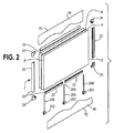
図1〜図3及び図7〜図15を参照すると、スクリーン組立体2は、周縁部6、並びに第1及び第2の対向する側面8、10を有するコア4を含むように示される。図1及び図2に示されるように、スクリーン組立体は、矩形形状の側面プロファイルを有することができ、又は、例えば図13に示されるように、他の非矩形の四角形又は多角形の形状を有することができる。スクリーンはまた、種々の円形、長楕円形、楕円形、卵形、又は他の形状を有することもできる。従って、スクリーンの縁部は直線状であってもよく、又は弧状であってもよく、又はこれらの組み合わせであってもよい。コア4は、ランバーコア、ファイバーボード、ファイバーマット、ガラス繊維マット充填材を有するポリウレタンフォームを含むフォームコアなどの単一の均質材料で作製することができ、又は、そうした材料の種々の層又は基材で形成することができる。コアは、1つ又はそれ以上の粘着性(tackable)層又は遮音層を含むことができる。コアは、例えば難燃特性を与えるために適用される外側スクリム12を含むことができる。
Screen Assembly Referring to FIGS. 1-3 and 7-15, the
周縁部の少なくとも一部分、及び1つの実施形態においては縁部の全周長は、そこから内方に延びる開口部14、16を含む。開口部は、連続的であっても、又は離間されていてもよい。1つの実施形態において、開口部は、縁部の中心に置かれた第1及び第2のチャネル14、16として構成される。チャネルは、名目上中心に置かれるが、例えば、許容公差に起因する厚さの変動によりチャネルが僅かに中心から外れてシフトすることがある。他の状況では、所望であれば、溝を一方の側又は他方の側のより近くに配置してもよい。第1のチャネルは、縁部6に向かって外方に開き、第1の幅を有する。縁部は、チャネルの両側に一対の踊り場(landing)18を定める。第2のチャネル16は、第1のチャネル14の底部から内方に延び、第2の幅を有し、この第2の幅は、第1の幅より狭い。種々の実施形態において、コア4は、実質的に平面状であるが、該コア4は、例えば1つ又はそれ以上の仮想垂直軸の周りで湾曲する非平坦形状を有してもよいことを理解されたい。
At least a portion of the peripheral edge, and in one embodiment, the entire circumference of the edge includes
図1〜図3及び図7〜図25を参照すると、縁部処理部(edge treatment)がコアの縁部6に結合され、縁部から、好ましくはコアによって定められる同じ平面内に外方に延びる。1つの実施形態において、縁部処理部は、複数の直線状部材22及び複数のコーナー部材24を含むリテーナ20として構成される。直線状部材は、好ましくは一体型のものであり、押出品として形成される。リテーナはまた、対応するコアの縁部のプロファイルに適合する非直線状の湾曲部材を含むこともできる。1つの実施形態において、複数のリテーナ20は、上方及び下方リテーナ部材と、対向する側部リテーナ部材22と、上方リテーナ部材と側部リテーナ部材との間及び下方リテーナ部材と側部リテーナ部材との間に配置されたコーナー・リテーナ部材24とを含む。コーナー・リテーナ部材は、上方及び下方リテーナ部材に接続される。1つの実施形態において、コーナー・リテーナ部材、並びに上方及び下方リテーナ部材の一方又は他方は、コーナー・リテーナ部材の他方の中に形成された開口部と嵌合し、これに受けられる挿入部分26を含み、上方及び下方リテーナ部材は、1つの実施形態において、上方及び下方リテーナ部材の内部キャビティ28として構成された開口部を含み、挿入部分は内部キャビティ内に配置される。
With reference to FIGS. 1-3 and FIGS. 7-25, an edge treatment is coupled to the
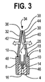
リテーナは、直線状部材、湾曲部材、又はコーナー部材のいずれであっても、口部34を定めるそれぞれの縁部部分36、38を有する第1及び第2の弾性リム30、32を含み、この口部34は、保持構成にある際に閉じること又は僅かな間隙を形成することができる。第1及び第2の弾性リム30、32は、これらの間に内部キャビティ28を定める。第1及び第2の弾性リムは、それぞれの外面40、42を定める。図3に示されるように、第1及び第2の弾性リム30、32の縁部部分は、保持構成と挿入構成との間で、互いに向かって及び互いから離れるように可動である。第1及び第2のリムは、外力がこれに印加されていないときは、保持構成の方向に互いに付勢される。縁部部分36、38は、スクリーン組立体の様々な最外縁部のプロファイルを与えるように構成することができる。例えば、リム及び縁部部分は、図3に示されるような三角形の断面を与えるように成形し、構成することができる。或いは、縁部部分を「四角にする(square off)」こともでき、比較的平坦な平面状の最外面を有することができる。
The retainer includes first and second
第1及び第2のリム30、32の各々は、内部キャビティ内に内方に延びる把持部材44を有する。この把持部材は、それぞれ内部キャビティ28内に挿入された、例えば布地層のような第1及び第2のカバー部分46、48に係合する。把持部材44は、カバー部分46、48の一方向の係合をもたらすように配向され、把持部材が、カバー部分の内部キャビティ内への挿入可能にするが、カバー部分の内部キャビティからの除去を防止するように構成される。把持部材は、フック、かぎ(barb)、小瘤(nodule)、又は他の適切な突起部として構成することができる。図15に示される1つの実施形態において、第1のリム30の把持部材44は、第2のリム32の把持部材に対して互い違いに配置されているので、カバー46、48は、把持部材の間を前後に縫うように進むことができ、それにより、カバーにかかる把持力が最大になる。
Each of the first and
図3及び図5に示されるように、リムの外面40、42は、コアの対向する側面に隣接する基部50からその縁部部分へテーパ状になっている。外面は、図3及び図5に示されるように実質的に平面状であってもよく、又は湾曲してもよく(凹状に又は凸状外方に)、又は図8、図12、図16及び図17に示されるように、非直線状若しくは非平面状プロファイルを有してもよい。第1及び第2のリムは基部から外方に延び、「外方に」という用語は、例えば円形の側面プロファイルを有するスクリーンから半径方向「外方に」など、コアのプロファイルから遠ざかり、概ねその範囲内にあるように定められる。基部は、コアの縁部6上の踊り場18に係合する、対向する外部隆起部54を含むことができる床部52を有し、これにより、例えば縁部に沿った反り又は公差の増加によって、リテーナ20が縁部上に適切に着座することを保証する。基部50は、コアのチャネル内に配置された挿入部材56を含む。挿入部材は、第1のチャネル14と嵌合し、その中に配置される第1の部分58と、第2のチャネル16内に配置されるアンカー部材60とを含むことができる。挿入部材を含む基部及びリムは、例えば押し出しによって一体的に形成することができる。基部の幅は、様々なコア厚を収容するように変更することができる。1つの実施形態において、基部の幅は、コアの幅より僅かに狭い。
As shown in FIGS. 3 and 5, the
図18〜図25を参照すると、リテーナ120は、各々が第1及び第2のリム130、132の一方を定める別個の半体122、124から形成される。これらの半体は、スクリュー126などの1つ又はそれ以上のファスナで、又は、スナップ式係合、接着剤、例えば音波溶接などの溶接、及び/又はこれらの組み合わせによって接続することができる。2部品リテーナは、コーナー部材又は部品に適するものとして示され、これらは、非直線状構成のために押し出しには適していない。直線状部品320、322、324(図6及び図21〜図25を参照されたい)は2部品で作製してもよいこと、及び、コーナー部品を一体品として成形できることを理解されたい。直線状部品322、324は、右用及び左用のものとすることができ、これらの組み合わせは、位置合わせされた挿入部分及びアンカー部分330と、ファスナを受けて半体を接続する突出部328とを含む。コーナー部品は、第1及び第2の直交する口部分134、136を定める第1及び第2のリム130、132を有する。各半体は一連の把持部材140で構成される。
With reference to FIGS. 18-25, the
図1〜図3及び図15を参照すると、第1及び第2のカバー部分46、48(明確にするために、部分図で示される)は、各々が周縁部70、72を有すように示され、カバー部分は、コア及び縁部処理部のプロファイルと概ね適合する側面プロファイルを有するが、縁部70、72がスクリーンの全ての側部上のリテーナの縁部部分36、38を超えて延びる状態でより大きい表面積を有する。第1のカバー部分46は、スクリム層を含むコアの第1の側、及び第1の弾性リム30の外面40の上に重なる。第2のカバー部分48は、コアの第2の側、及び第2の弾性リムの外面42の上に重なる。第1及び第2のカバー部分46、48は、第1及び第2のリムの縁部部分36、38の周りに巻き付き、縁部部分とリム30、32との間の口部34を通して配置されるので、第1及び第2のカバー部分の縁部70、72は内部キャビティ28内に配置され、第1及び第2の弾性リムは、それらの間に第1及び第2のカバー部分を保持する。第1及び第2のリムの把持部材44は、第1及び第2のカバー部分に係合する。カバー部分は、例えば、カバー部分がコア及び/又は縁部処理部の底縁部の周りに巻き付き、次いでカバーの自由縁部がスクリーンの他の3つの縁部に沿ってリテーナ内に固定されるように、一体の材料シートとして形成できることを理解されたい。カバーはまた、コアが、カバーによって形成されたエンベロープ又はバッグ状構造体の内部に嵌まった状態で、例えば縫うことによって、2つの他の側部に沿って又は3つの側部に沿って封止することも可能である。本実施形態において、カバーは、リテーナ内に固定された、その1つの側部のみに沿って形成された第1及び第2の部分を含む。カバー部分46、48は、接着剤によってコア及び/又はリテーナの外部に固定することができる。
1-3 and 15, the first and
図38及び図39を参照すると、ガラス繊維入りポリウレタンフォームから形成されたコア502を有する別のスクリーン500が示される。例えば押出品として形成された直線状縁部処理部506、及び、例えば射出成形によって形成されたコーナー縁部処理部504は、コアの外周の周りに位置決めされる。本実施形態において、カバー部分は省略され、コア及び縁部処理部がスクリーンの完成した外観を与える。
Referring to FIGS. 38 and 39, another
スクリーン支持体、コネクタ及びアクセサリ
図29及び図30を参照すると、スクリーン組立体の1つの実施形態が、第1及のカバー部分46と第2のカバー部分48との間で口部34を通してリテーナの内部キャビティ28内に配置することができる挿入部分92を有するアクセサリ接続部材90を含む。アクセサリ接続部材は、挿入部分に接続された支持部分94を有するクリップを含むことができる。1つの実施形態において、支持部分94は第1及び第2のカバー部分の少なくとも一方の上に重なり、第1及び第2のリム30、32のそれぞれのものの外面40、42に適合する輪郭をもった内面98を有する。支持体は、フック96、タブ、又は他のアクセサリ接続部を含むことができるので、スクリーン・オーバーレイ、棚、保管場所などのアクセサリに係合しそれを保持することができる。支持体はまた、コートのフック又は他のハンガーとして構成することもできる。1つの実施形態において、スクリーン・オーバーレイ100は、ホワイトボードなどの書き込み可能な表面として構成することができ、又は、モニタ面若しくは投影面などの表示面として構成することができる。フック96は、スクリーン・オーバーレイの上方部分に沿って形成されたチャネル102に係合する。図31を参照すると、代替的な接続部材104は、スクリーン組立体の縁部の上に受けられるチャネル108を定める、対向する支持部分106を含むことができ、支持部分はスクリーンの両側に沿って内方に延びる。支持部分の一方又は両方は、フックなどのアクセサリ接続部110を有するように構成することができる。
Screen Support, Connector and Accessories Referring to FIGS. 29 and 30, one embodiment of the screen assembly is shown in the retainer through the
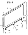
図2、図4及び図5を参照すると、スクリーン支持体200は、リテーナ20の一部分、具体的には、底縁部に結合されたリテーナの第1及び第2のリム30、32をその中に受けるように成形されたキャビティ204を有する支持ブロック202を含む。スクリーン支持体は、支持ブロックからコア4内に上向きに延びるバヨネット206をさらに含む。リテーナは、バヨネット206の通過を可能にするように間に空間208を有する、図2に示されるように離間された部分を含むことができる。平行四辺形として成形されたロック部材210は回転可能であり、支持ブロックを通って延びるねじ付き端部部分を有するバヨネット206の底部にねじ付けられて固定される。ロック部材は、該ロック部材がスクリーンの長さに沿って配向される非ロック位置と、ロック部材がスクリーンの長さに対して直交して配向されるロック位置との間で回転可能である。T字形状のソケット又は他の凹部(図示せず)が、作業面又は支持体壁などの隣接する構成要素上に配置されてロック部材を受け、スクリーンを構成要素に固定することができる。支持ブロックは、スクリーン・オーバーレイ部材100の下縁部に係合する直立壁212を含むことができる。
With reference to FIGS. 2, 4 and 5, the
図7、図9及び図34に示される代替的な実施形態において、スクリーン支持体220は、足部分224と、第1のカバー部分と第2のカバー部分との間のリテーナ20の口部34を通して、第1のリムと第2のリムとの間の内部キャビティ内に配置された上向きに延びる挿入部分222とを有する基部部材を含む。足部分224は、椅子又は作業面335などの隣接する基部構造体に固定することができる。
In the alternative embodiment shown in FIGS. 7, 9 and 34, the
図6、図21〜図25に示される別の実施形態において、2部品リテーナ320、322、324が、スクリーン支持体の一部を形成する支柱を受けるように成形された開口部226及びソケット228を定める第1及び第2のリムを含むように示される。リテーナは、コーナー部品又は直線状部品として形成することができる。支柱240は、図11及び図19に示されるように、リテーナにより完全に支持することができ、又は、図21〜図25に示されるように、リテーナを通ってコア内に形成された開口部の中に延びることができる。グライド321又は他の床部係合部材を支柱240の底部に固定することができ、また、支柱に対して高さ調整可能にしてレベリング機能を与えることができる。リテーナは、該リテーナを隣接するリテーナと位置合わせするのに用いられる挿入部分26を含む。
In another embodiment shown in FIGS. 6, 21-25, a two-
図32及び図33を参照すると、スクリーン支持体は、支柱240などの支持部材に接続されたフレーム250を含む。このフレームは、離間され、それらの間に間隙256を定める上方及び下方クランプ部材252、254を定める。間隙256は、テーブルトップ258などのクランプ面を内部に受けるように適合された大きさに作られる。1つ又はそれ以上のカム260(2つとして示される)が、上方又は下方クランプ部材254の一方又は両方に回転可能に取り付けられる。1つ又はそれ以上のカム260は、外側クランプ面266を有する。カム260は、外側クランプ面266が、上に取り付けられたパッド270を含む、上方又は下方クランプ部材252の他方から第1の距離だけ離間された非クランプ位置と、外側クランプ面が上方又は下方クランプ部材252、270の他方から第2の距離だけ離間されたクランプ位置との間で回転可能である。第2の距離は、第1の距離より短い。パッド270はまた、スクリーンの底縁部を支持することもできる。カムは、把持可能なハンドル部分268を含む。カムはまた、外側クランプ面と回転軸を定める孔との間に配置された内部キャビティ276も含み、それにより、カムの弾性が増大する。
With reference to FIGS. 32 and 33, the screen support includes a
図35及び図36を参照すると、コネクタ280は、例えば隣接する側縁部などの、隣接するスクリーン組立体2の縁部部分を接続するように構成される。コネクタ280は、第1及び第2のスクリーンの隣接する縁部処理部の口部34を通して受けられる第1及び第2の挿入部分282、284を含む。縁部処理部又はリテーナの各々はチャネル56を含み、第1及び第2の挿入部分は各々、チャネルの表面に係合する弾性バーブとして示される少なくとも1つの一方向把持部材286を有する。挿入部分282、284の各々は、切れ目385を通して、例えば図13に示される縁部処理部内に挿入される細長い舌部283、284を含むことができる。
With reference to FIGS. 35 and 36, the
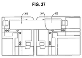
図26〜図28及び図37を参照すると、コネクタ300が、直線の関係で配向されようと又は直交する関係で配向されようと、対向するフランジ302、304を有するように示され、各フランジの端部は回転されて、キャッチ部分306を形成する。把持可能なタブ部分308は、フランジ間の中心にある。フランジ302、304は、隣接する縁部処理部の弾性リム部分130と132との間に受けられ、キャッチ部分は、リテーナ20の内部キャビティ28内に配置される。図37に示されるように、コネクタ301は、スクリーンの中心面に沿って延び、1つの実施形態においては一体成形され、縁部処理部内に成形されたボス307上に載っている対向するフランジ303、305を有する。ボスは、ファスナ・レセプタクルとして機能することができる。
Referring to FIGS. 26-28 and 37, the
図34を参照すると、押しピン固定機構341が示される。受け部材345を含むブラケット343が、椅子、作業面、デスク、キャビネット、又は他の自立構造体などの基部335に固定される。押しピン347は、パネルの中央の開口部349を通して挿入し、その後、受け部材345内に形成されたソケット内に受けることができる。押しピン347は、パネルの表面に係合するフランジを有するヘッド部分353と、例えばピンの端部上の、押しボタン351により作動される戻り止めなどの解放機構とを含む。解放機構を作動させてピンを受け部材から解放し、ピンを引き抜き、パネルを取り外すことができる。
Referring to FIG. 34, a push pin fixing mechanism 341 is shown. A
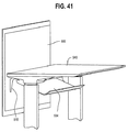
図38〜図41を参照すると、複数の挿入体(2つとして示される)の各々が、スクリーン500の1つの表面に埋め込まれたフランジを有する。挿入体は、接着剤516で固定され、フランジからコア502の厚さを通って形成された開口部514内に延びる複数のボス構造体512(2つとして示される)を含む。対応する複数のブラケット518は、スクリーン500の対向する面に係合するフランジ520を有する。複数のファスナ522は、フランジの開口部を通って延び、ボス構造体512に係合し、コア502はブラケット518と挿入体510との間にクランプされる。ブラケットは、直立アーム524と、作業面540などの隣接する基部に固定された取り付けフランジ526とを含み、スクリーンは、スクリーンの下方部分528が作業面の下方に配置されて幕スクリーン(modesty screen)を提供し、上方部分530が作業面の上方に延びてプライバシースクリーンを提供するように、地面の上に吊るされる。アームは開口部532を含み、この開口部532は、作業面の下にピボット運動可能に取り付けられたワイヤトレイ534のためのピボット取り付けをもたらす。
With reference to FIGS. 38-41, each of the plurality of inserts (shown as two) has a flange embedded in one surface of the
本発明を好ましい実施形態を参照して説明したが、当業者であれば、本発明の趣旨及び範囲から逸脱することなく、形態及び詳細に対して変更を行い得ることを認識するであろう。従って、上記の詳細な説明は例示のためのものであって限定するためのものではないと考えられるべきであり、本発明の範囲を定めるように意図されるのは、その全ての均等物を含む添付の特許請求の範囲であることが意図される。 Although the present invention has been described with reference to preferred embodiments, workers skilled in the art will recognize that changes may be made in form and detail without departing from the spirit and scope of the invention. Accordingly, the above detailed description is to be construed as illustrative and not restrictive, and all equivalents thereof are intended to define the scope of the invention. The accompanying claims are intended to be included.
2:スクリーン組立体
4、502:コア
6:周縁部
8:第1の側面
10:第2の側面
14、16、56、102、108:チャネル
20、120:リテーナ
22:側部リテーナ部材
24:コーナー部材
26、92、222、282、284:挿入部分
:挿入部分
28、204、276:内部キャビティ
30:第1のリム
32:第2のリム
34:口部
36:第1の縁部部分
38:第2の縁部部分
40、42:外面
44、140:把持部材
46:第1のカバー部分
48:第2のカバー部分
50、335:基部
52:床部
56、222:挿入部材
58:第1の部分
60:アンカー部材
90:アクセサリ接続部材
94、106:支持部分
96:フック
98:内面
100:スクリーン・オーバーレイ
110:アクセサリ接続部
122、124:半体
130、132:リム部分
134、136:口部分
200:スクリーン支持体
202:支持ブロック
206:バヨネット
220:スクリーン支持体
226、349、514、532:開口部
240:支柱
250:フレーム
252、254:クランプ部材
256:間隙
258:テーブルトップ
260:カム
280、300:コネクタ
282、284:挿入部分
302、303、304、305、520:フランジ
320、322、324:直線状部品
321:グライド
335、540:作業面
343、518:ブラケット
500:スクリーン
504:コーナー縁部処理部
506:直線状縁部処理部
518:ブラケット
522:ファスナ
2: Screen assembly 4, 502: Core 6: Peripheral portion 8: First side surface 10: Second side surface 14, 16, 56, 102, 108: Channel 20, 120: Retainer 22: Side retainer member 24: Corner members 26, 92, 222, 282, 284: Insertion part: Insertion part 28, 204, 276: Internal cavity 30: First rim 32: Second rim 34: Mouth 36: First edge part 38 : Second edge portion 40, 42: outer surface 44, 140: gripping member 46: first cover portion 48: second cover portion 50, 335: base 52: floor 56, 222: insertion member 58: first 1 part 60: anchor member 90: accessory connection member 94, 106: support part 96: hook 98: inner surface 100: screen overlay 110: accessory connection part 122, 124: half 13 132: rim portion 134, 136: mouth portion 200: screen support 202: support block 206: bayonet 220: screen support 226, 349, 514, 532: opening 240: support column 250: frame 252, 254: clamp member 256: Gap 258: Table top 260: Cam 280, 300: Connector 282, 284: Insertion portions 302, 303, 304, 305, 520: Flange 320, 322, 324: Linear part 321: Glide 335, 540: Work surface 343, 518: Bracket 500: Screen 504: Corner edge processing unit 506: Linear edge processing unit 518: Bracket 522: Fastener
Claims (29)
前記コアの前記縁部に結合され、前記コアから外方に延び、口部を定めるそれぞれの縁部部分を有する第1及び第2の弾性リムを含むリテーナであって、前記第1及び第2の弾性リムはそれらの間に内部キャビティを定め、かつ、それぞれの外面を定め、前記第1及び第2の弾性リムの前記縁部部分は、保持構成と挿入構成との間で互いに向かって及び互いから離れるように可動であり、前記第1及び第2のリムは、前記保持構成の方向に付勢されている、リテーナと、
各々が縁部を有する第1及び第2のカバー部分と、
を備え、
前記第1のカバー部分は、前記コアの前記第1の側面及び前記第1の弾性リムの前記外面の上に重なり、前記第2のカバー部分は、前記コアの前記第2の側面及び第2の弾性リムの前記外面の上に重なり、前記第1及び第2のリムの前記縁部部分の周りに巻き付く前記第1及び第2のカバー部分は、前記口部を通して配置され、前記第1及び第2のカバー部分の前記縁部は前記内部キャビティ内に配置され、前記第1及び第2の弾性リムはそれらの間に前記第1及び第2のカバー部分を保持するようになることを特徴とするスクリーン組立体。 A core having an edge and first and second opposing sides;
A retainer including first and second elastic rims coupled to the edge of the core, extending outwardly from the core and having respective edge portions defining a mouth, the first and second The elastic rims define internal cavities therebetween and define respective outer surfaces, the edge portions of the first and second elastic rims extending toward each other between the holding configuration and the insertion configuration A retainer, movable away from each other, wherein the first and second rims are biased in the direction of the holding configuration;
First and second cover portions each having an edge;
With
The first cover portion overlies the outer surface of the first side surface and the first elastic rim of the core, said second cover portion, said second side surface of said core and The first and second cover portions overlying the outer surface of a second elastic rim and wrapping around the edge portions of the first and second rims are disposed through the mouth; The edges of the first and second cover portions are disposed within the internal cavity, and the first and second elastic rims hold the first and second cover portions therebetween. A screen assembly characterized by that.
前記チャネルは、第1の幅を有する第1のチャネルと、前記第1のチャネルと連通し、第2の幅を有する第2のチャネルとを含み、前記第2の幅は前記第1の幅より狭く、
前記基部は、前記チャネル内に配置された第1の部分と、前記第2のチャネル内に配置されたアンカー部材とを含むことを特徴とする、請求項14に記載のスクリーン組立体。 The opening includes a channel;
The channel includes a first channel having a first width and a second channel in communication with the first channel and having a second width, the second width being the first width. Narrower,
The screen assembly of claim 14, wherein the base includes a first portion disposed in the channel and an anchor member disposed in the second channel.
Applications Claiming Priority (3)
| Application Number | Priority Date | Filing Date | Title |
|---|---|---|---|
| US201361792639P | 2013-03-15 | 2013-03-15 | |
| US61/792,639 | 2013-03-15 | ||
| PCT/US2014/028012 WO2014143861A1 (en) | 2013-03-15 | 2014-03-14 | Screen assembly |
Publications (3)
| Publication Number | Publication Date |
|---|---|
| JP2016522336A JP2016522336A (en) | 2016-07-28 |
| JP2016522336A5 JP2016522336A5 (en) | 2016-11-24 |
| JP6325076B2 true JP6325076B2 (en) | 2018-05-16 |
Family
ID=51727921
Family Applications (1)
| Application Number | Title | Priority Date | Filing Date |
|---|---|---|---|
| JP2016502685A Active JP6325076B2 (en) | 2013-03-15 | 2014-03-14 | Screen assembly |
Country Status (7)
| Country | Link |
|---|---|
| US (2) | US9255440B2 (en) |
| EP (1) | EP2971396B1 (en) |
| JP (1) | JP6325076B2 (en) |
| CN (1) | CN105358775B (en) |
| BR (1) | BR112015022118B8 (en) |
| HK (1) | HK1221493A1 (en) |
| MX (1) | MX2015012355A (en) |
Families Citing this family (19)
| Publication number | Priority date | Publication date | Assignee | Title |
|---|---|---|---|---|
| USD737600S1 (en) * | 2013-11-05 | 2015-09-01 | Linda Bovay | Screen |
| US10132078B2 (en) | 2015-08-10 | 2018-11-20 | Herman Miller, Inc. | Screen assembly |
| US10758053B2 (en) | 2017-12-12 | 2020-09-01 | Bobachi, Llc | Screen |
| US20190242182A1 (en) * | 2018-02-05 | 2019-08-08 | L&P Property Management Company | Knock Down Privacy Screen Assembly and Method of Assembling Same |
| CN108497775A (en) * | 2018-04-20 | 2018-09-07 | 佛山市龙生光启科技有限公司 | A kind of intelligence bar desk |
| US10973321B2 (en) | 2018-09-04 | 2021-04-13 | Steelcase Inc. | Workspace system and components and method for the use thereof |
| US11191178B2 (en) | 2019-01-24 | 2021-11-30 | Steelcase Inc. | Display support system and method for the use thereof |
| USD937013S1 (en) * | 2020-04-29 | 2021-11-30 | William Thomas SMITH | Barrier stand |
| USD931655S1 (en) * | 2020-08-11 | 2021-09-28 | R.A.S. Developments, Llc | Partition apparatus |
| WO2022020136A1 (en) | 2020-07-23 | 2022-01-27 | Steelcase Inc. | Display support system and method for the use thereof |
| US10973325B1 (en) * | 2020-08-28 | 2021-04-13 | Goff's Enterprises, Inc. | Desk top safety partition |
| AU2021106604B4 (en) * | 2021-05-28 | 2022-04-14 | Thinking Ergonomix Pty Limited | Workplace privacy screen and kit for the same |
| KR200497069Y1 (en) * | 2021-08-09 | 2023-07-17 | 뷰로맥스 주식회사 | Screen Panel Assembly |
| USD992322S1 (en) | 2021-09-24 | 2023-07-18 | Steelcase Inc. | Work area screen |
| USD992311S1 (en) | 2021-09-24 | 2023-07-18 | Steelcase Inc. | Work area screen |
| USD1000844S1 (en) | 2021-09-24 | 2023-10-10 | Steelcase Inc. | Work area screen |
| USD992323S1 (en) | 2021-09-24 | 2023-07-18 | Steelcase Inc. | Work area screen |
| USD1001518S1 (en) | 2021-09-24 | 2023-10-17 | Steelcase Inc. | Work area screen |
| KR102597786B1 (en) * | 2023-02-01 | 2023-11-03 | (주)선명테크 | Partition panel |
Family Cites Families (47)
| Publication number | Priority date | Publication date | Assignee | Title |
|---|---|---|---|---|
| US2981583A (en) | 1958-09-29 | 1961-04-25 | Eisenberg Edward | Desk privacy partition |
| US3249351A (en) | 1961-12-26 | 1966-05-03 | Wilfred A Smith | Clamp |
| US3949827A (en) * | 1975-04-24 | 1976-04-13 | Owens-Corning Fiberglas Corporation | Acoustical panel assembly |
| US4012880A (en) * | 1976-04-28 | 1977-03-22 | American Store Equipment Corporation | Partition system |
| US4213493A (en) * | 1979-01-24 | 1980-07-22 | Haworth Mfg., Inc. | Fabric retainer for panel |
| US4263761A (en) * | 1979-02-09 | 1981-04-28 | Kristoff Kim C | Portable acoustical panel system |
| JPS58129871U (en) * | 1982-02-26 | 1983-09-02 | 株式会社イト−キ | partition panel |
| US4624083A (en) | 1983-12-05 | 1986-11-25 | Hauserman, Inc. | Screen system for offices and method of making and installing same |
| US5024030A (en) * | 1983-12-13 | 1991-06-18 | Knoll International, Inc. | Space divider system |
| US4684425A (en) * | 1984-08-16 | 1987-08-04 | Bannister Brian C | Method of making cloth covered panels having edging strips |
| SE458129B (en) * | 1985-01-22 | 1989-02-27 | Sune Sigfrid Lennart Rydqvist | SKAERMVAEGGSYSTEM |
| US4593508A (en) * | 1985-04-11 | 1986-06-10 | Frank Curatolo | Extrusion |
| JPS6368852U (en) * | 1986-10-25 | 1988-05-09 | ||
| US4944416A (en) * | 1988-11-21 | 1990-07-31 | Petersen Robert J | Light-weight slot-wall display panel |
| US5172529A (en) * | 1991-01-22 | 1992-12-22 | Herman Miller, Inc. | Hinged wire management cover panel |
| US5423151A (en) * | 1991-09-13 | 1995-06-13 | Herman Miller, Inc. | Tackable tile |
| US5228579A (en) * | 1992-04-21 | 1993-07-20 | Bon Art International | Merchandise display panel |
| ATE108849T1 (en) * | 1992-08-10 | 1994-08-15 | Steelcase Strafor Sa | MODULAR PARTITION SYSTEM. |
| US5531539A (en) * | 1993-02-12 | 1996-07-02 | Exposystems, Inc. | Tightly fitting panel connection assembly |
| US6141926A (en) * | 1995-10-26 | 2000-11-07 | Tetrad Marketing/Sales Ltd. | Panel construction and connection system |
| CA2161459A1 (en) * | 1995-10-26 | 1997-04-27 | V. Paul Rossiter | Panel construction |
| US5890325A (en) * | 1996-08-22 | 1999-04-06 | Steelcase Inc. | Reconfigurable system for subdividing building space and having minimal footprint |
| US5682719A (en) * | 1996-07-15 | 1997-11-04 | Huang; Chin-Fa | Screen combination |
| US5689924A (en) * | 1996-10-07 | 1997-11-25 | Hon Industries, Inc. | Construction of modular office panel systems |
| US5733001A (en) | 1996-11-19 | 1998-03-31 | Roberts; Clifford D. | Seat cover retainer apparatus and method of using same |
| CA2198829A1 (en) * | 1997-02-28 | 1998-08-28 | Global Upholstery Company | Lightweight panel structure |
| US6044982A (en) | 1997-10-04 | 2000-04-04 | Stuart Shelving, Llc | Lever clamp |
| US5970669A (en) * | 1998-05-08 | 1999-10-26 | Livingston; Bryan K. | Molding strips for fabric wall and ceiling systems |
| EP0965296A1 (en) * | 1998-06-18 | 1999-12-22 | Fehlbaum & Co. | Article display device |
| DE19844027A1 (en) * | 1998-09-25 | 2000-03-30 | Preform Raumgliederungssysteme | Connecting element for connecting two components of a partition and use of such a connecting element |
| GB2345846A (en) * | 1999-01-21 | 2000-07-26 | Screen Solutions Limited | Screen assembly |
| JP2001178573A (en) * | 1999-12-24 | 2001-07-03 | Itoki Crebio Corp | Panel device |
| EP1134325A1 (en) * | 2000-03-01 | 2001-09-19 | Ziur I, S.L. | Partition screen |
| US6499262B1 (en) * | 2000-09-11 | 2002-12-31 | Frank Novak & Sons, Inc. | Ceiling panel |
| US6533479B2 (en) * | 2000-12-21 | 2003-03-18 | Pent Products | Integral keyboard/tray/wrist rest |
| US6574936B1 (en) | 2001-05-11 | 2003-06-10 | Accutrack Systems, Inc. | Fabric wall panel system |
| DE20108739U1 (en) * | 2001-05-23 | 2002-10-02 | Fitz Johannes | module |
| JP2003239922A (en) * | 2002-02-15 | 2003-08-27 | Takano Co Ltd | Attaching structure for film like member |
| CN2640343Y (en) * | 2003-08-12 | 2004-09-15 | 上海优格装潢有限公司 | Side sealed structure of screen panel |
| US20070125016A1 (en) * | 2005-11-18 | 2007-06-07 | Shawn Yu | Wall panel with corner-connected open frame |
| JP4685639B2 (en) * | 2006-01-13 | 2011-05-18 | 株式会社岡村製作所 | Extension board mounting structure |
| EP2063747B1 (en) * | 2006-09-06 | 2013-05-22 | 3M Innovative Properties Company | Horizontally mounted shelf assembly and accessories therefor |
| CN201234754Y (en) * | 2008-07-18 | 2009-05-13 | 东莞市兄奕塑胶制品有限公司 | Office furniture edge sealing strip |
| JP5513731B2 (en) * | 2008-11-10 | 2014-06-04 | 株式会社内田洋行 | panel |
| CN201372500Y (en) * | 2009-01-08 | 2009-12-30 | 罗敏 | Novel combined linear connection structure |
| DE102009012527A1 (en) * | 2009-03-05 | 2010-09-09 | Haver & Boecker Ohg | Facade element and method of manufacture |
| WO2011100135A1 (en) * | 2010-02-11 | 2011-08-18 | Herman Miller, Inc. | Wall mounted assembly |
-
2014
- 2014-03-14 EP EP14762219.5A patent/EP2971396B1/en active Active
- 2014-03-14 CN CN201480027723.9A patent/CN105358775B/en active Active
- 2014-03-14 MX MX2015012355A patent/MX2015012355A/en unknown
- 2014-03-14 JP JP2016502685A patent/JP6325076B2/en active Active
- 2014-03-14 US US14/213,487 patent/US9255440B2/en active Active
- 2014-03-14 BR BR112015022118A patent/BR112015022118B8/en active IP Right Grant
-
2016
- 2016-01-04 US US14/987,167 patent/US20160115732A1/en not_active Abandoned
- 2016-08-10 HK HK16109492.6A patent/HK1221493A1/en unknown
Also Published As
| Publication number | Publication date |
|---|---|
| CN105358775A (en) | 2016-02-24 |
| BR112015022118B8 (en) | 2022-08-02 |
| US20140311036A1 (en) | 2014-10-23 |
| EP2971396A1 (en) | 2016-01-20 |
| JP2016522336A (en) | 2016-07-28 |
| EP2971396A4 (en) | 2016-12-07 |
| CN105358775B (en) | 2017-12-22 |
| HK1221493A1 (en) | 2017-06-02 |
| MX2015012355A (en) | 2016-06-06 |
| BR112015022118A2 (en) | 2017-07-18 |
| BR112015022118B1 (en) | 2021-12-07 |
| EP2971396B1 (en) | 2017-10-25 |
| US20160115732A1 (en) | 2016-04-28 |
| US9255440B2 (en) | 2016-02-09 |
Similar Documents
| Publication | Publication Date | Title |
|---|---|---|
| JP6325076B2 (en) | Screen assembly | |
| JP6556263B2 (en) | Privacy screen device | |
| US10196816B2 (en) | Ceiling system | |
| US20200268175A1 (en) | Furniture | |
| AU2014228081B2 (en) | Screen assembly | |
| CA3003279C (en) | Ceiling system | |
| KR20090009911U (en) | Structure for covering frame of fittings | |
| JP3186945U (en) | Rack structure | |
| KR20150078788A (en) | Assembled partition | |
| JP7243255B2 (en) | Suspension fittings and assembled furniture with suspension fittings | |
| CN212852897U (en) | Laminate bracket and wall cabinet using same | |
| AU2017254873B2 (en) | Surface Mounted Furniture Having Concealed Mount | |
| JP7000673B2 (en) | Screens and booths | |
| JP2012125328A (en) | Partition plate with frame body | |
| JP2010229619A (en) | Wiring duct device of partition unit | |
| JP2010194224A (en) | Mounting structure of panel for desk |
Legal Events
| Date | Code | Title | Description |
|---|---|---|---|
| A521 | Request for written amendment filed |
Free format text: JAPANESE INTERMEDIATE CODE: A523 Effective date: 20161006 |
|
| A621 | Written request for application examination |
Free format text: JAPANESE INTERMEDIATE CODE: A621 Effective date: 20161006 |
|
| RD04 | Notification of resignation of power of attorney |
Free format text: JAPANESE INTERMEDIATE CODE: A7424 Effective date: 20170420 |
|
| A977 | Report on retrieval |
Free format text: JAPANESE INTERMEDIATE CODE: A971007 Effective date: 20170927 |
|
| A131 | Notification of reasons for refusal |
Free format text: JAPANESE INTERMEDIATE CODE: A131 Effective date: 20171002 |
|
| A521 | Request for written amendment filed |
Free format text: JAPANESE INTERMEDIATE CODE: A523 Effective date: 20171220 |
|
| TRDD | Decision of grant or rejection written | ||
| A01 | Written decision to grant a patent or to grant a registration (utility model) |
Free format text: JAPANESE INTERMEDIATE CODE: A01 Effective date: 20180312 |
|
| A61 | First payment of annual fees (during grant procedure) |
Free format text: JAPANESE INTERMEDIATE CODE: A61 Effective date: 20180411 |
|
| R150 | Certificate of patent or registration of utility model |
Ref document number: 6325076 Country of ref document: JP Free format text: JAPANESE INTERMEDIATE CODE: R150 |
|
| R250 | Receipt of annual fees |
Free format text: JAPANESE INTERMEDIATE CODE: R250 |
|
| R250 | Receipt of annual fees |
Free format text: JAPANESE INTERMEDIATE CODE: R250 |
|
| S533 | Written request for registration of change of name |
Free format text: JAPANESE INTERMEDIATE CODE: R313533 |
|
| R350 | Written notification of registration of transfer |
Free format text: JAPANESE INTERMEDIATE CODE: R350 |
|
| R250 | Receipt of annual fees |
Free format text: JAPANESE INTERMEDIATE CODE: R250 |