JP6323742B2 - Zoom lens, lens unit, and imaging apparatus - Google Patents
Zoom lens, lens unit, and imaging apparatus Download PDFInfo
- Publication number
- JP6323742B2 JP6323742B2 JP2013252797A JP2013252797A JP6323742B2 JP 6323742 B2 JP6323742 B2 JP 6323742B2 JP 2013252797 A JP2013252797 A JP 2013252797A JP 2013252797 A JP2013252797 A JP 2013252797A JP 6323742 B2 JP6323742 B2 JP 6323742B2
- Authority
- JP
- Japan
- Prior art keywords
- lens
- lens group
- refractive power
- zoom
- zoom lens
- Prior art date
- Legal status (The legal status is an assumption and is not a legal conclusion. Google has not performed a legal analysis and makes no representation as to the accuracy of the status listed.)
- Active
Links
Images


Classifications
-
- G—PHYSICS
- G02—OPTICS
- G02B—OPTICAL ELEMENTS, SYSTEMS OR APPARATUS
- G02B15/00—Optical objectives with means for varying the magnification
- G02B15/14—Optical objectives with means for varying the magnification by axial movement of one or more lenses or groups of lenses relative to the image plane for continuously varying the equivalent focal length of the objective
- G02B15/16—Optical objectives with means for varying the magnification by axial movement of one or more lenses or groups of lenses relative to the image plane for continuously varying the equivalent focal length of the objective with interdependent non-linearly related movements between one lens or lens group, and another lens or lens group
- G02B15/163—Optical objectives with means for varying the magnification by axial movement of one or more lenses or groups of lenses relative to the image plane for continuously varying the equivalent focal length of the objective with interdependent non-linearly related movements between one lens or lens group, and another lens or lens group having a first movable lens or lens group and a second movable lens or lens group, both in front of a fixed lens or lens group
- G02B15/167—Optical objectives with means for varying the magnification by axial movement of one or more lenses or groups of lenses relative to the image plane for continuously varying the equivalent focal length of the objective with interdependent non-linearly related movements between one lens or lens group, and another lens or lens group having a first movable lens or lens group and a second movable lens or lens group, both in front of a fixed lens or lens group having an additional fixed front lens or group of lenses
- G02B15/173—Optical objectives with means for varying the magnification by axial movement of one or more lenses or groups of lenses relative to the image plane for continuously varying the equivalent focal length of the objective with interdependent non-linearly related movements between one lens or lens group, and another lens or lens group having a first movable lens or lens group and a second movable lens or lens group, both in front of a fixed lens or lens group having an additional fixed front lens or group of lenses arranged +-+
Description
本発明はズームレンズ、レンズユニット及び撮像装置に関するものであり、例えば被写体の静止画や動画を撮像素子で取りこむためのオプティカルユニット等に用いられ、特に高変倍率を有するとともに像ブレ補正機能を有し、小型化・薄型化・広角化可能なズームレンズ、及び該ズームレンズを備えたレンズユニット並びに撮像装置に関するものである The present invention relates to a zoom lens, a lens unit, and an image pickup apparatus. For example, the present invention is used in an optical unit for capturing a still image or a moving image of a subject with an image pickup element, and particularly has a high zoom ratio and an image blur correction function. The present invention relates to a zoom lens that can be reduced in size, thickness, and angle, a lens unit including the zoom lens, and an imaging device.
従来より、カメラの厚み寸法を小さくできる光学系として、ズームレンズ中の最も物体側のレンズ群である第1レンズ群にプリズム等の反射部材を用いて光軸を折り曲げる(屈曲させる)屈曲光学系が広く用いられている。このような屈曲光学系をカメラに搭載することで、使用時にカメラ本体よりレンズが繰り出さずに済むため、カメラの防水性、耐衝撃性を向上させることが可能となる。 2. Description of the Related Art Conventionally, as an optical system that can reduce the thickness of a camera, a bending optical system that bends (bends) an optical axis using a reflecting member such as a prism in a first lens group that is a lens group closest to the object in a zoom lens. Is widely used. By mounting such a bending optical system on the camera, it is possible to improve the waterproofness and impact resistance of the camera because the lens does not have to be extended from the camera body during use.
一方、撮像装置の薄型化のニーズに加え、最近では、ズームレンズの高変倍化や広角化、大口径化のニーズがある。このような撮像装置へのニーズに対応した光学系が、以下の特許公報に開示されている(例えば、特許文献1,2参照)。 On the other hand, in addition to the need for thinner imaging devices, recently there is a need for higher zooming, wider angles, and larger apertures for zoom lenses. An optical system corresponding to the needs for such an imaging apparatus is disclosed in the following patent publications (see, for example, Patent Documents 1 and 2).
しかるに、特許文献1に記載されたズームレンズは、4群構成と簡素ではあるが、焦点距離の広角化が図られていないという問題がある。また、特許文献2に記載されたズームレンズは5群構成で焦点距離の広角化が図られているが、広角端Fナンバーが大きい(暗い)という問題があり、焦点距離の広角化や明るさを同時に満たしていない。 However, the zoom lens described in Patent Document 1 is simple with a four-group configuration, but has a problem that the focal length is not widened. In addition, the zoom lens described in Patent Document 2 has a five-group configuration in which the focal length is widened. However, there is a problem that the wide-angle end F-number is large (dark). Is not satisfied at the same time.
本発明は、上述した問題に鑑み、広角化に対応でき、明るいFナンバーを確保し、さらに諸収差が良好に補正されたズームレンズおよびそのズームレンズを搭載したレンズユニット並びに撮像装置を提供することを目的とする。 In view of the above-described problems, the present invention provides a zoom lens that can cope with widening of the angle, secures a bright F-number, and corrects various aberrations well, a lens unit including the zoom lens, and an imaging apparatus. With the goal.
請求項1に記載のズームレンズは、物体側より順に配置された、変倍時に移動しない正の屈折力を有する第1レンズ群と、変倍時に光軸に沿って移動する負の屈折力を有する第2レンズ群と、絞りを含み変倍時に移動しない正の屈折力を有する第3レンズ群と、変倍時に光軸に沿って移動する正の屈折力を有する第4レンズ群と、変倍時に移動しない第5レンズ群とから構成されたズームレンズにおいて
前記第1レンズ群は光軸を屈曲させるための反射部材を有し、
前記第4レンズ群は物体側から順に、負の屈折力を有する第41レンズと、正の屈折力を有する第42レンズで構成され、
前記第5レンズ群は物体側から順に負の屈折力を有する第51レンズ、正の屈折力を有する第52レンズ、第53レンズで構成され、以下の条件式を満足することを特徴とする。
−1.50 < f2/fw < −1.00 (1)
3.30 < f4/fw < 4.30 (2)
0.3 < |β4T/β4W| < 1.0 (3)
1.0 < d2wt/d4wt <1.7 (9)
但し、
f2:前記第2レンズ群の焦点距離(mm)
f4:前記第4レンズ群の焦点距離(mm)
fw:広角端での全系の合成焦点距離(mm)
β4W:前記第4レンズ群の広角端における横倍率
β4T:前記第4レンズ群の望遠端における横倍率
d2wt:変倍に際して前記第2レンズ群が広角端から望遠端まで移動する距離(mm)
d4wt:変倍に際して前記第4レンズ群が広角端から望遠端まで移動する距離(mm)
The zoom lens according to claim 1 includes a first lens group arranged in order from the object side and having a positive refractive power that does not move during zooming, and a negative refractive power that moves along the optical axis during zooming. A second lens group having a stop, a third lens group having a positive refractive power that does not move at the time of zooming, and a fourth lens group having a positive refractive power that moves along the optical axis at the time of zooming, In a zoom lens constituted by a fifth lens group that does not move at the time of magnification, the first lens group has a reflecting member for bending the optical axis,
The fourth lens group includes, in order from the object side, a forty-first lens having negative refractive power and a forty-second lens having positive refractive power,
The fifth lens group includes a 51st lens having a negative refractive power, a 52nd lens having a positive refractive power, and a 53rd lens in order from the object side, and satisfies the following conditional expression.
−1.50 <f2 / fw <−1.00 (1)
3.30 <f4 / fw <4.30 (2)
0.3 <| β4T / β4W | <1.0 (3)
1.0 <d2wt / d4wt <1.7 (9)
However,
f2: Focal length (mm) of the second lens group
f4: Focal length (mm) of the fourth lens group
fw: Total focal length of the entire system at the wide-angle end (mm)
β4W: lateral magnification at the wide-angle end of the fourth lens group β4T: lateral magnification at the telephoto end of the fourth lens group
d2 wt: Distance (mm) by which the second lens unit moves from the wide-angle end to the telephoto end during zooming
d4 wt: Distance (mm) by which the fourth lens group moves from the wide-angle end to the telephoto end during zooming
本発明の基本構成は、物体側から順に、正の屈折力を有する第1レンズ群と、負の屈折力を有する第2レンズ群と、正の屈折力を有する第3レンズ群と、正の屈折力を有する第4レンズ群と、第5レンズ群からなる。 The basic configuration of the present invention includes, in order from the object side, a first lens group having a positive refractive power, a second lens group having a negative refractive power, a third lens group having a positive refractive power, and a positive lens It consists of a fourth lens group having refractive power and a fifth lens group.
そして、前記第1レンズ群、前記第3レンズ群、前記第5レンズ群は変倍もしくは合焦時に光軸方向に移動しない構成となる。前記第1レンズ群を固定することで、撮影時に最も物体側のレンズが飛び出さないので、撮影の対象者に圧迫感を与える恐れを回避できる。また、撮像装置を誤って落下させたときなど、最も物体側のレンズが飛び出していない構成であれば、落下の衝撃による影響も少なくて済むので好ましい。更に、前記第3レンズ群を固定することで、前記第3レンズ群が可変絞り機構を有する場合でも、構造が複雑化せず容易な機構となる。又、前記第5レンズ群を固定することによって、前記第5レンズ群の最も像側のレンズと固体撮像素子との間の空間を封止することができるようになり、撮像素子へのゴミや埃の進入を防ぐことができる。 The first lens group, the third lens group, and the fifth lens group are configured not to move in the optical axis direction during zooming or focusing. By fixing the first lens group, the lens on the most object side does not pop out at the time of photographing, so that it is possible to avoid the possibility of giving a sense of pressure to the subject of photographing. In addition, when the image pickup apparatus is accidentally dropped, a configuration in which the lens closest to the object does not protrude is preferable because the influence of the impact of the drop can be reduced. Further, by fixing the third lens group, even when the third lens group has a variable aperture mechanism, the structure is not complicated and an easy mechanism is obtained. Also, by fixing the fifth lens group, it becomes possible to seal the space between the lens closest to the image side of the fifth lens group and the solid-state image sensor, Ingress of dust can be prevented.
また、前記第2レンズ群、前記第4レンズ群は変倍時若しくは合焦時に、光軸に沿って移動する構成となっており、広角端から望遠端に至る変倍動作時に、前記第2レンズ群を像側方向に変位させ、且つ前記第4レンズ群を物体側方向に移動させることにより、2つのレンズ群に変倍機能を分担できるので、単一レンズ群のみで変倍を行うよりも群パワーや変倍移動量を抑え、コンパクト性と良好な光学性能を両立することができる。 Further, the second lens group and the fourth lens group are configured to move along the optical axis at the time of zooming or focusing, and at the time of zooming operation from the wide angle end to the telephoto end, By displacing the lens group in the image side direction and moving the fourth lens group in the object side direction, the magnification function can be shared by the two lens groups. In addition, the group power and zooming movement amount can be suppressed, and both compactness and good optical performance can be achieved.
前記第1レンズ群は、光軸を屈曲させる(折り曲げる)ための反射部材を有しており、これによって入射光軸方向の大きさが小さくなるので、撮像装置の奥行き方向の大きさ(厚み)を小さくすることが出来る。 The first lens group has a reflecting member for bending (bending) the optical axis, and this reduces the size in the incident optical axis direction, so that the size (thickness) in the depth direction of the imaging device is reduced. Can be reduced.
前記第4レンズ群は、物体側より順に負の屈折力を有するレンズ(第41レンズ)、正の屈折力を有するレンズ(第42レンズ)で構成されており、これによって非点収差を良好に補正して高い光学性能を確保することができる。 The fourth lens group includes, in order from the object side, a lens having a negative refractive power (41st lens) and a lens having a positive refractive power (42nd lens), thereby improving astigmatism. It can be corrected to ensure high optical performance.
前記第5レンズ群は、物体側から負の屈折力を有するレンズ(第51レンズ)、正の屈折力を有するレンズ(第52レンズ)、レンズ(第53レンズ)とで構成されており、負の屈折力を有するレンズと正の屈折力を有するレンズの組み合わせとなり、これにより倍率色収差等の各収差の発生を抑えることができる。なお、前記第5レンズ群は正の屈折力を持っていても、負の屈折力を持っていても良く、また前記第53レンズは正の屈折力を持っていても、負の屈折力を持っていても良い。 The fifth lens group includes a lens having negative refractive power (51st lens), a lens having positive refractive power (52nd lens), and a lens (53rd lens) from the object side. This is a combination of a lens having a positive refractive power and a lens having a positive refractive power, whereby the occurrence of various aberrations such as lateral chromatic aberration can be suppressed. The fifth lens group may have a positive refractive power or a negative refractive power, and the 53rd lens may have a negative refractive power even if it has a positive refractive power. You may have it.
条件式(1)は、前記第2レンズ群の屈折力と、レンズ全系における広角端の焦点距離を規定した式である。条件式(1)の値が上限を下回ると、ペッツバール和が負の方向に補正過剰となることを抑制でき、条件式(1)の値が下限を上回ると、変倍に寄与する前記第2レンズ群の移動量が大きくなりすぎず、レンズユニットのコンパクト化が可能になる。なお、以下の条件式を満足することがより好ましい。
−1.40 < f2/fw < −1.00 (1)’
Conditional expression (1) defines the refractive power of the second lens group and the focal length at the wide-angle end in the entire lens system. When the value of the conditional expression (1) is below the upper limit, the Petzval sum can be suppressed from being overcorrected in the negative direction, and when the value of the conditional expression (1) exceeds the lower limit, the second that contributes to zooming. The amount of movement of the lens group does not become too large, and the lens unit can be made compact. It is more preferable that the following conditional expression is satisfied.
−1.40 <f2 / fw <−1.00 (1) ′
条件式(2)は、前記第4レンズ群の屈折力と、レンズ全系における広角端の焦点距離を規定する式である。条件式(2)の値が下限値を上回ると、前記第4レンズ群の屈折力が弱くなりすぎず、変倍に必要な移動量を確保しても光学系を小型化できる。また、条件式(2)の値が上限値を下回ると、前記第4レンズ群の屈折力が強くなりすぎず、ここで発生する収差が大きくなり過ぎたり、前記第4レンズ群における製造誤差による光学性能変化が大きくなり過ぎたりすることを有効に抑制できる。なお、以下の条件式を満足することがより好ましい。
3.40 < f4/fw < 4.00 (2)’
Conditional expression (2) defines the refractive power of the fourth lens group and the focal length at the wide-angle end in the entire lens system. When the value of conditional expression (2) exceeds the lower limit value, the refractive power of the fourth lens group does not become too weak, and the optical system can be miniaturized even if the amount of movement necessary for zooming is ensured. On the other hand, if the value of conditional expression (2) is less than the upper limit value, the refractive power of the fourth lens group does not become too strong, the aberration generated here becomes too large, or due to manufacturing errors in the fourth lens group. It is possible to effectively suppress the change in optical performance from becoming too large. It is more preferable that the following conditional expression is satisfied.
3.40 <f4 / fw <4.00 (2) '
条件式(3)は、前記第4レンズ群の望遠端における横倍率と、広角端における横倍率を規定したものである。条件式(3)の値が上限を下回ると、像面湾曲の変動量が大きくなりすぎないため、他のレンズ群(この場合は、前記第4レンズ群以外のレンズ群)で補正することが容易になる。逆に条件式(3)の値が下限を上回ると、高いズーム比を得ることが容易となる。条件式(2)、(3)を満たすことで、条件式(1)の効果がより高まるといえる。なお、以下の条件式を満足することがより好ましい。
0.3 < |β4T/β4W| < 0.9 (3)’
Conditional expression (3) defines the lateral magnification at the telephoto end and the lateral magnification at the wide-angle end of the fourth lens group. If the value of conditional expression (3) is less than the upper limit, the amount of variation in field curvature will not be too large, and correction may be made with another lens group (in this case, a lens group other than the fourth lens group). It becomes easy. Conversely, when the value of conditional expression (3) exceeds the lower limit, it becomes easy to obtain a high zoom ratio. By satisfying conditional expressions (2) and (3), it can be said that the effect of conditional expression (1) is further enhanced. It is more preferable that the following conditional expression is satisfied.
0.3 <| β4T / β4W | <0.9 (3) ′
請求項2に記載のズームレンズは、請求項1に記載の発明において、前記第1レンズ群は物体側から順に、負の屈折力を有する第11レンズ、前記反射部材、正の屈折力を有する第12レンズで構成されることを特徴とする。 According to a second aspect of the present invention, in the zoom lens of the first aspect, the first lens group has an eleventh lens having a negative refractive power, the reflecting member, and a positive refractive power in order from the object side. The twelfth lens is used.
前記第1レンズ群は、物体側から負の屈折力を有するレンズ(第11レンズ)、光路を折り曲げる(屈曲させる)ための光学素子(反射部材)、正の屈折力を有するレンズ(第12レンズ)とで構成されているため、光路を折り曲げるための前記反射部材に入射する光線高を低く抑えることができ、前記反射部材を小さくすることができるとともに、特に負の屈折力を有するレンズ・正の屈折力を有するレンズの並びで物体側から配置されているため、広角端におけるコマ収差の補正を良好に行うことができる。 The first lens group includes a lens having a negative refractive power (eleventh lens) from the object side, an optical element (reflecting member) for bending (bending) the optical path, and a lens having a positive refractive power (the twelfth lens). ), The height of light incident on the reflecting member for bending the optical path can be kept low, the reflecting member can be made small, and in particular, a lens / positive lens having negative refractive power. Since the lenses having the refracting power are arranged from the object side, the coma aberration at the wide angle end can be corrected satisfactorily.
請求項3に記載のズームレンズは、請求項1又は2に記載の発明において、以下の条件式を満足することを特徴とする。
5 < dL1PR/(2Y/fw) <8 (4)
但し、
dL1PR:前記第1レンズの物体側の頂点から前記反射部材の最も像側の部位までの光軸上の距離(mm)
2Y:前記ズームレンズにより画像を形成される固体撮像素子の撮像面対角長(mm)
A zoom lens according to a third aspect of the invention is characterized in that, in the invention according to the first or second aspect, the following conditional expression is satisfied.
5 <dL1PR / (2Y / fw) <8 (4)
However,
dL1PR: distance (mm) on the optical axis from the object-side apex of the first lens to the most image-side portion of the reflecting member
2Y: diagonal length (mm) of the imaging surface of the solid-state imaging device on which an image is formed by the zoom lens
条件式(4)は、前記第1レンズ群において、前記反射部材より物体側に位置するレンズの物体側面から前記反射部材の像側面までの距離と、前記固体撮像素子の撮像面対角長と、広角端におけるレンズ全系の焦点距離との関係を規定したものである。具体的には、条件式(4)の値が下限を上回ると、広角端の画角に対して、前記反射部材より物体側に位置するレンズの物体側面から前記反射部材の像側面までの距離が小さくなり過ぎることを抑制できるので、広角端の前記第1レンズ群の有効径を小さくするために軸外収差補正が容易になり、良好な光学性能を保つことができる。一方、条件式(4)の値が上限を下回ると、撮像装置の厚み寸法が大きくなり過ぎることを抑制でき、コンパクト性を確保できる。なお、以下の条件式を満足することがより好ましい。
6 < dL1PR/(2Y/fw) <7 (4)’
Conditional expression (4) indicates that, in the first lens group, the distance from the object side surface of the lens located on the object side to the reflection member to the image side surface of the reflection member, and the diagonal length of the imaging surface of the solid-state image sensor. This prescribes the relationship with the focal length of the entire lens system at the wide angle end. Specifically, when the value of conditional expression (4) exceeds the lower limit, the distance from the object side surface of the lens located on the object side to the reflection member to the image side surface of the reflection member with respect to the angle of view at the wide angle end Can be prevented from becoming too small, so that the effective diameter of the first lens group at the wide-angle end is reduced, so that off-axis aberration correction is facilitated, and good optical performance can be maintained. On the other hand, when the value of conditional expression (4) is below the upper limit, it is possible to suppress the thickness dimension of the imaging device from becoming too large, and to ensure compactness. It is more preferable that the following conditional expression is satisfied.
6 <dL1PR / (2Y / fw) <7 (4) ′
請求項4に記載のズームレンズは、請求項1〜3のいずれかに記載の発明において、以下の条件式を満足することを特徴とする。
1.0 < f1/(fw×Fnow) < 1.5 (5)
f1:前記第1レンズ群の焦点距離(mm)
Fnow:広角端でのFナンバー
A zoom lens according to a fourth aspect of the invention is characterized in that, in the invention according to any one of the first to third aspects, the following conditional expression is satisfied.
1.0 <f1 / (fw × Fnow) <1.5 (5)
f1: Focal length (mm) of the first lens group
Fnow: F number at the wide-angle end
条件式(5)は、前記第1レンズ群の焦点距離と、広角端におけるレンズ全系の焦点距離と、広角端におけるFナンバーとの関係を規定したものである。具体的には、条件式(5)の値が下限を上回ると、広角端におけるレンズ全系の屈折力に対し、前記第1レンズ群の屈折力が弱くなりすぎず、広角端での収差を抑えることができ、良好な光学性能を確保できる。条件式(5)の値が上限を下回ると、広角端におけるレンズ全系の屈折力に対し、前記第1レンズ群の屈折力が強くなりすぎず、撮像装置の厚み寸法が大きくなり過ぎることを抑制でき、コンパクト性を確保できる。なお、以下の条件式を満足することがより好ましい。
1.1 < f1/(fw×Fnow) < 1.4 (5)’
Conditional expression (5) defines the relationship between the focal length of the first lens group, the focal length of the entire lens system at the wide-angle end, and the F-number at the wide-angle end. Specifically, when the value of conditional expression (5) exceeds the lower limit, the refractive power of the first lens unit does not become too weak with respect to the refractive power of the entire lens system at the wide angle end, and aberrations at the wide angle end are reduced. Can be suppressed, and good optical performance can be secured. If the value of conditional expression (5) is below the upper limit, the refractive power of the first lens group will not be too strong with respect to the refractive power of the entire lens system at the wide-angle end, and the thickness dimension of the imaging device will be too large. It can be suppressed and compactness can be secured. It is more preferable that the following conditional expression is satisfied.
1.1 <f1 / (fw × Fnow) <1.4 (5) ′
請求項5に記載のズームレンズは、請求項1〜4のいずれかに記載の発明において、以下の条件式を満足することを特徴とする。
2.0 < |β2T/β2W| < 3.0 (6)
β2W:前記第2レンズ群の広角端の横倍率
β2T:前記第2レンズ群の望遠端の横倍率
A zoom lens according to a fifth aspect of the invention is characterized in that, in the invention according to any one of the first to fourth aspects, the following conditional expression is satisfied.
2.0 <| β2T / β2W | <3.0 (6)
β2W: lateral magnification at the wide-angle end of the second lens group β2T: lateral magnification at the telephoto end of the second lens group
条件式(6)は、全系の広角端と全系の望遠端の第2レンズ群の横倍率の比を規定したものである。条件式(6)の値が上限を下回ると、高ズーム化を確保しつつ収差補正を可能にする。一方、条件式(6)の値が下限を上回ると、高いズーム比を得ることが可能となる。なお、以下の条件式を満足することがより好ましい。
2.2 < |β2T/β2W| < 2.7 (6)’
Conditional expression (6) defines the ratio of the lateral magnification of the second lens group at the wide-angle end of the entire system and the telephoto end of the entire system. When the value of conditional expression (6) is below the upper limit, aberration correction can be performed while ensuring high zoom. On the other hand, when the value of conditional expression (6) exceeds the lower limit, a high zoom ratio can be obtained. It is more preferable that the following conditional expression is satisfied.
2.2 <| β2T / β2W | <2.7 (6) ′
請求項6に記載のズームレンズは、請求項1〜5のいずれかに記載の発明において、前記第5レンズ群の前記第52レンズは、光軸と垂直な方向に変位させることで像面上の画像のブレを補正する像ブレ補正レンズであり、以下の条件式を満足することを特徴とする。
0.3 < (1−β52T)×β53T <0.9 (7)
但し、
β52T:前記第5レンズ群の第52レンズの望遠端における横倍率
β53T:前記第5レンズ群の第53レンズの望遠端における横倍率
A zoom lens according to a sixth aspect is the invention according to any one of the first to fifth aspects, wherein the 52nd lens in the fifth lens group is displaced on a direction perpendicular to the optical axis. An image blur correction lens that corrects the image blur of the image, and satisfies the following conditional expression.
0.3 <(1-β52T) × β53T <0.9 (7)
However,
β52T: lateral magnification at the telephoto end of the 52nd lens in the fifth lens group β53T: lateral magnification at the telephoto end of the 53rd lens in the fifth lens group
前記第5レンズ群の正の屈折力を有するレンズ(第52レンズ)を、光軸と垂直な方向にシフトさせることで像ブレを補正することが可能である。変倍や合焦時に光軸方向に移動しない前記第5レンズ群の第52レンズを光軸に垂直な方向に移動させることで、手振れ補正の駆動機構と他の駆動機構との干渉をなくすことができるので、より一層小型化することができる。さらに前記第52レンズは正の屈折力を有するレンズなので、倍率色収差を抑制できるため高い光学性能を確保することができる。 Image blur can be corrected by shifting the lens having the positive refractive power of the fifth lens group (the 52nd lens) in a direction perpendicular to the optical axis. Moving the 52nd lens of the fifth lens group that does not move in the optical axis direction during zooming or focusing in the direction perpendicular to the optical axis eliminates interference between the camera shake correction drive mechanism and other drive mechanisms. Therefore, the size can be further reduced. Further, since the 52nd lens is a lens having a positive refractive power, high optical performance can be ensured because lateral chromatic aberration can be suppressed.
条件式(7)は、手振れ補正時にシフトする前記第5レンズ群の正の屈折力を有するレンズ(第52レンズ)の単位移動量に対して、像がどれだけシフトするかという割合を規定する条件式である。具体的には、条件式(7)の値が下限を上回ると、ある所定量だけ像をシフトさせるために必要なレンズシフト量が大きくなり過ぎず、必要なスペースが大きくなり過ぎることを抑制できる。条件式(7)の値が上限を下回ると、ある所定量だけ像をシフトさせるために必要なレンズシフト量が小さくなり過ぎず、駆動装置の制御に高い精度を要求されないため撮像装置のコストを抑えることができる。なお、以下の条件式を満足することがより好ましい。
0.3 < (1−β52T)×β53T <0.8 (7)’
Conditional expression (7) defines the ratio of how much the image shifts with respect to the unit movement amount of the lens (52nd lens) having the positive refractive power of the fifth lens group that shifts during camera shake correction. Conditional expression. Specifically, when the value of conditional expression (7) exceeds the lower limit, the lens shift amount required to shift the image by a certain predetermined amount does not become too large, and the necessary space can be prevented from becoming too large. . If the value of conditional expression (7) is less than the upper limit, the lens shift amount required to shift the image by a certain predetermined amount does not become too small, and high accuracy is not required for control of the driving device, so the cost of the imaging device is reduced. Can be suppressed. It is more preferable that the following conditional expression is satisfied.
0.3 <(1-β52T) × β53T <0.8 (7) ′
請求項7に記載のズームレンズは、請求項1〜6のいずれかに記載の発明において、前記第5レンズ群の前記第53レンズは、プラスチックで形成されていることを特徴とする。 According to a seventh aspect of the present invention, in the zoom lens according to any one of the first to sixth aspects, the 53rd lens of the fifth lens group is made of plastic.
前記第5レンズ群の前記第53レンズはプラスチックレンズで形成されているので、これによって前記第53レンズに非球面形状を付加することが容易となるため、種々の収差補正を行って高い光学性能を確保することができる。さらに、ガラスに比べてプラスチックは安価・軽量であるため、コストダウンや軽量化にも寄与する。 Since the 53rd lens of the fifth lens group is formed of a plastic lens, this makes it easy to add an aspherical shape to the 53rd lens. Can be secured. Furthermore, since plastic is cheaper and lighter than glass, it contributes to cost reduction and weight reduction.
請求項8に記載のズームレンズは、請求項1〜7のいずれかに記載の発明において、以下の条件式を満足することを特徴とする。
0.3 < |fp/ft| (8)
fp:前記第53レンズの焦点距離(mm)
ft:望遠端での全系の合成焦点距離(mm)
A zoom lens according to an eighth aspect of the invention is characterized in that, in the invention according to any one of the first to seventh aspects, the following conditional expression is satisfied.
0.3 <| fp / ft | (8)
fp: focal length of the 53rd lens (mm)
ft: Total focal length of the entire system at the telephoto end (mm)
条件式(8)は、前記第53レンズと全系の望遠端の焦点距離の比を規定する条件式である。具体的には、条件式(8)の値が下限を上回ると、レンズのパワーが強くなり過ぎず、プラスチックの温度変化による屈折率の変化の影響が大きくなり過ぎず、ピントずれや光学性能の劣化を抑制できる。なお、以下の条件式を満足することがより好ましい。
0.3 < |fp/ft| < 10 (8)’
Conditional expression (8) defines the ratio of the focal length between the 53rd lens and the telephoto end of the entire system. Specifically, if the value of conditional expression (8) exceeds the lower limit, the power of the lens does not become too strong, the influence of the change in the refractive index due to the temperature change of the plastic does not become too great, the focus shift and the optical performance Deterioration can be suppressed. It is more preferable that the following conditional expression is satisfied.
0.3 <| fp / ft | <10 (8) ′
条件式(8)’の上限を下回ると、レンズのパワーが弱くなり過ぎず、撮像光学系全体の寸法が大きくなり過ぎることを抑制でき、コンパクト性を確保できる。 If the upper limit of conditional expression (8) 'is not reached, the lens power does not become too weak, the overall size of the imaging optical system can be prevented from becoming too large, and compactness can be ensured.
条件式(9)は、変倍時に移動する前記第2レンズ群と前記第4レンズ群の移動量の比を規定する条件式である。具体的には、条件式(9)の値が下限を上回ると、前記第4レンズ群の移動量に比べて前記第2レンズ群の移動量が少なくなり過ぎず、前記第2レンズ群での変倍効果が小さくなり過ぎず、その分の変倍効果を第4レンズ群に持たせても、前記第4レンズ群以降の有効径が増大し過ぎないため撮像装置の薄型化を確保できる。また、前記第2レンズ群での変倍効果を確保しても前記第2レンズ群のパワーが強くなり過ぎず、光学性能の確保が容易になり、誤差感度が大きくなり過ぎることがない。一方、条件式(9)の値が上限を下回ると、前記第4レンズ群の移動量に比べて前記第2レンズ群の移動量が多くなり過ぎず、前記絞りから前記第1レンズ群の最も物体側にあるレンズまでの距離が大きくなり過ぎず、前記第1レンズの有効径が大きくなることを抑制できる。 Conditional expression (9) is a conditional expression that regulates the ratio of the amount of movement of the second lens group and the fourth lens group that move during zooming. Specifically, when the value of conditional expression (9) exceeds the lower limit, the amount of movement of the second lens group does not decrease too much compared to the amount of movement of the fourth lens group, and the second lens group Even if the zooming effect does not become too small, and the fourth lens group has the zooming effect corresponding to the zooming effect, the effective diameter after the fourth lens group does not increase excessively, so that the imaging apparatus can be made thin. Further, even if the zooming effect in the second lens group is ensured, the power of the second lens group does not become too strong, it becomes easy to ensure optical performance, and the error sensitivity does not become too large. On the other hand, if the value of conditional expression (9) is less than the upper limit, the amount of movement of the second lens group does not increase too much compared to the amount of movement of the fourth lens group, and the maximum of the first lens group from the stop. It is possible to suppress an increase in the effective diameter of the first lens without increasing the distance to the lens on the object side.
請求項9に記載のズームレンズは、請求項1〜8のいずれかに記載の発明において、前記第3レンズ群の物体側に絞りを配置することを特徴とする。 The zoom lens according to a ninth aspect is characterized in that, in the invention according to any one of the first to eighth aspects, a stop is disposed on the object side of the third lens group.
前記絞りを、前記ズームレンズのほぼ中央部にある前記第3レンズ群のレンズよりも物体側に設けることによって、軸外収差をバランスよく補正出来たり、前玉径(前記絞りより物体側に配置されている各レンズ径)・後玉径(前記絞りより像側に配置されている各レンズ径)に大きな差が生じ難くなるため、撮像装置の厚み方向におけるレンズユニット形状を平坦にし易くなり、撮像装置のレイアウトの自由度が向上するなどの利点がある。 By providing the stop closer to the object side than the lens of the third lens group at the substantially central portion of the zoom lens, it is possible to correct off-axis aberration in a well-balanced manner, or to adjust the front lens diameter (located closer to the object side than the stop Each lens diameter) and rear lens diameter (each lens diameter arranged on the image side from the stop) is less likely to occur, so the lens unit shape in the thickness direction of the imaging device can be easily flattened, There is an advantage that the degree of freedom of the layout of the imaging device is improved.
請求項10に記載のズームレンズは、請求項1〜9のいずれかに記載の発明において、前記第4レンズ群における前記第41レンズと前記第42レンズとは接合レンズであることを特徴とする。 A zoom lens according to a tenth aspect is the invention according to any one of the first to ninth aspects, wherein the forty-first lens and the forty-second lens in the fourth lens group are cemented lenses. .
前記第41レンズと前記第42レンズとを接合することにより、群要素を1つに抑えることができ、第4レンズ群の全てのレンズを単レンズ化したときよりも生産管理のし易いズームレンズとすることが可能となる。また、撮像光学系全体としての距離を短くできる。なお、接合レンズとしない場合には、接合レンズとした場合に比べ、光学面の自由度が増えるために収差をより良好に補正することが可能となる。 By joining the forty-first lens and the forty-second lens, it is possible to suppress the number of group elements to one, and it is easier to manage production than when all the lenses in the fourth lens group are made into a single lens. It becomes possible. In addition, the distance of the entire imaging optical system can be shortened. In the case of not using a cemented lens, the degree of freedom of the optical surface is increased compared to the case of using a cemented lens, so that aberration can be corrected more favorably.
請求項11に記載のズームレンズは、請求項1〜10のいずれかに記載の発明において、前記第4レンズ群を光軸に沿って移動させることにより、フォーカシングを行うことを特徴とする。 A zoom lens according to an eleventh aspect is characterized in that, in the invention according to any one of the first to tenth aspects, focusing is performed by moving the fourth lens group along an optical axis.
前記第4レンズ群でフォーカシングを行うことにより、繰り出しによる光学全長の増加や前玉径の増大を招くことなく、近距離物体まで適切な合焦を行い鮮明な画像を得ることが出来る。 By performing focusing with the fourth lens group, it is possible to obtain a clear image by appropriately focusing to a short-distance object without causing an increase in the total optical length or an increase in the front lens diameter due to extension.
請求項12に記載のズームレンズは、請求項1〜11のいずれかに記載の発明において、前記ズームレンズは、実質的に屈折力を有しないレンズを有することを特徴とする。 A zoom lens according to a twelfth aspect is characterized in that, in the invention according to any one of the first to eleventh aspects, the zoom lens includes a lens having substantially no refractive power.
請求項13に記載のレンズユニットは、請求項1から12のいずれか1項に記載のズームレンズを、前記ズームレンズを保持する鏡胴に組み付けたことを特徴とする。 A lens unit according to a thirteenth aspect is characterized in that the zoom lens according to any one of the first to twelfth aspects is assembled to a lens barrel that holds the zoom lens.
請求項1から9までのいずれかに記載のズームレンズを備えることにより、より薄型で、撮影画質の良好な撮像装置を得ることができるようになる。 By including the zoom lens according to any one of claims 1 to 9, it is possible to obtain an imaging apparatus that is thinner and has a good shooting image quality.
請求項14に記載の撮像装置は、請求項1から12のいずれか1項に記載のズームレンズと、前記ズームレンズを保持する鏡胴と、該ズームレンズにより形成された画像を光電変換する固体撮像素子を搭載したことを特徴とする。 An imaging device according to a fourteenth aspect is a solid-state device that photoelectrically converts an image formed by the zoom lens according to any one of the first to twelfth embodiments, a lens barrel that holds the zoom lens, and the zoom lens. An image pickup device is mounted.
本発明によれば、広角化に対応でき、明るいFナンバーを確保し、さらに諸収差が良好に補正されたズームレンズおよびそのズームレンズを搭載した、レンズユニット並びに撮像装置を提供することができる。 ADVANTAGE OF THE INVENTION According to this invention, the lens unit and imaging device which can respond to a wide angle, ensure a bright F number, and also various aberrations were correct | amended, and mounted the zoom lens can be provided.
本発明の実施の形態にかかる撮像装置について、図面を参照して説明する。図1は、本実施の形態の撮像装置10の正面側斜視図であり、図2は、本実施の形態の撮像装置10の背面側斜視図である。
An imaging apparatus according to an embodiment of the present invention will be described with reference to the drawings. FIG. 1 is a front perspective view of the
デジタルスチルカメラである撮像装置10は、物体側から順に第1レンズ群〜第5レンズ群からなる屈曲形のズームレンズ(詳細は後述)を収容する鏡胴50を保持し外装を構成する筐体12を有している。筐体12は、図1、2に示すように、前後方向の厚さと、厚さよりも大きい寸法の上下方向の高さと、高さよりも大きい寸法の左右方向の幅を有し、扁平な薄い矩形板状に形成されている。
An
図1に示すように、筐体12の前面上部の右側部寄りの箇所には開口12aが設けられ、後述するズームレンズの第1レンズ群が、開口12aを介して前方に臨んで設けられている。
As shown in FIG. 1, an
図2に示すように、筐体12の背面に、撮像した映像(画像データ)を表示すると共に、撮像や再生にまつわる種々の設定操作などを行うための操作画面あるいはメニュー画面などを表示するディスプレイ32が設けられている。ディスプレイ32によって表示部が構成されている。ディスプレイ32としては、液晶表示装置あるいは有機EL表示装置など従来公知の表示装置が採用可能である。
As shown in FIG. 2, on the back surface of the
筐体12の上面には、レリーズボタン34,電源スイッチ36が設けられている。筐体12の後面の左側部には、撮像レンズ系のズーム率を望遠側(テレ側)あるいは広角側(ワイド側)に調整するためのズーム操作スイッチ38と、撮像モード、再生モードの切替など種々の操作、あるいは、ディスプレイ32に表示されたメニュー画面の選択項目の選択操作、設定項目の設定操作などを行う複数の操作スイッチ40が設けられている。尚、図1で44はフラッシュ発光部、46はメモリカード、48はバッテリである。
A
本実施の形態における撮像装置の動作を説明する。図1,2において、電源スイッチ36がオン操作された状態で、ズーム操作スイッチ38を操作することで、ズームレンズの第2レンズ群と第3レンズ群が所定の関係で光軸方向に移動して、変倍を実現するようになっている。又、公知の像面AF機能によって、第4レンズ群が光軸方向に移動して、合焦を実現するようになっている。
The operation of the imaging device in this embodiment will be described. 1 and 2, by operating the
更に、レリーズボタン34を押し下げると、ズームレンズを介して入射した被写体光が、シャッタ機構により規定される所定の露光時間だけ撮像素子の撮像面に入射して画像信号に変換されるので、処理装置にて所定の画像処理を行った後、かかる画像信号に基づく被写体画像がディスプレイ32に表示されるとともに、メモリカード46に記憶される。
Further, when the
以下に、図1の撮像装置10に用いることができるズームレンズの実施例を示すが、これに限定されるものではない。各実施例に使用する記号は下記の通りである。なお、後述のレンズデータ中、長さを表す単位はmmである。
f :ズームレンズ全系の焦点距離(mm)
Fno:Fナンバー
R :曲率半径(mm)
D :軸上面間隔(mm)
nd :レンズ材料のd線に対する屈折率
νd :レンズ材料のd線におけるアッべ数
2Y :固体撮像素子の撮像面対角線長(mm)
Examples of the zoom lens that can be used in the
f: Focal length of the entire zoom lens system (mm)
Fno: F number R: radius of curvature (mm)
D: Shaft upper surface distance (mm)
nd: Refractive index of lens material with respect to d-line νd: Abbe number of lens material at d-line 2Y: Diagonal length of imaging surface of solid-state imaging device (mm)
各実施例において、各面番号の後に「*」が記載されている面が非球面形状を有する面であり、非球面の形状は、面の頂点を原点とし、光軸方向にX軸をとり、光軸と垂直方向の高さをhとして以下の「数1」で表す。 In each embodiment, the surface described with “*” after each surface number is a surface having an aspheric shape, and the shape of the aspheric surface has the vertex of the surface as the origin and the X axis in the optical axis direction. The height in the direction perpendicular to the optical axis is h, and is expressed by the following “Equation 1”.
なお、これ以降(表のレンズデータを含む)において、10のべき乗数(たとえば2.5×10-02)をE(たとえば2.5E−02)を用いて表すものとする。 In the following (including the lens data in the table), a power of 10 (for example, 2.5 × 10 −02 ) is expressed using E (for example, 2.5E-02).
(実施例1)
実施例1にかかるズームレンズのレンズデータを表1に示す。また図3(a)に、実施例1にかかるズームレンズの広角端の断面図を示し、図3(b)に、実施例1にかかるズームレンズの中間の断面図を示し、図3(c)に、実施例1にかかるズームレンズの望遠端の断面図を示す。更に、図4(a)に、実施例1にかかるズームレンズの広角端における球面収差、非点収差、及び歪曲収差の収差図を示し、図4(b)に、実施例1にかかるズームレンズの中間における球面収差、非点収差、及び歪曲収差の収差図を示し、図4(c)に、実施例1にかかるズームレンズの望遠端における球面収差、非点収差、及び歪曲収差の収差図を示す。尚、以降の収差図において、球面収差図では、実線がd線、点線がg線を表し、非点収差図では、実線がサジタル像面、点線がメリジオナル像面を表すものとする。
Example 1
Table 1 shows lens data of the zoom lens according to the first example. 3A is a cross-sectional view of the zoom lens according to the first embodiment at the wide-angle end, and FIG. 3B is a cross-sectional view of the middle of the zoom lens according to the first embodiment. ) Is a cross-sectional view of the zoom lens according to the first embodiment at the telephoto end. Further, FIG. 4A shows aberration diagrams of spherical aberration, astigmatism, and distortion at the wide angle end of the zoom lens according to the first example, and FIG. 4B shows a zoom lens according to the first example. FIG. 4C shows aberration diagrams of spherical aberration, astigmatism, and distortion at the telephoto end of the zoom lens according to Example 1. FIG. Indicates. In the following aberration diagrams, in the spherical aberration diagram, the solid line represents the d line and the dotted line represents the g line, and in the astigmatism diagram, the solid line represents the sagittal image plane and the dotted line represents the meridional image plane.
[表1]
実施例1
f = 4.43 - 9.66 - 21.06 [広角、中間、望遠]
Fno = 2.88 - 4.50 - 5.05 [広角、中間、望遠]
ズーム比 = 4.75
面番号 R(mm) D(mm) Nd νd
1 ∞ 0.500 1.92290 20.9
2 14.009 2.000
3 ∞ 9.200 1.84670 23.8
4 ∞ 0.150
5* 13.079 3.300 1.75500 51.2
6* -21.870 d1
7 -69.032 0.500 1.91080 35.3
8 8.220 0.920
9 -20.138 0.500 1.77250 49.6
10 5.998 1.100 1.95910 17.5
11 16.258 d2
12(絞り) ∞ 0.700
13* 9.756 1.590 1.55330 71.7
14* -38.930 d3
15 9.739 0.600 1.84670 23.8
16 5.806 3.220 1.58910 61.3
17* -25.480 d4
18 -15.473 0.500 1.90370 31.3
19 15.473 0.492
20 8.617 2.560 1.49700 81.6
21 -38.777 1.440
22* -123.223 1.805 1.53050 55.7
23* -15.577 0.795
24 ∞ 0.500 1.51630 64.2
25 ∞ 0.500
26 ∞ 0.500 1.51630 64.2
27 ∞ 1.700
28 ∞
非球面係数
第5面 第6面
K= 0.00000E+00 K= 0.00000E+00
A4= -0.58264E-04 A4= 0.60232E-04
A6= -0.34796E-06 A6= 0.63069E-06
A8= 0.20786E-07 A8= -0.34386E-07
A10= -0.93429E-09 A10= 0.65845E-09
A12= 0.16605E-10
第13面 第14面
K= -0.17400E+01 K= 0.00000E+00
A4= -0.67140E-04 A4= -0.74672E-04
A6= 0.14688E-07 A6= -0.40704E-05
A8= 0.27729E-05 A8= 0.36935E-05
A10= -0.25702E-06 A10= -0.33239E-06
A12= 0.84708E-08 A12= 0.10775E-07
第17面 第22面
K= 0.00000E+00 K= 0.00000E+00
A4= 0.23627E-03 A4= 0.69323E-03
A6= 0.19936E-06 A6= 0.39763E-06
A8= -0.42059E-06 A8= -0.96031E-05
A10= 0.11736E-07 A10= 0.23263E-06
A12= -0.34513E-08
第23面
K= 0.20520E+01
A4= 0.20312E-02
A6= 0.62688E-04
A8= -0.19461E-04
A10= 0.73154E-06
A12= -0.93224E-08
各ポジションの焦点距離、Fナンバー、群間
f Fno 画角 d1 d2 d3 d4
広角 4.43 2.88 82.5 0.260 10.857 8.178 3.635
中間 9.66 4.50 43.8 5.630 5.487 4.856 6.957
望遠 21.06 5.05 20.9 9.365 1.752 1.903 9.910
レンズ群データ
レンズ群 始面 焦点距離(mm)
1 1 14.60
2 7 -4.90
3 13 14.26
4 15 15.57
5 18 -407.85
[Table 1]
Example 1
f = 4.43-9.66-21.06 [Wide-angle, Medium, Telephoto]
Fno = 2.88-4.50-5.05 [Wide angle, Medium, Telephoto]
Zoom ratio = 4.75
Surface number R (mm) D (mm) Nd νd
1 ∞ 0.500 1.92290 20.9
2 14.009 2.000
3 ∞ 9.200 1.84670 23.8
4 ∞ 0.150
5 * 13.079 3.300 1.75500 51.2
6 * -21.870 d1
7 -69.032 0.500 1.91080 35.3
8 8.220 0.920
9 -20.138 0.500 1.77250 49.6
10 5.998 1.100 1.95910 17.5
11 16.258 d2
12 (Aperture) ∞ 0.700
13 * 9.756 1.590 1.55330 71.7
14 * -38.930 d3
15 9.739 0.600 1.84670 23.8
16 5.806 3.220 1.58910 61.3
17 * -25.480 d4
18 -15.473 0.500 1.90370 31.3
19 15.473 0.492
20 8.617 2.560 1.49700 81.6
21 -38.777 1.440
22 * -123.223 1.805 1.53050 55.7
23 * -15.577 0.795
24 ∞ 0.500 1.51630 64.2
25 ∞ 0.500
26 ∞ 0.500 1.51630 64.2
27 ∞ 1.700
28 ∞
Aspheric coefficient
5th surface 6th surface
K = 0.00000E + 00 K = 0.00000E + 00
A4 = -0.58264E-04 A4 = 0.60232E-04
A6 = -0.34796E-06 A6 = 0.63069E-06
A8 = 0.20786E-07 A8 = -0.34386E-07
A10 = -0.93429E-09 A10 = 0.65845E-09
A12 = 0.16605E-10
13th 14th
K = -0.17400E + 01 K = 0.00000E + 00
A4 = -0.67140E-04 A4 = -0.74672E-04
A6 = 0.14688E-07 A6 = -0.40704E-05
A8 = 0.27729E-05 A8 = 0.36935E-05
A10 = -0.25702E-06 A10 = -0.33239E-06
A12 = 0.84708E-08 A12 = 0.10775E-07
17th 22nd
K = 0.00000E + 00 K = 0.00000E + 00
A4 = 0.23627E-03 A4 = 0.69323E-03
A6 = 0.19936E-06 A6 = 0.39763E-06
A8 = -0.42059E-06 A8 = -0.96031E-05
A10 = 0.11736E-07 A10 = 0.23263E-06
A12 = -0.34513E-08
23rd page
K = 0.20520E + 01
A4 = 0.20312E-02
A6 = 0.62688E-04
A8 = -0.19461E-04
A10 = 0.73154E-06
A12 = -0.93224E-08
Focal length of each position, F number, between groups
f Fno Angle of view d 1 d2 d3 d4
Wide angle 4.43 2.88 82. 5 0 .260 10.857 8.178 3.635
Intermediate 9.66 4.50 43. 8 5 .630 5.487 4.856 6.957
Telephoto 21.06 5.05 20. 9 9 .365 1.752 1.903 9.910
Lens group data
Lens group Start surface Focal length (mm)
1 1 14.60
2 7 -4.90
3 13 14.26
4 15 15.57
5 18 -407.85
実施例1のズームレンズは、光軸に沿って物体側より順に、変倍時に移動しない正の屈折力を有する第1レンズ群Gr1と、変倍時に光軸に沿って移動する負の屈折力を有する第2レンズ群Gr2と、絞りSを含み変倍時に移動しない正の屈折力を有する第3レンズ群Gr3と、変倍時に光軸に沿って移動する正の屈折力を有する第4レンズ群Gr4と、変倍時に移動しない第5レンズ群Gr5とから構成されている。第5レンズ群Gr5と固体撮像素子の撮像面IMとの間には、光学面に赤外線カットコートを施した赤外線カットフィルタFと、固体撮像素子の撮像面IMを覆うシールガラスCGが配置されている。 The zoom lens of Example 1 includes, in order from the object side along the optical axis, a first lens group Gr1 having a positive refractive power that does not move during zooming, and a negative refractive power that moves along the optical axis during zooming. A second lens group Gr2 having a stop, a third lens group Gr3 including a stop S and having a positive refractive power that does not move during zooming, and a fourth lens having a positive refractive power that moves along the optical axis during zooming It is composed of a group Gr4 and a fifth lens group Gr5 that does not move during zooming. Between the fifth lens group Gr5 and the imaging surface IM of the solid-state imaging device, an infrared cut filter F having an optical surface with an infrared cut coat and a seal glass CG covering the imaging surface IM of the solid-state imaging device are arranged. Yes.
第1レンズ群Gr1は、物体側から順に、負の屈折力を有する第11レンズL11、光軸を屈曲させるための反射部材であるプリズムML、正の屈折力を有する第12レンズL12で構成される。第2レンズ群Gr2は、物体側から順に、正の屈折力を有する第21レンズL21と、負の屈折力を有する第22レンズL22と、正の屈折力を有する第23レンズL23とで構成される。第22レンズL22と第23レンズL23とは互いに接合された接合レンズである。第3レンズ群Gr3は、物体側から順に、絞りSと,正の屈折力を有する第31レンズL31とで構成される。第4レンズ群Gr4は、物体側から順に、負の屈折力を有する第41レンズL41と、正の屈折力を有する第42レンズL42とで構成される。第41レンズL41と第42レンズL42とは互いに接合された接合レンズである。第5レンズ群Gr5は、物体側から順に、負の屈折力を有する第51レンズL51と、正の屈折力を有する第52レンズL52と、第53レンズL53とで構成される。又、合焦に際しては、第4レンズ群Gr4が光軸方向に移動する。更に、手ぶれ補正に際しては、第5レンズ群Gr5の第52レンズL52が、光軸と垂直な方向に変位するようになっている。第53レンズL53はプラスチックから形成されている。 The first lens group Gr1 includes, in order from the object side, an eleventh lens L11 having negative refractive power, a prism ML that is a reflecting member for bending the optical axis, and a twelfth lens L12 having positive refractive power. The The second lens group Gr2 includes, in order from the object side, a twenty-first lens L21 having a positive refractive power, a twenty-second lens L22 having a negative refractive power, and a twenty-third lens L23 having a positive refractive power. The The 22nd lens L22 and the 23rd lens L23 are cemented lenses joined together. The third lens group Gr3 includes, in order from the object side, a stop S and a thirty-first lens L31 having a positive refractive power. The fourth lens group Gr4 includes, in order from the object side, a forty-first lens L41 having a negative refractive power and a forty-second lens L42 having a positive refractive power. The forty-first lens L41 and the forty-second lens L42 are cemented lenses that are cemented with each other. The fifth lens group Gr5 includes, in order from the object side, a 51st lens L51 having negative refractive power, a 52nd lens L52 having positive refractive power, and a 53rd lens L53. In focusing, the fourth lens group Gr4 moves in the optical axis direction. Further, for camera shake correction, the 52nd lens L52 of the fifth lens group Gr5 is displaced in the direction perpendicular to the optical axis. The 53rd lens L53 is made of plastic.
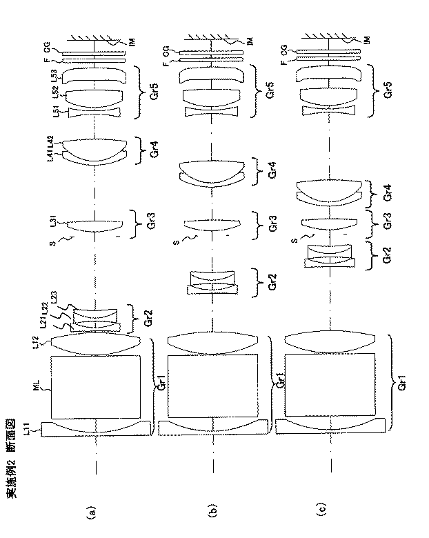
(実施例2)
実施例2にかかるズームレンズのレンズデータを表2に示す。また図5(a)に、実施例2にかかるズームレンズの広角端の断面図を示し、図5(b)に、実施例2にかかるズームレンズの中間の断面図を示し、図5(c)に、実施例2にかかるズームレンズの望遠端の断面図を示す。更に、図6(a)に、実施例2にかかるズームレンズの広角端における球面収差、非点収差、及び歪曲収差の収差図を示し、図6(b)に、実施例2にかかるズームレンズの中間における球面収差、非点収差、及び歪曲収差の収差図を示し、図6(c)に、実施例2にかかるズームレンズの望遠端における球面収差、非点収差、及び歪曲収差の収差図を示す。
(Example 2)
Table 2 shows lens data of the zoom lens according to the second example. FIG. 5A shows a cross-sectional view at the wide-angle end of the zoom lens according to Example 2, and FIG. 5B shows an intermediate cross-sectional view of the zoom lens according to Example 2. FIG. ) Is a sectional view of the zoom lens according to the second embodiment at the telephoto end. Further, FIG. 6A shows aberration diagrams of spherical aberration, astigmatism, and distortion at the wide angle end of the zoom lens according to Example 2, and FIG. 6B shows the zoom lens according to Example 2. FIG. 6C shows aberration diagrams of spherical aberration, astigmatism, and distortion at the telephoto end of the zoom lens according to Example 2. FIG. Indicates.
[表2]
実施例2
f = 4.43 - 9.65 - 21.05 [広角、中間、望遠]
Fno = 2.88 - 4.46 - 5.17 [広角、中間、望遠]
ズーム比 = 4.75
面番号 R(mm) D(mm) Nd νd
1 ∞ 0.500 1.92290 20.9
2 14.549 2.070
3 ∞ 9.300 1.84670 23.8
4 ∞ 0.150
5* 12.661 3.230 1.75500 51.2
6* -22.928 d1
7 -80.000 0.500 1.91080 35.3
8 7.532 0.860
9 -15.754 0.500 1.80420 46.5
10 6.151 1.070 1.94590 18.0
11 23.062 d2
12(絞り) ∞ 0.700
13* 12.915 1.610 1.55330 71.7
14* -20.584 d3
15 13.184 0.600 1.84670 23.8
16 7.470 3.160 1.61880 63.9
17* -24.290 d4
18 -11.082 0.500 2.00070 25.5
19 -142.365 1.000
20 28.705 3.000 1.49700 81.6
21 -10.917 1.000
22* -100.000 2.500 1.53050 55.7
23* -16.658 0.795
24 ∞ 0.500 1.51630 64.2
25 ∞ 0.500
26 ∞ 0.500 1.51630 64.2
27 ∞ 1.700
28 ∞
非球面係数
第5面 第6面
K= 0.00000E+00 K= 0.00000E+00
A4= -0.71663E-04 A4= 0.48465E-04
A6= -0.54715E-06 A6= 0.63347E-06
A8= 0.35783E-07 A8= -0.22432E-07
A10= -0.12621E-08 A10= 0.31321E-09
A12= 0.16418E-10
第13面 第14面
K= 0.00000E+00 K= 0.00000E+00
A4= -0.23792E-03 A4= -0.64795E-04
A6= -0.34374E-04 A6= -0.32471E-04
A8= 0.62731E-05 A8= 0.56569E-05
A10= -0.45509E-06 A10= -0.40111E-06
A12= 0.10222E-07 A12= 0.87180E-08
第17面 第22面
K= 0.00000E+00 K= 0.00000E+00
A4= 0.11659E-03 A4= 0.00000E+00
A6= -0.14486E-06 A6= 0.78403E-04
A8= -0.13363E-06 A8= -0.10282E-04
A10= 0.30440E-08 A10= 0.34927E-06
A12= -0.56837E-08
第23面
K= 0.00000E+00
A4= 0.74639E-03
A6= 0.15838E-03
A8= -0.19355E-04
A10= 0.67645E-06
A12= -0.86821E-08
各ポジションの焦点距離、Fナンバー、群間
f Fno 画角 d1 d2 d3 d4
広角 4.43 2.88 82.5 0.250 10.632 10.149 4.616
中間 9.65 4.46 43.9 5.425 5.457 5.899 8.866
望遠 21.05 5.17 20.9 8.882 2.000 1.932 12.833
レンズ群データ
レンズ群 始面 焦点距離(mm)
1 1 14.22
2 7 -4.66
3 13 14.59
4 15 17.36
5 18 38.60
[Table 2]
Example 2
f = 4.43-9.65-21.05 [Wide angle, Medium, Telephoto]
Fno = 2.88-4.46-5.17 [Wide angle, Medium, Telephoto]
Zoom ratio = 4.75
Surface number R (mm) D (mm) Nd νd
1 ∞ 0.500 1.92290 20.9
2 14.549 2.070
3 ∞ 9.300 1.84670 23.8
4 ∞ 0.150
5 * 12.661 3.230 1.75500 51.2
6 * -22.928 d1
7 -80.000 0.500 1.91080 35.3
8 7.532 0.860
9 -15.754 0.500 1.80420 46.5
10 6.151 1.070 1.94590 18.0
11 23.062 d2
12 (Aperture) ∞ 0.700
13 * 12.915 1.610 1.55330 71.7
14 * -20.584 d3
15 13.184 0.600 1.84670 23.8
16 7.470 3.160 1.61880 63.9
17 * -24.290 d4
18 -11.082 0.500 2.00070 25.5
19 -142.365 1.000
20 28.705 3.000 1.49700 81.6
21 -10.917 1.000
22 * -100.000 2.500 1.53050 55.7
23 * -16.658 0.795
24 ∞ 0.500 1.51630 64.2
25 ∞ 0.500
26 ∞ 0.500 1.51630 64.2
27 ∞ 1.700
28 ∞
Aspheric coefficient
5th surface 6th surface
K = 0.00000E + 00 K = 0.00000E + 00
A4 = -0.71663E-04 A4 = 0.48465E-04
A6 = -0.54715E-06 A6 = 0.63347E-06
A8 = 0.35783E-07 A8 = -0.22432E-07
A10 = -0.12621E-08 A10 = 0.31321E-09
A12 = 0.16418E-10
13th 14th
K = 0.00000E + 00 K = 0.00000E + 00
A4 = -0.23792E-03 A4 = -0.64795E-04
A6 = -0.34374E-04 A6 = -0.32471E-04
A8 = 0.62731E-05 A8 = 0.56569E-05
A10 = -0.45509E-06 A10 = -0.40111E-06
A12 = 0.10222E-07 A12 = 0.87180E-08
17th 22nd
K = 0.00000E + 00 K = 0.00000E + 00
A4 = 0.11659E-03 A4 = 0.00000E + 00
A6 = -0.14486E-06 A6 = 0.78403E-04
A8 = -0.13363E-06 A8 = -0.10282E-04
A10 = 0.30440E-08 A10 = 0.34927E-06
A12 = -0.56837E-08
23rd page
K = 0.00000E + 00
A4 = 0.74639E-03
A6 = 0.15838E-03
A8 = -0.19355E-04
A10 = 0.67645E-06
A12 = -0.86821E-08
Focal length of each position, F number, between groups
f Fno angle of view d 1 d2 d3 d4
Wide angle 4.43 2.88 82. 5 0 .250 10.632 10.149 4.616
Intermediate 9.65 4.46 43. 9 5 .425 5.457 5.899 8.866
Telephoto 21.05 5.17 20. 9 8 .882 2.000 1.932 12.833
Lens group data
Lens group Start surface Focal length (mm)
1 1 14.22
2 7 -4.66
3 13 14.59
4 15 17.36
5 18 38.60
実施例2のズームレンズは、光軸に沿って物体側より順に、変倍時に移動しない正の屈折力を有する第1レンズ群Gr1と、変倍時に光軸に沿って移動する負の屈折力を有する第2レンズ群Gr2と、絞りSを含み変倍時に移動しない正の屈折力を有する第3レンズ群Gr3と、変倍時に光軸に沿って移動する正の屈折力を有する第4レンズ群Gr4と、変倍時に移動しない第5レンズ群Gr5とから構成されている。第5レンズ群Gr5と固体撮像素子の撮像面IMとの間には、光学面に赤外線カットコートを施した赤外線カットフィルタFと、固体撮像素子の撮像面IMを覆うシールガラスCGが配置されている。 The zoom lens of Example 2 includes, in order from the object side along the optical axis, a first lens group Gr1 having a positive refractive power that does not move during zooming, and a negative refractive power that moves along the optical axis during zooming. A second lens group Gr2 having a stop, a third lens group Gr3 including a stop S and having a positive refractive power that does not move during zooming, and a fourth lens having a positive refractive power that moves along the optical axis during zooming It is composed of a group Gr4 and a fifth lens group Gr5 that does not move during zooming. Between the fifth lens group Gr5 and the imaging surface IM of the solid-state imaging device, an infrared cut filter F having an optical surface with an infrared cut coat and a seal glass CG covering the imaging surface IM of the solid-state imaging device are arranged. Yes.
第1レンズ群Gr1は、物体側から順に、負の屈折力を有する第11レンズL11、光軸を屈曲させるための反射部材であるプリズムML、正の屈折力を有する第12レンズL12で構成される。第2レンズ群Gr2は、物体側から順に、正の屈折力を有する第21レンズL21と、負の屈折力を有する第22レンズL22と、正の屈折力を有する第23レンズL23とで構成される。第22レンズL22と第23レンズL23とは互いに接合された接合レンズである。第3レンズ群Gr3は、物体側から順に、絞りSと,正の屈折力を有する第31レンズL31とで構成される。第4レンズ群Gr4は、物体側から順に、負の屈折力を有する第41レンズL41と、正の屈折力を有する第42レンズL42とで構成される。第41レンズL41と第42レンズL42とは互いに接合された接合レンズである。第5レンズ群Gr5は、物体側から順に、負の屈折力を有する第51レンズL51と、正の屈折力を有する第52レンズL52と、第53レンズL53とで構成される。又、合焦に際しては、第4レンズ群Gr4が光軸方向に移動する。更に、手ぶれ補正に際しては、第5レンズ群Gr5の第52レンズL52が、光軸と垂直な方向に変位するようになっている。第53レンズL53はプラスチックから形成されている。 The first lens group Gr1 includes, in order from the object side, an eleventh lens L11 having negative refractive power, a prism ML that is a reflecting member for bending the optical axis, and a twelfth lens L12 having positive refractive power. The The second lens group Gr2 includes, in order from the object side, a twenty-first lens L21 having a positive refractive power, a twenty-second lens L22 having a negative refractive power, and a twenty-third lens L23 having a positive refractive power. The The 22nd lens L22 and the 23rd lens L23 are cemented lenses joined together. The third lens group Gr3 includes, in order from the object side, a stop S and a thirty-first lens L31 having a positive refractive power. The fourth lens group Gr4 includes, in order from the object side, a forty-first lens L41 having a negative refractive power and a forty-second lens L42 having a positive refractive power. The forty-first lens L41 and the forty-second lens L42 are cemented lenses that are cemented with each other. The fifth lens group Gr5 includes, in order from the object side, a 51st lens L51 having negative refractive power, a 52nd lens L52 having positive refractive power, and a 53rd lens L53. In focusing, the fourth lens group Gr4 moves in the optical axis direction. Further, for camera shake correction, the 52nd lens L52 of the fifth lens group Gr5 is displaced in the direction perpendicular to the optical axis. The 53rd lens L53 is made of plastic.
(実施例3)
実施例3にかかるズームレンズのレンズデータを表3に示す。また図7(a)に、実施例3にかかるズームレンズの広角端の断面図を示し、図7(b)に、実施例3にかかるズームレンズの中間の断面図を示し、図7(c)に、実施例3にかかるズームレンズの望遠端の断面図を示す。更に、図8(a)に、実施例3にかかるズームレンズの広角端における球面収差、非点収差、及び歪曲収差の収差図を示し、図8(b)に、実施例3にかかるズームレンズの中間における球面収差、非点収差、及び歪曲収差の収差図を示し、図8(c)に、実施例3にかかるズームレンズの望遠端における球面収差、非点収差、及び歪曲収差の収差図を示す。
(Example 3)
Table 3 shows lens data of the zoom lens according to the third example. FIG. 7A shows a cross-sectional view at the wide-angle end of the zoom lens according to Example 3, and FIG. 7B shows an intermediate cross-sectional view of the zoom lens according to Example 3. FIG. ) Is a cross-sectional view of the zoom lens according to the third embodiment at the telephoto end. Further, FIG. 8A shows aberration diagrams of spherical aberration, astigmatism, and distortion at the wide-angle end of the zoom lens according to Example 3, and FIG. 8B shows the zoom lens according to Example 3. FIG. 8C shows the spherical aberration, astigmatism, and distortion aberration at the telephoto end of the zoom lens according to the third example. Indicates.
[表3]
実施例3
f = 4.42 - 9.66 - 20.98 [広角、中間、望遠]
Fno = 2.88 - 4.49 - 5.01 [広角、中間、望遠]
ズーム比 = 4.75
面番号 R(mm) D(mm) Nd νd
1 ∞ 0.500 2.00270 19.3
2 12.971 1.620
3 ∞ 8.440 1.92120 24.0
4 ∞ 0.150
5* 13.429 3.030 1.80140 45.5
6* -20.415 d1
7 -42.194 0.500 1.91080 35.3
8 7.922 0.870
9 -13.510 0.500 1.77250 49.6
10 7.959 1.030 1.95910 17.5
11 48.639 d2
12(絞り) ∞ 0.700
13* 12.908 1.520 1.55330 71.7
14* -21.908 d3
15 9.128 1.000 2.00270 19.3
16 6.478 0.750
17 8.249 2.890 1.55330 71.7
18* -16.526 d4
19 -14.842 0.500 1.80520 25.5
20 13.805 1.150
21 7.435 2.610 1.49700 81.6
22 -35.082 0.990
23* -123.153 2.990 1.53050 55.7
24* -15.705 0.200
25 ∞ 0.500 1.51630 64.2
26 ∞ 0.500
27 ∞ 0.500 1.51630 64.2
28 ∞ 0.500
29 ∞
非球面係数
第5面 第6面
K= 0.00000E+00 K= 0.00000E+00
A4= -0.11500E-03 A4= -0.14454E-05
A6= 0.12096E-05 A6= 0.25992E-05
A8= -0.16210E-07 A8= -0.81662E-07
A10= -0.58929E-09 A10= 0.10763E-08
A12= 0.16087E-10
第13面 第14面
K= 0.00000E+00 K= 0.00000E+00
A4= -0.10561E-03 A4= -0.13931E-03
A6= -0.14735E-04 A6= -0.17328E-04
A8= 0.16058E-05 A8= 0.20539E-05
A10= -0.64205E-07 A10= -0.99068E-07
A12= -0.11568E-08
第18面 第23面
K= 0.00000E+00 K= 0.00000E+00
A4= 0.31815E-04 A4= -0.35819E-03
A6= -0.32120E-05 A6= -0.66159E-04
A8= -0.13771E-06 A8= 0.46784E-05
A10= -0.56677E-10 A10= -0.24576E-06
A12= 0.42758E-08
第24面
K= 0.00000E+00
A4= 0.68040E-03
A6= -0.89741E-04
A8= 0.77024E-05
A10= -0.39269E-06
A12= 0.66471E-08
各ポジションの焦点距離、Fナンバー、群間
f Fno 画角 d1 d2 d3 d4
広角 4.42 2.88 82.7 0.250 11.334 9.034 5.177
中間 9.66 4.49 43.8 5.957 5.627 5.231 8.980
望遠 20.98 5.01 21.0 9.834 1.750 2.013 12.198
レンズ群データ
レンズ群 始面 焦点距離(mm)
1 1 14.70
2 7 -5.03
3 13 14.91
4 15 16.79
5 18 55.13
[Table 3]
Example 3
f = 4.42-9.66-20.98 [Wide angle, Medium, Telephoto]
Fno = 2.88-4.49-5.01 [Wide angle, Medium, Telephoto]
Zoom ratio = 4.75
Surface number R (mm) D (mm) Nd νd
1 ∞ 0.500 2.00270 19.3
2 12.971 1.620
3 ∞ 8.440 1.92 120 24.0
4 ∞ 0.150
5 * 13.429 3.030 1.80 140 45.5
6 * -20.415 d1
7 -42.194 0.500 1.91080 35.3
8 7.922 0.870
9 -13.510 0.500 1.77250 49.6
10 7.959 1.030 1.95910 17.5
11 48.639 d2
12 (Aperture) ∞ 0.700
13 * 12.908 1.520 1.55330 71.7
14 * -21.908 d3
15 9.128 1.000 2.00270 19.3
16 6.478 0.750
17 8.249 2.890 1.55330 71.7
18 * -16.526 d4
19 -14.842 0.500 1.80520 25.5
20 13.805 1.150
21 7.435 2.610 1.49700 81.6
22 -35.082 0.990
23 * -123.153 2.990 1.53050 55.7
24 * -15.705 0.200
25 ∞ 0.500 1.51630 64.2
26 ∞ 0.500
27 ∞ 0.500 1.51630 64.2
28 ∞ 0.500
29 ∞
Aspheric coefficient
5th surface 6th surface
K = 0.00000E + 00 K = 0.00000E + 00
A4 = -0.11500E-03 A4 = -0.14454E-05
A6 = 0.12096E-05 A6 = 0.25992E-05
A8 = -0.16210E-07 A8 = -0.81662E-07
A10 = -0.58929E-09 A10 = 0.10763E-08
A12 = 0.16087E-10
13th 14th
K = 0.00000E + 00 K = 0.00000E + 00
A4 = -0.10561E-03 A4 = -0.13931E-03
A6 = -0.14735E-04 A6 = -0.17328E-04
A8 = 0.16058E-05 A8 = 0.20539E-05
A10 = -0.64205E-07 A10 = -0.99068E-07
A12 = -0.11568E-08
18th 23rd
K = 0.00000E + 00 K = 0.00000E + 00
A4 = 0.31815E-04 A4 = -0.35819E-03
A6 = -0.32120E-05 A6 = -0.66159E-04
A8 = -0.13771E-06 A8 = 0.46784E-05
A10 = -0.56677E-10 A10 = -0.24576E-06
A12 = 0.42758E-08
24th page
K = 0.00000E + 00
A4 = 0.68040E-03
A6 = -0.89741E-04
A8 = 0.77024E-05
A10 = -0.39269E-06
A12 = 0.66471E-08
Focal length of each position, F number, between groups
f Fno angle of view d 1 d2 d3 d4
Wide angle 4.42 2.88 82. 7 0 .250 11.334 9.034 5.177
Intermediate 9.66 4.49 43. 8 5 .957 5.627 5.231 8.980
Telephoto 20.98 5.01 21. 0 9 .834 1.750 2.013 12.198
Lens group data
Lens group Start surface Focal length (mm)
1 1 14.70
2 7 -5.03
3 13 14.91
4 15 16.79
5 18 55.13
実施例3のズームレンズは、光軸に沿って物体側より順に、変倍時に移動しない正の屈折力を有する第1レンズ群Gr1と、変倍時に光軸に沿って移動する負の屈折力を有する第2レンズ群Gr2と、絞りSを含み変倍時に移動しない正の屈折力を有する第3レンズ群Gr3と、変倍時に光軸に沿って移動する正の屈折力を有する第4レンズ群Gr4と、変倍時に移動しない第5レンズ群Gr5とから構成されている。第5レンズ群Gr5と固体撮像素子の撮像面IMとの間には、光学面に赤外線カットコートを施した赤外線カットフィルタFと、固体撮像素子の撮像面IMを覆うシールガラスCGが配置されている。 The zoom lens of Example 3 includes, in order from the object side along the optical axis, a first lens group Gr1 having a positive refractive power that does not move during zooming, and a negative refractive power that moves along the optical axis during zooming. A second lens group Gr2 having a stop, a third lens group Gr3 including a stop S and having a positive refractive power that does not move during zooming, and a fourth lens having a positive refractive power that moves along the optical axis during zooming It is composed of a group Gr4 and a fifth lens group Gr5 that does not move during zooming. Between the fifth lens group Gr5 and the imaging surface IM of the solid-state imaging device, an infrared cut filter F having an optical surface with an infrared cut coat and a seal glass CG covering the imaging surface IM of the solid-state imaging device are arranged. Yes.
第1レンズ群Gr1は、物体側から順に、負の屈折力を有する第11レンズL11、光軸を屈曲させるための反射部材であるプリズムML、正の屈折力を有する第12レンズL12で構成される。第2レンズ群Gr2は、物体側から順に、正の屈折力を有する第21レンズL21と、負の屈折力を有する第22レンズL22と、正の屈折力を有する第23レンズL23とで構成される。第22レンズL22と第23レンズL23とは互いに接合された接合レンズである。第3レンズ群Gr3は、物体側から順に、絞りSと,正の屈折力を有する第31レンズL31とで構成される。第4レンズ群Gr4は、物体側から順に、負の屈折力を有する第41レンズL41と、正の屈折力を有する第42レンズL42とで構成される。第5レンズ群Gr5は、物体側から順に、負の屈折力を有する第51レンズL51と、正の屈折力を有する第52レンズL52と、第53レンズL53とで構成される。又、合焦に際しては、第4レンズ群Gr4が光軸方向に移動する。更に、手ぶれ補正に際しては、第5レンズ群Gr5の第52レンズL52が、光軸と垂直な方向に変位するようになっている。第53レンズL53はプラスチックから形成されている。 The first lens group Gr1 includes, in order from the object side, an eleventh lens L11 having negative refractive power, a prism ML that is a reflecting member for bending the optical axis, and a twelfth lens L12 having positive refractive power. The The second lens group Gr2 includes, in order from the object side, a twenty-first lens L21 having a positive refractive power, a twenty-second lens L22 having a negative refractive power, and a twenty-third lens L23 having a positive refractive power. The The 22nd lens L22 and the 23rd lens L23 are cemented lenses joined together. The third lens group Gr3 includes, in order from the object side, a stop S and a thirty-first lens L31 having a positive refractive power. The fourth lens group Gr4 includes, in order from the object side, a forty-first lens L41 having a negative refractive power and a forty-second lens L42 having a positive refractive power. The fifth lens group Gr5 includes, in order from the object side, a 51st lens L51 having negative refractive power, a 52nd lens L52 having positive refractive power, and a 53rd lens L53. In focusing, the fourth lens group Gr4 moves in the optical axis direction. Further, for camera shake correction, the 52nd lens L52 of the fifth lens group Gr5 is displaced in the direction perpendicular to the optical axis. The 53rd lens L53 is made of plastic.
(実施例4)
実施例4にかかるズームレンズのレンズデータを表4に示す。また図9(a)に、実施例4にかかるズームレンズの広角端の断面図を示し、図9(b)に、実施例4にかかるズームレンズの中間の断面図を示し、図9(c)に、実施例4にかかるズームレンズの望遠端の断面図を示す。更に、図10(a)に、実施例4にかかるズームレンズの広角端における球面収差、非点収差、及び歪曲収差の収差図を示し、図10(b)に、実施例4にかかるズームレンズの中間における球面収差、非点収差、及び歪曲収差の収差図を示し、図10(c)に、実施例4にかかるズームレンズの望遠端における球面収差、非点収差、及び歪曲収差の収差図を示す。
Example 4
Table 4 shows lens data of the zoom lens according to the fourth example. FIG. 9A shows a cross-sectional view at the wide-angle end of the zoom lens according to Example 4, and FIG. 9B shows an intermediate cross-sectional view of the zoom lens according to Example 4. FIG. ) Is a cross-sectional view of the zoom lens according to the fourth embodiment at the telephoto end. Further, FIG. 10A shows aberration diagrams of spherical aberration, astigmatism, and distortion at the wide angle end of the zoom lens according to Example 4, and FIG. 10B shows the zoom lens according to Example 4. FIG. 10C shows aberration diagrams of spherical aberration, astigmatism, and distortion at the telephoto end of the zoom lens according to Example 4. Indicates.
[表4]
実施例4
f = 4.43 - 9.57 - 21.05 [広角、中間、望遠]
Fno = 2.88 - 4.54 - 5.07 [広角、中間、望遠]
ズーム比 = 4.75
面番号 R(mm) D(mm) Nd νd
1 ∞ 0.500 1.92290 20.9
2 14.250 2.060
3 ∞ 9.450 1.84670 23.8
4 ∞ 0.150
5* 13.358 3.010 1.75500 51.2
6* -24.497 d1
7 -666.266 0.500 1.91080 35.3
8 7.533 0.940
9 -28.966 0.500 1.78590 43.9
10 5.647 1.200 1.95910 17.5
11 16.850 d2
12(絞り) ∞ 0.700
13* 8.977 1.590 1.55330 71.7
14* -73.387 d3
15 9.694 0.600 1.80520 25.5
16 5.641 2.870 1.59200 67.0
17* -33.430 d4
18 -19.522 0.500 1.90320 29.8
19 19.522 0.390
20 8.938 2.580 1.49700 81.6
21 -13.204 1.740
22* -4.620 2.150 1.53050 55.7
23* -5.684 1.360
24 ∞ 0.500 1.51630 64.2
25 ∞ 0.500
26 ∞ 0.500 1.51630 64.2
27 ∞ 1.700
28 ∞
非球面係数
第5面 第6面
K= 0.00000E+00 K= 0.00000E+00
A4= -0.54077E-04 A4= 0.45570E-04
A6= 0.82184E-06 A6= 0.22870E-05
A8= -0.21896E-07 A8= -0.11854E-06
A10= -0.80854E-09 A10= 0.20074E-08
A12= 0.27979E-10
第13面 第14面
K= 0.00000E+00 K= 0.00000E+00
A4= -0.60244E-03 A4= -0.40650E-03
A6= 0.64967E-05 A6= 0.32045E-05
A8= 0.95187E-06 A8= 0.20251E-05
A10= -0.12563E-06 A10= -0.21766E-06
A12= 0.16363E-08 A12= 0.44098E-08
第17面 第22面
K= 0.00000E+00 K= 0.00000E+00
A4= 0.30489E-03 A4= 0.17725E-02
A6= 0.11808E-05 A6= 0.47037E-04
A8= -0.61387E-06 A8= -0.15291E-04
A10= 0.91058E-08 A10= 0.55243E-06
A12= -0.41696E-08
第23面
K= 0.00000E+00
A4= 0.20600E-02
A6= 0.98827E-05
A8= -0.89332E-05
A10= 0.32795E-06
A12= -0.31911E-08
各ポジションの焦点距離、Fナンバー、群間
f Fno 画角 d1 d2 d3 d4
広角 4.43 2.88 82.5 0.260 11.741 8.295 2.381
中間 9.57 4.54 44.2 6.088 5.913 5.027 5.649
望遠 21.05 5.07 20.9 10.251 1.750 2.058 8.618
レンズ群データ
レンズ群 始面 焦点距離(mm)
1 1 15.86
2 7 -5.35
3 13 14.56
4 15 16.11
5 18 -969.79
[Table 4]
Example 4
f = 4.43-9.57-21.05 [Wide-angle, Medium, Telephoto]
Fno = 2.88-4.54-5.07 [Wide angle, Medium, Telephoto]
Zoom ratio = 4.75
Surface number R (mm) D (mm) Nd νd
1 ∞ 0.500 1.92290 20.9
2 14.250 2.060
3 ∞ 9.450 1.84670 23.8
4 ∞ 0.150
5 * 13.358 3.010 1.75500 51.2
6 * -24.497 d1
7 -666.266 0.500 1.91080 35.3
8 7.533 0.940
9 -28.966 0.500 1.78590 43.9
10 5.647 1.200 1.95910 17.5
11 16.850 d2
12 (Aperture) ∞ 0.700
13 * 8.977 1.590 1.55330 71.7
14 * -73.387 d3
15 9.694 0.600 1.80520 25.5
16 5.641 2.870 1.59200 67.0
17 * -33.430 d4
18 -19.522 0.500 1.90320 29.8
19 19.522 0.390
20 8.938 2.580 1.49700 81.6
21 -13.204 1.740
22 * -4.620 2.150 1.53050 55.7
23 * -5.684 1.360
24 ∞ 0.500 1.51630 64.2
25 ∞ 0.500
26 ∞ 0.500 1.51630 64.2
27 ∞ 1.700
28 ∞
Aspheric coefficient
5th surface 6th surface
K = 0.00000E + 00 K = 0.00000E + 00
A4 = -0.54077E-04 A4 = 0.45570E-04
A6 = 0.82184E-06 A6 = 0.22870E-05
A8 = -0.21896E-07 A8 = -0.11854E-06
A10 = -0.80854E-09 A10 = 0.20074E-08
A12 = 0.27979E-10
13th 14th
K = 0.00000E + 00 K = 0.00000E + 00
A4 = -0.60244E-03 A4 = -0.40650E-03
A6 = 0.64967E-05 A6 = 0.32045E-05
A8 = 0.95187E-06 A8 = 0.20251E-05
A10 = -0.12563E-06 A10 = -0.21766E-06
A12 = 0.16363E-08 A12 = 0.44098E-08
17th 22nd
K = 0.00000E + 00 K = 0.00000E + 00
A4 = 0.30489E-03 A4 = 0.17725E-02
A6 = 0.11808E-05 A6 = 0.47037E-04
A8 = -0.61387E-06 A8 = -0.15291E-04
A10 = 0.91058E-08 A10 = 0.55243E-06
A12 = -0.41696E-08
23rd page
K = 0.00000E + 00
A4 = 0.20600E-02
A6 = 0.98827E-05
A8 = -0.89332E-05
A10 = 0.32795E-06
A12 = -0.31911E-08
Focal length of each position, F number, between groups
f Fno angle of view d 1 d2 d3 d4
Wide angle 4.43 2.88 82. 5 0 .260 11.741 8.295 2.381
Intermediate 9.57 4.54 44. 2 6 .088 5.913 5.027 5.649
Telephoto 21.05 5.07 20. 9 1 0.251 1.750 2.058 8.618
Lens group data
Lens group Start surface Focal length (mm)
1 1 15.86
2 7 -5.35
3 13 14.56
4 15 16.11
5 18 -969.79
実施例4のズームレンズは、光軸に沿って物体側より順に、変倍時に移動しない正の屈折力を有する第1レンズ群Gr1と、変倍時に光軸に沿って移動する負の屈折力を有する第2レンズ群Gr2と、絞りSを含み変倍時に移動しない正の屈折力を有する第3レンズ群Gr3と、変倍時に光軸に沿って移動する正の屈折力を有する第4レンズ群Gr4と、変倍時に移動しない第5レンズ群Gr5とから構成されている。第5レンズ群Gr5と固体撮像素子の撮像面IMとの間には、光学面に赤外線カットコートを施した赤外線カットフィルタFと、固体撮像素子の撮像面IMを覆うシールガラスCGが配置されている。 The zoom lens of Example 4 includes, in order from the object side along the optical axis, a first lens group Gr1 having a positive refractive power that does not move during zooming, and a negative refractive power that moves along the optical axis during zooming. A second lens group Gr2 having a stop, a third lens group Gr3 including a stop S and having a positive refractive power that does not move during zooming, and a fourth lens having a positive refractive power that moves along the optical axis during zooming It is composed of a group Gr4 and a fifth lens group Gr5 that does not move during zooming. Between the fifth lens group Gr5 and the imaging surface IM of the solid-state imaging device, an infrared cut filter F having an optical surface with an infrared cut coat and a seal glass CG covering the imaging surface IM of the solid-state imaging device are arranged. Yes.
第1レンズ群Gr1は、物体側から順に、負の屈折力を有する第11レンズL11、光軸を屈曲させるための反射部材であるプリズムML、正の屈折力を有する第12レンズL12で構成される。第2レンズ群Gr2は、物体側から順に、正の屈折力を有する第21レンズL21と、負の屈折力を有する第22レンズL22と、正の屈折力を有する第23レンズL23とで構成される。第22レンズL22と第23レンズL23とは互いに接合された接合レンズである。第3レンズ群Gr3は、物体側から順に、絞りSと,正の屈折力を有する第31レンズL31とで構成される。第4レンズ群Gr4は、物体側から順に、負の屈折力を有する第41レンズL41と、正の屈折力を有する第42レンズL42とで構成される。第41レンズL41と第42レンズL42とは互いに接合された接合レンズである。第5レンズ群Gr5は、物体側から順に、負の屈折力を有する第51レンズL51と、正の屈折力を有する第52レンズL52と、第53レンズL53とで構成される。又、合焦に際しては、第4レンズ群Gr4が光軸方向に移動する。更に、手ぶれ補正に際しては、第5レンズ群Gr5の第52レンズL52が、光軸と垂直な方向に変位するようになっている。第53レンズL53はプラスチックから形成されている。 The first lens group Gr1 includes, in order from the object side, an eleventh lens L11 having negative refractive power, a prism ML that is a reflecting member for bending the optical axis, and a twelfth lens L12 having positive refractive power. The The second lens group Gr2 includes, in order from the object side, a twenty-first lens L21 having a positive refractive power, a twenty-second lens L22 having a negative refractive power, and a twenty-third lens L23 having a positive refractive power. The The 22nd lens L22 and the 23rd lens L23 are cemented lenses joined together. The third lens group Gr3 includes, in order from the object side, a stop S and a thirty-first lens L31 having a positive refractive power. The fourth lens group Gr4 includes, in order from the object side, a forty-first lens L41 having a negative refractive power and a forty-second lens L42 having a positive refractive power. The forty-first lens L41 and the forty-second lens L42 are cemented lenses that are cemented with each other. The fifth lens group Gr5 includes, in order from the object side, a 51st lens L51 having negative refractive power, a 52nd lens L52 having positive refractive power, and a 53rd lens L53. In focusing, the fourth lens group Gr4 moves in the optical axis direction. Further, for camera shake correction, the 52nd lens L52 of the fifth lens group Gr5 is displaced in the direction perpendicular to the optical axis. The 53rd lens L53 is made of plastic.
(実施例5)
実施例5にかかるズームレンズのレンズデータを表5に示す。また図11(a)に、実施例5にかかるズームレンズの広角端の断面図を示し、図11(b)に、実施例5にかかるズームレンズの中間の断面図を示し、図11(c)に、実施例5にかかるズームレンズの望遠端の断面図を示す。更に、図12(a)に、実施例5にかかるズームレンズの広角端における球面収差、非点収差、及び歪曲収差の収差図を示し、図12(b)に、実施例5にかかるズームレンズの中間における球面収差、非点収差、及び歪曲収差の収差図を示し、図12(c)に、実施例5にかかるズームレンズの望遠端における球面収差、非点収差、及び歪曲収差の収差図を示す。
(Example 5)
Table 5 shows lens data of the zoom lens according to the fifth example. FIG. 11A shows a cross-sectional view of the zoom lens according to the fifth embodiment at the wide-angle end, and FIG. 11B shows an intermediate cross-sectional view of the zoom lens according to the fifth embodiment. ) Is a cross-sectional view of the zoom lens according to the fifth embodiment at the telephoto end. Further, FIG. 12A shows aberration diagrams of spherical aberration, astigmatism, and distortion at the wide-angle end of the zoom lens according to Example 5, and FIG. 12B shows the zoom lens according to Example 5. FIG. 12C shows aberration diagrams of spherical aberration, astigmatism, and distortion at the telephoto end of the zoom lens according to Example 5. FIG. Indicates.
[表5]
実施例5
f = 4.43 - 9.66 - 21.03 [広角、中間、望遠]
Fno = 2.88 - 4.37 - 5.07 [広角、中間、望遠]
ズーム比 = 4.75
面番号 R(mm) D(mm) Nd νd
1 ∞ 0.500 1.92290 20.9
2 11.606 2.100
3 ∞ 8.790 1.84670 23.8
4 ∞ 0.150
5* 15.473 3.330 1.76800 49.2
6* -19.939 d1
7 -103.607 0.500 1.91080 35.3
8 9.973 0.830
9 -35.680 0.500 1.77250 49.6
10 6.317 1.080 1.95910 17.5
11 14.172 d2
12(絞り) ∞ 0.700
13* 10.258 1.650 1.55330 71.7
14* -57.105 d3
15 9.881 0.600 1.80520 25.5
16 6.033 3.280 1.58700 59.6
17* -28.339 d4
18 -16.333 0.500 1.84670 23.8
19 12.160 0.558
20 8.167 2.790 1.49700 81.6
21 -200.830 1.400
22* -151.308 2.000 1.53050 55.7
23* -14.472 0.270
24 ∞ 0.500 1.51630 64.2
25 ∞ 0.500
26 ∞ 0.500 1.51630 64.2
27 ∞ 1.700
28 ∞
非球面係数
第5面 第6面
K= 0.00000E+00 K= 0.00000E+00
A4= -0.61361E-04 A4= 0.16914E-04
A6= -0.37026E-06 A6= 0.29492E-06
A8= 0.19963E-07 A8= -0.64713E-08
A10= -0.46467E-09 A10= 0.21017E-09
A12= 0.71592E-11
第13面 第14面
K= -0.17400E+01 K= 0.00000E+00
A4= 0.33969E-04 A4= 0.14930E-04
A6= -0.45322E-05 A6= -0.58739E-05
A8= 0.17048E-05 A8= 0.20215E-05
A10= -0.91175E-07 A10= -0.11848E-06
A12= 0.24209E-08 A12= 0.33732E-08
第17面 第22面
K= 0.00000E+00 K= 0.00000E+00
A4= 0.20420E-03 A4= -0.21865E-02
A6= 0.13787E-05 A6= 0.99411E-04
A8= -0.28296E-06 A8= -0.46531E-05
A10= 0.63403E-08 A10= -0.40166E-06
A12= 0.16630E-07
第23面
K= 0.20520E+01
A4= -0.20933E-02
A6= 0.24729E-03
A8= -0.16872E-04
A10= 0.35922E-06
A12= -0.10545E-08
各ポジションの焦点距離、Fナンバー、群間
f Fno 画角 d1 d2 d3 d4
広角 4.43 2.88 82.6 0.250 12.863 9.200 3.919
中間 9.66 4.37 43.8 6.993 6.120 5.719 7.400
望遠 21.03 5.07 20.9 11.363 1.750 1.915 11.204
レンズ群データ
レンズ群 始面 焦点距離(mm)
1 1 17.26
2 7 -5.88
3 13 15.85
4 15 15.51
5 18 -111.19
[Table 5]
Example 5
f = 4.43-9.66-21.03 [wide angle, medium, telephoto]
Fno = 2.88-4.37-5.07 [Wide angle, Medium, Telephoto]
Zoom ratio = 4.75
Surface number R (mm) D (mm) Nd νd
1 ∞ 0.500 1.92290 20.9
2 11.606 2.100
3 ∞ 8.790 1.84670 23.8
4 ∞ 0.150
5 * 15.473 3.330 1.76800 49.2
6 * -19.939 d1
7 -103.607 0.500 1.91080 35.3
8 9.973 0.830
9 -35.680 0.500 1.77250 49.6
10 6.317 1.080 1.95910 17.5
11 14.172 d2
12 (Aperture) ∞ 0.700
13 * 10.258 1.650 1.55330 71.7
14 * -57.105 d3
15 9.881 0.600 1.80520 25.5
16 6.033 3.280 1.58700 59.6
17 * -28.339 d4
18 -16.333 0.500 1.84670 23.8
19 12.160 0.558
20 8.167 2.790 1.49700 81.6
21 -200.830 1.400
22 * -151.308 2.000 1.53050 55.7
23 * -14.472 0.270
24 ∞ 0.500 1.51630 64.2
25 ∞ 0.500
26 ∞ 0.500 1.51630 64.2
27 ∞ 1.700
28 ∞
Aspheric coefficient
5th surface 6th surface
K = 0.00000E + 00 K = 0.00000E + 00
A4 = -0.61361E-04 A4 = 0.16914E-04
A6 = -0.37026E-06 A6 = 0.29492E-06
A8 = 0.19963E-07 A8 = -0.64713E-08
A10 = -0.46467E-09 A10 = 0.21017E-09
A12 = 0.71592E-11
13th 14th
K = -0.17400E + 01 K = 0.00000E + 00
A4 = 0.33969E-04 A4 = 0.14930E-04
A6 = -0.45322E-05 A6 = -0.58739E-05
A8 = 0.17048E-05 A8 = 0.20215E-05
A10 = -0.91175E-07 A10 = -0.11848E-06
A12 = 0.24209E-08 A12 = 0.33732E-08
17th 22nd
K = 0.00000E + 00 K = 0.00000E + 00
A4 = 0.20420E-03 A4 = -0.21865E-02
A6 = 0.13787E-05 A6 = 0.99411E-04
A8 = -0.28296E-06 A8 = -0.46531E-05
A10 = 0.63403E-08 A10 = -0.40166E-06
A12 = 0.16630E-07
23rd page
K = 0.20520E + 01
A4 = -0.20933E-02
A6 = 0.24729E-03
A8 = -0.16872E-04
A10 = 0.35922E-06
A12 = -0.10545E-08
Focal length of each position, F number, between groups
f Fno angle of view d 1 d2 d3 d4
Wide angle 4.43 2.88 82. 6 0 .250 12.863 9.200 3.919
Intermediate 9.66 4.37 43. 8 6 .993 6.120 5.719 7.400
Telephoto 21.03 5.07 20. 9 1 1.363 1.750 1.915 11.204
Lens group data
Lens group Start surface Focal length (mm)
1 1 17.26
2 7 -5.88
3 13 15.85
4 15 15.51
5 18 -111.19
実施例5のズームレンズは、光軸に沿って物体側より順に、変倍時に移動しない正の屈折力を有する第1レンズ群Gr1と、変倍時に光軸に沿って移動する負の屈折力を有する第2レンズ群Gr2と、絞りSを含み変倍時に移動しない正の屈折力を有する第3レンズ群Gr3と、変倍時に光軸に沿って移動する正の屈折力を有する第4レンズ群Gr4と、変倍時に移動しない第5レンズ群Gr5とから構成されている。第5レンズ群Gr5と固体撮像素子の撮像面IMとの間には、光学面に赤外線カットコートを施した赤外線カットフィルタFと、固体撮像素子の撮像面IMを覆うシールガラスCGが配置されている。 The zoom lens of Example 5 includes, in order from the object side along the optical axis, a first lens group Gr1 having a positive refractive power that does not move during zooming, and a negative refractive power that moves along the optical axis during zooming. A second lens group Gr2 having a stop, a third lens group Gr3 including a stop S and having a positive refractive power that does not move during zooming, and a fourth lens having a positive refractive power that moves along the optical axis during zooming It is composed of a group Gr4 and a fifth lens group Gr5 that does not move during zooming. Between the fifth lens group Gr5 and the imaging surface IM of the solid-state imaging device, an infrared cut filter F having an optical surface with an infrared cut coat and a seal glass CG covering the imaging surface IM of the solid-state imaging device are arranged. Yes.
第1レンズ群Gr1は、物体側から順に、負の屈折力を有する第11レンズL11、光軸を屈曲させるための反射部材であるプリズムML、正の屈折力を有する第12レンズL12で構成される。第2レンズ群Gr2は、物体側から順に、正の屈折力を有する第21レンズL21と、負の屈折力を有する第22レンズL22と、正の屈折力を有する第23レンズL23とで構成される。第22レンズL22と第23レンズL23とは互いに接合された接合レンズである。第3レンズ群Gr3は、物体側から順に、絞りSと,正の屈折力を有する第31レンズL31とで構成される。第4レンズ群Gr4は、物体側から順に、負の屈折力を有する第41レンズL41と、正の屈折力を有する第42レンズL42とで構成される。第41レンズL41と第42レンズL42とは互いに接合された接合レンズである。第5レンズ群Gr5は、物体側から順に、負の屈折力を有する第51レンズL51と、正の屈折力を有する第52レンズL52と、第53レンズL53とで構成される。又、合焦に際しては、第4レンズ群Gr4が光軸方向に移動する。更に、手ぶれ補正に際しては、第5レンズ群Gr5の第52レンズL52が、光軸と垂直な方向に変位するようになっている。第53レンズL53はプラスチックから形成されている。 The first lens group Gr1 includes, in order from the object side, an eleventh lens L11 having negative refractive power, a prism ML that is a reflecting member for bending the optical axis, and a twelfth lens L12 having positive refractive power. The The second lens group Gr2 includes, in order from the object side, a twenty-first lens L21 having a positive refractive power, a twenty-second lens L22 having a negative refractive power, and a twenty-third lens L23 having a positive refractive power. The The 22nd lens L22 and the 23rd lens L23 are cemented lenses joined together. The third lens group Gr3 includes, in order from the object side, a stop S and a thirty-first lens L31 having a positive refractive power. The fourth lens group Gr4 includes, in order from the object side, a forty-first lens L41 having a negative refractive power and a forty-second lens L42 having a positive refractive power. The forty-first lens L41 and the forty-second lens L42 are cemented lenses that are cemented with each other. The fifth lens group Gr5 includes, in order from the object side, a 51st lens L51 having negative refractive power, a 52nd lens L52 having positive refractive power, and a 53rd lens L53. In focusing, the fourth lens group Gr4 moves in the optical axis direction. Further, for camera shake correction, the 52nd lens L52 of the fifth lens group Gr5 is displaced in the direction perpendicular to the optical axis. The 53rd lens L53 is made of plastic.
上述した実施例に対応する式と、式を計算するための各数値を、表6,7にまとめて示す。 Tables 6 and 7 collectively show equations corresponding to the above-described embodiments and numerical values for calculating the equations.
また、本発明は、明細書に記載の実施例に限定されるものではなく、他の実施例・変形例を含むことは、本明細書に記載された実施例や思想から本分野の当業者にとって明らかである。例えば、実質的に屈折力を持たないダミーレンズを更に付与した場合でも本発明の適用範囲内である。 Further, the present invention is not limited to the embodiments described in the specification, and it is understood that other embodiments and modifications are included in the art from the embodiments and ideas described in the present specification. It is obvious to For example, even when a dummy lens having substantially no refractive power is further provided, it is within the scope of application of the present invention.
10 撮像装置
12 筐体
12a 開口
32 ディスプレイ
34 レリーズボタン
36 電源スイッチ
38 ズーム操作スイッチ
40 操作スイッチ
50 鏡胴
F 赤外線カットフィルタ
Gr1〜Gr5 レンズ群
ML プリズム(反射部材)
S 絞り
CG シールガラス
IM 固体撮像素子
DESCRIPTION OF
S Aperture CG Seal glass IM Solid-state image sensor
Claims (14)
前記第1レンズ群は光軸を屈曲させるための反射部材を有し、
前記第4レンズ群は物体側から順に、負の屈折力を有する第41レンズと、正の屈折力を有する第42レンズで構成され、
前記第5レンズ群は物体側から順に、負の屈折力を有する第51レンズ、正の屈折力を有する第52レンズ、第53レンズで構成され、以下の条件式を満足することを特徴とするズームレンズ。
−1.50 < f2/fw < −1.00 (1)
3.30 < f4/fw < 4.30 (2)
0.3 < |β4T/β4W| < 1.0 (3)
1.0 < d2wt/d4wt <1.7 (9)
但し、
f2:前記第2レンズ群の焦点距離(mm)
f4:前記第4レンズ群の焦点距離(mm)
fw:広角端での全系の合成焦点距離(mm)
β4W:前記第4レンズ群の広角端における横倍率
β4T:前記第4レンズ群の望遠端における横倍率
d2wt:変倍に際して前記第2レンズ群が広角端から望遠端まで移動する距離(mm)
d4wt:変倍に際して前記第4レンズ群が広角端から望遠端まで移動する距離(mm) A first lens group arranged in order from the object side and having a positive refractive power that does not move at the time of zooming; a second lens group having a negative refractive power that moves along the optical axis at the time of zooming; and a stop A third lens group having a positive refractive power that does not move at the time of zooming, a fourth lens group having a positive refractive power that moves along the optical axis at the time of zooming, and a fifth lens group that does not move at the time of zooming. In the configured zoom lens, the first lens group has a reflecting member for bending the optical axis,
The fourth lens group includes, in order from the object side, a forty-first lens having negative refractive power and a forty-second lens having positive refractive power,
The fifth lens group includes, in order from the object side, a 51st lens having negative refractive power, a 52nd lens having positive refractive power, and a 53rd lens, and satisfies the following conditional expression: Zoom lens.
−1.50 <f2 / fw <−1.00 (1)
3.30 <f4 / fw <4.30 (2)
0.3 <| β4T / β4W | <1.0 (3)
1.0 <d2wt / d4wt <1.7 (9)
However,
f2: Focal length (mm) of the second lens group
f4: Focal length (mm) of the fourth lens group
fw: Total focal length of the entire system at the wide-angle end (mm)
β4W: lateral magnification at the wide-angle end of the fourth lens group β4T: lateral magnification at the telephoto end of the fourth lens group
d2 wt: Distance (mm) by which the second lens unit moves from the wide-angle end to the telephoto end during zooming
d4 wt: Distance (mm) by which the fourth lens group moves from the wide-angle end to the telephoto end during zooming
5 < dL1PR/(2Y/fw) <8 (4)
但し、
dL1PR:前記第1レンズの物体側の頂点から前記反射部材の最も像側の部位までの光軸上の距離(mm)
2Y:前記ズームレンズにより画像を形成される固体撮像素子の撮像面対角長(mm) The zoom lens according to claim 1, wherein the following conditional expression is satisfied.
5 <dL1PR / (2Y / fw) <8 (4)
However,
dL1PR: distance (mm) on the optical axis from the object-side apex of the first lens to the most image-side portion of the reflecting member
2Y: diagonal length (mm) of the imaging surface of the solid-state imaging device on which an image is formed by the zoom lens
1.0 < f1/(fw×Fnow) < 1.5 (5)
f1:前記第1レンズ群の焦点距離(mm)
Fnow:広角端でのFナンバー The zoom lens according to any one of claims 1 to 3, wherein the following conditional expression is satisfied.
1.0 <f1 / (fw × Fnow) <1.5 (5)
f1: Focal length (mm) of the first lens group
Fnow: F number at the wide-angle end
2.0 < |β2T/β2W| < 3.0 (6)
β2W:前記第2レンズ群の広角端の横倍率
β2T:前記第2レンズ群の望遠端の横倍率 The zoom lens according to any one of claims 1 to 4, wherein the following conditional expression is satisfied.
2.0 <| β2T / β2W | <3.0 (6)
β2W: lateral magnification at the wide-angle end of the second lens group β2T: lateral magnification at the telephoto end of the second lens group
0.3 < (1−β52T)×β53T <0.9 (7)
但し、
β52T:前記第5レンズ群の第52レンズの望遠端における横倍率
β53T:前記第5レンズ群の第53レンズの望遠端における横倍率 The 52nd lens of the fifth lens group is an image blur correction lens that corrects image blur on the image plane by being displaced in a direction perpendicular to the optical axis, and satisfies the following conditional expression: The zoom lens according to any one of claims 1 to 5.
0.3 <(1-β52T) × β53T <0.9 (7)
However,
β52T: lateral magnification at the telephoto end of the 52nd lens in the fifth lens group β53T: lateral magnification at the telephoto end of the 53rd lens in the fifth lens group
0.3 < |fp/ft| (8)
fp:前記第53レンズの焦点距離(mm)
ft:望遠端での全系の合成焦点距離(mm) The zoom lens according to claim 1, wherein the following conditional expression is satisfied.
0.3 <| fp / ft | (8)
fp: focal length of the 53rd lens (mm)
ft: Total focal length of the entire system at the telephoto end (mm)
Priority Applications (2)
| Application Number | Priority Date | Filing Date | Title |
|---|---|---|---|
| JP2013252797A JP6323742B2 (en) | 2013-12-06 | 2013-12-06 | Zoom lens, lens unit, and imaging apparatus |
| CN201410737277.2A CN104698575B (en) | 2013-12-06 | 2014-12-05 | Zoom lens, lens unit and camera device |
Applications Claiming Priority (1)
| Application Number | Priority Date | Filing Date | Title |
|---|---|---|---|
| JP2013252797A JP6323742B2 (en) | 2013-12-06 | 2013-12-06 | Zoom lens, lens unit, and imaging apparatus |
Publications (2)
| Publication Number | Publication Date |
|---|---|
| JP2015111185A JP2015111185A (en) | 2015-06-18 |
| JP6323742B2 true JP6323742B2 (en) | 2018-05-16 |
Family
ID=53345883
Family Applications (1)
| Application Number | Title | Priority Date | Filing Date |
|---|---|---|---|
| JP2013252797A Active JP6323742B2 (en) | 2013-12-06 | 2013-12-06 | Zoom lens, lens unit, and imaging apparatus |
Country Status (2)
| Country | Link |
|---|---|
| JP (1) | JP6323742B2 (en) |
| CN (1) | CN104698575B (en) |
Families Citing this family (4)
| Publication number | Priority date | Publication date | Assignee | Title |
|---|---|---|---|---|
| JP6685950B2 (en) * | 2017-02-17 | 2020-04-22 | 富士フイルム株式会社 | Zoom lens and imaging device |
| JP2022013958A (en) * | 2018-11-01 | 2022-01-19 | 株式会社ニコン | Relay optical system and telescope having relay optical system |
| JP7433875B2 (en) | 2019-12-11 | 2024-02-20 | キヤノン株式会社 | Optical system and imaging device |
| CN111897115B (en) * | 2020-07-31 | 2021-07-27 | 中国科学院西安光学精密机械研究所 | Continuous zooming optical system with heat dissipation and wide pressure adaptability |
Family Cites Families (7)
| Publication number | Priority date | Publication date | Assignee | Title |
|---|---|---|---|---|
| JP3288422B2 (en) * | 1992-04-14 | 2002-06-04 | オリンパス光学工業株式会社 | High zoom lens |
| JP2008083125A (en) * | 2006-09-26 | 2008-04-10 | Olympus Imaging Corp | Zoom lens and imaging apparatus using the same |
| JP4352347B2 (en) * | 2007-08-22 | 2009-10-28 | ソニー株式会社 | Zoom lens and imaging device |
| JP2010008679A (en) * | 2008-06-26 | 2010-01-14 | Sony Corp | Zoom lens and imaging apparatus |
| WO2012090757A1 (en) * | 2010-12-27 | 2012-07-05 | コニカミノルタオプト株式会社 | Zoom lens and image capture device |
| JP2013044757A (en) * | 2011-08-19 | 2013-03-04 | Konica Minolta Advanced Layers Inc | Zoom lens and imaging apparatus |
| JP6153310B2 (en) * | 2012-10-30 | 2017-06-28 | キヤノン株式会社 | Zoom lens and imaging apparatus having the same |
-
2013
- 2013-12-06 JP JP2013252797A patent/JP6323742B2/en active Active
-
2014
- 2014-12-05 CN CN201410737277.2A patent/CN104698575B/en not_active Expired - Fee Related
Also Published As
| Publication number | Publication date |
|---|---|
| CN104698575A (en) | 2015-06-10 |
| JP2015111185A (en) | 2015-06-18 |
| CN104698575B (en) | 2017-11-10 |
| CN104698575A9 (en) | 2017-06-09 |
Similar Documents
| Publication | Publication Date | Title |
|---|---|---|
| US7688519B2 (en) | Zoom lens and image pickup apparatus including the same | |
| JP4982786B2 (en) | Imaging optical system and imaging apparatus | |
| JP6300507B2 (en) | Zoom lens and zoom lens apparatus having the same | |
| JP5273184B2 (en) | Zoom lens, optical device, and zoom lens manufacturing method | |
| JP4950608B2 (en) | Zoom lens and imaging apparatus having the same | |
| JP5309553B2 (en) | Zoom lens and optical apparatus provided with the zoom lens | |
| EP2135127A1 (en) | Zoom lens system and camera including the same | |
| JP2012212106A (en) | Zoom lens system, interchangeable lens apparatus, and camera system | |
| JP2011197472A (en) | Zoom lens system, interchangeable lens device, and camera system | |
| JP2009014766A (en) | Variable power optical system, optical apparatus, and power changing method for variable power optical system | |
| JP5895497B2 (en) | OPTICAL SYSTEM, IMAGING DEVICE, AND OPTICAL SYSTEM MANUFACTURING METHOD | |
| JP2007233045A (en) | Zoom lens and imaging device | |
| JP2013218299A (en) | Zoom lens system, imaging device, and camera | |
| JP5599022B2 (en) | Zoom lens and imaging apparatus having the same | |
| JP2009139917A (en) | Zoom lens and imaging apparatus | |
| JP6323742B2 (en) | Zoom lens, lens unit, and imaging apparatus | |
| JP4914097B2 (en) | Zoom lens and imaging apparatus having the same | |
| JP2015102810A (en) | Image formation lens system and imaging device including the same | |
| JP2010107566A (en) | Imaging apparatus | |
| JP2013190485A (en) | Zoom lens and imaging apparatus using the same | |
| US6661584B2 (en) | Zoom lens and camera having the zoom lens | |
| JP5750640B2 (en) | Zoom lens and imaging apparatus including the same | |
| JP2011059597A (en) | Variable power optical system and imaging apparatus including the same | |
| JP2007240875A (en) | Zoom lens, camera, and focusing method of the zoom lens | |
| JP5558254B2 (en) | Optical device |
Legal Events
| Date | Code | Title | Description |
|---|---|---|---|
| A621 | Written request for application examination |
Free format text: JAPANESE INTERMEDIATE CODE: A621 Effective date: 20160328 |
|
| A977 | Report on retrieval |
Free format text: JAPANESE INTERMEDIATE CODE: A971007 Effective date: 20170216 |
|
| A131 | Notification of reasons for refusal |
Free format text: JAPANESE INTERMEDIATE CODE: A131 Effective date: 20170310 |
|
| A521 | Written amendment |
Free format text: JAPANESE INTERMEDIATE CODE: A523 Effective date: 20170502 |
|
| A131 | Notification of reasons for refusal |
Free format text: JAPANESE INTERMEDIATE CODE: A131 Effective date: 20170925 |
|
| A521 | Written amendment |
Free format text: JAPANESE INTERMEDIATE CODE: A523 Effective date: 20171115 |
|
| TRDD | Decision of grant or rejection written | ||
| A01 | Written decision to grant a patent or to grant a registration (utility model) |
Free format text: JAPANESE INTERMEDIATE CODE: A01 Effective date: 20180316 |
|
| A61 | First payment of annual fees (during grant procedure) |
Free format text: JAPANESE INTERMEDIATE CODE: A61 Effective date: 20180329 |
|
| R150 | Certificate of patent or registration of utility model |
Ref document number: 6323742 Country of ref document: JP Free format text: JAPANESE INTERMEDIATE CODE: R150 |