JP6323552B2 - Target detection device - Google Patents
Target detection device Download PDFInfo
- Publication number
- JP6323552B2 JP6323552B2 JP2016527624A JP2016527624A JP6323552B2 JP 6323552 B2 JP6323552 B2 JP 6323552B2 JP 2016527624 A JP2016527624 A JP 2016527624A JP 2016527624 A JP2016527624 A JP 2016527624A JP 6323552 B2 JP6323552 B2 JP 6323552B2
- Authority
- JP
- Japan
- Prior art keywords
- unit
- transmission
- level
- wave
- distance
- Prior art date
- Legal status (The legal status is an assumption and is not a legal conclusion. Google has not performed a legal analysis and makes no representation as to the accuracy of the status listed.)
- Active
Links
- 238000001514 detection method Methods 0.000 title claims description 67
- 230000005540 biological transmission Effects 0.000 claims description 137
- 238000005457 optimization Methods 0.000 claims description 11
- 230000015572 biosynthetic process Effects 0.000 claims 2
- 238000000034 method Methods 0.000 description 25
- 238000009795 derivation Methods 0.000 description 19
- 230000010354 integration Effects 0.000 description 16
- 230000006870 function Effects 0.000 description 15
- 238000004364 calculation method Methods 0.000 description 9
- 238000004891 communication Methods 0.000 description 9
- 238000010586 diagram Methods 0.000 description 6
- XLYOFNOQVPJJNP-UHFFFAOYSA-N water Substances O XLYOFNOQVPJJNP-UHFFFAOYSA-N 0.000 description 6
- 230000000694 effects Effects 0.000 description 2
- 230000004044 response Effects 0.000 description 2
- 238000007792 addition Methods 0.000 description 1
- 230000007423 decrease Effects 0.000 description 1
- 230000002452 interceptive effect Effects 0.000 description 1
- 239000004973 liquid crystal related substance Substances 0.000 description 1
- 238000012986 modification Methods 0.000 description 1
- 230000004048 modification Effects 0.000 description 1
- 230000002093 peripheral effect Effects 0.000 description 1
- 239000013535 sea water Substances 0.000 description 1
Images


Classifications
-
- G—PHYSICS
- G01—MEASURING; TESTING
- G01S—RADIO DIRECTION-FINDING; RADIO NAVIGATION; DETERMINING DISTANCE OR VELOCITY BY USE OF RADIO WAVES; LOCATING OR PRESENCE-DETECTING BY USE OF THE REFLECTION OR RERADIATION OF RADIO WAVES; ANALOGOUS ARRANGEMENTS USING OTHER WAVES
- G01S7/00—Details of systems according to groups G01S13/00, G01S15/00, G01S17/00
- G01S7/52—Details of systems according to groups G01S13/00, G01S15/00, G01S17/00 of systems according to group G01S15/00
- G01S7/523—Details of pulse systems
- G01S7/526—Receivers
-
- G—PHYSICS
- G01—MEASURING; TESTING
- G01S—RADIO DIRECTION-FINDING; RADIO NAVIGATION; DETERMINING DISTANCE OR VELOCITY BY USE OF RADIO WAVES; LOCATING OR PRESENCE-DETECTING BY USE OF THE REFLECTION OR RERADIATION OF RADIO WAVES; ANALOGOUS ARRANGEMENTS USING OTHER WAVES
- G01S15/00—Systems using the reflection or reradiation of acoustic waves, e.g. sonar systems
- G01S15/88—Sonar systems specially adapted for specific applications
-
- G—PHYSICS
- G01—MEASURING; TESTING
- G01S—RADIO DIRECTION-FINDING; RADIO NAVIGATION; DETERMINING DISTANCE OR VELOCITY BY USE OF RADIO WAVES; LOCATING OR PRESENCE-DETECTING BY USE OF THE REFLECTION OR RERADIATION OF RADIO WAVES; ANALOGOUS ARRANGEMENTS USING OTHER WAVES
- G01S7/00—Details of systems according to groups G01S13/00, G01S15/00, G01S17/00
- G01S7/52—Details of systems according to groups G01S13/00, G01S15/00, G01S17/00 of systems according to group G01S15/00
- G01S7/523—Details of pulse systems
- G01S7/524—Transmitters
Landscapes
- Engineering & Computer Science (AREA)
- Radar, Positioning & Navigation (AREA)
- Remote Sensing (AREA)
- Physics & Mathematics (AREA)
- Computer Networks & Wireless Communication (AREA)
- General Physics & Mathematics (AREA)
- Acoustics & Sound (AREA)
- Measurement Of Velocity Or Position Using Acoustic Or Ultrasonic Waves (AREA)
Description
本発明は、目標検出装置、目標検出方法、およびプログラムに関する。 The present invention relates to a target detection device, a target detection method, and a program.
ソーナー装置、レーダー装置、ライダー装置など、音波、電波、光波などの波動を送信し、目標からの反射波を受信して目標を検出する装置が、各種提案ないし実用化されている。また、この種の目標検出装置において、干渉する信号(残響など)による影響を軽減する手法が各種提案ないし実用化されている。 Various proposals and practical applications have been made on devices that detect waves by transmitting waves such as sound waves, radio waves, and light waves and receiving reflected waves from targets, such as sonar devices, radar devices, and rider devices. In this type of target detection apparatus, various methods for reducing the influence of interfering signals (such as reverberation) have been proposed or put into practical use.
例えば、移動している目標物を検出するアクティブソーナー装置において、ドップラー効果により目標からの反射波と残響の周波数が異なることを利用して、残響を除去することが本発明に関連する第1の関連技術として提案されている(例えば特許文献1参照)。 For example, in an active sonar device that detects a moving target, the reverberation is removed by utilizing the fact that the reflected wave from the target and the reverberation frequency are different due to the Doppler effect. It has been proposed as a related technique (see, for example, Patent Document 1).
また、静止している目標物を検出するアクティブソーナー装置において、可変帯域阻止フィルタの設定周波数を時間的に変化させることにより、水底または水面からの残響と目標からの反射波とを分離することが本発明に関連する第2の関連技術として提案されている(例えば特許文献2参照)。 Also, in an active sonar device that detects a stationary target, the reverberation from the bottom or the water surface and the reflected wave from the target can be separated from each other by changing the set frequency of the variable band rejection filter over time. It has been proposed as a second related technique related to the present invention (see, for example, Patent Document 2).
また、送信器と受信器とを一定距離だけ離間して配置したバイスタティックまたはマルチスタティックと呼ばれるアクティブソーナー装置において、音響信号を連続的に送信する送信器と、物体から反射された上記音響信号の反射信号と上記送信器からの直接的音響信号とを受信する受信器とを備え、上記受信器が上記送信器が送信を行う間に、上記直接的音響信号と上記物体から受信した上記反射信号とを処理により弁別することが本発明に関連する第3の関連技術として提案されている(例えば特許文献3、4参照)。
Also, in an active sonar device called bistatic or multistatic where a transmitter and a receiver are spaced apart from each other by a certain distance, a transmitter that continuously transmits an acoustic signal, and the acoustic signal reflected from an object A receiver for receiving a reflected signal and a direct acoustic signal from the transmitter, and the reflected signal received from the direct acoustic signal and the object while the receiver is transmitting. Has been proposed as a third related technique related to the present invention (see, for example,
また、アクティブソーナー装置において、送信器からの音響信号の影響を軽減するために送信器と受信器とを所定の距離だけ離間して配置することが本発明に関連する第4の関連技術として提案されている(例えば特許文献5参照)。 Further, in the active sonar device, in order to reduce the influence of the acoustic signal from the transmitter, it is proposed as a fourth related technique related to the present invention that the transmitter and the receiver are spaced apart by a predetermined distance. (See, for example, Patent Document 5).
ところで、波動を送信し目標からの反射波を受信して目標を検出する装置の検出性能に影響する干渉信号としては、水底または水面からの残響や送信器からの直接的音響信号以外に、波動が伝搬する媒質による散乱によって受信部に到達する散乱波が考えられる。このような散乱波による影響の程度は、送信部と受信部との間の距離、送信部および受信部のビーム形状やビームの向きなどが関係すると考えられるけれども、そのような送信部と受信部の仕様がどのように影響するかを理論的に解析した文献は知られていない。そのため、この種の散乱波による影響を軽減するように送信部と受信部の仕様を制御することは困難であった。 By the way, as an interference signal that affects the detection performance of a device that detects a target by transmitting a wave and receiving a reflected wave from the target, in addition to reverberation from the bottom or water surface or a direct acoustic signal from a transmitter, a wave A scattered wave that reaches the receiver due to scattering by the medium through which the light propagates can be considered. The degree of influence of such scattered waves is considered to be related to the distance between the transmission unit and the reception unit, the beam shape of the transmission unit and the reception unit, the direction of the beam, and the like. There are no known literatures that theoretically analyze how the specifications of the system affect. Therefore, it has been difficult to control the specifications of the transmission unit and the reception unit so as to reduce the influence of this type of scattered wave.
本発明の目的は、上述したような課題、すなわち、波動が伝搬する媒質による散乱によって受信部に到達する散乱波の影響を軽減するように送信部と受信部の仕様を制御することは困難である、という課題を解決する目標検出装置を提供することにある。 The object of the present invention is to control the specifications of the transmission unit and the reception unit so as to reduce the problem as described above, that is, the influence of scattered waves that reach the reception unit due to scattering by the medium through which the wave propagates. An object of the present invention is to provide a target detection apparatus that solves the problem of being.
本発明の第1の観点に係る目標検出装置は、
波動を送信する送信部と、
検出対象物から反射された上記波動の反射波を受信する受信部と、
上記受信部の出力に基づいて上記検出対象物を検出する検出部と、
上記波動が伝搬する媒質による散乱によって上記受信部に到達する散乱波の影響を軽減するための関係式を満足するように上記送信部と上記受信部の仕様を制御する制御部と
を有する。A target detection apparatus according to a first aspect of the present invention includes:
A transmission unit for transmitting waves;
A receiving unit that receives the reflected wave of the wave reflected from the detection object;
A detection unit for detecting the detection object based on the output of the reception unit;
A control unit that controls specifications of the transmission unit and the reception unit so as to satisfy a relational expression for reducing an influence of a scattered wave reaching the reception unit due to scattering by a medium in which the wave propagates;
本発明の第2の観点に係る目標検出方法は、
送信部と受信部と検出部と制御部とを有する目標検出装置が実行する目標検出方法であって、
上記制御部が、波動が伝搬する媒質による散乱によって上記受信部に到達する散乱波の影響を軽減するための関係式を満足するように上記送信部と上記受信部の仕様を制御し、 上記送信部が、上記波動を送信し、
上記受信部が、検出対象物から反射された上記波動の反射波を受信し、
上記検出部が、上記受信部の出力に基づいて上記検出対象物を検出する。A target detection method according to a second aspect of the present invention includes:
A target detection method executed by a target detection apparatus having a transmission unit, a reception unit, a detection unit, and a control unit,
The control unit controls the specifications of the transmission unit and the reception unit so as to satisfy a relational expression for reducing the influence of scattered waves reaching the reception unit due to scattering by a medium through which waves propagate, and the transmission Part transmits the above wave,
The receiving unit receives the reflected wave of the wave reflected from the detection object,
The detection unit detects the detection object based on the output of the reception unit.
本発明の第3の観点に係るプログラムは、
波動を送信する送信部と検出対象物から反射された上記波動の反射波を受信する受信部とに接続されたコンピュータを、
上記波動が伝搬する媒質による散乱によって上記受信部に到達する散乱波の影響を軽減するための関係式を満足するように上記送信部と上記受信部の仕様を制御する制御部として機能させる。The program according to the third aspect of the present invention is:
A computer connected to a transmission unit that transmits a wave and a reception unit that receives a reflected wave of the wave reflected from the detection object,
It functions as a control unit that controls the specifications of the transmission unit and the reception unit so as to satisfy the relational expression for reducing the influence of the scattered wave reaching the reception unit due to scattering by the medium in which the wave propagates.
本発明は上述した構成を有するため、波動が伝搬する媒質による散乱によって受信部に到達する散乱波の影響を軽減するように送信部と受信部の仕様を制御することができる。 Since the present invention has the above-described configuration, the specifications of the transmission unit and the reception unit can be controlled so as to reduce the influence of the scattered wave that reaches the reception unit due to scattering by the medium through which the wave propagates.
次に本発明の実施の形態について図面を参照して詳細に説明する。
[第1の実施形態]
図1を参照すると、本発明の第1の実施形態に係る目標検出装置10は、音波を送信して反射波を受信し、水中に存在する目標物を検出する機能を有するアクティブソーナー装置である。目標検出装置10は、主な構成要素として、送信部11と受信部12と検出部13と制御部14とを有する。Next, embodiments of the present invention will be described in detail with reference to the drawings.
[First embodiment]
Referring to FIG. 1, a
送信部11は、音波を送信する機能を有する。受信部12は、目標物である検出対象物15から反射された上記音波の反射波を受信する機能を有する。検出部13は、受信部12の出力に基づいて検出対象物15を検出する機能を有する。これら送信部11、受信部12、および検出部13は、アクティブソーナー装置の基本構成要素として良く知られているものである。
The
制御部14は、散乱波の影響を軽減するために、送信部11と受信部12の仕様を制御する機能を有する。制御部14は、波動である音波が伝搬する媒質である水(海水など)による散乱によって受信部12に到達する散乱波の影響を軽減するための関係式を満足するように、送信部11と受信部12の仕様、例えば送信部11と受信部12との間の距離、送信部11および受信部12のビーム形状やビームの向きなどを制御する。ここで、上記関係式は、送信部11と受信部12の仕様を表すパラメータが散乱波の影響を軽減するために満足しなければならない条件を表している。
The
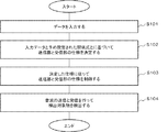
図2は本実施形態に係る目標検出装置10の動作を示すフローチャートである。以下、図2を参照して目標検出装置10の動作を説明する。
FIG. 2 is a flowchart showing the operation of the
目標検出装置10の制御部14は、制御に必要なデータを外部から入力する(ステップS101)。次に制御部14は、入力されたデータと予め設定された関係式とに基づいて、送信部11と受信部12の仕様を決定する(ステップS102)。次に制御部14は、決定した仕様に一致するように送信部11と受信部12の仕様を制御する(ステップS103)。
The
その後、音波の送受信による検出対象物の検出を行う(ステップS104)。具体的には、制御された仕様に従って送信部11が音波を送信すると共に受信部12が音波の反射波を受信し、検出部13が受信部12の出力に基づいて検出対象物15を検出する。
Thereafter, the detection target is detected by transmitting and receiving sound waves (step S104). Specifically, the
このように本実施形態によれば、波動である音波が伝搬する媒質である水による散乱によって受信部12に到達する散乱波の影響を軽減するように送信部11と受信部12の仕様を制御することができる。その理由は、制御部14が、媒質による散乱によって受信部12に到達する散乱波の影響を軽減するための関係式を満足するように、送信部11と受信部12の仕様を制御するためである。
As described above, according to the present embodiment, the specifications of the
[第2の実施形態]
次に本発明の第2の実施形態について説明する。本実施形態では、第1の実施形態に係る目標検出装置10の制御部14の詳細を説明する。[Second Embodiment]
Next, a second embodiment of the present invention will be described. In the present embodiment, details of the
制御部14は、波動が伝搬する媒質による散乱によって受信部に到達する散乱波の影響を軽減するための関係式を満足するように送信部と受信部の仕様を制御する機能を有している。この制御部14は、主な機能部として、通信インターフェース部(以下、通信I/F部という)141、操作入力部142、画面表示部143、記憶部144、および演算処理部145を有する。
The
通信I/F部141は、専用のデータ通信回路からなり、通信回線を介して接続された送信部11や受信部12などの各種装置との間でデータ通信を行う機能を有している。
The communication I /
操作入力部142は、キーボードやマウスなどの操作入力装置からなり、オペレータの操作を検出して演算処理部145に出力する機能を有している。
The
画面表示部143は、LCD(Liquid Crystal Display)やPDP(Plasma Display Panel)などの画面表示装置からなり、演算処理部145からの指示に応じて、操作メニューなどの各種情報を画面表示する機能を有している。
The
記憶部144は、ハードディスクやメモリなどの記憶装置からなり、演算処理部145での各種処理に必要な処理情報やプログラム1441を記憶する機能を有している。プログラム1441は、演算処理部145に読み込まれて実行されることにより各種処理部を実現するプログラムであり、通信I/F部141などのデータ入出力機能を介して外部装置(図示せず)や記憶媒体(図示せず)から予め読み込まれて記憶部144に保存される。記憶部144で記憶される主な処理情報として、関係式1442、入力データ1443、および算出データ1444がある。
The storage unit 144 includes a storage device such as a hard disk or a memory, and has a function of storing processing information and a
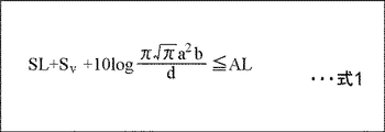
関係式1442は、波動が伝搬する媒質による散乱によって受信部に到達する散乱波の影響を軽減するために送信部と受信部の仕様が満たさなければならない条件を幾つかのパラメータによって表す式である。図4に示す式1は、関係式1442の一例である。
The
式1には、SL,Sv,a,b,d,ALという6個のパラメータがある。SLは送信部11の送信レベル、Sv(=10logsv)は後方散乱強度、a,bは送信部11と受信部12のビーム形状、dは送信部11と受信部12との間の距離、ALは散乱レベルの許容レベル、をそれぞれ表すパラメータである。即ち、式1は、受信部12に到達する散乱波のレベルが許容レベルAL以下となるためには、SL+Sv+10log(π3/2a2b/d)の値がAL以下でなければならないことを表している。従って、幾つかのパラメータの値を既知とすると、その既知の値と式1とから、残りの未知のパラメータの値を決定することができる。例えばSL,Sv,a,b,ALを与えると、最適なdの値が求まる。
図5乃至図7は、式1を導出するために想定した送信部11と受信部12の仕様を表す模式図である。以下、図5乃至図7を参照して、式1の導出過程について説明する。
5 to 7 are schematic diagrams showing the specifications of the
[式1の導出過程]
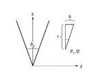
図5に示すように、x-y平面に送信部11と受信部12とが配置されており、送信ビームと受信ビームの形状は同じで、共にz軸の正方向にビームが向いているものとする。また、ビームはガウシアンでz軸を中心とする。ビームのx-y平面に並行な各断面は2次元ガウシアンであり、図8の式2のように記述される。また、z軸の正の向きでガウシアンが広がっていくようにするため、式2を図8の式3のように修正する。[Derivation process of Formula 1]
As shown in FIG. 5, it is assumed that the transmitting
図6に示すように、X方向のビーム幅をθxとし、tan(θx/2)=aとする。また図7に示すように、Y方向のビーム幅をθyとし、tan(θy/2)=bとする。さらに、z軸と同軸に受信ビームがあり、それからx軸の正の方向にdだけ離れたところに同じ形の送信ビームがあるとする。すなわち送信部11と受信部12との間の距離をdとする。このとき送信ビームは図8の式4のように記述される。つまり原点(0,0,0)に受信点があり、(d,0,0)に送信点があるという前提である。As shown in FIG. 6, the beam width in the X direction is θ x, and tan (θ x / 2) = a. Further, as shown in FIG. 7, the beam width in the Y direction is θ y, and tan (θ y / 2) = b. Assume further that there is a receive beam coaxial with the z-axis, and then there is a transmit beam of the same shape at a distance d in the positive direction of the x-axis. That is, the distance between the
単位距離における軸上の音の強さをI0とする。座標(x,y,z)の送信点からの距離は{(x-d)2+y2+z2}1/2であるから、座標(x,y,z)における微小体積dxdydzに入射する音の強さはI0B2(x,y,z)/{(x-d)2+y2+z2}となる。Sv=10log svを後方散乱強度とすると、微小体積dxdydzによる散乱強度は受信点では図8の式5のようになる。これをビームB1(x,y,z)で受けるので、受信部12の出力電圧は図8の式6のようになる。ここで、レスポンスを1としている。よって、全領域の散乱(残響)Rは、図8の式7に示すように、式6を積分することで得られる。Let I 0 be the intensity of the sound on the axis at a unit distance. Since the distance from the transmission point of coordinates (x, y, z) is {(xd) 2 + y 2 + z 2 } 1/2 , the sound incident on the minute volume dxdydz at coordinates (x, y, z) Is I 0 B 2 (x, y, z) / {(xd) 2 + y 2 + z 2 }. Assuming that S v = 10 log s v is the backscattering intensity, the scattering intensity due to the minute volume dxdydz is as shown in Equation 5 in FIG. Since this is received by the beam B 1 (x, y, z), the output voltage of the receiving
さて式7の積分は、解析的には解けない。そこで次のような近似をする。各微小体積の散乱はx-y平面からの距離のみに依存、すなわちzにのみ依存するとする。これはビーム幅が十分狭ければなりたつ。x-y平面からの距離が大きくなるとビームの広がりが大きくなるが、散乱は距離に従って小さくなるため、ビームの広がりの影響も無いであろう。この方針で近似すると前述の積分は、図8の式8に示すようになる。
Now, the integral of
式8の積分は以下のようにして行われる。まずx,yについて積分する。各々独立に積分できる。xについての積分は、図9の式9のようになる。またyについての積分は、図9の式10のようになる。従って、式8は図9の式11のようになる。Zについての積分は(1/z)=tと変数変換すると、(-1/z2)dz=dtであり、図9の式12に示すようになる。よって、積分結果は図9の式13に示すものとなる。対数で表現すると、散乱レベルRL’は図9の式14に示すようになる。この散乱レベルRL’を許容レベルAL以下とする条件が、上述した式1である。以上が、式1の導出過程である。The integration of
再び図3を参照すると、入力データ1443は、関係式1442中の複数のパラメータのうちの既知のパラメータの値である。
Referring back to FIG. 3, the
算出データ1444は、関係式1442と入力データ1443とに基づいて算出された、関係式1442中の未知パラメータの値である。
The calculated
演算処理部145は、MPUなどのマイクロプロセッサとその周辺回路を有し、記憶部144からプログラム1441を読み込んで実行することにより、上記ハードウェアとプログラム1441とを協働させて各種処理部を実現する機能を有している。演算処理部145で実現される主な処理部として、入力部1451と演算部1452と設定部1453とがある。
The
入力部1451は、操作入力部142または通信I/F部141からデータを入力し、記憶部144に入力データ1443として保存する機能を有する。
The
図10乃至図13は入力部1451が画面表示部143に表示するデータ入力画面の例を示す。入力部1451は、まず図10に示すようなデータ入力画面14511を画面表示部143に表示する。データ入力画面14511には、最適化するパラメータの選択ボタン145111〜145113が表示されている。オペレータは、何れかの選択ボタンを操作することによって、最適化するパラメータを選択する。
10 to 13 show examples of data input screens displayed on the
入力部1451は、選択ボタン145111が操作されると、送受信部間の距離を最適化の対象とし、図11に示すようなデータ入力画面14512を画面表示部143に表示する。データ入力画面14512には、送信レベルSLの入力欄145121、後方散乱強度Svの入力欄145122、X軸ビーム幅aの入力欄145123、Y軸ビーム幅bの入力欄145124、許容レベルALの入力欄145125、実行ボタン145126が表示されている。オペレータは、操作入力部142から入力欄145121〜145125に所望の数値を入力し、実行ボタン145126を操作する。すると、入力部1451は、入力欄145121〜145125に入力された各パラメータの値を入力データ1443として記憶部144に保存する。When the
また入力部1451は、選択ボタン145112が操作されると、X軸ビーム幅を最適化の対象とし、図12に示すようなデータ入力画面14513を画面表示部143に表示する。データ入力画面14513には、送信レベルSLの入力欄145131、後方散乱強度Svの入力欄145132、Y軸ビーム幅bの入力欄145133、送受信部間の距離dの入力欄145134、許容レベルALの入力欄145135、実行ボタン145136が表示されている。オペレータは、操作入力部142から入力欄145131〜145135に所望の数値を入力し、実行ボタン145136を操作する。すると、入力部1451は、入力欄145131〜145135に入力された各パラメータの値を入力データ1443として記憶部144に保存する。In addition, when the
また入力部1451は、選択ボタン145113が操作されると、Y軸ビーム幅を最適化の対象とし、図13に示すようなデータ入力画面14514を画面表示部143に表示する。データ入力画面14514には、送信レベルSLの入力欄145141、後方散乱強度Svの入力欄145142、X軸ビーム幅aの入力欄145143、送受信部間の距離dの入力欄145144、許容レベルALの入力欄145145、実行ボタン145146が表示されている。オペレータは、操作入力部142から入力欄145141〜145145に所望の数値を入力し、実行ボタン145146を操作する。すると、入力部1451は、入力欄145141〜145145に入力された各パラメータの値を入力データ1443として記憶部144に保存する。When the
上記の例では、入力部1451は、画面表示部143にデータ入力画面を表示し、操作入力部142からデータを入力したが、通信I/F部141を通じて接続された遠隔地の端末装置にデータ入力画面を表示し、その端末装置からデータを入力するようにしてもよい。
In the above example, the
演算部1452は、記憶部144から関係式1442と入力データ1443とを読み込み、この関係式1442と入力データ1443とに基づいて、最適化対象のパラメータの値を算出し、記憶部144に算出データ1444として保存する機能を有する。具体的には、演算部1452は、関係式1442中の複数のパラメータのうちの既知のパラメータに入力データ1443を代入し、関係式1442を未知パラメータについて解法することにより、最適化対象のパラメータの値を算出する。
The
設定部1453は、記憶部144から入力データ1443と算出データ1444とを読み込み、この入力データ1443と算出データ1444とに基づいて、送信部11と受信部12の仕様を制御する機能を有する。
The
図14は送信部11と受信部12の仕様を制御する構成の一例を示す。図14を参照すると、送信部11は移動体14531に搭載され、受信部12は移動体14532に搭載されている。移動体14531、14532は、設定部1453からの指示に従って、船底等に設けられたレールなどの案内部材14533に沿ってX軸と並行に移動する。設定部1453は、移動体14531と移動体14532の位置を調整することにより、送信部11と受信部12との間の距離を制御する。
FIG. 14 shows an example of a configuration for controlling the specifications of the
図15は送信部11と受信部12の仕様を制御する構成の他の例を示す。図15を参照すると、送信部11の送信ビーム形状を形成する送信ビーム形成部14534と、受信部12の受信ビーム形状を形成する受信ビーム形成部14535とが設けられている。設定部1453は、送信ビーム形成部14534と受信ビーム形成部14535とに対して指示を出すことにより、送信ビーム形状および受信ビーム形状が所望の形状となるように制御する。
FIG. 15 shows another example of a configuration for controlling the specifications of the
図16は本実施形態に係る制御部14の動作を示すフローチャートである。以下、図16を参照して制御部14の動作を説明する。
FIG. 16 is a flowchart showing the operation of the
制御部14の入力部1451は、まず図10に示すようなデータ入力画面14511を画面表示部143に表示し、選択ボタン145111〜145113によってオペレータに最適化するパラメータを選択させる(ステップS201)。次に入力部1451は、選択された最適化パラメータの種類に応じた図11〜図13に示すようなデータ入力画面14512〜14514を画面表示部143に表示し、既知パラメータの値をオペレータに入力させる(ステップS202)。
First, the
次に制御部14の演算部1452は、入力された既知パラメータの値と式1の関係式とに基づいて、最適化対象の未知パラメータの値を算出する(ステップS203)。例えば演算部1452は、送受信部間の距離が最適化対象に選択され、データ入力画面14512を通じて送信レベルSL、後方散乱強度Sv、X軸ビーム幅a、Y軸ビーム幅b、許容レベルALの値がオペレータから入力されると、それらの値を式1に代入し、関係式1を満足する送受信部間の距離dの最小値を最適値として算出する。また演算部1452は、X軸ビーム幅が最適化対象に選択され、データ入力画面14513を通じて送信レベルSL、後方散乱強度Sv、Y軸ビーム幅b、送受信部間の距離d、許容レベルALの値がオペレータから入力されると、それらの値を式1に代入し、関係式1を満足するX軸ビーム幅aの最小値を最適値として算出する。また演算部1452は、Y軸ビーム幅が最適化対象に選択され、データ入力画面14514を通じて送信レベルSL、後方散乱強度Sv、X軸ビーム幅a、送受信部間の距離d、許容レベルALの値がオペレータから入力されると、それらの値を式1に代入し、関係式1を満足するY軸ビーム幅bの最小値を最適値として算出する。Next, the
次に制御部14の設定部1453は、オペレータから入力された既知パラメータの値と算出された未知パラメータの値とに基づいて、送信部11と受信部12の仕様を制御する(ステップS204)。具体的には、設定部1453は、図14に示す移動体14531、14532の少なくとも一方を移動させて送信部11と受信部12との間の距離がパラメータdの値に合致するように調整する。また設定部1453は、図15に示す送信ビーム形成部14534と受信ビーム形成部14535とに指示を出して送信部11の送信ビーム形状と受信部12の送信ビーム形状とがパラメータa、bに合致するように調整する。また設定部1453は、送信部11の送信レベルがパラメータSLに合致するように制御する。なお、ビームの向き等、その他の送受信部の仕様は予め固定されていてもよいし、設定部1453がその都度、所定の状態に設定してもよい。
Next, the
設定部1453による送受信部の仕様の設定後、音波の送受信による検出対象物の検出が行われる。
After setting of the specification of the transmission / reception unit by the
このように本実施形態によれば、波動である音波が伝搬する媒質である水による散乱によって受信部12に到達する散乱波の影響を軽減するように送信部11と受信部12の仕様を制御することができる。その理由は、制御部14が、式1、すなわち、送信部11の送信レベルを表すパラメータSL、媒質の後方散乱強度を表すパラメータSv、送信部11および受信部12のビーム形状を表すパラメータa,b、送受信部間の距離を表すパラメータd、送信レベルの許容レベルを表すパラメータALを有し、媒質による散乱によって受信部12に到達する散乱波の影響を軽減するための式1を満足するように、送信部11と受信部12の仕様を制御するためである。As described above, according to the present embodiment, the specifications of the
[第3の実施形態]
次に本発明の第3の実施形態について説明する。[Third embodiment]
Next, a third embodiment of the present invention will be described.
第2の実施形態では、図4に示す式1を関係式1442として使用したが、本実施形態では、図17に示す式15を関係式1442として使用する。以下、式15の導出過程について説明する。
In the second embodiment,
[式15の導出過程]
目標の検出のし易さを示す指標として、目標からの反射のレベルと残響のレベルの比を考える。ここで、式1の導出過程における式13で与えられるR’が残響のレベルを表す。従って、目標からの反射のレベルをEとすると、上記指標はE/R’となる。また、目標からの反射のレベルEは、I0(単位距離における軸上の音の強さ)に比例する。このため、E/R’は、図17の式16に示すようにI0に依存しない。即ち、SLに依存しない。そして、残響の影響を軽減するための条件として、E/R’が所定の閾値α以上であることを考えると、図17の式15が成立する。[Derivation Process of Equation 15]
As an index indicating the ease of detection of a target, the ratio between the level of reflection from the target and the level of reverberation is considered. Here, R ′ given by
本実施形態では、関係式1442として使用する式15は、媒質の後方散乱強度を表すパラメータSv、送信部11および受信部12のビーム形状を表すパラメータa,b、送受信部間の距離を表すパラメータd、送信レベルの許容レベルを表すパラメータAL、閾値αを有する。そのため、入力部1451が使用するデータ入力画面14512〜14514における送信レベルSLの入力欄145121、145131、145141の代わりに、閾値αの入力欄を使用すればよい。In this embodiment, Expression 15 used as the
[第4の実施形態]
次に本発明の第4の実施形態について説明する。[Fourth Embodiment]
Next, a fourth embodiment of the present invention will be described.
本実施形態では、送信が水平方向に無指向の構成について説明する。第2の実施形態では、図4に示す式1を関係式1442として使用したが、本実施形態では、図18に示す式17を関係式1442として使用する。
In the present embodiment, a configuration in which transmission is omnidirectional in the horizontal direction will be described. In the second embodiment,
式17には、SL,Sv,d,f,g,h,ALという7個のパラメータがある。SLは送信部11の送信レベル、Sv=10logsvは後方散乱強度、dは送信部11と受信部12との間の距離、f,g,hは送信部11と受信部12のビーム形状、ALは散乱レベルの許容レベル、をそれぞれ表すパラメータである。即ち、式17は、受信部12に到達する散乱波のレベルが許容レベルAL以下となるためには、SL+Sv+10log(π3/2fgh/d)の値がAL以下でなければならないことを表している。従って、幾つかのパラメータの値を既知とすると、その既知の値と式17とから、残りの未知のパラメータの値を決定することができる。例えばSL,Sv,f,g,h,ALを与えると、最適なdの値が求まる。
図19は、式17を導出するために想定した送信部11と受信部12の仕様を表す模式図である。以下、図19を参照して、式17の導出過程について説明する。
FIG. 19 is a schematic diagram illustrating the specifications of the
[式17の導出過程]
図19に示すように、XYZ座標の原点からZ軸方向の距離dの位置に送信部11が配置され、受信部12は原点に配置されているものとする。送信ビーム401は水平方向に無指向であり、ビーム幅はfである。また受信ビーム402は図19に示すような形状を有し、水平方向のビーム幅はh、垂直方向のビーム幅はgである。以下では、円筒座標で考える。[Derivation Process of Equation 17]
As illustrated in FIG. 19, it is assumed that the
送信は水平方向にオムニであり、図20の式18に示すように表す。また受信は図20の式19に示すように表す。
Transmission is omnidirectional in the horizontal direction and is expressed as shown in Equation 18 in FIG. The reception is expressed as shown in
単位距離における軸上の音の強さをI0とする。座標(r,θ,z)の送信点からの距離は{r2+(z-d)2}1/2であるから、座標(r,θ,z)における微小体積rdrdθdzに入射する音の強さは{I0B3(r,θ,z)/{r2+(z-d)2}となる。Sv=10log svを後方散乱強度とすると、微小体積rdrdθdzによる散乱強度は受信点では図20の式20のようになる。これをビームB4(r,θ,z)で受けるので、受信部12の出力電圧は図20の式21のようになる。ここで、レスポンスを1としている。よって、全領域の残響Rは、図20の式22に示すように、式21を積分することで得られる。Let I 0 be the intensity of the sound on the axis at a unit distance. Since the distance from the transmission point of the coordinates (r, θ, z) is {r 2 + (zd) 2 } 1/2 , the intensity of the sound incident on the minute volume rdrdθdz at the coordinates (r, θ, z) Becomes {I 0 B 3 (r, θ, z) / {r 2 + (zd) 2 }. Assuming that S v = 10 log s v is the backscattering intensity, the scattering intensity due to the minute volume rdrdθdz is as shown in
上記積分は解析的に実行できないため、近似を行う。今回は残響はz軸からのみに依存するという考え、つまりrにのみ依存するとする。すると上記積分は、図21の式23のようになる。 Since the above integration cannot be performed analytically, approximation is performed. This time, reverberation depends only on the z axis, that is, only on r. Then, the integration is as shown in Equation 23 in FIG.
式23の積分は以下のようにして行われる。まずzについて積分する。これは普通のガウシアンの積分であり、図21の式24のようになる。次にθについて積分する。ビーム中心が積分範囲の中心になるように座標を設定し、積分範囲の中心から離れた場所、すなわちθ=0,2πではビームがゼロであるとみなすと、0≦θ<2πの積分を-∞<θ<∞の積分と読み替えることができる。するとθについての積分は図21の式25のようになる。 The integration of Equation 23 is performed as follows. First, integrate over z. This is an ordinary Gaussian integral, as shown in Equation 24 in FIG. Next, integration is performed with respect to θ. If the coordinates are set so that the center of the beam is the center of the integration range, and it is considered that the beam is zero at a location away from the center of the integration range, that is, θ = 0, 2π, the integration of 0 ≤ θ <2π is- It can be read as integration with ∞ <θ <∞. Then, the integration with respect to θ is as shown in Equation 25 in FIG.
従って、R’の積分は図21の式26のようになる。また式26におけるR”は、図22の式27のようになる。Rについての積分は(1/r)=tと変数変換すると、(-1/r2)dr=dtであり、図22の式28に示すようになる。よって、R”は図22の式29に示すようになる。対数で表現すると、残響レベルRL”は図22の式30に示すようになる。この残響レベルRL”を許容レベルAL以下とする条件が、上述した式17である。以上が、式17の導出過程である。Therefore, the integration of R ′ is as shown in Equation 26 in FIG. Further, R ″ in Expression 26 is as shown in
式17によれば、例えばSL,SV,f,g,h,AL,αが与えられれば、送信部11と受信部12との間の最適距離が求まる。また、例えばSL,SV,d,g,h,AL,αが与えられれば、送信部11の最適なz軸ビーム幅(最適ビーム形状の一種)が求まる。式17中の既知パラメータの値は第2の実施形態と同様に、グラフィカルユーザインターフェイスを通じてオペレータから入力してよい。According to
[第5の実施形態]
次に本発明の第5の実施形態について説明する。[Fifth Embodiment]
Next, a fifth embodiment of the present invention will be described.
第4の実施形態では、図18に示す式17を関係式1442として使用したが、本実施形態では、図23に示す式31を関係式1442として使用する。以下、式31の導出過程について説明する。
In the fourth embodiment,
[式31の導出過程]
目標の検出のし易さを示す指標として、目標からの反射のレベルと残響のレベルの比を考える。ここで、式17の導出過程における式29で与えられるR”が残響のレベルを表す。従って、目標からの反射のレベルをEとすると、上記指標はE/R”となる。また、目標からの反射のレベルEは、I0(単位距離における軸上の音の強さ)に比例する。このため、E/R”は、図23の式32に示すようにI0に依存しない。即ち、SLに依存しない。そして、残響の影響を軽減するための条件として、E/R”が所定の閾値α以上であることを考えると、図23の式31が成立する。[Derivation Process of Equation 31]
As an index indicating the ease of detection of a target, the ratio between the level of reflection from the target and the level of reverberation is considered. Here, R ″ given by Equation 29 in the derivation process of
[その他の実施形態]
以上、本発明を幾つかの実施形態を挙げて説明したが、本発明は以上の実施形態に限定されず、その他各種の付加変更が可能である。例えば以下のような実施形態も本発明に含まれる。[Other embodiments]
Although the present invention has been described with reference to some embodiments, the present invention is not limited to the above embodiments, and various other additions and modifications can be made. For example, the following embodiments are also included in the present invention.
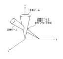
例えば図24に示すように、送信部11のビーム(送信ビーム)と受信部12のビーム(受信ビーム)の向きを変え、双方のビームが重なった部分の散乱強度を積分した値が最小になるように、お互いのビームの向きを決定すると、その決定したビームの向きが最適なビームの向きになる。そのため、波動が伝搬する媒質による散乱によって受信部に到達する散乱波の影響を軽減するための関係式をビームの向きを考慮して立式し、その関係式を満足するように送信部と受信部のビームの向きを制御するようにしてもよい。但し、送信ビームと受信ビームが重なる領域に目標が存在する必要があるため、目標の位置を考慮する必要がある。 For example, as shown in FIG. 24, the direction of the beam of the transmission unit 11 (transmission beam) and the direction of the beam of the reception unit 12 (reception beam) is changed, and the value obtained by integrating the scattered intensities of the overlapping portions of both beams is minimized. Thus, when the direction of each beam is determined, the determined beam direction becomes the optimum beam direction. For this reason, a relational expression for reducing the influence of scattered waves reaching the receiver due to scattering by the medium through which the wave propagates is formed in consideration of the direction of the beam, and the transmitter and the receiver are satisfied so that the relational expression is satisfied. You may make it control the direction of the beam of a part. However, since the target needs to exist in a region where the transmission beam and the reception beam overlap, it is necessary to consider the position of the target.
また上記の実施形態では、関係式1442中の複数のパラメータのうち、値を既知とするパラメータの値をオペレータから入力するようにしたが、値を既知とするパラメータの値の全部または一部(例えば後方散乱強度など)を固定値として記憶部144に記憶するようにしてもよい。
In the above embodiment, among the plurality of parameters in the
また上記の実施形態では、本発明をアクティブソーナーに適用した実施形態について説明したが、本発明はアクティブソーナーに限定されず、レーダー装置、ライダー装置など、音波、電波、光波などの波動を送信し、目標からの反射波を受信して目標を検出する装置全般に適用できる。
以上、実施形態(及び実施例)を参照して本願発明を説明したが、本願発明は上記実施形態(及び実施例)に限定されものではない。本願発明の構成や詳細には、本願発明のスコープ内で当業者が理解し得る様々な変更をすることができる。
この出願は、2014年6月9日に出願された日本出願特願2014−118541を基礎とする優先権を主張し、その開示の全てをここに取り込む。In the above embodiment, the embodiment in which the present invention is applied to an active sonar has been described. However, the present invention is not limited to an active sonar, and a wave such as a sound wave, radio wave, or light wave is transmitted from a radar device, a rider device, or the like. The present invention can be applied to all devices that detect a target by receiving a reflected wave from the target.
While the present invention has been described with reference to the embodiments (and examples), the present invention is not limited to the above embodiments (and examples). Various changes that can be understood by those skilled in the art can be made to the configuration and details of the present invention within the scope of the present invention.
This application claims the priority on the basis of Japanese application Japanese Patent Application No. 2014-118541 for which it applied on June 9, 2014, and takes in those the indications of all here.
10…目標検出装置
11…送信部
12…受信部
13…検出部
14…制御部
15…検出対象物DESCRIPTION OF
Claims (8)
検出対象物から反射された前記波動の反射波を受信する受信部と、
前記受信部の出力に基づいて前記検出対象物を検出する検出部と、
前記送信部および前記受信部のビーム形状および前記受信部と前記送信部との間の距離の何れか一方を最適化の対象として選択し、前記送信部の送信レベル及び前記波動が伝搬する媒質の後方散乱強度を入力データから取得し、前記送信レベル、前記後方散乱強度、前記ビーム形状、および前記距離に基づいて前記受信部に到達する前記媒質による散乱波のレベルを算出し、算出された前記散乱波のレベルが前記送信レベルの許容レベル以下となる、前記ビーム形状および前記距離の何れか一方の値を算出する制御部とを有する目標検出装置。 A transmission unit for transmitting waves;
A receiving unit that receives a reflected wave of the wave reflected from the detection object;
A detection unit for detecting the detection object based on an output of the reception unit;
The beam shape of the transmission unit and the reception unit and the distance between the reception unit and the transmission unit are selected as optimization targets, and the transmission level of the transmission unit and the medium in which the wave propagates are selected. Obtaining the backscattering intensity from the input data, calculating the level of the scattered wave by the medium reaching the receiving unit based on the transmission level, the backscattering intensity, the beam shape, and the distance, the calculated A target detection apparatus comprising: a control unit that calculates one of the beam shape and the distance, wherein a scattered wave level is equal to or lower than an allowable level of the transmission level .
検出対象物から反射された前記波動の反射波を受信する受信部と、
前記受信部の出力に基づいて前記検出対象物を検出する検出部と、
前記送信部および前記受信部のビーム形状および前記受信部と前記送信部との間の距離の何れか一方を最適化の対象として選択し、前記送信部の送信レベル及び前記波動が伝播する媒質の後方散乱強度を入力データから取得し、前記送信レベル、前記後方散乱強度、前記ビーム形状、および前記距離に基づいて前記受信部に到達する前記媒質による散乱波のレベルに対する前記検出対象物からの反射波のレベルの比を算出し、算出された前記比が前記送信レベルの許容レベル以下となる、前記ビーム形状および前記距離の何れか一方の値を算出する制御部とを有する目標検出装置。 A transmission unit for transmitting waves;
A receiving unit that receives a reflected wave of the wave reflected from the detection object;
A detection unit for detecting the detection object based on an output of the reception unit;
The beam shape of the transmission unit and the reception unit and the distance between the reception unit and the transmission unit are selected as optimization targets, and the transmission level of the transmission unit and the medium in which the wave propagates are selected. A backscattering intensity is obtained from input data, and a reflection from the detection object with respect to a level of a scattered wave by the medium reaching the receiving unit based on the transmission level, the backscattering intensity, the beam shape, and the distance. A target detection apparatus comprising: a controller that calculates a ratio of wave levels and calculates one of the beam shape and the distance, wherein the calculated ratio is equal to or less than an allowable level of the transmission level .
前記制御部は、前記受信部と前記送信部との間の距離が算出された前記距離に合致するように前記移動体を移動させる請求項1または2に記載の目標検出装置。 A moving body that moves at least one of the transmission unit and the reception unit;
The target detection apparatus according to claim 1 , wherein the control unit moves the moving body so that a distance between the reception unit and the transmission unit matches the calculated distance .
前記受信部の受信ビーム形状を形成する受信ビーム形成部とを有し、
前記制御部は、前記送信ビーム形状と前記受信ビーム形状とが算出された前記送信部及び前記受信部のビーム形状に合致するように前記送信ビーム形成部および前記受信ビーム形成部を制御する請求項1乃至3の何れかに記載の目標検出装置。 A transmission beam forming unit for forming a transmission beam shape of the transmission unit;
A receiving beam forming unit for forming a receiving beam shape of the receiving unit,
The said control part controls the said transmission beam formation part and the said reception beam formation part so that the transmission beam shape and the said reception beam shape may correspond to the beam shape of the said transmission part and the said reception part which were calculated. The target detection apparatus according to any one of 1 to 3 .
受信部が検出対象物から反射された前記波動の反射波を受信し、The receiving unit receives the reflected wave of the wave reflected from the detection object,
前記受信部の出力に基づいて前記検出対象物を検出し、Detecting the detection object based on the output of the receiving unit;
前記送信部および前記受信部のビーム形状および前記受信部と前記送信部との間の距離の何れか一方を最適化の対象として選択し、Select one of the beam shape of the transmitter and the receiver and the distance between the receiver and the transmitter as an optimization target,
前記送信部の送信レベル及び前記波動が伝搬する媒質の後方散乱強度を入力データから取得し、Obtaining the transmission level of the transmitter and the backscattering intensity of the medium in which the wave propagates from input data;
前記送信レベル、前記後方散乱強度、前記ビーム形状、および前記距離に基づいて前記受信部に到達する前記媒質による散乱波のレベルを算出し、Based on the transmission level, the backscattering intensity, the beam shape, and the distance, the level of the scattered wave by the medium reaching the receiving unit is calculated,
算出された前記散乱波のレベルが前記送信レベルの許容レベル以下となる、前記ビーム形状および前記距離の何れか一方の値を算出する目標検出方法。A target detection method for calculating one of the beam shape and the distance, wherein the calculated scattered wave level is equal to or lower than an allowable level of the transmission level.
受信部が検出対象物から反射された前記波動の反射波を受信し、The receiving unit receives the reflected wave of the wave reflected from the detection object,
前記受信部の出力に基づいて前記検出対象物を検出し、Detecting the detection object based on the output of the receiving unit;
前記送信部および前記受信部のビーム形状および前記受信部と前記送信部との間の距離の何れか一方を最適化の対象として選択し、Select one of the beam shape of the transmitter and the receiver and the distance between the receiver and the transmitter as an optimization target,
前記送信部の送信レベル及び前記波動が伝播する媒質の後方散乱強度を入力データから取得し、Obtaining the transmission level of the transmitter and the backscattering intensity of the medium through which the wave propagates from input data,
前記送信レベル、前記後方散乱強度、前記ビーム形状、および前記距離に基づいて前記受信部に到達する前記媒質による散乱波のレベルに対する前記検出対象物からの反射波のレベルの比を算出し、Based on the transmission level, the backscattering intensity, the beam shape, and the distance, the ratio of the level of the reflected wave from the detection object to the level of the scattered wave by the medium reaching the receiving unit is calculated,
算出された前記比が前記送信レベルの許容レベル以下となる、前記ビーム形状および前記距離の何れか一方の値を算出する目標検出方法。A target detection method for calculating any one of the beam shape and the distance, wherein the calculated ratio is equal to or less than an allowable level of the transmission level.
前記送信部および前記受信部のビーム形状および前記受信部と前記送信部との間の距離の何れか一方を最適化の対象として選択し、前記送信部の送信レベル及び前記波動が伝搬する媒質の後方散乱強度を入力データから取得し、前記送信レベル、前記後方散乱強度、前記ビーム形状、および前記距離に基づいて前記受信部に到達する前記媒質による散乱波のレベルを算出し、算出された前記散乱波のレベルが前記送信レベルの許容レベル以下となる、前記ビーム形状および前記距離の何れか一方の値を算出する制御部として機能させるためのプログラム。 A computer connected to a transmission unit that transmits a wave and a reception unit that receives a reflected wave of the wave reflected from the detection target;
The beam shape of the transmission unit and the reception unit and the distance between the reception unit and the transmission unit are selected as optimization targets, and the transmission level of the transmission unit and the medium in which the wave propagates are selected. Obtaining the backscattering intensity from the input data, calculating the level of the scattered wave by the medium reaching the receiving unit based on the transmission level, the backscattering intensity, the beam shape, and the distance, the calculated The program for functioning as a control part which calculates the value of any one of the said beam shape and the said distance from which the level of a scattered wave becomes below the allowable level of the said transmission level .
前記送信部および前記受信部のビーム形状および前記受信部と前記送信部との間の距離の何れか一方を最適化の対象として選択し、前記送信部の送信レベル及び前記波動が伝播する媒質の後方散乱強度を入力データから取得し、前記送信レベル、前記後方散乱強度、前記ビーム形状、および前記距離に基づいて前記受信部に到達する前記媒質による散乱波のレベルに対する前記検出対象物からの反射波のレベルの比を算出し、算出された前記比が前記送信レベルの許容レベル以下となる、前記ビーム形状および前記距離の何れか一方の値を算出する制御部として機能させるためのプログラム。 A computer connected to a transmission unit that transmits a wave and a reception unit that receives a reflected wave of the wave reflected from the detection target;
The beam shape of the transmission unit and the reception unit and the distance between the reception unit and the transmission unit are selected as optimization targets, and the transmission level of the transmission unit and the medium in which the wave propagates are selected. A backscattering intensity is obtained from input data, and a reflection from the detection object with respect to a level of a scattered wave by the medium reaching the receiving unit based on the transmission level, the backscattering intensity, the beam shape, and the distance. A program for calculating a ratio of wave levels, and for causing the calculated ratio to be equal to or less than an allowable level of the transmission level and functioning as a controller that calculates one of the beam shape and the distance .
Applications Claiming Priority (3)
| Application Number | Priority Date | Filing Date | Title |
|---|---|---|---|
| JP2014118541 | 2014-06-09 | ||
| JP2014118541 | 2014-06-09 | ||
| PCT/JP2015/002745 WO2015190058A1 (en) | 2014-06-09 | 2015-06-01 | Target detection device |
Publications (2)
| Publication Number | Publication Date |
|---|---|
| JPWO2015190058A1 JPWO2015190058A1 (en) | 2017-04-20 |
| JP6323552B2 true JP6323552B2 (en) | 2018-05-16 |
Family
ID=54833176
Family Applications (1)
| Application Number | Title | Priority Date | Filing Date |
|---|---|---|---|
| JP2016527624A Active JP6323552B2 (en) | 2014-06-09 | 2015-06-01 | Target detection device |
Country Status (5)
| Country | Link |
|---|---|
| US (1) | US10495742B2 (en) |
| EP (1) | EP3153880B1 (en) |
| JP (1) | JP6323552B2 (en) |
| CA (1) | CA2950875C (en) |
| WO (1) | WO2015190058A1 (en) |
Families Citing this family (3)
| Publication number | Priority date | Publication date | Assignee | Title |
|---|---|---|---|---|
| JP6610977B2 (en) * | 2016-03-24 | 2019-11-27 | 日本電気株式会社 | Target detection system, method and program |
| US10531187B2 (en) * | 2016-12-21 | 2020-01-07 | Nortek Security & Control Llc | Systems and methods for audio detection using audio beams |
| JP7468415B2 (en) * | 2021-03-16 | 2024-04-16 | 三菱電機株式会社 | Semiconductor device, power conversion device, and method for manufacturing the semiconductor device |
Family Cites Families (19)
| Publication number | Priority date | Publication date | Assignee | Title |
|---|---|---|---|---|
| US4961174A (en) | 1977-05-09 | 1990-10-02 | The United States Of America As Represented By The Secretary Of The Navy | High data rate continuous wave towed sonar |
| US4187488A (en) * | 1978-03-20 | 1980-02-05 | The United States Of America As Represented By The Secretary Of The Navy | Reverberation backscatter measurement system |
| US4717862A (en) * | 1984-11-19 | 1988-01-05 | The United States Government As Represented By The Secretary Of The Navy | Pulsed illumination projector |
| JP2570385B2 (en) * | 1988-06-03 | 1997-01-08 | 日本電気株式会社 | Simulated underwater reverberation signal generator |
| JPH03115882A (en) * | 1989-09-29 | 1991-05-16 | Nec Corp | Active sonar apparatus |
| JPH0660841B2 (en) * | 1989-10-26 | 1994-08-10 | 防衛庁技術研究本部長 | Reverberation simulation method |
| JPH0452584A (en) * | 1990-06-20 | 1992-02-20 | Nec Corp | Active sonar device |
| JP2601053B2 (en) * | 1991-04-12 | 1997-04-16 | 日本電気株式会社 | Active sonar device for underwater vehicles |
| US5243541A (en) * | 1991-10-11 | 1993-09-07 | Kaman Aerospace Corporation | Imaging lidar system for shallow and coastal water |
| JPH0862323A (en) * | 1994-08-25 | 1996-03-08 | Mitsubishi Heavy Ind Ltd | Receiving device and transmitting device |
| JP2905785B2 (en) * | 1996-04-02 | 1999-06-14 | 防衛庁技術研究本部長 | Scattering coefficient estimation method |
| JP2976016B2 (en) * | 1997-04-03 | 1999-11-10 | 防衛庁技術研究本部長 | High-speed simulation of underwater reverberation |
| JP3367462B2 (en) | 1999-04-20 | 2003-01-14 | 日本電気株式会社 | Active sonar and target detection method thereof |
| JP2000310557A (en) * | 1999-04-27 | 2000-11-07 | Oki Electric Ind Co Ltd | Underwater acoustic evaluating apparatus |
| JP2001174545A (en) | 1999-12-15 | 2001-06-29 | Nec Network Sensa Kk | Underwater stationary object detecting method and device |
| US8363744B2 (en) * | 2001-06-10 | 2013-01-29 | Aloft Media, Llc | Method and system for robust, secure, and high-efficiency voice and packet transmission over ad-hoc, mesh, and MIMO communication networks |
| JP4568413B2 (en) * | 2000-09-08 | 2010-10-27 | 三菱重工業株式会社 | Sound simulator for transducers |
| EP1692542A4 (en) | 2003-09-29 | 2011-03-30 | Ac Capital Man Inc | Sonar system and process |
| EP2845191B1 (en) * | 2012-05-04 | 2019-03-13 | Xmos Inc. | Systems and methods for source signal separation |
-
2015
- 2015-06-01 CA CA2950875A patent/CA2950875C/en active Active
- 2015-06-01 WO PCT/JP2015/002745 patent/WO2015190058A1/en not_active Ceased
- 2015-06-01 US US15/313,677 patent/US10495742B2/en active Active
- 2015-06-01 EP EP15806369.3A patent/EP3153880B1/en active Active
- 2015-06-01 JP JP2016527624A patent/JP6323552B2/en active Active
Also Published As
| Publication number | Publication date |
|---|---|
| WO2015190058A1 (en) | 2015-12-17 |
| US10495742B2 (en) | 2019-12-03 |
| US20170184712A1 (en) | 2017-06-29 |
| CA2950875C (en) | 2019-04-16 |
| JPWO2015190058A1 (en) | 2017-04-20 |
| CA2950875A1 (en) | 2015-12-17 |
| EP3153880A4 (en) | 2018-02-21 |
| EP3153880A1 (en) | 2017-04-12 |
| EP3153880B1 (en) | 2021-12-01 |
Similar Documents
| Publication | Publication Date | Title |
|---|---|---|
| JP6266002B2 (en) | Disturbance mitigation for touch screen systems | |
| AU2015291223B2 (en) | Depth display using sonar data | |
| US11022684B2 (en) | Alert zones for a marine environment | |
| JP6323552B2 (en) | Target detection device | |
| CN106205585B (en) | Noise elimination method and device | |
| US10684367B2 (en) | Ultrasound sensor and object detecting method thereof | |
| CN112383857B (en) | Earphone control method, control device and earphone | |
| US20170150947A1 (en) | Ultrasonic diagnostic device | |
| JP6973129B2 (en) | Target motion analysis system and target motion analysis method | |
| JP2016020841A (en) | Noises and/or vibrations monitoring method and monitoring system | |
| WO2012131355A1 (en) | User interfaces for electronic devices | |
| JP2014081241A (en) | Radar device and radar reception signal processing method | |
| WO2017164365A1 (en) | Target detection system, method, and program | |
| JP5991599B2 (en) | Target detection device | |
| US10761185B2 (en) | Signal processing device, signal processing method, recording medium, target detection device, and target detection method | |
| JP6286896B2 (en) | SONER RECEIVER POSITION POSITION DEVICE AND PREDICTION METHOD | |
| EP2797793B1 (en) | Systems and methods for proximal object awareness | |
| JP6598308B2 (en) | Sonar device, acoustic signal processing system, acoustic signal processing method, and acoustic signal processing program | |
| JP2006329669A (en) | Radar equipment | |
| JP2016121970A (en) | Echo signal processing device, radar device, echo signal processing method, and program | |
| JP2022027091A (en) | Ultrasonic object detection device, method of controlling the same, and control program for the same | |
| US12578447B2 (en) | Radar device and method of controlling radar device | |
| JP6290540B2 (en) | Radar equipment | |
| JP2015193326A (en) | Tracking control device and tracking control method | |
| GB2569620A (en) | Optimization of the performances of an antenna array |
Legal Events
| Date | Code | Title | Description |
|---|---|---|---|
| A621 | Written request for application examination |
Free format text: JAPANESE INTERMEDIATE CODE: A621 Effective date: 20161116 |
|
| A131 | Notification of reasons for refusal |
Free format text: JAPANESE INTERMEDIATE CODE: A131 Effective date: 20170919 |
|
| A521 | Request for written amendment filed |
Free format text: JAPANESE INTERMEDIATE CODE: A523 Effective date: 20171117 |
|
| TRDD | Decision of grant or rejection written | ||
| A01 | Written decision to grant a patent or to grant a registration (utility model) |
Free format text: JAPANESE INTERMEDIATE CODE: A01 Effective date: 20180313 |
|
| A61 | First payment of annual fees (during grant procedure) |
Free format text: JAPANESE INTERMEDIATE CODE: A61 Effective date: 20180326 |
|
| R150 | Certificate of patent or registration of utility model |
Ref document number: 6323552 Country of ref document: JP Free format text: JAPANESE INTERMEDIATE CODE: R150 |