JP6318253B2 - Application-specific network access blocking method and user device - Google Patents
Application-specific network access blocking method and user device Download PDFInfo
- Publication number
- JP6318253B2 JP6318253B2 JP2016538876A JP2016538876A JP6318253B2 JP 6318253 B2 JP6318253 B2 JP 6318253B2 JP 2016538876 A JP2016538876 A JP 2016538876A JP 2016538876 A JP2016538876 A JP 2016538876A JP 6318253 B2 JP6318253 B2 JP 6318253B2
- Authority
- JP
- Japan
- Prior art keywords
- acdc
- application
- information
- category
- layer
- Prior art date
- Legal status (The legal status is an assumption and is not a legal conclusion. Google has not performed a legal analysis and makes no representation as to the accuracy of the status listed.)
- Active
Links
- 238000000034 method Methods 0.000 title claims description 249
- 230000000903 blocking effect Effects 0.000 title description 135
- 238000007689 inspection Methods 0.000 claims description 59
- 238000004891 communication Methods 0.000 claims description 16
- 238000012360 testing method Methods 0.000 claims description 7
- 230000005540 biological transmission Effects 0.000 description 47
- 238000007726 management method Methods 0.000 description 42
- 230000011664 signaling Effects 0.000 description 27
- 238000011084 recovery Methods 0.000 description 20
- 238000010586 diagram Methods 0.000 description 18
- 230000014509 gene expression Effects 0.000 description 15
- 230000004044 response Effects 0.000 description 14
- 230000008569 process Effects 0.000 description 12
- 238000010295 mobile communication Methods 0.000 description 10
- 230000008859 change Effects 0.000 description 8
- 238000013468 resource allocation Methods 0.000 description 8
- 238000005516 engineering process Methods 0.000 description 5
- 230000000977 initiatory effect Effects 0.000 description 5
- 238000012986 modification Methods 0.000 description 5
- 230000004048 modification Effects 0.000 description 5
- 230000004913 activation Effects 0.000 description 3
- 230000009977 dual effect Effects 0.000 description 3
- 101000741965 Homo sapiens Inactive tyrosine-protein kinase PRAG1 Proteins 0.000 description 2
- 102100038659 Inactive tyrosine-protein kinase PRAG1 Human genes 0.000 description 2
- 238000001914 filtration Methods 0.000 description 2
- 230000007774 longterm Effects 0.000 description 2
- 238000012423 maintenance Methods 0.000 description 2
- 229920001690 polydopamine Polymers 0.000 description 2
- 238000012545 processing Methods 0.000 description 2
- 238000011160 research Methods 0.000 description 2
- 238000012546 transfer Methods 0.000 description 2
- 230000002776 aggregation Effects 0.000 description 1
- 238000004220 aggregation Methods 0.000 description 1
- 230000001174 ascending effect Effects 0.000 description 1
- 230000003139 buffering effect Effects 0.000 description 1
- 239000000969 carrier Substances 0.000 description 1
- 230000006835 compression Effects 0.000 description 1
- 238000007906 compression Methods 0.000 description 1
- 238000013480 data collection Methods 0.000 description 1
- 230000009849 deactivation Effects 0.000 description 1
- 230000007547 defect Effects 0.000 description 1
- 238000005259 measurement Methods 0.000 description 1
- 238000012216 screening Methods 0.000 description 1
- 230000011218 segmentation Effects 0.000 description 1
- 230000005477 standard model Effects 0.000 description 1
- 239000002699 waste material Substances 0.000 description 1
Images


Classifications
-
- H—ELECTRICITY
- H04—ELECTRIC COMMUNICATION TECHNIQUE
- H04W—WIRELESS COMMUNICATION NETWORKS
- H04W48/00—Access restriction; Network selection; Access point selection
- H04W48/02—Access restriction performed under specific conditions
- H04W48/06—Access restriction performed under specific conditions based on traffic conditions
-
- H—ELECTRICITY
- H04—ELECTRIC COMMUNICATION TECHNIQUE
- H04L—TRANSMISSION OF DIGITAL INFORMATION, e.g. TELEGRAPHIC COMMUNICATION
- H04L47/00—Traffic control in data switching networks
- H04L47/10—Flow control; Congestion control
- H04L47/24—Traffic characterised by specific attributes, e.g. priority or QoS
- H04L47/2425—Traffic characterised by specific attributes, e.g. priority or QoS for supporting services specification, e.g. SLA
- H04L47/2433—Allocation of priorities to traffic types
-
- H—ELECTRICITY
- H04—ELECTRIC COMMUNICATION TECHNIQUE
- H04L—TRANSMISSION OF DIGITAL INFORMATION, e.g. TELEGRAPHIC COMMUNICATION
- H04L47/00—Traffic control in data switching networks
- H04L47/10—Flow control; Congestion control
- H04L47/24—Traffic characterised by specific attributes, e.g. priority or QoS
- H04L47/2475—Traffic characterised by specific attributes, e.g. priority or QoS for supporting traffic characterised by the type of applications
-
- H—ELECTRICITY
- H04—ELECTRIC COMMUNICATION TECHNIQUE
- H04W—WIRELESS COMMUNICATION NETWORKS
- H04W28/00—Network traffic management; Network resource management
- H04W28/02—Traffic management, e.g. flow control or congestion control
- H04W28/0289—Congestion control
-
- H—ELECTRICITY
- H04—ELECTRIC COMMUNICATION TECHNIQUE
- H04W—WIRELESS COMMUNICATION NETWORKS
- H04W4/00—Services specially adapted for wireless communication networks; Facilities therefor
- H04W4/60—Subscription-based services using application servers or record carriers, e.g. SIM application toolkits
Landscapes
- Engineering & Computer Science (AREA)
- Computer Networks & Wireless Communication (AREA)
- Signal Processing (AREA)
- Computer Security & Cryptography (AREA)
- Mobile Radio Communication Systems (AREA)
- Data Exchanges In Wide-Area Networks (AREA)
- Telephonic Communication Services (AREA)
- Monitoring And Testing Of Exchanges (AREA)
- Telephone Function (AREA)
Description
本発明は、移動通信システムにおいて、混雑制御のためにアクセスを遮断する技術に関する。 The present invention relates to a technique for blocking access for congestion control in a mobile communication system.
移動通信システムの技術規格を制定する3GPPでは、4世代移動通信と関連した多様なフォーラム及び新しい技術に対応するために、2004年末から3GPP技術の性能を最適化させて向上させようとする努力の一環としてLTE/SAE(Long Term Evolution/System Architecture Evolution)技術に対する研究を始めた。 3GPP, which establishes technical standards for mobile communication systems, has been striving to optimize and improve the performance of 3GPP technology since the end of 2004 in order to support various forums and new technologies related to 4th generation mobile communication. As part of this, we started research on LTE / SAE (Long Term Evolution / System Architecture Evolution) technology.
3GPP SA WG2を中心に進行されたSAEは、3GPP TSG RANのLTE作業と並行してネットワークの構造を決定し、異機種ネットワーク間の移動性をサポートすることを目的とするネットワーク技術に対する研究であって、最近3GPPの重要な標準化問題のうち一つである。これは3GPPシステムをIPベースの多様な無線接続技術をサポートするシステムに発展させるための作業であって、より向上したデータ送信能力で送信遅延を最小化する、最適化されたパケットベースのシステムを目標にして作業が進行されてきた。 SAE, centered on 3GPP SA WG2, is a research on network technology aimed at determining the network structure in parallel with the LTE work of 3GPP TSG RAN and supporting mobility between heterogeneous networks. Recently, it is one of the important standardization problems of 3GPP. This is an effort to develop the 3GPP system into a system that supports a variety of IP-based wireless access technologies, and an optimized packet-based system that minimizes transmission delay with improved data transmission capability. Work has progressed with the goal.
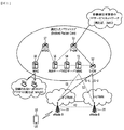
3GPP SA WG2で定義したEPS(Evolved Packet System)上位水準参照モデル(reference model)は、非ローミングケース(non−roaming case)及び多様なシナリオのローミングケース(roaming case)を含んでおり、詳細内容は、3GPP標準文書TS23.401とTS23.402で参照することができる。図1のネットワーク構造図は、これを簡略に再構成したものである。 The EPS (Evolved Packet System) high-level reference model defined by 3GPP SA WG2 includes non-roaming cases and roaming cases of various scenarios. It can be referred to in 3GPP standard documents TS23.401 and TS23.402. The network structure diagram of FIG. 1 is a simple reconfiguration of this.
図1は、進化した移動通信ネットワークの構造図である。 FIG. 1 is a structural diagram of an evolved mobile communication network.
EPCは、多様な構成要素を含むことができ、図1は、そのうち一部に該当する、S−GW(Serving Gateway)52、PDN GW(Packet Data Network Gateway)53、MME(Mobility Management Entity)51、SGSN(Serving GPRS(General Packet Radio Service) Supporting Node)、ePDG(enhanced Packet Data Gateway)を示す。 The EPC can include various components, and FIG. 1 corresponds to some of them, such as S-GW (Serving Gateway) 52, PDN GW (Packet Data Network Gateway) 53, MME (Mobility Management Entity) 51. SGSN (Serving GPRS (General Packet Radio Service) Supporting Node) and ePDG (enhanced Packet Data Gateway).
S−GW52は、無線アクセスネットワーク(RAN)とコアネットワークとの間の境界点として動作し、eNodeB22とPDN GW53との間のデータ経路を維持する機能をする要素である。また、端末(または、User Equipment:UE)がeNodeB22によりサービング(serving)される領域にわたって移動する場合、S−GW52は、ローカル移動性アンカーポイント(anchor point)の役割をする。即ち、E−UTRAN(3GPPリリース8以後で定義されるEvolved−UMTS(Universal Mobile Telecommunications System) Terrestrial Radio Access Network)内での移動性のために、S−GW52を介してパケットがルーティングされることができる。また、S−GW52は、他の3GPPネットワーク(3GPPリリース8以前に定義されるRAN、例えば、UTRANまたはGERAN(GSM(登録商標)(Global System for Mobile Communication)/EDGE(Enhanced Data rates for Global Evolution) Radio Access Network)との移動性のためのアンカーポイントとして機能することもできる。
The S-GW 52 is an element that operates as a boundary point between the radio access network (RAN) and the core network, and functions to maintain a data path between the eNodeB 22 and the PDN GW 53. In addition, when a terminal (or User Equipment: UE) moves over an area served by the eNodeB 22, the S-GW 52 serves as a local mobility anchor point. That is, because of mobility within E-UTRAN (Evolved-UMTS (Universal Mobile Communications System) Terrestrial Radio Access Network) defined in
PDN GW(または、P−GW)53は、パケットデータネットワークに向かうデータインターフェースの終端点(termination point)に該当する。PDN GW53は、政策執行特徴(policy enforcement features)、パケットフィルタリング(packet filtering)、課金サポート(charging support)などをサポートすることができる。また、3GPPネットワークと非3GPPネットワーク(例えば、I−WLAN(Interworking Wireless Local Area Network)のような信頼されないネットワーク、CDMA(Code Division Multiple Access)ネットワークやWiMaxのような信頼されるネットワーク)との移動性管理のためのアンカーポイント役割をすることができる。 The PDN GW (or P-GW) 53 corresponds to a termination point of a data interface toward the packet data network. The PDN GW 53 may support policy enforcement features, packet filtering, charging support, and the like. Also, mobility between 3GPP networks and non-3GPP networks (for example, untrusted networks such as I-WLAN (Interworking Wireless Local Area Network), CDMA (Code Division Multiple Access) networks and trusted networks such as WiMax) Can act as an anchor point for management.
図1のネットワーク構造の例示は、S−GW52とPDN GW53が別途のゲートウェイで構成されるものを示すが、二つのゲートウェイが単一ゲートウェイ構成オプション(Single Gateway Configuration Option)によって具現されることもできる。 The network structure illustrated in FIG. 1 shows that the S-GW 52 and the PDN GW 53 are configured as separate gateways, but the two gateways may be implemented by a single gateway configuration option. .
MME51は、UEのネットワーク連結に対するアクセス、ネットワークリソースの割当、トラッキング(tracking)、ページング(paging)、ローミング(roaming)及びハンドオーバなどをサポートするためのシグナリング及び制御機能を実行する要素である。MME51は、加入者及びセッション管理に関連した制御平面(control plane)機能を制御する。MME51は、数多くのeNodeB22を管理し、他の2G/3Gネットワークに対するハンドオーバのための従来のゲートウェイの選択のためのシグナリングを実行する。また、MME51は、セキュリティ過程(Security Procedures)、端末−対−ネットワークセッションハンドリング(Terminal−to−network Session Handling)、アイドル端末位置決定管理(Idle Terminal Location Management)などの機能を遂行する。
The MME 51 is an element that performs a signaling and control function for supporting access to the network connection of the UE, allocation of network resources, tracking, paging, roaming, handover, and the like. The
SGSNは、異なるアクセス3GPPネットワーク(例えば、GPRSネットワーク、UTRAN/GERAN)に対するユーザの移動性管理及び認証(authentication)といった全てのパケットデータをハンドリングする。 The SGSN handles all packet data such as user mobility management and authentication for different access 3GPP networks (eg, GPRS network, UTRAN / GERAN).
ePDGは、信頼されない非3GPPネットワーク(例えば、I−WLAN、WiFiホットスポット(hotspot)等)に対するセキュリティノードとしての役割をする。 The ePDG serves as a security node for untrusted non-3GPP networks (eg, I-WLAN, WiFi hotspot, etc.).
図1を参照して説明したように、IP能力を有する端末(または、UE)は、3GPPアクセスはもちろん非3GPPアクセスに基づいても、EPC内の多様な要素を経由して事業者(即ち、オペレータ(operator))が提供するIPサービスネットワーク(例えば、IMS)にアクセスすることができる。 As described with reference to FIG. 1, a terminal (or UE) having an IP capability can receive an operator (i.e., a 3GPP access as well as a non-3GPP access through various elements in the EPC, i.e. An IP service network (for example, IMS) provided by an operator can be accessed.
また、図1は、多様なレファレンスポイント(例えば、S1−U、S1−MME等)を示す。3GPPシステムでは、E−UTRAN及びEPCの異なる機能エンティティ(functional entity)に存在する2個の機能を連結する概念的なリンクをレファレンスポイント(reference point)と定義する。以下の表1は、図1に示すレファレンスポイントを整理したものである。表1の例示外にもネットワーク構造によって多様なレファレンスポイントが存在できる。 FIG. 1 also shows various reference points (eg, S1-U, S1-MME, etc.). In the 3GPP system, a conceptual link that connects two functions existing in different functional entities of E-UTRAN and EPC is defined as a reference point. Table 1 below summarizes the reference points shown in FIG. In addition to the examples in Table 1, various reference points may exist depending on the network structure.

図1に示すレファレンスポイントのうち、S2a及びS2bは、非3GPPインターフェースに該当する。S2aは、信頼される非3GPPアクセス及びPDNGW間の関連制御及び移動性サポートをユーザ平面に提供するレファレンスポイントである。S2bは、ePDG及びPDNGW間の関連制御及び移動性サポートをユーザ平面に提供するレファレンスポイントである。 Of the reference points shown in FIG. 1, S2a and S2b correspond to non-3GPP interfaces. S2a is a reference point that provides the user plane with related control and mobility support between trusted non-3GPP access and PDN GW. S2b is a reference point that provides the user plane with related control and mobility support between ePDG and PDNGW.
図2は、一般的にE−UTRANと一般的なEPCのアーキテクチャを示す例示図である。 FIG. 2 is an exemplary diagram illustrating a general E-UTRAN and a general EPC architecture.
図示されたように、eNodeB20は、RRC接続が活性化されている中、ゲートウェイへのルーティング、ページングメッセージのスケジューリング及び送信、ブロードキャスタチャネル(BCH)のスケジューリング及び送信、アップリンク及びダウンリンクでのリソースをUEに動的割当、eNodeB20の測定のための設定及び提供、無線ベアラ制御、無線許可制御(radio admission control)、そして、接続移動性制御などのための機能を遂行することができる。EPC内では、ページング発生、LTE_IDLE状態管理、ユーザ平面の暗号化、EPSベアラ制御、NASシグナリングの暗号化及び完全性保護機能を遂行することができる。 As shown, eNodeB 20 is responsible for routing to gateways, scheduling and transmission of paging messages, scheduling and transmission of broadcast channel (BCH), uplink and downlink resources while the RRC connection is activated. Functions for dynamic allocation to UE, setting and provision for measurement of eNodeB 20, radio bearer control, radio admission control, connection mobility control, and the like. Within the EPC, paging, LTE_IDLE state management, user plane encryption, EPS bearer control, NAS signaling encryption and integrity protection functions can be performed.
図3は、UEとeNodeBとの間の制御平面での無線インターフェースプロトコル(Radio Interface Protocol)の構造を示す例示図であり、図4は、端末と基地局との間のユーザ平面での無線インターフェースプロトコル(Radio Interface Protocol)の構造を示す他の例示図である。 FIG. 3 is an exemplary diagram illustrating a structure of a radio interface protocol (Radio Interface Protocol) in the control plane between the UE and the eNodeB, and FIG. 4 is a radio interface in the user plane between the terminal and the base station. It is another example figure which shows the structure of a protocol (Radio Interface Protocol).
前記無線インターフェースプロトコルは、3GPP無線アクセスネットワーク規格を基盤とする。前記無線インターフェースプロトコルは、水平的には物理階層(Physical Layer)、データリンク階層(Data Link Layer)、及びネットワーク階層(Network Layer)からなり、垂直的にはデータ情報送信のためのユーザ平面(User Plane)と、制御信号(Signaling)伝達のための制御平面(Control Plane)とに区分される。 The radio interface protocol is based on the 3GPP radio access network standard. The wireless interface protocol includes a physical layer (Physical Layer), a data link layer (Data Link Layer), and a network layer (Network Layer) in the horizontal direction, and a user plane (User) for data information transmission in the vertical direction. And a control plane for transmitting a control signal (Signaling).
前記プロトコル階層は、通信システムで広く知られた開放型システム間相互接続(Open System Interconnection;OSI)基準モデルの下位3個階層に基づいてL1(第1の階層)、L2(第2の階層)、L3(第3の階層)に区分されることができる。 The protocol layers are L1 (first layer) and L2 (second layer) based on the lower three layers of the Open System Interconnection (OSI) standard model widely known in communication systems. , L3 (third layer).
以下、前記図3に示す制御平面での無線プロトコルと図4に示すユーザ平面での無線プロトコルの各階層を説明する。 Hereinafter, each layer of the wireless protocol on the control plane shown in FIG. 3 and the wireless protocol on the user plane shown in FIG. 4 will be described.
第1の階層である物理階層は、物理チャネル(Physical Channel)を利用して情報転送サービス(Information Transfer Service)を提供する。前記物理階層は、上位にある媒体アクセス制御(Medium Access Control)階層とはトランスポートチャネル(Transport Channel)を介して連結されており、前記トランスポートチャネルを介して媒体アクセス制御階層と物理階層との間のデータが伝達される。そして、互いに異なる物理階層間、即ち、送信側と受信側の物理階層間は、物理チャネルを介してデータが伝達される。 The physical layer, which is the first layer, provides an information transfer service (Information Transfer Service) using a physical channel. The physical layer is connected to an upper medium access control layer via a transport channel, and the medium access control layer and the physical layer are connected via the transport channel. The data between them is transmitted. Data is transmitted between physical layers different from each other, that is, between the physical layers on the transmission side and the reception side via physical channels.
物理チャネル(Physical Channel)は、時間軸上にある複数個のサブフレームと、周波数軸上にある複数個のサブキャリア(Sub−carrier)とで構成される。ここで、一つのサブフレーム(Sub−frame)は、時間軸上に複数のシンボル(Symbol)と複数のサブキャリアとで構成される。一つのサブフレームは、複数のリソースブロック(Resource Block)で構成され、一つのリソースブロックは、複数のシンボル(Symbol)と複数のサブキャリアとで構成される。データが送信される単位時間であるTTI(Transmission Time Interval)は、1個のサブフレームに該当する1msである。 The physical channel is composed of a plurality of subframes on the time axis and a plurality of subcarriers (sub-carriers) on the frequency axis. Here, one subframe (Sub-frame) is composed of a plurality of symbols (Symbol) and a plurality of subcarriers on the time axis. One subframe is composed of a plurality of resource blocks (Resource Block), and one resource block is composed of a plurality of symbols (Symbol) and a plurality of subcarriers. TTI (Transmission Time Interval), which is a unit time for transmitting data, is 1 ms corresponding to one subframe.
前記送信側と受信側の物理階層に存在する物理チャネルは、3GPP LTEによると、データチャネルであるPDSCH(Physical Downlink Shared Channel)及びPUSCH(Physical Uplink Shared Channel)と、制御チャネルであるPDCCH(Physical Downlink Control Channel)、PCFICH(Physical Control Format Indicator Channel)、PHICH(Physical Hybrid−ARQ Indicator Channel)及びPUCCH(Physical Uplink Control Channel)と、に分けられる。 According to 3GPP LTE, the physical channels existing in the physical layers of the transmitting side and the receiving side are PDSCH (Physical Downlink Shared Channel) and PUSCH (Physical Uplink Shared Channel), which are data channels, and PDCCH (Physkin), which is a control channel. Control Channel), PCFICH (Physical Control Format Indicator Channel), PHICH (Physical Hybrid-ARQ Indicator Channel), and PUCCH (Physical Uplink) and PUCCH (Physical Uplink Channel).
サブフレームの1番目のOFDMシンボルで送信されるPCFICHは、サブフレーム内で制御チャネルの送信に使われるOFDMシンボルの数(即ち、制御領域の大きさ)に対するCFI(control format indicator)を伝送する。無線機器は、まず、PCFICH上にCFIを受信した後、PDCCHをモニタリングする。 The PCFICH transmitted in the first OFDM symbol of the subframe transmits a CFI (control format indicator) corresponding to the number of OFDM symbols (that is, the size of the control region) used for transmission of the control channel in the subframe. The wireless device first monitors the PDCCH after receiving the CFI on the PCFICH.
PDCCHと違って、PCFICHは、ブラインドデコーディングを使用せずに、サブフレームの固定されたPCFICHリソースを介して送信される。 Unlike the PDCCH, the PCFICH is transmitted via a fixed subframe PCFICH resource without using blind decoding.
PHICHは、UL HARQ(hybrid automatic repeat request)のためのACK(positive−acknowledgement)/NACK(negative−acknowledgement)信号を伝送する。無線機器により送信されるPUSCH上のUL(uplink)データに対するACK/NACK信号は、PHICH上に送信される。 The PHICH transmits an ACK (positive-acknowledgement) / NACK (negative-acknowledgement) signal for a UL HARQ (hybrid automatic repeat request). An ACK / NACK signal for UL (uplink) data on PUSCH transmitted by the wireless device is transmitted on PHICH.
PBCH(Physical Broadcast Channel)は、無線フレームの1番目のサブフレームの第2のスロットの前方部の4個のOFDMシンボルで送信される。PBCHは、無線機器が基地局と通信するときに必須なシステム情報を伝送し、PBCHを介して送信されるシステム情報をMIB(master information block)という。これと比較して、PDCCHにより指示されるPDSCH上に送信されるシステム情報をSIB(system information block)という。 PBCH (Physical Broadcast Channel) is transmitted in four OFDM symbols in the front part of the second slot of the first subframe of the radio frame. The PBCH transmits system information essential when a wireless device communicates with a base station, and system information transmitted via the PBCH is referred to as an MIB (Master Information Block). Compared with this, the system information transmitted on PDSCH instruct | indicated by PDCCH is called SIB (system information block).
PDCCHは、DL−SCH(downlink−shared channel)のリソース割当及び送信フォーマット、UL−SCH(uplink shared channel)のリソース割当情報、PCH上のページング情報、DL−SCH上のシステム情報、PDSCH上に送信されるランダムアクセス応答のような上位階層制御メッセージのリソース割当、任意のUEグループ内の個別UEに対する送信パワー制御命令のセット及びVoIP(voice over internet protocol)の活性化などを伝送することができる。複数のPDCCHが制御領域内で送信されることができ、端末は、複数のPDCCHをモニタリングすることができる。PDCCHは、一つまたは複数個の連続的なCCE(control channel elements)のアグリゲーション(aggregation)上に送信される。CCEは、無線チャネルの状態による符号化率をPDCCHに提供するために使われる論理的割当単位である。CCEは、複数のリソース要素グループ(resource element group)に対応される。CCEの数とCCEにより提供される符号化率の関係によってPDCCHのフォーマット及び可能なPDCCHのビット数が決定される。 PDCCH is transmitted on DL-SCH (downlink-shared channel) resource allocation and transmission format, UL-SCH (uplink shared channel) resource allocation information, paging information on PCH, system information on DL-SCH, and PDSCH. It is possible to transmit resource allocation of higher layer control messages such as a random access response, a set of transmission power control commands for individual UEs in an arbitrary UE group, activation of VoIP (voice over internet protocol), and the like. Multiple PDCCHs can be transmitted in the control region, and the terminal can monitor multiple PDCCHs. The PDCCH is transmitted on one or a plurality of continuous CCE (control channel elements) aggregations. The CCE is a logical allocation unit used for providing the PDCCH with a coding rate according to the state of the radio channel. A CCE corresponds to a plurality of resource element groups. The PDCCH format and the number of possible PDCCH bits are determined according to the relationship between the number of CCEs and the coding rate provided by the CCEs.
PDCCHを介して送信される制御情報をダウンリンク制御情報(downlink control information、DCI)という。DCIは、PDSCHのリソース割当(これをDLグラント(downlink grant)ともいう)、PUSCHのリソース割当(これをULグラント(uplink grant)ともいう)、任意のUEグループ内の個別UEに対する送信パワー制御命令のセット及び/またはVoIP(Voice over Internet Protocol)の活性化を含むことができる。 Control information transmitted via the PDCCH is referred to as downlink control information (DCI). DCI includes PDSCH resource allocation (also referred to as DL grant), PUSCH resource allocation (also referred to as UL grant), and a transmission power control command for individual UEs in an arbitrary UE group. And / or activation of VoIP (Voice over Internet Protocol).
第2の階層にはさまざまな階層が存在する。まず、媒体アクセス制御(Medium Access Control;MAC)階層は、多様な論理チャネル(Logical Channel)を多様なトランスポートチャネルにマッピングさせる役割をし、また、複数の論理チャネルを一つのトランスポートチャネルにマッピングさせる論理チャネル多重化(Multiplexing)の役割を遂行する。MAC階層は、上位階層であるRLC階層とは論理チャネル(Logical Channel)を介して接続されており、論理チャネルは、大いに、送信される情報の種類によって、制御平面(Control Plane)の情報を送信する制御チャネル(Control Channel)と、ユーザ平面(User Plane)の情報を送信するトラフィックチャネル(Traffic Channel)と、に分けられる。 Various hierarchies exist in the second hierarchy. First, the medium access control (MAC) layer serves to map various logical channels (Logical Channel) to various transport channels, and also maps a plurality of logical channels to one transport channel. It performs the role of logical channel multiplexing. The MAC layer is connected to the RLC layer, which is an upper layer, via a logical channel, and the logical channel transmits control plane information depending on the type of information to be transmitted. The control channel (Control Channel) to be transmitted and the traffic channel (Traffic Channel) to transmit user plane information (Traffic Channel).
第2の階層の無線リンク制御(Radio Link Control;RLC)階層は、上位階層から受信したデータを分割(Segmentation)及び連結(Concatenation)して下位階層が無線区間へのデータの送信に適合するようにデータの大きさを調節する役割を遂行する。また、各々の無線ベアラ(Radio Bearer;RB)が要求する多様なQoSが保障可能にするために、TM(Transparent Mode、透明モード)、UM(Un−acknowledged Mode、無応答モード)、及びAM(Acknowledged Mode、応答モード)の三つの動作モードを提供している。特に、AM RLCは、信頼性のあるデータ送信のために、自動反復及び要求(Automatic Repeat and Request;ARQ)機能を介した再送信機能を遂行している。 The radio link control (RLC) layer of the second layer divides the data received from the upper layer (Segmentation) and connects (Concatenation) so that the lower layer is suitable for data transmission to the radio section. It performs the role of adjusting the data size. In addition, in order to ensure various QoS required by each radio bearer (RB), TM (Transparent Mode, transparent mode), UM (Un-acknowledged mode), and AM ( (Acknowledged Mode, response mode). In particular, the AM RLC performs a retransmission function through an automatic repeat and request (ARQ) function for reliable data transmission.
第2の階層のパケットデータ収束(Packet Data Convergence Protocol;PDCP)階層は、IPv4やIPv6のようなIPパケット送信時、帯域幅が小さい無線区間で効率的に送信するために相対的に大きさが大きくて不要な制御情報を含んでいるIPパケットヘッダサイズを減らすヘッダ圧縮(Header Compression)機能を遂行する。これはデータのヘッダ(Header)部分で必ず必要な情報のみを送信するようにすることで、無線区間の送信効率を増加させる役割をする。また、LTEシステムでは、PDCP階層がセキュリティ(Security)機能も実行し、これは第3者のデータ盗聴を防止する暗号化(Ciphering)と第3者のデータ操作を防止する完全性保護(Integrity protection)とで構成される。 The packet data convergence protocol (PDCP) layer of the second layer has a relatively large size in order to transmit efficiently in a wireless section with a small bandwidth when transmitting an IP packet such as IPv4 or IPv6. It performs a header compression function that reduces the size of an IP packet header that contains large and unnecessary control information. This serves to increase the transmission efficiency of the wireless section by transmitting only necessary information in the header of the data. In the LTE system, the PDCP layer also performs a security function, which is encryption for preventing third party data eavesdropping and integrity protection for preventing third party data manipulation. ).
第3階層の最も上部に位置した無線リソース制御(Radio Resource Control;以下、RRCと略称する)階層は、制御平面でのみ定義され、無線ベアラ(Radio Bearer;RBと略称する)の設定(Configuration)、再設定(Re−configuration)及び解除(Release)と関連して論理チャネル、トランスポートチャネル、及び物理チャネルの制御を担当する。このとき、RBは、端末とE−UTRANとの間のデータ伝達のために、第2の階層により提供されるサービスを意味する。 The radio resource control (Radio Resource Control; hereinafter abbreviated as RRC) layer located at the top of the third hierarchy is defined only in the control plane, and is configured as a radio bearer (abbreviated as RB). Responsible for control of logical channels, transport channels, and physical channels in association with re-configuration and release. At this time, the RB means a service provided by the second layer for data transmission between the terminal and the E-UTRAN.
前記端末のRRCと無線ネットワークのRRC階層との間にRRC接続(RRC connection)がある場合、端末は、RRC接続状態(Connected Mode)になり、そうでない場合、RRCアイドル状態(Idle Mode)になる。 If there is an RRC connection between the RRC of the terminal and the RRC layer of the radio network, the terminal enters an RRC connected state (Connected Mode); otherwise, the terminal enters an RRC idle state (Idle Mode). .
以下、端末のRRC状態(RRC state)とRRC接続方法に対して説明する。RRC状態とは、端末のRRCがE−UTRANのRRCと論理的接続(logical connection)されているかどうかを意味し、接続されている場合はRRC_CONNECTED状態(state)といい、接続されていない場合はRRC_IDLE状態という。RRC_CONNECTED状態の端末は、RRC接続が存在するため、E−UTRANは、該当端末の存在をセル単位で把握することができ、したがって、端末を効果的に制御することができる。それに対し、RRC_IDLE状態の端末は、E−UTRANが端末の存在を把握することはできず、セルより大きい地域単位であるTA(Tracking Area)単位に核心ネットワークが管理する。即ち、RRC_IDLE状態の端末は、セルに比べて大きい地域単位に該当端末の存在可否のみが把握され、音声やデータのような通常の移動通信サービスを受けるためには、該当端末がRRC_CONNECTED状態に移動しなければならない。各TAは、TAI(Tracking area identity)を介して区分される。端末は、セルで放送(broadcasting)される情報であるTAC(Tracking area code)を介してTAIを構成することができる。 Hereinafter, the RRC state (RRC state) of the terminal and the RRC connection method will be described. The RRC state means whether or not the terminal RRC is logically connected to the E-UTRAN RRC, and is referred to as an RRC_CONNECTED state (state). It is called RRC_IDLE state. Since a terminal in the RRC_CONNECTED state has an RRC connection, the E-UTRAN can grasp the presence of the corresponding terminal in units of cells, and thus can effectively control the terminal. On the other hand, the terminal in the RRC_IDLE state cannot be recognized by the E-UTRAN, and is managed by the core network in units of TA (Tracking Area), which is an area unit larger than the cell. That is, a terminal in the RRC_IDLE state only knows whether or not the corresponding terminal exists in a region unit larger than the cell, and the corresponding terminal moves to the RRC_CONNECTED state in order to receive a normal mobile communication service such as voice or data. Must. Each TA is classified through a TAI (Tracking area identity). The terminal can configure the TAI through a TAC (Tracking area code) that is information broadcast in a cell.
ユーザが端末の電源を最初にオンした時、端末は、まず、適切なセルを探索した後、該当セルでRRC接続を確立し、核心ネットワークに端末の情報を登録する。この後、端末は、RRC_IDLE状態にとどまる。RRC_IDLE状態にとどまる端末は、必要によって、セルを(再)選択し、システム情報(System information)やページング情報を確認する。これをセルにキャンプオン(Camp on)するという。RRC_IDLE状態にとどまっていた端末は、RRC接続を確立する必要がある時はじめてRRC接続過程(RRC connection procedure)を介してE−UTRANのRRCとRRC接続を確立し、RRC_CONNECTED状態に移動する。RRC_IDLE状態にあった端末がRRC接続を確立する必要がある場合は多様であり、例えば、ユーザの通話試みなどの理由でアップリンクデータ送信が必要であり、またはE−UTRANからページングメッセージを受信した場合、これに対する応答メッセージ送信などを挙げることができる。 When a user first turns on a terminal, the terminal first searches for an appropriate cell, establishes an RRC connection in the corresponding cell, and registers terminal information in the core network. After this, the terminal remains in the RRC_IDLE state. The terminal that remains in the RRC_IDLE state (re) selects a cell as necessary, and confirms system information and paging information. This is called camp on the cell. The terminal staying in the RRC_IDLE state establishes the RRC connection with the E-UTRAN through the RRC connection procedure for the first time when the RRC connection needs to be established, and moves to the RRC_CONNECTED state. There are various cases where a terminal in the RRC_IDLE state needs to establish an RRC connection. For example, uplink data transmission is necessary for a reason such as a user's call attempt or a paging message is received from E-UTRAN. In this case, a response message can be transmitted.
前記RRC階層の上位に位置するNAS(Non−Access Stratum)階層は、セッション管理(Session Management)と移動性管理(Mobility Management)等の機能を遂行する。 A NAS (Non-Access Stratum) layer located above the RRC layer performs functions such as session management and mobility management.
以下、図3に示すNAS階層に対して詳細に説明する。 Hereinafter, the NAS hierarchy shown in FIG. 3 will be described in detail.
NAS階層に属するESM(Evolved Session Management)は、Default Bearer管理及びDedicated Bearer管理のような機能を遂行し、端末がネットワークからPSサービスを利用するための制御を担当する。Default Bearerリソースは、特定Packet Data Network(PDN)に最初接続する時またはネットワークに接続される時、ネットワークから割当を受けるという特徴を有する。このとき、ネットワークは、端末がデータサービスを使用することができるように端末が使用可能なIPアドレスを割り当て、また、default bearerのQoSを割り当てる。LTEでは、大いに、データ送受信のための特定帯域幅を保障するGBR(Guaranteed bit rate)QoS特性を有するbearerと、帯域幅の保障無しでBest effort QoS特性を有するNon−GBR bearerの2種類をサポートする。Default bearerの場合、Non−GBR bearerの割当を受ける。Dedicated bearerの場合は、GBRまたはNon−GBRのQoS特性を有するbearerの割当を受けることができる。 An ESM (Evolved Session Management) belonging to the NAS layer performs functions such as Default Bearer management and Dedicated Bearer management, and is responsible for control for the terminal to use the PS service from the network. The default bearer resource is characterized in that it is allocated from the network when it first connects to a specific packet data network (PDN) or when it is connected to the network. At this time, the network assigns an IP address that the terminal can use so that the terminal can use the data service, and assigns a QoS of the default bearer. LTE greatly supports two types of bearer having a GBR (guaranteed bit rate) QoS characteristic that guarantees a specific bandwidth for data transmission and reception and non-GBR bearer having a best effort QoS characteristic without guaranteeing the bandwidth. To do. In the case of the default bearer, the non-GBR bearer is assigned. In the case of a dedicated bearer, a bearer having a QoS characteristic of GBR or Non-GBR can be assigned.
ネットワークから端末に割り当てたbearerをEPS(evolved packet service)bearerといい、EPS bearerを割当する時、ネットワークは、一つのIDを割り当てるようになる。これをEPS Bearer IDという。一つのEPS bearerは、MBR(maximum bit rate)とGBR(guaranteed bit rate)またはAMBR(Aggregated maximum bit rate)のQoS特性を有する。 The bearer assigned to the terminal from the network is called an EPS (evolved packet service) bearer. When the EPS bearer is assigned, the network assigns one ID. This is called EPS Bearer ID. One EPS bearer has the QoS characteristics of MBR (maximum bit rate) and GBR (guaranteed bit rate) or AMBR (Aggregated maximum bit rate).
一方、図3において、NAS階層下に位置するRRC階層、RLC階層、MAC階層、PHY階層を束ねてアクセス階層(Access Stratum:AS)とも呼ばれる。 On the other hand, in FIG. 3, the RRC layer, RLC layer, MAC layer, and PHY layer located below the NAS layer are collectively referred to as an access stratum (AS).
図5aは、3GPP LTEでランダムアクセス過程を示す流れ図である。 FIG. 5a is a flowchart illustrating a random access process in 3GPP LTE.
ランダムアクセス過程は、UE10が基地局、即ち、eNodeB20とUL同期を得たり、UL無線リソースの割当を受けるために使われる。
The random access process is used when the
UE10は、ルートインデックス(root index)とPRACH(physical random access channel)設定インデックス(設定index)をeNodeB20から受信する。各セル毎にZC(Zadoff−Chu)シーケンスにより定義される64個の候補(candidate)ランダムアクセスプリアンブルがあり、ルートインデックスは、端末が64個の候補ランダムアクセスプリアンブルを生成するための論理的インデックスである。
The
ランダムアクセスプリアンブルの送信は、各セル毎に特定時間及び周波数リソースに限定される。PRACH設定インデックスは、ランダムアクセスプリアンブルの送信が可能な特定サブフレームとプリアンブルフォーマットを指示する。 Transmission of the random access preamble is limited to a specific time and frequency resource for each cell. The PRACH setting index indicates a specific subframe and preamble format in which a random access preamble can be transmitted.
UE10は、任意に選択されたランダムアクセスプリアンブルをeNodeB20に送信する。UE10は、64個の候補ランダムアクセスプリアンブルのうち一つを選択する。そして、PRACH設定インデックスにより該当するサブフレームを選択する。UE10は、選択されたランダムアクセスプリアンブルを選択されたサブフレームに送信する。
The
前記ランダムアクセスプリアンブルを受信したeNodeB20は、ランダムアクセス応答(random access response、RAR)をUE10に送る。ランダムアクセス応答は、2ステップに検出される。まず、UE10は、RA−RNTI(random access−RNTI)でマスキングされたPDCCHを検出する。UE10は、検出されたPDCCHにより指示されるPDSCH上にMAC(Medium Access Control)PDU(Protocol Data Unit)内のランダムアクセス応答を受信する。
The
図5bは、無線リソース制御(RRC)階層での接続過程を示す。 FIG. 5b shows a connection process in the radio resource control (RRC) layer.
図5bに示すように、RRC接続可否によるRRC状態が示されている。前記RRC状態とは、UE10のRRC階層のエンティティ(entity)がeNodeB20のRRC階層のエンティティと論理的接続(logical connection)されているかどうかを意味し、接続されている場合をRRC接続状態(connected state)といい、接続されていない状態をRRCアイドル状態(idle state)という。
As shown in FIG. 5b, an RRC state depending on whether the RRC connection is possible is shown. The RRC state means whether an entity in the RRC layer of the
前記接続状態(Connected state)のUE10は、RRC接続(connection)が存在するため、E−UTRANは、該当端末の存在をセル単位で把握することができ、したがって、UE10を効果的に制御することができる。それに対し、アイドル状態(idle state)のUE10は、eNodeB20が把握することはできず、セルより大きい地域単位であるトラッキング地域(Tracking Area)単位に核心ネットワーク(Core Network)が管理する。前記トラッキング地域(Tracking Area)は、セルの集合単位である。即ち、アイドル状態(idle state)のUE10は、大きい地域単位に存在可否のみが把握され、音声やデータのような通常の移動通信サービスを受けるためには、端末は、接続状態(connected state)に切り替えしなければならない。
Since the
ユーザがUE10の電源を最初にオンにした時、前記UE10は、まず、適切なセルを探索した後、該当セルでアイドル状態(idle state)にとどまる。前記アイドル状態(idle state)のUE10は、RRC接続を確立する必要がある時になって初めてRRC接続過程(RRC connection procedure)を介してeNodeB20のRRC階層とRRC接続を確立することでRRC接続状態(connected state)に切り替える。
When the user first turns on the
前記アイドル状態(Idle state)の端末がRRC接続を確立する必要がある場合は多様であり、例えば、ユーザの通話試みまたはアップリンクデータ送信などが必要な場合、またはEUTRANからページングメッセージを受信した場合、これに対する応答メッセージ送信などを挙げることができる。 There are various cases where an idle state terminal needs to establish an RRC connection, for example, when a user call attempt or uplink data transmission is required, or when a paging message is received from EUTRAN Response message transmission to this can be mentioned.
アイドル状態(idle state)のUE10が前記eNodeB20とRRC接続を確立するためには、前記したように、RRC接続過程(RRC connection procedure)を進行しなければならない。RRC接続過程は、大いに、UE10がeNodeB20にRRC接続要求(RRC connection request)メッセージ送信する過程、eNodeB20がUE10にRRC接続設定(RRC connection setup)メッセージを送信する過程、そしてUE10がeNodeB20にRRC接続設定完了(RRC connection setup complete)メッセージを送信する過程を含む。このような過程に対して図5bを参照してより詳細に説明すると、下記の通りである。
In order for the
1)アイドル状態(Idle state)のUE10は、通話試み、データ送信試み、またはeNodeB20のページングに対する応答などの理由でRRC接続を確立しようとする場合、まず、前記UE10は、RRC接続要求(RRC connection request)メッセージをeNodeB20に送信する。
1) When the
2)前記UE10からRRC接続要求メッセージを受信すると、前記eNB10は、無線リソースが十分な場合、前記UE10のRRC接続要求を受諾し、応答メッセージであるRRC接続設定(RRC connection setup)メッセージを前記UE10に送信する。
2) When receiving the RRC connection request message from the
3)前記UE10が前記RRC接続設定メッセージを受信すると、前記eNodeB20にRRC接続設定完了(RRC connection setup complete)メッセージを送信する。前記UE10がRRC接続設定メッセージを成功的に送信すると、そのとき、前記UE10は、eNodeB20とRRC接続を確立するようになってRRC接続モードに切り替える。
3) When the
一方、UE10がユーザ平面のデータ送信を目的としてRRC接続要求をする時、前記ネットワーク、例えば、基地局(即ち、eNodeB)が混雑状態の場合はこれを拒絶することができる。
On the other hand, when the
ネットワーク過負荷及び混雑状況でUEの特定アプリケーション別にサービス差別化するための方案が必要である。しかし、従来技術ではこれを具現することができる方案がない。 There is a need for a method for differentiating services according to specific applications of UE in a network overload and congestion situation. However, the prior art has no way of realizing this.
したがって、本明細書の一開示は、前述した問題点を解決することができる方案を提示することを目的とする。 Therefore, an object of one disclosure of the present specification is to provide a method capable of solving the above-described problems.
前記のような目的を達成するために、本明細書の一開示は、ユーザ装置(user equipment:UE)によりネットワークアクセスを試みる方法を提供する。前記方法は、ACDC(Application specific Congestion control for Data Communication)が設定されている場合、ネットワークアクセスを試みるアプリケーションの関連情報を上位階層から取得するステップ;前記取得されたアプリケーションの関連情報に基づいて、ACDCカテゴリを決定するステップ;及び、前記決定されたACDCカテゴリに基づいて、ACDC検査を実行するステップ;を含む。ここで、前記ACDC検査によってアプリケーション別にネットワークアクセス試みが遮断(barred)されたり許容される。 In order to achieve the above object, one disclosure of the present specification provides a method of attempting network access by a user equipment (UE). In the method, when an application specific control for data communication (ACDC) is set, the related information of an application attempting network access is acquired from an upper layer; based on the acquired related information of the application, the ACDC Determining a category; and performing an ACDC test based on the determined ACDC category. Here, network access attempts are barred or allowed by application by the ACDC inspection.
前記アプリケーション関連情報は、前記アプリケーションのグループ、カテゴリ、優先順位、情報及びIDのうち一つ以上を含む。 The application related information includes one or more of a group, a category, a priority, information, and an ID of the application.
前記ACDC検査は、特定のアプリケーション単位別に定義されるACDC設定情報に基づいて実行される。 The ACDC inspection is performed based on ACDC setting information defined for each specific application unit.
前記ACDC設定情報は、特定のアプリケーション単位別に定義される遮断比率、遮断ファクタ、遮断時間、ローミング情報、ACBスキップ設定を含む。 The ACDC setting information includes a blocking ratio, a blocking factor, a blocking time, roaming information, and an ACB skip setting defined for each specific application unit.
前記特定のアプリケーション単位は、アプリケーションのグループ、カテゴリ、優先順位、または情報/ID単位である。 The specific application unit is an application group, category, priority, or information / ID unit.
前記ACDCカテゴリを決定するステップでは、前記上位階層から取得されるアプリケーションの関連情報が複数個数である場合、最も高い等級のアプリケーション関連情報または最も低い等級のアプリケーション関連情報に基づいて、ACDCカテゴリを決定する。 In the step of determining the ACDC category, when there are a plurality of pieces of application related information acquired from the upper layer, the ACDC category is determined based on the highest grade application related information or the lowest grade application related information. To do.
前記ACDCカテゴリを決定するステップでは、前記上位階層から取得されるアプリケーションの関連情報が複数個数である場合、複数のACDCカテゴリを決定する。 In the step of determining the ACDC category, a plurality of ACDC categories are determined when there are a plurality of pieces of related information of applications acquired from the upper layer.
前記ACDC検査を実行するステップでは、前記決定された複数のACDCカテゴリのうち、最も高い等級のアプリケーション関連情報または最も低い等級のアプリケーション関連情報に基づいて、ACDC検査が実行される。 In the step of performing the ACDC inspection, the ACDC inspection is performed based on the highest grade application related information or the lowest grade application related information among the determined plurality of ACDC categories.
また、前記のような目的を達成するために、本明細書の一開示は、ネットワークアクセスを試みるユーザ装置(user equipment:UE)を提供する。前記ユーザ装置は、送受信部;及び、前記送受信部を制御するプロセッサ;を含む。前記プロセッサは、ACDC(Application specific Congestion control for Data Communication)が設定されている場合、ネットワークアクセスを試みるアプリケーションの関連情報を取得する過程;前記取得されたアプリケーションの関連情報に基づいて、ACDCカテゴリを決定する過程;及び、前記決定されたACDCカテゴリに基づいて、ACDC検査する過程;を実行する。ここで、プロセッサは、前記ACDC検査によってアプリケーション別にネットワークアクセス試みを遮断(barred)したり、許容する。
例えば、本願発明は以下の項目を提供する。
(項目1)
ユーザ装置(user equipment:UE)によりネットワークアクセスを試みる方法であって、
ACDC(Application specific Congestion control for Data Communication)が設定されている場合、ネットワークアクセスを試みるアプリケーションの関連情報を上位階層から取得するステップ;
前記取得されたアプリケーションの関連情報に基づいて、ACDCカテゴリを決定するステップ;及び、
前記決定されたACDCカテゴリに基づいて、ACDC検査を実行するステップ;を含み、
前記ACDC検査によってアプリケーション別にネットワークアクセス試みが遮断(barred)されたり許容されることを特徴とするネットワークアクセス遮断方法。
(項目2)
前記アプリケーション関連情報は、
前記アプリケーションのグループ、カテゴリ、優先順位、情報及びIDのうち一つ以上を含むことを特徴とする項目1に記載のネットワークアクセス遮断方法。
(項目3)
前記ACDC検査は、
特定のアプリケーション単位別に定義されるACDC設定情報に基づいて実行されることを特徴とする項目1に記載のネットワークアクセス遮断方法。
(項目4)
前記ACDC設定情報は、
特定のアプリケーション単位別に定義される遮断比率、遮断ファクタ、遮断時間、ローミング情報、ACBスキップ設定を含むことを特徴とする項目3に記載のネットワークアクセス遮断方法。
(項目5)
前記特定のアプリケーション単位は、
アプリケーションのグループ、カテゴリ、優先順位、または情報/ID単位であることを特徴とする項目3に記載のネットワークアクセス遮断方法。
(項目6)
前記ACDCカテゴリを決定するステップでは、
前記上位階層から取得されるアプリケーションの関連情報が複数個数である場合、
最も高い等級のアプリケーション関連情報または最も低い等級のアプリケーション関連情報に基づいて、ACDCカテゴリを決定することを特徴とする項目1に記載のネットワークアクセス遮断方法。
(項目7)
前記ACDCカテゴリを決定するステップでは、
前記上位階層から取得されるアプリケーションの関連情報が複数個数である場合、複数のACDCカテゴリを決定することを特徴とする項目1に記載のネットワークアクセス遮断方法。
(項目8)
前記ACDC検査を実行するステップでは、
前記決定された複数のACDCカテゴリのうち、最も高い等級のアプリケーション関連情報または最も低い等級のアプリケーション関連情報に基づいて、ACDC検査が実行されることを特徴とする項目7に記載のネットワークアクセス遮断方法。
(項目9)
ネットワークアクセスを試みるユーザ装置(user equipment:UE)であって、
送受信部;及び、
前記送受信部を制御するプロセッサ;であり、前記プロセッサは、
ACDC(Application specific Congestion control for Data Communication)が設定されている場合、ネットワークアクセスを試みるアプリケーションの関連情報を取得する過程;
前記取得されたアプリケーションの関連情報に基づいて、ACDCカテゴリを決定する過程;及び、
前記決定されたACDCカテゴリに基づいて、ACDC検査する過程;を実行し、
ここで、プロセッサは、前記ACDC検査によってアプリケーション別にネットワークアクセス試みを遮断(barred)したり、許容することを特徴とするユーザ装置。
(項目10)
前記アプリケーション関連情報は
前記アプリケーションのグループ、カテゴリ、優先順位、情報及びIDのうち一つ以上を含むことを特徴とする項目9に記載のユーザ装置。
(項目11)
前記ACDC検査は、
特定のアプリケーション単位別に定義されるACDC設定情報に基づいて実行されることを特徴とする項目9に記載のユーザ装置。
(項目12)
前記ACDC設定情報は、
特定のアプリケーション単位別に定義される遮断比率、遮断ファクタ、遮断時間、ローミング情報、ACBスキップ設定を含むことを特徴とする項目11に記載のユーザ装置。
(項目13)
前記特定のアプリケーション単位は、
アプリケーションのグループ、カテゴリ、優先順位、または情報/ID単位であることを特徴とする項目11に記載のユーザ装置。
In order to achieve the above object, one disclosure of the present specification provides a user equipment (UE) that attempts network access. The user device includes a transmission / reception unit; and a processor that controls the transmission / reception unit. When the application specific control for data communication (ACDC) is set, the processor acquires related information of an application attempting network access; determines an ACDC category based on the acquired related information of the application; Performing an ACDC check based on the determined ACDC category. Here, the processor blocks or allows a network access attempt for each application through the ACDC check.
For example, the present invention provides the following items.
(Item 1)
A method of attempting network access by a user equipment (UE) comprising:
A step of acquiring related information of an application attempting network access from an upper layer when an application specific con- trol control for data communication (ACDC) is set;
Determining an ACDC category based on the acquired application related information; and
Performing an ACDC test based on the determined ACDC category;
A network access blocking method, wherein network access attempts are barred or permitted for each application by the ACDC inspection.
(Item 2)
The application related information is:
The network access blocking method according to
(Item 3)
The ACDC inspection includes
2. The network access blocking method according to
(Item 4)
The ACDC setting information includes
4. The network access blocking method according to
(Item 5)
The specific application unit is
(Item 6)
In the step of determining the ACDC category,
When there is a plurality of related information of applications acquired from the upper layer,
The network access blocking method according to
(Item 7)
In the step of determining the ACDC category,
2. The network access blocking method according to
(Item 8)
In the step of performing the ACDC inspection,
8. The network access blocking method according to
(Item 9)
A user equipment (UE) attempting network access,
A transceiver unit; and
A processor for controlling the transceiver unit; and
A process of acquiring related information of an application that attempts network access when ACDC (Application specific Connection control for Data Communication) is set;
Determining an ACDC category based on the obtained related information of the application; and
Performing an ACDC examination based on the determined ACDC category;
Here, the processor blocks or allows a network access attempt for each application through the ACDC inspection, or allows the user apparatus.
(Item 10)
The application related information is
(Item 11)
The ACDC inspection includes
10. The user apparatus according to
(Item 12)
The ACDC setting information includes
(Item 13)
The specific application unit is
本明細書の開示によると、前述した従来技術の問題点が解決される。 According to the disclosure of the present specification, the above-described problems of the prior art are solved.
本発明は、UMTS(Universal Mobile Telecommunication System)及びEPC(Evolved Packet Core)を基準にして説明するか、このような通信システムにのみ限定されるものではなく、本発明の技術的思想が適用されることができる全ての通信システム及び方法にも適用されることができる。 The present invention will be described based on UMTS (Universal Mobile Telecommunication System) and EPC (Evolved Packet Core), or is not limited to such a communication system, and the technical idea of the present invention is applied. It can also be applied to all communication systems and methods that can.
本明細書で使われる技術的用語は、単に特定の実施例を説明するために使われたものであり、本発明を限定するものではないことを留意しなければならない。また、本明細書で使われる技術的用語は、本明細書で特別に他の意味で定義されない限り、本発明が属する技術分野において、通常の知識を有する者により一般的に理解される意味で解釈されなければならず、過度に包括的な意味または過度に縮小された意味で解釈されてはならない。また、本明細書で使われる技術的な用語が本発明の思想を正確に表現することができない技術的な用語である場合、当業者が正確に理解することができる技術的用語に変えて理解しなければならない。また、本発明で使われる一般的な用語は、辞書の定義によってまたは前後文脈によって解釈されなければならず、過度に縮小された意味で解釈されてはならない。 It should be noted that the terminology used herein is for the purpose of describing particular embodiments only and is not intended to be limiting of the invention. In addition, technical terms used in this specification are defined in the technical field to which the present invention belongs unless otherwise specifically defined in this specification. It must be interpreted and should not be interpreted in an overly comprehensive or overly reduced sense. In addition, when technical terms used in the present specification are technical terms that cannot accurately express the idea of the present invention, they are replaced with technical terms that can be accurately understood by those skilled in the art. Must. Also, the general terms used in the present invention must be interpreted according to the dictionary definition or according to the context before and after, and not in an excessively reduced sense.
また、本明細書で使われる単数の表現は、文脈上、明白に異なる意味ではない限り、複数の表現を含む。本出願において、構成されるまたは有するなどの用語は、明細書上に記載された多様な構成要素、または多様なステップを必ず全て含むと解釈されてはならず、そのうち一部構成要素または一部ステップは含まれない場合もあり、または追加的な構成要素またはステップをさらに含む場合もあると解釈されなければならない。 Also, singular expressions used herein include the plural unless the context clearly indicates otherwise. In this application, terms such as composed or possessed should not be construed to necessarily include all the various components or various steps described in the specification, some of which may be It should be construed that a step may not be included, or may include additional components or steps.
また、本明細書で使われる第1及び第2などのように序数を含む用語は、多様な構成要素の説明に使われることができるが、前記構成要素は、前記用語により限定されてはならない。前記用語は、一つの構成要素を他の構成要素から区別する目的としてのみ使われる。例えば、本発明の権利範囲を外れない限り、第1の構成要素は第2の構成要素と命名することができ、同様に、第2の構成要素も第1の構成要素と命名することができる。 In addition, terms including ordinal numbers such as first and second used in this specification can be used to describe various components, but the components should not be limited by the terms. . The terms are used only for the purpose of distinguishing one component from another. For example, the first component can be named as the second component, and similarly, the second component can be named as the first component, as long as they do not depart from the scope of the present invention. .
一構成要素が他の構成要素に連結されているまたは接続されていると言及された場合は、該当他の構成要素に直接的に連結されており、または接続されていることもあるが、中間に他の構成要素が存在することもある。それに対し、一構成要素が他の構成要素に直接連結されているまたは直接接続されていると言及された場合は、中間に他の構成要素が存在しないと理解しなげればならない。 When a component is referred to as being linked or connected to another component, it may be directly linked to or connected to that other component, There may be other components. On the other hand, when it is mentioned that one component is directly connected to or directly connected to another component, it must be understood that there is no other component in between.
以下、添付図面を参照して本発明による好ましい実施例を詳細に説明し、図面符号に関係なしに同じまたは類似の構成要素は同じ参照番号を付与し、これに対する重複説明は省略する。また、本発明を説明するにあたって、関連した公知技術に対する具体的な説明が本発明の要旨を不明にすると判断される場合、その詳細な説明を省略する。また、添付図面は、本発明の思想を容易に理解することができるようにするためのものであり、添付図面により本発明の思想が制限されると解釈されてはならないことを留意しなければならない。本発明の思想は、添付図面外に全ての変更、均等物乃至代替物にまで拡張されると解釈されなければならない。 Hereinafter, preferred embodiments of the present invention will be described in detail with reference to the accompanying drawings, wherein the same or similar components are given the same reference numerals regardless of the reference numerals, and the duplicated description thereof will be omitted. Further, in describing the present invention, when it is determined that a specific description of a related known technique makes the gist of the present invention unclear, a detailed description thereof will be omitted. Further, the accompanying drawings are provided so that the idea of the present invention can be easily understood, and it should be noted that the accompanying drawings should not be construed as limiting the idea of the present invention. Don't be. The idea of the present invention should be construed to be extended to all modifications, equivalents and alternatives outside the accompanying drawings.
添付図面には例示的にUE(User Equipment)が示されているが、図示された前記UEは、端末(Terminal)、ME(Mobile Equipment)などの用語で呼ばれる場合もある。また、前記UEは、ノートブック、携帯電話、PDA、スマートフォン(Smart Phone)、マルチメディア機器などのように携帯可能な機器であり、またはPC及び車両搭載装置のように携帯不可能な機器である。 In the accompanying drawings, a UE (User Equipment) is exemplarily shown, but the illustrated UE may be referred to by a term such as a terminal (Terminal) or a ME (Mobile Equipment). The UE is a portable device such as a notebook, a mobile phone, a PDA, a smartphone (Smart Phone), or a multimedia device, or a non-portable device such as a PC or a vehicle-mounted device. .
用語の定義 Definition of terms
以下、図面を参照して説明する前に、本発明の理解を容易にするために、本明細書で使われる用語を簡略に定義する。 Hereinafter, in order to facilitate understanding of the present invention, terms used in this specification will be defined briefly before they are described with reference to the drawings.
UMTS:Universal Mobile Telecommunication Systemの略字であって、3世代移動通信の核心ネットワークを意味する。 UMTS: Abbreviation for Universal Mobile Telecommunication System, which means the core network of 3G mobile communication.
UE/MS:User Equipment/Mobile Station、端末装置を意味する。 UE / MS: User Equipment / Mobile Station, which means a terminal device.
EPS:Evolved Packet Systemの略字であって、LTE(Long Term Evolution)ネットワークをサポートするコアネットワークを意味する。UMTSが進化した形態のネットワーク。 EPS: Abbreviated Evolved Packet System, which means a core network that supports LTE (Long Term Evolution) networks. A network in the form of an evolution of UMTS.
PDN(Public Data Network):サービスを提供するサーバが位置した独立的なネットワーク。 PDN (Public Data Network): An independent network in which servers providing services are located.
PDN connection:端末からPDNへの接続、即ち、ipアドレスで表現される端末とAPNで表現されるPDNとの連関(接続)。 PDN connection: connection from a terminal to a PDN, that is, an association (connection) between a terminal expressed by an ip address and a PDN expressed by an APN.
PDN−GW(Packet Data Network Gateway):UE IP address allocation、Packet screening&filtering、Charging data collection機能を遂行するEPSネットワークのネットワークノード。 PDN-GW (Packet Data Network Gateway): A network node of an EPS network that performs UE IP address allocation, Packet screening & filtering, and Charging data collection functions.
Serving GW(Serving Gateway):移動性担当(Mobility anchor)、パケットルーティング(Packet routing)、アイドルモードパケットバッファリング(Idleモードpacket buffering)、Triggering MME to page UE機能を遂行するEPSネットワークのネットワークノード。 Serving GW (Serving Gateway): A network node of an EPS network that performs a mobility anchor, packet routing, idle mode packet buffering, and triggering MME to page UE functions.
PCRF(政策and Charging Rule Function):サービス流れ(flow)別に差別化されたQoS及び課金政策を動的(dynamic)に適用するための政策決定(政策decision)を実行するEPSネットワークのノード。 PCRF (Policy and Charging Rule Function): A node of an EPS network that performs policy decision for dynamically applying QoS and charging policy differentiated according to service flow.
APN(Access Point Name):ネットワークで管理する接続ポイントの名称であって、UEに提供される。即ち、PDNを指称したり区分する文字列。要求したサービスやネットワーク(PDN)に接続するためには該当P−GWを経由するようになり、このP−GWをさがすことができるようにネットワーク内で予め定義した名称(文字列)。例えば、internet.mnc012.mcc345.gprs APN (Access Point Name): The name of the connection point managed in the network and provided to the UE. That is, a character string that designates or distinguishes PDN. In order to connect to the requested service or network (PDN), a name (character string) is defined in advance in the network so that the P-GW can be searched. For example, Internet. mnc012. mcc345. gprs
TEID(Tunnel Endpoint Identifier):ネットワーク内のノード間に設定されたトンネルのEnd point ID、各UEのbearer単位に区間別に設定される。 TEID (Tunnel Endpoint Identifier): End point ID of a tunnel set between nodes in the network, set for each bearer unit of each UE.
NodeB:UMTSネットワークの基地局であって、屋外に設置され、セルカバレッジ規模はマクロセルに該当する。 NodeB: A base station of a UMTS network, which is installed outdoors and has a cell coverage size corresponding to a macro cell.
eNodeB:EPS(Evolved Packet System)の基地局であって、屋外に設置され、セルカバレッジ規模はマクロセルに該当する。 eNodeB: EPS (Evolved Packet System) base station, which is installed outdoors and has a cell coverage size corresponding to a macro cell.
(e)NodeB:NodeBとeNodeBを指称する用語である。 (E) NodeB: a term that refers to NodeB and eNodeB.
MME:Mobility Management Entityの略字であって、UEに対するセッションと移動性を提供するためにEPS内で各エンティティを制御する役割をする。 MME: Abbreviation for Mobility Management Entity, which controls each entity within the EPS to provide session and mobility for the UE.
セッション(Session):セッションは、データ送信のための通路であって、その単位は、PDN、Bearer、IP flow単位などになる。各単位は、3GPPで定義したように、ターゲットネットワーク全体単位(APNまたはPDN単位)、その内でQoSに区分する単位(Bearer単位)、宛先IPアドレス単位に区分されることができる。 Session: A session is a path for data transmission, and its unit is a PDN, Bearer, IP flow unit, or the like. As defined in 3GPP, each unit can be divided into a target network whole unit (APN or PDN unit), a unit (Bearer unit) that divides QoS into the target network, and a destination IP address unit.
PDN接続(connection):端末からPDNへの接続、即ち、ipアドレスで表現される端末とAPNで表現されるPDNとの連関(接続)を示す。これはセッションが形成されることができるようにコアネットワーク内のエンティティ間接続(端末−PDN GW)を意味する。 PDN connection: Connection from a terminal to a PDN, that is, an association (connection) between a terminal represented by an ip address and a PDN represented by an APN. This means an inter-entity connection (terminal-PDN GW) in the core network so that a session can be formed.
UE Context:ネックワークでUEを管理するために使われるUEの状況情報、即ち、UE id、移動性(現在位置等)、セッションの属性(QoS、優先順位等)で構成された状況情報。 UE Context: UE status information used for managing UEs in the framework, that is, status information composed of UE id, mobility (current location, etc.), and session attributes (QoS, priority, etc.).
OMA DM(Open Mobile Alliance Device Management):携帯電話、PDA、携帯用コンピュータなどのようなモバイルデバイス管理のためにデザインされたプロトコルであって、デバイス設定(configuration)、ファームウェアアップグレード(firmware upgrade)、エラー報告(Error Report)等の機能を遂行する。 OMA DM (Open Mobile Alliance Device Management): A protocol designed for mobile device management such as mobile phones, PDAs, portable computers, etc., which includes device configuration, firmware upgrades, and errors It performs functions such as reporting (Error Report).
OAM(Operation Administration and Maintenance):OAMとは、ネットワーク欠陥表示、機能情報、そしてデータと診断機能を提供するネットワーク管理機能群をいう。 OAM (Operation Administration and Maintenance): OAM refers to a network management function group that provides network defect indication, function information, and data and diagnostic functions.
NAS設定MO(Management Object):NAS機能(Functionality)と関連したパラメータ(parameters)をUEに設定(設定)する時に使用するMO(Management object)を意味する。 NAS setting MO (Management Object): means a MO (Management Object) used when setting (setting) parameters (parameters) related to the NAS function (Functionality) in the UE.
NAS(Non−Access−Stratum):UEとMMEとの間の制御平面(control plane)の上位stratum。UEとネットワークとの間の移動性管理(Mobility management)とセッション管理(Session management)、IPアドレス管理(IP address maintenance)などをサポート。 NAS (Non-Access-Stratum): upper stratum of the control plane between the UE and the MME. Supports mobility management (Session management), session management (IP address maintenance), etc. between UE and network.
MM(Mobility Management)動作/手順:UEの移動性(mobility)制御/管理/controlのための動作または手順。MM動作/手順は、CSネットワークでのMM動作/手順、GPRSネットワークでのGMM動作/手順、EPSネットワークでのEMM動作/手順のうち一つ以上を含むと解釈されることができる。UEとネットワークノード(MME、SGSN、MSC)は、MM動作/手順を実行するためにMMメッセージを送受信する。 MM (Mobility Management) operation / procedure: Operation or procedure for mobility control / management / control of UE. The MM operation / procedure can be interpreted as including one or more of an MM operation / procedure in the CS network, a GMM operation / procedure in the GPRS network, and an EMM operation / procedure in the EPS network. UE and network nodes (MME, SGSN, MSC) send and receive MM messages to perform MM operations / procedures.
SM(Session Management)動作/手順:UEのuser plane及び/またはbearer context/PDP contextを制御/管理/処理/handlingするための動作または手順。SM動作/手順は、GPRSネットワークでのSM動作/手順、EPSネットワークでのESM動作/手順のうち一つ以上を含むと解釈されることができる。UEとネットワークノード(MME、SGSN)は、SM動作/手順を実行するためにSMメッセージを送受信する。 SM (Session Management) operation / procedure: Operation or procedure for controlling / managing / processing / handling the UE user plane and / or bearer context / PDP context. The SM operation / procedure can be interpreted as including one or more of the SM operation / procedure in the GPRS network and the ESM operation / procedure in the EPS network. The UE and network node (MME, SGSN) send and receive SM messages to perform SM operations / procedures.
低順位(Low priority)端末:NAS信号低順位に設定された端末。詳細な事項は、標準文書3GPP TS 24.301及びTS 24.008を参考にすることができる。 Low priority terminal: A terminal set to NAS signal low priority. For details, reference can be made to the standard documents 3GPP TS 24.301 and TS 24.008.
正常順位(Normal priority)端末:低順位(Low priority)に設定されない一般的な端末。 Normal priority terminal: A general terminal that is not set to a low priority.
二重順位(Dual priority)端末:二重順位(Dual priority)に設定された端末、これはNAS信号低順位に設定されると同時に前記設定されたNAS信号低順位を無視(override)することができるように設定された端末(即ち、UE which provides dual priority support is 設定 for NAS signalling low priority and also 設定 to override the NAS signalling low priority indicator)。詳細な事項は、標準文書3GPP TS 24.301及びTS 24.008を参考にすることができる。 Dual priority terminal: A terminal set to dual priority, which may be set to NAS signal low order and at the same time ignore the set NAS signal low order. A terminal configured to be able to perform (i.e., UE what provisions dual priority support is set for NAS signaling low priority and overhead the signing of NASI. For details, reference can be made to the standard documents 3GPP TS 24.301 and TS 24.008.
以下、図面を参照して本明細書の開示に対して説明する。 Hereinafter, the disclosure of the present specification will be described with reference to the drawings.
図6は、ネットワーク過負荷状態を示す。 FIG. 6 shows a network overload condition.
図6に示すように、eNodeB200のカバレッジには数多いUE100a、100b、300c、300dが存在し、データ送受信を試みる。それによって、前記eNodeB200と前記S−GW520との間のインターフェースにトラフィックが過負荷(overload)または混雑(congestion)するようになった場合、前記UE100へのダウンリンクデータまたは前記UE100からのアップリンクデータは、正確に送信されずに失敗するようになる。
As shown in FIG. 6, there are many UEs 100a, 100b, 300c, and 300d in the coverage of the
または、前記S−GW520と前記PDN−GW530との間のインターフェース、または前記PDN−GW530と移動通信事業者のIP(Internet Protocol)サービスネットワークとの間のインターフェースが過負荷(overload)または混雑(congestion)する場合にも、前記UE100a、100b、300c、300dへのダウンリンクデータまたはUE100a、100b、300c、300dからのアップリンクデータは、正確に送信されずに失敗するようになる。
Alternatively, an interface between the S-
前記eNodeB200と前記S−GW520との間のインターフェースに過負荷または混雑がある場合、または前記S−GW520と前記PDN−GW530との間のインターフェースに過負荷または混雑がある場合、前記核心ネットワークのノード(例えば、MME)は、NASレベルでの混雑制御(NAS level congestion control)を実行することで、信号混雑(signaling congestion)及びAPN混雑を回避したり制御するようになる。
If there is an overload or congestion on the interface between the
このようなNASレベルでの混雑制御は、APNベースの混雑制御(APN based congestion control)と一般NASレベルで移動管理制御(General NAS level mobility management control)で構成される。 Such congestion control at the NAS level includes APN-based congestion control (APN based congestion control) and mobility management control (General NAS level mobility management control) at the general NAS level.
前記APNベースの混雑制御は、UEそして特定APN(混雑状態と関連したAPN)と関連したEMM、GMMと(E)SM信号混雑制御を意味し、APNベースのセッション管理混雑制御(APN based Session Management congestion control)とAPNベースの移動管理混雑制御(APN based Mobility Management congestion control)とを含む。 The APN-based congestion control means EMM, GMM, and (E) SM signal congestion control related to a UE and a specific APN (APN related to a congestion state), and an APN-based session management congestion control (APN based Session Management). and APN-based mobility management congestion control (APN based mobility management congestion control).
それに対し、前記一般NASレベルの移動管理制御は、一般的なネットワーク混雑(congestion)や過負荷(overload)状況で、UE/MSが要求する移動管理信号(Mobility Management signaling)要求を核心ネットワーク内のノード(MME、SGSN)が拒絶することで混雑及び過負荷を回避することを意味する。 On the other hand, the mobility management control at the general NAS level sends a mobility management signaling request requested by the UE / MS in the core network in a general network congestion or overload situation. It means that congestion and overload are avoided by the node (MME, SGSN) rejecting.
一般的に、核心ネットワークがNASレベルの混雑制御を実行する場合、アイドルモード(idleモード)または接続モード(connectedモード)のUEに遅延時間タイマ(バックオフタイマ)(back−off timer)値をNAS拒絶メッセージ(reject message)に載せて送信するようになり、UEは、遅延時間タイマ(バックオフタイマ)(back−off timer)が満了(expire)される前までネットワークにEMM/GMM/(E)SM信号を要求しなくなる。前記NAS拒絶メッセージは、アタッチ拒絶(ATTACH REJECT)、TAU(Tracking Area Updating)拒絶、RAU(Routing Area Updating)拒絶、サービス拒絶、拡張サービス(EXTENDED SERVICE)拒絶、PDN接続(connectivity)拒絶、ベアラリソース割当(bearer resource allocation)拒絶、ベアラリソース修正(bearer resource modification)拒絶、EPSベアラコンテキスト非活性化要求(deactivate EPS bearer context request)に対する拒絶のメッセージのうち一つに該当する。 In general, when the core network performs NAS-level congestion control, a delay time timer (back-off timer) value is assigned to a UE in idle mode (idle mode) or connected mode (connected mode). The UE is sent in a reject message, and the UE sends an EMM / GMM / (E) to the network until the delay-timer (back-off timer) expires. No SM signal is required. The NAS rejection message includes an attach rejection (ATTACH REJECT), a TAU (Tracking Area Updating) rejection, a RAU (Routing Area Updating) rejection, a service rejection, an extended service (EXTENDED SERVICE) rejection, a PDN connection (connectivity resource allocation) rejection, Corresponds to one of a rejection message for (bearer resource allocation) rejection, bearer resource modification rejection, EPS bearer context deactivation request (deactivate EPS bearer context request).
このような遅延時間タイマ(back−off timer)は、移動管理(Mobility Management:MM)遅延時間(back−off)タイマとセッション管理(Session Management:SM)遅延時間(back−off)タイマとに分けられる。 Such a delay time timer (back-off timer) is divided into a mobility management (MM) delay time (back-off) timer and a session management (session management: SM) delay time (back-off) timer. It is done.
前記MM遅延時間(back−off)タイマはUE毎に、そしてSM遅延時間(back−off)タイマはAPN毎にそしてUE毎に、各々、独立的に動作する。 The MM delay time (back-off) timer operates independently for each UE, and the SM delay time (back-off) timer operates independently for each APN and for each UE.
簡略には、前記MM遅延時間(back−off)タイマは、EMM/GMM信号(例えば、Attach、TAU/RAU要求等)制御のためのものである。前記SM遅延時間(back−off)タイマは、(E)SM信号(例えば、PDN connectivity、Bearer Resource Allocation、Bearer Modification、PDP Context Activation、PDP Context Modification要求等)制御のためのものである。 Briefly, the MM delay time (back-off) timer is for controlling EMM / GMM signals (eg, Attach, TAU / RAU requests, etc.). The SM delay-back timer is for controlling (E) SM signals (for example, PDN connectivity, Bearer Resource Allocation, Bearer Modification, PDP Context Activation, PDP Context Modification request, etc.).
具体的には、MM遅延時間(back−off)タイマは、ネットワークに混雑(congestion)が発生した場合、それを制御するために使用する移動性関連遅延時間(back−off)タイマであって、タイマが動作している間、UEは、アタッチ(attach)、位置情報更新(TAU、RAU)、サービス要求手順(サービス要求手順)をすることができないようにするタイマである。ただ、緊急ベアラサービス(emergency bearer service)、MPS(Multimedia Priority Service)の場合は例外であって、タイマが動作しているとしてもUEが要求可能である。 Specifically, the MM delay time (back-off) timer is a mobility-related delay time (back-off) timer used to control the occurrence of congestion in the network. While the timer is operating, the UE is a timer that prevents attachment, location information update (TAU, RAU), and service request procedure (service request procedure). However, the emergency bearer service (emergency bearer service) and MPS (Multimedia Priority Service) are exceptions, and the UE can request even if the timer is operating.
前述したように、UEがMM遅延時間(back−off)タイマ値を核心ネットワークノード(例えば、MME、SGSN等)から提供を受けたり、下位階層(lower階層;Access Stratum)から伝達を受けることができる。また、UEにより15分から30分までの範囲内でランダムに設定されることもできる。 As described above, the UE may receive a MM delay time (back-off) timer value from a core network node (eg, MME, SGSN, etc.) or may receive a lower layer (lower stratum). it can. Moreover, it can also be set at random within a range from 15 minutes to 30 minutes by the UE.
前記SM遅延時間(back−off)タイマは、ネットワークに混雑(congestion)が発生した場合、それを制御するために使用するセッション管理(Session Management)関連遅延時間(back−off)タイマであって、タイマが動作している間、UEは、関連した(associated)APNベースのセッションを設定または変更することができないようにするタイマである。ただ、同様に、緊急ベアラサービス、MPS(Multimedia Priority Service)の場合は例外であって、タイマが動作しているとしてもUE100が要求可能である。
The SM delay time (back-off) timer is a session management related delay time (back-off) timer that is used to control the occurrence of congestion in the network. While the timer is running, the UE is a timer that prevents an associated APN-based session from being set up or changed. However, similarly, an emergency bearer service or MPS (Multimedia Priority Service) is an exception, and the
UEは、このようなSM遅延時間(back−off)タイマ値を核心ネットワークノード(例えば、MME、SGSN等)から提供を受け、最大72時間以内でランダムに設定される。また、UE100により15分から30分までの範囲内でランダムに設定されることもできる。
The UE is provided with such an SM delay time (back-off) timer value from a core network node (eg, MME, SGSN, etc.), and is set randomly within a maximum of 72 hours. Moreover, it can also be set at random within a range from 15 minutes to 30 minutes by the
他方、前記eNodeB200で混雑が発生した場合、前記eNodeB200も混雑制御を実行することができる。即ち、UEがユーザ平面のデータ送信を目的としてRRC接続確立(connection establishment)を要求する時、eNodeB200が混雑状態の場合、延長待機タイマ(extended wait timer)と共に拒絶応答をUEに送信することができる。このような場合、RRC接続確立要求を前記延長待機タイマ(extended wait timer)が満了する前まで再試図することができない。それに対し、UEがCS(circuit switch)ベースの呼び(call)受信のための制御平面の信号を送信する目的としてRRC接続要求をする時、前記eNodeB200が混雑状態であるとしても、これを拒絶することができない。
On the other hand, when congestion occurs in the
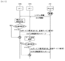
図7は、ネットワーク混雑状態でアクセス遮断動作を示す例示的な流れ図である。 FIG. 7 is an exemplary flowchart showing an access blocking operation in a network congestion state.
図7に示すように、ネットワークまたはeNodeB200の過負荷または混雑状態で、eNodeB200は、システム情報を介してACB(Access Class Barring)関連情報をブロードキャスティングすることができる。前記システム情報は、SIB(System Information Block)タイプ2である。
As illustrated in FIG. 7, the
前記SIB(System Information Block)タイプ2は、以下の表のようなACB関連情報を含むことができる。
The SIB (System Information Block)
一方、前記UE1 100aは、IMSサービス、例えば、VoLTEによる呼び(call)の発信を決定し、サービス要求メッセージを生成する。同様に、UE2 100bは、一般データの発信を決定し、サービス要求メッセージを生成する。
Meanwhile, the
次に、前記UE1 100aは、RRC接続要求メッセージを生成する。同様に、UE2 100bは、RRC接続要求メッセージを生成する。
Next, the
一方、前記UE1 100aは、アクセス遮断検査(即ち、ACB適用可否)を実行する。同様に、UE2 100bは、アクセス遮断検査(即ち、ACB適用可否)を実行する。
On the other hand, the
もし、前記ACBの適用対象がない場合、前記UE1 100aと前記UE2 100bは、各々、サービス要求(または、拡張サービス要求)メッセージとRRC接続要求メッセージを送信することができる。しかし、前記ACBの適用対象の場合、前記UE1 100aと前記UE2 100bは、両方ともRRC接続要求メッセージを送信することができない。
If there is no application target of the ACB, the
前記アクセス遮断検査に対して具体的に説明すると、下記の通りである。UEは、一般的に10個アクセスクラス(例えば、AC0、AC1、…、AC9)のうち少なくとも一つがランダムに割り当てられている。例外的に、緊急非常アクセスのためにはAC10が割り当てられる。このように、ランダムに割り当てられたアクセスクラスの値は、前記UE1 100及びUE2 100bの各USIMには格納されることができる。そのとき、前記UE1 100aと前記UE2 100bは、前記格納されたアクセスクラスに基づいて、前記受信したACB関連情報に含まれている遮断ファクタ(barring factor)フィールドを利用することで、アクセス遮断が適用されるかどうかを確認する。このようなアクセス遮断検査は、前記UE1 100aと前記UE2 100bの各AS(Access Stratum)階層、即ち、RRC階層で実行される。
The access blocking inspection will be described in detail as follows. Generally, at least one of 10 access classes (for example, AC0, AC1,..., AC9) is randomly assigned to the UE. Exceptionally, AC10 is assigned for emergency emergency access. In this way, randomly assigned access class values can be stored in the respective USIMs of the
前記アクセス遮断検査に対し、より具体的に説明すると、下記の通りである。 The access blocking inspection will be described in more detail as follows.
前記UE1 100a及びUE2 100bが各々受信したSIBタイプ2にac−BarringPerPLMN−Listが含まれており、前記ac−BarringPerPLMN−Listには上位階層に選択されたPLMNに対応するplmn−identityIndexとマッチングされるAC−BarringPerPLMNエントリが含まれている場合、前記上位階層により選択されたPLMNと対応するplmn−identityIndexとマッチングされるAC−BarringPerPLMNエントリを選択する。
The
次に、前記UE1 100a及びUE2 100bがRRC接続要求をしようとする場合、TbarringとしてT303を使用し、遮断パラメータとしてac−BarringForMO−Dataを使用し、アクセス遮断検査を実行する。
Next, when the
遮断されると決定される場合、前記UE1 100a及びUE2 100bの各AS(RRC)階層は、RRC接続確立の失敗を上位階層に知らせる。
When it is determined to be blocked, each AS (RRC) layer of the
次に、このように、アクセスが遮断される時、各AS(RRC)階層は、T302タイマまたはTbarringタイマが駆動中であるかどうかを判断する。もし、駆動中でない場合、前記T302タイマまたはTbarringタイマを駆動する。 Next, when access is blocked in this way, each AS (RRC) layer determines whether a T302 timer or a Tbarring timer is running. If not, the T302 timer or Tbarring timer is driven.
一方、前記T302タイマまたはTbarringタイマが駆動中には前記AS(RRC)階層は、該当セルに対する全てのアクセスが遮断されると見なす。 On the other hand, while the T302 timer or Tbarring timer is operating, the AS (RRC) layer considers that all accesses to the corresponding cell are blocked.
以上で説明した通り、ネットワーク過負荷及び混雑状況で、eNB/RNCがACB(Access Class Barring)関連情報をUEに提供する。そのとき、UEは、USIMに格納されている自分のアクセスクラス(access class)に基づいて、受信したACB情報に含まれている遮断ファクタ(Barring factor)を利用してアクセス遮断(Access Barring)をチェックするようになる。このようなアクセス遮断検査を介して最終的にアクセス試みをすることができなくする。即ち、アクセス遮断検査を介して該当セルに対するアクセスが遮断される場合、UEは、アクセスを試みることができず、該当セルに対するアクセスが遮断されない場合、UEは、アクセスを試みるようになる。このようなアクセス遮断検査は、UEのAS(Access Stratum)階層で実行する。ここで、アクセス試みは、UEのAS(RRC)階層でeNB/RNCへのRRC接続要求メッセージを送信することを意味する。 As described above, the eNB / RNC provides ACB (Access Class Barring) related information to the UE in a network overload and congestion situation. At this time, the UE performs access blocking using the blocking factor (Barring factor) included in the received ACB information based on its own access class stored in the USIM. Come to check. Finally, access attempts cannot be made through such an access blocking check. That is, when access to the corresponding cell is blocked through the access blocking check, the UE cannot attempt access, and when access to the corresponding cell is not blocked, the UE tries to access. Such an access block check is executed in the AS (Access Stratum) layer of the UE. Here, the access attempt means transmitting an RRC connection request message to the eNB / RNC in the AS (RRC) layer of the UE.
一方、アクセス遮断検査は、UEの一般的な発信(MO:Mobile Originating)サービス、例えば、通話発信(originating call)、データ発信(originating data)、IMS音声発信(originating IMS voice)、IMS映像発信(originating IMS video)に対して実行される。即ち、ACBは、全てのアプリケーションプログラムのアクセス(ただし、応急サービスまたはページングに対する応答は除外)に対して適用される。 On the other hand, the access blocking inspection is performed by a general calling (MO) service of the UE, for example, calling calling, data sending (originating data), IMS voice sending (originating IMS voice), IMS video sending ( Originating IMS video). That is, ACB is applied to access of all application programs (except for an emergency service or a response to paging).
図8は、ACBが適用される場合、全てのアプリケーションによるアクセスが全て遮断される例を示す。 FIG. 8 shows an example in which access by all applications is blocked when ACB is applied.
図8を参照して分かるように、ACBが適用されると決定される場合、UEの全てのアプリケーションによるアクセス(ただし、応急サービスまたはページングに対する応答は除外)は全て遮断される。 As can be seen with reference to FIG. 8, if it is determined that ACB is applied, all access by the application of the UE (except for the response to the emergency service or paging) is blocked.
このように、全てのアプリケーションによるアクセスが遮断されることによって、差別化されたサービスが不可能になる。このような問題は、結局、ネットワークリソース浪費及びユーザの経験を低下させる。 In this way, differentiated services become impossible by blocking access by all applications. Such problems ultimately reduce network resource waste and user experience.
したがって、ネットワーク過負荷及び混雑状況で特定アプリケーショングループ/カテゴリ(application group/category)別にMO(Mobile Originating)サービス(例えば、通話発信またはデータ発信)を差別化するための方案が必要である。しかし、従来技術ではこれを具現することができる方案がない。 Therefore, there is a need for a scheme for differentiating MO (Mobile Originating) services (for example, calling or data transmission) by specific application group / category in a network overload and congestion situation. However, the prior art has no way of realizing this.
<本明細書の開示> <Disclosure of the present specification>
本明細書の開示は、一般的な発信(MO:Mobile Originating)サービス、例えば、通話発信(originating call)、データ発信(originating data)、IMS音声発信(originating IMS voice)、IMS映像発信(originating IMS video)を差等化する方案を提供する。このような方案をアプリケーション別混雑制御データ通信(Application specific Congestion control for Data Communication:ACDC)という。 The disclosure of the present specification is based on a general calling (MO) service such as calling calling, data sending (originating data), IMS voice calling (IMS voice), and IMS video sending (originating IMS). A method for equalizing video) is provided. Such a scheme is referred to as application specific congestion control data communication (ACDC).
特定アプリケーションのサービスを差別化するために、本明細書の開示は、ネットワーク(MME/SGSN/S−GW/P−GW等)がUEにアプリケーション関連情報、即ち、アプリケーショングループ/カテゴリ/優先順位情報/IDを提供/お知らせすることを提案する。このようなアプリケーション関連情報、即ち、アプリケーショングループ/カテゴリ/優先順位情報/IDは、ネットワークがアタッチ手順/TAU手順/RAU手順を介してUEに知らせることができる。即ち、ネットワークは、ATTACH受諾メッセージ、TAU受諾メッセージ、RAU受諾メッセージ)を介して前記アプリケーション関連情報をUEに提供/お知らせすることができる。また、このようなアプリケーション関連情報、即ち、アプリケーショングループ/カテゴリ/優先順位情報/IDは、NAS設定管理オブジェクト(Management Object:MO)または新しいアプリケーション管理オブジェクト(MO)(例えば、アプリケーション別アクセス制御MO)に定義/設定されている。このような場合、OMA DMベースのNAS設定管理オブジェクト(MO)または新しいアプリケーション管理オブジェクト(MO)を介して、前記アプリケーション関連情報、即ち、アプリケーショングループ/カテゴリ/優先順位情報/IDがUEに提供されることができる。 In order to differentiate the services of a specific application, the present disclosure discloses that the network (MME / SGSN / S-GW / P-GW, etc.) provides application related information, ie, application group / category / priority information, to the UE. / Propose to provide / notify ID. Such application related information, i.e., application group / category / priority information / ID, can be notified to the UE through the attach procedure / TAU procedure / RAU procedure by the network. That is, the network can provide / notify the application related information to the UE via an ATTACH acceptance message, a TAU acceptance message, and a RAU acceptance message. Also, such application-related information, that is, application group / category / priority information / ID, is a NAS setting management object (Management Object: MO) or a new application management object (MO) (for example, access control by application MO). Is defined / set. In such a case, the application related information, ie, application group / category / priority information / ID, is provided to the UE via an OMA DM-based NAS configuration management object (MO) or a new application management object (MO). Can.
または、アプリケーション関連情報、即ち、アプリケーショングループ/カテゴリ/優先順位情報/IDは、UEにUSIM等に予め設定されている。 Alternatively, application-related information, that is, application group / category / priority information / ID, is set in advance in the USIM or the like in the UE.
このようなアプリケーション関連情報、即ち、アプリケーショングループ/カテゴリ/優先順位情報/IDは、その重要度(priority)によって昇順(ascending order)の値を有することができる。具体的に、アプリケーション関連情報、即ち、アプリケーショングループ/カテゴリ/優先順位情報/ID=1(または、A、binary及び/またはstring)の場合、highest/primary priorityを意味する。highest/primary priorityを有するアプリケーションのサービスの場合は、ACBを最も優先的に通過可能でなければならないことを意味する(即ち、遮断率が低い)。もし、アプリケーション関連情報、即ち、アプリケーショングループ/カテゴリ/優先順位情報/ID=2(または、B、その他のbinary及び/またはstring)の場合、次順位の優先順位を意味する。次順位の優先順位を有するアプリケーションのサービスの場合は、ACBを2番目の優先順位に通過可能でなければならないことを意味する。もし、アプリケーション関連情報、即ち、アプリケーショングループ/カテゴリ/優先順位情報/ID=n(または、Z、binary及び/またはstring)の場合、最下位の優先順位を意味する。最下位の優先順位を有するアプリケーションのサービスの場合は、ACBを最後の優先順位に通過可能でなければならないことを意味する(即ち、遮断率が高い)。 Such application-related information, i.e., application group / category / priority information / ID, may have an ascending order value according to its priority. Specifically, in the case of application related information, that is, application group / category / priority information / ID = 1 (or A, binary and / or string), it means highest / primary priority. In the case of a service of an application having a highest / primary priority, this means that the ACB must be able to pass through the ACB most preferentially (ie, the blocking rate is low). If application related information, that is, application group / category / priority information / ID = 2 (or B, other binary and / or string), it means the next priority. In the case of a service of an application having the next priority, this means that the ACB must be able to pass the second priority. If application related information, that is, application group / category / priority information / ID = n (or Z, binary and / or string), it means the lowest priority. In the case of the service of the application having the lowest priority, this means that the ACB must be able to pass to the last priority (ie, the blocking rate is high).
それに対し、このようなアプリケーション関連情報、即ち、アプリケーショングループ/カテゴリ/優先順位情報/IDは、その重要度(priority)によって降順(descending order)の値を有することができる。即ち、アプリケーショングループ/カテゴリ(group/category/priority)情報/ID=1(または、A、binary及び/またはstring)の場合、最下位の優先順位を意味する。このように、最下位の優先順位を有するアプリケーションのサービスの場合は、ACBを最後の優先順位に通過可能でなければならないことを意味する(即ち、遮断率が高い)。もし、アプリケーショングループ/カテゴリ/優先順位情報/ID=n(または、Z、binary及び/またはstring)の場合、highest/primary priorityを意味し、このようなアプリケーションのサービスの場合は、ACBを最も優先的に通過可能でなければならないことを意味する(即ち、遮断率が低い)。 On the other hand, such application-related information, that is, application group / category / priority information / ID may have a descending order value according to its priority. That is, in the case of application group / category (group / category / priority) information / ID = 1 (or A, binary and / or string), it means the lowest priority. Thus, in the case of the service of the application having the lowest priority, it means that the ACB must be able to pass to the last priority (that is, the blocking rate is high). If application group / category / priority information / ID = n (or Z, binary and / or string), it means highest / primary priority. In the case of such an application service, ACB has the highest priority. Means that it must be able to pass through (ie, the interception rate is low).
他方、ネットワーク(例えば、基地局)は、ACDC設定情報(即ち、アプリケーショングループ/カテゴリ/優先順位情報/ID別に、遮断比率(barring rates)、遮断ファクタ(barring factor)、遮断時間(mean barring time)、ローミング情報、ACBスキップ設定などの情報)をSIBを介してUEに提供することができる。ここで、ACBスキップ設定は、ACBスキップ=On/TrueまたはACBスキップ=Off/Falseで表現されることができる。ここで、前記ローミング情報は、UEがローミングした状況でアプリケーショングループ/カテゴリ/優先順位情報/ID別に遮断可否を差別化する機能(ACDC検査)を適用するかどうか(適用するかまたは適用しないか)に対する情報を意味する。 On the other hand, the network (e.g., base station) is connected to the ACDC configuration information (i.e., application group / category / priority information / ID, blocking rates, blocking factor, and blocking time). , Information on roaming information, ACB skip setting, etc.) can be provided to the UE via the SIB. Here, the ACB skip setting can be expressed as ACB skip = On / True or ACB skip = Off / False. Here, whether the roaming information applies a function (ACDC inspection) for differentiating whether or not to block by application group / category / priority information / ID in a situation where the UE roams (applies or does not apply) Means information for.
前記ネットワーク(eNB)からSIBにより提供されるACDC設定情報(例えば、アプリケーショングループ/カテゴリ/優先順位情報/ID別の遮断比率、遮断ファクタ、平均遮断時間、ローミング情報、ACBスキップ設定などの情報)は、周期的に提供/更新されることができる。 ACDC setting information provided by the SIB from the network (eNB) (for example, application group / category / priority information / ID-specific blocking ratio, blocking factor, average blocking time, roaming information, ACB skip setting information, etc.) Can be provided / updated periodically.
I.本明細書の提案1
本明細書の提案1によると、ネットワークから提供されるACDC設定情報(即ち、アプリケーショングループ/カテゴリ/優先順位情報/ID別に、遮断比率(barring rates)、遮断ファクタ(barring factor)、遮断時間(mean barring time)、ローミング情報、ACBスキップ設定などの情報)をUEのAS階層(RRC)が受信することができる。
According to
したがって、本明細書の提案1によると、UEのAS(RRC)階層は、アクセス遮断検査(即ち、ACDC検査)を実行することができる。このように、UEのAS(RRC)階層は、アクセス遮断検査を実行する時、ネットワーク(例えば、基地局)から提供された前記ACDC設定情報に基づいてアプリケーショングループ/カテゴリ/優先順位情報/ID別にACDC検査を実行する。ここで、前記ACDC検査を実行するとは、アプリケーションのサービスが開始される時、ACDC設定情報(即ち、アプリケーショングループ/カテゴリ/優先順位情報/ID別に提供された遮断比率、遮断ファクタ、平均遮断時間、ローミング情報などの情報)を利用し、前記アプリケーションのサービスアクセス試み(access attempt)を許容するかまたは許容しないかを決定するということを意味する。前記アプリケーションのサービスアクセス試み(access attempt)を許容する場合、そのままアプリケーションのサービスがアプリケーション階層で開始されてネットワークにサービスセッション連結が進行され、前記アプリケーションのサービス試みを許容しない場合、それ以上アプリケーションのサービスのネットワークにセッション連結が試みられない。
Thus, according to
また、UEのAS(RRC)階層でアクセス遮断検査を実行する時、ネットワーク(例えば、基地局)で提供されるACBスキップ設定情報に基づいてアプリケーショングループ/カテゴリ/優先順位情報/ID別にアクセス遮断検査をスキップ(即ち、ACDC検査のスキップ)することもできる。 Also, when performing an access block check at the AS (RRC) layer of the UE, an access block check is performed for each application group / category / priority information / ID based on the ACB skip setting information provided in the network (eg, base station). Can be skipped (i.e., skipping ACDC inspection).
もし、ネットワーク(例えば、基地局)から前記本提案のACDC設定情報(即ち、アプリケーショングループ/カテゴリ/優先順位情報/ID別に遮断比率、遮断ファクタ、平均遮断時間、ローミング情報などの情報)とACB情報が同時にSIBを介してUEに提供される場合、UEは、前記ACDC設定情報のみを適用してACDC検査のみを実行することができる。即ち、ACB情報を適用するACBは実行しない。 If the proposed ACDC setting information from the network (for example, a base station) (that is, information such as blocking ratio, blocking factor, average blocking time, roaming information for each application group / category / priority information / ID) and ACB information Are provided to the UE via the SIB at the same time, the UE can perform only the ACDC check by applying only the ACDC configuration information. That is, ACB to which ACB information is applied is not executed.
または、ネットワーク(MME/SGSN/基地局など)からインディケーション/設定によって本提案のACDC設定情報と一般的なACB情報の中から選択して適用できる。即ち、ACB検査を実行したり、ACDC検査を実行することができる。 Alternatively, the proposed ACDC setting information and general ACB information can be selected and applied from a network (MME / SGSN / base station, etc.) by indication / setting. That is, an ACB inspection or an ACDC inspection can be executed.
前記提案1は、UEのIDLEモード及びCONNECTEDモードの両方ともに適用できる。
The
または、前記提案1は、UEがIDLEモードであるかまたはCONNECTEDモード(例えば、EMM−IDLE/RRC−IDLEモードまたはEMM−CONNECTED/RRC−CONNECTEDモード)であるかによって、ACDC設定情報を異なるように適用してACDC検査を実行することができる。
Alternatively, the
以上で説明した前記提案1は、提案1a、提案1b、提案1cに区分される。これを図面を参照して詳細に説明する。
The
図9は、本明細書の提案1aを示す信号流れ図である。 FIG. 9 is a signal flow diagram illustrating Proposition 1a of the present specification.
図9を参照して説明すると、下記の通りである。 This will be described with reference to FIG.
(Step1)ネットワーク(例えば、基地局)は、ACDC設定情報(即ち、アプリケーショングループ/カテゴリ/優先順位情報/ID別に、ACDCの遮断比率(barring rates)、遮断ファクタ(barring factor)、遮断時間(mean barring time)、ローミング情報、ACBスキップ設定などの情報)をSIBを介してUEに提供することができる (Step 1) A network (for example, a base station) is connected to an ACDC setting information (ie, application group / category / priority information / ID, an ACDC blocking rate, a blocking factor, a blocking time (mean)). information such as barring time), roaming information, ACB skip setting, etc.) can be provided to the UE via the SIB
(Step2)一方、UEで特定アプリケーションが実行され、前記特定アプリケーションによりデータ通信サービスが要求されると、前記特定アプリケーションの実行を担当するアプリケーション階層は、前記アプリケーション関連情報、即ち、アプリケーションのグループ/カテゴリ/優先順位情報/IDをNAS階層に提供する。このとき、このようなアプリケーション関連情報は、事前にUEの予め設定/定義されていることがある。その代案として、このようなアプリケーション関連情報は、ネットワークから提供を受けてAS(RRC)階層がアプリケーション階層に提供されることもでき、アプリケーション階層がデータ通信サービスを開始する時、AS(RRC)階層に情報提供要求をして提供を受けることもできる。) (Step 2) On the other hand, when a specific application is executed in the UE and a data communication service is requested by the specific application, the application hierarchy responsible for the execution of the specific application is the application related information, that is, the application group / category / Provides priority information / ID to the NAS hierarchy. At this time, such application-related information may be set / defined in advance in the UE. Alternatively, such application-related information can be provided from the network and the AS (RRC) layer can be provided to the application layer. When the application layer starts a data communication service, the AS (RRC) layer is provided. It is also possible to receive information by requesting information. )
このようなアプリケーション関連情報と共に/または別途に、アプリケーションのサービスの開始と終了を知らせるStart/StopまたはSet/Resetのようなインディケーション情報がNASまたはRRC階層に提供されることができる。この場合、Start/Setを受けた時点からStop/Resetを受けた時点までACDC検査が実行されることができる。 In addition to / or separately from such application-related information, indication information such as Start / Stop or Set / Reset that informs the start and end of application services may be provided to the NAS or RRC layer. In this case, the ACDC inspection can be performed from the time of receiving Start / Set to the time of receiving Stop / Reset.
(step3)NAS階層は、アプリケーション階層から受けたアプリケーション関連情報、即ち、アプリケーショングループ/カテゴリ/優先順位情報/IDに基づいて、ACDCのためのアプリケーションカテゴリを決定する。例えば、アプリケーション階層から該当アプリケーションのIDの伝達を受けた場合、NAS階層は、前記該当アプリケーションのIDがACDCのどのアプリケーションカテゴリに該当するかを決定する。 (Step 3) The NAS hierarchy determines an application category for ACDC based on the application related information received from the application hierarchy, that is, application group / category / priority information / ID. For example, when the ID of the corresponding application is received from the application layer, the NAS layer determines to which application category of ACDC the ID of the corresponding application corresponds.
(step4)NAS階層は、アプリケーション階層から受けたアプリケーション関連情報またはアプリケーション関連情報+Start/StopまたはSet/Resetのようなインディケーション情報を、アプリケーションのサービスアクセスのためのサービス要求手順(SERVICE REQUESTメッセージの送信またはEXTENDED SERVICE REQUESTメッセージの送信)を開始する時、共にAS(RRC)階層に伝達する。もし、アプリケーション階層からStart/Setインディケーション情報を受けた場合、アプリケーションのサービスアクセスのためのサービス要求手順(SERVICE REQUESTメッセージの送信またはEXTENDED SERVICE REQUESTメッセージの送信)を開始する時、AS(RRC)階層にアプリケーション関連情報を伝達することができる。アプリケーション階層からStop/Resetインディケーション情報を受けた場合、アプリケーションのサービスアクセスのためのサービス要求手順(SERVICE REQUESTメッセージの送信またはEXTENDED SERVICE REQUESTメッセージの送信)またはTAU/RAU要求手順を開始する時、AS(RRC)階層にアプリケーション関連情報を伝達しない。 (Step 4) The NAS layer transmits application-related information received from the application layer or application-related information + indication information such as Start / Stop or Set / Reset, and a service request procedure (SERVICE REQUEST message transmission for service access of the application). Or, when EXTENDED SERVICE REQUEST message transmission is started, both are transmitted to the AS (RRC) layer. If Start / Set indication information is received from the application layer, the AS (RRC) layer is used to start a service request procedure (transmission of SERVICE REQUEST message or transmission of EXTENDED SERVICE REQUEST message) for application service access Application related information can be transmitted to. When receiving the Stop / Reset indication information from the application layer, when starting a service request procedure (sending a SERVICE REQUEST message or sending an EXTENDED SERVICE REQUEST message) or a TAU / RAU request procedure for application service access (RRC) Application related information is not transmitted to the hierarchy.
もし、アプリケーション階層から受けたアプリケーション関連情報またはアプリケーション関連情報+Start/StopまたはSet/Resetのようなインディケーション情報が複数個の場合またはNAS復旧(recovery)過程中にアプリケーション関連情報が変更された場合、 If there are a plurality of indication information such as application-related information or application-related information + Start / Stop or Set / Reset received from the application layer, or if the application-related information is changed during the NAS recovery (recovery) process,
i)最も高い(highest)アプリケーション関連情報のみをAS(RRC)階層に提供したり; i) providing only the highest application related information to the AS (RRC) hierarchy;
ii)最も低い(lowest)アプリケーション関連情報のみをAS(RRC)階層に提供したり;または、 ii) provide only the lowest application related information to the AS (RRC) hierarchy; or
iii)複数個のアプリケーション関連情報を全てAS(RRC)階層に提供することができる。 iii) All of the plurality of application related information can be provided to the AS (RRC) layer.
前記NAS復旧(recovery)は、RLF(radio link failure)または下位階層の失敗/エラーなどによってアプリケーションのサービスアクセスに対する再送信が発生した場合、AS階層(例えば、RRC階層)は、NAS階層に下位階層の失敗/エラーを知らせ、NAS階層は、NASシグナリング連結(再)設定のためのNAS復旧手順を実行する。NAS復旧のためにサービス要求手順またはTAU要求手順が実行されることができ、サービス要求手順は、アップリンクデータがある場合に実行されることができ、前記TAU要求手順は、アップリンクデータがない場合に実行されることができる。 The NAS recovery (recovery) is performed when the retransmission for the service access of the application occurs due to RLF (radio link failure) or failure / error of the lower layer, and the AS layer (for example, the RRC layer) is subordinate to the NAS layer. The NAS layer performs a NAS recovery procedure for NAS signaling connection (re) setting. A service request procedure or a TAU request procedure can be performed for NAS recovery, and the service request procedure can be performed when there is uplink data, and the TAU request procedure is free of uplink data. Can be executed in case.
前記i)、ii)、iii)方式は、NAS階層が認知決定するようになり、このとき、ネットワーク設定/政策、UE機能などにより、i)、ii)、iii)方式のうち一つが具現されて動作されることができる。 The i), ii), and iii) methods are recognized and determined by the NAS layer. At this time, one of the i), ii), and iii) methods is implemented according to the network setting / policy, UE function, and the like. Can be operated.
(step5)AS(RRC)階層は、前記NAS階層からアプリケーション関連情報またはアプリケーション関連情報+Start/StopまたはSet/Resetのようなインディケーション情報を受けた場合、NAS階層のアプリケーションのサービスアクセスのためのサービス要求手順(SERVICE REQUESTメッセージの送信またはEXTENDED SERVICE REQUESTメッセージの送信)またはTAU/RAU要求手順を開始する時、ネットワークから受信したACDC設定情報(即ち、アプリケーショングループ/カテゴリ/優先順位情報/ID別に提供された遮断比率、遮断ファクタ、平均遮断時間、ローミング情報などの情報)を利用し、前記アプリケーションのサービスアクセス(サービス要求手順またはTAU/RAU要求手順)試み(access attempt)を許容するかまたは許容しないかを決定する。 (Step 5) When the AS (RRC) layer receives application-related information or application-related information + indication information such as Start / Stop or Set / Reset from the NAS layer, the service for service access of the application in the NAS layer ACDC configuration information received from the network (ie, application group / category / priority information / ID provided) when initiating a request procedure (send SERVICE REQUEST message or send EXTENDED SERVICE REQUEST message) or TAU / RAU request procedure Service access (service) of the application using information such as the blocking rate, blocking factor, average blocking time, and roaming information. Determines no or acceptable to allow the determined procedure or TAU / RAU request procedure) attempts (access attempt).
もし、アプリケーション階層から受けたアプリケーション関連情報またはアプリケーション関連情報+Start/StopまたはSet/Resetのようなインディケーション情報が(同時に)複数個の場合またはNAS復旧過程中に変更された場合、 If the application related information received from the application hierarchy or application related information + indication information such as Start / Stop or Set / Reset is (simultaneously) plural or changed during the NAS recovery process,
i)最も高い(highest)アプリケーション関連情報に基づいてネットワークから受信したACDC設定情報(即ち、アプリケーショングループ/カテゴリ/優先順位情報/ID別に提供された遮断比率、遮断ファクタ、平均遮断時間、ローミング情報などの情報)を利用し、前記アプリケーションのサービスアクセス(サービス要求手順またはTAU/RAU要求手順)試み(access attempt)を許容するかまたは許容しないかを決定する; i) ACDC configuration information received from the network based on the highest application related information (ie, blocking ratio, blocking factor, average blocking time, roaming information provided by application group / category / priority information / ID, etc.) To determine whether the application's service access (service request procedure or TAU / RAU request procedure) access attempt is allowed or not allowed;
ii)最も低い(lowest)アプリケーション関連情報に基づいてネットワークから受信したACDC設定情報(即ち、アプリケーショングループ/カテゴリ/優先順位情報/ID別に提供された遮断比率、遮断ファクタ、平均遮断時間、ローミング情報などの情報)を利用し、前記アプリケーションのサービスアクセス(サービス要求手順またはTAU/RAU要求手順)試み(access attempt)を許容するかまたは許容しないかを決定する; ii) ACDC setting information received from the network based on the lowest application related information (ie, blocking ratio, blocking factor, average blocking time, roaming information provided by application group / category / priority information / ID, etc.) To determine whether the application's service access (service request procedure or TAU / RAU request procedure) access attempt is allowed or not allowed;
前記i)及びii)方式は、AS(RRC)階層が認知決定するようになり、このとき、ネットワーク設定/政策、UE機能などにより、i)及びii)方式のうち一つが具現されて動作されることができる。 The i) and ii) schemes are recognized and determined by the AS (RRC) layer, and at this time, one of the i) and ii) schemes is implemented and operated according to network settings / policies, UE functions, and the like. Can.
図10は、本明細書の提案1bを示す信号流れ図である。 FIG. 10 is a signal flow diagram showing Proposal 1b of this specification.
図10に示す提案1bは、図9に示す提案1aと異なる部分がいくつかある。以下、異なる部分を中心に説明する。 The proposal 1b shown in FIG. 10 has some parts different from the proposal 1a shown in FIG. The following description will focus on the different parts.
(step4)NAS階層は、前記サービス要求手順(SERVICE REQUESTメッセージの送信またはEXTENDED SERVICE REQUESTメッセージの送信)またはTAU/RAU要求手順を開始する時、(アプリケーショングループ/カテゴリ/優先順位情報/ID別に)新しいRRC確立原因値、新しい呼びタイプ(new call types)、またはサービスタイプ(service types)を定義してAS(RRC)階層に伝達できる。このとき、新しいRRC確立原因値、新しい呼びタイプ(call type)、またはサービスタイプは、互いに独立的に(一つのみ)使われたり、組合せで定義されて使われることができる。もし、アプリケーション階層からStart/Setインディケーション情報を受けた場合、アプリケーションのサービスアクセスのためのサービス要求手順(SERVICE REQUESTメッセージの送信またはEXTENDED SERVICE REQUESTメッセージの送信)またはTAU/RAU要求手順を開始する時、(アプリケーショングループ/カテゴリ/優先順位情報/ID別に)新しいRRC確立原因値、新しい呼びタイプ、またはサービスタイプを定義してAS(RRC)階層に伝達する。アプリケーション階層からStop/Resetインディケーション情報を受けた場合、以後にはアプリケーションのサービスアクセスのための従来の一般的なサービス要求手順(SERVICE REQUESTメッセージの送信またはEXTENDED SERVICE REQUESTメッセージの送信)またはTAU/RAU要求手順を実行する。即ち、新しいRRC確立原因値、新しい呼びタイプ、またはサービスタイプforアプリケーショングループ/カテゴリ/優先順位情報/IDを定義しない従来のサービス要求手順またはTAU/RAU要求手順を実行する。 (Step 4) When the NAS layer starts the service request procedure (transmission of SERVICE REQUEST message or transmission of EXTENDED SERVICE REQUEST message) or TAU / RAU request procedure (new by application group / category / priority information / ID) RRC establishment cause values, new call types, or service types can be defined and communicated to the AS (RRC) hierarchy. At this time, the new RRC establishment cause value, the new call type, or the service type may be used independently of each other (only one) or may be defined and used in combination. If Start / Set indication information is received from the application layer, a service request procedure for service access of the application (transmission of a SERVICE REQUEST message or transmission of an EXTENDED SERVICE REQUEST message) or a TAU / RAU request procedure is started. , Define new RRC establishment cause value, new call type, or service type (by application group / category / priority information / ID) and communicate to AS (RRC) layer. If Stop / Reset indication information is received from the application layer, a conventional general service request procedure (sending a SERVICE REQUEST message or sending an EXTENDED SERVICE REQUEST message) or a TAU / RAU is performed thereafter. Perform the requested procedure. That is, a conventional service request procedure or TAU / RAU request procedure that does not define a new RRC establishment cause value, a new call type, or a service type for application group / category / priority information / ID is executed.
もし、アプリケーション階層から受けたアプリケーション関連情報またはアプリケーション関連情報+Start/StopまたはSet/Resetのようなインディケーション情報が(同時に)複数個の場合またはNAS復旧過程中に変更された場合、 If the application related information received from the application hierarchy or application related information + indication information such as Start / Stop or Set / Reset is (simultaneously) plural or changed during the NAS recovery process,
i)最も高い(highest)アプリケーション関連情報に基づいてサービス要求手順(SERVICE REQUESTメッセージの送信またはEXTENDED SERVICE REQUESTメッセージの送信)またはTAU/RAU要求手順を開始する時、(アプリケーショングループ/カテゴリ/優先順位情報/ID別に)新しいRRC確立原因値、新しい呼びタイプ、またはサービスタイプを定義してAS(RRC)階層に伝達する。(このとき、新しいRRC確立原因値、新しい呼びタイプ、またはサービスタイプは、互いに独立的に(一つのみ)使われたり、組合せで定義されて使われることができる。);または、 i) When starting a service request procedure (send a SERVICE REQUEST message or send an EXTENDED SERVICE REQUEST message) or a TAU / RAU request procedure based on the highest application related information (application group / category / priority information) A new RRC establishment cause value, a new call type, or a service type is defined and communicated to the AS (RRC) layer. (At this time, a new RRC establishment cause value, a new call type, or a service type can be used independently of each other (only one) or defined in combination); or
ii)最も低い(lowest)アプリケーション関連情報に基づいてサービス要求手順(SERVICE REQUESTメッセージの送信またはEXTENDED SERVICE REQUESTメッセージの送信)またはTAU/RAU要求手順を開始する時、(アプリケーショングループ/カテゴリ/優先順位情報/ID別に)新しいRRC確立原因値、新しい呼びタイプ、またはサービスタイプを定義してAS(RRC)階層に伝達する。(このとき、新しいRRC確立原因値、新しい呼びタイプ、またはサービスタイプは、互いに独立的に(一つのみ)使われたり、組合せで定義されて使われることができる。);または、 ii) when starting a service request procedure (send SERVICE REQUEST message or send EXTENDED SERVICE REQUEST message) or TAU / RAU request procedure based on lowest application related information (application group / category / priority information) A new RRC establishment cause value, a new call type, or a service type is defined and communicated to the AS (RRC) layer. (At this time, a new RRC establishment cause value, a new call type, or a service type can be used independently of each other (only one) or defined in combination); or
前記i)及びii)方式は、NAS階層が認知決定するようになり、このとき、ネットワーク設定/政策、UE性能/機能などにより、i)及びii)方式のうち一つが具現されて動作されることができる。 The i) and ii) schemes are recognized and determined by the NAS layer. At this time, one of the i) and ii) schemes is implemented and operated according to network settings / policies, UE performance / functions, and the like. be able to.
(step5)AS(RRC)階層は、NAS階層からアプリケーション関連情報(即ち、アプリケーショングループ/カテゴリ/優先順位情報/ID)別にRRC確立原因値、新しい呼びタイプ、またはサービスタイプ(このとき、新しいRRC確立原因値、新しい呼びタイプ、またはサービスタイプは、互いに独立的に(一つのみ)使われたり、組合せで定義されて使われることができる)に基づいて、NAS階層のアプリケーションのサービスアクセスのためのサービス要求手順(SERVICE REQUESTメッセージの送信またはEXTENDED SERVICE REQUESTメッセージの送信)またはTAU/RAU要求手順を開始する時、(アプリケーショングループ/カテゴリ/優先順位情報/ID別に)、新しいRRC確立原因値、新しい呼びタイプ、またはサービスタイプを定義してサービス要求手順またはTAU/RAU要求手順を開始する時)、ネットワークから受信したACDC設定情報(即ち、アプリケーショングループ/カテゴリ/優先順位情報/ID別に提供された遮断比率、遮断ファクタ、平均遮断時間、ローミング情報などの情報)を利用し、前記アプリケーションのサービスアクセス(サービス要求手順またはTAU/RAU要求手順)試み(access attempt)を許容するかまたは許容しないかを決定する。 (Step 5) The AS (RRC) layer determines an RRC establishment cause value, a new call type, or a service type (at this time, a new RRC establishment) for each application related information (ie, application group / category / priority information / ID) from the NAS layer. Based on cause value, new call type, or service type can be used independently of each other (only one, or can be defined and used in combination) for service access of NAS hierarchy applications When starting a service request procedure (send SERVICE REQUEST message or send EXTENDED SERVICE REQUEST message) or TAU / RAU request procedure (by application group / category / priority information / ID) When defining a RC establishment cause value, a new call type, or a service type and initiating a service request procedure or TAU / RAU request procedure), ACDC configuration information received from the network (ie, application group / category / priority information / Whether to allow service access (service request procedure or TAU / RAU request procedure) access attempt of the application using the blocking ratio, blocking factor, average blocking time, roaming information, etc. provided for each ID Or decide not to allow.
ここで、AS(RRC)階層は、NAS階層からアプリケーショングループ/カテゴリ/優先順位情報/ID別にRRC確立原因値、新しい呼びタイプ、またはサービスタイプに基づいてアプリケーショングループ/カテゴリ/優先順位を認知することができる。したがって、ネットワークから受信したACDC設定情報(即ち、アプリケーショングループ/カテゴリ/優先順位情報/ID別に提供された遮断比率、遮断ファクタ、平均遮断時間、ローミング情報などの情報)を利用し、前記アプリケーションのサービスアクセス(サービス要求手順またはTAU/RAU要求手順)試み(access attempt)を許容するかまたは許容しないかを決定することができる。 Here, the AS (RRC) layer recognizes the application group / category / priority based on the RRC establishment cause value, new call type, or service type for each application group / category / priority information / ID from the NAS layer. Can do. Therefore, using the ACDC setting information received from the network (that is, information such as blocking ratio, blocking factor, average blocking time, roaming information provided for each application group / category / priority information / ID), the service of the application It can be determined whether access (service request procedure or TAU / RAU request procedure) access attempts are allowed or not allowed.
図11は、本明細書の提案1cを示す信号流れ図である。 FIG. 11 is a signal flow diagram illustrating Proposal 1c herein.
図11に示す提案1cは、提案1a及び提案1bと異なる部分がいくつかある。以下、異なる部分を中心に説明する。 The proposal 1c shown in FIG. 11 has some parts different from the proposal 1a and the proposal 1b. The following description will focus on the different parts.
(Step2)UEで特定アプリケーションが実行され、前記特定アプリケーションによりデータ通信サービスが要求されると、前記特定アプリケーションの実行を担当するアプリケーション階層は、前記アプリケーション関連情報(即ち、アプリケーションのグループ/カテゴリ/優先順位情報/ID)をAS階層に提供する。 (Step 2) When a specific application is executed in the UE and a data communication service is requested by the specific application, an application hierarchy responsible for execution of the specific application displays the application related information (ie, application group / category / priority). (Rank information / ID) is provided to the AS hierarchy.
(Step3)AS(RRC)階層は、アプリケーション階層から受けたアプリケーション関連情報に基づいて、ACDCのためのアプリケーションカテゴリを決定する。例えば、アプリケーション階層から該当アプリケーションのIDの伝達を受けた場合、NAS階層は、前記該当アプリケーションのIDがACDCのどのアプリケーションカテゴリに該当するを決定する。 (Step 3) The AS (RRC) layer determines an application category for ACDC based on the application related information received from the application layer. For example, when receiving the ID of the corresponding application from the application layer, the NAS layer determines which application category of the ACDC the ID of the corresponding application corresponds to.
(step5)AS(RRC)階層は、前記アプリケーション階層からアプリケーション関連情報またはアプリケーション関連情報+Start/StopまたはSet/Resetのようなインディケーション情報を受けた場合、NAS階層のアプリケーションのサービスアクセスのためのサービス要求手順(SERVICE REQUESTメッセージの送信またはEXTENDED SERVICE REQUESTメッセージの送信)またはTAU/RAU要求手順を開始する時、ネットワークから受信したACDC設定情報(即ち、アプリケーショングループ/カテゴリ/優先順位情報/ID別に提供された遮断比率、遮断ファクタ、平均遮断時間、ローミング情報などの情報)を利用し、前記アプリケーションのサービスアクセス(サービス要求手順またはTAU/RAU要求手順)試み(access attempt)を許容するかまたは許容しないかを決定する。 (Step 5) When the AS (RRC) layer receives application-related information or application-related information + indication information such as Start / Stop or Set / Reset from the application layer, the service for service access of the application in the NAS layer ACDC configuration information received from the network (ie, application group / category / priority information / ID provided) when initiating a request procedure (send SERVICE REQUEST message or send EXTENDED SERVICE REQUEST message) or TAU / RAU request procedure Access information of the application using information such as blocking ratio, blocking factor, average blocking time, roaming information, etc.) Service request procedure or TAU / RAU request procedure) to determine whether or not acceptable to allow attempts (access attempt).
II.本明細書の提案2(仮出願に記載された提案3)
II.
提案2(仮出願に記載された提案3)は、図9、図10及び図11の図示と類似する。したがって、別途の図面を参照せずに、図9、図10及び図11をそのまま参照して説明する。
Proposal 2 (
(step0)ネットワーク(事業者)は、アプリケーション関連情報(アプリケーションのグループ/カテゴリ/優先順位情報/ID)をUEに提供(または、設定)する。例えば、OMA DMを利用したアプリケーションMO(例えば、アプリケーション別(アクセス制御)MO)を介してアプリケーション関連情報(アプリケーショングループ/カテゴリ/優先順位情報/ID)がUEに提供されたり、USIMに(予め)設定されてUEに提供される。UEのNAS階層またはアプリケーション階層または運営体制(OS)を含むアプリケーション制御階層またはAS(RRC)階層は、AT−commandなどを介してこのようなアプリケーショングループ/カテゴリ/優先順位情報/IDを得ることができるようになる。 (Step 0) The network (operator) provides (or sets) application-related information (application group / category / priority information / ID) to the UE. For example, application related information (application group / category / priority information / ID) is provided to the UE via an application MO (for example, application-specific (access control) MO) using OMA DM, or (pre-) Configured and provided to the UE. The application control layer or AS (RRC) layer including the NAS layer or application layer or operating system (OS) of the UE may obtain such application group / category / priority information / ID through the AT-command or the like. become able to.
したがって、前記アプリケーション関連情報は、ネットワーク(事業者)からUEに予め提供されてUEのNAS階層またはアプリケーション階層または運営体制(OS)を含むアプリケーション制御階層)は認知することができる。このようなアプリケーション関連情報は、ネットワーク(事業者)から周期的にまたは特点時点などにUEに提供されることができる。 Therefore, the application-related information is provided in advance from the network (operator) to the UE, and can be recognized by the NAS layer, the application layer, or the operating system (OS) of the UE. Such application-related information can be provided to the UE periodically or at a special point in time from the network (operator).
(step1)ネットワーク(例えば、基地局)は、ACDC設定情報(即ち、アプリケーショングループ/カテゴリ/優先順位情報/ID別に遮断比率、遮断ファクタ、平均遮断時間、ACBスキップ設定などの情報)をSIBを介してUEに提供する。このようなACDC設定情報は、UEがEMM−IDLEまたはEMM−CONNECTEDモード(RRC−IDLEまたはRRC−CONNECTEDモードである時、全て提供されることができる。このようなACDC設定情報は、UEのAS(RRC)階層がネットワークから受信することができる。 (Step 1) The network (eg, base station) sends ACDC setting information (ie, information such as blocking ratio, blocking factor, average blocking time, and ACB skip setting for each application group / category / priority information / ID) via the SIB. To the UE. Such ACDC configuration information can all be provided when the UE is in EMM-IDLE or EMM-CONNECTED mode (RRC-IDLE or RRC-CONNECTED mode. Such ACDC configuration information is provided in the AS of the UE. The (RRC) hierarchy can be received from the network.
(step2)アプリケーション階層は、アプリケーションのサービス提供のためのサービスアクセス試みをする場合(即ち、発信(MO)データまたは発信(MO)シグナリング)、前記取得したアプリケーション関連情報(アプリケーショングループ/カテゴリ/優先順位情報/ID)とアプリケーションID/情報/インディケーションをNAS階層に提供する。また、(サービスアクセスセッション)セッティング/開始インディケーション/情報を共にNAS階層に提供することができる。 (Step 2) The application layer makes a service access attempt for providing the service of the application (that is, outgoing (MO) data or outgoing (MO) signaling), and the obtained application related information (application group / category / priority) Information / ID) and application ID / information / indication are provided to the NAS hierarchy. In addition, both (service access session) setting / start indication / information can be provided to the NAS hierarchy.
(step4)NAS階層は、アプリケーション階層からアプリケーションのサービス開始の要求を受けると、サービス要求手順(SERVICE REQUESTメッセージの送信またはEXTENDED SERVICE REQUESTメッセージの送信)またはTAU手順(TAU要求メッセージの送信)を実行するようになる。このとき、AS(RRC)階層にアプリケーション関連情報+アプリケーションID/情報/インディケーションを伝達するようになる。 (Step 4) Upon receiving a service start request for an application from the application layer, the NAS layer executes a service request procedure (transmission of a SERVICE REQUEST message or transmission of an EXTENDED SERVICE REQUEST message) or a TAU procedure (transmission of a TAU request message). It becomes like this. At this time, application related information + application ID / information / indication is transmitted to the AS (RRC) layer.
もし、アプリケーション階層から受けたアプリケーション関連情報+アプリケーションID/情報/インディケーションが複数個の場合またはNAS復旧過程中にアプリケーション変更された場合、 If there are a plurality of application related information + application ID / information / indication received from the application hierarchy, or the application is changed during the NAS recovery process,
i)最も高い(highest)アプリケーション関連情報+アプリケーションID/情報/インディケーションのみをAS(RRC)階層に提供したり; i) providing only the highest application related information + application ID / information / indication to the AS (RRC) hierarchy;
ii)最も低い(lowest)アプリケーション関連情報+アプリケーションID/情報/インディケーション)のみをAS(RRC)階層に提供したり;または、 ii) provide only the lowest application related information + application ID / information / indication) to the AS (RRC) hierarchy; or
iii)複数個のアプリケーション関連情報+アプリケーションID/情報/インディケーションを全てAS(RRC)階層に提供することができる。 iii) A plurality of application related information + application ID / information / indication can all be provided to the AS (RRC) layer.
前記i)、ii)及びiii)方式は、NAS階層が認知決定するようになり、このとき、ネットワーク設定/政策、UE機能(capability)などにより、i)、ii)及びiii)方式のうち一つが具現されて動作されることができる。 The i), ii), and iii) methods are recognized and determined by the NAS layer. At this time, one of the i), ii), and iii) methods depends on the network setting / policy, UE capability, etc. One can be embodied and operated.
もし、アプリケーション階層から追加的に(または、別途に)セッティング/開始インディケーション/情報を受けた時、現在(UEに)ACBが適用されている場合、NAS階層は、この遮断状態を無視し、アプリケーションのサービスアクセスのためのサービス要求手順(SERVICE REQUESTメッセージの送信またはEXTENDED SERVICE REQUESTメッセージの送信)またはTAU手順(TAU要求メッセージの送信)を開始/実行する。このようなサービス要求手順またはTAU手順を開始する時、AS(RRC)階層にアプリケーション関連情報+ACBスキップインディケーション(例えば、ACB skip−ON、SETまたはTRUE forg roup/category/priority“X”)を伝達するようになる。 If additional (or separately) setting / start indication / information is received from the application layer and the current ACB is applied (to the UE), the NAS layer will ignore this blocking state, Initiate / execute a service request procedure (send SERVICE REQUEST message or send EXTENDED SERVICE REQUEST message) or TAU procedure (send TAU request message) for application service access. When starting such a service request procedure or TAU procedure, application related information + ACB skip indication (for example, ACB skip-ON, SET or TRUE for loop group / category / priority “X”) is transmitted to the AS (RRC) layer. Will come to do.
または、NAS階層は、アプリケーション階層からアプリケーションのサービス開始の要求を受けると、そのためのサービス要求手順(SERVICE REQUESTメッセージの送信またはEXTENDED SERVICE REQUESTメッセージの送信)またはTAU手順(TAU要求メッセージの送信)を実行するようになる。このとき、サービス要求手順またはTAU手順を開始する時、(アプリケーショングループ/カテゴリ/優先順位情報/ID別に)新しいRRC確立原因値、新しい呼びタイプ、またはサービスタイプを定義してAS(RRC)階層に伝達する。このとき、新しいRRC確立原因値、新しい呼びタイプ、またはサービスタイプは、互いに独立的に(一つのみ)使われたり、組合せで定義されて使われることができる。) Alternatively, when the NAS layer receives an application service start request from the application layer, the NAS layer executes a service request procedure (transmission of a SERVICE REQUEST message or transmission of an EXTENDED SERVICE REQUEST message) or a TAU procedure (transmission of a TAU request message). Will come to do. At this time, when a service request procedure or TAU procedure is started, a new RRC establishment cause value, a new call type, or a service type is defined (by application group / category / priority information / ID) and is entered in the AS (RRC) hierarchy. introduce. At this time, the new RRC establishment cause value, the new call type, or the service type may be used independently of each other (only one) or may be defined and used in combination. )
もし、アプリケーション階層から受けたアプリケーション関連情報+アプリケーションID/情報/インディケーション情報が(同時に)複数個の場合またはNAS復旧過程中に変更された場合、 If the application related information received from the application hierarchy + application ID / information / indication information is plural (simultaneously) or changed during the NAS recovery process,
i)最も高い(highest)アプリケーション関連情報に基づいてサービス要求手順(SERVICE REQUESTメッセージの送信またはEXTENDED SERVICE REQUESTメッセージの送信)またはTAU/RAU要求手順を開始する時、(アプリケーショングループ/カテゴリ/優先順位情報/ID別に)新しいRRC確立原因値、新しい呼びタイプ、またはサービスタイプを定義してAS(RRC)階層に伝達する。(このとき、新しいRRC確立原因値、新しい呼びタイプ、またはサービスタイプは、互いに独立的に(一つのみ)使われたり、組合せで定義されて使われることができる。); i) When starting a service request procedure (send a SERVICE REQUEST message or send an EXTENDED SERVICE REQUEST message) or a TAU / RAU request procedure based on the highest application related information (application group / category / priority information) A new RRC establishment cause value, a new call type, or a service type is defined and communicated to the AS (RRC) layer. (At this time, a new RRC establishment cause value, a new call type, or a service type can be used independently (only one) or defined in combination).
ii)最も低い(lowest)アプリケーション関連情報に基づいてサービス要求手順(SERVICE REQUESTメッセージの送信またはEXTENDED SERVICE REQUESTメッセージの送信)またはTAU/RAU要求手順を開始する時、(アプリケーショングループ/カテゴリ/優先順位情報/ID別に)新しいRRC確立原因値、新しい呼びタイプ、またはサービスタイプを定義してAS(RRC)階層に伝達する。(このとき、新しいRRC確立原因値、新しい呼びタイプ、またはサービスタイプは、互いに独立的に(一つのみ)使われたり、組合せで定義されて使われることができる。);または、 ii) when starting a service request procedure (send SERVICE REQUEST message or send EXTENDED SERVICE REQUEST message) or TAU / RAU request procedure based on lowest application related information (application group / category / priority information) A new RRC establishment cause value, a new call type, or a service type is defined and communicated to the AS (RRC) layer. (At this time, a new RRC establishment cause value, a new call type, or a service type can be used independently of each other (only one) or defined in combination); or
前記i)及びii)方式は、NAS階層が認知決定するようになり、このとき、ネットワーク設定/政策、UE性能/機能などにより、i)及びii)方式のうち一つが具現されて動作されることができる。 The i) and ii) schemes are recognized and determined by the NAS layer. At this time, one of the i) and ii) schemes is implemented and operated according to network settings / policies, UE performance / functions, and the like. be able to.
もし、アプリケーション階層から追加的に(または、別途に)セッティング/開始インディケーション/情報を受けた時、現在(UEが)ACBが適用されている場合、NAS階層は、この遮断状態を無視し、アプリケーションのサービスアクセスのためのサービス要求手順またはTAU手順を開始/実行する。このようなサービス要求手順またはTAU手順を開始する時、(アプリケーショングループ/カテゴリ/優先順位情報/ID別に)新しいRRC確立原因値、新しい呼びタイプ、またはサービスタイプを定義してAS(RRC)階層に伝達する。アプリケーション階層からACBスキップStop/Resetインディケーション情報を受けた場合、以後にはアプリケーションのサービスアクセスのための従来の一般的なサービス要求手順またはTAU/RAU要求手順を実行する。即ち、新しいRRC確立原因値、新しい呼びタイプ、またはサービスタイプforアプリケーショングループ/カテゴリ/優先順位情報/IDを定義しない従来のサービス要求手順またはTAU/RAU要求手順を実行する。 If additional (or separately) setting / start indication / information is received from the application layer and the current (UE) ACB is applied, the NAS layer will ignore this blocking state, Initiate / execute a service request procedure or TAU procedure for application service access. When initiating such a service request procedure or TAU procedure, define a new RRC establishment cause value, new call type, or service type (by application group / category / priority information / ID) to the AS (RRC) hierarchy. introduce. When the ACB skip Stop / Reset indication information is received from the application layer, a conventional general service request procedure or TAU / RAU request procedure for service access of the application is subsequently executed. That is, a conventional service request procedure or TAU / RAU request procedure that does not define a new RRC establishment cause value, a new call type, or a service type for application group / category / priority information / ID is executed.
(step5)AS(RRC)階層は、NAS階層のアプリケーションのサービスアクセスのためのサービス要求手順またはTAU手順を開始する時、もし、NAS階層からアプリケーション関連情報+アプリケーションID/情報/インディケーションの提供を受けた場合、ネットワーク(例えば、基地局)から提供を受けたACDC設定情報(即ち、アプリケーショングループ/カテゴリ/優先順位情報/ID別に遮断比率、遮断ファクタ、平均遮断時間、ACBスキップ設定などの情報)に基づいてアプリケーショングループ/カテゴリ/優先順位情報/ID別にACDC検査を実行するようになる。 (Step 5) When the AS (RRC) layer starts a service request procedure or a TAU procedure for service access of an application in the NAS layer, it provides application related information + application ID / information / indication from the NAS layer. If received, the ACDC setting information received from the network (for example, base station) (ie, information such as blocking ratio, blocking factor, average blocking time, ACB skip setting by application group / category / priority information / ID) Based on the above, the ACDC inspection is executed for each application group / category / priority information / ID.
もし、アプリケーショングループ/カテゴリ/優先順位情報/ID別にACDCを通過するようになると、アプリケーションのサービスアクセスのためのRRC接続要求手順を実行するようになる。しかし、アプリケーショングループ/カテゴリ/優先順位情報/ID別にACDCを通過することができない場合(barringされる場合)、アプリケーションのサービスアクセスのためのRRC接続要求手順を実行しない。 If the application group / category / priority information / ID passes through the ACDC, an RRC connection request procedure for service access of the application is executed. However, when ACDC cannot be passed by application group / category / priority information / ID (when barring), the RRC connection request procedure for service access of the application is not executed.
もし、NAS階層から受けたアプリケーション関連情報+アプリケーションID/情報/インディケーションが(同時に)複数個の場合またはNAS復旧過程中に変更された場合、前述したように、i)最も高い(highest)ものを利用したり、ii)最も低い(lowest)ものを利用し、前記アプリケーションのサービスアクセス(サービス要求手順またはTAU/RAU要求手順)試み(access attempt)を許容するかまたは許容しないかを決定する; If the application related information + application ID / information / indication received from the NAS hierarchy is plural (simultaneously) or changed during the NAS recovery process, as described above, i) the highest one Or ii) use the lowest one to determine whether service access (service request procedure or TAU / RAU request procedure) access attempt of the application is allowed or not allowed;
もし、NAS階層のアプリケーションのサービスアクセスのためのサービス要求手順またはTAU手順を開始する時、(アプリケーショングループ/カテゴリ/優先順位情報/ID別に)新しいRRC確立原因値、新しい呼びタイプ、またはサービスタイプが定義されてNAS階層から共に提供されると、ネットワーク(例えば、基地局)から提供を受けたACDC設定情報(即ち、アプリケーショングループ/カテゴリ/優先順位情報/ID別に遮断比率、遮断ファクタ、平均遮断時間、ACBスキップ設定などの情報)に基づいてアプリケーショングループ/カテゴリ/優先順位情報/ID別にACDCを実行するようになる。 If a service request procedure or TAU procedure for NAS layer application service access is initiated, a new RRC establishment cause value, new call type, or service type (by application group / category / priority information / ID) When defined and provided together from the NAS hierarchy, ACDC setting information (ie, application group / category / priority information / ID by application group / category / priority information / ID) received from the network (eg, base station) , ACDC is executed for each application group / category / priority information / ID based on information such as ACB skip setting).
もし、アプリケーショングループ/カテゴリ/優先順位情報/ID別にACDCを通過するようになると、アプリケーションのサービスアクセスのためのRRC接続要求手順を実行するようになる。しかし、アプリケーショングループ/カテゴリ/優先順位情報/ID別にACDCを通過することができない場合(barringされる場合)、アプリケーションのサービスアクセスのためのRRC接続要求手順を実行しない。 If the application group / category / priority information / ID passes through the ACDC, an RRC connection request procedure for service access of the application is executed. However, when ACDC cannot be passed by application group / category / priority information / ID (when barring), the RRC connection request procedure for service access of the application is not executed.
もし、NAS階層から追加的に(または、別途に)ACBスキップインディケーション情報を受けた場合(ACBスキップインディケーション情報がACB skip−ON、SETまたはTRUE for group/category/priority“X”の場合)、現在ACB状態と関係なしでACBをスキップして前記アプリケーションのサービスアクセス(サービス要求手順またはTAU手順)試み(access attempt)を許容する。(即ち、現在遮断状態であるとしても、これを無視してサービス要求手順またはTAU手順を開始/実行してRRC接続確立を実行する。) If the ACB skip indication information is additionally (or separately) received from the NAS layer (when the ACB skip indication information is ACB skip-ON, SET or TRUE for group / category / priority “X”) The ACB is skipped regardless of the current ACB state, allowing service access (service request procedure or TAU procedure) access attempt of the application. (In other words, even if it is currently in the cut-off state, this is ignored and the service request procedure or the TAU procedure is started / executed to establish RRC connection.)
本明細書では、ネットワーク(eNB)からアプリケーショングループ/カテゴリ/優先順位/ID別のACBスキップ情報状態の変化/変動(例えば、from ACB skipping set/true to ACB skipping reset/false(from ACB skipping to No ACB skipping)またはfrom ACB skipping reset/false to ACB skipping set/true(from No ACB skipping to ACB skipping))が発生すると(発生を検知すると)、そのとき、AS(RRC)階層は、アプリケーション階層またはNAS階層(または、アプリケーション階層及びNAS階層)にACBスキップ設定情報変化/変動を知らせることができる。 In this specification, change / fluctuation of ACB skip information state by application group / category / priority / ID from network (eNB) (for example, from ACB skipping set / true to ACB skipping reset / false (from ACB skipping to No ACB skipping) or from ACB skipping reset / false to ACB skipping set / true (from No ACB skipping to ACB skipping) (when the generation is detected), then R ACB skip setting information in the hierarchy (or application hierarchy and NAS hierarchy) Information change / fluctuation can be notified.
以後、アプリケーション階層は、アプリケーショングループ/カテゴリ/優先順位情報/ID別のACBスキップ情報状態の変化/変動によってstep1〜step3を実行する。
Thereafter, the application hierarchy executes
もし、ネットワーク(例えば、基地局)からACDC設定情報(即ち、前記アプリケーショングループ/カテゴリ/優先順位情報/ID別に遮断比率、遮断ファクタ、平均遮断時間、ローミング情報、ACBスキップ設定などの情報)と一般的なACB情報が同時にSIBを介してUEに提供される場合、UEは、前記本提案のACDC設定情報(即ち、アプリケーショングループ/カテゴリ/優先順位情報/ID別に遮断比率、遮断ファクタ、平均遮断時間、ローミング情報、ACBスキップ設定などの情報)のみを適用して、ACB検査は、スキップを実行することができる(ACDC検査のみを実行) If the network (for example, base station) ACDC setting information (that is, information such as blocking ratio, blocking factor, average blocking time, roaming information, ACB skip setting by application group / category / priority information / ID) and general If the common ACB information is simultaneously provided to the UE via the SIB, the UE may configure the proposed ACDC configuration information (ie, blocking ratio, blocking factor, average blocking time by application group / category / priority information / ID). , Roaming information, ACB skip settings, etc.) only, and ACB inspection can be skipped (only ACDC inspection is performed)
または、ネットワーク(MME/SGSN/基地局など)からインディケーション/設定によって、本提案のACDC設定情報(即ち、アプリケーショングループ/カテゴリ/優先順位情報/ID別に遮断比率、遮断ファクタ、平均遮断時間、ローミング情報、ACBスキップ設定などの情報)と一般的なACB情報の中から選択して適用することでACB検査スキップを実行することもできる。 Alternatively, according to indication / setting from the network (MME / SGSN / base station, etc.), the proposed ACDC setting information (ie, blocking ratio, blocking factor, average blocking time, roaming by application group / category / priority information / ID) Information, information such as ACB skip setting) and general ACB information can be selected and applied to perform ACB inspection skip.
または、もし、ネットワーク(例えば、基地局)から前記ACDC設定情報と(従来の)一般的なACB情報が同時にSIBを介してUEに提供される場合、UEは、前記ACDC設定情報のみを適用してACDC検査をアプリケーション階層で先に実行し、前記ACDC検査を通過すると、AS(RRC)階層で再び従来の一般的なACB情報を適用するACBを実行することもできる。(即ち、ACDC検査とACB検査を重複実行する。) Or, if the ACDC configuration information and (conventional) general ACB information are simultaneously provided to the UE via SIB from the network (eg, base station), the UE applies only the ACDC configuration information. If the ACDC check is first executed in the application layer and the ACDC check is passed, the ACB that applies the conventional general ACB information can be executed again in the AS (RRC) layer. (In other words, ACDC inspection and ACB inspection are executed in duplicate.)
以上で説明した内容は、IMSベースのアプリケーションのサービスである場合にも適用されることができる。即ち、IMSベースのアプリケーションのサービスである場合も一般的なアプリケーショングループ/カテゴリのうち一つであることを意味する。) The contents described above can also be applied to a case of an IMS-based application service. That is, the IMS-based application service also means one of general application groups / categories. )
前記本提案は、UEのIDLEモードまたはCONNECTEDモードを全て適用することができる。例えば、EMM−IDLE/RRC−IDLEモードまたはEMM−CONNECTED/RRC−CONNECTEDモードにも適用されることができる。 The proposal can apply all of the IDLE mode or the CONNECTED mode of the UE. For example, the present invention can be applied to an EMM-IDLE / RRC-IDLE mode or an EMM-CONNECTED / RRC-CONNECTED mode.
または、前記本提案は、UEがIDLEモードであるかまたはCONNECTEDモード(例えば、EMM−IDLE/RRC−IDLEモードまたはEMM−CONNECTED/RRC−CONNECTEDモード)であるかによって、ACDC設定情報を各々異なるように適用してACDC検査を実行することもできる。 Alternatively, in the present proposal, the ACDC configuration information may be different depending on whether the UE is in IDLE mode or CONNECTED mode (for example, EMM-IDLE / RRC-IDLE mode or EMM-CONNECTED / RRC-CONNECTED mode). It can also be applied to perform ACDC inspection.
前記本提案のstep0)は、本明細書の提案1案、2案、4案、5a案、5b案、5c案、5d案を相互組合せて適用できる。前記本提案のstep1〜3)は、本明細書の提案1案、2案、4案、5a案、5b案、5c案、5d案を相互組合せて適用できる。
Step 0) of the present proposal can be applied by combining
一方、提案1a及び提案2を3GPP標準TS 24.301文書のD.1節の表現に合わせて説明すると、下記の通りである。
On the other hand, Proposal 1a and
もし、UEがACDCに対して設定されている場合、NAS階層は、要求に対してどのACDCカテゴリを適用すべきかを上位階層から伝達を受けたアプリケーションIDに基づいて決定する。EMM副階層は、一つのACDCカテゴリが適用される場合、アクセス制御の目的として下位階層に前記ACDCカテゴリを知らせることもでき、複数のACDCカテゴリが適用される場合、アクセス制御の目的として下位階層に最も高い等級のACDCカテゴリを知らせることができる。ただし、下記の場合は除外される。 If the UE is configured for ACDC, the NAS layer determines which ACDC category to apply to the request based on the application ID received from the upper layer. When one ACDC category is applied, the EMM sub-hierarchy can also inform the ACDC category to a lower layer as an access control purpose. When a plurality of ACDC categories are applied, the EMM sub-layer may be provided as a lower layer as an access control purpose. The highest grade ACDC category can be reported. However, the following cases are excluded.
−選択されたPLMNで前記UEがAC11乃至AC15を使用する場合 -When the UE uses AC11 to AC15 in the selected PLMN
−前記要求がページングに応答するための場合 -If the request is to respond to paging
一方、提案1a及び提案2を3GPP標準TS 36.331文書の6.3節の表現に合わせて説明すると、下記の通りである。
On the other hand, Proposal 1a and
基地局は、全てのUEに共通する無線リソース設定情報を含むSIBタイプ2を送信する。前記SIBタイプ2は、下記のような情報を含むことができる。
The base station transmits
以上の表の各フィールドを説明すると、下記の通りである。 Each field in the above table is described as follows.
一方、UEは、上位階層の要求によってRRC接続手順を実行する。この手順を実行する時、UEは、 On the other hand, the UE executes the RRC connection procedure according to the request of the upper layer. When performing this procedure, the UE
1>上位階層は、RRC接続要求がACDC検査の対象と指示しながら、ACDCカテゴリを提供し、併せて、UEは、発信通話のためのRRC接続を確立しようとする場合、 1> The upper layer provides an ACDC category, indicating that the RRC connection request is subject to ACDC inspection, and in addition, if the UE attempts to establish an RRC connection for outgoing calls,
2>TbarringとしてTxxxを利用し、ACDC barring parameterとしてacdc−BarringForMO−Dataを利用することによって、ACDCカテゴリ別にACDC遮断検査を実行する。 2> TDC is used as Tbarring, and acdc-BarringForMO-Data is used as ACDC barring parameter, thereby performing ACDC blockage inspection for each ACDC category.
2>アクセスが遮断される場合、 2> If access is blocked,
3>上位階層に前記RRC接続確立の失敗を知らせ、発信通話に対するACDCが適用されたことを知らせる。 3> Inform the upper layer of the failure to establish the RRC connection and inform that the ACDC for the outgoing call has been applied.
1>一方、上位階層は、RRC接続要求がACDC検査の対象と指示しながら、ACDCカテゴリを提供し、併せて、UEは、発信シグナリングのためのRRC接続を確立しようとする場合、 1> On the other hand, the upper layer provides the ACDC category while the RRC connection request indicates the object of ACDC inspection, and in addition, when the UE tries to establish the RRC connection for outgoing signaling,
2>TbarringとしてTyyyを利用し、ACDC barring parameterとしてacdc−BarringForMO−Signallingを利用することによって、ACDCカテゴリ別にACDC遮断検査を実行する。 2> Use Tyyy as Tbarring, and use acdc-BarringForMO-Signaling as ACDC barring parameter to execute ACDC blockage check for each ACDC category.
2>アクセスが遮断される場合、 2> If access is blocked,
3>上位階層に前記RRC接続確立の失敗を知らせ、発信シグナリングに対してACDCが適用されたことを知らせる。 3> Inform the upper layer of the failure to establish the RRC connection and inform that the ACDC has been applied to the outgoing signaling.
一方、UEは、前記ACDC遮断検査を下記のように実行する。 On the other hand, the UE performs the ACDC blocking check as follows.
1>タイマT3xxまたはTbarringが駆動中の場合 1> When timer T3xx or Tbarring is operating
2>該当セルへのアクセスは遮断されると見なす。 2> It is assumed that access to the cell is blocked.
1>しかし、SIBタイプ2がACDC遮断パラメータを含む場合
1> But when
2>UEがUSIMに一つ以上のアクセスクラス(11〜15)を格納している場合、 2> If the UE stores one or more access classes (11-15) in the USIM,
2>有効なアクセスクラスのうち少なくとも一つに対し、ACDC barring parameter内に含まれているacdc−BarringForSpecialACの対応ビットを0に設定する。 2> The corresponding bit of acdc-BarringForSpecialAC included in the ACDC barring parameter is set to 0 for at least one of the valid access classes.
3>該当セルに対するアクセスは遮断されないと見なす。 3> It is assumed that access to the cell is not blocked.
2>それ以外の場合、 2> Otherwise,
3>範囲0≦rand<1を満たすように均等に分散されたランダム値randを生成する。
3> Generate random values rand that are evenly distributed so as to satisfy the
3>前記randがACDC barring parameter内に含まれているacdc−BarringFactorにより指示される値より小さい場合 3> When the rand is smaller than the value indicated by acdc-BarringFactor included in the ACDC barring parameter
4>該当セルへのアクセスは遮断されないと見なす。 4> It is assumed that access to the cell is not blocked.
3>それ以外の場合 3> Otherwise
4>該当セルへのアクセスは遮断されると見なす。 4> It is assumed that access to the cell is blocked.
1>それ以外の場合 1> Otherwise
2>該当セルへのアクセスは遮断されると見なす; 2> Assume that access to the cell is blocked;
1>該当セルへのアクセスが遮断され、タイマTxxx及びTbarringが駆動中でない場合 1> When access to the cell is blocked and the timers Txxx and Tbarring are not being driven
2>範囲0≦rand<1を満たすように均等に分散されたランダム値randを生成する。
2> Generate random values rand that are evenly distributed so as to satisfy the
2>ACDC barring parameter内のacdc−BarringTimeを利用して下記のように算出されたタイマ値に設定されたタイマTbarringを駆動する。 2> The timer Tbarring set to the timer value calculated as follows is driven using the acdc-BarringTime in the ACDC barring parameter.
“Tbarring”=(0.7+0.6*rand)*acdc−BarringTime。 “Tbarring” = (0.7 + 0.6 * rand) * acdc-BarringTime.
一方、提案1b及び提案2を3GPP標準TS 24.301文書のD.1節の表現に合わせて説明すると、下記の通りである。
On the other hand, Proposal 1b and
EMM副階層がNASシグナリング連結の確立を要求する場合、UEにより使われるRRC確立原因は、NAS手順によって選択される。前記EMM副階層は、下位階層にアクセス制御の目的としてRRC接続確立原因と関連した呼びタイプを知らせる。もし、UEがEAB(ExtendedAccessBarring)に対して設定されている場合、EMM副階層は、アクセス制御の目的として下位階層に次のEABがこの要求に対して適用されると知らせる。ただし、下記の場合は除外されることができる。 When the EMM sub-layer requests establishment of NAS signaling connection, the RRC establishment cause used by the UE is selected by the NAS procedure. The EMM sub-layer informs the lower layer of the call type associated with the cause of RRC connection establishment for the purpose of access control. If the UE is configured for EAB (Extended Access Barring), the EMM sub-layer informs the lower layer that the next EAB will be applied to this request for access control purposes. However, the following cases can be excluded.
−選択されたPLMNで前記UEがAC11乃至AC15を使用する場合 -When the UE uses AC11 to AC15 in the selected PLMN
−前記要求がページングに応答するための場合 -If the request is to respond to paging
−RRC確立原因が“応急電話”に設定された場合 -When RRC establishment cause is set to "Emergency call"
−UEがNASシグナリング低順位(low priority)を無視(override)するように設定された場合、そしてEABを無視するように設定された場合、 -If the UE is configured to ignore NAS signaling low priority and if it is configured to ignore EAB,
−UEがNASシグナリング低順位(low priority)を無視(override)するように設定された場合、そしてEABを無視するように設定された場合、そしてUEが既にEABを無視して確立されたPDN接続を有している場合 -PDN connection established if the UE is configured to ignore NAS signaling low priority and if it is configured to ignore EAB, and the UE has already been established ignoring EAB If you have
一方、提案1b及び提案2を3GPP標準文書TS 36.331の6.3節の表現に合わせて説明すると、下記の通りである。
On the other hand, Proposal 1b and
基地局は、全てのUEに共通する無線リソース設定情報を含むSIBタイプ2を送信する。前記SIBタイプ2は、下記のような情報を含むことができる。
The base station transmits
以上の表の各フィールドを説明すると、下記の通りである。 Each field in the above table is described as follows.
一方、UEは、上位階層の要求によってRRC接続手順を実行する。この手順を実行する時、UEは、 On the other hand, the UE executes the RRC connection procedure according to the request of the upper layer. When performing this procedure, the UE
1>上位階層は、RRC接続要求がACDC検査の対象と指示しながら、ACDCカテゴリを提供し、併せて、UEは、ACDCカテゴリI(カテゴリII、III、…)に対する発信のためのRRC接続を確立しようとする場合、 1> The upper layer provides the ACDC category while indicating that the RRC connection request is subject to ACDC inspection. In addition, the UE makes an RRC connection for outgoing calls to ACDC category I (categories II, III,...). If you try to establish
2>TbarringとしてTxxxを利用し、ACDC barring parameterとしてacdc−BarringForMO−Dataを利用することによって、ACDCカテゴリ別にACDC遮断検査を実行する。 2> TDC is used as Tbarring, and acdc-BarringForMO-Data is used as ACDC barring parameter, thereby performing ACDC blockage inspection for each ACDC category.
2>アクセスが遮断される場合、 2> If access is blocked,
3>上位階層に前記RRC接続確立の失敗を知らせ、発信通話に対するACDCが適用されたことを知らせる。 3> Inform the upper layer of the failure to establish the RRC connection and inform that the ACDC for the outgoing call has been applied.
1>一方、上位階層は、RRC接続要求がACDC検査の対象と指示しながら、ACDCカテゴリを提供し、併せて、UEは、ACDCカテゴリI(カテゴリII、III、…)に対する発信のためのRRC接続を確立しようとする場合、 1> On the other hand, the upper layer provides the ACDC category while the RRC connection request indicates the object of ACDC inspection, and the UE also provides RRC for outgoing calls to ACDC category I (category II, III,...). When trying to establish a connection,
2>TbarringとしてTyyyを利用し、ACDC barring parameterとしてacdc−BarringForMO−Signallingを利用することによって、ACDCカテゴリ別にACDC遮断検査を実行する。 2> Use Tyyy as Tbarring, and use acdc-BarringForMO-Signaling as ACDC barring parameter to execute ACDC blockage check for each ACDC category.
2>アクセスが遮断される場合、 2> If access is blocked,
3>上位階層に前記RRC接続確立の失敗を知らせ、発信シグナリングに対してACDCが適用されたことを知らせる。 3> Inform the upper layer of the failure to establish the RRC connection and inform that the ACDC has been applied to the outgoing signaling.
一方、UEは、前記ACDC遮断検査を下記のように実行する。 On the other hand, the UE performs the ACDC blocking check as follows.
1>タイマT3xxまたはTbarringが駆動中の場合 1> When timer T3xx or Tbarring is operating
2>該当セルへのアクセスは遮断されると見なす。 2> It is assumed that access to the cell is blocked.
1>しかし、SIBタイプ2がACDC遮断パラメータを含む場合
1> But when
2>UEがUSIMに一つ以上のアクセスクラス(11〜15)を格納している場合、 2> If the UE stores one or more access classes (11-15) in the USIM,
2>有効なアクセスクラスのうち少なくとも一つに対し、ACDC barring parameter内に含まれているacdc−BarringForSpecialACの対応ビットを0に設定する。 2> The corresponding bit of acdc-BarringForSpecialAC included in the ACDC barring parameter is set to 0 for at least one of the valid access classes.
3>該当セルに対するアクセスは遮断されないと見なす。 3> It is assumed that access to the cell is not blocked.
2>それ以外の場合、 2> Otherwise,
3>範囲0≦rand<1を満たすように均等に分散されたランダム値randを生成する。
3> Generate random values rand that are evenly distributed so as to satisfy the
3>前記randがACDC barring parameter内に含まれているacdc−BarringFactorにより指示される値より小さい場合 3> When the rand is smaller than the value indicated by acdc-BarringFactor included in the ACDC barring parameter
4>該当セルへのアクセスは遮断されないと見なす。 4> It is assumed that access to the cell is not blocked.
3>それ以外の場合 3> Otherwise
4>該当セルへのアクセスは遮断されると見なす。 4> It is assumed that access to the cell is blocked.
11>それ以外の場合 11> Otherwise
2>該当セルへのアクセスは遮断されると見なす; 2> Assume that access to the cell is blocked;
1>該当セルへのアクセスが遮断され、タイマTxxx及びTbarringが駆動中でない場合 1> When access to the cell is blocked and the timers Txxx and Tbarring are not being driven
2>範囲0≦rand<1を満たすように均等に分散されたランダム値randを生成する。
2> Generate random values rand that are evenly distributed so as to satisfy the
2>ACDC barring parameter内のacdc−BarringTimeを利用して下記のように算出されたタイマ値に設定されたタイマTbarringを駆動する。 2> The timer Tbarring set to the timer value calculated as follows is driven using the acdc-BarringTime in the ACDC barring parameter.
“Tbarring”=(0.7+0.6*rand)*acdc−BarringTime。 “Tbarring” = (0.7 + 0.6 * rand) * acdc-BarringTime.
一方、提案1c及び提案2を3GPP標準文書TS 36.331の5.3.3.2節の表現に合わせて説明すると、下記の通りである。
On the other hand, Proposal 1c and
UEは、上位階層の要求によってRRC接続手順を実行する時、UEは、 When the UE performs the RRC connection procedure according to the request of the upper layer, the UE
1>上位階層は、RRC接続要求がACDC検査の対象と指示しながら、アプリケーショングループ/カテゴリ/優先順位/ID/情報を提供し、併せて、UEは、発信通話のためのRRC接続を確立しようとする場合、 1> The upper layer provides the application group / category / priority / ID / information while indicating that the RRC connection request is subject to ACDC inspection, and the UE tries to establish the RRC connection for the outgoing call. If
2>ACDC設定情報に基づいて、最も高い(highest)または最も低い(lowest)ACDCカテゴリを決定する。 2> Determine the highest or lowest ACDC category based on the ACDC configuration information.
2>TbarringとしてTxxxを利用し、ACDC barring parameterとしてacdc−BarringForMO−Dataを利用することによって、ACDCカテゴリ別にACDC遮断検査を実行する。 2> TDC is used as Tbarring, and acdc-BarringForMO-Data is used as ACDC barring parameter, thereby performing ACDC blockage inspection for each ACDC category.
2>アクセスが遮断される場合、 2> If access is blocked,
3>上位階層に前記RRC接続確立の失敗を知らせ、発信通話に対するACDCが適用されたことを知らせる。 3> Inform the upper layer of the failure to establish the RRC connection and inform that the ACDC for the outgoing call has been applied.
1>一方、上位階層は、RRC接続要求がACDC検査の対象と指示しながら、アプリケーショングループ/カテゴリ/優先順位/ID/情報を提供し、併せて、UEは、発信シグナリングのためのRRC接続を確立しようとする場合、 1> On the other hand, the upper layer provides the application group / category / priority / ID / information while the RRC connection request indicates that it is subject to ACDC inspection. In addition, the UE sets the RRC connection for outgoing signaling. If you try to establish
2>ACDC設定情報に基づいて、最も高い(highest)または最も低い(lowest)ACDCカテゴリを決定する。 2> Determine the highest or lowest ACDC category based on the ACDC configuration information.
2>TbarringとしてTyyyを利用し、ACDC barring parameterとしてacdc−BarringForMO−Signallingを利用することによって、ACDCカテゴリ別にACDC遮断検査を実行する。 2> Use Tyyy as Tbarring, and use acdc-BarringForMO-Signaling as ACDC barring parameter to execute ACDC blockage check for each ACDC category.
2>アクセスが遮断される場合、 2> If access is blocked,
3>上位階層に前記RRC接続確立の失敗を知らせ、発信シグナリングに対するACDCが適用されたことを知らせる。 3> Inform the upper layer of the failure to establish the RRC connection and inform that ACDC for outgoing signaling has been applied.
III.本明細書の提案3(仮出願に記載された提案2)
III.
本明細書の提案3によると、前記UEのアプリケーション階層がACDC検査を実行することができる。前記提案3は、提案3a、提案3b、提案3c、提案3dに区分される。これを図面を参照して詳細に説明する。
According to
図12は、本明細書の提案3aによる流れ図である。 FIG. 12 is a flowchart according to proposal 3a of the present specification.
(step0)ネットワーク(事業者)は、アプリケーション関連情報(即ち、アプリケーショングループ/カテゴリ/優先順位情報/ID)をUEに提供(または、設定)する。このようなアプリケーション関連情報は、OMA DMによるアプリケーション管理オブジェクト(MO)(例えば、アプリケーション別(アクセス制御)MO)を介してUEに提供されたり、USIMに(予め)設定されてUEに提供される。UEのNAS階層またはアプリケーション階層または運営体制(OS)を含むアプリケーション制御階層またはAS(RRC)階層は、AT−commandなどを介してこのようなアプリケーショングループ/カテゴリ/優先順位情報/IDを得ることができるようになる。 (Step 0) The network (operator) provides (or sets) application-related information (that is, application group / category / priority information / ID) to the UE. Such application-related information is provided to the UE via an application management object (MO) (for example, application-specific (access control) MO) by OMA DM, or is set (pre-) to the USIM and provided to the UE. . The application control layer or AS (RRC) layer including the NAS layer or application layer or operating system (OS) of the UE may obtain such application group / category / priority information / ID through the AT-command or the like. become able to.
このようなアプリケーション関連情報(即ち、アプリケーショングループ/カテゴリ/優先順位情報/ID)は、ネットワーク(事業者)から周期的にまたは特点時点などにUEに提供されることができる。 Such application-related information (ie, application group / category / priority information / ID) can be provided to the UE periodically or at a special point in time from the network (operator).
(Step1)ネットワーク(例えば、基地局)は、ACDC設定情報(即ち、アプリケーショングループ/カテゴリ/優先順位情報/ID別の遮断比率、遮断ファクタ、遮断時間、ローミング情報、ACBスキップ設定などの情報)をSIBを介してUEのAS(RRC)階層に提供することができる。 (Step 1) The network (for example, a base station) receives ACDC setting information (that is, information such as blocking ratio, blocking factor, blocking time, roaming information, ACB skip setting by application group / category / priority information / ID). It can be provided to the AS (RRC) layer of the UE via the SIB.
前記AS(RRC)階層は、これを前記アプリケーション階層に提供する。即ち、アプリケーション階層は、前記情報をAS(RRC)階層から提供を受ける。例えば、アプリケーションデータサービス(IPベースのデータサービス;例えば、Internet、GoogleMap、KaTalk、etc)が開始される時、アプリケーション階層が前記情報提供をAS(RRC)階層に要求して提供を受けることもできる。 The AS (RRC) layer provides this to the application layer. That is, the application layer receives the information from the AS (RRC) layer. For example, when an application data service (IP-based data service; e.g., Internet, GoogleMap, KaTalk, etc) is started, the application layer may request and provide the information to the AS (RRC) layer. .
(Step1−1)アプリケーション階層は、前記取得したアプリケーション関連情報(即ち、アプリケーショングループ/カテゴリ/優先順位情報/ID)に基づいて、ACDCのためのアプリケーションカテゴリを決定する。 (Step 1-1) The application hierarchy determines an application category for ACDC based on the acquired application related information (that is, application group / category / priority information / ID).
(Step1−2)アプリケーションデータサービスが開始される時、前記step0)で取得したアプリケーション関連情報(即ち、アプリケーショングループ/カテゴリ/優先順位情報/ID)に基づいて、AS(RRC)階層から提供を受けたACDC設定情報(即ち、アプリケーショングループ/カテゴリ/優先順位情報/ID別に提供された関連遮断比率、遮断ファクタ、平均遮断時間、ローミング情報などの情報)を利用して前記IPベースのアプリケーションのサービスアクセス試み(access attempt)を許容するかまたは許容しないかを決定する。 (Step 1-2) When the application data service is started, it is provided from the AS (RRC) layer based on the application related information (ie, application group / category / priority information / ID) acquired in step 0). Service access of the IP-based application using the ACDC setting information (that is, information such as related blocking ratio, blocking factor, average blocking time, roaming information provided for each application group / category / priority information / ID) Decide whether to allow or not allow access attempts.
前記IPベースのアプリケーションのサービスアクセス試み(access attempt)を許容する場合、そのままアプリケーションのサービスがアプリケーション階層で開始されてネットワークにサービスセッション連結が進行され、前記アプリケーションのサービス試みを許容しない場合、それ以上アプリケーションのサービスのネットワークにセッション連結が試みられない。 If the service access attempt of the IP-based application is allowed, the service of the application is started as it is in the application hierarchy, and the service session connection is progressed to the network. No session connection is attempted to the application service network.
もし、ネットワーク(例えば、基地局)からACDC設定情報(即ち、前記アプリケーショングループ/カテゴリ/優先順位情報/ID別に遮断比率、遮断ファクタ、平均遮断時間、ローミング情報、ACBスキップ設定などの情報)と(従来の)一般的なACB情報が同時にSIBを介してUEに提供される場合、UEは、ACDC設定情報と、ACBスキップ設定などの情報のみを適用してACB検査スキップを実行することができる If the network (for example, a base station) receives ACDC setting information (that is, information such as blocking ratio, blocking factor, average blocking time, roaming information, ACB skip setting for each application group / category / priority information / ID) and ( When general ACB information is provided to the UE via the SIB at the same time, the UE can perform ACB check skip by applying only ACDC configuration information and information such as ACB skip configuration.
(step2)もし、前記アクセス試み(access attempt)が遮断されなくて許容される場合、ACBスキップのためのインディケーション/情報がNAS階層(または、RRC階層)に追加的に提供/伝達される。 (Step 2) If the access attempt is allowed without being blocked, indication / information for ACB skip is additionally provided / transmitted to the NAS layer (or RRC layer).
(step4)もし、前記アクセス試み(access attempt)が許容される場合、NAS階層は、IPベースのアプリケーションのサービスアクセスのためのサービス要求手順またはTAU手順を実行する。 (Step 4) If the access attempt is allowed, the NAS layer performs a service request procedure or a TAU procedure for service access of the IP-based application.
一方、前記アクセス試み(access attempt)が許容され、一般的なACBスキップのためのインディケーション/情報がアプリケーション階層から追加的に共に提供される場合、前記NAS階層は、サービス要求手順またはTAU/RAU手順を開始する時、ACBスキップインディケーション/情報をAS(RRC)階層に提供/伝達することもできる。 On the other hand, if the access attempt is allowed and indication / information for general ACB skip is additionally provided from the application layer, the NAS layer may provide a service request procedure or a TAU / RAU. When starting the procedure, ACB skip indication / information may also be provided / transmitted to the AS (RRC) layer.
(step5)一方、前記AS(RRC)階層は、追加的にACB検査を実行することもできる。このとき、ACB検査実行は、ネットワーク(例えば、基地局)から受信したACB情報に基づいてサービス要求手順またはTAU/RAU要求手順を許容するかまたは許容しないかを決定する。ACB検査を通過すると、AS(RRC)階層は、RRC接続要求手順を実行する。 (Step 5) Meanwhile, the AS (RRC) layer may additionally perform an ACB check. At this time, the ACB check execution determines whether or not to allow the service request procedure or the TAU / RAU request procedure based on the ACB information received from the network (eg, base station). If the ACB check is passed, the AS (RRC) layer executes the RRC connection request procedure.
一方、NAS階層のサービス要求手順またはTAU/RAU手順を開始する時、スキップインディケーション/情報が追加的に共に提供/伝達された場合、AS(RRC)階層は、ACB検査を実行しない。 On the other hand, if the skip indication / information is additionally provided / transmitted together when starting the NAS layer service request procedure or TAU / RAU procedure, the AS (RRC) layer does not perform ACB check.
その代案として、AS(RRC)階層は、ACDC検査が通過された場合、一般的なACB検査は無視して/実行せずにRRC接続確立手順を実行する。 As an alternative, the AS (RRC) layer performs the RRC connection establishment procedure if the ACDC check is passed, ignoring / not performing the general ACB check.
図13は、本明細書の提案3bによる流れ図である。 FIG. 13 is a flow diagram according to proposal 3b of this specification.
図13に示す提案3bは、図12に示す提案3aと異なる部分がいくつかある。以下、異なる部分を中心に説明する。 The proposal 3b shown in FIG. 13 has some parts different from the proposal 3a shown in FIG. The following description will focus on the different parts.
(step1)IMS階層は、データ通信サービスを開始する時、アプリケーション関連情報(即ち、アプリケーショングループ/カテゴリ/優先順位情報/ID)をAS(RRC)階層から提供を受ける。このとき、IMSサービス(例えば、MMTEL voice、MMTEL video、SMS over IP service)が開始される時、IMS階層が前記情報提供をAS(RRC)階層に要求して提供を受けることもでき、または、情報提供要求無しで提供を受けることもできる。 (Step 1) When the IMS layer starts a data communication service, it receives application-related information (ie, application group / category / priority information / ID) from the AS (RRC) layer. At this time, when an IMS service (e.g., MMTEL voice, MMTEL video, SMS over IP service) is started, the IMS layer may request and provide the information to the AS (RRC) layer, or You can also receive provisions without requesting information.
(step1−2)IMSベースのアプリケーションのサービスが開始される時、前記取得したアプリケーション関連情報に基づいて、AS(RRC)階層から提供を受けたACDC設定情報(即ち、アプリケーショングループ/カテゴリ/優先順位情報/ID別に提供された遮断比率、遮断ファクタ、平均遮断時間、ローミング情報などの情報)を利用して前記IMSベースのアプリケーションのサービスアクセス試み(access attempt)を許容するかまたは許容しないかを決定する。前記IMSベースのアプリケーションのサービスアクセス試み(access attempt)を許容する場合、そのままアプリケーションのサービスがアプリケーション階層で開始されてネットワークにサービスセッション連結が進行され、前記アプリケーションのサービス試みを許容しない場合、それ以上アプリケーションのサービスのネットワークにセッション連結が試みられない。 (Step 1-2) When the IMS-based application service is started, based on the acquired application-related information, the ACDC setting information (ie, application group / category / priority order) received from the AS (RRC) layer Determine whether to allow or not allow service access attempts of the IMS-based application by using information such as blocking ratio, blocking factor, average blocking time, roaming information provided for each information / ID) To do. If the service access attempt of the IMS-based application is allowed, the service of the application is started as it is in the application hierarchy, and the service session connection is progressed to the network. No session connection is attempted to the application service network.
もし、ネットワーク(例えば、基地局)からACDC設定情報(即ち、前記アプリケーショングループ/カテゴリ/優先順位情報/ID別の遮断比率、遮断ファクタ、平均遮断時間、ローミング情報、ACBスキップ設定などの情報)と一般的なACB情報が同時にSIBを介してUEに提供される場合、UEは、ACDC設定情報に基づくACDC検査のみを実行してACB検査スキップを実行することができる。 If the network (eg, base station) receives ACDC setting information (ie, information such as the application group / category / priority information / ID blocking ratio, blocking factor, average blocking time, roaming information, ACB skip setting, etc.) When general ACB information is provided to the UE via the SIB at the same time, the UE can perform ACB inspection skip by performing only ACDC inspection based on ACDC configuration information.
そのために、前記IMSベースのアプリケーションのサービスアクセス試み(access attempt)が許容される場合(遮断されない)、IMS階層は、ACBスキップのためのインディケーション/情報をNAS階層(または、RRC階層)に追加的に提供/伝達することもできる。 Therefore, if service access attempt of the IMS-based application is allowed (not blocked), the IMS layer adds indication / information for ACB skip to the NAS layer (or RRC layer) Can also be provided / transmitted.
(step5)AS(RRC)階層は、前記ACDC検査が進行された以後、追加的にACB検査を実行することもできる。このとき、ACB検査は、ネットワーク(例えば、基地局)から受信したACB情報に基づいて実行されることができる。 (Step 5) The AS (RRC) layer may additionally perform an ACB check after the ACDC check is performed. At this time, the ACB check may be performed based on ACB information received from a network (eg, a base station).
もし、NAS階層のサービス要求手順またはTAU/RAU手順を開始する時、ACBスキップインディケーション/情報が追加的に共に提供/伝達された場合、前記AS(RRC)階層は、ACB検査を実行しない。以後、AS(RRC)階層は、RRC接続要求手順を実行する。 If an ACB skip indication / information is additionally provided / transmitted when starting a NAS layer service request procedure or TAU / RAU procedure, the AS (RRC) layer does not perform an ACB check. Thereafter, the AS (RRC) layer executes the RRC connection request procedure.
その代案として、AS(RRC)階層は、ACDC検査が通過された場合、ACB検査を無視して/実行せずにRRC接続確立手順を実行する。 As an alternative, the AS (RRC) layer performs the RRC connection establishment procedure without ignoring / executing the ACB check if the ACDC check is passed.
図14は、本明細書の提案3cによる流れ図である。 FIG. 14 is a flowchart according to proposal 3c of the present specification.
図14に示す提案3cは、提案3a及び提案3bと異なる部分がいくつかある。以下、異なる部分を中心に説明する。 The proposal 3c shown in FIG. 14 has some parts different from the proposal 3a and the proposal 3b. The following description will focus on the different parts.
アプリケーション階層がACDC検査を実行した結果、クセス試み(access attempt)が許容される場合(遮断されない)、AS(RRC)階層は、ACBスキップのためのインディケーション/情報の伝達を受けていないとしても(提供を受けていないとしても)、ACB検査を通過させることができる。 As a result of the application layer performing an ACDC check, if an access attempt is allowed (not blocked), the AS (RRC) layer may not receive indication / information for ACB skipping. You can pass the ACB exam (even if you have not received it).
図15は、本明細書の提案3dによる流れ図である。 FIG. 15 is a flow diagram according to proposal 3d of this specification.
図15に示す提案3dは、提案3a、提案3b及び提案3cと異なる部分がいくつかある。以下、異なる部分を中心に説明する。 The proposal 3d shown in FIG. 15 has some different parts from the proposal 3a, the proposal 3b, and the proposal 3c. The following description will focus on the different parts.
IMS階層がACDC検査を実行した結果、クセス試み(access attempt)が許容される場合(遮断されない)、AS(RRC)階層は、ACBスキップのためのインディケーション/情報の伝達を受けていないとしても(提供を受けていないとしても)、ACB検査を通過させることができる。 If the IMS layer performs an ACDC check and an access attempt is allowed (not blocked), the AS (RRC) layer may not receive indication / information for ACB skipping. You can pass the ACB exam (even if you have not received it).
IV.本明細書の提案4
IV.
提案4は、12乃至図15の図示と類似する。したがって、別途の図面を参照せずに、図12乃至図15をそのまま参照して説明する。
(step1)ネットワーク(例えば、基地局)は、ACDC設定情報(即ち、アプリケーショングループ/カテゴリ/優先順位情報/ID別の遮断比率、遮断ファクタ、平均遮断時間、ACBスキップ設定などの情報)をSIBを介してUEに提供する。このような情報は、UEのAS(RRC)階層がネットワークから受けることができる。そのとき、前記AS(RRC)階層は、このような情報をアプリケーション階層(または、NAS階層)に提供することもできる。例えば、アプリケーション階層がデータ通信サービスを開始する時、AS(RRC)階層に前記情報の提供を要求して提供を受けることもできる。 (Step 1) The network (for example, base station) receives ACDC setting information (ie, information such as blocking ratio, blocking factor, average blocking time, ACB skip setting by application group / category / priority information / ID) as SIB. Via the UE. Such information can be received from the network by the AS (RRC) layer of the UE. At that time, the AS (RRC) layer may provide such information to the application layer (or NAS layer). For example, when the application layer starts a data communication service, the AS (RRC) layer may request the provision of the information and receive the provision.
(step1−2)アプリケーション階層が前記ACDC設定情報をAS(RRC)階層から提供を受けた場合、アプリケーション階層は、この情報に基づいて、NAS階層のアプリケーションのサービスアクセスのためのサービス要求手順またはTAU手順開始(access attempt)を許容するかまたは許容しないかを決定する。即ち、アプリケーション階層は、AS(RRC)階層から提供を受けたACDC設定情報に基づいてACDC検査を実行することによって、アプリケーションのサービス提供のためのサービスアクセス試みを許容するかまたは許容しないかを決定する。 (Step 1-2) When the application layer receives the ACDC setting information from the AS (RRC) layer, the application layer, based on this information, determines the service request procedure or TAU for service access of the NAS layer application. Decide whether to allow or not allow access attempts. That is, the application layer determines whether to allow or not allow a service access attempt for providing the service of the application by performing an ACDC check based on the ACDC setting information provided from the AS (RRC) layer. To do.
もし、アプリケーション階層でアクセス試みを許容しない場合、NAS階層にアプリケーションのサービス開始(発信(MO)データまたは発信(MO)シグナリング)を要求しない。結局、アプリケーションのサービスアクセスが遮断される。 If the access attempt is not allowed in the application layer, the NAS layer is not requested to start the service of the application (outgoing (MO) data or outgoing (MO) signaling). Eventually, application service access is blocked.
(step2)前記アクセス試みが許容される場合、前記アプリケーション階層は、アプリケーションのサービス開始(発信(MO)データまたは発信(MO)シグナリング)を要求する。このとき、AS(RRC)階層からACBスキップインディケーション情報(例えば、ACBスキップインディケーション情報がACB skip−ON、SETまたはTRUE for group/category/priority“X)を受けた場合、前記アプリケーション階層は、前記ACBスキップインディケーションをNAS階層に伝達する。 (Step 2) If the access attempt is allowed, the application layer requests service start of the application (outgoing (MO) data or outgoing (MO) signaling). At this time, when ACB skip indication information (for example, ACB skip indication information is ACB skip-ON, SET or TRUE for group / category / priority “X”) is received from the AS (RRC) layer, the application layer is: The ACB skip indication is transmitted to the NAS layer.
(Step4)NAS階層は、アプリケーション階層からアプリケーションのサービス開始(発信(MO)データまたは発信(MO)シグナリング)の要求を受けると、そのためのサービス要求手順またはTAU手順を実行するようになる。 (Step 4) When the NAS layer receives a request for service start of the application (outgoing (MO) data or outgoing (MO) signaling) from the application layer, the NAS layer executes a service request procedure or TAU procedure for that purpose.
もし、前記アプリケーション階層からACBスキップインディケーション、例えば、スキップStop/Resetインディケーション情報を受けた場合、前記NAS階層は、アプリケーションのサービスアクセスのためのサービス要求手順またはTAU手順を開始する時、アプリケーション関連情報(即ち、アプリケーショングループ/カテゴリ/優先順位情報/ID)のみをAS(RRC)階層に伝達し、アプリケーション関連情報(即ち、アプリケーショングループ/カテゴリ/優先順位情報/ID)に基づくACBスキップインディケーションは伝達しない。 If the application receives an ACB skip indication from the application layer, for example, skip stop / reset indication information, the NAS layer starts the service request procedure or TAU procedure for service access of the application. Only information (ie, application group / category / priority information / ID) is transferred to the AS (RRC) hierarchy, and ACB skip indication based on application related information (ie, application group / category / priority information / ID) is Do not communicate.
その代案として、アプリケーション階層からアプリケーション関連情報(即ち、アプリケーショングループ/カテゴリ/優先順位情報/ID)+アプリケーション関連情報に基づくACBスキップインディケーション(例えば、ACB skip−OFF、RESETまたはFALSE for group/category/priority“Y”)をAS(RRC)階層に伝達することもできる。 As an alternative, application related information (ie, application group / category / priority information / ID) + ACB skip indication based on application related information (for example, ACB skip-OFF, RESET or FALSE for group / category / Priority “Y”) may be transmitted to the AS (RRC) layer.
もし、アプリケーション階層から追加的にACBスキップStart/Setインディケーション情報を受けた状況で、現在ACBが適用されている場合、NAS階層は、この遮断状態を無視し(ignore)、アプリケーションのサービスアクセスのためのサービス要求手順またはTAU手順を開始/実行する。このようなサービス要求手順またはTAU手順を開始する時、AS(RRC)階層にアプリケーション関連情報(即ち、アプリケーショングループ/カテゴリ/優先順位情報/ID)+アプリケーション関連情報に基づくACBスキップインディケーション(例えば、ACB skip−ON、SETまたはTRUE for group/category/priority“X”)を伝達するようになる。 If the ACB is currently applied in a situation where the ACB skip Start / Set indication information is additionally received from the application layer, the NAS layer ignores this blocking state (ignore), and the service access of the application is ignored. Start / execute a service request procedure or TAU procedure for When initiating such a service request procedure or TAU procedure, the AS (RRC) layer includes application related information (ie, application group / category / priority information / ID) + ACB skip indication based on application related information (eg, ACB skip-ON, SET, or TRUE for group / category / priority “X”).
(step5)AS(RRC)階層は、NAS階層のアプリケーションのサービスアクセスのためのサービス要求手順またはTAU手順を開始する時、RRC接続要求手順を実行するようになる。 (Step 5) The AS (RRC) layer starts the RRC connection request procedure when starting the service request procedure or TAU procedure for the service access of the NAS layer application.
もし、ネットワークからACB情報を共に提供を受けた場合、AS(RRC)階層は、受信したNAS階層のアプリケーションのサービスアクセスのためのサービス要求手順またはTAU手順を開始する時、ACB検査を実行して最終前記アプリケーションのサービスアクセス(サービス要求手順またはTAU手順)試み(access attempt)を許容するかまたは許容しないかを決定することもできる。 If the ACB information is received from the network, the AS (RRC) layer performs an ACB check when starting a service request procedure or a TAU procedure for service access of the received NAS layer application. It may also be decided whether or not to allow service access (service request procedure or TAU procedure) access attempt of the final application.
または、ACDC検査が通過された場合、ACB検査を実行せずにRRC接続要求手順を実行することもできる。 Alternatively, if the ACDC check is passed, the RRC connection request procedure can be executed without performing the ACB check.
もし、NAS階層からACBスキップインディケーション情報(ACBスキップインディケーション情報がACB skip−ON、SETまたはTRUE for group/category/priority“X”の場合)を受けた場合、前記AS(RRC)階層は、現在ACB状態と関係なしでACBをスキップして前記アクセス試み(access attempt)を許容する。即ち、現在遮断状態であるとしても、これを無視し、サービス要求手順またはTAU手順を開始/実行してRRC接続を確立することができる。 If ACB skip indication information (when ACB skip indication information is ACB skip-ON, SET or TRUE for group / category / priority “X”) is received from the NAS layer, the AS (RRC) layer is: The ACB is skipped regardless of the current ACB state and the access attempt is allowed. That is, even if the current state is the blocking state, this can be ignored and the RRC connection can be established by starting / executing the service request procedure or the TAU procedure.
一方、ネットワーク(eNB)から提供されるアプリケーション関連情報(即ち、アプリケーショングループ/カテゴリ/優先順位情報/ID)別のACBスキップ情報の状態変化/変動(例えば、from ACB skipping set/true to ACB skipping reset/false(from ACB skipping to No ACB skipping)またはfrom ACB skipping reset/false to ACB skipping set/true(from No ACB skipping to ACB skipping))が発生すると(発生を検知すると)、AS(RRC)階層は、アプリケーション階層またはNAS階層(または、アプリケーション階層及びNAS階層)にACBスキップ設定情報変化/変動を知らせることができる。 On the other hand, state change / variation (for example, from ACB skipping set / true to ACB skipping reset) of ACB skip information for each application-related information (ie, application group / category / priority information / ID) provided from the network (eNB). / False (from ACB skipping to No ACB skipping) or from ACB skipping reset / false to ACB skipping set / true (from No ACB skipping to ACB , Application tier or NAS tier (or application tier and NA AC layer skip setting information change / change can be notified to (S layer).
以後、アプリケーション階層は、アプリケーション関連情報(即ち、アプリケーショングループ/カテゴリ/優先順位情報/ID)別のACBスキップ情報状態の変化/変動によって前述したstepを再び実行する。 Thereafter, the application layer again executes the above step according to the change / variation of the ACB skip information state for each application related information (ie, application group / category / priority information / ID).
他方、もし、ネットワーク(例えば、基地局)からACDC設定情報とACB情報が同時にSIBを介して受信される場合、UEは、前記ACDC設定情報に基づいてACDC検査のみを実行し、ACB検査はスキップすることもできる。または、ネットワーク(MME/SGSN/基地局など)からインディケーション/設定によって、前記ACDC設定情報と前記ACB情報の中からいずれか一つを選択して適用してACDC検査のみを実行したり、ACB検査のみを実行することもできる。 On the other hand, if ACDC configuration information and ACB information are simultaneously received via SIB from the network (eg, base station), the UE performs only ACDC inspection based on the ACDC configuration information and skips ACB inspection. You can also Alternatively, only one of the ACDC setting information and the ACB information may be selected and applied according to indication / setting from a network (MME / SGSN / base station, etc.), or only ACDC inspection may be performed. It is also possible to perform only the inspection.
または、もし、ネットワーク(例えば、基地局)から前記ACDC設定情報とACB情報が同時にSIBを介して受信する場合、UEは、前記ACDC設定情報に基づいてACDC検査を実行し、前記ACDC検査が通過されると、AS(RRC)階層でACB情報に基づいてACB検査を実行することができる。 Or, if the ACDC configuration information and ACB information are simultaneously received via SIB from a network (eg, a base station), the UE performs an ACDC test based on the ACDC configuration information, and the ACDC test passes. Then, the ACB check can be performed based on the ACB information in the AS (RRC) layer.
前記提案4で説明されるアプリケーション階層の動作は、IMS階層にも適用されることができる。
The operation of the application layer described in the
前記提案4は、UEのIDLEモードまたはCONNECTEDモードの両方ともに適用できる。例えば、提案4は、EMM−IDLE/RRC−IDLEモードまたはEMM−CONNECTED/RRC−CONNECTEDモードに適用されることができる。
The
または、UEがIDLEモードであるかまたはCONNECTEDモード(例えば、EMM−IDLE/RRC−IDLEモードまたはEMM−CONNECTED/RRC−CONNECTEDモード)であるかによって、ACDC設定情報を各々異なるように適用できる。 Alternatively, the ACDC configuration information can be applied differently depending on whether the UE is in IDLE mode or CONNECTED mode (for example, EMM-IDLE / RRC-IDLE mode or EMM-CONNECTED / RRC-CONNECTED mode).
V.本明細書の提案5
提案5は、アプリケーションのグループ/カテゴリ/優先順位情報/IDが複数個である場合に対する処理方案を提示する。提案5は、提案5a、提案5b、提案5c、提案5dに区分されることができる。以下、各々に対して説明する。
V−1.提案5a V-1. Proposal 5a
もし、アプリケーション階層から受けたアプリケーション関連情報またはアプリケーション関連情報+Start/StopまたはSet/Resetのようなインディケーション情報が複数個の場合またはNAS復旧過程中にアプリケーショングループ/カテゴリ/優先順位情報/IDが(以前と違って)変更された場合、 If there is a plurality of indication information such as application-related information or application-related information + Start / Stop or Set / Reset received from the application hierarchy, or the application group / category / priority information / ID is ( If changed (unlike before)
i)最も高い(highest)アプリケーション関連情報(即ち、アプリケーショングループ/カテゴリ/優先順位情報/ID)のみをAS(RRC)階層に提供したり; i) providing only the highest application related information (ie, application group / category / priority information / ID) to the AS (RRC) hierarchy;
ii)最も低い(lowest)アプリケーション関連情報(即ち、アプリケーショングループ/カテゴリ/優先順位情報/ID)のみをAS(RRC)階層に提供したり; ii) providing only the lowest application related information (ie, application group / category / priority information / ID) to the AS (RRC) hierarchy;
iii)複数個のアプリケーション関連情報(即ち、アプリケーショングループ/カテゴリ/優先順位情報/ID)または変更前後のアプリケーション関連情報を全てAS(RRC)階層に提供することができる。 iii) A plurality of pieces of application related information (that is, application group / category / priority information / ID) or application related information before and after the change can be provided to the AS (RRC) layer.
前記i)、ii)、iii)方式は、NAS階層が認知決定するようになり、このとき、ネットワーク設定/政策、UE性能/機能などにより、i)、ii)、iii)方式のうち一つが具現されて動作されることができる。 The i), ii), and iii) methods are recognized and determined by the NAS layer. At this time, one of the i), ii), and iii) methods depends on the network setting / policy, UE performance / function, etc. It can be embodied and operated.
もし、アプリケーション階層から受けたアプリケーション関連情報またはアプリケーション関連情報+Start/StopまたはSet/Resetのようなインディケーション情報が(同時に)複数個の場合またはNAS復旧過程中に変更された場合、 If the application related information received from the application hierarchy or application related information + indication information such as Start / Stop or Set / Reset is (simultaneously) plural or changed during the NAS recovery process,
i)最も高い(highest)アプリケーション関連情報(即ち、アプリケーショングループ/カテゴリ/優先順位情報/ID)に基づいてサービス要求手順またはTAU/RAU要求手順を開始する時、新しいRRC確立原因値、新しい呼びタイプ、またはサービスタイプを定義してAS(RRC)階層に伝達する。(このとき、新しいRRC確立原因値、新しい呼びタイプ、またはサービスタイプは、互いに独立的に(一つのみ)使われたり、組合せで定義されて使われることができる。); i) When starting a service request procedure or TAU / RAU request procedure based on the highest application related information (ie, application group / category / priority information / ID), new RRC establishment cause value, new call type Or define a service type and communicate it to the AS (RRC) layer. (At this time, a new RRC establishment cause value, a new call type, or a service type can be used independently (only one) or defined in combination).
ii)最も低い(lowest)アプリケーション関連情報(即ち、アプリケーショングループ/カテゴリ/優先順位情報/ID)に基づいてサービス要求手順またはTAU/RAU要求手順を開始する時、新しいRRC確立原因値、新しい呼びタイプ、またはサービスタイプを定義してAS(RRC)階層に伝達する。(このとき、新しいRRC確立原因値、新しい呼びタイプ、またはサービスタイプは、互いに独立的に(一つのみ)使われたり、組合せで定義されて使われることができる);または、 ii) When starting a service request procedure or TAU / RAU request procedure based on the lowest application related information (ie application group / category / priority information / ID), new RRC establishment cause value, new call type Or define a service type and communicate it to the AS (RRC) layer. (At this time, a new RRC establishment cause value, a new call type, or a service type can be used independently of each other (only one) or defined in combination); or
前記i)及びii)方式は、NAS階層が認知決定するようになり、このとき、ネットワーク設定/政策、UE性能/機能などにより、i)及びii)方式のうち一つが具現されて動作されることができる。 The i) and ii) schemes are recognized and determined by the NAS layer. At this time, one of the i) and ii) schemes is implemented and operated according to network settings / policies, UE performance / functions, and the like. be able to.
もし、アプリケーション階層から受けたアプリケーション関連情報またはアプリケーション関連情報+Start/StopまたはSet/Resetのようなインディケーション情報が(同時に)複数個の場合またはNAS復旧過程中に変更された場合、 If the application related information received from the application hierarchy or application related information + indication information such as Start / Stop or Set / Reset is (simultaneously) plural or changed during the NAS recovery process,
i)最も高い(highest)アプリケーション関連情報(即ち、アプリケーショングループ/カテゴリ/優先順位情報/ID)に基づいてネットワークから受信したACDC設定情報(即ち、アプリケーショングループ/カテゴリ/優先順位情報/ID別に提供された遮断比率、遮断ファクタ、平均遮断時間、ローミング情報などの情報)を利用し、前記アプリケーションのサービスアクセス(サービス要求手順またはTAU/RAU要求手順)試み(access attempt)を許容するかまたは許容しないかを決定する;または、 i) ACDC configuration information received from the network based on the highest application related information (ie, application group / category / priority information / ID) (ie, provided by application group / category / priority information / ID) Whether or not to allow service access (service request procedure or TAU / RAU request procedure) access attempt of the application using information such as blocking ratio, blocking factor, average blocking time, roaming information, etc. Determine; or
ii)最も低い(lowest)アプリケーション関連情報(即ち、アプリケーショングループ/カテゴリ/優先順位情報/ID)に基づいてネットワークから受信したACDC設定情報(即ち、アプリケーショングループ/カテゴリ/優先順位情報/ID別に提供された遮断比率、遮断ファクタ、平均遮断時間、ローミング情報などの情報)を利用し、前記アプリケーションのサービスアクセス(サービス要求手順またはTAU/RAU要求手順)試み(access attempt)を許容するかまたは許容しないかを決定する; ii) ACDC setting information received from the network based on the lowest application related information (ie, application group / category / priority information / ID) (ie, provided by application group / category / priority information / ID) Whether or not to allow service access (service request procedure or TAU / RAU request procedure) access attempt of the application using information such as blocking ratio, blocking factor, average blocking time, roaming information, etc. Determine
前記i)及びii)方式は、AS(RRC)階層が認知決定するようになり、このとき、ネットワーク設定/政策、UE性能/機能などにより、i)及びii)方式のうち一つが具現されて動作されることができる。 The i) and ii) schemes are recognized and determined by the AS (RRC) layer. At this time, one of the i) and ii) schemes is implemented according to network settings / policies, UE performance / functions, and the like. Can be operated.
もし、NAS階層から受けたアプリケーション関連情報またはアプリケーション関連情報+Start/StopまたはSet/Resetのようなインディケーション情報が(同時に)複数個の場合、 If there is a plurality of (simultaneously) application related information received from the NAS hierarchy or application related information + Start / Stop or Set / Reset,
i)最も高い(highest)アプリケーション関連情報(即ち、アプリケーショングループ/カテゴリ/優先順位情報/ID)に基づいてネットワークから受信したACDC設定情報(即ち、アプリケーショングループ/カテゴリ/優先順位情報/ID別に提供された遮断比率、遮断ファクタ、平均遮断時間、ローミング情報などの情報)を利用し、前記アプリケーションのサービスアクセス(サービス要求手順またはTAU/RAU要求手順)試み(access attempt)を許容するかまたは許容しないかを決定する;または、 i) ACDC configuration information received from the network based on the highest application related information (ie, application group / category / priority information / ID) (ie, provided by application group / category / priority information / ID) Whether or not to allow service access (service request procedure or TAU / RAU request procedure) access attempt of the application using information such as blocking ratio, blocking factor, average blocking time, roaming information, etc. Determine; or
ii)最も低い(lowest)アプリケーション関連情報(即ち、アプリケーショングループ/カテゴリ/優先順位情報/ID)に基づいてネットワークから受信したACDC設定情報(即ち、アプリケーショングループ/カテゴリ/優先順位情報/ID別に提供された遮断比率、遮断ファクタ、平均遮断時間、ローミング情報などの情報)を利用し、前記アプリケーションのサービスアクセス(サービス要求手順またはTAU/RAU要求手順)試み(access attempt)を許容するかまたは許容しないかを決定する; ii) ACDC setting information received from the network based on the lowest application related information (ie, application group / category / priority information / ID) (ie, provided by application group / category / priority information / ID) Whether or not to allow service access (service request procedure or TAU / RAU request procedure) access attempt of the application using information such as blocking ratio, blocking factor, average blocking time, roaming information, etc. Determine
前記i)及びii)方式は、AS(RRC)階層が認知決定するようになり、このとき、ネットワーク設定/政策、UE性能/機能などにより、i)及びii)方式のうち一つが具現されて動作されることができる。 The i) and ii) schemes are recognized and determined by the AS (RRC) layer. At this time, one of the i) and ii) schemes is implemented according to network settings / policies, UE performance / functions, and the like. Can be operated.
V−2.提案5b V-2. Proposal 5b
もし、アプリケーション階層から受けたアプリケーション関連情報(即ち、アプリケーショングループ/カテゴリ/優先順位情報/ID)+アプリケーションID/情報/インディケーション情報が(同時に)複数個の場合またはNAS復旧過程中に変更された場合、 If there is more than one application related information (ie, application group / category / priority information / ID) + application ID / information / indication information (simultaneously) received from the application hierarchy or changed during NAS recovery process If
i)最も高い(highest)アプリケーション関連情報(即ち、アプリケーショングループ/カテゴリ/優先順位情報/ID)+アプリケーションID/情報/インディケーション)のみをAS(RRC)階層に提供したり; i) providing only the highest application related information (ie, application group / category / priority information / ID) + application ID / information / indication) to the AS (RRC) hierarchy;
ii)最も低い(lowest)アプリケーション関連情報(即ち、アプリケーショングループ/カテゴリ/優先順位情報/ID)+アプリケーションID/情報/インディケーション)のみをAS(RRC)階層に提供したり; ii) providing only the lowest application related information (ie, application group / category / priority information / ID) + application ID / information / indication) to the AS (RRC) hierarchy;
iii)複数個のアプリケーション関連情報(即ち、アプリケーショングループ/カテゴリ/優先順位情報/ID)+アプリケーションID/情報/インディケーション)(以前情報と変更された情報)を全てAS(RRC)階層に提供することができる。 iii) Providing a plurality of application related information (ie, application group / category / priority information / ID) + application ID / information / indication) (previously information and changed information) to the AS (RRC) layer. be able to.
前記i)、ii)、iii)方式は、NAS階層が認知決定するようになり、このとき、ネットワーク設定/政策、UE性能/機能などにより、i)、ii)、iii)方式のうち一つが具現されて動作されることができる。 The i), ii), and iii) methods are recognized and determined by the NAS layer. At this time, one of the i), ii), and iii) methods depends on the network setting / policy, UE performance / function, etc. It can be embodied and operated.
もし、アプリケーション階層から受けたアプリケーション関連情報(即ち、アプリケーショングループ/カテゴリ/優先順位情報/ID)+アプリケーションID/情報/インディケーション情報が(同時に)複数個の場合またはNAS復旧過程中に変更された場合、 If there is more than one application related information (ie, application group / category / priority information / ID) + application ID / information / indication information (simultaneously) received from the application hierarchy or changed during NAS recovery process If
i)最も高い(highest)アプリケーション関連情報(即ち、アプリケーショングループ/カテゴリ/優先順位情報/ID)に基づいてサービス要求手順またはTAU/RAU要求手順を開始する時、(アプリケーショングループ/カテゴリ/優先順位情報/ID別に)新しいRRC確立原因値、新しい呼びタイプ、またはサービスタイプを定義してAS(RRC)階層に伝達する。(このとき、新しいRRC確立原因値、新しい呼びタイプ、またはサービスタイプは、互いに独立的に(一つのみ)使われたり、組合せで定義されて使われることができる。);または、 i) When starting a service request procedure or a TAU / RAU request procedure based on the highest application related information (ie, application group / category / priority information / ID), (application group / category / priority information) A new RRC establishment cause value, a new call type, or a service type is defined and communicated to the AS (RRC) layer. (At this time, a new RRC establishment cause value, a new call type, or a service type can be used independently of each other (only one) or defined in combination); or
ii)最も低い(lowest)アプリケーション関連情報(即ち、アプリケーショングループ/カテゴリ/優先順位情報/ID)に基づいてサービス要求手順またはTAU/RAU要求手順を開始する時、(アプリケーショングループ/カテゴリ/優先順位情報/ID別に)新しいRRC確立原因値、新しい呼びタイプ、またはサービスタイプを定義してAS(RRC)階層に伝達する。(このとき、新しいRRC確立原因値、新しい呼びタイプ、またはサービスタイプは、互いに独立的に(一つのみ)使われたり、組合せで定義されて使われることができる。); ii) When starting a service request procedure or TAU / RAU request procedure based on the lowest application related information (ie, application group / category / priority information / ID), (application group / category / priority information) A new RRC establishment cause value, a new call type, or a service type is defined and communicated to the AS (RRC) layer. (At this time, a new RRC establishment cause value, a new call type, or a service type can be used independently (only one) or defined in combination).
前記i)及びii)方式は、NAS階層が認知決定するようになり、このとき、ネットワーク設定/政策、UE性能/機能などにより、i)及びii)方式のうち一つが具現されて動作されることができる。 The i) and ii) schemes are recognized and determined by the NAS layer. At this time, one of the i) and ii) schemes is implemented and operated according to network settings / policies, UE performance / functions, and the like. be able to.
もし、NAS階層から受けたアプリケーション関連情報(即ち、アプリケーショングループ/カテゴリ/優先順位情報/ID)+アプリケーションID/情報/インディケーションが(同時に)複数個の場合またはNAS復旧過程中に変更された場合、 If there are a plurality of application related information (ie, application group / category / priority information / ID) + application ID / information / indication received from the NAS hierarchy (simultaneously) or changed during the NAS recovery process ,
i)最も高い(highest)アプリケーション関連情報(即ち、アプリケーショングループ/カテゴリ/優先順位情報/ID)に基づいてネットワークから受信したACDC設定情報を利用して前記アプリケーションのサービスアクセス(サービス要求手順またはTAU/RAU要求手順)試み(access attempt)を許容するかまたは許容しないかを決定する; i) Service access of the application (service request procedure or TAU /) using the ACDC setting information received from the network based on the highest application related information (ie, application group / category / priority information / ID) RAU request procedure) Determines whether or not to allow access attempts;
ii)最も低い(lowest)アプリケーション関連情報(即ち、アプリケーショングループ/カテゴリ/優先順位情報/ID)に基づいてネットワークから受信したACDC設定情報を利用して前記アプリケーションのサービスアクセス(サービス要求手順またはTAU/RAU要求手順)試み(access attempt)を許容するかまたは許容しないかを決定する; ii) using the ACDC configuration information received from the network based on the lowest application-related information (ie, application group / category / priority information / ID), the service access of the application (service request procedure or TAU / RAU request procedure) Determines whether or not to allow access attempts;
前記i)及びii)方式は、AS(RRC)階層が認知決定するようになり、このとき、ネットワーク設定/政策、UE性能/機能などにより、i)及びii)方式のうち一つが具現されて動作されることができる。 The i) and ii) schemes are recognized and determined by the AS (RRC) layer. At this time, one of the i) and ii) schemes is implemented according to network settings / policies, UE performance / functions, and the like. Can be operated.
もし、アプリケーション階層から受けたアプリケーション関連情報(即ち、アプリケーショングループ/カテゴリ/優先順位情報/ID)が複数個の場合またはNAS復旧過程中に変更された場合、 If there are a plurality of application related information (ie, application group / category / priority information / ID) received from the application hierarchy or changed during the NAS recovery process,
i)最も高い(highest)アプリケーション関連情報(即ち、アプリケーショングループ/カテゴリ/優先順位情報/ID)+アプリケーションID/情報/インディケーションのみをAS(RRC)階層に提供したり;または、 i) providing only the highest application related information (ie, application group / category / priority information / ID) + application ID / information / indication to the AS (RRC) hierarchy; or
ii)最も低い(lowest)アプリケーション関連情報(即ち、アプリケーショングループ/カテゴリ/優先順位情報/ID)+アプリケーションID/情報/インディケーションをAS(RRC)階層に提供したり;または、 ii) providing the lowest application related information (ie, application group / category / priority information / ID) + application ID / information / indication to the AS (RRC) hierarchy; or
iii)複数個のアプリケーション関連情報(即ち、アプリケーショングループ/カテゴリ/優先順位情報/ID)+アプリケーションID/情報/インディケーション(以前情報と変更された情報)を全てAS(RRC)階層に提供することができる。 iii) Providing a plurality of application related information (ie, application group / category / priority information / ID) + application ID / information / indication (information changed from previous information) to the AS (RRC) layer. Can do.
前記i)、ii)、iii)方式は、NAS階層が認知決定するようになり、このとき、ネットワーク設定/政策、UE性能/機能などにより、i)、ii)、iii)方式のうち一つが具現されて動作されることができる。 The i), ii), and iii) methods are recognized and determined by the NAS layer. At this time, one of the i), ii), and iii) methods depends on the network setting / policy, UE performance / function, etc. It can be embodied and operated.
もし、アプリケーション階層から受けたアプリケーション関連情報(即ち、アプリケーショングループ/カテゴリ/優先順位情報/ID)+アプリケーションID/情報/インディケーションが(同時に)複数個の場合またはNAS復旧過程中に以前と違って変更された場合、 If there is more than one application-related information (ie, application group / category / priority information / ID) + application ID / information / indication (simultaneously) received from the application hierarchy or during NAS recovery process If changed,
i)最も高い(highest)アプリケーション関連情報(即ち、アプリケーショングループ/カテゴリ/優先順位情報/ID)に基づいてサービス要求手順またはTAU/RAU要求手順を開始する時、(アプリケーショングループ/カテゴリ/優先順位情報/ID別に)新しいRRC確立原因値、新しい呼びタイプ、またはサービスタイプを定義してAS(RRC)階層に伝達する。(このとき、新しいRRC確立原因値、新しい呼びタイプ、またはサービスタイプは、互いに独立的に(一つのみ)使われたり、組合せで定義されて使われることができる。);または、 i) When starting a service request procedure or a TAU / RAU request procedure based on the highest application related information (ie, application group / category / priority information / ID), (application group / category / priority information) A new RRC establishment cause value, a new call type, or a service type is defined and communicated to the AS (RRC) layer. (At this time, a new RRC establishment cause value, a new call type, or a service type can be used independently of each other (only one) or defined in combination); or
ii)最も低い(lowest)アプリケーション関連情報(即ち、アプリケーショングループ/カテゴリ/優先順位情報/ID)に基づいてサービス要求手順またはTAU/RAU要求手順を開始する時、(アプリケーショングループ/カテゴリ/優先順位情報/ID別に)新しいRRC確立原因値、新しい呼びタイプ、またはサービスタイプを定義してAS(RRC)階層に伝達する。(このとき、新しいRRC確立原因値、新しい呼びタイプ、またはサービスタイプは、互いに独立的に(一つのみ)使われたり、組合せで定義されて使われることができる。); ii) When starting a service request procedure or TAU / RAU request procedure based on the lowest application related information (ie, application group / category / priority information / ID), (application group / category / priority information) A new RRC establishment cause value, a new call type, or a service type is defined and communicated to the AS (RRC) layer. (At this time, a new RRC establishment cause value, a new call type, or a service type can be used independently (only one) or defined in combination).
前記i)及びii)方式は、NAS階層が認知決定するようになり、このとき、ネットワーク設定/政策、UE性能/機能などにより、i)及びii)方式のうち一つが具現されて動作されることができる。 The i) and ii) schemes are recognized and determined by the NAS layer. At this time, one of the i) and ii) schemes is implemented and operated according to network settings / policies, UE performance / functions, and the like. be able to.
もし、NAS階層から受けたアプリケーション関連情報(即ち、アプリケーショングループ/カテゴリ/優先順位情報/ID)+アプリケーションID/情報/インディケーションが(同時に)複数個の場合、 If there are a plurality of application related information (ie, application group / category / priority information / ID) + application ID / information / indication received from the NAS hierarchy (simultaneously),
i)最も高い(highest)アプリケーション関連情報(即ち、アプリケーショングループ/カテゴリ/優先順位情報/ID)に基づいてネットワークから受信したACDC設定情報を利用して前記アプリケーションのサービスアクセス(サービス要求手順またはTAU/RAU要求手順)試み(access attempt)を許容するかまたは許容しないかを決定する; i) Service access of the application (service request procedure or TAU /) using the ACDC setting information received from the network based on the highest application related information (ie, application group / category / priority information / ID) RAU request procedure) Determines whether or not to allow access attempts;
ii)最も低い(lowest)アプリケーション関連情報(即ち、アプリケーショングループ/カテゴリ/優先順位情報/ID)に基づいてネットワークから受信したACDC設定情報を利用して前記アプリケーションのサービスアクセス(サービス要求手順またはTAU/RAU要求手順)試み(access attempt)を許容するかまたは許容しないかを決定する; ii) using the ACDC configuration information received from the network based on the lowest application-related information (ie, application group / category / priority information / ID), the service access of the application (service request procedure or TAU / RAU request procedure) Determines whether or not to allow access attempts;
前記i)及びii)方式は、AS(RRC)階層が認知決定するようになり、このとき、ネットワーク設定/政策、UE性能/機能などにより、i)及びii)方式のうち一つが具現されて動作されることができる。 The i) and ii) schemes are recognized and determined by the AS (RRC) layer. At this time, one of the i) and ii) schemes is implemented according to network settings / policies, UE performance / functions, and the like. Can be operated.
図16乃至図19は、提案5a及び提案5bによる信号流れを示す例示図である。 16 to 19 are exemplary diagrams illustrating signal flows according to the proposal 5a and the proposal 5b.
図16を参照すると、UEのNAS階層は、アプリケーション関連情報に基づいて、ACDCカテゴリの中から最も高いまたは最も低いカテゴリを選択し、それによって、サービス要求手順またはTAU/RAU手順の開始を要求する。そのとき、UEのAS(RRC)階層は、前記選択された最も高いまたは最も低いカテゴリに基づいてACDC検査を実行する。 Referring to FIG. 16, the NAS's NAS hierarchy selects the highest or lowest category among the ACDC categories based on the application related information, thereby requesting the start of the service request procedure or the TAU / RAU procedure. . Then, the AS (RRC) hierarchy of the UE performs an ACDC check based on the selected highest or lowest category.
図17を参照すると、UEのNAS階層は、アプリケーション関連情報に基づいて、ACDCカテゴリの中から最も高いまたは最も低いカテゴリを選択し、前記選択されたカテゴリによる呼びタイプを有するサービス要求手順またはTAU/RAU手順の開始を要求する。そのとき、UEのAS(RRC)階層は、前記(選択された)呼びタイプに基づいてACDC検査を実行する。 Referring to FIG. 17, the NAS hierarchy of the UE selects a highest or lowest category from among the ACDC categories based on the application related information, and a service request procedure or a TAU / having a call type according to the selected category. Request the start of the RAU procedure. At that time, the AS (RRC) layer of the UE performs an ACDC check based on the (selected) call type.
図18を参照すると、UEのNAS階層は、アプリケーション関連情報に基づいて、複数のカテゴリを選択し、それによって、サービス要求手順またはTAU/RAU手順の開始を要求する。そのとき、UEのAS(RRC)階層は、前記提供された複数のカテゴリの中から最も高いまたは最も低いカテゴリを選択/決定し、これに基づいてACDC検査を実行する。 Referring to FIG. 18, the NAS hierarchy of the UE selects a plurality of categories based on the application related information, thereby requesting the start of a service request procedure or a TAU / RAU procedure. At that time, the AS (RRC) layer of the UE selects / determines the highest or lowest category from among the plurality of provided categories, and performs an ACDC check based on the selected category.
図19を参照すると、UEのAS(RRC)階層は、アプリケーション関連情報に基づいて、ACDCカテゴリの中から最も高いまたは最も低いカテゴリを選択する。そのとき、UEのAS(RRC)階層は、前記選択された最も高いまたは最も低いカテゴリに基づいてACDC検査を実行する。 Referring to FIG. 19, the AS (RRC) hierarchy of the UE selects the highest or lowest category from the ACDC categories based on the application related information. Then, the AS (RRC) hierarchy of the UE performs an ACDC check based on the selected highest or lowest category.
一方、図16に示す提案5a及び提案5bを3GPP標準文書TS 24.301のD.1節の表現に合わせて説明すると、下記の通りである。
On the other hand, the proposal 5a and the proposal 5b shown in FIG. The following is a description according to the expression in
もし、UEがACDCに対して設定されている場合、NAS階層は、要求に対してどのACDCカテゴリ(ら)を適用すべきかを、上位階層から伝達を受けたアプリケーションIDに基づいて決定する。EMM副階層は、一つのACDCカテゴリが適用される場合、アクセス制御の目的として下位階層に前記ACDCカテゴリを知らせることもでき、複数のACDCカテゴリが適用される場合、アクセス制御の目的として下位階層に最も高い等級(または、最も低い等級)のACDCカテゴリを知らせることができる。ただし、下記の場合は除外される。 If the UE is configured for ACDC, the NAS layer determines which ACDC category (etc.) to apply to the request based on the application ID received from the upper layer. When one ACDC category is applied, the EMM sub-hierarchy can also inform the ACDC category to a lower layer as an access control purpose. The highest grade (or lowest grade) ACDC category can be signaled. However, the following cases are excluded.
−選択されたPLMNで前記UEがAC11乃至AC15を使用する場合 -When the UE uses AC11 to AC15 in the selected PLMN
−前記要求がページングに応答するための場合 -If the request is to respond to paging
一方、図16に示す提案5a及び提案5bを3GPP標準文書TS 36.331の6.3節の表現に合わせて説明すると、下記の通りである。 On the other hand, Proposal 5a and Proposal 5b shown in FIG. 16 will be described in accordance with the expression in Section 6.3 of the 3GPP standard document TS 36.331 as follows.
基地局は、全てのUEに共通する無線リソース設定情報を含むSIBタイプ2を送信する。前記SIBタイプ2は、下記のような情報を含むことができる。
The base station transmits
以上の表の各フィールドを説明すると、下記の通りである。 Each field in the above table is described as follows.
図16に示す提案5a及び提案5bを3GPP標準文書TS 36.331の5.3.3.2節の表現に合わせて説明すると、下記の通りである。 The proposal 5a and the proposal 5b shown in FIG. 16 will be described in accordance with the representation in Section 5.3.3.2 of the 3GPP standard document TS 36.331.
UEは、上位階層の要求によってRRC接続手順を実行する。この手順を実行する時、UEは The UE performs the RRC connection procedure according to the request of the upper layer. When performing this procedure, the UE
1>上位階層は、RRC接続要求がACDC検査の対象と指示しながら、ACDCカテゴリを提供し、併せて、UEは、発信通話のためのRRC接続を確立しようとする場合、 1> The upper layer provides an ACDC category, indicating that the RRC connection request is subject to ACDC inspection, and in addition, if the UE attempts to establish an RRC connection for outgoing calls,
2>TbarringとしてTxxxを利用し、ACDC barring parameterとしてacdc−BarringForMO−Dataを利用することによって、ACDCカテゴリ別にACDC遮断検査を実行する。 2> TDC is used as Tbarring, and acdc-BarringForMO-Data is used as ACDC barring parameter, thereby performing ACDC blockage inspection for each ACDC category.
2>アクセスが遮断される場合、 2> If access is blocked,
3>上位階層に前記RRC接続確立の失敗を知らせ、発信通話に対するACDCが適用されたことを知らせる。 3> Inform the upper layer of the failure to establish the RRC connection and inform that the ACDC for the outgoing call has been applied.
1>一方、上位階層は、RRC接続要求がACDC検査の対象と指示しながら、ACDCカテゴリを提供し、併せて、UEは、発信シグナリングのためのRRC接続を確立しようとする場合、 1> On the other hand, the upper layer provides the ACDC category while the RRC connection request indicates the object of ACDC inspection, and in addition, when the UE tries to establish the RRC connection for outgoing signaling,
2>TbarringとしてTyyyを利用し、ACDC barring parameterとしてacdc−BarringForMO−Signallingを利用することによって、ACDCカテゴリ別にACDC遮断検査を実行する。 2> Use Tyyy as Tbarring, and use acdc-BarringForMO-Signaling as ACDC barring parameter to execute ACDC blockage check for each ACDC category.
2>アクセスが遮断される場合、 2> If access is blocked,
3>上位階層に前記RRC接続確立の失敗を知らせ、発信シグナリングに対してACDCが適用されたことを知らせる。 3> Inform the upper layer of the failure to establish the RRC connection and inform that the ACDC has been applied to the outgoing signaling.
一方、UEは、前記ACDC遮断検査を下記のように実行する。 On the other hand, the UE performs the ACDC blocking check as follows.
1>タイマT3xxまたはTbarringが駆動中の場合 1> When timer T3xx or Tbarring is operating
2>該当セルへのアクセスは遮断されると見なす。 2> It is assumed that access to the cell is blocked.
1>しかし、SIBタイプ2がACDC遮断パラメータを含む場合
1> But when
2>UEがUSIMに一つ以上のアクセスクラス(11〜15)を格納している場合、 2> If the UE stores one or more access classes (11-15) in the USIM,
2>有効なアクセスクラスのうち少なくとも一つに対し、ACDC barring parameter内に含まれているacdc−BarringForSpecialACの対応ビットを0に設定する。 2> The corresponding bit of acdc-BarringForSpecialAC included in the ACDC barring parameter is set to 0 for at least one of the valid access classes.
3>該当セルへのアクセスは遮断されると見なす; 3> Assume that access to the cell is blocked;
2>それ以外の場合、 2> Otherwise,
3>範囲0≦rand<1を満たすように均等に分散されたランダム値randを生成する。
3> Generate random values rand that are evenly distributed so as to satisfy the
3>前記randがACDC barring parameter内に含まれているacdc−BarringFactorにより指示される値より小さい場合 3> When the rand is smaller than the value indicated by acdc-BarringFactor included in the ACDC barring parameter
4>該当セルへのアクセスは遮断されないと見なす。 4> It is assumed that access to the cell is not blocked.
3>それ以外の場合 3> Otherwise
4>該当セルへのアクセスは遮断されると見なす。 4> It is assumed that access to the cell is blocked.
1>それ以外の場合 1> Otherwise
2>該当セルへのアクセスは遮断されると見なす; 2> Assume that access to the cell is blocked;
1>該当セルへのアクセスが遮断され、タイマTxxx及びTbarringが駆動中でない場合 1> When access to the cell is blocked and the timers Txxx and Tbarring are not being driven
2>範囲0≦rand<1を満たすように均等に分散されたランダム値randを生成する。
2> Generate random values rand that are evenly distributed so as to satisfy the
2>ACDC barring parameter内のacdc−BarringTimeを利用して下記のように算出されたタイマ値に設定されたタイマTbarringを駆動する。 2> The timer Tbarring set to the timer value calculated as follows is driven using the acdc-BarringTime in the ACDC barring parameter.
“Tbarring”=(0.7+0.6*rand)*acdc−BarringTime。 “Tbarring” = (0.7 + 0.6 * rand) * acdc-BarringTime.
一方、図17に示す提案5a及び提案5bを3GPP標準文書TS 24.301のD.1節の表現に合わせて説明すると、下記の通りである。
On the other hand, the proposal 5a and the proposal 5b shown in FIG. The following is a description according to the expression in
EMM副階層がNASシグナリング連結の確立を要求する場合、UEにより使われるRRC確立原因は、NAS手順によって選択される。前記EMM副階層は、下位階層にアクセス制御の目的としてRRC接続確立原因と関連した呼びタイプを知らせる。もし、UEがEAB(Extended Access Barring)に対して設定されている場合、EMM副階層は、アクセス制御の目的として下位階層に次のEABがこの要求に対して適用されると知らせる。 When the EMM sub-layer requests establishment of NAS signaling connection, the RRC establishment cause used by the UE is selected by the NAS procedure. The EMM sub-layer informs the lower layer of the call type associated with the cause of RRC connection establishment for the purpose of access control. If the UE is configured for EAB (Extended Access Barring), the EMM sub-layer informs the lower layer that the next EAB is applied to this request for the purpose of access control.
一方、図17に示す提案5a及び提案5bを3GPP標準文書TS 36.331の6.3節の表現に合わせて説明すると、下記の通りである。 On the other hand, Proposal 5a and Proposal 5b shown in FIG. 17 will be described in accordance with the expression in Section 6.3 of the 3GPP standard document TS 36.331 as follows.
基地局は、全てのUEに共通する無線リソース設定情報を含むSIBタイプ2を送信する。前記SIBタイプ2は、下記のような情報を含むことができる。
The base station transmits
以上の表の各フィールドを説明すると、下記の通りである。 Each field in the above table is described as follows.
図17に示す提案5a及び提案5bを3GPP標準文書TS 36.331の5.3.3.2節の表現に合わせて説明すると、下記の通りである。 The proposal 5a and the proposal 5b shown in FIG. 17 will be described below in accordance with the expression in Section 5.3.3.2 of the 3GPP standard document TS 36.331.
UEは、上位階層の要求によってRRC接続手順を実行する。この手順を実行する時、UEは The UE performs the RRC connection procedure according to the request of the upper layer. When performing this procedure, the UE
1>上位階層は、RRC接続要求がACDC検査の対象と指示しながら、ACDCカテゴリを提供し、併せて、UEは、ACDCカテゴリIのためのRRC接続を確立しようとする場合、 1> The upper layer provides the ACDC category, indicating that the RRC connection request is subject to ACDC inspection, and in addition, if the UE attempts to establish an RRC connection for ACDC category I,
2>TbarringとしてTxxxを利用し、ACDC barring parameterとしてacdc−BarringForMO−Dataを利用することによって、ACDCカテゴリ別にACDC遮断検査を実行する。 2> TDC is used as Tbarring, and acdc-BarringForMO-Data is used as ACDC barring parameter, thereby performing ACDC blockage inspection for each ACDC category.
2>アクセスが遮断される場合、 2> If access is blocked,
3>上位階層に前記RRC接続確立の失敗を知らせ、発信通話に対するACDCが適用されたことを知らせる。 3> Inform the upper layer of the failure to establish the RRC connection and inform that the ACDC for the outgoing call has been applied.
1>一方、上位階層は、RRC接続要求がACDC検査の対象と指示しながら、ACDCカテゴリを提供し、併せて、UEは、ACDCカテゴリIのためなRRC接続を確立しようとする場合、 1> On the other hand, the upper layer provides the ACDC category while the RRC connection request indicates the object of ACDC inspection, and when the UE tries to establish the RRC connection for ACDC category I,
2>TbarringとしてTyyyを利用し、ACDC barring parameterとしてacdc−BarringForMO−Signallingを利用することによって、ACDCカテゴリ別にACDC遮断検査を実行する。 2> Use Tyyy as Tbarring, and use acdc-BarringForMO-Signaling as ACDC barring parameter to execute ACDC blockage check for each ACDC category.
2>アクセスが遮断される場合、 2> If access is blocked,
3>上位階層に前記RRC接続確立の失敗を知らせ、発信シグナリングに対してACDCが適用されたことを知らせる。 3> Inform the upper layer of the failure to establish the RRC connection and inform that the ACDC has been applied to the outgoing signaling.
一方、UEは、前記ACDC遮断検査を下記のように実行する。 On the other hand, the UE performs the ACDC blocking check as follows.
1>タイマT3xxまたはTbarringが駆動中の場合 1> When timer T3xx or Tbarring is operating
2>該当セルへのアクセスは遮断されると見なす。 2> It is assumed that access to the cell is blocked.
1>しかし、SIBタイプ2がACDC遮断パラメータを含む場合
1> But when
2>UEがUSIMに一つ以上のアクセスクラス(11〜15)を格納している場合、 2> If the UE stores one or more access classes (11-15) in the USIM,
2>有効なアクセスクラスのうち少なくとも一つに対し、ACDC barring parameter内に含まれているacdc−BarringForSpecialACの対応ビットを0に設定する。 2> The corresponding bit of acdc-BarringForSpecialAC included in the ACDC barring parameter is set to 0 for at least one of the valid access classes.
3>該当セルに対するアクセスは遮断されないと見なす。 3> It is assumed that access to the cell is not blocked.
2>それ以外の場合、 2> Otherwise,
3>範囲0≦rand<1を満たすように均等に分散されたランダム値randを生成する。
3> Generate random values rand that are evenly distributed so as to satisfy the
3>前記randがACDC barring parameter内に含まれているacdc−BarringFactorにより指示される値より小さい場合 3> When the rand is smaller than the value indicated by acdc-BarringFactor included in the ACDC barring parameter
4>該当セルへのアクセスは遮断されないと見なす。 4> It is assumed that access to the cell is not blocked.
3>それ以外の場合 3> Otherwise
4>該当セルへのアクセスは遮断されると見なす。 4> It is assumed that access to the cell is blocked.
1>それ以外の場合 1> Otherwise
2>該当セルへのアクセスは遮断されると見なす; 2> Assume that access to the cell is blocked;
1>該当セルへのアクセスが遮断され、タイマTxxx及びTbarringが駆動中でない場合 1> When access to the cell is blocked and the timers Txxx and Tbarring are not being driven
2>範囲0≦rand<1を満たすように均等に分散されたランダム値randを生成する。
2> Generate random values rand that are evenly distributed so as to satisfy the
2>ACDC barring parameter内のacdc−BarringTimeを利用して下記のように算出されたタイマ値に設定されたタイマTbarringを駆動する。 2> The timer Tbarring set to the timer value calculated as follows is driven using the acdc-BarringTime in the ACDC barring parameter.
“Tbarring”=(0.7+0.6*rand)*acdc−BarringTime。 “Tbarring” = (0.7 + 0.6 * rand) * acdc-BarringTime.
一方、図18に示す提案5a及び提案5bを3GPP標準文書TS 24.301のD.1節の表現に合わせて説明すると、下記の通りである。
On the other hand, the proposal 5a and the proposal 5b shown in FIG. The following is a description according to the expression in
UEがACDCに対して設定されている場合、NAS階層は、要求に対してどのACDCカテゴリを適用すべきかを上位階層から伝達を受けたアプリケーションIDに基づいて決定する。EMM副階層は、一つのACDCカテゴリが適用される場合、アクセス制御の目的として下位階層に前記ACDCカテゴリを知らせることもでき、複数のACDCカテゴリが適用される場合、アクセス制御の目的として下位階層に全てのACDCカテゴリを知らせることができる。ただし、下記の場合は除外される。 When the UE is configured for ACDC, the NAS layer determines which ACDC category should be applied to the request based on the application ID received from the upper layer. When one ACDC category is applied, the EMM sub-hierarchy can also inform the ACDC category to a lower layer as an access control purpose. All ACDC categories can be reported. However, the following cases are excluded.
−選択されたPLMNで前記UEがAC11乃至AC15を使用する場合 -When the UE uses AC11 to AC15 in the selected PLMN
−前記要求がページングに応答するための場合 -If the request is to respond to paging
一方、図18に示す提案5a及び提案5bを3GPP標準文書TS 36.331の6.3節の表現に合わせて説明すると、下記の通りである。 On the other hand, Proposal 5a and Proposal 5b shown in FIG. 18 will be described in accordance with the expression in Section 6.3 of the 3GPP standard document TS 36.331 as follows.
基地局は、全てのUEに共通する無線リソース設定情報を含むSIBタイプ2を送信する。前記SIBタイプ2は、下記のような情報を含むことができる。
The base station transmits
以上の表の各フィールドを説明すると、下記の通りである。 Each field in the above table is described as follows.
図18に示す提案5a及び提案5bを3GPP標準文書TS 36.331の5.3.3.2節の表現に合わせて説明すると、下記の通りである。 The proposal 5a and the proposal 5b shown in FIG. 18 will be described in accordance with the expression in Section 5.3.3.2 of the 3GPP standard document TS 36.331.
UEは、上位階層の要求によってRRC接続手順を実行する。この手順を実行する時、UEは The UE performs the RRC connection procedure according to the request of the upper layer. When performing this procedure, the UE
1>上位階層は、RRC接続要求がACDC検査の対象と指示しながら、複数のACDCカテゴリID/情報を提供し、併せて、UEは、発信通話のためのRRC接続を確立しようとする場合、 1> The upper layer provides a plurality of ACDC category IDs / information while the RRC connection request indicates that it is subject to ACDC inspection. In addition, when the UE attempts to establish an RRC connection for an outgoing call,
2>前記上位階層から提供された多数のACDCカテゴリの中から最も高いまたは最も低いACDCカテゴリを決定する。 2> The highest or lowest ACDC category is determined from a number of ACDC categories provided from the upper layer.
2>TbarringとしてTxxxを利用し、ACDC barring parameterとしてacdc−BarringForMO−Dataを利用することによって、ACDCカテゴリ別にACDC遮断検査を実行する。 2> TDC is used as Tbarring, and acdc-BarringForMO-Data is used as ACDC barring parameter, thereby performing ACDC blockage inspection for each ACDC category.
2>アクセスが遮断される場合、 2> If access is blocked,
3>上位階層に前記RRC接続確立の失敗を知らせ、発信通話に対するACDCが適用されたことを知らせる。 3> Inform the upper layer of the failure to establish the RRC connection and inform that the ACDC for the outgoing call has been applied.
1>一方、上位階層は、RRC接続要求がACDC検査の対象と指示しながら、多数のACDCカテゴリを提供し、併せて、UEは、発信シグナリングのためのRRC接続を確立しようとする場合、 1> Meanwhile, the upper layer provides a number of ACDC categories, indicating that the RRC connection request is subject to ACDC inspection, and in addition, if the UE tries to establish an RRC connection for outgoing signaling,
2>前記上位階層から提供された多数のACDCカテゴリの中から最も高いまたは最も低いACDCカテゴリを決定する。 2> The highest or lowest ACDC category is determined from a number of ACDC categories provided from the upper layer.
2>TbarringとしてTyyyを利用し、ACDC barring parameterとしてacdc−BarringForMO−Signallingを利用することによって、ACDCカテゴリ別にACDC遮断検査を実行する。 2> Use Tyyy as Tbarring, and use acdc-BarringForMO-Signaling as ACDC barring parameter to execute ACDC blockage check for each ACDC category.
2>アクセスが遮断される場合、 2> If access is blocked,
3>上位階層に前記RRC接続確立の失敗を知らせ、発信シグナリングに対してACDCが適用されたことを知らせる。 3> Inform the upper layer of the failure to establish the RRC connection and inform that the ACDC has been applied to the outgoing signaling.
一方、UEは、前記ACDC遮断検査を下記のように実行する。 On the other hand, the UE performs the ACDC blocking check as follows.
1>タイマT3xxまたはTbarringが駆動中の場合 1> When timer T3xx or Tbarring is operating
2>該当セルへのアクセスは遮断されると見なす。 2> It is assumed that access to the cell is blocked.
1>しかし、SIBタイプ2がACDC遮断パラメータを含む場合
1> But when
2>UEがUSIMに一つ以上のアクセスクラス(11〜15)を格納している場合、 2> If the UE stores one or more access classes (11-15) in the USIM,
2>有効なアクセスクラスのうち少なくとも一つに対し、ACDC barring parameter内に含まれているacdc−BarringForSpecialACの対応ビットを0に設定する。 2> The corresponding bit of acdc-BarringForSpecialAC included in the ACDC barring parameter is set to 0 for at least one of the valid access classes.
3>該当セルに対するアクセスは遮断されないと見なす。 3> It is assumed that access to the cell is not blocked.
2>それ以外の場合、 2> Otherwise,
3>範囲0≦rand<1を満たすように均等に分散されたランダム値randを生成する。
3> Generate random values rand that are evenly distributed so as to satisfy the
3>前記randがACDC barring parameter内に含まれているacdc−BarringFactorにより指示される値より小さい場合 3> When the rand is smaller than the value indicated by acdc-BarringFactor included in the ACDC barring parameter
4>該当セルへのアクセスは遮断されないと見なす。 4> It is assumed that access to the cell is not blocked.
3>それ以外の場合 3> Otherwise
4>該当セルへのアクセスは遮断されると見なす。 4> It is assumed that access to the cell is blocked.
1>それ以外の場合 1> Otherwise
2>該当セルへのアクセスは遮断されると見なす; 2> Assume that access to the cell is blocked;
1>該当セルへのアクセスが遮断され、タイマTxxx及びTbarringが駆動中でない場合 1> When access to the cell is blocked and the timers Txxx and Tbarring are not being driven
2>範囲0≦rand<1を満たすように均等に分散されたランダム値randを生成する。
2> Generate random values rand that are evenly distributed so as to satisfy the
2>ACDC barring parameter内のacdc−BarringTimeを利用して下記のように算出されたタイマ値に設定されたタイマTbarringを駆動する。 2> The timer Tbarring set to the timer value calculated as follows is driven using the acdc-BarringTime in the ACDC barring parameter.
“Tbarring”=(0.7+0.6*rand)*acdc−BarringTime。 “Tbarring” = (0.7 + 0.6 * rand) * acdc-BarringTime.
一方、図19に示す提案5a及び提案5bを3GPP標準TS 36.331文書の5.3.3.2節の表現に合わせて説明すると、下記の通りである。 On the other hand, Proposal 5a and Proposal 5b shown in FIG. 19 will be described in accordance with the expression in Section 5.3.3.2 of the 3GPP standard TS 36.331 document as follows.
1>上位階層は、RRC接続要求がACDC検査の対象と指示しながら、アプリケーション関連情報(即ち、アプリケーショングループ/カテゴリ/優先順位/ID/情報)を提供し、併せて、UEは、発信通話のためのRRC接続を確立しようとする場合、 1> The upper layer provides application-related information (ie, application group / category / priority / ID / information) while the RRC connection request indicates that it is subject to ACDC inspection. When trying to establish an RRC connection for
2>ACDC設定情報に基づいて最も高いまたは最も低いACDCカテゴリを決定する。 2> Determine the highest or lowest ACDC category based on ACDC configuration information.
2>TbarringとしてTxxxを利用し、ACDC barring parameterとしてacdc−BarringForMO−Dataを利用することによって、ACDCカテゴリ別にACDC遮断検査を実行する。 2> TDC is used as Tbarring, and acdc-BarringForMO-Data is used as ACDC barring parameter, thereby performing ACDC blockage inspection for each ACDC category.
2>アクセスが遮断される場合、 2> If access is blocked,
3>上位階層に前記RRC接続確立の失敗を知らせ、発信通話に対するACDCが適用されたことを知らせる。 3> Inform the upper layer of the failure to establish the RRC connection and inform that the ACDC for the outgoing call has been applied.
1>一方、上位階層は、RRC接続要求がACDC検査の対象と指示しながら、アプリケーション関連情報(即ち、アプリケーショングループ/カテゴリ/優先順位/ID/情報)を提供し、併せて、UEは、発信シグナリングのためのRRC接続を確立しようとする場合、 1> Meanwhile, the upper layer provides application-related information (ie, application group / category / priority / ID / information) while the RRC connection request indicates that it is subject to ACDC inspection. When trying to establish an RRC connection for signaling:
2>ACDC設定情報に基づいて最も高いまたは最も低いACDCカテゴリを決定する。 2> Determine the highest or lowest ACDC category based on ACDC configuration information.
2>TbarringとしてTyyyを利用し、ACDC barring parameterとしてacdc−BarringForMO−Signallingを利用することによって、ACDCカテゴリ別にACDC遮断検査を実行する。 2> Use Tyyy as Tbarring, and use acdc-BarringForMO-Signaling as ACDC barring parameter to execute ACDC blockage check for each ACDC category.
2>アクセスが遮断される場合、 2> If access is blocked,
3>上位階層に前記RRC接続確立の失敗を知らせ、発信シグナリングに対してACDCが適用されたことを知らせる。 3> Inform the upper layer of the failure to establish the RRC connection and inform that the ACDC has been applied to the outgoing signaling.
V−3.提案5c V-3. Proposal 5c
もし、アプリケーション階層から受けたアプリケーション関連情報(即ち、アプリケーショングループ/カテゴリ/優先順位情報/ID)+アプリケーションID/情報/インディケーションが(同時に)複数個の場合またはNAS復旧過程中に以前と違って変更された場合、 If there is more than one application-related information (ie, application group / category / priority information / ID) + application ID / information / indication (simultaneously) received from the application hierarchy or during NAS recovery process If changed,
i)前記取得したアプリケーション関連情報(即ち、アプリケーショングループ/カテゴリ/優先順位情報/ID)に基づいて、アプリケーション階層から提供を受けたアプリケーションID/情報/インディケーションに対するアプリケーショングループ/カテゴリ/優先順位を決定する。このとき、最も高い(highest)アプリケーション関連情報(即ち、アプリケーショングループ/カテゴリ/優先順位情報/ID)を選択する。以後、AS(RRC)階層から提供を受けたACDC設定情報(アプリケーショングループ/カテゴリ/優先順位情報/ID別の遮断比率、遮断ファクタ、平均遮断時間、ACBスキップ設定などの情報)に基づいて(このとき、最も高い(highest)アプリケーション関連情報(即ち、アプリケーショングループ/カテゴリ/優先順位情報/ID)に基づいて)、アプリケーション階層からのアプリケーションのサービス開始要求に対するACDC検査を実行する。もし、ACDC検査を通過すると、そのためのサービス要求手順またはTAU手順を実行するようになる。もし、ACDC検査が通過されない場合、そのためのサービス要求手順またはTAU手順を実行しない; i) Based on the acquired application related information (ie, application group / category / priority information / ID), an application group / category / priority for the application ID / information / indication provided from the application hierarchy is determined. To do. At this time, the highest application related information (that is, application group / category / priority information / ID) is selected. Thereafter, based on the ACDC setting information provided by the AS (RRC) layer (information such as application group / category / priority information / ID-specific blocking ratio, blocking factor, average blocking time, ACB skip setting, etc.) When the highest application-related information (ie, based on application group / category / priority information / ID), an ACDC check is performed on the application service start request from the application hierarchy. If the ACDC inspection is passed, the service request procedure or TAU procedure for that purpose is executed. If the ACDC test is not passed, do not perform the service request procedure or TAU procedure for it;
ii)前記取得したアプリケーション関連情報(即ち、アプリケーショングループ/カテゴリ/優先順位情報/ID)に基づいて、アプリケーション階層から提供を受けたアプリケーションID/情報/インディケーションに対するアプリケーショングループ/カテゴリ/優先順位を決定する。このとき、最も低い(lowest)アプリケーション関連情報(即ち、アプリケーショングループ/カテゴリ/優先順位情報/ID)を選択する。以後、AS(RRC)階層から提供を受けたACDC設定情報(即ち、アプリケーショングループ/カテゴリ/優先順位情報/ID別の遮断比率、遮断ファクタ、平均遮断時間、ACBスキップ設定などの情報)に基づいて(このとき、最も低い(lowest)アプリケーション関連情報(即ち、アプリケーショングループ/カテゴリ/優先順位情報/ID)に基づいて)、アプリケーション階層からのアプリケーションのサービス開始要求に対するACDC検査を実行する。もし、ACDC検査を通過すると、そのためのサービス要求手順またはTAU手順を実行するようになる。もし、ACDC検査が通過されない場合、そのためのサービス要求手順またはTAU手順を実行しない; ii) Based on the acquired application-related information (ie, application group / category / priority information / ID), an application group / category / priority for the application ID / information / indication provided from the application hierarchy is determined. To do. At this time, the lowest application related information (that is, application group / category / priority information / ID) is selected. Thereafter, based on the ACDC setting information provided from the AS (RRC) layer (that is, information such as application group / category / priority information / ID-specific blocking ratio, blocking factor, average blocking time, ACB skip setting). At this time, based on the lowest application related information (that is, based on the application group / category / priority information / ID), an ACDC check is performed on the service start request of the application from the application hierarchy. If the ACDC inspection is passed, the service request procedure or TAU procedure for that purpose is executed. If the ACDC test is not passed, do not perform the service request procedure or TAU procedure for it;
前記i)及びii)方式は、NAS階層が認知決定するようになり、このとき、ネットワーク設定/政策、UE性能/機能などにより、i)及びii)方式のうち一つが具現されて動作されることができる。 The i) and ii) schemes are recognized and determined by the NAS layer. At this time, one of the i) and ii) schemes is implemented and operated according to network settings / policies, UE performance / functions, and the like. be able to.
もし、アプリケーション階層から受けたアプリケーションID/情報/インディケーションが(同時に)複数個の場合またはNAS復旧過程中に以前と違って変更された場合、複数個のアプリケーションID/情報/インディケーション(以前情報と変更された情報)を全てAS(RRC)階層に提供することができる。 If multiple application IDs / information / indications received from the application hierarchy are (simultaneously) or changed during the NAS recovery process, multiple application IDs / information / indications (previous information) And the changed information) can be provided to the AS (RRC) layer.
もし、NAS階層から受けたアプリケーションID/情報/インディケーションが(同時に)複数個の場合、 If there are multiple (simultaneously) application IDs / information / indications received from the NAS hierarchy,
i)前記取得したアプリケーション関連情報(即ち、アプリケーショングループ/カテゴリ/優先順位情報/ID)に基づいて、NAS階層から提供を受けたアプリケーションID/情報/インディケーションに対するアプリケーショングループ/カテゴリ/優先順位を決定する。以後、アプリケーションのサービスアクセスのためのRRC接続要求手順を実行するようになる(ACDC検査)。このとき、最も高い(highest)アプリケーション関連情報(即ち、アプリケーショングループ/カテゴリ/優先順位情報/ID)を選択し、これに基づいてアプリケーションのサービスアクセスのためのRRC接続要求手順を実行するようになる(ACDC検査)。または、 i) Based on the acquired application related information (that is, application group / category / priority information / ID), an application group / category / priority for the application ID / information / indication received from the NAS hierarchy is determined. To do. Thereafter, the RRC connection request procedure for service access of the application is executed (ACDC inspection). At this time, the highest application related information (ie, application group / category / priority information / ID) is selected, and based on this, the RRC connection request procedure for service access of the application is executed. (ACDC examination). Or
ii)前記取得したアプリケーション関連情報(即ち、アプリケーショングループ/カテゴリ/優先順位情報/ID)に基づいて、NAS階層から提供を受けたアプリケーションID/情報/インディケーションに対するアプリケーショングループ/カテゴリ/優先順位を決定する。以後、アプリケーションのサービスアクセスのためのRRC接続要求手順を実行するようになる(ACDC検査)。このとき、最も低い(lowest)アプリケーション関連情報(即ち、アプリケーショングループ/カテゴリ/優先順位情報/ID)を選択し、これに基づいてアプリケーションのサービスアクセスのためのRRC接続要求手順を実行するようになる(ACDC検査)。 ii) Based on the acquired application related information (ie, application group / category / priority information / ID), an application group / category / priority for the application ID / information / indication received from the NAS hierarchy is determined. To do. Thereafter, the RRC connection request procedure for service access of the application is executed (ACDC inspection). At this time, the lowest application related information (that is, application group / category / priority information / ID) is selected, and based on this, the RRC connection request procedure for service access of the application is executed. (ACDC examination).
前記i)及びii)方式は、AS(RRC)階層が認知決定するようになり、このとき、ネットワーク設定/政策、UE性能/機能などにより、i)及びii)方式のうち一つが具現されて動作されることができる。 The i) and ii) schemes are recognized and determined by the AS (RRC) layer. At this time, one of the i) and ii) schemes is implemented according to network settings / policies, UE performance / functions, and the like. Can be operated.
図20及び図21は、提案5Cによる信号流れを示す例示図である。 20 and 21 are exemplary diagrams illustrating a signal flow according to the proposal 5C.
図20を参照すると、NAS階層は、アプリケーション階層から受けたアプリケーション関連情報(即ち、アプリケーショングループ/カテゴリ/優先順位情報/ID)+アプリケーションID/情報/インディケーションが(同時に)複数個の場合、最も高いまたは最も低いACDCカテゴリを決定する。次に、前記NAS階層は、前記決定された最も高いまたは最も低いACDCカテゴリに基づいて、ACDC検査を実行する。ACDC検査が通過される場合、前記NAS階層は、ACBスキップインディケーションを前記AS(RRC)階層に伝達する。AS(RRC)階層は、ACBスキップインディケーションの提供を受けた後、一般的なACBをスキップする(実行しない)。または、AS(RRC)階層は、ACBスキップインディケーションの提供を受けなくても一般的なACBをスキップする(実行しない)。 Referring to FIG. 20, the NAS hierarchy is the most when the application related information received from the application hierarchy (ie, application group / category / priority information / ID) + application ID / information / indication is plural (simultaneously). Determine the highest or lowest ACDC category. The NAS hierarchy then performs an ACDC check based on the determined highest or lowest ACDC category. If an ACDC check is passed, the NAS layer communicates an ACB skip indication to the AS (RRC) layer. After receiving the provision of ACB skip indication, the AS (RRC) layer skips (does not execute) the general ACB. Alternatively, the AS (RRC) layer skips (does not execute) a general ACB without receiving provision of ACB skip indication.
図21を参照すると、NAS階層は、アプリケーション階層から受けたアプリケーション関連情報(即ち、アプリケーショングループ/カテゴリ/優先順位情報/ID)+アプリケーションID/情報/インディケーションが(同時に)複数個の場合、最も高いまたは最も低いACDCカテゴリを決定する。 Referring to FIG. 21, the NAS hierarchy is the most when the application related information (ie, application group / category / priority information / ID) + application ID / information / indication received from the application hierarchy is plural (simultaneously). Determine the highest or lowest ACDC category.
V−4.提案5d V-4. Proposal 5d
提案されるアプリケーショングループ/カテゴリ/優先順位情報/ID別の連結差等化方案(ACDC検査)は、UEがページングに対する応答として実行するサービス要求手順とUEが実行する応急電話(CSFB応急電話、1xCSFB応急電話、IMS応急サービス)に対しては適用しない。ただし、ACBが適用されることができる(または、SSAC(Service Specific Access Control)及びACBが適用されることができる)。この場合、UEのNAS階層がページングに対する応答として実行するサービス要求手順の開始と応急電話の開始を認知するようになると、アプリケーション関連情報(即ち、アプリケーショングループ/カテゴリ/優先順位情報/ID)をAS(RRC)階層に知らせないことで、前記AS(RRC)階層は、ACDC検査を実行せずに一般ACBを実行することができる。 The proposed application group / category / priority information / ID-specific connection difference equalization scheme (ACDC check) is based on the service request procedure executed by the UE as a response to paging and the emergency phone (CSFB emergency phone, 1xCSFB) executed by the UE. It does not apply to emergency calls and IMS emergency services. However, ACB can be applied (or SSAC (Service Specific Access Control) and ACB can be applied). In this case, when the NAS layer of the UE recognizes the start of the service request procedure executed in response to the paging and the start of the emergency call, the application related information (ie, application group / category / priority information / ID) is transferred to the AS. By not informing the (RRC) layer, the AS (RRC) layer can execute the general ACB without performing the ACDC check.
本明細書の提案5a、5b、5c、5dは、本明細書の提案1、提案2、提案3、提案4と全て(相互組合せて)適用できる。
The proposals 5a, 5b, 5c, and 5d in this specification can be applied to the
一方、以上に説明した提案は、組合せられることができる。 On the other hand, the proposals described above can be combined.
以上で説明した内容は、ハードウェアで具現されることができる。これに対して図面を参照して説明する。 The contents described above can be implemented by hardware. This will be described with reference to the drawings.
図22は、本発明の実施例によるUE100及び基地局200の構成ブロック図である。
FIG. 22 is a configuration block diagram of the
図22に示すように、前記UE100は、格納手段101、コントローラ102、及び送受信部103を含む。そして、前記基地局200は、格納手段201、コントローラ202、及び送受信部203を含む。
As shown in FIG. 22, the
前記格納手段101、201は、前述した方法を格納する。 The storage means 101 and 201 store the method described above.
前記コントローラ102、202は、前記格納手段101、201及び前記送受信部103、203を制御する。具体的に、前記コントローラ102、202は、前記格納手段101、201に格納された前記方法を各々実行する。そして、前記コントローラ102、202は、前記送受信部103、203を介して前記前述した信号を送信する。
The
以上では本発明の好ましいい実施例を例示的に説明したが、本発明の範囲は、このような特定実施例にのみ限定されるものではないため、本発明は、本発明の思想及び特許請求の範囲に記載された範ちゅう内で多様な形態に修正、変更、または改善されることができる。 The preferred embodiments of the present invention have been described above by way of example, but the scope of the present invention is not limited to such specific embodiments. Modifications, changes, or improvements can be made to various forms within the scope of the claims.
Claims (16)
ACDC(Application specific Congestion control for Data Communication)が設定されているときに、アプリケーション情報を上位階層から取得することと、
前記取得されたアプリケーション情報に基づいて、アプリケーションのネットワークアクセス要求に対するACDCカテゴリを決定することと、
前記決定されたACDCカテゴリに基づいて、ACDC検査を実行することと
を含み、
前記ACDC検査に従って前記ネットワークアクセス要求が遮断されるか許容され、
前記アプリケーションの前記ネットワークアクセス要求に対して複数のACDCカテゴリが使用可能である場合に、前記ACDC検査を実行するために前記複数のACDCカテゴリのうちの最も高いACDCカテゴリが選択される、方法。 A network access method performed by a user equipment (UE), the method comprising:
When application specific control for data communication (ACDC) is set, obtaining application information from higher layers;
Determining an ACDC category for an application network access request based on the obtained application information;
Performing an ACDC test based on the determined ACDC category;
According to the ACDC check, the network access request is blocked or allowed,
The method wherein the highest ACDC category of the plurality of ACDC categories is selected to perform the ACDC check when multiple ACDC categories are available for the network access request of the application .
前記ACDCカテゴリを決定することは、前記ACDC設定情報および前記アプリケーション情報を比較することを含む、請求項1に記載の方法。 Further comprising receiving ACDC configuration information;
The method of claim 1, wherein determining the ACDC category comprises comparing the ACDC configuration information and the application information.
少なくとも1つのアプリケーションIDと、少なくとも1つのアプリケーションIDの各々に対する対応するアプリケーションカテゴリとを含む、請求項3に記載の方法。 The ACDC setting information includes
4. The method of claim 3, comprising at least one application ID and a corresponding application category for each of the at least one application ID.
前記ACDCカテゴリを決定することは、
前記複数のアプリケーションIDの各々に対するACDCカテゴリを決定することと、
前記ACDCカテゴリのうち最も高い優先順位レベルを有するACDCカテゴリを決定することと
をさらに含む、請求項1に記載の方法。 The application information includes a plurality of application IDs,
Determining the ACDC category includes
Determining a ACDC category for each of the plurality of application ID,
The method of claim 1, further comprising: determining an ACDC category having the highest priority level among the ACDC categories.
送受信部と、
前記送受信部を制御するプロセッサと
を含み、
前記プロセッサは、
ACDC(Application specific Congestion control for Data Communication)が設定されているときに、アプリケーション情報を上位階層から取得することと、
前記取得されたアプリケーション情報に基づいて、アプリケーションのネットワークアクセス要求に対するACDCカテゴリを決定することと、
前記決定されたACDCカテゴリに基づいて、ACDC検査を実行することと
を実行し、
前記ACDC検査に従って前記ネットワークアクセス要求が遮断されるか許容され、
前記アプリケーションの前記ネットワークアクセス要求に対して複数のACDCカテゴリが使用可能である場合に、前記ACDC検査を実行するために前記複数のACDCカテゴリのうちの最も高いACDCカテゴリが選択される、ユーザ装置。 A user device capable of accessing a network, wherein the user device is
A transceiver unit;
A processor for controlling the transceiver unit,
The processor is
When application specific control for data communication (ACDC) is set, obtaining application information from higher layers;
Determining an ACDC category for an application network access request based on the obtained application information;
Performing an ACDC check based on the determined ACDC category; and
According to the ACDC check, the network access request is blocked or allowed,
A user equipment, wherein if a plurality of ACDC categories are available for the network access request of the application, the highest ACDC category of the plurality of ACDC categories is selected to perform the ACDC check.
前記プロセッサは、前記ACDC設定情報および前記アプリケーション情報を比較することによって前記ACDCカテゴリを決定する、請求項6に記載のユーザ装置。 The processor further controls the transceiver to receive ACDC setting information,
The user apparatus according to claim 6, wherein the processor determines the ACDC category by comparing the ACDC setting information and the application information.
少なくとも1つのアプリケーションIDと、少なくとも1つのアプリケーションIDの各々に対する対応するアプリケーションカテゴリとを含む、請求項8に記載のユーザ装置。 The ACDC setting information includes
9. The user equipment according to claim 8, comprising at least one application ID and a corresponding application category for each of the at least one application ID.
複数のACDCカテゴリの中から前記ACDCカテゴリを識別することを含み、各ACDCカテゴリは、対応する優先順位レベルを有する、請求項1に記載の方法。 Determining the ACDC category includes
The method of claim 1, comprising identifying the ACDC category from among a plurality of ACDC categories, each ACDC category having a corresponding priority level.
前記ACDCカテゴリを決定することは、
前記複数のアプリケーションの各々に対する前記ACDCカテゴリを決定することと、
前記ACDCカテゴリのうちの最も高い優先順位レベルを有するACDCカテゴリを決定することと
をさらに含む、請求項10に記載の方法。 Obtaining application information includes obtaining application information for a plurality of applications,
Determining the ACDC category includes
Determining the ACDC category for each of the plurality of applications;
The method of claim 10, further comprising: determining an ACDC category having a highest priority level among the ACDC categories.
前記最も高い優先順位レベルを有する前記ACDCカテゴリに基づいて前記ACDC検査を実行することを含む、請求項11に記載の方法。 Performing the ACDC inspection includes
The method of claim 11, comprising performing the ACDC check based on the ACDC category having the highest priority level.
前記プロセッサは、前記ACDCカテゴリを決定するときに、
前記複数のアプリケーションの各々に対する前記ACDCカテゴリを決定することと、
前記ACDCカテゴリのうちの最も高い優先順位レベルを有するACDCカテゴリを決定することと
を実行する、請求項13に記載のユーザ装置。 The processor acquires application information for a plurality of applications when acquiring the application information,
When the processor determines the ACDC category,
Determining the ACDC category for each of the plurality of applications;
14. The user equipment according to claim 13, wherein the user equipment performs: determining an ACDC category having the highest priority level among the ACDC categories.
ACDC(Application specific Congestion control for Data Communication)が設定されているときに、アプリケーション情報を上位階層から取得することと、
前記取得されたアプリケーション情報に基づいて、アプリケーションのネットワークアクセス要求に対する複数のACDCカテゴリを決定することと、
最も高い優先順位レベルを有する1つのACDCカテゴリを選択することと、
前記最も高い優先順位レベルを有する前記ACDCカテゴリに基づいて、ACDC検査を実行することと
を含み、
前記ACDC検査に従って前記ネットワークアクセス要求が遮断されるか許容される、方法。 A network access method performed by a user equipment (UE), the method comprising:
When application specific control for data communication (ACDC) is set, obtaining application information from higher layers;
Determining a plurality of ACDC categories for an application network access request based on the obtained application information;
Selecting one ACDC category with the highest priority level;
Performing an ACDC check based on the ACDC category having the highest priority level;
The method wherein the network access request is blocked or allowed according to the ACDC check.
Applications Claiming Priority (11)
| Application Number | Priority Date | Filing Date | Title |
|---|---|---|---|
| US201462018677P | 2014-06-30 | 2014-06-30 | |
| US62/018,677 | 2014-06-30 | ||
| US201462077290P | 2014-11-09 | 2014-11-09 | |
| US62/077,290 | 2014-11-09 | ||
| US201562105725P | 2015-01-20 | 2015-01-20 | |
| US62/105,725 | 2015-01-20 | ||
| US201562153497P | 2015-04-27 | 2015-04-27 | |
| US62/153,497 | 2015-04-27 | ||
| US201562159992P | 2015-05-12 | 2015-05-12 | |
| US62/159,992 | 2015-05-12 | ||
| PCT/KR2015/006654 WO2016003140A1 (en) | 2014-06-30 | 2015-06-29 | Method for barring network access for each application, and user equipment |
Related Child Applications (1)
| Application Number | Title | Priority Date | Filing Date |
|---|---|---|---|
| JP2018027713A Division JP6505274B2 (en) | 2014-06-30 | 2018-02-20 | Application-specific network access blocking method and user apparatus |
Publications (2)
| Publication Number | Publication Date |
|---|---|
| JP2016537907A JP2016537907A (en) | 2016-12-01 |
| JP6318253B2 true JP6318253B2 (en) | 2018-04-25 |
Family
ID=55019604
Family Applications (2)
| Application Number | Title | Priority Date | Filing Date |
|---|---|---|---|
| JP2016538876A Active JP6318253B2 (en) | 2014-06-30 | 2015-06-29 | Application-specific network access blocking method and user device |
| JP2018027713A Active JP6505274B2 (en) | 2014-06-30 | 2018-02-20 | Application-specific network access blocking method and user apparatus |
Family Applications After (1)
| Application Number | Title | Priority Date | Filing Date |
|---|---|---|---|
| JP2018027713A Active JP6505274B2 (en) | 2014-06-30 | 2018-02-20 | Application-specific network access blocking method and user apparatus |
Country Status (5)
| Country | Link |
|---|---|
| US (1) | US10080181B2 (en) |
| EP (1) | EP3163947B1 (en) |
| JP (2) | JP6318253B2 (en) |
| CN (1) | CN105612788B (en) |
| WO (1) | WO2016003140A1 (en) |
Families Citing this family (31)
| Publication number | Priority date | Publication date | Assignee | Title |
|---|---|---|---|---|
| WO2016003140A1 (en) * | 2014-06-30 | 2016-01-07 | 엘지전자 주식회사 | Method for barring network access for each application, and user equipment |
| CN106664596B (en) * | 2014-07-30 | 2020-04-14 | Lg 电子株式会社 | Method and apparatus for performing access control for WLAN interworking in wireless communication system |
| CN106454999B (en) * | 2015-08-13 | 2019-10-08 | 中国移动通信集团公司 | A kind of connection control method and device |
| US10462701B2 (en) * | 2015-08-14 | 2019-10-29 | Telefonaktiebolaget Lm Ericsson (Publ) | System and method for providing control information for application-specific congestion control for data communication |
| KR102338670B1 (en) * | 2015-09-30 | 2021-12-13 | 광동 오포 모바일 텔레커뮤니케이션즈 코포레이션 리미티드 | Service bearing congestion control method and device |
| WO2017122752A1 (en) * | 2016-01-15 | 2017-07-20 | 株式会社Nttドコモ | User terminal, wireless base station, and wireless communication method |
| WO2017132995A1 (en) | 2016-02-05 | 2017-08-10 | 广东欧珀移动通信有限公司 | Service transmission method and device |
| US11044776B2 (en) * | 2016-03-27 | 2021-06-22 | Lg Electronics Inc. | Method for attempting network access from NB-IoT RAT |
| PL3437392T3 (en) * | 2016-03-28 | 2022-05-23 | Apple Inc. | Tau on ims call request in radio access networks |
| CN112203336B (en) * | 2016-03-31 | 2022-05-17 | 华为技术有限公司 | Wireless access control method, device and system |
| US10009865B2 (en) * | 2016-06-27 | 2018-06-26 | Blackberry Limited | Reliability of VoLTE/ViLTE calls |
| KR102160007B1 (en) * | 2016-07-05 | 2020-09-25 | 엘지전자 주식회사 | Method and user device for performing access control in next-generation mobile communication network |
| CN107889186B (en) * | 2016-09-30 | 2021-01-12 | 华为技术有限公司 | Access control method, terminal equipment and wireless access network equipment |
| KR102121733B1 (en) * | 2016-10-26 | 2020-06-11 | 에스케이텔레콤 주식회사 | TERMINAL DEVICE AND BASE STATION, QoS CONTROL METHOD |
| CN109937593B (en) | 2016-11-03 | 2021-11-05 | 索尼公司 | Wireless telecommunications apparatus and method |
| EP3520492B1 (en) | 2016-11-04 | 2023-03-01 | Samsung Electronics Co., Ltd. | Method and user equipment for provisioning minimum system information in wireless communication system |
| WO2018086059A1 (en) * | 2016-11-11 | 2018-05-17 | Qualcomm Incorporated | Access control in connected mode, idle mode, and inactive state |
| EP3524026B1 (en) * | 2016-11-11 | 2021-10-20 | Telefonaktiebolaget LM Ericsson (publ) | Method, computer program and user equipment for managing transfer of message over radio interface |
| US10798640B2 (en) * | 2017-01-06 | 2020-10-06 | Mediatek Inc. | Enhancement of unified access control |
| WO2018128459A1 (en) * | 2017-01-06 | 2018-07-12 | 엘지전자 주식회사 | Method and device for configuring signaling category for access control mechanism in wireless communication system |
| MX2019008683A (en) * | 2017-01-23 | 2019-09-18 | Guangdong Oppo Mobile Telecommunications Corp Ltd | Access method, and terminal. |
| EP3577954B1 (en) * | 2017-02-03 | 2022-06-22 | Telefonaktiebolaget LM Ericsson (PUBL) | Access to a communication system employing network slicing based on pre-configured access category |
| EP3532969B1 (en) * | 2017-02-03 | 2022-08-24 | Telefonaktiebolaget LM Ericsson (PUBL) | Access category handling for wireless communication systems |
| KR102375019B1 (en) * | 2017-08-03 | 2022-03-16 | 삼성전자 주식회사 | Method and apparatus of access control in the next generation mobile communication system |
| WO2019027291A1 (en) * | 2017-08-03 | 2019-02-07 | Samsung Electronics Co., Ltd. | Method and apparatus for controlling access in next generation mobile communication system |
| KR20240068060A (en) | 2017-08-09 | 2024-05-17 | 인터디지탈 패튼 홀딩스, 인크 | Access control in 5g nr |
| RU2020105917A (en) * | 2017-08-11 | 2021-09-14 | Нокиа Текнолоджиз Ой | Denying access to the network segment for wireless networks |
| CN109587755B (en) * | 2017-09-28 | 2021-01-22 | 电信科学技术研究院 | Access control method, device and mobile terminal |
| CN111201813B (en) * | 2017-12-28 | 2022-03-25 | Lg电子株式会社 | Method for accessing network in wireless communication system and apparatus therefor |
| EP4149157A3 (en) | 2018-01-10 | 2023-03-22 | Samsung Electronics Co., Ltd. | Method and apparatus for wireless communication in wireless communication system |
| MX2020006875A (en) * | 2018-01-18 | 2020-08-24 | Ericsson Telefon Ab L M | Methods of determining access categories and/or establishment causes and related devices. |
Family Cites Families (14)
| Publication number | Priority date | Publication date | Assignee | Title |
|---|---|---|---|---|
| CN101925151A (en) * | 2009-06-12 | 2010-12-22 | 华为技术有限公司 | Method, equipment and system for controlling access |
| KR101781445B1 (en) * | 2011-08-11 | 2017-09-25 | 인텔 코포레이션 | Extended access barring |
| US8938233B2 (en) * | 2011-08-16 | 2015-01-20 | Mediatek Inc. | Enhanced access control in LTE advanced systems |
| KR101528114B1 (en) | 2011-08-30 | 2015-06-11 | 엘지전자 주식회사 | Method and apparatus for performing random access with extended access barring |
| US9078257B2 (en) * | 2011-11-11 | 2015-07-07 | Intel Coproration | Random backoff for extended access barring |
| KR102096258B1 (en) | 2012-03-21 | 2020-05-27 | 삼성전자 주식회사 | Granular network access control and methods therof |
| JP5936435B2 (en) | 2012-05-07 | 2016-06-22 | 株式会社Nttドコモ | Mobile station |
| US9237557B2 (en) | 2012-07-06 | 2016-01-12 | Lg Electronics Inc. | Method and apparatus for service access barring |
| CN103857005A (en) * | 2012-12-03 | 2014-06-11 | 电信科学技术研究院 | Access control method and device |
| HUE038867T2 (en) | 2013-03-29 | 2018-12-28 | Intel Ip Corp | Control of wlan selection policies in roaming scenarios |
| CN105934956A (en) * | 2013-08-30 | 2016-09-07 | 交互数字专利控股公司 | Methods for application specific access control |
| US10075902B2 (en) * | 2014-04-08 | 2018-09-11 | Qualcomm Incorporated | Method of unified control of random access and traffic ingress in a congested radio access network |
| WO2016003140A1 (en) * | 2014-06-30 | 2016-01-07 | 엘지전자 주식회사 | Method for barring network access for each application, and user equipment |
| KR101823815B1 (en) * | 2014-11-10 | 2018-01-31 | 엘지전자 주식회사 | Method and user equipment for blocking network access by acdc |
-
2015
- 2015-06-29 WO PCT/KR2015/006654 patent/WO2016003140A1/en active Application Filing
- 2015-06-29 EP EP15814775.1A patent/EP3163947B1/en active Active
- 2015-06-29 JP JP2016538876A patent/JP6318253B2/en active Active
- 2015-06-29 CN CN201580002099.1A patent/CN105612788B/en active Active
- 2015-06-29 US US14/915,979 patent/US10080181B2/en active Active
-
2018
- 2018-02-20 JP JP2018027713A patent/JP6505274B2/en active Active
Also Published As
| Publication number | Publication date |
|---|---|
| CN105612788B (en) | 2019-05-28 |
| US10080181B2 (en) | 2018-09-18 |
| JP2018121338A (en) | 2018-08-02 |
| WO2016003140A1 (en) | 2016-01-07 |
| JP2016537907A (en) | 2016-12-01 |
| EP3163947A1 (en) | 2017-05-03 |
| EP3163947B1 (en) | 2019-09-04 |
| CN105612788A (en) | 2016-05-25 |
| JP6505274B2 (en) | 2019-04-24 |
| EP3163947A4 (en) | 2017-12-20 |
| US20160219493A1 (en) | 2016-07-28 |
Similar Documents
| Publication | Publication Date | Title |
|---|---|---|
| JP6505274B2 (en) | Application-specific network access blocking method and user apparatus | |
| JP6321832B2 (en) | Application-specific network access blocking method and user device | |
| JP6333994B2 (en) | Network access blocking method by ACDC and user device | |
| JP6161825B2 (en) | Service request procedure execution method and user device | |
| US10986562B2 (en) | Method and terminal for carrying out access control in 5th generation mobile communication system | |
| US10694447B2 (en) | Method for attempting network access from NB-IoT RAT | |
| KR101698285B1 (en) | Method for connecting ims-based service | |
| US10972960B2 (en) | Method and user equipment for blocking network access by ACDC | |
| US11064555B2 (en) | Method for transmitting RRC message and wireless device | |
| US11044776B2 (en) | Method for attempting network access from NB-IoT RAT |
Legal Events
| Date | Code | Title | Description |
|---|---|---|---|
| A131 | Notification of reasons for refusal |
Free format text: JAPANESE INTERMEDIATE CODE: A131 Effective date: 20170427 |
|
| A521 | Request for written amendment filed |
Free format text: JAPANESE INTERMEDIATE CODE: A523 Effective date: 20170721 |
|
| A02 | Decision of refusal |
Free format text: JAPANESE INTERMEDIATE CODE: A02 Effective date: 20171211 |
|
| A521 | Request for written amendment filed |
Free format text: JAPANESE INTERMEDIATE CODE: A523 Effective date: 20180220 |
|
| A911 | Transfer to examiner for re-examination before appeal (zenchi) |
Free format text: JAPANESE INTERMEDIATE CODE: A911 Effective date: 20180227 |
|
| TRDD | Decision of grant or rejection written | ||
| A01 | Written decision to grant a patent or to grant a registration (utility model) |
Free format text: JAPANESE INTERMEDIATE CODE: A01 Effective date: 20180319 |
|
| A61 | First payment of annual fees (during grant procedure) |
Free format text: JAPANESE INTERMEDIATE CODE: A61 Effective date: 20180402 |
|
| R150 | Certificate of patent or registration of utility model |
Ref document number: 6318253 Country of ref document: JP Free format text: JAPANESE INTERMEDIATE CODE: R150 |
|
| R250 | Receipt of annual fees |
Free format text: JAPANESE INTERMEDIATE CODE: R250 |
|
| R250 | Receipt of annual fees |
Free format text: JAPANESE INTERMEDIATE CODE: R250 |
|
| R250 | Receipt of annual fees |
Free format text: JAPANESE INTERMEDIATE CODE: R250 |
|
| R250 | Receipt of annual fees |
Free format text: JAPANESE INTERMEDIATE CODE: R250 |