JP6316640B2 - VIDEO RECORDING DEVICE, VIDEO REPRODUCTION DEVICE, AND VIDEO RECORDING PROGRAM - Google Patents
VIDEO RECORDING DEVICE, VIDEO REPRODUCTION DEVICE, AND VIDEO RECORDING PROGRAM Download PDFInfo
- Publication number
- JP6316640B2 JP6316640B2 JP2014086589A JP2014086589A JP6316640B2 JP 6316640 B2 JP6316640 B2 JP 6316640B2 JP 2014086589 A JP2014086589 A JP 2014086589A JP 2014086589 A JP2014086589 A JP 2014086589A JP 6316640 B2 JP6316640 B2 JP 6316640B2
- Authority
- JP
- Japan
- Prior art keywords
- image
- color
- conversion
- unit
- video
- Prior art date
- Legal status (The legal status is an assumption and is not a legal conclusion. Google has not performed a legal analysis and makes no representation as to the accuracy of the status listed.)
- Active
Links
Images

Landscapes
- Television Signal Processing For Recording (AREA)
- Color Television Systems (AREA)
- Compression Or Coding Systems Of Tv Signals (AREA)
Description
本発明は、高精細映像の記録装置、再生装置及び記録プログラムに関する。 The present invention relates to a high-definition video recording apparatus, reproducing apparatus, and recording program.
近年、ハイビジョン(解像度1920×1080)を上回る解像度を有する高精細映像システムとして、例えば、ハイビジョンの16倍の画素数を有するスーパーハイビジョン(解像度7680×4320)の研究開発が進められている。
スーパーハイビジョンは、従来のハイビジョン映像システムと比べ、データレートが極めて大きくなる。中でも、フルスペック(フルカラー総画素数9900万画素、フレーム周波数120Hz)の非圧縮信号となると、データレートが144Gbpsにも及び、大規模な信号処理システムが必要になる。このため、コンパクトで機動的なスーパーハイビジョン映像システムを実現するためには、しばしばデータレート削減を目的に、デュアルグリーン(DG)と呼ばれるカラー方式が用いられる。
In recent years, as a high-definition video system having a resolution higher than that of high-definition (resolution 1920 × 1080), for example, research and development of super high-definition (resolution 7680 × 4320) having 16 times the number of pixels of high-definition has been promoted.
Super Hi-Vision has an extremely high data rate compared to conventional Hi-Vision video systems. In particular, a full-spec (full color total number of pixels: 99 million pixels, frame frequency: 120 Hz) uncompressed signal requires a large signal processing system with a data rate of 144 Gbps. For this reason, in order to realize a compact and agile Super Hi-Vision video system, a color system called dual green (DG) is often used for the purpose of reducing the data rate.
DG方式のスーパーハイビジョン信号(以下DG信号と呼ぶ)は、単一フレーム画像が、単板撮像素子のカラー方式として用いられるベイヤー型のサンプリング構造(相互に異なる位置からなる赤(R)、緑(G1及びG2)、青(B)の4種類の画像の配置)によって構成される(例えば、非特許文献1参照)。 A DG Super Hi-Vision signal (hereinafter referred to as a DG signal) is a Bayer-type sampling structure in which a single frame image is used as a color system of a single-plate image sensor (red (R), green ( G1 and G2) and blue (B) of four types of images) (see, for example, Non-Patent Document 1).
このようなDG信号を記録するために、例えば、入力されたDG信号について、単一フレーム画像を空間的に複数の画像に分割し、それぞれ個別の低解像度画像として、複数の記録媒体又は複数の記録領域に記録を行う記録装置が提案されている(例えば、特許文献1参照)。また、このような装置により記録されたDG信号を再生する際は、複数の記録媒体又は複数の記録領域から、同一フレームとして関連付けられた複数の分割画像を並列に読み出し、表示装置が元のフレーム画像へと再構成を行っている。 In order to record such a DG signal, for example, for an input DG signal, a single frame image is spatially divided into a plurality of images, and each of them is recorded as a plurality of recording media or a plurality of images as individual low resolution images. A recording apparatus that performs recording in a recording area has been proposed (see, for example, Patent Document 1). When reproducing a DG signal recorded by such a device, a plurality of divided images associated as the same frame are read in parallel from a plurality of recording media or a plurality of recording areas, and the display device The image is reconstructed.
具体的には、記録装置は、例えば、単位フレーム画像を縦横それぞれ4分割して16枚のHD画像(解像度1920×1080)とすることでDG信号を取り扱う。また、例えば、記録装置は、図13に示すように、ベイヤー型のサンプリング構造の単位フレーム画像を、R、G1、G2、Bのそれぞれに分割し、4枚の低解像度画像(解像度3840×2160)に再構成することでDG信号を取り扱う。このような手法により、DG信号と、公知の規格化された映像信号処理技術との整合性が取られる。 Specifically, for example, the recording apparatus handles a DG signal by dividing a unit frame image into four vertical and horizontal sections to obtain 16 HD images (resolution 1920 × 1080). Further, for example, as shown in FIG. 13, the recording apparatus divides a unit frame image having a Bayer-type sampling structure into R, G1, G2, and B, and four low-resolution images (resolution 3840 × 2160). DG signal is handled by reconfiguration. By such a method, consistency between the DG signal and a known standardized video signal processing technique is taken.
しかしながら、前述の記録装置においては、DG信号の単一フレーム画像を複数の記録媒体又は複数の記録領域に記録するため、画像データが分散され、記録媒体の管理や、記録した画像データの管理及び運用が煩雑になるという課題があった。
また、映像符号化によりデータレートの圧縮を行う場合、空間的に分割された画像の境界部において、本来の画像にある隣接画素との連続性が失われてしまうため、圧縮効率の低下や、非可逆プロセスによる符号化の場合は、圧縮ひずみが生じてしまうという課題があった。
さらに、このような装置で記録したDG信号を再生する際、分割されたそれぞれの画像データを並列して読み出すためのタイミング同期回路が必要となるため、再生装置の構成が複雑になると共に、フレーム画像を再構成するための処理負荷が大きいという課題もあった。
However, in the above-described recording apparatus, in order to record a single frame image of a DG signal on a plurality of recording media or a plurality of recording areas, image data is distributed, and management of the recording medium, management of recorded image data, There was a problem that operation became complicated.
In addition, when compressing the data rate by video encoding, continuity with adjacent pixels in the original image is lost at the boundary portion of the spatially divided image, so the compression efficiency decreases, In the case of encoding by an irreversible process, there is a problem that compression distortion occurs.
Furthermore, when a DG signal recorded by such a device is reproduced, a timing synchronization circuit for reading the divided image data in parallel is required, which complicates the configuration of the reproduction device and reduces the frame. There is also a problem that the processing load for reconstructing the image is large.
本発明は、画像データを分散させず、効率的に高精細映像を扱える映像記録装置、映像再生装置及び映像記録プログラムを提供することを目的とする。 It is an object of the present invention to provide a video recording device, a video playback device, and a video recording program that can efficiently handle high-definition video without dispersing image data.
本発明に係る映像記録装置は、第1のサンプリング構造を持つ複数の色成分で構成されるカラー方式の単一フレーム画像について、少なくとも1つの色成分をアップコンバート、ダウンコンバート又は画像変形のいずれかの方式により変換し、当該変換された色成分を含む複数の色成分で構成される、第2のサンプリング構造を持つカラー方式の単一フレーム画像に変換する第1変換部と、前記第1変換部により変換された後の画像データを、所定の圧縮方式により符号化する符号化部と、を備える。 The video recording apparatus according to the present invention is one of up-conversion, down-conversion, and image transformation of at least one color component for a single frame image of a color system composed of a plurality of color components having a first sampling structure. A first conversion unit that converts the image into a single frame image of a color method having a second sampling structure, the first conversion unit including the color component including the converted color component, and the first conversion An encoding unit that encodes the image data converted by the unit using a predetermined compression method.
この構成によれば、映像記録装置は、入力映像を、入力時と異なるサンプリング構造を持つカラー方式の単一フレーム画像として取り扱うことにより、単一フレーム画像を空間的に複数の画像に分割することなく、単一の画像データとして記録媒体に記録できる。これにより、映像記録装置は、画像データを分散させず、効率的に高精細映像を扱えるので、記録媒体の管理や、記録した画像データの管理、運用が容易になる。
また、映像記録装置は、本来の画像の持つ連続性を保ちつつ符号化技術を適用できるため、圧縮効率が向上し、非可逆プロセスによる符号化を行った場合でも、圧縮ひずみを抑えることが可能となる。
According to this configuration, the video recording apparatus treats the input video as a color-type single frame image having a sampling structure different from that at the time of input, thereby spatially dividing the single frame image into a plurality of images. And can be recorded on a recording medium as a single image data. As a result, the video recording apparatus can efficiently handle high-definition video without dispersing image data, which facilitates management of recording media and management and operation of recorded image data.
In addition, the video recording device can apply the encoding technology while maintaining the continuity of the original image, so the compression efficiency is improved and compression distortion can be suppressed even when encoding is performed using an irreversible process. It becomes.
前記第2のサンプリング構造は、所定の規格化された圧縮方式に対応してもよい。 The second sampling structure may correspond to a predetermined standardized compression method.
この構成によれば、映像記録装置により記録された画像データは、記録媒体中では、規格化されたサンプリング構造をもつ単一の符号化信号として取り扱うことができるため、記録データが分散せず、規格化された効率的な符号化技術を用いて記録データの閲覧、整理及びバックアップといった作業を容易に行うことが可能である。また、記録映像の再生時は、複数の記録媒体に分散されたデータを同期して読みだすためのタイミング同期回路が不要となるため、装置構成が複雑になるのを防ぐことができる。 According to this configuration, since the image data recorded by the video recording apparatus can be handled as a single encoded signal having a standardized sampling structure in the recording medium, the recorded data is not dispersed, It is possible to easily perform operations such as browsing, organizing, and backing up recorded data using a standardized efficient encoding technique. In addition, since a timing synchronization circuit for synchronously reading data distributed on a plurality of recording media is not required at the time of reproducing a recorded video, it is possible to prevent the apparatus configuration from becoming complicated.
前記映像記録装置は、前記アップコンバート、ダウンコンバート又は画像変形のいずれの方式により変換を行うかを判別する変換方式判別部を備えてもよい。 The video recording apparatus may include a conversion method determination unit that determines whether conversion is performed by the up-conversion, down-conversion, or image transformation method.
この構成によれば、映像記録装置は、入力映像信号のカラー方式に応じて、画像変換アルゴリズムを変更し、同一のサンプリング構造を持つ映像信号に変換できる。このようにすることで、異なる入力映像信号のカラー方式に対して同一の映像符号化技術を適用できるため、回路構成を単純化でき、様々な入力信号に対応した小型の映像記録装置を実現できる。 According to this configuration, the video recording apparatus can change the image conversion algorithm in accordance with the color system of the input video signal and convert it to a video signal having the same sampling structure. In this way, the same video encoding technology can be applied to different input video signal color schemes, so that the circuit configuration can be simplified and a compact video recording apparatus corresponding to various input signals can be realized. .
前記変換方式判別部は、前記第1のサンプリング構造の種別に応じて変換方式を判別してもよい。 The conversion method determination unit may determine a conversion method according to a type of the first sampling structure.
この構成によれば、映像記録装置は、サンプリング構造の種別に応じて変換方式を判別するので、複数のカラー方式に自動で対応でき、利便性が向上する。 According to this configuration, the video recording apparatus determines the conversion method according to the type of the sampling structure, so that it can automatically cope with a plurality of color methods, and convenience is improved.
前記変換方式判別部は、指定された圧縮モードに応じて変換方式を判別してもよい。 The conversion method determination unit may determine a conversion method according to a designated compression mode.
この構成によれば、映像記録装置は、指定された圧縮モードに応じて変換方式を判別するので、複数のカラー方式に自動で対応でき、利便性が向上する。 According to this configuration, since the video recording apparatus determines the conversion method according to the designated compression mode, it can automatically cope with a plurality of color methods, and convenience is improved.
本発明に係る映像再生装置は、前記映像記録装置において、前記所定の圧縮方式により符号化された前記第2のサンプリング構造を持つカラー方式の単一フレーム画像を復号する復号部と、前記復号部により復号された画像データについて、少なくとも1つの色成分をアップコンバート、ダウンコンバート又は画像変形のいずれかの方式により変換し、当該変換された色成分を含む複数の色成分で構成される、第3のサンプリング構造を持つカラー方式の単一フレーム画像に変換する第2変換部と、を備える。
The video reproducing apparatus according to the present invention includes a decoding unit that decodes the single frame image of the color scheme having the second sampling structure encoded by the predetermined compression scheme in the video recording device, and the decoding unit The image data decoded in
本発明に係る映像記録プログラムは、コンピュータに入力映像を記録させるための映像プログラムであって、前記コンピュータの制御部に、第1のサンプリング構造を持つ複数の色成分で構成されるカラー方式の単一フレーム画像について、少なくとも1つの色成分をアップコンバート、ダウンコンバート又は画像変形のいずれかの方式により変換し、当該変換された色成分を含む複数の色成分で構成される、第2のサンプリング構造を持つカラー方式の単一フレーム画像に変換する変換ステップと、前記変換ステップにより変換された後の画像データを、所定の圧縮方式により符号化する符号化ステップと、を実行させる。 A video recording program according to the present invention is a video program for causing a computer to record an input video, and the control unit of the computer has a single color system composed of a plurality of color components having a first sampling structure. A second sampling structure in which at least one color component is converted by one of up-conversion, down-conversion, and image transformation for one frame image, and is composed of a plurality of color components including the converted color component A conversion step of converting the image data into a single frame image of a color method having the above and an encoding step of encoding the image data converted by the conversion step by a predetermined compression method.
本発明によれば、画像データを分散させず、効率的に高精細映像を扱える。 According to the present invention, high-definition video can be handled efficiently without dispersing image data.
以下、本発明の実施形態の一例について説明する。
本実施形態に係る映像記録再生装置1は、映像信号の記録及び再生を行う信号処理装置である。映像記録再生装置1は、ビデオ信号で用いられる、所定のサンプリング構造を持つ複数の色成分で構成されるカラー方式の単一フレーム画像を、少なくとも1つの色成分について画像変形、アップコンバート又はダウンコンバートを行い、異なるサンプリング構造を持つカラー方式の単一フレーム画像として取り扱う。
Hereinafter, an example of an embodiment of the present invention will be described.
The video recording / reproducing
図1は、本実施形態に係る映像記録再生装置1の機能構成を示す図である。
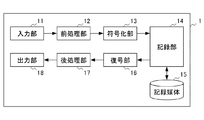
映像記録再生装置1は、入力部11と、前処理部12と、符号化部13と、記録部14と、記録媒体15と、復号部16と、後処理部17と、出力部18とを備える。
FIG. 1 is a diagram showing a functional configuration of a video recording / reproducing
The video recording / reproducing
入力部11は、外部装置から映像信号を取得する。
外部装置からの入力映像は、フル解像度、又はDG方式のスーパーハイビジョンカメラの他、CCU(カメラコントロールユニット)や、その他の映像処理装置から出力される映像信号であってもよい。
The input unit 11 acquires a video signal from an external device.
The input video from the external device may be a video signal output from a CCU (Camera Control Unit) or other video processing device in addition to a full resolution or DG Super Hi-Vision camera.
前処理部12は、第1のサンプリング構造を持つ複数の色成分で構成されるカラー方式の単一フレーム画像について、少なくとも1つの色成分をアップコンバート、ダウンコンバート又は画像変形のいずれかの方式により変換する。これにより、前処理部12は、変換された色成分を含む複数の色成分で構成される第2のサンプリング構造を持つカラー方式の単一フレーム画像を生成する。前処理部12の詳細は後述する。
The
符号化部13は、前処理部12により変換された後の画像データを、所定の圧縮方式により符号化してビットレートを圧縮する。映像の符号化は、第2のサンプリング構造に対応した規格化された公知の技術を用いることができる。
The
記録部14は、符号化部13により符号化された信号を、記録媒体15へ記録する。また、映像再生時には、記録部14は、記録媒体15から符号化された信号を読み出す。
The
復号部16は、記録媒体15より読み出した符号化信号を復号し、復号された第2のサンプリング構造を持つカラー方式の単一フレーム画像の信号を、後処理部17へ出力する。
The
後処理部17は、復号部16により復号された第2のサンプリング構造を持つカラー方式の単一フレーム画像について、少なくとも1つの色成分をアップコンバート、ダウンコンバート又は画像変形のいずれかの方式により変換する。これにより、後処理部17は、変換された色成分を含む複数の色成分で構成され、映像記録再生装置1に入力された第1のサンプリング構造を持つカラー方式の単一フレーム画像、又は第3のサンプリング構造を持つカラー方式の単一フレーム画像を生成する。後処理部17の詳細は後述する。
The
出力部18は、第1のサンプリング構造を持つカラー方式に変換された映像信号を、モニタ等の外部装置に出力する。
The
図2は、本実施形態に係る前処理部12の機能構成を示す図である。
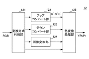
前処理部12は、変換方式判別部121と、アップコンバート部122と、ダウンコンバート部123と、画像変形部124と、色変換処理部125とを備える。
FIG. 2 is a diagram illustrating a functional configuration of the
The
変換方式判別部121は、アップコンバート、ダウンコンバート又は画像変形のいずれの方式により入力映像の変換を行うかを判別する。
このとき、変換方式判別部121は、入力映像のサンプリング構造を判別し、判別した第1のサンプリング構造の種別に応じて変換方式を判別する。
The conversion
At this time, the conversion
具体的には、変換方式判別部121は、予め設定された変換リストに従って、入力映像をアップコンバート部122、ダウンコンバート部123、又は画像変形部124に振り分ける。なお、変換リストにより、変換不要と判断されたサンプリング構造を持つ入力映像は、直接、色変換処理部125に受け渡される。
ここで、変換リストは、映像記録再生装置1の中で一意に定められていてもよいし、ユーザが外部インターフェース等を介して任意に選択できてもよい。
また、変換方式判別部121は、例えば、ユーザから指定された圧縮モード(例えば、高圧縮モード)に応じて変換方式を判別してもよい。
Specifically, the conversion
Here, the conversion list may be uniquely determined in the video recording /
Moreover, the conversion method discrimination |
アップコンバート部122は、単一フレーム画像について、いずれかの色成分における欠損画素を補間することにより、第2のサンプリング構造にアップコンバートする。変換の手法は、例えば画素補間又は超解像技術等の公知の技術を用いてよい。
The up-
ダウンコンバート部123は、単一フレーム画像について、いずれかの色成分の画素数を削減することにより、第2のサンプリング構造にダウンコンバートする。変換の手法は、例えば、画素の間引き又は複数画素の平均値化等、公知の技術を用いてよい。
The down-
画像変形部124は、単一フレーム画像について、いずれかの色成分の画素の位置を移動することにより、第2のサンプリング構造に画像変形する。変換の手法は、特定画素の入れ替え又はベクトル操作等、公知の技術を用いてよい。
The
色変換処理部125は、RGB信号(フルカラー信号)で入力された映像信号について、符号化部13により処理可能なYPbPr信号又はYCbCr信号(色差信号)に変換する。入力された画像がYPbPr信号又はYCbCr信号である場合は、色変換処理部125は、映像信号の変換を行わず出力する。なお、符号化部13の用いる符号化技術がRGB信号に対応している場合は、この色変換処理部125の変換処理が省略される。
The color
図3は、本実施形態に係る後処理部17の機能構成を示す図である。
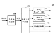
後処理部17は、色変換処理部171と、変換方式判別部172と、アップコンバート部173と、ダウンコンバート部174と、画像変形部175とを備える。
FIG. 3 is a diagram illustrating a functional configuration of the
The
色変換処理部171は、復号部16により復号されたYPbPr信号又はYCbCr信号を、RGB信号に変換する。
The color
変換方式判別部172は、出力部18により出力される映像信号のカラー方式を決定する。この出力時のカラー方式は、入力部11により入力された映像信号と同様の第1のサンプリング構造としてもよいし、ユーザが任意に第3のサンプリング構造を選択してもよい。
色変換処理部171から受け取った映像信号は、この決定に従って、アップコンバート部173、ダウンコンバート部174又は画像変形部175に振り分けられる。なお、変換不要と判断された映像信号は、直接、出力部18に受け渡される。
The conversion
The video signal received from the color
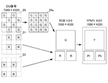
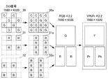
図4は、本実施形態に係るアップコンバート部122における画像変換の第1の例を示す図である。
この例では、解像度7680×4320のDG信号が入力され、アップコンバート部122は、DG信号の単一フレーム画像について、G成分のみを抽出した画像データ20のうち、R及びB領域の欠損画素を補間して解像度の高い画像データ20aを生成する。
FIG. 4 is a diagram illustrating a first example of image conversion in the up-
In this example, a DG signal having a resolution of 7680 × 4320 is input, and the up-
アップコンバート部122は、G成分の画像データ20a、R成分の画像データ21及びB成分の画像データ22をパッケージ化することで、4:2:0のサンプリング構造をもつ解像度7680×4320のカラー画像に変換している。当該サンプリング構造の場合、より好ましくは、色変換処理部125により、色差信号へと変換された画像であると、多くの規格化された公知の圧縮技術との整合性が取れる。
The up-
図5は、本実施形態に係るアップコンバート部122における画像変換の第2の例を示す図である。
この例では、解像度7680×4320のDG信号が入力され、アップコンバート部122は、DG信号の単一フレーム画像について、G成分のみを抽出した画像データ30のうち、R及びB領域の欠損画素を補間して解像度の高い画像データ20aを生成する。さらに、アップコンバート部122は、R成分の画像データ31及びB成分の画像データ32のうち、それぞれ垂直方向に隣接した領域の欠損画素を補間することで解像度の高い画像データ31a及び32aを生成する。
FIG. 5 is a diagram illustrating a second example of image conversion in the up-
In this example, a DG signal having a resolution of 7680 × 4320 is input, and the up-
アップコンバート部122は、G成分の画像データ30a、R成分の画像データ31a及びB成分の画像データ32aをパッケージ化することで、4:2:2のサンプリング構造をもつ解像度7680×4320のカラー画像に変換している。当該サンプリング構造の場合、より好ましくは、色変換処理部125により、色差信号へと変換された画像であると、多くの規格化された公知の圧縮技術との整合性が取れる。
The up-
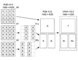
図6は、本実施形態に係るダウンコンバート部123における画像変換の一例を示す図である。
この例では、フル解像度のスーパーハイビジョンの信号が入力され、ダウンコンバート部123は、単一フレーム画像(RGB4:4:4)について、R成分のみを抽出した画像データ41の2m+1列、及びB成分のみを抽出した画像データ42の2m+2列の画素を間引くことで、解像度を落とした画像データ41a及び42aを生成する。ここで、mは0から3839までの整数を表す。
FIG. 6 is a diagram illustrating an example of image conversion in the down-
In this example, a full-resolution Super Hi-Vision signal is input, and the down-
ダウンコンバート部123は、G成分の画像データ40、R成分の画像データ41a及びB成分の画像データ42aをパッケージ化することで、4:2:2のサンプリング構造をもつ解像度7680×4320のカラー画像に変換している。当該サンプリング構造の場合、より好ましくは、色変換処理部125により、色差信号へと変換された画像であると、多くの規格化された公知の圧縮技術との整合性が取れる。
なお、ダウンコンバート部123は、R成分及びB成分について、共通の列(2m+1又は2m+2)の画素を間引いてもよい。
The down-
Note that the down-
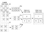
図7は、本実施形態に係る画像変形部124における画像変換の一例を示す図である。
この例では、解像度7680×4320のDG信号が入力され、画像変形部124は、DG信号の単一フレーム画像について、G成分のみを抽出した画像データ50のうち、2n+1行目及び2n+2行目のG成分を同列のn+1行目に配置することで、変形された画像データ50aを生成する。また、画像変形部124は、R生成及びB成分についても同様に、2n+1行目及び2n+2行目の成分を同列のn+1行目に配置することで、それぞれR成分の画像データ51a及びB成分の画像データ52aを生成する。ここで、nは0から2159までの整数を表す。
FIG. 7 is a diagram illustrating an example of image conversion in the
In this example, a DG signal with a resolution of 7680 × 4320 is input, and the
画像変形部124は、G成分の画像データ50a、R成分の画像データ51a及びB成分の画像データ52aをパッケージ化することで、4:2:2のサンプリング構造をもつ解像度3840×2160のカラー画像に変換している。当該サンプリング構造の場合、より好ましくは、色変換処理部125により、色差信号へと変換された画像であると、多くの規格化された公知の圧縮技術との整合性が取れる。
The
<実施例>
以下、本実施形態の効果を示すために行ったシミュレーションの手順及び結果を示す。
この例では、記録再生の対象となる元画像に、ハイビジョン画像(解像度1980×1080、8Bit)を用いたが、スーパーハイビジョン画像、又は他の高精細画像が入力された場合にも同様の結果が期待できる。
<Example>
Hereafter, the procedure and result of the simulation performed in order to show the effect of this embodiment are shown.
In this example, a high-definition image (resolution: 1980 × 1080, 8 bits) is used as an original image to be recorded and reproduced, but the same result is obtained when a super high-definition image or another high-definition image is input. I can expect.
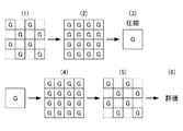
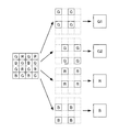
図8は、本実施形態に係る映像記録再生装置1をシミュレーションした手順を模式的に示す図である。
FIG. 8 is a diagram schematically showing a procedure for simulating the video recording / reproducing
(手順1)元画像をベイヤー型にサンプリングする(図13参照)。
(手順2)(1)でサンプリングした画像のうち、G成分について、R及びB領域の欠損画素を補間することで、アップコンバートする。
(手順3)(2)により4:2:0の方式でサンプリングされたRGB信号を符号化する。
(手順4)符号化された信号を復号する。
(手順5)復号した信号のG成分について、ベイヤー型にサンプリングする。
(手順6)入力画像のG成分と(5)で生成されたG成分とについて、PSNR(ピーク信号対雑音比)を算出して評価する。
(Procedure 1) The original image is sampled into a Bayer pattern (see FIG. 13).
(Procedure 2) Of the images sampled in (1), the G component is up-converted by interpolating the missing pixels in the R and B regions.
(Procedure 3) The RGB signals sampled by the 4: 2: 0 method according to (2) are encoded.
(Procedure 4) The encoded signal is decoded.
(Procedure 5) The G component of the decoded signal is sampled in a Bayer type.
(Procedure 6) PSNR (peak signal-to-noise ratio) is calculated and evaluated for the G component of the input image and the G component generated in (5).
図9は、本実施形態に係る映像記録再生装置1との比較対象として、従来の記録再生装置の手法をシミュレーションした手順を模式的に示す図である。
FIG. 9 is a diagram schematically showing a procedure for simulating a technique of a conventional recording / reproducing apparatus as a comparison target with the video recording / reproducing
(手順1)元画像をベイヤー型にサンプリングする。
(手順2)サンプリングした画像のうち、G成分について、2k+1行及び2k+2行の成分を空間分割して、2枚の画像に再構成する。ここで、kは0から539までの整数である。
(手順3)(2)で得られた2枚の画像の他、R成分及びB成分について、それぞれ個別に符号化する。
(手順4)符号化された信号を復号する。
(手順5)復号した2枚のG画像を合成し、元画像と同様の構成に戻す。
(手順6)入力画像のG成分と(5)で生成されたG成分とについて、PSNRを算出して評価する。
(Procedure 1) Sampling the original image into a Bayer type.
(Procedure 2) Among the sampled images, the components of 2k + 1 rows and 2k + 2 rows of the G component are spatially divided and reconstructed into two images. Here, k is an integer from 0 to 539.
(Procedure 3) In addition to the two images obtained in (2), the R component and the B component are individually encoded.
(Procedure 4) The encoded signal is decoded.
(Procedure 5) Two decoded G images are combined and returned to the same configuration as the original image.
(Procedure 6) PSNR is calculated and evaluated for the G component of the input image and the G component generated in (5).
上記2つのシミュレーションにおいて、符号化にはJPEG2000の非可逆圧縮を用いた。また、G画像のアップコンバートについては、Gradient−Linear、及びACPIの2方式を用いた。 In the above two simulations, JPEG2000 lossy compression was used for encoding. For G image up-conversion, two methods of Gradient-Linear and ACPI were used.
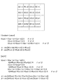
図10は、本実施形態に係るアップコンバートの2方式を説明する図である。
いずれの方式も、R画素の位置のG成分を補間する場合の式を例示した。なお、B画素の位置のG成分を補間する場合は、RをBと読み替える。
FIG. 10 is a diagram for explaining two methods of up-conversion according to the present embodiment.
In any of the methods, the equations in the case of interpolating the G component at the R pixel position are exemplified. In addition, when interpolating the G component at the position of the B pixel, R is read as B.
これらの方式では、垂直方向の非連続性を示す値αと、水平方向の非連続性を示す値βとの大小関係に応じて、周囲のG成分、又はG成分及びR成分に基づいてG成分が補間される。 In these methods, G based on the surrounding G component, or G component and R component, depending on the magnitude relationship between the value α indicating discontinuity in the vertical direction and the value β indicating discontinuity in the horizontal direction. The components are interpolated.
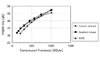
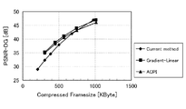
図11及び図12は、本実施形態に係るシミュレーション結果の評価値を示す図である。なお、2種類の画像データを入力とした結果をそれぞれの図で示した。 11 and 12 are diagrams showing evaluation values of simulation results according to the present embodiment. The results of inputting two types of image data are shown in the respective drawings.
横軸は符号化した画像のフレームサイズを示し、縦軸はベイヤー配列のG成分についての元画像とのPSNRを示している。フレームサイズが小さいほど圧縮率が高く、PSNRが大きいほど元画像の再現性が高い。
本実施形態による手法(Gradient−Linear又はACPI)を用いた場合、特に高圧縮率の符号化を行った際のPSNRの劣化が、従来手法(Current method)と比較して改善されている。
The horizontal axis represents the frame size of the encoded image, and the vertical axis represents the PSNR with the original image for the G component of the Bayer array. The smaller the frame size, the higher the compression ratio, and the larger the PSNR, the higher the reproducibility of the original image.
When the method according to the present embodiment (Gradient-Linear or ACPI) is used, PSNR degradation particularly when encoding at a high compression rate is improved compared to the conventional method (Current method).
本実施形態によれば、映像記録再生装置1は、入力映像を、入力時と異なるサンプリング構造を持つカラー方式の単一フレーム画像として取り扱うことにより、単一フレーム画像を空間的に複数の画像に分割することなく、単一の画像データとして記録媒体に記録できる。これにより、映像記録再生装置1は、画像データを分散させず、効率的に高精細映像を扱えるので、記録媒体の管理や、記録した画像データの管理、運用が容易になる。
According to the present embodiment, the video recording /
また、映像記録再生装置1は、本来の画像の持つ連続性を保ちつつ符号化技術を適用できるため、圧縮効率が向上し、非可逆プロセスによる符号化を行った場合でも、圧縮ひずみを抑えることが可能となる。
In addition, since the video recording / reproducing
さらに、映像記録再生装置1により記録された画像データは、記録媒体中では、規格化されたサンプリング構造をもつ単一の符号化信号として取り扱うことができるため、記録データが分散せず、規格化された効率的な符号化及び復号の技術を用いて記録データの閲覧、整理及びバックアップといった作業を容易に行うことが可能である。また、記録映像の再生時は、複数の記録媒体に分散されたデータを同期して読みだすためのタイミング同期回路が不要となるため、装置構成が複雑になるのを防ぐことができる。
Furthermore, since the image data recorded by the video recording / reproducing
また、映像記録再生装置1は、入力映像信号のカラー方式に応じて、前処理部12の画像変換アルゴリズムを変更し、同一のサンプリング構造を持つ映像信号を、符号化部13に入力できる。このようにすることで、異なる入力映像信号のカラー方式に対して、符号化部13及び復号部16では同一の映像符号化技術を適用できるため、符号化部13及び復号部16の回路構成を単純化でき、様々な入力信号に対応した、小型の映像記録再生装置1を実現できる。
さらに、映像記録再生装置1は、サンプリング構造の種別に応じて、又は指定された圧縮モードに応じて変換方式を判別するので、複数のカラー方式に自動で対応でき、利便性が向上する。
Further, the video recording / reproducing
Further, since the video recording / reproducing
また、映像記録再生装置1は、フレーム順序の入れ替え及び色調整等の機能を付加することで、映像編集機を実現できる。この映像編集機は、従来の記録装置のように、複数の記録媒体又は複数の記録領域への並列処理を必要としないため、高速処理が可能である。
Further, the video recording /
以上、本発明の実施形態について説明したが、本発明は前述した実施形態に限るものではない。また、本実施形態に記載された効果は、本発明から生じる最も好適な効果を列挙したに過ぎず、本発明による効果は、本実施形態に記載されたものに限定されるものではない。 As mentioned above, although embodiment of this invention was described, this invention is not restricted to embodiment mentioned above. Further, the effects described in the present embodiment are merely a list of the most preferable effects resulting from the present invention, and the effects of the present invention are not limited to those described in the present embodiment.
前述の実施形態では、映像の記録機能及び再生機能の双方を備えた映像記録再生装置1を説明したが、これには限られない。
例えば、復号部16、後処理部17及び出力部18は、別の再生装置として分離されてもよい。また、記録部14及び記録媒体15が別の装置として分離されてもよい。
In the above-described embodiment, the video recording /
For example, the
前述した映像記録再生装置1は、主にDG方式又はフル解像度のスーパーハイビジョン映像の記録再生装置として説明したが、本発明は、4K又は他の高解像度映像システム、及び一眼レフカメラ等の単板撮像素子等に広く応用が可能である。
The video recording / reproducing
本実施形態では、主に映像記録再生装置の構成と動作について説明したが、本発明はこれに限られず、各構成要素を備え、映像を記録及び再生するための方法、又はプログラムとして構成されてもよい。 In the present embodiment, the configuration and operation of the video recording / playback apparatus have been mainly described. However, the present invention is not limited to this, and includes each component, and is configured as a method or program for recording and playing back video. Also good.
さらに、映像記録再生装置の機能を実現するためのプログラムをコンピュータで読み取り可能な記録媒体に記録して、この記録媒体に記録されたプログラムをコンピュータシステムに読み込ませ、実行することによって実現してもよい。 Further, the present invention may be realized by recording a program for realizing the function of the video recording / reproducing apparatus on a computer-readable recording medium, causing the computer system to read and execute the program recorded on the recording medium. Good.
ここでいう「コンピュータシステム」とは、OSや周辺機器等のハードウェアを含むものとする。また、「コンピュータで読み取り可能な記録媒体」とは、フレキシブルディスク、光磁気ディスク、ROM、CD−ROM等の可搬媒体、コンピュータシステムに内蔵されるハードディスク等の記憶装置のことをいう。 The “computer system” here includes an OS and hardware such as peripheral devices. The “computer-readable recording medium” refers to a storage device such as a portable medium such as a flexible disk, a magneto-optical disk, a ROM, and a CD-ROM, and a hard disk built in the computer system.
さらに「コンピュータで読み取り可能な記録媒体」とは、インターネット等のネットワークや電話回線等の通信回線を介してプログラムを送信する場合の通信線のように、短時刻の間、動的にプログラムを保持するもの、その場合のサーバやクライアントとなるコンピュータシステム内部の揮発性メモリのように、一定時刻プログラムを保持しているものも含んでもよい。また、上記プログラムは、前述した機能の一部を実現するためのものであってもよく、さらに前述した機能をコンピュータシステムにすでに記録されているプログラムとの組み合わせで実現できるものであってもよい。 Furthermore, “computer-readable recording medium” means that a program is dynamically held for a short time, like a communication line when transmitting a program via a network such as the Internet or a communication line such as a telephone line. It is also possible to include one that holds a program for a certain time, such as a volatile memory inside a computer system that becomes a server or client in that case. Further, the program may be for realizing a part of the above-described functions, and may be capable of realizing the above-described functions in combination with a program already recorded in the computer system. .
1 映像記録再生装置(映像記録装置、映像再生装置)
11 入力部
12 前処理部(第1変換部)
13 符号化部
14 記録部
15 記録媒体
16 復号部
17 後処理部(第2変換部)
18 出力部
121 変換方式判別部
122 アップコンバート部
123 ダウンコンバート部
124 画像変形部
125 色変換処理部
171 色変換処理部
172 変換方式判別部
173 アップコンバート部
174 ダウンコンバート部
175 画像変形部
1. Video recording / playback device (video recording device, video playback device)
11
13
DESCRIPTION OF
Claims (5)
前記第1変換部により変換された後の画像データを、所定の圧縮方式により符号化する符号化部と、を備える映像記録装置。 The sampling structure of a dual green for a single frame image of lifting poked color scheme, the green color component and up-converting DOO, by image deformation the color components red and blue, 4: 2: 0 sampling structure A first conversion unit for converting into a single frame image of a color system having;
An image recording apparatus comprising: an encoding unit that encodes the image data converted by the first conversion unit by a predetermined compression method.
前記第1変換部により変換された後の画像データを、所定の圧縮方式により符号化する符号化部と、を備える映像記録装置。 The sampling structure of a dual green for a single frame image of lifting poked color scheme, green, by up-converting each color component of red and blue, 4: 2: single frame of a color system having a second sampling structure A first conversion unit for converting into an image;
An image recording apparatus comprising: an encoding unit that encodes the image data converted by the first conversion unit by a predetermined compression method.
前記第1変換部により変換された後の画像データを、所定の圧縮方式により符号化する符号化部と、を備える映像記録装置。 The sampling structure of a dual green for a single frame image of lifting poked color scheme, green, by each image deformation the color components red and blue, 4: 2: single frame of a color system having a second sampling structure A first conversion unit for converting into an image;
An image recording apparatus comprising: an encoding unit that encodes the image data converted by the first conversion unit by a predetermined compression method.
前記復号部により復号された画像データについて、緑、赤及び青の色成分をそれぞれ変換し、前記デュアルグリーンのサンプリング構造を持つカラー方式の単一フレーム画像に変換する第2変換部と、を備える映像再生装置。 The video recording apparatus according to any one of claims 1 to 3, a decoding unit for decoding the image picture data encoded by said predetermined compression method,
The image data decoded by said decoding unit includes green, the color components of the red and blue converted respectively, and a second conversion unit that converts the single frame image of a color scheme with a sampling structure of the dual green, a Video playback device.
Priority Applications (1)
| Application Number | Priority Date | Filing Date | Title |
|---|---|---|---|
| JP2014086589A JP6316640B2 (en) | 2014-04-18 | 2014-04-18 | VIDEO RECORDING DEVICE, VIDEO REPRODUCTION DEVICE, AND VIDEO RECORDING PROGRAM |
Applications Claiming Priority (1)
| Application Number | Priority Date | Filing Date | Title |
|---|---|---|---|
| JP2014086589A JP6316640B2 (en) | 2014-04-18 | 2014-04-18 | VIDEO RECORDING DEVICE, VIDEO REPRODUCTION DEVICE, AND VIDEO RECORDING PROGRAM |
Publications (2)
| Publication Number | Publication Date |
|---|---|
| JP2015207874A JP2015207874A (en) | 2015-11-19 |
| JP6316640B2 true JP6316640B2 (en) | 2018-04-25 |
Family
ID=54604387
Family Applications (1)
| Application Number | Title | Priority Date | Filing Date |
|---|---|---|---|
| JP2014086589A Active JP6316640B2 (en) | 2014-04-18 | 2014-04-18 | VIDEO RECORDING DEVICE, VIDEO REPRODUCTION DEVICE, AND VIDEO RECORDING PROGRAM |
Country Status (1)
| Country | Link |
|---|---|
| JP (1) | JP6316640B2 (en) |
Family Cites Families (9)
| Publication number | Priority date | Publication date | Assignee | Title |
|---|---|---|---|---|
| JP2004120499A (en) * | 2002-09-27 | 2004-04-15 | Victor Co Of Japan Ltd | Device for encoding and decoding moving image |
| JP2006333254A (en) * | 2005-05-27 | 2006-12-07 | Fujifilm Holdings Corp | Moving image real time communication terminal, and method and program for controlling moving image real time communication terminal |
| JP2008053800A (en) * | 2006-08-22 | 2008-03-06 | Pentax Corp | Digital camera |
| US8428120B2 (en) * | 2007-12-11 | 2013-04-23 | Taiwan Imagingtek Corporation | Method and apparatus of Bayer pattern direct video compression |
| EP2144432A1 (en) * | 2008-07-08 | 2010-01-13 | Panasonic Corporation | Adaptive color format conversion and deconversion |
| JP2010268335A (en) * | 2009-05-18 | 2010-11-25 | Panasonic Corp | Recording / playback system |
| JP5140637B2 (en) * | 2009-06-22 | 2013-02-06 | 日本放送協会 | Spatiotemporal downsampling processing device, spatiotemporal upsampling processing device, encoding device, decoding device, and program |
| JP5956813B2 (en) * | 2012-04-11 | 2016-07-27 | キヤノン株式会社 | Image processing apparatus and control method thereof |
| US9641875B2 (en) * | 2012-09-04 | 2017-05-02 | Nippon Hoso Kyokai | Video signal transmitting device, video signal receiving device, and recording medium |
-
2014
- 2014-04-18 JP JP2014086589A patent/JP6316640B2/en active Active
Also Published As
| Publication number | Publication date |
|---|---|
| JP2015207874A (en) | 2015-11-19 |
Similar Documents
| Publication | Publication Date | Title |
|---|---|---|
| US10574898B2 (en) | Compression and decoding of single sensor color image data | |
| US11270470B2 (en) | Color leaking suppression in anchor point cloud compression | |
| US7933462B2 (en) | Representing and reconstructing high dynamic range images | |
| US7940990B2 (en) | Image signal processing apparatus and image signal processing method | |
| EA032859B1 (en) | Tiered signal decoding and signal reconstruction | |
| US9438920B2 (en) | Picture encoding method, picture encoding apparatus, picture decoding method and picture decoding apparatus | |
| US8358363B2 (en) | Video-processing apparatus, method and system | |
| WO2019130794A1 (en) | Video processing device | |
| JP4012201B2 (en) | Image data compression apparatus and restoration apparatus, and image data compression program and restoration program | |
| CN102769732B (en) | A kind of conversion method for realizing video field | |
| JP2013048307A (en) | Moving picture decoder and moving picture decoding method | |
| KR101551915B1 (en) | Device and method for video compression | |
| JPWO2017203941A1 (en) | IMAGE PROCESSING APPARATUS, IMAGE PROCESSING METHOD, AND PROGRAM | |
| JP6316640B2 (en) | VIDEO RECORDING DEVICE, VIDEO REPRODUCTION DEVICE, AND VIDEO RECORDING PROGRAM | |
| JP6460691B2 (en) | Video compression apparatus, video compression method, and video compression program | |
| CN100592778C (en) | Recording and playback device and method, recording device and playback device and method | |
| JP3774988B2 (en) | Still image capturing apparatus, color copying apparatus, and display apparatus | |
| JP5175796B2 (en) | Encoding / preprocessing device, decoding / postprocessing device, encoding device, decoding device, and program | |
| KR20060099026A (en) | Image magnification processing method | |
| JP2017058739A (en) | Information processing system and information processing method | |
| KR20140077754A (en) | Apparatus for parallel processing of large-scale video data and method thereof |
Legal Events
| Date | Code | Title | Description |
|---|---|---|---|
| A621 | Written request for application examination |
Free format text: JAPANESE INTERMEDIATE CODE: A621 Effective date: 20170227 |
|
| A977 | Report on retrieval |
Free format text: JAPANESE INTERMEDIATE CODE: A971007 Effective date: 20171205 |
|
| A131 | Notification of reasons for refusal |
Free format text: JAPANESE INTERMEDIATE CODE: A131 Effective date: 20171219 |
|
| A521 | Written amendment |
Free format text: JAPANESE INTERMEDIATE CODE: A523 Effective date: 20180215 |
|
| TRDD | Decision of grant or rejection written | ||
| A01 | Written decision to grant a patent or to grant a registration (utility model) |
Free format text: JAPANESE INTERMEDIATE CODE: A01 Effective date: 20180227 |
|
| A61 | First payment of annual fees (during grant procedure) |
Free format text: JAPANESE INTERMEDIATE CODE: A61 Effective date: 20180328 |
|
| R150 | Certificate of patent or registration of utility model |
Ref document number: 6316640 Country of ref document: JP Free format text: JAPANESE INTERMEDIATE CODE: R150 |