JP6316038B2 - Heat shield plate - Google Patents
Heat shield plate Download PDFInfo
- Publication number
- JP6316038B2 JP6316038B2 JP2014053921A JP2014053921A JP6316038B2 JP 6316038 B2 JP6316038 B2 JP 6316038B2 JP 2014053921 A JP2014053921 A JP 2014053921A JP 2014053921 A JP2014053921 A JP 2014053921A JP 6316038 B2 JP6316038 B2 JP 6316038B2
- Authority
- JP
- Japan
- Prior art keywords
- heat shield
- metal plates
- shield plate
- heat insulating
- punched
- Prior art date
- Legal status (The legal status is an assumption and is not a legal conclusion. Google has not performed a legal analysis and makes no representation as to the accuracy of the status listed.)
- Active
Links
- 229910052751 metal Inorganic materials 0.000 claims description 92
- 239000002184 metal Substances 0.000 claims description 92
- 239000011810 insulating material Substances 0.000 claims description 49
- 238000003466 welding Methods 0.000 claims description 6
- 238000005304 joining Methods 0.000 claims description 5
- 239000000853 adhesive Substances 0.000 description 5
- 230000001070 adhesive effect Effects 0.000 description 5
- 239000000463 material Substances 0.000 description 5
- 239000003054 catalyst Substances 0.000 description 4
- 230000002093 peripheral effect Effects 0.000 description 4
- 229910052782 aluminium Inorganic materials 0.000 description 3
- XAGFODPZIPBFFR-UHFFFAOYSA-N aluminium Chemical compound [Al] XAGFODPZIPBFFR-UHFFFAOYSA-N 0.000 description 3
- 238000000034 method Methods 0.000 description 3
- 238000003825 pressing Methods 0.000 description 3
- 238000011144 upstream manufacturing Methods 0.000 description 3
- 229910000831 Steel Inorganic materials 0.000 description 2
- 239000003822 epoxy resin Substances 0.000 description 2
- 239000000835 fiber Substances 0.000 description 2
- 239000003365 glass fiber Substances 0.000 description 2
- 239000002241 glass-ceramic Substances 0.000 description 2
- 238000004806 packaging method and process Methods 0.000 description 2
- 239000005011 phenolic resin Substances 0.000 description 2
- 229920000647 polyepoxide Polymers 0.000 description 2
- 238000004080 punching Methods 0.000 description 2
- 229910001220 stainless steel Inorganic materials 0.000 description 2
- 239000010959 steel Substances 0.000 description 2
- 229910000838 Al alloy Inorganic materials 0.000 description 1
- 229910000640 Fe alloy Inorganic materials 0.000 description 1
- 238000005452 bending Methods 0.000 description 1
- 238000002716 delivery method Methods 0.000 description 1
- 230000000694 effects Effects 0.000 description 1
- 239000012774 insulation material Substances 0.000 description 1
- 239000012212 insulator Substances 0.000 description 1
- 238000007726 management method Methods 0.000 description 1
- 239000007769 metal material Substances 0.000 description 1
- 238000012856 packing Methods 0.000 description 1
- 239000010935 stainless steel Substances 0.000 description 1
Images


Description
本発明は、例えば、エンジンから排出され、エキゾーストマニホールドを通過した排気ガス、或いはターボチャージャーを構成するタービンを通過した排気ガスを、触媒及びマフラーに導く為の排気管等の様に、運転時に高温となる部分を覆う状態で設置する遮熱板の改良に関する。 The present invention provides a high temperature during operation, such as an exhaust pipe for guiding exhaust gas discharged from an engine and passing through an exhaust manifold or passing through a turbine constituting a turbocharger to a catalyst and a muffler. The present invention relates to an improvement of a heat shield installed in a state of covering a portion to be.
自動車用エンジンのシリンダヘッドの側面にその上流端部を接続したエキゾーストマニホールドを通過した排気ガスを、下流側に配置された触媒及びマフラーに導く為の排気管等の部材の温度は、内部を流れる排気の熱により、相当に上昇する。この様に温度上昇した前記排気管から放射される輻射熱から、エンジンルーム内に設けた他の機器等を保護する為に、前記排気管をヒートインシュレータと呼ばれる遮熱板により覆い、この排気管からの輻射熱が前記他の機器等に伝わるのを防止している。エンジンに過給する為のターボチャージャーに関しても同様である。 The temperature of a member such as an exhaust pipe that guides exhaust gas that has passed through an exhaust manifold having an upstream end connected to a side surface of a cylinder head of an automobile engine to a catalyst and a muffler disposed on the downstream side flows inside. The temperature rises considerably due to the heat of the exhaust. In order to protect other equipment and the like provided in the engine room from radiant heat radiated from the exhaust pipe whose temperature has increased in this way, the exhaust pipe is covered with a heat shield plate called a heat insulator, Is prevented from being transmitted to the other devices. The same applies to the turbocharger for supercharging the engine.
図4〜6は、特許文献1に記載された遮熱板1の従来構造の1例を示している。この遮熱板1は、全体が筒状に形成されており、上流側に配置されたエンジン(図示省略)からの排気ガスを、下流側に配置された触媒及びマフラー(図示省略)に導く為の排気管2の外周面の一部を覆う状態で設けられるものである。この様な遮熱板1は、1対の半円筒状の遮熱板素子3a、3bから成る。これら両遮熱板素子3a、3bは、半円筒状の金属板4a、4bと、これら各金属板4a、4bの内面(組み付け状態で、排気管2に近い面)に、その外面(組み付け状態で、排気管2から遠い面)が当接した状態で設けられる半円筒状の断熱材5a、5bとから成る。
4 to 6 show an example of the conventional structure of the
このうちの各金属板4a、4bは、鋼板やアルミニウム板の単板、或いは積層板をプレス加工する事により、その内側に前記各断熱材5a、5bを配置できる程度の隙間を介在させた状態で前記排気管2を覆える様な形状及び大きさに形成されている。又、前記各金属板4a、4bの円周方向両端部には、軸方向の全長に亙り、径方向外方に延出した状態で、取付フランジ部6a、6bが形成されている。又、これら各取付フランジ部6a、6bには、軸方向に離隔した状態で、複数個の貫通孔7、7が形成されている。
Each of the
又、前記各断熱材5a、5bは、フェノール樹脂、エポキシ樹脂、或はこれらを主成分とし、ガラス繊維、セラミック繊維類を混入したもの等により、その内側に、前記排気管2を隙間のない状態で覆える様な形状及び大きさに形成されている。
上述の様な両遮熱板素子3a、3bは、前記排気管2を覆う様に、前記各金属板4a、4bの各取付フランジ部6a、6b同士を円周方向に対向させた状態で、これら各取付フランジ部6a、6bの各貫通孔7、7に挿通したボルト8、8と、これら各ボルト8、8の先端部に螺合したナット9、9により結合固定されている。
Further, each of the
Both the heat
ところで、上述の様な構成を有する遮熱板1を自動車メーカ等に納品する場合、前記各金属板4a、4bと各断熱材5a、5bとを、別体として納品するか、或いは、これら各金属板4a、4bの内側に前記各断熱材5a、5bを配置した状態(組み合わせた状態)で納品している。何れの納品方法の場合でも、前記各金属板4a、4bの内側に前記各断熱材5a、5bを配置した状態で、これら各金属板4a、4bと各断熱材5a、5bとが、結合されていない為、前記排気管2に組み付ける際、前記各断熱材5a、5bが、前記各金属板4a、4bに対してずれたり、或いはこれら各金属板4a、4bから落下する等して、組み付け作業の効率が低下してしまう可能性がある。これに対して、例えば前記断熱材5a、5bを、前記各金属板4a、4bに対し、接着材により結合する事も考えられるが、この場合には、結合するまで(接着剤が乾くまで)に要する時間が長くなると共に、接着剤自体のコストが嵩み、好ましくない。
By the way, when the
又、上述の様に、前記各金属板4a、4bと前記各断熱材5a、5bとを別体として納品する場合には、輸送コスト及び部品管理コストが嵩んでしまう。一方、前記各金属板4a、4bの内側に前記各断熱材5a、5bを組み合わせた状態で納品する場合でも、梱包の際、これら両部材4a(4b)、5a(5b)同士が分離しない様に注意を払いながら行う必要があり、作業効率が低下してしまう。何れにしても、納品の為のコスト(納品コスト)が嵩んでしまう可能性がある。
Further, as described above, when the
本発明は、上述の様な事情に鑑みて、納品コストの低減及び組み付け性の向上を図れる、遮熱板の構造を実現すべく発明したものである。 The present invention has been invented to realize a structure of a heat shield plate capable of reducing the delivery cost and improving the assemblability in view of the above-described circumstances.
本発明の遮熱板は、プレス加工により使用時に高温となる部材の少なくとも一部を覆える形状に形成された部分筒状(例えば半筒状)の金属板と、この金属板の内側(組み付け状態で、高温となる部材に近い側)に、この金属板と当接した状態で配置されており、その内面が前記高温となる部材の外面に当接した状態(好ましくは押し付けられた状態)で使用されるものである部分筒状の断熱材と、1対の打ち抜き部を有するステープルとを備えている。
又、前記金属板と前記断熱材とが、これら金属板及び断熱材を外側(組み付け状態で、高温となる部材から遠い側)から打ち抜いた状態で固定された前記ステープルにより、互いに結合されている。
更に、前記金属板の外面のうち、前記ステープルを打ち抜く部分に、底部が平坦面状の凹部が設けられており、前記底部が前記1対の打ち抜き部同士の距離よりも大きくなっている。
The heat shield plate of the present invention includes a partially cylindrical (for example, semi-cylindrical) metal plate formed in a shape that covers at least a part of a member that becomes hot during use by press working, and an inner side (assembly ) of the metal plate. In a state close to the high temperature member) in contact with the metal plate, and the inner surface is in contact with the outer surface of the high temperature member (preferably pressed) those with part cylindrical insulation material is used in, and a staple having a punched portion of the pair.
Further, the metal plate and the heat insulating material are coupled to each other by the staple fixed in a state in which the metal plate and the heat insulating material are punched from the outside (the side far from the high temperature member in the assembled state) . .
Furthermore, a concave portion having a flat bottom surface is provided in a portion of the outer surface of the metal plate where the staple is punched, and the bottom portion is larger than the distance between the pair of punched portions.
上述の様な本発明の遮熱板を実施する場合には例えば、請求項2に記載した発明の様に、前記底部の厚さ寸法を、他の部分の厚さ寸法よりも小さくする事ができる。
本発明を実施する場合には例えば、請求項3に記載した発明の様に、前記凹部を円形とし、前記底部の直径を前記1対の打ち抜き部同士の距離よりも大きくする事ができる。
本発明を実施する場合には例えば、請求項4に記載した発明の様に、前記遮熱板を、半筒状(例えば、半円筒状)の一対の遮熱板素子により構成する。又、これら両遮熱板素子を、1対の半筒状の金属板と、1対の半筒状の断熱材とにより構成する。そして、これら両金属板を、これら両金属板の円周方向両端部を対向させた状態で結合する事により、全体を筒状に形成する。尚、前記遮熱板を、部分筒状の複数(3個以上)の遮熱板素子(金属板及び断熱材)により構成する事も可能である。
請求項4に記載された発明を実施する場合には例えば、請求項5に記載した発明の様に、前記各金属板の円周方向両端部に、径方向外方に延出した状態で取付フランジ部を形成する。そして、前記各金属板のこれら各取付フランジ部同士を円周方向に対向させた状態で、これら各取付フランジ部同士を溶接又はかしめにより結合固定する。
When implementing the heat shield plate of the present invention as described above, for example, as in the invention described in
In the case of carrying out the present invention, for example, as in the invention described in claim 3, the concave portion can be circular, and the diameter of the bottom portion can be made larger than the distance between the pair of punched portions .
In the case of carrying out the present invention, for example, as in the invention described in claim 4, the heat shield plate is constituted by a pair of heat shield plate elements having a semi-cylindrical shape (for example, a semi-cylindrical shape). Further, both the heat shield plate elements are constituted by a pair of semi-cylindrical metal plates and a pair of semi-cylindrical heat insulating materials. Then, these two metal plates are joined together in a state where both ends in the circumferential direction of these two metal plates are opposed to each other, so that the whole is formed into a cylindrical shape. The heat shield plate may be constituted by a plurality of (three or more) heat shield plate elements (metal plate and heat insulating material) that are partially cylindrical.
When the invention described in claim 4 is carried out, for example, as in the invention described in claim 5, it is attached to both ends in the circumferential direction of each metal plate in a state of extending radially outward. Form a flange. Then, in a state where the mounting flange portions of the metal plates are opposed to each other in the circumferential direction, the mounting flange portions are coupled and fixed by welding or caulking.
本発明の遮熱板の場合、遮熱板を構成する金属板と断熱材とを、この金属板を外側から打ち抜く事により固定されたステープルにより互いに結合している。この為、これら金属板と断熱材とを分離不能に結合した状態で、自動車メーカ等に納品する為の梱包及び輸送を行う事ができる。この結果、遮熱板の納品コストの低減を図れる。又、接着剤を使用して結合する場合に比べて、結合作業に要する時間を短くできると共に、材料コストを抑える事もできる。
又、前記遮熱板を、排気管等の使用時に高温となる部材に対して組み付ける際、前記金属板と前記断熱材とが分離する事がない。この為、遮熱板の組み付け性を向上でき、組み立て作業効率の向上を図れる。
In the case of the heat shield plate of the present invention, the metal plate and the heat insulating material constituting the heat shield plate are joined to each other by staples fixed by punching the metal plate from the outside. For this reason, it is possible to carry out packaging and transportation for delivery to an automobile manufacturer or the like in a state where the metal plate and the heat insulating material are inseparably coupled. As a result, the delivery cost of the heat shield can be reduced. In addition, the time required for the joining work can be shortened and the material cost can be reduced as compared with the case of joining using an adhesive.
Further, when the heat shield plate is assembled to a member that becomes high temperature when an exhaust pipe or the like is used, the metal plate and the heat insulating material are not separated. For this reason, the assembly | attachment property of a heat shield board can be improved and the improvement of assembly work efficiency can be aimed at.
[実施の形態の1例]
本発明の実施の形態の第1例に就いて、図1〜3を参照しつつ説明する。
本例の遮熱板1aは、前述した従来構造と同様に、上流側に配置されたエンジンから排出され、エキゾーストマニホールドを通過した排気ガス、或いはターボチャージャーを構成するタービンを通過した排気ガスを、下流側に配置された触媒及びマフラーに導く為の排気管2(図4〜6参照)等の様に、運転時に高温となる部分を覆う状態で設置されるものである。
[Example of Embodiment]
A first example of the embodiment of the present invention will be described with reference to FIGS.
As in the conventional structure described above, the heat shield plate 1a of the present example is exhausted from an engine disposed on the upstream side and passed through an exhaust manifold or exhaust gas passed through a turbine constituting a turbocharger. Like the exhaust pipe 2 (see FIGS. 4 to 6) and the like arranged for the catalyst and the muffler arranged on the downstream side, it is installed so as to cover a portion that becomes hot during operation.
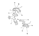
この様な本例の遮熱板1aは、1対の半円筒状の遮熱板素子3c、3dから成る。又、これら両遮熱板素子3c、3dは、半円筒状の金属板4c、4dと、これら各金属板4c、4dの内側(組み付け状態で排気管2に近い側)に、その外面(組み付け状態で排気管2から遠い面)が前記各金属板4c、4dの内面と当接した状態で配置された半円筒状の断熱材5c、5dと、複数個(本例の場合2個)のステープル10、10とから成る。
Such a heat shield plate 1a of this example includes a pair of semi-cylindrical heat
このうちの各金属板4c、4dは、厚さ寸法が0.15〜0.3mmの鋼板やアルミニウム板の単板をプレス加工する事により、その内側に前記各断熱材5c、5dを配置できる程度の隙間を介在させた状態で、前記排気管2を覆える様な形状及び大きさに形成されている。尚、前記各金属板4c、4dを、アルミニウム板により造る場合には、厚さ寸法を0.3mm程度にするのが好ましい。一方、前記各金属板4c、4dを、SUS430等のフェライト系ステンレス鋼板により造る場合には、厚さ寸法を0.2mm程度にするのが好ましい。
Each of the
この様な各金属板4c、4dの材料及び厚さ寸法は、後述するステープル10、10を打ち抜く事が可能な範囲で、適宜設定する事ができる。或いは、これら各ステープル10、10を打ち抜く部分の厚さ寸法を、他の部分に比べて予め小さくしておくこともできる。具体的には、前記各ステープル10、10を打ち抜く部分の周囲に、例えば、プレス加工により円形の凹部(図示省略)を形成し、当該部分の厚さを、他の部分の厚さ寸法よりも小さくする。この様な凹部を形成すれば、前記各ステープル10、10の打ち抜きが容易に行えるだけでなく、これら各ステープル10、10を打ち抜く位置の確認を容易に行う事もできる。尚、前記各金属板4c、4dに前記凹部を形成した場合に、この凹部の底部の厚さ寸法を他の部分の厚さ寸法と同じに形成したとしても、前記各ステープル10、10を打ち抜く位置の確認を容易に行えると言った効果を得る事ができる。
The material and thickness dimension of each of the
又、前記各金属板4c、4dの円周方向両端部には、軸方向の全長に亙り、径方向外方に延出した状態で、取付フランジ部6c、6dが形成されている。尚、本例の場合、これら各取付フランジ部6c、6dに、前述した従来構造の様な貫通孔7、7(図4〜6)は
形成していない。
Further, mounting
又、前記各断熱材5c、5dは、フェノール樹脂、エポキシ樹脂、或はこれらを主成分とし、ガラス繊維、セラミック繊維類を混入したもの等により、その内側に、前記排気管2を隙間のない状態で覆える様な形状及び大きさに形成されている。一般的に、前記各断熱材5a、5bの厚さ寸法は、前記各金属板4c、4dの厚さ寸法よりも十分に大きい。
前記各断熱材5a、5bの厚さ寸法W(図示省略)は、前記各金属板4c、4d同士を結合した状態での内径寸法D1(図示省略)と、前記排気管2の外径寸法D2(図示省略)との差の1/2よりも、大きくするのが好ましい{W>(D1−D2)/2}。この様な寸法関係に規制する事により、組み付け状態に於いて、前記各金属板4c、4dの内面と、前記排気管2の外周面との間に、前記各断熱材5a、5bを、圧縮した状態(弾性力を有した状態)で配置できる。
Further, each of the
A thickness dimension W (not shown) of each of the
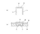
又、前記各ステープル10、10は、鉄系合金、アルミニウム合金、又はステンレス鋼等の金属材料から造られたもので、前記各金属板4c、4dと前記各断熱材5c、5dとを互いに結合する為のものである。具体的には、前記各ステープル10、10は、前記各金属板4c、4dと各断熱材5c、5dとを、これら各金属板4c、4dの円周方向中間部で、軸方向に離隔した複数箇所(本例の場合2箇所)を、外面側から打ち抜いた状態で結合している。又、本例の場合には、前記各ステープル10、10(連続部12)の長さ方向を、前記各遮熱板素子3c、3dの軸方向に一致させた状態(外周面の母線形状に沿った状態)で、前記各ステープル10、10を打ち抜いている。この様にして、これら各ステープル10、10と前記各金属板4c、4dの外面との間に隙間が形成される事を防止している。尚、前述した様に、前記各金属板4c、4dの外面のうち、ステープル10、10を打ち付ける部分に、凹部を形成すると共に、この凹部の底部を平坦面状に形成すれば、前記各ステープル10、10(連続部12)の長さ方向を、特に規制しなくても(遮熱板素子3c、3dの軸方向に一致させなくても)、これら各ステープル10、10と前記各金属板4c、4dの外面との間に隙間が形成される事を防止できる。
The
この様な各ステープル10、10は、打ち付け前の状態では、図3(a)に示す様に、全体をコ字状に形成されており、1対の打ち抜き部11、11と、これら両打ち抜き部11、11の基端部同士を連結する連続部12とから成る。一方、前記各ステープル10、10は、打ち付け状態では、前記両打ち抜き部11、11の中間部から先端部に掛けての部分が、これら両打ち抜き部11、11同士が互いに近づく方向に、半円弧状に折れ曲がっている。但し、打ち付け状態での前記両打ち抜き部11、11の形状は、後述するダイスの形状に応じて変化する為、半円弧状に限らず、例えば直角に折れ曲がった形状も採用できる。前記打ち抜き部11、11及び前記連続部12の形状は、本例の場合に限定されず、各種形状のものを採用できる。
Each of the
尚、上述の様な各ステープル10、10の打ち付けは以下の様にして行う。
先ず、前記各金属板4c、4dの内側に前記各断熱材5c、5dを配置した状態で、これら各断熱材5c、5dの内側に、図示しないダイスを配置する。そして、この状態で、図示しないエアカッター等の打ち付け工具により、前記各ステープル10、10を、前記各金属板4c、4dの外面側から打ち付けて、これら各金属板4c、4d及び各断熱材5c、5dを同時に打ち抜く。すると、前記各ステープル10、10の先端部から中間部に掛けての部分が、前記ダイスに形成された凹溝に沿う様にして、互いに近付く方向に湾曲しながら折れ曲がる。尚、前記各ステープル10、10により、前記各金属板4c、4dと前記各断熱材5c、5dとを互いに結合する作業は、前記両遮熱板素子3c、3dを自動車メーカ等に納品する前の段階で行う。即ち、納品の為の梱包及び輸送は、前記各ステープル10、10により、前記各金属板4c、4dと前記各断熱材5c、5dとを互いに結合した状態で行う事ができる。
The
First, in a state where the
上述の様な構成を有する本例の遮熱板1a(両遮熱板素子3c、3d)を、前記排気管2に組み付ける作業に就いて説明する。
先ず、前記両遮熱板素子3c、3dを、これら両遮熱板素子3c、3dを構成する各金属板4c、4dの取付フランジ部6c、6c(6d、6d)同士を円周方向に対向させ、前記各断熱材5c、5dを前記排気管2の外周面に押し付けた状態で、この排気管2を覆う様に配置する。そして、円周方向に対向した前記各取付フランジ部6c、6c(6d、6d)同士を、スポット溶接により結合固定する。
The operation of assembling the heat shield plate 1a (both heat
First, the heat
尚、スポット溶接の代わりにこれら各取付フランジ部6c、6c(6d、6d)同士をかしめ固定により結合固定する事もできる。具体的には、前記各金属板4c、4dの取付フランジ部6c、6c(6d、6d)同士を円周方向に対向させた状態で、これら両取付フランジ部6c、6c(6d、6d)の径方向外端寄り部分の一部又は全部を、同時に180°折り曲げる様にして行う。或いは、前記両遮熱板素子3c、3dのうちの何れか一方の遮熱板素子3cを構成する金属板4cの各取付フランジ部6c、6cの径方向に関する高さ寸法を、他方の遮熱板素子3dを構成する金属板4dの各取付フランジ部6d、6dの径方向に関する高さ寸法よりも大きく形成すると共に、前記一方の遮熱板素子3cの各取付フランジ部6c、6cを、他方の遮熱板素子3dの各取付フランジ部6d、6d側に、これら各取付フランジ部6d、6dを覆う様な状態で180°折り曲げて(かしめて)固定する事もできる。
Instead of spot welding, these mounting
本例の場合、前記遮熱板1a(両遮熱板素子3c、3d)を前記排気管2に組み付けた状態で、前記各金属板4c、4dの内面と、前記各断熱材5c、5dの外面とが当接し、且つ、これら各断熱材5c、5dの内面と、前記排気管2の外面とが当接している。この様にして、前記遮熱板1aが、前記排気管2に対してがたつく事を防止している。
In the case of this example, with the heat shield plate 1a (both heat
上述の様な構成を有する本例の遮熱板1aの場合、この遮熱板1aを構成する遮熱板素子3c、3dの各金属板4c、4dと各断熱材5c、5dとを、前記各ステープル10、10により互いに結合している。この為、これら各金属板4c、4dと各断熱材5c、5dとを分離不能に結合した状態で、自動車メーカ等に納品する為の梱包及び輸送を行う事ができる。この結果、前記遮熱板1aの納品コストの低減を図れる。又、前記各金属板4c、4dと前記各断熱材5c、5dとを接着剤により結合する場合と比べて、結合作業に要する時間を短くできると共に、材料コストを抑える事もできる。
又、前記遮熱板1aを、前記排気管2等の使用時に高温となる部材に対して組み付ける際、前記各金属板4c、4dと各断熱材5c、5dとが、互いにずれたり、分離する事がない。この為、前記遮熱板1aの組み付け性を向上でき、組み立て作業効率の向上を図れる。
In the case of the heat shield plate 1a of this example having the above-described configuration, the
Further, when the heat shield plate 1a is assembled to a member that becomes hot when the
又、本例の場合、前記両遮熱板素子3c、3dの各金属板4c、4d同士を、スポット溶接或いはかしめ固定により結合固定している。この為、前述した従来構造の様に、各金属板4a、4b同士をボルト8、8(図5参照)及びナット9、9により結合固定する場合と比べて、部品点数を低減できると共に、全体の重量を軽減できる。
又、前述した従来構造の様に、各金属板4a、4b同士をボルト8、8及びナット9、9により結合固定する場合、これら金属板4a、4bの厚さ寸法をある程度大きくする必要がある。ところが、本例の様に前記各金属板4c、4dと前記各断熱材5c、5dとを前記各ステープル10、10により結合する構造の場合、前記各金属板4c、4dの厚さ寸法が大きいと、前記各ステープル10、10により、これら各金属板4c、4dを打ち抜く事が難しくなる。この様な観点から、本発明を実施する場合には、前記両遮熱板素子3c、3dの各金属板4c、4d同士の結合方法を、ボルト及びナットを用いた結合方法ではなく、スポット溶接或いはかしめ固定にする事が好ましい。尚、前記遮熱板1aの使用状態によっては、前記各取付フランジ部6c、6c(6d、6d)同士を、別のステープルを用いて結合する事もできる。
In the case of this example, the
Further, when the
本発明を実施する場合に、遮熱板を構成する金属板は、単板だけでなく、ステープルで打ち抜く事が可能な範囲で、積層板とする事もできる。
又、金属板と断熱材とを結合するステープルの数及び大きさ(連続部及び打ち抜き部の長さ)は、この金属板及び断熱材の大きさ及びこれら両部材同士の結合力を考慮して、適宜決定する。
又、本発明を実施する場合には、遮熱板の全体を筒状に形成する必要はない。具体的には、部分筒状(例えば、半円筒状)の金属板及び断熱材により、全体が部分筒状(例えば、半円筒状)の遮熱板とする事もできる。
更に、前述した実施の形態では、ステープルを、金属板及び断熱材の外側(組み付け状態に於いて、高温となる部材から遠い側)から打ち抜いた状態で固定している。但し、本発明とは異なるが、ステープルを、前記金属板及び前記断熱材の内側(組み付け状態に於いて、高温となる部材に近い側)から打ち抜いた状態で固定する事もできる。
In carrying out the present invention, the metal plate constituting the heat shield plate can be a laminated plate as long as it can be punched with staples as well as a single plate.
In addition, the number and size of staples for joining the metal plate and the heat insulating material (the length of the continuous portion and the punched portion) take into consideration the size of the metal plate and the heat insulating material and the bonding force between these two members. Determine as appropriate.
Moreover, when implementing this invention, it is not necessary to form the whole heat shield in the cylinder shape. Specifically, the whole cylindrically-shaped (for example, semi-cylindrical) metal plate and heat insulating material can also be used as a heat-shielding plate that is partially cylindrical (for example, semi-cylindrical).
Furthermore, in the above-described embodiment, the staple is fixed in a state of being punched from the outside of the metal plate and the heat insulating material (the side far from the member that becomes high in the assembled state). However, although different from the present invention, the staple can be fixed in a state of being punched from the inside of the metal plate and the heat insulating material (the side close to the member that becomes high in the assembled state).
1、1a 遮熱板
2 排気管
3a、3b、3c、3d 遮熱板素子
4a、4b、4c、4d 金属板
5a、5b、5c、5d 断熱材
6a、6b、6c、6d 取付フランジ部
7 貫通孔
8 ボルト
9 ナット
10 ステープル
11 打ち抜き部
12 連続部
DESCRIPTION OF
Claims (5)
この金属板の内側に、この金属板と当接した状態で配置され、その内面が前記高温となる部材の外面に当接した状態で使用される部分筒状の断熱材と、
1対の打ち抜き部を有するステープルと、を備える遮熱板であって、
前記金属板と断熱材とが、これら金属板及び断熱材を外側から打ち抜いた状態で固定された前記ステープルにより、互いに結合されており、
前記金属板の外面のうち、前記ステープルを打ち抜く部分に、底部が平坦面状の凹部が設けられており、前記底部が前記1対の打ち抜き部同士の距離よりも大きい事を特徴とする遮熱板。 A partially cylindrical metal plate formed in a shape that covers at least a part of the member that becomes hot during use by press working;
On the inside of the metal plate, the metal plate and arranged in contact with each, and the partial tubular heat insulating material to be used in contact with the outer surface of the member to which the inner surface is the hot,
A staple having a punched portion of the pair, a heat shield plate provided with,
The metal plate and the heat insulating material are bonded to each other by the staple fixed in a state in which the metal plate and the heat insulating material are punched from outside ,
Of the outer surface of the metal plate, a portion where the staple is punched is provided with a concave portion having a flat bottom surface, and the bottom portion is larger than the distance between the pair of punched portions. Board.
これら両遮熱板素子は、1対の半筒状の金属板と、1対の半筒状の断熱材とから成り、
これら両金属板を、これら両金属板の円周方向両端部を対向させた状態で結合する事により、全体が筒状に形成されている、請求項1〜3のうちの何れか1項に記載した遮熱板。 It consists of a pair of semi-cylindrical heat shield elements,
Both of these heat shield plate elements are composed of a pair of semi-cylindrical metal plates and a pair of semi-cylindrical heat insulating materials,
The whole metal plate is formed in a cylindrical shape by joining both the metal plates in a state where both ends in the circumferential direction are opposed to each other. The described heat shield.
Priority Applications (1)
| Application Number | Priority Date | Filing Date | Title |
|---|---|---|---|
| JP2014053921A JP6316038B2 (en) | 2014-03-17 | 2014-03-17 | Heat shield plate |
Applications Claiming Priority (1)
| Application Number | Priority Date | Filing Date | Title |
|---|---|---|---|
| JP2014053921A JP6316038B2 (en) | 2014-03-17 | 2014-03-17 | Heat shield plate |
Publications (3)
| Publication Number | Publication Date |
|---|---|
| JP2015175327A JP2015175327A (en) | 2015-10-05 |
| JP2015175327A5 JP2015175327A5 (en) | 2017-03-23 |
| JP6316038B2 true JP6316038B2 (en) | 2018-04-25 |
Family
ID=54254738
Family Applications (1)
| Application Number | Title | Priority Date | Filing Date |
|---|---|---|---|
| JP2014053921A Active JP6316038B2 (en) | 2014-03-17 | 2014-03-17 | Heat shield plate |
Country Status (1)
| Country | Link |
|---|---|
| JP (1) | JP6316038B2 (en) |
Families Citing this family (1)
| Publication number | Priority date | Publication date | Assignee | Title |
|---|---|---|---|---|
| DE102020109186A1 (en) | 2020-04-02 | 2021-10-07 | Purem GmbH | Casing arrangement and method for producing a casing arrangement for an exhaust system of an internal combustion engine |
Family Cites Families (3)
| Publication number | Priority date | Publication date | Assignee | Title |
|---|---|---|---|---|
| JP2892970B2 (en) * | 1995-06-20 | 1999-05-17 | 三池工業株式会社 | Fixed structure of heat shield material for exhaust pipe |
| JP4227705B2 (en) * | 1999-06-14 | 2009-02-18 | 三池工業株式会社 | Fixing method of heat shield for exhaust pipe |
| JP2002285842A (en) * | 2001-03-23 | 2002-10-03 | Calsonic Kansei Corp | Thermal insulation plate fixing method for catalyst converter for vehicle |
-
2014
- 2014-03-17 JP JP2014053921A patent/JP6316038B2/en active Active
Also Published As
| Publication number | Publication date |
|---|---|
| JP2015175327A (en) | 2015-10-05 |
Similar Documents
| Publication | Publication Date | Title |
|---|---|---|
| JP4472325B2 (en) | Shock absorber | |
| JP6978190B2 (en) | Exhaust system parts | |
| EP3276144B1 (en) | Turbine housing | |
| JP6316038B2 (en) | Heat shield plate | |
| JP5161487B2 (en) | Sheet metal type parts | |
| US8459408B2 (en) | Radiated sound reducing structure | |
| JP2017089450A (en) | Turbine housing | |
| WO2011108723A1 (en) | Exhaust manifold | |
| KR101722957B1 (en) | Adiabatic joint structure of exhaust pipe | |
| US9638265B2 (en) | Segmented sheet metal support | |
| JP5283358B2 (en) | Housing for exhaust purification components | |
| JP5922620B2 (en) | Anti-vibration mounting structure for heat shield cover to exhaust system parts | |
| US20140216697A1 (en) | Thermally shielding body with temperature-resistant fastening points, and method for producing it | |
| JP6829323B2 (en) | Heat shield cover for exhaust system | |
| JP2010025348A (en) | Joining member | |
| JP4089264B2 (en) | Gas insulator integrated heat insulator | |
| JP6626530B2 (en) | Engine muffler | |
| JP4977326B2 (en) | Silencer | |
| JP5829440B2 (en) | Insulator mounting structure | |
| JP2010014278A (en) | Shock absorber and metal cover | |
| JP2017141733A (en) | Muffler for engine | |
| US11852060B2 (en) | Sheathing arrangement and process for manufacturing a sheathing arrangement for an exhaust system of an internal combustion engine | |
| JP5145199B2 (en) | Cover for exhaust parts | |
| US20150023795A1 (en) | Drive assembly including turbine shell fixed to a damper assembly by a rectangular rivet | |
| JP5988165B2 (en) | Anti-vibration mounting structure for heat shield cover to exhaust system parts |
Legal Events
| Date | Code | Title | Description |
|---|---|---|---|
| A521 | Request for written amendment filed |
Free format text: JAPANESE INTERMEDIATE CODE: A523 Effective date: 20170213 |
|
| A621 | Written request for application examination |
Free format text: JAPANESE INTERMEDIATE CODE: A621 Effective date: 20170213 |
|
| A131 | Notification of reasons for refusal |
Free format text: JAPANESE INTERMEDIATE CODE: A131 Effective date: 20170926 |
|
| A977 | Report on retrieval |
Free format text: JAPANESE INTERMEDIATE CODE: A971007 Effective date: 20170928 |
|
| A711 | Notification of change in applicant |
Free format text: JAPANESE INTERMEDIATE CODE: A711 Effective date: 20171030 |
|
| A521 | Request for written amendment filed |
Free format text: JAPANESE INTERMEDIATE CODE: A523 Effective date: 20171122 |
|
| TRDD | Decision of grant or rejection written | ||
| A01 | Written decision to grant a patent or to grant a registration (utility model) |
Free format text: JAPANESE INTERMEDIATE CODE: A01 Effective date: 20180306 |
|
| A61 | First payment of annual fees (during grant procedure) |
Free format text: JAPANESE INTERMEDIATE CODE: A61 Effective date: 20180327 |
|
| R150 | Certificate of patent or registration of utility model |
Ref document number: 6316038 Country of ref document: JP Free format text: JAPANESE INTERMEDIATE CODE: R150 |
|
| R250 | Receipt of annual fees |
Free format text: JAPANESE INTERMEDIATE CODE: R250 |
|
| R250 | Receipt of annual fees |
Free format text: JAPANESE INTERMEDIATE CODE: R250 |
|
| R250 | Receipt of annual fees |
Free format text: JAPANESE INTERMEDIATE CODE: R250 |
|
| R250 | Receipt of annual fees |
Free format text: JAPANESE INTERMEDIATE CODE: R250 |