JP6310768B2 - Container sterilizer - Google Patents
Container sterilizer Download PDFInfo
- Publication number
- JP6310768B2 JP6310768B2 JP2014100704A JP2014100704A JP6310768B2 JP 6310768 B2 JP6310768 B2 JP 6310768B2 JP 2014100704 A JP2014100704 A JP 2014100704A JP 2014100704 A JP2014100704 A JP 2014100704A JP 6310768 B2 JP6310768 B2 JP 6310768B2
- Authority
- JP
- Japan
- Prior art keywords
- container
- electron beam
- sterilization
- wheel
- beam irradiation
- Prior art date
- Legal status (The legal status is an assumption and is not a legal conclusion. Google has not performed a legal analysis and makes no representation as to the accuracy of the status listed.)
- Active
Links
- 230000001954 sterilising effect Effects 0.000 claims description 118
- 238000004659 sterilization and disinfection Methods 0.000 claims description 111
- 238000010894 electron beam technology Methods 0.000 claims description 90
- 239000003206 sterilizing agent Substances 0.000 claims description 42
- 238000005507 spraying Methods 0.000 claims description 32
- 238000010438 heat treatment Methods 0.000 claims description 21
- 239000000645 desinfectant Substances 0.000 claims description 16
- 230000001678 irradiating effect Effects 0.000 claims description 13
- 238000000034 method Methods 0.000 claims description 5
- 238000007599 discharging Methods 0.000 claims description 2
- 239000007789 gas Substances 0.000 description 20
- 239000007921 spray Substances 0.000 description 18
- MHAJPDPJQMAIIY-UHFFFAOYSA-N Hydrogen peroxide Chemical compound OO MHAJPDPJQMAIIY-UHFFFAOYSA-N 0.000 description 15
- 230000005855 radiation Effects 0.000 description 12
- 230000032258 transport Effects 0.000 description 12
- MWUXSHHQAYIFBG-UHFFFAOYSA-N nitrogen oxide Inorganic materials O=[N] MWUXSHHQAYIFBG-UHFFFAOYSA-N 0.000 description 9
- 230000002093 peripheral effect Effects 0.000 description 8
- 238000002347 injection Methods 0.000 description 6
- 239000007924 injection Substances 0.000 description 6
- 239000011347 resin Substances 0.000 description 5
- 229920005989 resin Polymers 0.000 description 5
- 238000011144 upstream manufacturing Methods 0.000 description 5
- 230000000844 anti-bacterial effect Effects 0.000 description 4
- 238000005202 decontamination Methods 0.000 description 4
- 230000003588 decontaminative effect Effects 0.000 description 4
- 239000002184 metal Substances 0.000 description 4
- 229910052751 metal Inorganic materials 0.000 description 4
- 239000003899 bactericide agent Substances 0.000 description 3
- 239000011888 foil Substances 0.000 description 3
- 239000011261 inert gas Substances 0.000 description 3
- 239000007788 liquid Substances 0.000 description 3
- 239000003595 mist Substances 0.000 description 3
- 239000010936 titanium Substances 0.000 description 3
- GRYLNZFGIOXLOG-UHFFFAOYSA-N Nitric acid Chemical compound O[N+]([O-])=O GRYLNZFGIOXLOG-UHFFFAOYSA-N 0.000 description 2
- KFSLWBXXFJQRDL-UHFFFAOYSA-N Peracetic acid Chemical compound CC(=O)OO KFSLWBXXFJQRDL-UHFFFAOYSA-N 0.000 description 2
- RTAQQCXQSZGOHL-UHFFFAOYSA-N Titanium Chemical compound [Ti] RTAQQCXQSZGOHL-UHFFFAOYSA-N 0.000 description 2
- 230000000694 effects Effects 0.000 description 2
- 229910017604 nitric acid Inorganic materials 0.000 description 2
- 229910052719 titanium Inorganic materials 0.000 description 2
- IJGRMHOSHXDMSA-UHFFFAOYSA-N Atomic nitrogen Chemical compound N#N IJGRMHOSHXDMSA-UHFFFAOYSA-N 0.000 description 1
- 241000894006 Bacteria Species 0.000 description 1
- 238000007664 blowing Methods 0.000 description 1
- 238000009833 condensation Methods 0.000 description 1
- 230000005494 condensation Effects 0.000 description 1
- 238000000354 decomposition reaction Methods 0.000 description 1
- 229910001873 dinitrogen Inorganic materials 0.000 description 1
- 230000002070 germicidal effect Effects 0.000 description 1
- 230000009931 harmful effect Effects 0.000 description 1
- 239000012535 impurity Substances 0.000 description 1
- 230000002441 reversible effect Effects 0.000 description 1
- 239000000126 substance Substances 0.000 description 1
- XLYOFNOQVPJJNP-UHFFFAOYSA-N water Substances O XLYOFNOQVPJJNP-UHFFFAOYSA-N 0.000 description 1
Images


Description
本発明は搬送中の容器に電子線を照射して殺菌を行う容器殺菌装置に係り、特に、電子線の照射による殺菌に加えて、過酸化水素等の殺菌剤による殺菌を併用することが可能な容器殺菌装置に関するものである。 The present invention relates to a container sterilization apparatus that performs sterilization by irradiating an electron beam to a container being transported. In particular, in addition to sterilization by irradiation of an electron beam, sterilization using a sterilizing agent such as hydrogen peroxide can be used in combination. The present invention relates to a safe container sterilizer.
ペットボトル等の樹脂製容器に電子線を照射して殺菌を行う容器殺菌装置が従来から広く用いられている。このような電子線の照射による容器殺菌装置では、樹脂製容器の肉厚が厚いと容器の内部に電子線が届きにくく殺菌効果が小さい場合があるという問題があった。また一方で、電子線の照射による殺菌に加えて、過酸化水素等の液状の殺菌剤をガス化し、あるいはミスト状にして容器に噴射することにより殺菌を行う容器殺菌装置が用いられている(例えば、特許文献1ないし特許文献3参照)。
2. Description of the Related Art Conventionally, container sterilization apparatuses that sterilize resin containers such as PET bottles by irradiating them with an electron beam have been widely used. In such a container sterilization apparatus using electron beam irradiation, there is a problem that if the thickness of the resin container is thick, the electron beam hardly reaches the inside of the container and the sterilization effect may be small. On the other hand, in addition to sterilization by electron beam irradiation, a container sterilization apparatus is used that performs sterilization by gasifying a liquid sterilizing agent such as hydrogen peroxide or spraying it into a mist form ( For example, see
特許文献1に記載された容器殺菌装置は、搬送中の容器に電子線を照射して殺菌を行う殺菌領域の上流側の供給領域に、殺菌媒体を供給する供給手段と、容器の内部に無菌エアを噴射する無菌気体噴射手段を設けている。この発明では、供給領域で容器内に無菌気体を吹き込んで内部を無菌気体に置換するとともに、容器の外面を過酸化水素ガスで殺菌し、その後、殺菌領域で電子線を照射して容器を殺菌するようにしている。
The container sterilization apparatus described in
また、特許文献2に記載された滅菌装置は、除染室と滅菌室と収納体を搬送する搬送手段を有しており、除染室は、チャンバーの内部に収容された収納体の底面および側面外装部に除染用ガスを供給する除染用ガス供給手段を備え、滅菌室は、収納体の上面外装部に電子線を照射する電子加速器を備えた構成を有している。
Moreover, the sterilization apparatus described in
さらに、特許文献3の容器殺菌装置は、鉛製無菌チャンバーの電子線照射室に過酸化水素ガス噴射装置を設け、運転中は電子線照射室内全体を過酸化水素ガスで満たしておく。また、電子線照射室の上流側の空間にも過酸化水素ガス噴射装置を設け、この空間を殺菌雰囲気としておくことにより、あらかじめ菌等の不純物を除去しておく。さらに、前記上流側の空間に配置されたロータリホイールに、不活性ガスの噴射ノズルを設け、窒素ガス等の不活性ガスを容器内に吹き込んで置換する。この容器殺菌装置では、容器内に不活性ガスを噴射した後、過酸化水素雰囲気中で電子線の照射を行う。 Furthermore, the container sterilization apparatus of Patent Document 3 is provided with a hydrogen peroxide gas injection device in an electron beam irradiation chamber of a lead aseptic chamber, and the entire electron beam irradiation chamber is filled with hydrogen peroxide gas during operation. Further, a hydrogen peroxide gas injection device is also provided in a space upstream of the electron beam irradiation chamber, and impurities such as bacteria are previously removed by setting this space as a sterilizing atmosphere. Further, an inert gas injection nozzle is provided on the rotary wheel disposed in the upstream space, and an inert gas such as nitrogen gas is blown into the container for replacement. In this container sterilizer, after injecting an inert gas into a container, electron beam irradiation is performed in a hydrogen peroxide atmosphere.
これら特許文献1ないし特許文献3の構成では、殺菌剤を使用した後で電子線を照射するようにしている。このようにガス状やミスト状の殺菌剤が触れた容器の表面は結露しており、この状態で電子線を照射しても水分に吸収される割合が多く、殺菌効率が悪いという問題がある。また、電子線の照射に伴って窒素酸化物が生成されるが、この窒素酸化物が容器とともに持ち込まれる雰囲気中の水分と反応して硝酸となり、装置の金属部分を腐食させるという問題もある。さらには、全体的に肉厚の薄い容器の場合は、加熱されてガス化(蒸気化)またはミスト化された殺菌剤が付着することで、収縮や変形が生じることが懸念される。そこで本発明は、肉厚の厚い樹脂製容器にも肉厚の薄い樹脂製容器にも対応可能な容器殺菌装置を提供することを目的とするものである。
In the configurations of these
本発明は、容器を搬送する容器搬送手段と、搬送される容器に電子線を照射する電子線照射手段とを備えた容器殺菌装置において、前記容器搬送手段の電子線照射位置よりも搬送方向下流側に配置され、搬送される容器の内部に殺菌剤を噴霧する殺菌剤噴霧手段と、前記容器殺菌装置の作動を制御する制御手段を備えるとともに、前記制御手段は、前記電子線照射手段と前記殺菌剤噴霧手段により容器を殺菌する第1殺菌モードと、電子線照射手段のみで容器を殺菌する第2殺菌モードとを備えていることを特徴とするものである。 The present invention relates to a container sterilization apparatus including a container transport unit that transports a container and an electron beam irradiation unit that irradiates the transported container with an electron beam. A sterilizing agent spraying means for spraying a sterilizing agent on the inside of the container to be transported, and a control means for controlling the operation of the container sterilizing apparatus, wherein the control means comprises the electron beam irradiation means and the A first sterilization mode in which the container is sterilized by the sterilizing agent spraying means and a second sterilization mode in which the container is sterilized only by the electron beam irradiation means are provided .
また、第2の発明は、前記第1の発明において、前記殺菌剤噴霧手段による殺菌剤噴霧位置を搬送される容器の周囲を覆うカバーと、このカバー内から排気する排気手段とを備えたことを特徴とするものである。 Further, the second invention according to the first invention, further comprises a cover that covers the periphery of the container that is transported at the sterilizing agent spraying position by the sterilizing agent spraying means, and an exhausting means that exhausts the inside of the cover. It is characterized by.
さらに、第3の発明は、前記第1の発明または第2の発明において、前記殺菌剤噴霧手段の殺菌剤噴霧位置よりも搬送方向下流側に配置され、搬送される容器の内部に無菌気体を供給する気体供給手段と、この気体供給手段により供給する気体を加熱する加熱手段とを備え、前記第1殺菌モードでは、前記加熱手段で加熱して前記気体供給手段から容器の内部に無菌気体を供給し、前記第2殺菌モードでは、前記加熱手段で加熱せずに前記気体供給手段から容器の内部に無菌気体を供給することを特徴とするものである。 Furthermore, the third invention is the first invention or the second invention, wherein the sterilizing gas is disposed in the downstream side of the sterilizing agent spraying position of the sterilizing agent spraying means, and sterilized gas is introduced into the container to be transported. A gas supply means for supplying and a heating means for heating the gas supplied by the gas supply means ; in the first sterilization mode, the sterilization gas is heated from the gas supply means to the inside of the container by the heating means; In the second sterilization mode, aseptic gas is supplied from the gas supply means to the inside of the container without being heated by the heating means .
また、第4の発明は、搬送される容器の外面に電子線を照射した後で、容器の内部に殺菌剤を噴霧し、その後、容器の内部に加熱した無菌気体を供給して殺菌成分を除去する第1殺菌モードと、搬送される容器の外面に電子線を照射した後で、容器の内部に加熱していない無菌気体を供給して容器内の異物を排出する第2殺菌モードとを備え、容器の肉厚により前記第1殺菌モードと前記第2殺菌モードとを切り換えることを特徴とする容器殺菌方法である。
In addition, according to a fourth aspect of the present invention, after irradiating the outer surface of the container to be transported with an electron beam, a sterilizing agent is sprayed inside the container, and then a heated sterilized gas is supplied to the inside of the container to remove the sterilizing component. A first sterilization mode for removing, and a second sterilization mode for discharging a foreign substance in the container by supplying an unheated aseptic gas to the inside of the container after irradiating the outer surface of the container to be transported with an electron beam. The container sterilization method is characterized by switching between the first sterilization mode and the second sterilization mode according to the thickness of the container.
本発明の容器殺菌装置は、電子線照射手段による電子線照射位置よりも下流側に、容器の内部に殺菌剤を噴霧する殺菌剤噴霧手段を設けたので、電子線の照射だけで十分な殺菌ができない場合には、電子線の照射後に殺菌剤を噴霧することにより、肉厚の厚い容器でも完全に殺菌することが可能になり、また、電子線の照射だけで確実に殺菌できる場合には殺菌剤噴霧手段を使用しないようにして、殺菌剤の使用による弊害を除くことができる。 The container sterilization apparatus of the present invention is provided with the sterilizing agent spraying means for spraying the sterilizing agent inside the container on the downstream side of the electron beam irradiation position by the electron beam irradiating means. If this is not possible, spraying a disinfectant after irradiation with an electron beam makes it possible to completely sterilize even a thick container, and if it can be reliably sterilized only by irradiation with an electron beam. By not using the disinfectant spraying means, it is possible to eliminate the harmful effects caused by the use of the disinfectant.
外部から供給され、鉛製の放射線遮蔽チャンバー内に搬入された容器は、このチャンバーの入口ホイールによって回転搬送され、メインホイールのグリッパに受け渡される。放射線遮蔽チャンバーの前面に電子線照射装置が設置され、照射窓に取り付けたチタン等の金属製窓箔を通して、電子線を電子線照射位置に向けて照射する。メインホイールのグリッパに保持されて搬送されている容器は、電子線照射位置で前記電子線照射装置から照射された電子線を受けて殺菌される。 The container supplied from the outside and carried into the radiation shield chamber made of lead is rotated and conveyed by the entrance wheel of this chamber and delivered to the gripper of the main wheel. An electron beam irradiation device is installed in front of the radiation shielding chamber, and an electron beam is irradiated toward the electron beam irradiation position through a metal window foil such as titanium attached to the irradiation window. The container held and conveyed by the gripper of the main wheel is sterilized by receiving the electron beam irradiated from the electron beam irradiation device at the electron beam irradiation position.
電子線照射装置から電子線の照射を受けて殺菌された容器は、出口ホイールを介して、前記電子線遮蔽チャンバーに隣接して配置されたチャンバー内の中間ホイールに受け渡される。中間ホイールには予備昇温手段が設けられており、容器は、回転搬送される間に多数のノズルから温風を吹き付けられて昇温される。 The container sterilized by being irradiated with the electron beam from the electron beam irradiation device is transferred via an exit wheel to an intermediate wheel in the chamber disposed adjacent to the electron beam shielding chamber. The intermediate wheel is provided with preliminary temperature raising means, and the container is heated by blowing hot air from a number of nozzles while being rotated and conveyed.
中間ホイールの下流側に殺菌ホイールが配置されており、中間ホイールのグリッパから殺菌ホイールのグリッパに受け渡された容器は、回転搬送されて次のエアリンサに送られる。殺菌ホイールには、そのほぼ半周に亘って、搬送される容器の上下および半径方向内方側と外方側を囲むカバーが設けられており、このカバーの天面に殺菌剤噴霧手段である噴霧管が円周方向等間隔で設けられ、カバーの内部を搬送される容器に向けて殺菌剤を噴霧できるようになっている。噴霧管は、殺菌剤の液滴を供給する殺菌剤供給部が接続されており、この殺菌剤供給部から供給された殺菌剤を加熱気化し、圧縮エア供給部から噴射された圧縮エアによって、気化した殺菌剤を容器に向けて噴射する。 A sterilization wheel is disposed on the downstream side of the intermediate wheel, and the container delivered from the gripper of the intermediate wheel to the gripper of the sterilization wheel is rotated and conveyed to the next air rinser. The sterilization wheel is provided with a cover that surrounds the upper and lower sides of the container to be transported and the radially inner side and the outer side over almost a half of the sterilization wheel. Tubes are provided at equal intervals in the circumferential direction so that the disinfectant can be sprayed toward the container conveyed inside the cover. The spray tube is connected to a sterilizing agent supply unit that supplies sterilizing agent droplets, heats and vaporizes the sterilizing agent supplied from the sterilizing agent supply unit, and the compressed air jetted from the compressed air supply unit The vaporized germicide is sprayed toward the container.
この容器殺菌装置は制御手段によって作動を制御されるようになっている。この発明では、電子線照射装置による殺菌の後、殺菌剤噴霧手段による殺菌を行う第1殺菌モードと、殺菌剤噴霧手段を作動させず、電子線照射装置だけで殺菌を行う第2殺菌モードとに切り換えられるようになっており、電子線の照射だけで充分な殺菌を行える容器の場合には殺菌剤噴霧手段を作動させず、電子線の照射だけでは充分な殺菌が行われないおそれがある場合には、第1殺菌モードにより電子線照射装置での殺菌の後、殺菌剤噴霧手段による殺菌を行う。 The operation of this container sterilizer is controlled by the control means. In this invention, after the sterilization by the electron beam irradiation device, the first sterilization mode in which sterilization is performed by the sterilizing agent spraying means, and the second sterilization mode in which sterilization is performed only by the electron beam irradiation device without operating the sterilizing agent spraying means. In the case of a container that can be sufficiently sterilized only by electron beam irradiation, the sterilizing agent spraying means is not operated, and there is a possibility that sufficient sterilization may not be performed only by electron beam irradiation. In this case, after the sterilization by the electron beam irradiation device in the first sterilization mode, the sterilization by the sterilizing agent spraying means is performed.
第1殺菌モードにより、上流側の電子線照射装置による殺菌と殺菌剤噴霧手段による殺菌を行った容器、および第2殺菌モードにより電子線照射装置による殺菌だけを行った容器は、エアリンサに送られてリンスされる。このエアリンサに無菌エアを供給する管路に加熱手段が接続されている。第2殺菌モードで殺菌した場合には、加熱手段を作動させず、無菌エアを噴射して容器内の異物を排出する。また、第1殺菌モードで殺菌した場合には、無菌エアを加熱して容器内に噴射し、容器内の異物を排出するだけでなく、容器内に付着している殺菌剤を分解除去し、残留を防ぐようにしている。 The container that has been sterilized by the upstream electron beam irradiation device and the sterilizing agent spraying means in the first sterilization mode, and the container that has been sterilized only by the electron beam irradiation device in the second sterilization mode are sent to the air rinser. And rinsed. A heating means is connected to a conduit for supplying aseptic air to the air rinser. When the sterilization is performed in the second sterilization mode, the heating means is not operated, and aseptic air is sprayed to discharge the foreign matter in the container. In addition, when sterilized in the first sterilization mode, aseptic air is heated and sprayed into the container, not only to discharge foreign matter in the container, but also to disassemble and remove the sterilizing agent adhering to the container, The residue is prevented.
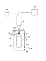
以下、図面に示す実施例により本発明を説明する。この容器殺菌装置(全体として符号1で示す)は、以下に説明する容器搬送手段によって搬送されている容器2(図2参照)に、電子線照射手段4から電子線を照射して殺菌を行うものであり、さらに、電子線照射手段4による電子線照射位置Aよりも下流側に、搬送される容器2の内部に殺菌剤を噴霧する殺菌剤噴霧手段6が設けられている。
Hereinafter, the present invention will be described with reference to embodiments shown in the drawings. This container sterilization apparatus (indicated by
この実施例では、殺菌される容器2はペットボトル等の樹脂製容器であり、図2等に示すように、ネック部2a(容器2の肩部2bよりも上方の小径の部分)の下部寄りにフランジ2cが形成されている。これら容器2は、連続して配置された複数のホイール8、10、12、14、16、18、20、22にそれぞれ設けられている容器保持手段(グリッパ)によって、前記フランジ2cの上方および下方を交互に保持されて回転搬送される。容器2は、この容器殺菌装置1の上流側に配置された図示しないエア搬送コンベヤによって連続的に搬送され、インフィードスクリュー等によって所定の間隔に切り離されて、入口チャンバー24内に設置された搬入ホイール8に受け渡される。搬入ホイール8には円周方向等間隔で複数のグリッパ(図示せず)が設けられており、容器2のフランジ2cの下側を保持してこの容器2を回転搬送する。
In this embodiment, the
入口チャンバー24に隣接して、放射線遮蔽チャンバー26が配置されており、前記搬入ホイール8によって搬送された容器2は、放射線遮蔽チャンバー26の入口側に配置された入口ホイール10に受け渡される。放射線遮蔽チャンバー26は、容器2を電子線の照射により殺菌する際に、電子線やX線(制動X線)が外部に漏れないように遮蔽する鉛製壁面から構成されている。入口ホイール10には、円周方向等間隔で複数のグリッパ(図示せず)が設けられており、前記搬入ホイール8のグリッパによってフランジ2cの下方を保持されている容器2は、この入口ホイール10のグリッパによってフランジ2cの上方を保持されて回転搬送される。放射線遮蔽チャンバー26の壁面の、搬入ホイール8から入口ホイール10への受け渡し部には、容器2が通過可能な開口部(図示せず)が形成されている。
A
放射線遮蔽チャンバー26内には、前記入口ホイール10に続いてメインホイール12が配置され、さらに出口側に出口ホイール14が配置されている。中央のメインホイール12は、図2に示すように、回転体28の外周部に円周方向等間隔で複数のグリッパ30が設けられており、前記入口ホイール10のグリッパから受け取った容器2のフランジ2cよりも下方側を保持して回転搬送する。メインホイール12のグリッパ30は、鉛直方向の回転軸32を介して取り付けられており、電子線照射手段(電子線照射装置4)が容器2に電子線を照射する照射位置Aで、容器2を180度回転させるようになっている。また、電子線照射装置4の照射窓32の前方(電子線照射位置A)を通過する容器2の背後に、ビームコレクタ34が配置されている。
In the
放射線遮蔽チャンバー26の正面側(図1の上方側)に電子線照射装置4が配置されている。電子線照射装置4は、周知のように、真空チャンバー内の真空中でフィラメントを加熱して熱電子を発生させ、高電圧によって電子を加速して高速の電子線ビームにし、照射窓32に取り付けてあるチタン(Ti)等の金属製の窓箔36を通して大気中に取り出し、前記メインホイール12のグリッパ30に保持されて前方の電子線照射位置Aに移動してきた容器2に電子線の照射を行って殺菌する。
The electron beam irradiation device 4 is arranged on the front side of the radiation shielding chamber 26 (upper side in FIG. 1). As is well known, the electron beam irradiation device 4 heats the filament in a vacuum in a vacuum chamber to generate thermoelectrons, accelerates the electrons with a high voltage to form a high-speed electron beam, and attaches to the
放射線遮蔽チャンバー26内のメインホイール12の搬送方向下流側に出口ホイール14が配置され、メインホイール12のグリッパ30によってフランジ2cの下方側を保持されて搬送されてきた容器2は、出口ホイール14のグリッパ(図示せず)によってフランジ2cの上方側を保持されて回転搬送される。
The
放射線遮蔽チャンバー26に隣接して、エアリンサ38が収容されたチャンバー40が設置されている。このチャンバー40の入口側に、中間ホイール16が配置されており、この中間ホイール16の外周部に円周方向等間隔で設けられたグリッパ(図示せず)が、前記出口ホイール14のグリッパによってフランジ2cの上方側を保持されて搬送されてきた容器2を受け取って、フランジ2cの下方側を保持して回転搬送する。放射線遮蔽チャンバー26内の出口ホイール14からエアリンサ38を収容したチャンバー40内の中間ホイール16に容器2の受け渡しを行う部分に、容器2が通過可能な開口が形成されている。
A
この中間ホイール16には、搬送されている容器2に温風を吹き付けて温度を上昇させる予備昇温手段42が設けられている。この予備昇温手段42は、無菌エア供給部44から送られたエアを加熱手段46で加熱して、中間ホイール16の周囲に配置された多数のノズル(図示せず)から、グリッパに保持されて搬送されている容器2に吹き付けるようになっている。
The
中間ホイール16に続いて、殺菌ホイール18が配置されている。殺菌ホイール18には、図3に示すように、外周部に円周方向等間隔で複数のグリッパ48が設けられており、前記中間ホイール16のグリッパによってフランジ2cの下方側を保持されて搬送されてきた容器2が、このグリッパ48に受け渡されて、容器2のフランジ2cよりも上方側が保持される。
Following the
殺菌ホイール18の外周側には、ほぼ半周に亘って、搬送される容器2の周囲を覆うカバー50が設けられている。このカバー50は、回転搬送される容器2の半径方向外方側と内方側および上方と下方を覆っている。なお、半径方向内方側の壁面50aには、殺菌ホイール18の外周部に取り付けられて回転移動するグリッパ48が通過可能な隙間52が形成されており、入口側と出口側はグリッパ48とこれに保持される容器2が通過可能な開口を除いて覆われている。カバー50の上方側の天面50bに、複数の殺菌剤噴霧手段としての噴霧管6が噴射ノズル6aを下方のカバー50内部に向けて取り付けられている。この噴霧管6には、殺菌剤供給部54と圧縮エア供給部56が接続されており、殺菌剤供給部54から噴霧管6に供給された殺菌剤の液滴が、噴霧管6内で加熱気化され、圧縮エア供給部56から供給された圧縮エアによって送られて、噴射ノズル6aからカバー50内に向けて噴射される。カバー50の半径方向外方側の壁面50cの下部寄りに排気手段58の排気管58aが設けられており、この排気管58によってカバー50内の排気を行う。なお、本実施例では、液状の殺菌剤として過酸化水素水溶液を用いているが過酢酸系の殺菌剤など他の液状殺菌剤を使用することができ、その使用形態もガス状(蒸気状)、ミスト状および噴霧、噴射等、様々な公知の形態を採用することができる。
On the outer peripheral side of the
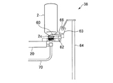
殺菌ホイール18に続いて、エアリンサ38の回転体であるリンサホイール20が配置されている。このリンサホイール20には、外周部に円周方向等間隔で複数のグリッパ60が設けられており(図4および図5参照)、殺菌ホイール18のグリッパ48によってフランジ2cの上方側を保持されて搬送されてきた容器2は、リンサホイール20のグリッパ60に受け渡されてフランジ2cの下方側を保持される。各グリッパ60は、水平な反転軸62に支持されて反転できるようになっており、半径方向外方側を向いた水平な状態と(図4に示す状態)、半径方向内方を向いた水平な状態(図5に示す状態)に180度回転することにより、保持している容器2を正立した状態と倒立した状態に反転させることができる。各グリッパ60には、溝付きのカム63が取り付けられており、このカム63が、リンサホイール20の外周側にスタンド64を介して固定設置されているカムレール66に係合しつつ移動することにより、カムレール66の軌道に応じてグリッパ60が回転する。
Following the
各グリッパ60が支持されている反転軸62の半径方向内方側に、それぞれエアノズル68が配置されている。各エアノズル68は上方を向いており、各グリッパ60が保持している容器2が倒立した状態になると、その容器2の口部内に下方から挿入される(図5に示す状態)。各エアノズル68の供給パイプ70には、前記無菌エア供給部44からエアが供給されるようになっている。また、無菌エア供給部44からエアノズル68にエアを供給する管路には、前記のように加熱手段46が接続されており、この加熱手段46を通して加熱エアを供給することができ、また、エアを加熱せずに容器2内に供給することもできるようになっている。
エアリンサ38によってリンスが行われた容器2は、エアリンサ用チャンバー40に隣接して配置された出口チャンバー74内に設置された搬出ホイール22に引き渡される。搬出ホイール22には、外周部に円周方向等間隔で複数のグリッパ(図示せず)が設けられており、リンサホイール20のグリッパ60によってフランジ2cの下方を保持されて搬送されてきた容器2は、搬出ホイール22のグリッパに受け渡されて、フランジ2cよりも上方を保持される。搬出ホイール22によって回転搬送された容器2は、この容器殺菌装置1から排出されて充填やキャッピング等の次の工程に送られる。エアリンサ用チャンバー40と出口チャンバー74との境の壁面には、容器2が通過可能な開口が形成されている。
The
この実施例に係る容器殺菌装置1は、制御手段76によってその作動を制御されるようになっている。特に、容器搬送手段(この実施例では、入口ホイール10からリンサホイール20までの各ホイールを容器搬送手段と呼ぶ)によって搬送されている容器2に電子線照射装置4から電子線を照射して殺菌を行った後、殺菌ホイール18において容器2内に殺菌剤を噴霧して殺菌を行う第1殺菌モードと、電子線照射装置4による殺菌だけを行う第2殺菌モードとに切り換えできるようになっている。制御手段76には、この第1殺菌モードと第2殺菌モードを登録する記憶部78が設けられており、この登録された殺菌モードに応じて制御部80が制御を行う。
The operation of the
以上の構成にかかる容器殺菌装置1の作動について説明する。この実施例に係る容器殺菌装置1は、電子線照射装置4により電子線を容器2に照射して殺菌を行った後、殺菌剤噴霧手段(噴霧管)6で容器2内に殺菌剤を噴霧して殺菌を行う第1殺菌モードと、電子線照射装置4による殺菌だけを行う第2殺菌モードに切り替え可能になっており、まず、第1殺菌モードで殺菌を行う場合について説明する。
Operation | movement of the
図示しないエア搬送コンベヤによって連続的に搬送されてきた容器2は、インフィードスクリュー等によって所定の間隔に切り離された後、入口チャンバー24内に設置された搬入ホイール8のグリッパに引き渡される。搬入ホイール8のグリッパによって回転搬送された容器2は、放射線遮蔽チャンバー26の入口側に配置された入口ホイール10に引き渡される。入口ホイール10のグリッパによって保持されて回転搬送された容器2は、メインホイール12のグリッパ30に引き渡されてフランジ2cの下方側を保持される。メインホイール12のグリッパ30に保持されて回転搬送され、電子線照射位置Aに移動してきた容器2に対し、電子線照射装置4から電子線が照射されて殺菌が行われる。このときグリッパ30が180度回転(鉛直方向の軸線を中心に180度回転)されて容器2の全周に電子線が照射され外面全体が殺菌される。
The
電子線による殺菌が終了した容器2は、メインホイール12から出口ホイール14に引き渡され、さらに、隣接するチャンバー40の入口側に設置された中間ホイール16に引き渡される。中間ホイール16には、ほぼ半周に亘って予備昇温手段42が設けられており、この中間ホイール16で回転搬送されている間に、図示しない多数のノズルから温風が吹き付けられて容器2が昇温される。このように容器2の内部を予め昇温しておくことにより、この後に噴霧される殺菌剤が急激に凝縮することなく満遍なく付着し、高い殺菌効果を発揮することができる。
The
その後、容器2は、中間ホイール16のグリッパから殺菌ホイール18のグリッパ48に受け渡され、殺菌ホイール18によって回転搬送される。殺菌ホイール18のグリッパ48が移動する経路の周囲に、殺菌ホイール18のほぼ半周に亘るカバー50が設けられており、グリッパ48に保持された容器2は、このカバー50の内部を搬送される。カバー50の天面50bには、殺菌剤噴霧手段としての噴霧管6が、噴射ノズル6aを下方へ向けて等間隔で複数設けられており、これら噴霧管6内で加熱気化された殺菌剤が噴射ノズル6aから容器2の内部に向けて噴射される。容器2の内部に噴射され殺菌剤や、容器2外に噴射された殺菌剤は、カバー50の内部に充満し、排気管58aから排気される。これにより、噴霧された殺菌剤を含んだ雰囲気が次工程や前工程に流れることがなく、特に、電子線照射位置Aまで流れて窓箔36を腐食させたり、電子線の照射に伴って発生する窒素酸化物と反応して硝酸を生じさせ、装置の金属部分を腐食させることがない。容器2が、肉厚の厚い樹脂ボトル等の場合には、電子線照射装置46から照射された電子線が容器2の内部まで届きにくく、充分な殺菌ができない場合があるが、電子線照射装置4による殺菌の後、さらに、殺菌剤噴霧手段(噴霧管6)から気化した殺菌剤を容器2の内部側に噴射して殺菌を行うので、この第1殺菌モードによって容器2を完全に殺菌することができる。特に、従来の電子線照射装置による電子線殺菌では、ネック部2aを除く胴体部分の厚さが概ね0.4mmを超える比較的肉厚の厚い容器2については、電子線が透過しにくく内部まで十分に電子線が届かないため、必要な殺菌効果を得られない場合があったが、殺菌剤による殺菌を併用することにより十分な殺菌効果を得ることができる。
Thereafter, the
殺菌ホイール18で搬送されている間に、殺菌剤による殺菌が行われた容器2は、殺菌ホイール18のグリッパ48から次のエアリンサ38のリンサホイール20に設けられているグリッパ60に受け渡される。エアリンサ38のグリッパ60は、殺菌ホイール18から容器2を受け取る時点では、図4に示すように、カム63の溝が下方に配置されているカムレール66に係合しており、グリッパ60は、リンサホイール20の半径方向外方側を向いた水平状態であり、容器2を直立した状態でそのフランジ2cの下方側を保持する。その後、グリッパ60が回転移動していくと、カム63がカムレール66の軌道に沿って移動して、グリッパ60をリンサホイール20の半径方向内方側へ反転させる。グリッパ60がリンサホイール20の半径方向内方側を向いた水平状態になると、容器2が反転軸62を中心に180度回転して倒立状態になり、エアノズル68が容器2の口部内に挿入された状態になる(図5参照)。
The
エアリンサ38ではエアノズル68から無菌エアを容器2内に噴射して、容器2の内部の異物等を排出する。さらに、第1殺菌モードで電子線照射装置4による殺菌の後、殺菌剤噴霧手段(噴霧管6)による殺菌も行った場合には、無菌エア供給部44から供給されたエアを加熱手段46によって加熱したエアを噴射するので、加熱エアにより容器2内を加熱して付着している殺菌剤成分の分解を促進させ、残留を防ぐ作用も行うことができる。エアリンサ38によりリンスを行った後、容器2は、出口チャンバー74内に設置されている搬出ホイール22に引き渡され、この容器殺菌装置1から排出されて次の工程に送られる。
In the
また、ネック部2aを除く胴体部分の厚さが概ね0.4mm以下の比較的肉厚の薄い容器2については、電子線照射装置4のみで容器2の殺菌を行う第2殺菌モードで殺菌を実施する。電子線照射装置4のみで容器2の殺菌を行う第2殺菌モードの場合には、前記第1殺菌モードの場合と同様に、メインホイール12により搬送している容器2に電子線照射装置4から電子線を照射して殺菌を行った後、出口ホイール14、中間ホイール16および殺菌ホイール18に容器2を順次受け渡す。この殺菌ホイール18では、殺菌剤供給部44および圧縮エア供給部56を作動させず、グリッパ48に保持されている容器2を単に回転搬送し、次のエアリンサ38に受け渡す。エアリンサ38では、グリッパ60が直立した状態で容器2を受け取り、この容器2を搬送しつつ倒立させ、容器2の内部に下方からエアノズル68が挿入された状態にする。第2殺菌モードでは、この状態でエアノズル68から、加熱手段46による加熱をしていないエアを噴射し、容器2内の異物を排出させる。このように、容器2の厚さが全体的に薄い場合には、必要以上に加熱しないようにすることで収縮や変形することを防止している。なお、エアリンサ38の形態としては、容器2を倒立状態で処理するものに限らず、容器2を口部を上方に向けた直立状態のまま搬送し、容器2の上方に配置したエアノズル68から容器2内に向けて、加熱手段46で加熱された加熱エアもしくは加熱をしていない無菌エアを噴射するよう構成したものであってもよい。このように、第2殺菌モードにおいては、容器2の肉厚の厚さが全体的に薄い容器に対して、容器2の殺菌効果を得つつ、容器2の熱収縮や変形を防止することが可能である。
In addition, the relatively
2 容器
4 電子線照射手段(電子線照射装置)
6 殺菌剤噴霧手段(噴霧管)
10 入口ホイール(容器搬送手段)
12 メインホイール(容器搬送手段)
14 出口ホイール(容器搬送手段)
16 中間ホイール(容器搬送手段)
18 殺菌ホイール(容器搬送手段)
20 リンサホイール(容器搬送手段)
2 Container 4 Electron beam irradiation means (electron beam irradiation device)
6 Disinfectant spray means (spray tube)
10 Entrance wheel (container transport means)
12 Main wheel (container transport means)
14 Exit wheel (container transport means)
16 Intermediate wheel (container transport means)
18 Sterilization wheel (container transport means)
20 Rinser wheel (container transport means)
Claims (4)
前記容器搬送手段の電子線照射位置よりも搬送方向下流側に配置され、搬送される容器の内部に殺菌剤を噴霧する殺菌剤噴霧手段と、前記容器殺菌装置の作動を制御する制御手段を備えるとともに、
前記制御手段は、前記電子線照射手段と前記殺菌剤噴霧手段により容器を殺菌する第1殺菌モードと、電子線照射手段のみで容器を殺菌する第2殺菌モードとを備えていることを特徴とする容器殺菌装置。 In a container sterilization apparatus comprising a container transport means for transporting a container and an electron beam irradiation means for irradiating an electron beam to the transported container,
A disinfectant spraying means for spraying a disinfectant inside the container to be transported disposed downstream of the electron beam irradiation position of the container transporting means, and a control means for controlling the operation of the container disinfection device. With
The control means includes a first sterilization mode in which the container is sterilized by the electron beam irradiation means and the sterilizing agent spraying means, and a second sterilization mode in which the container is sterilized only by the electron beam irradiation means. Container sterilization device.
前記第1殺菌モードでは、前記加熱手段で加熱して前記気体供給手段から容器の内部に無菌気体を供給し、前記第2殺菌モードでは、前記加熱手段で加熱せずに前記気体供給手段から容器の内部に無菌気体を供給することを特徴とする請求項1または請求項2に記載の容器殺菌装置。 A gas supply means that is disposed downstream of the disinfectant spraying position of the disinfectant spraying means and supplies a sterile gas to the inside of the container to be transported, and a heating means for heating the gas supplied by the gas supply means It equipped with a door,
In the first sterilization mode, aseptic gas is supplied into the container from the gas supply means by heating with the heating means, and in the second sterilization mode, the container is supplied from the gas supply means without being heated by the heating means. The container sterilizer according to claim 1 or 2 , wherein aseptic gas is supplied to the inside of the container.
容器の肉厚により前記第1殺菌モードと前記第2殺菌モードとを切り換えることを特徴とする容器殺菌方法。 A first sterilization mode of spraying a sterilizing agent inside the container after irradiating an electron beam on the outer surface of the container to be transported, and then supplying a heated aseptic gas to the inside of the container to remove sterilizing components ; A second sterilization mode for discharging a foreign gas in the container by supplying an unheated aseptic gas to the inside of the container after irradiating the outer surface of the container to be transported with an electron beam;
A container sterilization method, wherein the first sterilization mode and the second sterilization mode are switched depending on the thickness of the container.
Priority Applications (1)
| Application Number | Priority Date | Filing Date | Title |
|---|---|---|---|
| JP2014100704A JP6310768B2 (en) | 2014-05-14 | 2014-05-14 | Container sterilizer |
Applications Claiming Priority (1)
| Application Number | Priority Date | Filing Date | Title |
|---|---|---|---|
| JP2014100704A JP6310768B2 (en) | 2014-05-14 | 2014-05-14 | Container sterilizer |
Publications (3)
| Publication Number | Publication Date |
|---|---|
| JP2015217951A JP2015217951A (en) | 2015-12-07 |
| JP2015217951A5 JP2015217951A5 (en) | 2017-01-19 |
| JP6310768B2 true JP6310768B2 (en) | 2018-04-11 |
Family
ID=54777671
Family Applications (1)
| Application Number | Title | Priority Date | Filing Date |
|---|---|---|---|
| JP2014100704A Active JP6310768B2 (en) | 2014-05-14 | 2014-05-14 | Container sterilizer |
Country Status (1)
| Country | Link |
|---|---|
| JP (1) | JP6310768B2 (en) |
Families Citing this family (3)
| Publication number | Priority date | Publication date | Assignee | Title |
|---|---|---|---|---|
| EP3466821B1 (en) | 2016-05-31 | 2022-11-09 | Dai Nippon Printing Co., Ltd. | Cap sterilization apparatus, content loading system, cap sterilization method |
| JP6394644B2 (en) * | 2016-06-17 | 2018-09-26 | 大日本印刷株式会社 | Cap sterilizer and contents filling system |
| WO2020075846A1 (en) | 2018-10-11 | 2020-04-16 | サントリーホールディングス株式会社 | Sterilization device and sterilization method |
Family Cites Families (5)
| Publication number | Priority date | Publication date | Assignee | Title |
|---|---|---|---|---|
| JP2003237742A (en) * | 2002-02-13 | 2003-08-27 | Toppan Printing Co Ltd | Method of aseptically filling pouch having spout |
| JP4617901B2 (en) * | 2005-01-31 | 2011-01-26 | 凸版印刷株式会社 | Sterilization filling method of pouch with two-neck closure |
| BRPI0712797A2 (en) * | 2006-06-02 | 2012-10-02 | Tetra Laval Holdings & Finance | method for stellar packaging material |
| DE102009041215A1 (en) * | 2009-09-11 | 2011-03-24 | Krones Ag | Method and apparatus for stretch blow molding or blow molding and filling sterile containers |
| JP2013018535A (en) * | 2011-07-14 | 2013-01-31 | Toppan Printing Co Ltd | Method of sterilizing paper container for liquid and paper container for liquid using the method and sterilizer |
-
2014
- 2014-05-14 JP JP2014100704A patent/JP6310768B2/en active Active
Also Published As
| Publication number | Publication date |
|---|---|
| JP2015217951A (en) | 2015-12-07 |
Similar Documents
| Publication | Publication Date | Title |
|---|---|---|
| JP5141185B2 (en) | Container sterilizer | |
| KR101390759B1 (en) | Container filling system | |
| JP4946431B2 (en) | Container sterilizer | |
| EP1748951B1 (en) | Apparatus and method for sterilising bottles and/or caps and filling them | |
| KR100843572B1 (en) | Apparatus and method for sterilization of vessels | |
| JP2011056943A (en) | Method and apparatus for producing sterile container by stretch blow molding or blow molding and using molded container for filling | |
| CN105682886B (en) | Blow molding device | |
| WO2018056411A1 (en) | Aseptic filling machine, and aseptic filling method | |
| JP6310768B2 (en) | Container sterilizer | |
| US20190337786A1 (en) | Cap sterilizer, content filling system, cap sterilization method, and content filling method | |
| WO2020179521A1 (en) | Container sterilization device, content filling system, container sterilization method, and content filling method | |
| JP6551803B2 (en) | Cap sterilizer, content filling system, cap sterilizing method and content filling method | |
| CN110475723B (en) | Aseptic filling method and aseptic filling machine | |
| JP2020019567A (en) | Filling system and filling method | |
| JP6330876B2 (en) | Aseptic filling machine and aseptic filling method | |
| JP6521141B2 (en) | Aseptic filling machine and aseptic filling method | |
| JP5045140B2 (en) | Electron beam sterilization system | |
| JP6886642B2 (en) | Cap sterilizer, content filling system, cap sterilization method and content filling method | |
| JP6886643B2 (en) | Cap sterilizer, content filling system, cap sterilization method and content filling method | |
| JP6788848B2 (en) | Cap sterilizer, content filling system, cap sterilization method and content filling method | |
| JP6886644B2 (en) | Cap sterilizer, content filling system, cap sterilization method and content filling method | |
| JP6516113B2 (en) | Aseptic filling machine and aseptic filling method | |
| JP7193700B2 (en) | Filling system and filling method | |
| WO2020009010A1 (en) | Filling system and filling method |
Legal Events
| Date | Code | Title | Description |
|---|---|---|---|
| A521 | Request for written amendment filed |
Free format text: JAPANESE INTERMEDIATE CODE: A523 Effective date: 20161202 |
|
| A621 | Written request for application examination |
Free format text: JAPANESE INTERMEDIATE CODE: A621 Effective date: 20161202 |
|
| A977 | Report on retrieval |
Free format text: JAPANESE INTERMEDIATE CODE: A971007 Effective date: 20171020 |
|
| A711 | Notification of change in applicant |
Free format text: JAPANESE INTERMEDIATE CODE: A711 Effective date: 20171026 |
|
| A131 | Notification of reasons for refusal |
Free format text: JAPANESE INTERMEDIATE CODE: A131 Effective date: 20171031 |
|
| A521 | Request for written amendment filed |
Free format text: JAPANESE INTERMEDIATE CODE: A821 Effective date: 20171026 |
|
| A521 | Request for written amendment filed |
Free format text: JAPANESE INTERMEDIATE CODE: A523 Effective date: 20171227 |
|
| TRDD | Decision of grant or rejection written | ||
| A01 | Written decision to grant a patent or to grant a registration (utility model) |
Free format text: JAPANESE INTERMEDIATE CODE: A01 Effective date: 20180313 |
|
| A61 | First payment of annual fees (during grant procedure) |
Free format text: JAPANESE INTERMEDIATE CODE: A61 Effective date: 20180319 |
|
| R150 | Certificate of patent or registration of utility model |
Ref document number: 6310768 Country of ref document: JP Free format text: JAPANESE INTERMEDIATE CODE: R150 |
|
| R250 | Receipt of annual fees |
Free format text: JAPANESE INTERMEDIATE CODE: R250 |
|
| R250 | Receipt of annual fees |
Free format text: JAPANESE INTERMEDIATE CODE: R250 |
|
| R250 | Receipt of annual fees |
Free format text: JAPANESE INTERMEDIATE CODE: R250 |
|
| R250 | Receipt of annual fees |
Free format text: JAPANESE INTERMEDIATE CODE: R250 |