JP6309817B2 - Work vehicle - Google Patents
Work vehicle Download PDFInfo
- Publication number
- JP6309817B2 JP6309817B2 JP2014100742A JP2014100742A JP6309817B2 JP 6309817 B2 JP6309817 B2 JP 6309817B2 JP 2014100742 A JP2014100742 A JP 2014100742A JP 2014100742 A JP2014100742 A JP 2014100742A JP 6309817 B2 JP6309817 B2 JP 6309817B2
- Authority
- JP
- Japan
- Prior art keywords
- arm
- detent
- raising
- lowering
- detent mechanism
- Prior art date
- Legal status (The legal status is an assumption and is not a legal conclusion. Google has not performed a legal analysis and makes no representation as to the accuracy of the status listed.)
- Active
Links
Images


Classifications
-
- E—FIXED CONSTRUCTIONS
- E02—HYDRAULIC ENGINEERING; FOUNDATIONS; SOIL SHIFTING
- E02F—DREDGING; SOIL-SHIFTING
- E02F9/00—Component parts of dredgers or soil-shifting machines, not restricted to one of the kinds covered by groups E02F3/00 - E02F7/00
- E02F9/20—Drives; Control devices
- E02F9/2004—Control mechanisms, e.g. control levers
-
- E—FIXED CONSTRUCTIONS
- E02—HYDRAULIC ENGINEERING; FOUNDATIONS; SOIL SHIFTING
- E02F—DREDGING; SOIL-SHIFTING
- E02F3/00—Dredgers; Soil-shifting machines
- E02F3/04—Dredgers; Soil-shifting machines mechanically-driven
- E02F3/28—Dredgers; Soil-shifting machines mechanically-driven with digging tools mounted on a dipper- or bucket-arm, i.e. there is either one arm or a pair of arms, e.g. dippers, buckets
- E02F3/36—Component parts
- E02F3/42—Drives for dippers, buckets, dipper-arms or bucket-arms
- E02F3/43—Control of dipper or bucket position; Control of sequence of drive operations
-
- E—FIXED CONSTRUCTIONS
- E02—HYDRAULIC ENGINEERING; FOUNDATIONS; SOIL SHIFTING
- E02F—DREDGING; SOIL-SHIFTING
- E02F3/00—Dredgers; Soil-shifting machines
- E02F3/04—Dredgers; Soil-shifting machines mechanically-driven
- E02F3/28—Dredgers; Soil-shifting machines mechanically-driven with digging tools mounted on a dipper- or bucket-arm, i.e. there is either one arm or a pair of arms, e.g. dippers, buckets
- E02F3/34—Dredgers; Soil-shifting machines mechanically-driven with digging tools mounted on a dipper- or bucket-arm, i.e. there is either one arm or a pair of arms, e.g. dippers, buckets with bucket-arms, i.e. a pair of arms, e.g. manufacturing processes, form, geometry, material of bucket-arms directly pivoted on the frames of tractors or self-propelled machines
-
- E—FIXED CONSTRUCTIONS
- E02—HYDRAULIC ENGINEERING; FOUNDATIONS; SOIL SHIFTING
- E02F—DREDGING; SOIL-SHIFTING
- E02F3/00—Dredgers; Soil-shifting machines
- E02F3/04—Dredgers; Soil-shifting machines mechanically-driven
- E02F3/28—Dredgers; Soil-shifting machines mechanically-driven with digging tools mounted on a dipper- or bucket-arm, i.e. there is either one arm or a pair of arms, e.g. dippers, buckets
- E02F3/36—Component parts
- E02F3/42—Drives for dippers, buckets, dipper-arms or bucket-arms
- E02F3/427—Drives for dippers, buckets, dipper-arms or bucket-arms with mechanical drives
-
- E—FIXED CONSTRUCTIONS
- E02—HYDRAULIC ENGINEERING; FOUNDATIONS; SOIL SHIFTING
- E02F—DREDGING; SOIL-SHIFTING
- E02F3/00—Dredgers; Soil-shifting machines
- E02F3/04—Dredgers; Soil-shifting machines mechanically-driven
- E02F3/28—Dredgers; Soil-shifting machines mechanically-driven with digging tools mounted on a dipper- or bucket-arm, i.e. there is either one arm or a pair of arms, e.g. dippers, buckets
- E02F3/36—Component parts
- E02F3/42—Drives for dippers, buckets, dipper-arms or bucket-arms
- E02F3/43—Control of dipper or bucket position; Control of sequence of drive operations
- E02F3/431—Control of dipper or bucket position; Control of sequence of drive operations for bucket-arms, front-end loaders, dumpers or the like
-
- E—FIXED CONSTRUCTIONS
- E02—HYDRAULIC ENGINEERING; FOUNDATIONS; SOIL SHIFTING
- E02F—DREDGING; SOIL-SHIFTING
- E02F9/00—Component parts of dredgers or soil-shifting machines, not restricted to one of the kinds covered by groups E02F3/00 - E02F7/00
- E02F9/20—Drives; Control devices
- E02F9/2004—Control mechanisms, e.g. control levers
- E02F9/2012—Setting the functions of the control levers, e.g. changing assigned functions among operations levers, setting functions dependent on the operator or seat orientation
Description
本発明は、デテント機能を有する操作レバーを備えた作業車両に関する。 The present invention relates to a work vehicle including an operation lever having a detent function.
特許文献1に記載された作業車両は、リフトアームの上げ下げを操作する操作レバーを所定の操作位置(上げ操作端位置および下げ操作端位置)に操作すると、その操作位置に操作レバーを保持するデテント機能を備えている。このようなデテント機能を備えることで、例えば、リフトアームを上げた状態で走行する場合に、上げ操作端位置にデテントさせる(保持させる)ことで、必ずしもリフトアーム上げ操作と走行操作とを両方同時に行う必要がなく、走行操作に専念することができる。
The work vehicle described in
ところで、操作レバーを上げ操作端位置にデテントさせた場合、リフトアームの角度が所定の上限角度を超えると自動的にデテント機能が解除される。操作レバーには、操作レバーを中立位置に保持するためのバネ等が設けられており、上げ操作端位置のデテントが解除されると、操作レバーがバネ等の力によって中立位置方向に戻される。 By the way, when the operating lever is raised and detented to the operating end position, the detent function is automatically canceled when the angle of the lift arm exceeds a predetermined upper limit angle. The operation lever is provided with a spring or the like for holding the operation lever in the neutral position, and when the detent at the raising operation end position is released, the operation lever is returned to the neutral position direction by the force of the spring or the like.
しかしながら、操作レバーが中立位置で停止せずに反対側の操作端(下げ操作端位置)付近まで移動することがある。そのような場合、下げ側のデテント機能によって操作レバーが下げ操作端位置にデテントされ、オペレータの意図とは逆のリフトアーム下げ動作となってしまう。そのため、オペレータに違和感を与えてしまい、作業車両の操作性が損なわれてしまう。 However, the operation lever may move to the vicinity of the opposite operation end (lower operation end position) without stopping at the neutral position. In such a case, the operation lever is detented to the lower operation end position by the detent function on the lower side, and the lift arm lowering operation opposite to the operator's intention is performed. Therefore, the operator feels uncomfortable and the operability of the work vehicle is impaired.
請求項1に係る作業車両は、作業車両の車両本体の前部に、上下方向に回動可能に連結されたリフトアームと、上げ操作端位置と下げ操作端位置との間で操作可能であって、前記リフトアームの上げ下げを操作する操作レバーと、前記上げ操作端位置に操作された前記操作レバーを、該上げ操作端位置に保持する保持機能を有する上げデテント機構と、前記下げ操作端位置に操作された前記操作レバーを、該下げ操作端位置に保持する保持機能を有する下げデテント機構と、を備え、前記リフトアームの角度が所定上限を超えると、前記上げデテント機構の保持機能および前記下げデテント機構の保持機能が解除され、前記上げデテント機構は、前記操作レバーを磁力により前記上げ操作端位置に保持する上げデテントコイルを有し、前記下げデテント機構は、前記操作レバーを磁力により前記下げ操作端位置に保持する下げデテントコイルを有し、前記リフトアームの角度が前記所定上限を下回っている場合には前記上げデテントコイルおよび前記下げデテントコイルを通電状態とし、前記リフトアームの角度が前記所定上限を超えると前記上げデテントコイルおよび前記下げデテントコイルの通電を遮断するデテント制御回路を備えることを特徴とする。
請求項2の発明は、請求項1に記載の作業車両において、前記リフトアームの角度を検出するアーム角度センサと、前記アーム角度センサで検出された角度が所定上限を超えると、前記上げデテント機構の保持機能および前記下げデテント機構の保持機能を第1の所定時間だけ解除し、前記第1の所定時間が経過した後に前記下げデテント機構の保持機能を再び動作させる制御部と、を備えることを特徴とする。
請求項3の発明は、請求項2に記載の作業車両において、前記制御部は、前記アーム角度センサで検出された角度が所定下限を下回ると、前記上げデテント機構の保持機能および前記下げデテント機構の保持機能を第2の所定時間だけ解除し、前記第2の所定時間が経過した後に前記上げデテント機構の保持機能を再び動作させることを特徴とする。
請求項4の発明は、請求項1に記載の作業車両において、前記デテント制御回路は、前記所定上限を下回っているとオンし、前記所定上限を超えるとオフするスイッチと、前記スイッチのオンオフに連動して前記上げデテントコイルおよび前記下げデテントコイルの通電を制御するリレーと、を備えることを特徴とする。
The work vehicle according to
According to a second aspect of the present invention, in the work vehicle according to the first aspect, an arm angle sensor that detects an angle of the lift arm, and the lifting detent mechanism when the angle detected by the arm angle sensor exceeds a predetermined upper limit. And a control unit that releases the holding function of the lowering detent mechanism for a first predetermined time and operates the holding function of the lowering detent mechanism again after the first predetermined time has elapsed. Features.
According to a third aspect of the present invention, in the work vehicle according to the second aspect, when the angle detected by the arm angle sensor falls below a predetermined lower limit, the control unit holds the lifting detent mechanism and the lowering detent mechanism. The holding function is canceled for a second predetermined time, and the holding function of the raising detent mechanism is operated again after the second predetermined time has elapsed.
The invention according to claim 4, in the working vehicle according to
本発明によれば、作業車両の操作性向上を図ることができる。 According to the present invention, it is possible to improve the operability of the work vehicle.
以下、図を参照して本発明を実施するための形態について説明する。図1は、本発明に係る作業車両の一実施の形態を示す図であり、ホイールローダの側面図である。ホイールローダ100は、リフトアーム111、バケット112、タイヤ113等を有する前部車体110と、運転室121、エンジン室122、タイヤ123等を有する後部車体120とを備えている。
Hereinafter, embodiments for carrying out the present invention will be described with reference to the drawings. FIG. 1 is a diagram showing an embodiment of a work vehicle according to the present invention, and is a side view of a wheel loader. The
リフトアーム(以下、単にアームと呼ぶ)111は前部車体110に対して上下方向に回動可能に取り付けられ、アームシリンダ114の駆動により回動駆動される。バケット112はアーム111の先端において、アーム111に対して前後傾方向(上下方向)に回動可能に取り付けられ、バケットシリンダ115の駆動により回動駆動される。前部車体110と後部車体120はセンタピン101により互いに回動自在に連結され、ステアリングシリンダ(不図示)の伸縮により後部車体120に対し前部車体110が左右に屈
折する。
A lift arm (hereinafter simply referred to as an arm) 111 is attached to the
アーム111の回動部には、アーム111の前部車体110に対する回動角度を検出するアーム角度センサ56が設けられ、バケットシリンダ115には、バケット112のアーム111に対する回動角度を表すバケットシリンダ115のストローク量を検出するストローク量検出装置58が設けられている。
An
図2はホイールローダ100の運転室121内に配置される操作部材を示す模式図である。運転室121には、運転者がホイールローダ100を操舵するためのステアリングホイール191と、アクセルペダル192と、左右で連動する一対のブレーキペダル193と、アーム111を上方向あるいは下方向に回動させるためのアーム操作レバー141と、バケット112を後傾方向(上方向)あるいは前傾方向(下方向)に回動させるためのバケット操作レバー142とが配設されている。バケット112が後傾方向に回動されることをバケット112がチルトされる、とも言う。バケット112が前傾方向に回動されることをバケット112がダンプされる、とも言う。
FIG. 2 is a schematic diagram showing an operation member arranged in the
本願発明に係る作業車両は、アーム操作レバー141のデテント機能に特徴を有している。まず、図3を用いて、アーム111を上方向あるいは下方向に回動させるための油圧回路について説明する。図3は、ホイールローダ100の作業用油圧回路を示す図であり、アーム111に関する油圧回路と、バケット112に関する油圧回路とを含む。
The work vehicle according to the present invention is characterized by the detent function of the
図3の油圧回路には、メインポンプ6からアームシリンダ114に供給される圧油の方向と流量を制御してアームシリンダ114の駆動を制御するアーム用コントロールバルブ41と、メインポンプ6から不図示のバケットシリンダに供給される圧油の方向と流量を制御してバケットシリンダの駆動を制御するバケット用コントロールバルブ42とが設けられている。アーム用コントロールバルブ41の動作は、パイロットバルブ14に設けられたアーム操作レバー141を操作することによって制御される。バケット用コントロールバルブ42の動作は、パイロットバルブ14に設けられたバケット操作レバー142を操作することによって制御される。
3 includes an
以下では、アーム111に関する油圧回路について説明する。パイロットバルブ14は、パイロットポンプ46から吐出される圧油をアーム操作レバー141の操作量に応じたパイロット圧の圧油とし、それをアーム用コントロールバルブ41に供給する。アーム用コントロールバルブ41は、パイロット圧(アーム上げパイロット圧力およびアーム下げパイロット圧力)に応じてスプールのストローク量を変更して、アームシリンダ114に供給される圧油の方向および流量を制御する制御バルブである。
Hereinafter, a hydraulic circuit related to the
図3に示すようにアーム操作レバー141が中立位置とされると、アーム用コントロールバルブ41は図3に示す中立位置に制御される。図3の状態からアーム操作レバー141を上げ操作端位置(U)側に操作すると、アーム用コントロールバルブ41は中立位置からアーム上昇位置(Uv)に向かって切り換わる。その結果、アームシリンダ114のシリンダロッドが伸長されて、図1に示すアーム111が上方向に回動駆動される。
As shown in FIG. 3, when the
図3の状態からアーム操作レバー141を下げ操作端位置(F)側(中立位置と下げ操作端位置(F)との間の位置)に操作すると、アーム用コントロールバルブ41は中立位置からアーム下降位置(Dv)に向かって切り換わる。その結果、アームシリンダ114のシリンダロッドが縮退されて、アーム111が下方向に回動駆動される。
When the
図3の状態からアーム操作レバー141を下げ操作端位置(F)に操作すると、アーム用コントロールバルブ41はフロート位置(Fv)に切り換わる。その結果、アーム111は自由落下して、バケット112が地上に接すると外力のまま自由に上下動するようになる。
When the
図3に示すように、アーム操作レバー141は、アーム操作レバー141を所定の操作位置で保持するためのデテント機構141a,141bを備えている。デテント機構には様々な構造のものがあるが、本実施の形態のデテント機構141a,141bでは、図4に示すように、電磁石の磁力によってアーム操作レバー141を吸着保持するようにしている。C1,C2はデテント機構141a,141bの電磁石のソレノイドコイルであり、本実施の形態ではデテントコイルC1,C2と呼ぶことにする。
As shown in FIG. 3, the
図4に示すように、アーム操作レバー141には、アーム操作レバー141を中立位置に保つためのバネ144a,144bが設けられており、アーム111の上下動作を行わない停止状態の場合には、図4(b)に示すような中立位置とされている。
As shown in FIG. 4, the
デテント機構141a,141bに設けられたデテントコイルC1,C2には電流が通電されており、図4(a)のようにアーム操作レバー141が中立位置から上げ操作端位置(U)またはその近傍位置まで操作されると、被吸引部143aがデテント機構141aの電磁石に吸引保持され、アーム操作レバー141が上げ操作端位置(U)に保持される。その結果、アーム用コントロールバルブ41がアーム上昇位置(Uv)で保持され、アーム操作レバー141を離してもアーム111は上方向に回動駆動される。
The detent coils C1 and C2 provided in the
このとき、アーム操作レバー141には、パイロット1次圧および2次圧による油圧反力F1と、バネ144aの反発力F2およびデテント機構141aによる電磁吸引力F3が作用しており、F3>F1+F2のように磁力が設定されているため、アーム操作レバー141が上げ操作端位置(U)に保持される。
At this time, a hydraulic reaction force F1 due to the pilot primary pressure and the secondary pressure, a repulsive force F2 of the
一方、図4(c)のようにアーム操作レバー141が中立位置から下げ操作端位置(D)またはその近傍位置まで操作されると、被吸引部143bがデテント機構141bの電磁石に吸引保持され、アーム操作レバー141が下げ操作端位置(F)に保持される。アーム操作レバー141が下げ操作端位置(F)に保持されると、アーム用コントロールバルブ41はフロート位置(Fv)に切り換えられ、その状態に保持される。その結果、アーム111は自由落下して、バケット112が地上に接すると外力のまま自由に上下動するようになる。この場合も、アーム操作レバー141には、パイロット圧による油圧反力F1と、バネ144bの反発力F2およびデテント機構141bによる電磁吸引力F3が作用しており、F3>F1+F2のように磁力が設定されている。
On the other hand, as shown in FIG. 4C, when the
デテント機構141aによる電磁保持は、アーム111が所定上限高さを超えると、すなわちアーム角度が所定上限値を超えると解除される。また、デテント機構141bによる電磁保持は、アーム111が下降して所定下限高さを下回ると、すなわちアーム角度が所定下限値を下回ると解除される。
The electromagnetic holding by the
アーム操作レバー141が電磁保持されている状態でデテントコイルC1またはデテントコイルC2への通電が断たれると、電磁吸引力F3がゼロとなってデテント機構141a,141bによる電磁保持が解除され、アーム操作レバー141は力(F1+F2)によって中立位置に戻される。アーム操作レバー141が中立位置となると、アーム用コントロールバルブ41は中立位置(Nv)に切り換えられ、アーム111の回動が停止する。
If power to the detent coil C1 or the detent coil C2 is cut off while the
ところで、前述したように、操作レバー141,142の先端は握り等が設けられているため比較的質量が大きく、デテントコイルC1,C2の通電を停止したときに、慣性のために操作レバー141,142が中立位置で停止せずに反対側の操作端位置付近まで移動することがある。 By the way, as described above, the tips of the operation levers 141 and 142 are provided with grips and the like, so that the mass is relatively large. When the energization of the detent coils C1 and C2 is stopped, the operation levers 141 and 142 may move to near the operation end position on the opposite side without stopping at the neutral position.
例えば、図4(a)に示すようにアーム操作レバー141が上げ操作端位置(U)に保持されている場合に、デテントコイルC1の通電を停止して保持が解除されると、アーム操作レバー141が中立位置を越えて下げ操作端位置(F)付近まで移動する。このときデテントコイルC2は通電されているので、被吸引部143bがデテントコイルC2の磁力より吸引保持されてしまう。その結果、アーム用コントロールバルブ41がフロート位置(Fv)に切り換えられ、アーム111が自由落下することになる。
For example, when the
そこで、本実施の形態では、コントロールユニット10によるデテントコイルC1,C2の通電制御を以下に説明するような制御とすることにより、デテント機能が解除された際に、アーム操作レバー141が反対側の操作端位置に保持されてしまうのを防止するようにした。
Therefore, in the present embodiment, the energization control of the detent coils C1 and C2 by the
図5は、デテントコイルC1,C2の通電制御に関する制御系のブロック図である。ホイールローダ100のコントロールユニット10には、アーム角度センサ56からの信号が入力されている。コントロールユニット10は、アーム角度センサ56からの信号に基づいてデテントコイルC1,C2の通電を制御する。アーム111の角度が所定上限値と所定下限値との間にある場合には、コントロールユニット10はデテントコイルC1,C2を通電させる。
FIG. 5 is a block diagram of a control system related to energization control of the detent coils C1 and C2. A signal from the
そして、アーム角度が所定上限値を超えた場合、および、アーム角度が所定下限値を下回った場合には、図6に示すような制御を行う。図6は、コントロールユニット10におけるデテントコイルC1,C2の通電制御を説明するフローチャートである。
Then, when the arm angle exceeds the predetermined upper limit value and when the arm angle falls below the predetermined lower limit value, control as shown in FIG. 6 is performed. FIG. 6 is a flowchart for explaining energization control of the detent coils C1 and C2 in the
ステップS10ではアーム角度αが所定範囲内(α(U)≧α≧α(F))であるか否かを判定する。ここで、角度α(U)は上述した所定上限値であり、角度α(F)は上述した所定下限値である。ステップS10において所定範囲外であると判定されると図6の処理を終了する。 In step S10, it is determined whether or not the arm angle α is within a predetermined range (α (U) ≧ α ≧ α (F)). Here, the angle α (U) is the predetermined upper limit value described above, and the angle α (F) is the predetermined lower limit value described above. If it is determined in step S10 that it is outside the predetermined range, the processing in FIG. 6 is terminated.
ステップS10においてアーム角度αが所定範囲内であると判定されると、ステップS20へ進んでデテントコイルC1,C2の両方が通電状態とされる。ステップS30では、アーム角度αが所定上限値α(U)を超えたか、アーム角度αが所定下限値α(F)を下回ったか、その他の場合(すなわち、所定範囲内(α(U)≧α≧α(F)))かのいずれであるかを判定する。ここで、その他の場合(N)と判定されると、再びステップS30の処理を実行する。 If it is determined in step S10 that the arm angle α is within the predetermined range, the process proceeds to step S20, and both the detent coils C1 and C2 are energized. In step S30, the arm angle α exceeds the predetermined upper limit value α (U), the arm angle α falls below the predetermined lower limit value α (F), or otherwise (that is, within a predetermined range (α (U) ≧ α ≧ α (F))). Here, if it is determined in other cases (N), the process of step S30 is executed again.
ステップS30においてアーム角度αが所定上限値α(U)を超えたと判定されると、ステップS40へ進む。ステップS40では、デテントコイルC1,C2の通電を遮断する。続くステップS50では、ステップS40の通電遮断から所定時間Δtが経過したか否かを判定する。ここで、所定時間Δtとは、デテントコイルC1,C2の通電を遮断してからアーム操作レバー141が中立位置に戻るまでの時間や、アーム操作レバー141の中立位置を中心とする振れ幅が反対側の操作端位置にデテントされない程度まで小さくなるまでの時間などに設定される。通電遮断から所定時間Δtが経過するとステップS50からステップS60へ進み、デテントコイルC2への通電を再開し、図6の処理を終了する。所定時間Δtは、例えば1秒程度であるが、この時間に限定されない。
If it is determined in step S30 that the arm angle α exceeds the predetermined upper limit value α (U), the process proceeds to step S40. In step S40, energization of the detent coils C1 and C2 is interrupted. In the subsequent step S50, it is determined whether or not a predetermined time Δt has elapsed since the energization interruption in step S40. Here, the predetermined time Δt is opposite to the time from when the energization of the detent coils C1 and C2 is interrupted until the
一方、ステップS30においてアーム角度αが所定下限値α(F)を下回ったと判定されると、ステップS70へ進む。ステップS70では、デテントコイルC1,C2の通電を遮断する。続くステップS80では、通電遮断から所定時間Δtが経過したか否かを判定する。ステップS80において通電遮断から所定時間Δtが経過したと判定されると、ステップS90へ進んで、デテントコイルC1への通電を再開し、図6の処理を終了する。 On the other hand, if it is determined in step S30 that the arm angle α is less than the predetermined lower limit value α (F), the process proceeds to step S70. In step S70, the energization of the detent coils C1 and C2 is interrupted. In a subsequent step S80, it is determined whether or not a predetermined time Δt has elapsed since the energization was cut off. If it is determined in step S80 that the predetermined time Δt has elapsed since the energization interruption, the process proceeds to step S90, the energization to the detent coil C1 is resumed, and the process of FIG.
以上のように、本実施の形態の作業車両においては、アーム111の上げ下げを操作するアーム操作レバー141は、上げ操作端位置(U)と下げ操作端位置(F)との間で操作可能であって、上げ操作端位置(U)に操作されたアーム操作レバー141を、該上げ操作端位置(U)に保持する保持機能を有するデテント機構141aと、下げ操作端位置(F)に操作されたアーム操作レバー141を、該下げ操作端位置(F)に保持する保持機能を有するデテント機構141bと、を備え、アーム角度が所定上限値α(U)を超えると、デテント機構141aの保持機能およびデテント機構141bの保持機能が解除されるようにした。
As described above, in the work vehicle of the present embodiment, the
すなわち、アーム角度が所定上限値α(U)を超えてデテント機構141aの保持機能が解除された時、下げ操作端位置(F)のデテント機構141bも保持機能が解除されるので、アーム操作レバー141が中立位置を越えて下げ操作端位置(F)側に大きく振れた場合であっても、アーム操作レバー141が下げ操作端位置(F)のデテント機構141bに保持されることがない。
That is, when the arm angle exceeds the predetermined upper limit value α (U) and the holding function of the
実施形態では、アーム角度を検出するアーム角度センサ56と、アーム角度センサ56で検出された角度が所定上限値α(U)を超えると、上げデテント機構141aの保持機能および下げデテント機構141bの保持機能を所定時間Δtだけ解除し、所定時間Δtが経過した後に下げデテント機構141bの保持機能を再び動作させるコントロールユニット10と、を備えるようにした。所定時間Δtが経過するとアーム操作レバー141の振れが小さくなるので、アーム操作レバー141が下げデテント機構141bに保持されるのを防止することができる。
In the embodiment, the
加えて、アーム角度が所定下限値α(F)を下回ったときに、上げデテント機構141aの保持機能および下げデテント機構141bの保持機能を所定時間Δtだけ解除し、所定時間Δtが経過した後に上げデテント機構141aの保持機能を再び動作させるようにする。その結果、アーム角度が所定下限値α(F)を下回って下げデテント機構141bの保持機能を解除した時に、アーム操作レバー141が上げ操作端位置(U)のデテント機構141aに保持されてしまうのを防止することができる。
In addition, when the arm angle falls below a predetermined lower limit value α (F), the holding function of the
(変形例)
なお、上述した実施の形態では、コントロールユニット10によってデテントコイルC1,C2の通電を図6の様に制御することで、アーム操作レバー141が反対側の操作端位置に保持されてしまうのを防止した。しかし、コントロールユニット10により通電を制御する代わりに、デテントコイルC1,C2の通電回路を図7のように構成した場合でも、同様の作用効果が得られる。
(Modification)
In the above-described embodiment, the
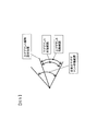
図7に示す通電回路では、アーム角度が所定上限値α(U)を越えたか否かをアーム111に設けられた近接スイッチ201で検出する。例えば、アーム111の回転軸に固定された円弧状の検出対象部材を、アーム111と共に回動する近接スイッチ201で検出する。円弧状の検出対象部材は、図8に示す上げデテント作動範囲(=下げデテント作動範囲)に対応する円弧を成し、上げデテント作動範囲では、図7に示した近接スイッチ201が検出対象部材と対向してオン状態となる。さらに、アーム角度が所定上限値α(U)となる位置(図8の上げデテント解除設定位置)を超えると、近接スイッチ201が検出対象部材と対向しなくなって、近接スイッチ201がオフ状態となる。
In the energization circuit shown in FIG. 7, the
近接スイッチ201がオン状態の場合にはリレー200が閉じて、デテントコイルC1,C2が通電状態となる。一方、近接スイッチ201がオフ状態になるとリレー200が開いてデテントコイルC1,C2の通電が遮断される。上げデテント解除設定位置においてデテントコイルC1の通電が遮断され、アーム操作レバー141が中立位置を越えて反対側の操作端位置(下げ操作端位置)側に大きく振れた場合でも、デテントコイルC2の通電が遮断されているので、アーム操作レバー141が下げ操作端位置に保持されるのを防止することができる。
When the
図7に示す変形例では、並列接続されたデテントコイルC1,C2のグランド側にリレー200を接続し、そのリレー200の開閉を近接センサ201のオンオフすることで、回路的に図8の動作を実現するようにしたが、リレー200をデテントコイルC1,C2のプラス側に配置しても良い。リレー回路で構成するので、高価なコントロールユニット10が不要となり、コストを抑制することができる。
In the modification shown in FIG. 7, the
さらに、近接センサ201のオンオフ信号をコントロールユニット10に入力し、コントロールユニット10によりデテントコイルC1,C2の通電をオンオフするようにしても良い。この場合、図5のブロック図に示したアーム角度センサ56を近接センサ201に置き換えれば良い。
Further, an on / off signal of the
図9はその場合の制御を示すフローチャートであり、この制御が所定時間間隔で繰り返し実行される。ステップS110では、近接スイッチ201がオン状態か否か、すなわち、図8の下げデテント作動範囲(=上げデテント作動範囲)であるか否かを判定する。ステップS110においてオン状態と判定されるとステップS120ヘ進み、デテントコイルC1,C2を通電状態とする。一方、ステップS110で近接センサ201がオン状態でない(すなわち、オフ状態)であると判定されると、ステップS130へ進んでデテントコイルC1,C2の通電を遮断する。このように、アーム111の角度が上げデテント解除設定値を超えると、デテントコイルC1,C2の両方が通電遮断されるので、上げデテントが解除されたときに、アーム操作レバー141が反対側の下げ操作端位置に保持されてしまうのを防止することができる。
FIG. 9 is a flowchart showing the control in that case, and this control is repeatedly executed at predetermined time intervals. In step S110, it is determined whether or not the
なお、上述した実施の形態のホイールローダでは、上げデテント機構141aおよび下げデテント機構141bを備えるアーム操作レバーを例に説明したが、操作レバーの両方の操作端位置にデテント機構を備える構成の作業車両であれば、本発明を同様に適用することができる。
In the wheel loader of the above-described embodiment, the arm operation lever including the
また、操作レバーが油圧式減圧弁である場合には、操作レバーの操作角度またはストロークに応じた油圧が減圧弁から2次圧として出力され、その2次圧に応じてコントロールバルブのスプールが変位するが、電気式の操作レバーの場合には、操作レバーの操作角度またはストロークに応じた油圧が電磁比例弁から出力され、その油圧に応じてコントロールバルブのスプールが変位することになる。 When the operating lever is a hydraulic pressure reducing valve, the hydraulic pressure corresponding to the operating angle or stroke of the operating lever is output as a secondary pressure from the pressure reducing valve, and the spool of the control valve is displaced according to the secondary pressure. However, in the case of an electric operation lever, the hydraulic pressure corresponding to the operation angle or stroke of the operation lever is output from the electromagnetic proportional valve, and the spool of the control valve is displaced according to the hydraulic pressure.
上述したように、アーム操作レバー141は握りが設けられたグリップタイプであるため、デテント解除時の中立点から反対側への振れが大きくなる傾向がある。さらに、握り部にアーム操作とは別の操作に関するスイッチ(単数または複数)が設けられる場合もあり、そのような場合には慣性による反対側への振れがさらに大きくなる。そのようなスイッチとしては、例えば、作業車両の進行方向を切り替える前後進切り替えスイッチ等がある。また、操作レバーを前後に倒すことでアーム操作が行われ、操作レバーを左右に倒すことでバケット操作が行われるような操作レバーにも、本発明は適用できる。
As described above, since the
なお、以上の説明はあくまでも一例であり、本発明はこれらの内容に限定されるものではない。本発明の技術的思想の範囲内で考えられるその他の態様も本発明の範囲内に含まれる。例えば、上述した実施形態では、図6に示すようにアーム角度αが所定上限値α(U)を超えた場合と、所定下限値α(F)を下回った場合の両方に本願発明を適用しているが、いずれか一方のみに適用しても良い。 The above description is merely an example, and the present invention is not limited to these contents. Other embodiments conceivable within the scope of the technical idea of the present invention are also included in the scope of the present invention. For example, in the above-described embodiment, the present invention is applied both when the arm angle α exceeds the predetermined upper limit value α (U) and when it falls below the predetermined lower limit value α (F) as shown in FIG. However, it may be applied to only one of them.
10…コントロールユニット、14…パイロットバルブ、41…アーム用コントロールバルブ、56…アーム角度センサ、100…ホイールローダ、111…リフトアーム(アーム)、141…アーム操作レバー、141a,141b…デテント機構、144a,144b…バネ、200…リレー、201…近接スイッチ、C1,C2…デテントコイル
DESCRIPTION OF
Claims (4)
上げ操作端位置と下げ操作端位置との間で操作可能であって、前記リフトアームの上げ下げを操作する操作レバーと、
前記上げ操作端位置に操作された前記操作レバーを、該上げ操作端位置に保持する保持機能を有する上げデテント機構と、
前記下げ操作端位置に操作された前記操作レバーを、該下げ操作端位置に保持する保持機能を有する下げデテント機構と、を備え、
前記リフトアームの角度が所定上限を超えると、前記上げデテント機構の保持機能および前記下げデテント機構の保持機能が解除され、
前記上げデテント機構は、前記操作レバーを磁力により前記上げ操作端位置に保持する上げデテントコイルを有し、
前記下げデテント機構は、前記操作レバーを磁力により前記下げ操作端位置に保持する下げデテントコイルを有し、
前記リフトアームの角度が前記所定上限を下回っている場合には前記上げデテントコイルおよび前記下げデテントコイルを通電状態とし、前記リフトアームの角度が前記所定上限を超えると前記上げデテントコイルおよび前記下げデテントコイルの通電を遮断するデテント制御回路を備える作業車両。 A lift arm connected to the front portion of the vehicle body of the work vehicle so as to be rotatable in the vertical direction;
An operation lever that is operable between a raising operation end position and a lowering operation end position, and that operates raising and lowering of the lift arm;
A raising detent mechanism having a holding function for holding the operation lever operated to the raising operation end position at the raising operation end position;
A lowering detent mechanism having a holding function for holding the operating lever operated at the lowering operation end position at the lowering operation end position;
When the angle of the lift arm exceeds a predetermined upper limit, the holding function of the raising detent mechanism and the holding function of the lowering detent mechanism are released,
The raising detent mechanism has a raising detent coil that holds the operation lever at the raising operation end position by magnetic force,
The lowering detent mechanism has a lowering detent coil that holds the operation lever at the lowering operation end position by magnetic force,
When the angle of the lift arm is below the predetermined upper limit, the raising detent coil and the lowering detent coil are energized, and when the angle of the lifting arm exceeds the predetermined upper limit, the raising detent coil and the lowering detent are A work vehicle including a detent control circuit that cuts off energization of a coil.
前記リフトアームの角度を検出するアーム角度センサと、
前記アーム角度センサで検出された角度が所定上限を超えると、前記上げデテント機構の保持機能および前記下げデテント機構の保持機能を第1の所定時間だけ解除し、前記第1の所定時間が経過した後に前記下げデテント機構の保持機能を再び動作させる制御部と、を備える作業車両。 The work vehicle according to claim 1,
An arm angle sensor for detecting the angle of the lift arm;
When the angle detected by the arm angle sensor exceeds a predetermined upper limit, the holding function of the raising detent mechanism and the holding function of the lowering detent mechanism are released for a first predetermined time, and the first predetermined time has elapsed. A work vehicle comprising a controller that later operates the holding function of the lowered detent mechanism again.
前記制御部は、
前記アーム角度センサで検出された角度が所定下限を下回ると、前記上げデテント機構の保持機能および前記下げデテント機構の保持機能を第2の所定時間だけ解除し、前記第2の所定時間が経過した後に前記上げデテント機構の保持機能を再び動作させる作業車両。 The work vehicle according to claim 2,
The controller is
When the angle detected by the arm angle sensor falls below a predetermined lower limit, the holding function of the raising detent mechanism and the holding function of the lowering detent mechanism are released for a second predetermined time, and the second predetermined time has elapsed. A work vehicle which operates the holding function of the raising detent mechanism again later.
前記デテント制御回路は、
前記所定上限を下回っているとオンし、前記所定上限を超えるとオフするスイッチと、
前記スイッチのオンオフに連動して前記上げデテントコイルおよび前記下げデテントコイルの通電を制御するリレーと、を備える作業車両。
The work vehicle according to claim 1,
The detent control circuit includes:
And Ofusu Luz switch if the if below a predetermined upper limit on, exceeds the predetermined upper limit,
A work vehicle comprising: a relay for controlling the energization of in conjunction with the on-off before kissing switch the raised detents coil and the lower detent coil.
Priority Applications (6)
| Application Number | Priority Date | Filing Date | Title |
|---|---|---|---|
| JP2014100742A JP6309817B2 (en) | 2014-05-14 | 2014-05-14 | Work vehicle |
| CN201580011784.0A CN106062284B (en) | 2014-05-14 | 2015-05-13 | Working truck |
| PCT/JP2015/063825 WO2015174469A1 (en) | 2014-05-14 | 2015-05-13 | Working vehicle |
| EP15791915.0A EP3144429B1 (en) | 2014-05-14 | 2015-05-13 | Working vehicle |
| KR1020167023944A KR101829789B1 (en) | 2014-05-14 | 2015-05-13 | Working vehicle |
| US15/122,208 US10358794B2 (en) | 2014-05-14 | 2015-05-13 | Work vehicle |
Applications Claiming Priority (1)
| Application Number | Priority Date | Filing Date | Title |
|---|---|---|---|
| JP2014100742A JP6309817B2 (en) | 2014-05-14 | 2014-05-14 | Work vehicle |
Publications (3)
| Publication Number | Publication Date |
|---|---|
| JP2015218449A JP2015218449A (en) | 2015-12-07 |
| JP2015218449A5 JP2015218449A5 (en) | 2017-04-20 |
| JP6309817B2 true JP6309817B2 (en) | 2018-04-11 |
Family
ID=54480006
Family Applications (1)
| Application Number | Title | Priority Date | Filing Date |
|---|---|---|---|
| JP2014100742A Active JP6309817B2 (en) | 2014-05-14 | 2014-05-14 | Work vehicle |
Country Status (6)
| Country | Link |
|---|---|
| US (1) | US10358794B2 (en) |
| EP (1) | EP3144429B1 (en) |
| JP (1) | JP6309817B2 (en) |
| KR (1) | KR101829789B1 (en) |
| CN (1) | CN106062284B (en) |
| WO (1) | WO2015174469A1 (en) |
Families Citing this family (2)
| Publication number | Priority date | Publication date | Assignee | Title |
|---|---|---|---|---|
| JP6791827B2 (en) | 2017-09-29 | 2020-11-25 | 株式会社小松製作所 | Work vehicle and control method of work vehicle |
| AU2020270518A1 (en) * | 2019-12-02 | 2021-06-17 | Caterpillar Global Mining Equipment Llc | Machine and method of moving upper structure of machine |
Family Cites Families (13)
| Publication number | Priority date | Publication date | Assignee | Title |
|---|---|---|---|---|
| US3487958A (en) * | 1968-01-31 | 1970-01-06 | Caterpillar Tractor Co | Self-cycling loader |
| JP2635816B2 (en) * | 1990-11-29 | 1997-07-30 | 日立建機株式会社 | Working machine operating device |
| JP2558015Y2 (en) * | 1993-05-06 | 1997-12-17 | 東洋運搬機株式会社 | Work implement leveling device |
| DE19581883B4 (en) | 1995-03-22 | 2004-09-02 | Komatsu Ltd. | Excavator bucket aligner for an industrial vehicle |
| JP3724982B2 (en) | 1999-05-19 | 2005-12-07 | 株式会社クボタ | Backhoe |
| JP2004036327A (en) | 2002-07-08 | 2004-02-05 | Tcm Corp | Loading and unloading operating apparatus |
| CA2689325A1 (en) | 2007-06-15 | 2008-12-18 | Deere & Company | Electronic parallel lift and return to carry or float on a backhoe loader |
| KR101601978B1 (en) | 2009-12-03 | 2016-03-09 | 두산인프라코어 주식회사 | Full crowd detent apparatus of wheeloader bucket |
| US8340875B1 (en) * | 2011-06-16 | 2012-12-25 | Caterpillar Inc. | Lift system implementing velocity-based feedforward control |
| CN202298691U (en) * | 2011-08-30 | 2012-07-04 | 徐工集团工程机械股份有限公司科技分公司 | Lifting limiting device with movable arm |
| JP2013167099A (en) * | 2012-02-15 | 2013-08-29 | Hitachi Constr Mach Co Ltd | Wheel loader |
| CN102733441B (en) * | 2012-06-15 | 2015-04-22 | 三一重机有限公司 | Raising speed control energy saving system and method for excavator |
| US8689471B2 (en) * | 2012-06-19 | 2014-04-08 | Caterpillar Trimble Control Technologies Llc | Method and system for controlling an excavator |
-
2014
- 2014-05-14 JP JP2014100742A patent/JP6309817B2/en active Active
-
2015
- 2015-05-13 EP EP15791915.0A patent/EP3144429B1/en active Active
- 2015-05-13 KR KR1020167023944A patent/KR101829789B1/en active IP Right Grant
- 2015-05-13 US US15/122,208 patent/US10358794B2/en active Active
- 2015-05-13 CN CN201580011784.0A patent/CN106062284B/en active Active
- 2015-05-13 WO PCT/JP2015/063825 patent/WO2015174469A1/en active Application Filing
Also Published As
| Publication number | Publication date |
|---|---|
| EP3144429B1 (en) | 2020-03-04 |
| US10358794B2 (en) | 2019-07-23 |
| KR101829789B1 (en) | 2018-02-19 |
| WO2015174469A1 (en) | 2015-11-19 |
| US20160369479A1 (en) | 2016-12-22 |
| CN106062284A (en) | 2016-10-26 |
| EP3144429A4 (en) | 2018-01-24 |
| KR20160115968A (en) | 2016-10-06 |
| EP3144429A1 (en) | 2017-03-22 |
| CN106062284B (en) | 2018-01-23 |
| JP2015218449A (en) | 2015-12-07 |
Similar Documents
| Publication | Publication Date | Title |
|---|---|---|
| TWI310353B (en) | Industrial vehicle | |
| US11408148B2 (en) | Working machine with control device to control operation allowable state and operation restriction state | |
| JP4373820B2 (en) | Forward / backward operation device for work machines | |
| US10983539B2 (en) | Work machine | |
| JP6309817B2 (en) | Work vehicle | |
| JP2008248981A (en) | Traveling system of work machine | |
| JP7284019B2 (en) | System and method for controlling bulldozer | |
| US20070295147A1 (en) | Joystick Device With Electric Latching Detents | |
| JP4936514B2 (en) | Industrial vehicle hydraulic system | |
| JP7080783B2 (en) | Work machine | |
| WO2021186849A1 (en) | Motor grader and control method of motor grader | |
| JP5757690B2 (en) | Working machine | |
| JP2009062793A (en) | Construction machine | |
| JP2009243077A (en) | Traveling control apparatus of working machine | |
| JP4798658B2 (en) | Industrial vehicle hydraulic system | |
| JP6433750B2 (en) | Steering control device for work vehicle | |
| US20180093872A1 (en) | Industrial truck with an operating lever as well as method for operating said industrial truck | |
| JP2017057607A (en) | Construction machine | |
| WO2021186850A1 (en) | Motor grader and method for controlling motor grader | |
| JP2006188356A (en) | Lever operational reaction force controller of crane | |
| JPH06278992A (en) | Operating device for direction switching valve in mobile crane | |
| JPH05195550A (en) | Hydraulic actuator controller in earth-moving machine | |
| JP2008050120A (en) | Load handling control device of industrial vehicle | |
| JP2007239363A (en) | Locking device and operating machine equipped with the same | |
| JPH05195549A (en) | Hydraulic actuator controller in earth-moving machine |
Legal Events
| Date | Code | Title | Description |
|---|---|---|---|
| A711 | Notification of change in applicant |
Free format text: JAPANESE INTERMEDIATE CODE: A712 Effective date: 20160722 |
|
| RD02 | Notification of acceptance of power of attorney |
Free format text: JAPANESE INTERMEDIATE CODE: A7422 Effective date: 20160826 |
|
| RD04 | Notification of resignation of power of attorney |
Free format text: JAPANESE INTERMEDIATE CODE: A7424 Effective date: 20161024 |
|
| A521 | Request for written amendment filed |
Free format text: JAPANESE INTERMEDIATE CODE: A523 Effective date: 20170316 |
|
| A621 | Written request for application examination |
Free format text: JAPANESE INTERMEDIATE CODE: A621 Effective date: 20170316 |
|
| A131 | Notification of reasons for refusal |
Free format text: JAPANESE INTERMEDIATE CODE: A131 Effective date: 20180109 |
|
| A521 | Request for written amendment filed |
Free format text: JAPANESE INTERMEDIATE CODE: A523 Effective date: 20180302 |
|
| TRDD | Decision of grant or rejection written | ||
| A01 | Written decision to grant a patent or to grant a registration (utility model) |
Free format text: JAPANESE INTERMEDIATE CODE: A01 Effective date: 20180313 |
|
| A61 | First payment of annual fees (during grant procedure) |
Free format text: JAPANESE INTERMEDIATE CODE: A61 Effective date: 20180315 |
|
| R150 | Certificate of patent or registration of utility model |
Ref document number: 6309817 Country of ref document: JP Free format text: JAPANESE INTERMEDIATE CODE: R150 |
|
| S111 | Request for change of ownership or part of ownership |
Free format text: JAPANESE INTERMEDIATE CODE: R313111 |
|
| R350 | Written notification of registration of transfer |
Free format text: JAPANESE INTERMEDIATE CODE: R350 |