JP6307662B2 - Radio receiver for carrier aggregation - Google Patents
Radio receiver for carrier aggregation Download PDFInfo
- Publication number
- JP6307662B2 JP6307662B2 JP2017513536A JP2017513536A JP6307662B2 JP 6307662 B2 JP6307662 B2 JP 6307662B2 JP 2017513536 A JP2017513536 A JP 2017513536A JP 2017513536 A JP2017513536 A JP 2017513536A JP 6307662 B2 JP6307662 B2 JP 6307662B2
- Authority
- JP
- Japan
- Prior art keywords
- receive
- path
- reception path
- receiver circuit
- reception
- Prior art date
- Legal status (The legal status is an assumption and is not a legal conclusion. Google has not performed a legal analysis and makes no representation as to the accuracy of the status listed.)
- Expired - Fee Related
Links
- 230000002776 aggregation Effects 0.000 title claims description 6
- 238000004220 aggregation Methods 0.000 title claims description 6
- 238000012545 processing Methods 0.000 claims description 49
- 238000000034 method Methods 0.000 claims description 34
- 238000005259 measurement Methods 0.000 claims description 27
- 230000010267 cellular communication Effects 0.000 claims description 14
- 238000004891 communication Methods 0.000 claims description 14
- 238000004590 computer program Methods 0.000 claims description 11
- 230000008569 process Effects 0.000 claims description 11
- 239000000969 carrier Substances 0.000 claims description 8
- 238000012805 post-processing Methods 0.000 claims description 6
- 238000010586 diagram Methods 0.000 description 11
- 238000001914 filtration Methods 0.000 description 4
- 238000006243 chemical reaction Methods 0.000 description 3
- 238000013461 design Methods 0.000 description 3
- 238000004422 calculation algorithm Methods 0.000 description 2
- 238000004364 calculation method Methods 0.000 description 2
- 230000015556 catabolic process Effects 0.000 description 2
- 230000008859 change Effects 0.000 description 2
- 238000006731 degradation reaction Methods 0.000 description 2
- 230000001419 dependent effect Effects 0.000 description 2
- 238000001514 detection method Methods 0.000 description 2
- 230000006872 improvement Effects 0.000 description 2
- 230000002194 synthesizing effect Effects 0.000 description 2
- 241000760358 Enodes Species 0.000 description 1
- 238000003491 array Methods 0.000 description 1
- 230000009286 beneficial effect Effects 0.000 description 1
- 230000005540 biological transmission Effects 0.000 description 1
- 230000015572 biosynthetic process Effects 0.000 description 1
- 230000000903 blocking effect Effects 0.000 description 1
- 230000001413 cellular effect Effects 0.000 description 1
- 230000007423 decrease Effects 0.000 description 1
- 230000000630 rising effect Effects 0.000 description 1
- 230000008054 signal transmission Effects 0.000 description 1
- 230000001629 suppression Effects 0.000 description 1
- 238000003786 synthesis reaction Methods 0.000 description 1
Images


Classifications
-
- H—ELECTRICITY
- H03—ELECTRONIC CIRCUITRY
- H03D—DEMODULATION OR TRANSFERENCE OF MODULATION FROM ONE CARRIER TO ANOTHER
- H03D7/00—Transference of modulation from one carrier to another, e.g. frequency-changing
- H03D7/14—Balanced arrangements
- H03D7/1425—Balanced arrangements with transistors
- H03D7/1466—Passive mixer arrangements
-
- H—ELECTRICITY
- H04—ELECTRIC COMMUNICATION TECHNIQUE
- H04B—TRANSMISSION
- H04B1/00—Details of transmission systems, not covered by a single one of groups H04B3/00 - H04B13/00; Details of transmission systems not characterised by the medium used for transmission
- H04B1/005—Details of transmission systems, not covered by a single one of groups H04B3/00 - H04B13/00; Details of transmission systems not characterised by the medium used for transmission adapting radio receivers, transmitters andtransceivers for operation on two or more bands, i.e. frequency ranges
- H04B1/0053—Details of transmission systems, not covered by a single one of groups H04B3/00 - H04B13/00; Details of transmission systems not characterised by the medium used for transmission adapting radio receivers, transmitters andtransceivers for operation on two or more bands, i.e. frequency ranges with common antenna for more than one band
-
- H—ELECTRICITY
- H04—ELECTRIC COMMUNICATION TECHNIQUE
- H04B—TRANSMISSION
- H04B1/00—Details of transmission systems, not covered by a single one of groups H04B3/00 - H04B13/00; Details of transmission systems not characterised by the medium used for transmission
- H04B1/005—Details of transmission systems, not covered by a single one of groups H04B3/00 - H04B13/00; Details of transmission systems not characterised by the medium used for transmission adapting radio receivers, transmitters andtransceivers for operation on two or more bands, i.e. frequency ranges
- H04B1/0067—Details of transmission systems, not covered by a single one of groups H04B3/00 - H04B13/00; Details of transmission systems not characterised by the medium used for transmission adapting radio receivers, transmitters andtransceivers for operation on two or more bands, i.e. frequency ranges with one or more circuit blocks in common for different bands
-
- H—ELECTRICITY
- H04—ELECTRIC COMMUNICATION TECHNIQUE
- H04L—TRANSMISSION OF DIGITAL INFORMATION, e.g. TELEGRAPHIC COMMUNICATION
- H04L27/00—Modulated-carrier systems
- H04L27/26—Systems using multi-frequency codes
- H04L27/2601—Multicarrier modulation systems
- H04L27/2647—Arrangements specific to the receiver only
-
- H—ELECTRICITY
- H04—ELECTRIC COMMUNICATION TECHNIQUE
- H04L—TRANSMISSION OF DIGITAL INFORMATION, e.g. TELEGRAPHIC COMMUNICATION
- H04L5/00—Arrangements affording multiple use of the transmission path
- H04L5/0001—Arrangements for dividing the transmission path
- H04L5/0003—Two-dimensional division
- H04L5/0005—Time-frequency
- H04L5/0007—Time-frequency the frequencies being orthogonal, e.g. OFDM(A), DMT
- H04L5/001—Time-frequency the frequencies being orthogonal, e.g. OFDM(A), DMT the frequencies being arranged in component carriers
Description
本発明は、キャリアアグリゲーションシナリオにおいて動作可能な無線受信機回路に関する。 The present invention relates to a radio receiver circuit operable in a carrier aggregation scenario.
セルラー通信ネットワークにおいて、時にUE(ユーザ機器)として言及されるワイヤレス端末は、セルラー通信ネットワークの基地局とワイヤレスで通信する。ダウンリンクでは、基地局からUEへ、UEは単一の無線周波数(RF)キャリアに関連付けられる単一の周波数帯域において信号を受信し得る。(例えば、ダウンリンクビットレートの観点で)キャパシティを改善する目的で、キャリアアグリゲーション(CA)の概念が3GPP(3rd Generation Partnership Program)標準に導入されている。CAを用いて、UEは、複数のRFキャリアを同時に受信し得る。それらRFキャリアは、通常は、コンポーネントキャリアあるいはCCとして言及される。各CC上では、ペイロードデータ及び/又は制御情報を搬送する、例えばOFDMA(直交周波数分割多重アクセス)信号又はCDMA(符号分割多重アクセス)信号といった情報信号が変調される。それらCCは同じ動作周波数帯域内に位置してもよく、そのケースにおいてCAはイントラ帯域CAとして言及される。代替的に、それらCCは異なる動作周波数帯域内に位置してもよく、そのケースにおいてCAはインター帯域CAとして言及される。イントラ帯域CAについて、複数のCCは、(周波数において)連続的に位置してもよく、そのケースにおいてCAは連続CAとして言及され、又は、(周波数において)周波数ギャップを挟んで非連続的に位置してもよく、そのケースにおいてCAは非連続的CAとして言及される。1つのシナリオにおいて、UEは、セルラー通信ネットワークのプライマリセル(PCell)に関連付けられるプライマリCC(PCC)を割り当てられ得る。どのような理由であれ、ダウンリンクキャパシティの増加が必要とされる場合、UEは、追加的に、それぞれのセカンダリセル(SCell)に関連付けられる1つ以上のセカンダリCC(SCC)を割り当てられ得る。 In a cellular communication network, a wireless terminal, sometimes referred to as a UE (user equipment), communicates wirelessly with a base station of the cellular communication network. On the downlink, from the base station to the UE, the UE may receive signals in a single frequency band associated with a single radio frequency (RF) carrier. For the purpose of improving capacity (for example, in terms of downlink bit rate), the concept of carrier aggregation (CA) has been introduced into the 3rd Generation Partnership Program (3GPP) standard. With CA, the UE may receive multiple RF carriers simultaneously. These RF carriers are usually referred to as component carriers or CCs. On each CC, an information signal, for example an OFDMA (Orthogonal Frequency Division Multiple Access) signal or a CDMA (Code Division Multiple Access) signal, which carries payload data and / or control information, is modulated. The CCs may be located within the same operating frequency band, in which case CA is referred to as intra-band CA. Alternatively, the CCs may be located in different operating frequency bands, in which case CA is referred to as inter-band CA. For intra-band CA, multiple CCs may be located consecutively (in frequency), in which case CA is referred to as a continuous CA, or located discontinuously across a frequency gap (in frequency). In that case, the CA is referred to as a discontinuous CA. In one scenario, the UE may be assigned a primary CC (PCC) associated with the primary cell (PCell) of the cellular communication network. If for any reason an increase in downlink capacity is required, the UE may additionally be assigned one or more secondary CCs (SCCs) associated with each secondary cell (SCell). .
特に非連続的CAシナリオにおいて、UEが複数のCCを受信することを可能にするための1つの解決策は、各々が同じアンテナへ例えば共通の低雑音増幅器(LNA)を介して接続される複数の受信パスを伴う受信機回路を使用することである。各受信パスは、複数のCCのうちの特定の1つの受信に責任を有し得る。例えば、各受信パスは、ミキサユニットを備えるダイレクトコンバージョン型であってよく、ミキサユニットは、当該ミキサユニットが直接的に特定のCCをベースバンドへとダウンコンバートするように選択される周波数を有するLO信号で駆動される。よって、各処理パスのLO信号周波数は、受信するように設定されるCCのRF周波数に依存して選択され得る。 One solution to allow a UE to receive multiple CCs, particularly in non-continuous CA scenarios, is multiple multiples each connected to the same antenna, eg via a common low noise amplifier (LNA). Is to use a receiver circuit with a receive path. Each receive path may be responsible for receiving a specific one of the multiple CCs. For example, each receive path may be a direct conversion type with a mixer unit, which is a LO having a frequency selected such that the mixer unit directly downconverts a particular CC to baseband. Driven by a signal. Thus, the LO signal frequency for each processing path can be selected depending on the RF frequency of the CC set to receive.
性能を高めるために、CA動作のために意図された受信機回路を非CA(あるいは「シングルキャリア」)動作において効率的に再使用し得る、という考察に本発明の実施形態は基づいている。 To enhance performance, embodiments of the present invention are based on the consideration that a receiver circuit intended for CA operation can be efficiently reused in non-CA (or “single carrier”) operation.
第1の局面に従えば、CAモード及び非CAモードで動作するように構成可能な無線受信機回路であって、CAモードでは複数のコンポーネントキャリア(CC)を受信するものとされ、非CAモードでは単一のCCを受信するものとされる、無線受信機回路、が提供される。無線受信機回路は、アンテナへ動作可能に接続されるように構成される第1受信パスと、同じアンテナへ動作可能に接続されるように構成される第2受信パスと、を含む。さらに、無線受信機回路は、第1受信パス及び第2受信パスへ動作可能に接続される制御ユニット、を含む。制御ユニットは、CAモードにおいて、上記複数のCCのうちの第1CCを受信するように第1受信パスを制御し、及び、上記複数のCCのうちの第1CCとは別個の第2CCを受信するように第2受信パスを制御する、ように適合される。さらに、制御ユニットは、非CAモードにおいて、同じ単一のCCを双方が受信するように、第1受信パス及び第2受信パスを選択的に制御する、ように適合される。 According to a first aspect, a radio receiver circuit configurable to operate in a CA mode and a non-CA mode, wherein a plurality of component carriers (CCs) are received in the CA mode, the non-CA mode A wireless receiver circuit is provided which is intended to receive a single CC. The wireless receiver circuit includes a first receive path configured to be operably connected to the antenna and a second receive path configured to be operably connected to the same antenna. Further, the wireless receiver circuit includes a control unit operatively connected to the first receive path and the second receive path. The control unit controls the first reception path so as to receive the first CC of the plurality of CCs in the CA mode, and receives the second CC that is separate from the first CC of the plurality of CCs. Adapted to control the second receive path. Furthermore, the control unit is adapted to selectively control the first receive path and the second receive path so that both receive the same single CC in non-CA mode.
無線受信機回路は、アンテナへ第1受信パス及び第2受信パスの双方を動作可能に接続する、ように構成される低雑音増幅器、を含み得る。 The wireless receiver circuit may include a low noise amplifier configured to operably connect both the first receive path and the second receive path to the antenna.
第1受信パスは、第1局部発振器(LO)信号で駆動されるように構成されるミキサユニットを含み得る。第2受信パスは、第2LO信号で駆動されるように構成されるミキサユニットを含み得る。制御ユニットは、CAモードにおいて、第1受信パスによる第1CCの受信を可能にするために第1LO信号の周波数を制御し、及び、第2受信パスによる第2CCの受信を可能にするために第2LO信号の周波数を制御する、ように適合され得る。 The first receive path may include a mixer unit configured to be driven with a first local oscillator (LO) signal. The second receive path may include a mixer unit configured to be driven with a second LO signal. In the CA mode, the control unit controls the frequency of the first LO signal to enable reception of the first CC by the first reception path and the second CC to enable reception of the second CC by the second reception path. It can be adapted to control the frequency of the 2LO signal.
制御ユニットは、非CAモードにおいて且つ第1受信パス及び第2受信パスの双方による同じ単一のCCの受信を可能にするために、第1LO信号の周波数を第2LO信号の周波数と同じになるように制御する、ように適合され得る。 The control unit makes the frequency of the first LO signal the same as the frequency of the second LO signal in order to enable reception of the same single CC in both non-CA mode and by both the first and second reception paths. Can be adapted to control.
無線受信機回路は、非CAモードにおいて、第1受信パスの出力信号を第2受信パスの出力信号と合成することにより、合成された出力信号を生成する、ように構成される処理回路、を含み得る。制御ユニットは、非CAモードにおいて、第1受信パス及び第2受信パスが双方とも単一の周波数帯域における同じ信号を受信するように制御される際に、第1受信パスの利得及び周波数帯域のうちの少なくとも1つを、第2受信パスの利得及び周波数帯域のうちの当該少なくとも1つと同じになるように制御する、ように適合され得る。 A processing circuit configured to generate a combined output signal by combining the output signal of the first reception path with the output signal of the second reception path in the non-CA mode; May be included. When the control unit is controlled so that both the first reception path and the second reception path receive the same signal in a single frequency band in the non-CA mode, the gain of the first reception path and the frequency band It may be adapted to control at least one of them to be the same as the at least one of the gain and frequency band of the second receive path.
無線受信機回路は、非CAモードにおいて、第1受信パスの出力信号及び第2受信パスの出力信号を別々に処理することにより、第1の処理後信号及び第2の処理後信号をそれぞれ生成する、ように構成される処理回路、を含み得る。制御ユニットは、非CAモードにおいて、第1受信パス及び第2受信パスが双方とも同じ単一のCCを受信するように制御される際に、第1受信パス及び第2受信パスのうちの一方のパスの利得を第1受信パス及び第2受信パスのうちの他方のパスの利得よりも高くなるように制御する、ように適合され得る。処理回路は、例えば、第1受信パスからの出力信号に対して及び第2受信パスからの出力信号に対して信号強度測定を実行して、非CAモードにおけるさらなる受信期間中に使用されるべき利得設定を決定する、ように構成され得る。 The radio receiver circuit generates the first post-processing signal and the second post-processing signal by separately processing the output signal of the first reception path and the output signal of the second reception path in the non-CA mode, respectively. Processing circuitry configured to be included. In the non-CA mode, the control unit controls one of the first reception path and the second reception path when the first reception path and the second reception path are both controlled to receive the same single CC. The gain of the second path may be controlled to be higher than the gain of the other of the first reception path and the second reception path. The processing circuit should be used during further reception periods in non-CA mode, for example, performing signal strength measurements on the output signal from the first receive path and on the output signal from the second receive path. It may be configured to determine a gain setting.
制御ユニットは、非CAモードにおいて、第2受信パスを選択的に無効化する、ように適合され得る。 The control unit may be adapted to selectively disable the second receive path in non-CA mode.
無線受信機回路は、セルラー通信システムにおいて動作するように適合され得る。 The wireless receiver circuit may be adapted to operate in a cellular communication system.
第2の局面に従えば、上記第1の局面に従った無線受信機回路と、無線受信機回路の第1受信パス及び第2受信パスの双方が動作可能に接続されるアンテナと、を含む、無線通信装置、が提供される。 According to a second aspect, the wireless receiver circuit according to the first aspect, and an antenna to which both the first reception path and the second reception path of the wireless receiver circuit are operatively connected are included. A wireless communication device.
無線通信装置は、セルラー通信システムのための端末であり得る。端末は、例えば、携帯電話、タブレットコンピュータ、ポータブルコンピュータ、又はマシンタイプ通信デバイスであり得る。 The wireless communication device may be a terminal for a cellular communication system. The terminal can be, for example, a mobile phone, a tablet computer, a portable computer, or a machine type communication device.
第3の局面に従えば、CAモード及び非CAモードで動作するように構成可能な無線受信機回路を動作させる方法が提供される。無線受信機回路は、CAモードでは複数のコンポーネントキャリア(CC)を受信するものとされ、非CAモードでは単一のCCを受信するものとされる。無線受信機回路は、アンテナへ動作可能に接続される第1受信パスと、同じアンテナへ動作可能に接続される第2受信パスと、第1受信パス及び第2受信パスへ動作可能に接続される制御ユニットと、を含む。方法は、CAモードにおいて、制御ユニットにより、上記複数のCCのうちの第1CCを受信するように第1受信パスを制御し、及び、上記複数のCCのうちの第1CCとは別個の第2CCを受信するように第2受信パスを制御すること、を含む。さらに、上記方法は、非CAモードにおいて、制御ユニットにより、同じ単一のCCを双方が受信するように、第1受信パス及び第2受信パスを選択的に制御すること、を含む。 According to a third aspect, a method is provided for operating a radio receiver circuit that is configurable to operate in a CA mode and a non-CA mode. The radio receiver circuit is assumed to receive a plurality of component carriers (CC) in the CA mode, and to receive a single CC in the non-CA mode. The radio receiver circuit is operably connected to a first receive path operably connected to the antenna, a second receive path operably connected to the same antenna, and the first receive path and the second receive path. A control unit. In the CA mode, the method controls a first reception path so as to receive a first CC of the plurality of CCs by a control unit, and a second CC separate from the first CC of the plurality of CCs. Controlling the second reception path to receive the signal. Further, the method includes selectively controlling the first reception path and the second reception path by the control unit so that both receive the same single CC in the non-CA mode.
第4の局面に従えば、無線受信機回路の制御ユニットによって実行された場合に、上記第3の局面に従った方法を実行するためのコンピュータプログラムコード、を含む、コンピュータプログラムプロダクト、が提供される。 According to a fourth aspect, there is provided a computer program product comprising computer program code for performing the method according to the third aspect when executed by a control unit of a radio receiver circuit. The
第5の局面に従えば、無線受信機回路の制御ユニットによって実行された場合に、上記第3の局面に従った方法を実行するためのコンピュータプログラムコード、を含むコンピュータプログラムプロダクトが記憶された、(非一時的なコンピュータ読取可能な媒体といった)コンピュータ読取可能な媒体、が提供される。コンピュータ読取可能な媒体は、例えば、非一時的なコンピュータ読取可能な媒体であってよい。 According to a fifth aspect, there is stored a computer program product comprising computer program code for executing a method according to the third aspect when executed by a control unit of a radio receiver circuit. A computer readable medium (such as a non-transitory computer readable medium) is provided. The computer readable medium may be, for example, a non-transitory computer readable medium.
さらなる実施形態は、従属請求項において定義される。本明細書において使用される場合、「含む(comprises/comprising)」という用語は、示された特徴、整数、ステップ、又は構成要素の存在を特定するものと解釈され、1つ以上の他の特徴、整数、ステップ、構成要素、若しくはそれらの集合の存在又は追加を排除するものではない、ということが強調されるべきである。 Further embodiments are defined in the dependent claims. As used herein, the term “comprises / comprising” is to be interpreted as identifying the presence of the indicated feature, integer, step, or component, and one or more other features. It should be emphasized that it does not exclude the presence or addition of integers, steps, components, or sets thereof.
発明の実施形態のさらなる目的、特徴、及び利点は、添付の図面が参照される以下の詳細な説明から明らかになるであろう。 Further objects, features and advantages of embodiments of the invention will become apparent from the following detailed description when taken in conjunction with the accompanying drawings.
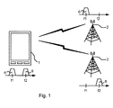
図1及び図2は、本発明の実施形態が用いられ得る通信環境を示している。 1 and 2 illustrate a communication environment in which embodiments of the present invention may be used.
図1において、セルラー通信システムのための端末1として示される無線通信装置1は、キャリアアグリゲーション(CA)モードでセルラー通信システムとワイヤレス通信を行っている。図中、端末1は、携帯電話(あるいは、所謂スマートフォンといった「セルラー電話」)として描かれているが、タブレットコンピュータ、ポータブルコンピュータ、又はマシンタイプ通信デバイス(例えば、センサ、センサシステム、若しくは、セルラー通信システムを介して通信するように構成される類似物)といった、セルラー通信システムのための他のいずれのタイプの端末であることもできる。簡潔にするために、無線通信装置1は以下において「端末1」として言及される。CAモードでは、端末1の無線受信機回路(下でさらに説明する)は、複数の(ダウンリンク)コンポーネントキャリア(CC)を受信するように構成され、それらCCは連続的であっても非連続的であってもよい。通常、CCのうちの1つは(上の背景技術の段落で述べたように)PCellのPCCであり、他のCCは、(やはり上の背景技術の段落で述べたように)SCellのSCCである。図2において、複数のCCは、第1の(RF)キャリア周波数f1における第1周波数CC6と、第2の(RF)キャリア周波数f2における、第1CC6とは別個の第2CC8と、を含む。第1CC6は例えばPCCであり、第2CC8は例えばSCCであってよく、又は逆であってもよい。概して、2つ以上のSCellが存在し得るため、複数のCCの中には3つ以上のCCが存在し得る。図1において、第1CC6は、第1基地局2から送信されるように示され、第2CC8は、第2基地局3から送信されるように示されているが、概して、それらCCは同じ基地局から送信されてもよい。一方又は両方の基地局2、3は、例えば、UTRAN(Universal Terrestrial Radio Access Network)のNodeB又はeUTRAN(evolved UTRAN)のeNodeBといったマクロ基地局、マイクロ基地局、ピコ基地局、及びフェムト基地局という群のうちのものであり得るが、他の種類の現行の若しくは将来の基地局であってもよい。さらに、図1において、第1CC6及び第2CC8は、周波数ギャップを間に挟む非連続的(あるいは非隣接)CCとして示されているが、他の実施形態又はシナリオでは、連続的(あるいは隣接)CCであってもよい。
In FIG. 1, a
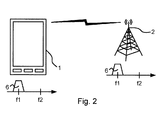
図2において、端末1は、非CAモードでセルラー通信システムとワイヤレス通信を行っている。非CAモードでは、端末1の無線受信機回路は、単一のCCを受信するように構成される。図2において、単一のCCは、図1における第1基地局2からの第1CC6と同じCCとして示されているが、(限定はしないが図1における第2CC8といった)他の何らかのCCであってもよく、及び/又は、(限定はしないが図1における第2基地局3といった)他の何らかの基地局からのものであってもよい。
In FIG. 2, the
図3は、一実施形態に従った端末1の一部分の簡略化されたブロック図を示す。上述の無線受信機回路は、参照番号10で示されている。当該回路は、端末10のアンテナ15へと、無線受信機回路10のアンテナポート20を介して動作可能に接続される。端末1は、当然ながら、1つ以上の送信機、1つ以上のプロセッサ、入力及び出力デバイス(例えば、ボタン、ディスプレイ、タッチスクリーン等)等といった、多数の他の部品をも含み得る。簡略化のために、そうした他の部品は図3には示されない。
FIG. 3 shows a simplified block diagram of a portion of
図3において、端末1は、単一のアンテナ15を有するものとして示されている。他の実施形態において、端末1は、複数のアンテナを有してもよい。例えば、端末1は、ダイバーシティ受信のために複数の受信アンテナを有してもよい。これが図4に例示されている。図4は、端末1の別の実施形態の簡略化されたブロック図を示す。図1の実施形態の場合と同様に、図4における端末1の実施形態は、無線受信機回路10のアンテナポート20を介して端末1のアンテナ15へ動作可能に接続される無線受信機回路10を含む。加えて、端末1は、別の無線受信機回路10’及び別のアンテナ15’を含み、無線受信機回路10’は、無線受信機回路10’のアンテナポート20’を介して端末1のアンテナ15’へ動作可能に接続される。以下に、無線受信機回路10の実施形態について説明する。無線受信機回路10’は、例えば無線受信機回路10と同じように設計されてよい。
In FIG. 3, the
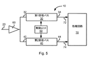
図5は、無線受信機回路10の一実施形態のブロック図を示す。上記のように、無線受信機回路10は、CAモードで動作するように構成可能であり、CAモードでは無線受信機回路10は、CC6及びCC8といった複数のCCを受信するものとされる(図1)。さらに、無線受信機回路10は、非CAモードで動作するように構成可能であり、非CAモードでは無線受信機回路10は、CC6といった単一のCCを受信するものとされる(図2)。無線受信機回路10は、例えば、セルラー通信システムにおいて動作するように適合され得る。
FIG. 5 shows a block diagram of an embodiment of the
無線受信機回路10は、アンテナへ動作可能に接続されるように構成される第1受信パス30を含む。図5に例示される実施形態において、第1受信パス30は、アンテナ15へ動作可能に接続されるように構成される入力ポート32を有する。さらに、図5に例示される実施形態において、第1受信パス30は、第1受信パス30の出力信号を提供するように構成される出力ポート34を有する。
The
さらに、無線受信機回路10は、同じアンテナ15へ動作可能に接続されるように構成される第2受信パス40を含む。図5に例示される実施形態において、第2受信パス40は、アンテナ15へ動作可能に接続されるように構成される入力ポート42を有する。さらに、図5に例示される実施形態において、第2受信パス40は、第2受信パス40の出力信号を提供するように構成される出力ポート44を有する。
Further, the
図5に例示される実施形態において、無線受信機回路10は、第1受信パス30及び第2受信パス40に共通のLNA(低雑音増幅器)60を含む。LNA60は、無線受信機回路10のアンテナポート20を介して第1受信パス30及び第2受信パス40の双方をアンテナ15へと動作可能に接続するように構成される。他の実施形態において、無線受信機回路10は、無線受信機回路10のアンテナポート20を介して第1受信パス30及び第2受信パス40をそれぞれアンテナ15へと動作可能に接続するように構成される別々のLNAを含んでもよい。
In the embodiment illustrated in FIG. 5, the
無線受信機回路10は、第1受信パス30及び第2受信パス40の動作を制御するために第1受信パス30及び第2受信パス40へ動作可能に接続される制御ユニット50をさらに含む。その上、図5に例示される実施形態において、無線受信機回路10は、第1受信パス30及び第2受信パス40へ動作可能に接続され且つ第1受信パス30及び第2受信パス40からの出力信号を処理するように構成される処理回路70を含む。図5に示されるように、処理回路70は、第1受信パス30の出力ポート34へ接続される入力ポート72と、第2受信パス40の出力ポート44へ接続される入力ポート74と、を有し得る。処理回路70は、例えば、無線受信機回路10のベースバンドプロセッサといったデジタル信号プロセッサを含んでもよく、そうしたプロセッサであってもよく、又は、そうしたプロセッサの一部であってもよい。同様に、制御ユニット50は、無線受信機回路10のベースバンドプロセッサといったデジタル信号プロセッサを含んでもよく、そうしたプロセッサであってもよく、又は、そうしたプロセッサの一部であってもよく、場合によっては、直前の文で述べた処理回路70についてのデジタル信号プロセッサと同じプロセッサであってもよい。
The
制御ユニット50は、CAモードでは、複数の周波数帯域のうちの第1CC6を受信するように第1受信パス30を制御し、及び、複数のCCのうちの第2CC8を受信するように第2受信パスを制御する、ように適合される。その際、処理回路70は、例えばよく知られた技術に従って、第1受信パス30及び第2受信パス40からの出力信号を処理して、それぞれの周波数帯域における信号上で送信されたデータを回復することができ、それら処理は、例えば出力信号の復調及び復号を含む。
In the CA mode, the
発明者らは、無線受信機回路10の増加したダイナミックレンジが必要とされる状況で、そのダイナミックレンジを大きくするために、CAモードでCA受信のために使用されるハードウェアを、非CAモードにおいて効率的に再使用することができる、ということに気付いた。発明者らにより識別されたそうした状況の例は、受信される信号が比較的弱い状況、障害となる干渉物(blocking interferer(s))が存在する状況、及び、受信される信号の強度が無線受信機回路10には当初不明である場合の信号測定期間中、である。上記のことは、非CAモードにおいて、第1受信パス30及び第2受信パス40の双方を、同じ単一のCC6を双方ともが受信するように制御する、ことによって達成されることができる。第1受信パス及び第2受信パスからの出力信号を処理回路70がどのように処理することができるかについては様々な選択肢があり、それらの例は、種々の実施形態の文脈において下にさらに説明される。したがって、本発明の実施形態によれば、制御ユニット50は、非CAモードにおいて、同じ単一のCC6を双方が受信するように第1受信パス30及び第2受信パス40を選択的に制御する、ように適合される。
In the situation where the increased dynamic range of the
同じ単一のCC6を双方が受信するように第1受信パス30及び第2受信パス40の双方を使用すると、受信パスのうちの一方(例えば第1受信パス30)のみを使用しその間他方の受信パス(例えば第2受信パス40)を無効化する場合と比較して、電力消費はより多くなる。そのため、いくつかの実施形態によれば、同じ単一のCC6を双方が受信するように第1受信パス30及び第2受信パス40の双方を使用することによってもたらされる追加のダイナミックレンジが実際に必要とされる場合を除いては、このように双方の受信パスを使用することを避けることが推奨される。そのため、いくつかの実施形態によれば、制御ユニット50は、非CAモードでは、第2受信パス40を選択的に無効化する、ように適合される。
If both the
図6は、無線受信機回路10の一実施形態を図5におけるブロック図よりもいくぶんより詳細に示すブロック図である。図6に示されるように、第1受信パス30は、第1局部発振器(LO)信号で駆動されるように構成されるミキサユニット100を含み得る。さらに、図6に示されるように、第2受信パス40は、第2LO信号で駆動されるように構成されるミキサユニット200を含み得る。CA受信を容易にするために、制御ユニット50は、CAモードでは、第1受信パス30による第1CC6の受信を可能にするために第1LO信号の周波数を制御し、及び、第2受信パス40による第2CC8の受信を可能にするために第2LO信号の周波数を制御する、ように適合され得る。
FIG. 6 is a block diagram illustrating one embodiment of the
いくつかの実施形態において、第1LO信号及び第2LO信号は、別個のLOユニットによって生成される別個のLO信号である。例えば、図6に示されるように、第1受信パス30は、第1LO信号を生成するように構成されるLOユニット110を含み、第2受信パス40は、第2LO信号を生成するように構成される別個のLOユニット210を含み得る。その場合、第1受信パス30及び第2受信パス40は、例えば、双方ともダイレクトコンバージョン受信機として動作し得る。そのケースにおいて、制御ユニット50は、CAモードでは、第1LO信号の周波数及び第2LO信号の周波数を、それぞれ第1CC6の中心周波数f1及び第2CC8の中心周波数f2に等しく又はほぼ等しくなるように制御する、ように適合され得る。さらに、非CAモードにおける第1受信パス30及び第2受信パス40の双方による同じ単一のCC6の受信を可能にするために、制御ユニット50は、非CAモードでは、第1LO信号の周波数を第2LO信号の周波数と同じになるように制御する、ように適合され得る。この同じ周波数は、例えば、単一のCC6の中心周波数f1に等しい又はほぼ等しいものであってよく、このケースにおいて、第1受信パス30及び第2受信パス40は双方とも、ダイレクトコンバージョン受信機として動作するように構成される。
In some embodiments, the first LO signal and the second LO signal are separate LO signals generated by separate LO units. For example, as shown in FIG. 6, the first receive
いくつかの実施形態において、第1LO信号及び第2LO信号は、少なくとも非CAモードでは、無線受信機回路10内に含まれる共通のLOユニット(例えば、図6におけるLOユニット110又はLOユニット210)によって生成される同じLO信号であり得る。
In some embodiments, the first LO signal and the second LO signal are transmitted by a common LO unit (eg, LO unit 110 or LO unit 210 in FIG. 6) included in the
上記LOユニットは、問題のLO信号を合成することができるいずれの種類の好適な回路であってもよい。例えば、LOユニットは、位相同期ループ(PLL)又は同様の回路であってよく、又はそうした回路を含んでよい。こうした回路は無線受信機回路設計の技術分野においてよく知られているので、これ以上さらに詳細には説明されない。 The LO unit may be any type of suitable circuit capable of synthesizing the LO signal in question. For example, the LO unit may be a phase locked loop (PLL) or similar circuit or may include such a circuit. Such circuits are well known in the art of wireless receiver circuit design and will not be described in further detail.
いくつかの実施形態において、ミキサユニット100及び200(図6)は、直交ミキサとして実装される。直交ミキサは、ダウンコンバージョンプロセスにおいて生成されたイメージ信号成分を除去することができるので、数多くの無線受信機回路において有益に使用される。直交ミキサは、直交ミキサの同位相(I)出力信号を生成するように構成されるIブランチを有し、Iブランチは、LO信号のI成分で駆動されるIミキサとして言及されるミキサを含む。さらに、直交ミキサは、直交位相(Q)出力を生成するように構成されるQブランチを有し、Qブランチは、LO信号のQ成分で駆動されるQミキサとして言及されるミキサを含む。LO信号のI成分及びQ成分の双方は、同じ周波数を有するが、互いに90度(あるいはπ/4ラジアン)位相シフトされている。I成分及びQ成分を含むLO信号は、直交LO信号として言及されることができる。このため、上記LOユニットは、直交LOユニット、即ち、直交LO信号を生成することができるLOユニットであるかもしれない。こうした直交LOユニットは無線受信機回路設計の技術分野においてよく知られているので、これ以上さらに詳細には説明されない。
In some embodiments,
図6にさらに示されるように、第1受信パス30は、フィルタユニット120を含んでよく、フィルタユニット120は、その入力ポートにおいてミキサユニット100の出力ポートへ動作可能に接続される。さらに、やはり図6に示されるように、第1受信パス30は、アナログデジタル変換器(ADC)ユニット130を含んでよく、ADCユニット130は、その入力ポートにおいてフィルタユニット120の出力ポートへ動作可能に接続される。ADCユニット130は、第1受信パス30の出力信号を、第1受信パス30の出力ポート34上にデジタル出力信号として生成するように構成され得る。フィルタユニット120は、ADCユニット130のためのアンチエイリアシングフィルタリングとして作動するタスク及び、チャネル選択フィルタリングのタスク、といったタスクのうちの1つ以上を実行するように構成され得る。ミキサユニット100が直交ミキサである実施形態において、フィルタユニット120は、Iブランチ及びQブランチの各々のために別々のフィルタを含んでよく、同様に、ADCユニット130は、Iブランチ及びQブランチの各々のために別々のADCを含んでよい。
As further shown in FIG. 6, the first receive
同様に、やはり図6に示されるように、第2受信パス40は、フィルタユニット220を含んでよく、フィルタユニット220は、その入力ポートにおいてミキサユニット200の出力ポートへ動作可能に接続される。さらに、やはり図6に示されるように、第2受信パス40は、ADCユニット230を含んでよく、ADCユニット230は、その入力ポートにおいてフィルタユニット220の出力ポートへ動作可能に接続される。ADCユニット230は、第2受信パス40の出力信号を、第2受信パス40の出力ポート44上にデジタル出力信号として生成するように構成され得る。フィルタユニット220は、ADCユニット230のためのアンチエイリアシングフィルタリングとして作動するタスク及び、チャネル選択フィルタリングのタスク、といったタスクのうちの1つ以上を実行するように構成され得る。ミキサユニット200が直交ミキサである実施形態において、フィルタユニット220は、Iブランチ及びQブランチの各々のために別々のフィルタを含んでよく、同様に、ADCユニット230は、Iブランチ及びQブランチの各々のために別々のADCを含んでよい。
Similarly, as also shown in FIG. 6, the second receive
いくつかの実施形態においては、第1受信パス30の出力信号を第2受信パス40の出力信号と合成しあるいは合算することで、合成された出力信号を生成することによって、(非CAモードにおける)ダイナミックレンジを大きくすることができる。第1受信パス30からの出力信号及び第2受信パス40からの出力信号の各々は、所望の信号成分及び不所望の信号成分(例えば、雑音及び歪み)を含む。第1及び第2の受信パスからの出力信号を合成する際、それらの出力信号における所望の信号成分は、合成された出力信号において強め合うように合成し、それにより、それら出力信号の不所望の信号成分のうち少なくとも(典型的には熱雑音といった雑音から生じる)相関関係のない部分が、合成された出力信号における所望の信号成分と比較して、実質的に抑制される。こうした抑制が効率的であるためには、第1受信パスからの出力信号と第2受信パスからの出力信号とが有する相互位相差は、比較的小さくなければならない。最良の性能のために、それらは互いに同位相で合成されるべきである。この文脈における同位相は、例えば雑音及び計算精度の限界により実際には達成することが不可能なので「厳密に同位相」であることを意味するものではなく、(実装に依存する許容範囲内で)「ほぼ同位相」であると解釈されるべきである。第1受信パス30及び第2受信パス40からの出力信号間の相互位相差が大きくなるにつれ、性能利得は減少する。
In some embodiments, by combining or summing the output signal of the
第1及び第2の受信パス30、40の利得が等しく且つそれらの出力信号が厳密に同位相で合成され(以下で「理想的なケース」として言及される)、並びに、第1受信パス30及び第2受信パス40の出力信号における望まれない信号成分が無相関である、と仮定すると、第1受信パス30及び第2受信パス40のうちの一方からの単体の出力信号と比較して、約3dBのダイナミックレンジの向上が得られる。もしそれらが代わりに位相差φで別位相で合成されていれば、合成された出力信号における所望の信号成分の大きさは、理想的なケースと比較して係数cos(φ/2)でスケーリングされ、よって、所望の信号成分の対応する信号電力は、理想的なケースと比較して20log10cos(φ/2)dBだけ変化するであろう。これに対し、相関関係のない望まれない信号成分の信号電力は、理想的なケースと比較して変化しない。よって、ダイナミックレンジも、理想的なケースと比較して20log10cos(φ/2)で変化するであろう。例えば、φ=20度であれば、ダイナミックレンジは、理想的なケースと比較して0.13dB減少する。よって、20度といった比較的大きい位相差があっても、2.87dBという大きい向上が得られる。
The gains of the first and second receive
したがって、本発明のいくつかの実施形態において、処理回路70は、非CAモードにおいて、第1受信パス30の出力信号を第2受信パス40の出力信号と合成することにより、合成された出力信号を生成する、ように構成される。それらの実施形態のうちのいくつかにおいて、処理回路70は、非CAモードにおいて、第1受信パス30の出力信号を第2受信パス40の出力信号と同位相で合成することにより、合成された出力信号を生成する、ように構成される。
Accordingly, in some embodiments of the present invention, the
図7は、第1受信パス30及び第2受信パス40からの出力信号を合成するように構成される処理回路70の一実施形態を示す。図7に示されるように、処理回路70は、第1受信パス30からの出力信号の位相を調整するように適合される位相調整ユニット310を含み得る。追加的に又は代替的に、処理回路70は、第2受信パス40からの出力信号の位相を調整するように適合される位相調整ユニット320を含み得る。第1受信パス30からの出力信号と第2受信パスからの出力信号とが合成に先だって互いに同位相となるように、位相調整ユニット310及び/又は位相調整ユニット320は、第1受信パス30からの出力信号及び/又は第2受信パスからの出力信号の位相をそれぞれ調整するように適合され得る。さらに、図7に示されるように、処理回路70は、加算器ユニット330を含んでよく、加算器ユニット330は、第1受信パス30及び第2受信パス40からの(任意選択で位相調整された)出力信号を合成しあるいは加算することにより、合成された出力信号を加算器ユニット330の出力340上に生成するように構成される。処理回路70がデジタル信号プロセッサによって実現される実施形態では、ユニット310、320、及び330はいずれも、そのデジタル信号プロセッサ上にソフトウェアで実現され得る。
FIG. 7 illustrates one embodiment of a
位相調整ユニット310及び320は、図7において任意選択のものとして示されている。いくつかの実施形態においては、それらのうち一方のみが含まれる。さらに、いくつかの実施形態においては、第1受信パス30及び第2受信パス40からの出力信号は、処理回路70において位相調整が不要となるように、既に十分に位相が合わせられている。例えば、ミキサユニット100及び200(図6)が非CAモードにおいて共通のLO信号で駆動されるように構成されている実施形態においては、それら2つの受信パス30及び40が比較的よく整合されていることを条件に、それら2つの受信パスからの出力信号間の十分な位相合わせを提供することができる。代替的に、ミキサユニット100及び200(図6)がLOユニット110及び210(図6)からの別々のLO信号で駆動されるように構成されている実施形態においては、2つの受信パス30及び40からの出力信号の十分な位相合わせが提供されるようにLO信号同士で位相を合わせるために、制御ユニット50はLOユニット110及び210を制御するように構成されることができる。
Phase adjustment units 310 and 320 are shown as optional in FIG. In some embodiments, only one of them is included. Furthermore, in some embodiments, the output signals from the first receive
第1受信パス30及び第2受信パスからの出力信号間の位相差の検出は、例えば処理回路70においてこれらの出力信号の相関演算を行うことによって実行されることができる。このため、いくつかの実施形態において、処理回路70は、例えば第1受信パス30及び第2受信パスからの出力信号で互いの相関を演算することによって、位相差を導出するように適合され得る。
The detection of the phase difference between the output signals from the
しかしながら、信号レベルが比較的弱い場合、又は比較的強い干渉物が存在する場合(これらは、同じ単一のCC6を受信するために2つ以上の受信パスを使用することが特に有益であり得る状況である)には、こうした相関方法の収束は比較的遅いかもしれない。そのため、いくつかの実施形態において、これは十分に良いとはいえないかもしれない。より高速である可能性がある別の選択肢は、第1受信パス30及び第2受信パス40からの出力信号間の位相差を検出するためにLOユニット110及び210からのLO信号を利用することである。これは例えば、LOユニット110及び120からのLO信号の到着(例えば、立ち下がりエッジ又は立ち上がりエッジの到着)の間の時間差を測定するように構成される時間デジタル変換器(time-to-digital converter)(図示せず)によって行われる。したがって、いくつかの実施形態において、制御ユニット50又は処理回路70は、LOユニット110及びLOユニット210からのLO信号に基づいて第1受信パス30及び第2受信パス40からの出力信号間の位相差を導出するように適合される。
However, if the signal level is relatively weak, or if there are relatively strong interferers (they can be particularly beneficial to use more than one receive path to receive the same
第1受信パス30及び第2受信パスからの出力信号間の位相差がどのように導出されるかにかかわらず、処理回路70は、導出された位相差に基づいて、例えば位相調整ユニット310及び/又は位相調整ユニット320によって、第1受信パス30からの出力信号及び/又は第2受信パス40からの出力信号の位相を調整する、ように適合され得る。代替的に、制御ユニット50は、LOユニット110及び210からのLO信号の位相を合わせるようにLOユニット110及び/又はLOユニット120を制御する、ように適合され得る。
Regardless of how the phase difference between the output signals from the first receive
位相差がどのように検出され及び調整されるかにかかわらず、上の計算から、位相の正確性についての要件は通常は比較的緩いことに留意されたい。例えば、上で導出されたダイナミックレンジの劣化についての公式20log10cos(φ/2)dBを使用して、例えば(理想的なケースと比較して)0.3dBの劣化が許容可能であれば、ほぼ30度の絶対位相差は問題ないであろう、と結論付けることができる。よって、位相差の検出及びその調整は、比較的粗くされることができ、これは実装の観点から有利である。 Note that from the above calculations, the requirements for phase accuracy are usually relatively loose, regardless of how the phase difference is detected and adjusted. For example, using the formula 20log 10 cos (φ / 2) dB for dynamic range degradation derived above, eg if 0.3 dB degradation is acceptable (compared to the ideal case) It can be concluded that an absolute phase difference of approximately 30 degrees will not be a problem. Thus, the detection of the phase difference and its adjustment can be made relatively coarse, which is advantageous from an implementation point of view.
制御ユニット50は、非CAモードにおいて、第1受信パス30及び第2受信パス40が同じ単一のCC6を双方とも受信するように制御される際に、第1受信パス30の利得及び周波数帯域のうちの少なくとも一方(いくつかの実施形態においては両方)を、第2受信パス40のそれ(ら)と同じになるように制御する、ように適合され得る。例えば、フィルタユニット120及び220は、制御可能な利得(若しくは減衰)及び/又は制御可能な周波数帯域を有するかもしれない。制御ユニット50は、フィルタユニット120及び220を制御することにより、第1受信パス30及び第2受信パス40の利得及び/又は周波数帯域を制御する、ように適合され得る。
The
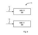
以上、処理回路70が第1受信パス30及び第2受信パス40からの出力信号を合成するように適合される実施形態を説明した。他の実施形態においては、処理回路70は、非CAモードにおいて、第1受信パス30の出力信号及び第2受信パス40の出力信号を別々に処理することにより、第1の処理後信号及び第2の処理後信号をそれぞれ生成する、ように構成される。これが図8に例示される。図中、処理回路70は、第1受信パス30からの出力信号を別個に処理するように構成される第1処理パス350と、第2受信パス40からの出力信号を別個に処理するように構成される第2処理パス360と、を含む。受信パスからの出力信号の処理は、この文脈では、例えば、等化、復調、及び復号等の周知の動作を含み得るが、それらに限定されない。当該処理は、信号強度の測定を行うことも含み得る。これについて以下にさらに説明する。
The embodiment has been described above in which the
いくつかの状況では、所望の信号の電力は不明である。このような状況の一例は、端末1が測定を実行する場合である。例えば、端末1は、サービングセルに接続され得るが、例えばハンドオーバのために又はSCellとして使用するために好適なターゲットセルの特定を容易にするために、近隣セルに対して周期的に測定を行い得る。受信パスの所与の利得設定に対して、受信パスは、何らかのダイナミックレンジを、即ち、取り扱い可能な入力信号電力レベルの範囲を有する。ダイナミックレンジの下限閾値よりも低い入力信号電力レベルについては、信号は、受信パスにおける雑音及び他の望まれない信号成分に隠れてしまうであろう。ダイナミック入力レンジの上限閾値よりも高い入力信号電力レベルについては、信号は、受信パスにおいて飽和し又はクリップされるであろう。ダイナミックレンジは、受信パスの利得設定に依存する。利得が大きくなれば、受信パスはより低い入力信号電力レベルを扱うことができるが、同時に、より低い入力信号電力レベルでクリップ又は飽和が始まってしまう。
In some situations, the power of the desired signal is unknown. An example of such a situation is when the
上述のような、所望の信号の電力が不明な状況では、第1受信パス30及び第2受信パス40のために異なる利得設定を選択し、第1受信パス30からの出力信号と第2受信パス40からの出力信号とを別々に処理することによって、無線受信機回路10のダイナミックレンジを増大させることができる。異なる利得設定を使用することにより、あり得る入力信号電力レベルのうち、単一の受信パスがカバーするであろう範囲よりもより大きな範囲を、それら2つの受信パス30及び40が共同でカバーする。
In the situation where the power of the desired signal is unknown as described above, different gain settings are selected for the
例示の目的で、第1受信パス30の利得が第2受信パス40の利得よりも高く設定され(但し、いくつかの実施形態では逆もあり得る)、且つ、受信パス30及び40の双方によって取り扱い可能な入力信号電力レベルの重複範囲があるように第1受信パス30及び第2受信パス40のダイナミックレンジが部分的に重複しているケースを考える。この場合、その重複範囲の下に、第2受信パス40によって取り扱い可能ではないが第1受信パス30によって取り扱い可能な、入力信号電力レベルの下方範囲が存在する。その重複範囲の上に、第1受信パス30によって取り扱い可能ではないが第2受信パス40によって取り扱い可能な、入力信号電力レベルの上方範囲も存在する。この場合、第1受信パス30及び第2受信パス40の組み合わされたダイナミックレンジは、下方範囲と、重複範囲と、上方範囲と、の集合体となる(これは、第1受信パス30及び第2受信パス40のダイナミックレンジの集合体である)。この、組み合わされたダイナミックレンジは、個々の第1受信パス30のダイナミックレンジ及び第2受信パス40のダイナミックレンジよりも大きい。
For illustrative purposes, the gain of the first receive
したがって、いくつかの実施形態において、制御ユニット50は、非CAモードにおいて、第1受信パス及び第2受信パスが双方とも同じ単一のCC6を受信するように制御される際に、第1受信パス30及び第2受信パス40のうちの一方のパスの利得を第1受信パス30及び第2受信パス40のうちの他方のパスの利得よりも高くなるように制御する、ように適合される。いくつかの実施形態において、制御ユニット50は、受信パス30、40のうちの一方のパスの利得を可能な限り最も高い利得に設定し、及び、受信パス30、40のうちの他方のパスの利得を可能な限り最も低い利得に設定することにより、このように2つの受信パスを使用した場合に利用可能となる、達成可能な最大のダイナミックレンジを提供する、ように適合され得る。
Thus, in some embodiments, the
比較のために、信号強度の測定を行うために単一の受信パスを使用することを考える。そのケースでは、受信パスの初期の利得設定及び入力信号電力レベルによっては、信頼できる測定を行うために十分な利得設定を見つけ出す目的で、利得を繰り返し調整する必要があるかもしれず、よって、そうした測定は比較的遅い可能性がある。代わりに、2つの受信パスを、上述のように異なる利得設定で同時に使用すれば、増大されたダイナミックレンジにより、測定速度の向上が容易になり、利得調整の必要はたとえあったとしても少なくなる。例えば、受信パス30及び40のうちの一方のパスの利得が可能な限り最大の利得に設定され、受信パス30及び40のうちの他方のパスの利得が可能な限り最小の利得に設定されれば、それらの組み合わされたダイナミックレンジにより、単一の受信パスで検出可能ないずれの信号電力レベルの入力信号も、利得調整を何ら繰り返す必要なく、受信パス30及び40のうち少なくとも一方が正しく検出することができるようになる(但し、受信パス30及び40のいずれもが入力信号を正しく検出することができない中間の入力信号電力レベルが存在することがないように、受信パス30及び40の個々のダイナミックレンジが重なっていることを条件とする)。このような利得設定について、測定は、単一の受信パスを使用するよりも格段に速く実行されることができる。
For comparison, consider using a single receive path to make signal strength measurements. In that case, depending on the initial gain setting of the receive path and the input signal power level, it may be necessary to adjust the gain repeatedly in order to find a sufficient gain setting to make a reliable measurement. May be relatively slow. Instead, if two receive paths are used simultaneously with different gain settings as described above, the increased dynamic range makes it easier to improve measurement speed and reduces the need for gain adjustment, if any. . For example, the gain of one of the
セルラー通信システムにおいて、近隣セルについての測定は、所謂圧縮モードで実行されることができる。圧縮モードでは、サービスしている基地局から端末への送信が行われることのない測定ギャップを挟んで、信号送信がスケジューリングされる。このような測定ギャップ期間中、端末は、近隣セルに対して測定を行うことを可能にされる。上述のように測定の速度を上げることにより、端末は、他のやり方で可能であったであろうよりも短い測定ギャップ期間中に測定を完了することができ、よって、測定ギャップの持続期間を短縮し且つ圧縮モード期間中により多くのデータを送信することができるであろう。代替的に、測定ギャップの持続期間が短縮されない場合には、各測定ギャップ期間中により多くの測定を行うことができるようになる。さらに、向上した測定速度を利用して、非CAモードにおけるさらなる受信期間中に使用されるべき適正な利得設定を迅速に決定することが可能になる。 In cellular communication systems, measurements for neighboring cells can be performed in a so-called compressed mode. In the compressed mode, signal transmission is scheduled across a measurement gap in which transmission from the serving base station to the terminal is not performed. During such a measurement gap period, the terminal is enabled to perform measurements on neighboring cells. By increasing the speed of the measurement as described above, the terminal can complete the measurement during a shorter measurement gap than would otherwise be possible, thus reducing the duration of the measurement gap. It would be possible to shorten and send more data during the compressed mode. Alternatively, if the duration of the measurement gap is not shortened, more measurements can be made during each measurement gap period. Furthermore, the improved measurement speed can be utilized to quickly determine the proper gain setting to be used during further reception periods in non-CA mode.
したがって、いくつかの実施形態において、処理回路70は、第1受信パス30からの出力信号に対して及び第2受信パス40からの出力信号に対して信号強度測定を実行するように構成される。例えば、処理回路70は、第1受信パス30からの出力信号に対して及び第2受信パス40からの出力信号に対して信号強度測定を実行して、非CAモードにおけるさらなる受信期間中に使用されるべき利得設定を決定する、ように構成され得る。処理回路70は、決定された利得設定を制御ユニット50へ通信するように適合され得る。制御ユニット50は、非CAモードにおけるさらなる受信期間中に、決定された利得設定を適用するように、第1受信パス30及び/又は第2受信パス40を制御する、ように適合され得る。いくつかの実施形態において、非CAモードにおけるさらなる受信期間中に、決定された利得設定を適用することは、その決定された利得設定を初期の利得設定として適用すること、を意味する。その後、非CAモードにおけるさらなる受信期間中に、例えば変動する受信条件に対応するために、自動利得制御(AGC)アルゴリズムを使用して、利得設定をさらに調整することができる。AGCアルゴリズムは無線受信機設計の技術分野においてよく知られており、本明細書でこれ以上さらに詳細には説明されない。
Accordingly, in some embodiments, the
以上、非CAモードにおいて、第1処理パス30及び第2処理パス40からの出力信号を合成するように処理回路70が構成されるいくつかの実施形態を説明した。さらに、非CAモードにおいて、第1処理パス30及び第2処理パス40からの出力信号を別々に処理するように処理回路70が構成される他の実施形態を説明した。さらにいくつかの実施形態において、処理回路70は、双方を行うように構成される。例えば、非CAモードにおける第1の時間ピリオドの期間中、制御ユニット50は、第1受信パス30及び第2受信パス40のうちの一方のパスの利得を第1受信パス30及び第2受信パス40のうちの他方のパスの利得よりも高くなるように制御する、ように適合されることができ、処理回路70は、第1受信パス30及び第2受信パス40からの出力信号を別々に処理し、及び、信号強度測定を実行して、非CAモードにおけるさらなる受信期間中に使用されるべき利得設定を決定する、ように構成され得る。非CAモードにおける、上記第1の時間ピリオドの後の第2の時間ピリオドの期間中、制御ユニット50は、決定された利得設定を適用するように第1受信パス30及び/又は第2受信パス40を制御するように適合され、処理回路70は、第1受信パス30及び第2受信パスからの出力信号を合成するように適合され得る。いくつかの実施形態において、信号強度に依存して、制御ユニット50は、上記第2の時間ピリオドの期間中、電力を節約するために、受信パス30及び40のうちの一方を選択的に無効化するように適合され得る。
In the above, some embodiments have been described in which the
本発明のいくつかの実施形態によれば、無線受信機回路10を動作させる方法が提供される。方法は、CAモードにおいて、制御ユニット50により、複数のCC6、8のうちの第1CC6を受信するように第1受信パス30を制御し、及び、複数のCC6、8のうちの、第1CC6とは別個の第2CC8を受信するように第2受信パス40を制御すること、を含む。上記方法は、非CAモードにおいて、制御ユニット50により、同じ単一のCC6を双方が受信するように、第1受信パス30及び第2受信パス40を選択的に制御すること、をさらに含む。
In accordance with some embodiments of the present invention, a method for operating a
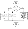
方法の一実施形態が、図9にフローチャートで例示される。動作は、ステップ400において開始される。ステップ410において、無線受信機回路10がCAモードで動作するのか非CAモードで動作するのかがチェックされる。CAモードで動作する場合(ステップ410からYESブランチ)、制御ユニット50は、ステップ420において、第1CC6を受信するように第1受信パス30を制御し、ステップ430において、第2CC8を受信するように第2受信パス40を制御する。方法の動作はその後ステップ440で終了する。無線受信機回路10が非CAモードで動作する場合(ステップ410からNOブランチ)、制御ユニット50は、ステップ450において、同じ単一のCC6を双方が受信するように第1受信パス30及び第2受信パス40を選択的に制御する。方法の動作はその後ステップ440で終了する。
One embodiment of the method is illustrated in flowchart form in FIG. Operation begins at
無線受信機回路10の実施形態の文脈で上述したように、同じ単一のCC6を双方が受信するように第1受信パス30及び第2受信パス40を選択的に制御することは、いくつかの実施形態では、(単一の受信パスを使用する場合と比べて)増大されたダイナミックレンジが必要とされる場合には第1受信パス30及び第2受信パス40を双方とも同じ単一のCC6を受信するように制御し、その他の場合には電力を節約するために第2受信パス40を無効化すること、を含むことができる。先に述べたように、増大されたダイナミックレンジが必要とされる可能性がある状況は、例えば、受信される信号が比較的弱い状況、障害となる干渉物が存在する状況、及び、受信される信号の強度が無線受信機回路10には当初不明である場合の信号測定期間中、である。図10は、ステップ450(図9)の一実施形態についてのフローチャートである。ステップ450の動作はステップ500において開始される。ステップ510において、増大されたダイナミックレンジが必要とされるかどうかが制御ユニット50によりチェックされる。もし必要とされれば(ステップ510からYESブランチ)、制御ユニット50は、同じ単一のCC6を双方が受信するように第1受信パス30及び第2受信パス40を制御する。その後、ステップ450の動作はステップ530において終了する。もし必要とされなければ(ステップ510からNOブランチ)、制御ユニット50は、電力を節約するために第2受信パス40を無効化する。その後、ステップ450の動作はステップ530において終了する。
As described above in the context of the embodiment of the
本発明の実施形態は、CA動作期間中に複数のCCを受信するために意図された回路を効率的に再使用することにより、非CA動作期間中の無線受信機回路のダイナミックレンジを増強するためのケイパビリティを提供する。ダイナミックレンジの増強を提供するために、CA動作を使用して複数のCCを受信することが意図されている回路を再使用することは、例えば、ダイナミックレンジの増強を提供するために、例えばハードウェアの観点から比較的少量のオーバヘッドしか必要とされない、という点で有利である。 Embodiments of the present invention enhance the dynamic range of a radio receiver circuit during non-CA operation by efficiently reusing the circuit intended to receive multiple CCs during CA operation. Providing capabilities for Reusing a circuit that is intended to receive multiple CCs using CA operation to provide dynamic range enhancement, for example, to provide dynamic range enhancement, for example hard This is advantageous in that a relatively small amount of overhead is required from the wear point of view.
いくつかの実施形態では、制御ユニット50は、専用の特定用途向けハードウェアユニットとして実装され得る。代替的に、制御ユニット50又はその複数の部分は、1つ以上のフィールドプログラマブルゲートアレイ(FPGA)、プロセッサ、又はマイクロコントローラ等の、但しそれらに限定されない、プログラム可能な及び/又は構成可能なハードウェアユニットで実装され得る。よって、制御ユニット50は、プログラム可能な制御ユニットであり得る。このため、本発明の実施形態は、本明細書において説明される方法及び機能の実現を可能にするコンピュータプログラムプロダクトに組み込まれ得る。したがって、本発明の実施形態によれば、方法の実施形態のいずれかにおけるステップ群をプログラム可能な制御ユニットに実行させるように構成される命令を含む、コンピュータプログラムプロダクト、が提供される。コンピュータプログラムプロダクトは、図11に示されるようなコンピュータ読取可能な媒体600に記憶されるプログラムコードを含み得る。プログラムコードは、方法の実施形態のいずれかにおけるステップ群をプログラム可能な制御ユニットに実行させるために、そのプログラム可能な制御ユニットによってロードされ及び実行されることができる。コンピュータ読取可能な媒体600は、例えば、非一時的なコンピュータ読取可能な媒体であり得る。
In some embodiments, the
以上、本発明を具体的な実施形態を参照して説明した。しかしながら、上述のものとは別の実施形態も発明の範囲内で可能である。ハードウェア又はソフトウェアによって方法を実行する、上述のものとは異なる方法ステップが発明の範囲内で提供されてもよい。実施形態の様々な特徴及びステップが上記したものとは別の組み合わせで組み合わせられてもよい。発明の範囲は、添付の特許請求の範囲によってのみ限定される。
The present invention has been described above with reference to specific embodiments. However, other embodiments than those described above are possible within the scope of the invention. Different method steps than those described above, performing the method by hardware or software, may be provided within the scope of the invention. Various features and steps of the embodiments may be combined in other combinations than those described above. The scope of the invention is limited only by the appended claims.
Claims (18)
アンテナ(15)へ動作可能に接続されるように構成される第1受信パス(30)と、
同じ前記アンテナ(15)へ動作可能に接続されるように構成される第2受信パス(40)と、
前記第1受信パス(30)及び前記第2受信パス(40)へ動作可能に接続される制御ユニット(50)と、
を含み、
前記制御ユニット(50)は、前記CAモードにおいて、前記複数のCCのうちの第1CC(6)を受信するように前記第1受信パス(30)を制御し、及び、前記複数のCCのうちの前記第1CC(6)とは別個の第2CC(8)を受信するように前記第2受信パスを制御する、ように適合され、
前記制御ユニット(50)は、前記非CAモードにおいて、同じ前記単一のCC(6)を双方が受信するように、前記第1受信パス(30)及び前記第2受信パス(40)を選択的に制御する、ように適合される、
無線受信機回路(10)。 A radio receiver circuit (10) configured to receive a plurality of component carriers (CC) (6, 8), configurable to operate in a carrier aggregation (CA) mode, wherein in a non-CA mode: The radio receiver circuit (10) is to receive a single CC (6),
A first receive path (30) configured to be operably connected to an antenna (15);
A second receive path (40) configured to be operatively connected to the same antenna (15);
A control unit (50) operatively connected to the first reception path (30) and the second reception path (40);
Including
The control unit (50) controls the first reception path (30) so as to receive a first CC (6) of the plurality of CCs in the CA mode, and among the plurality of CCs Adapted to control the second receive path to receive a second CC (8) separate from the first CC (6) of
The control unit (50) selects the first reception path (30) and the second reception path (40) so that both receive the same single CC (6) in the non-CA mode. Adapted to control,
Radio receiver circuit (10).
前記第2受信パス(40)は、第2LO信号で駆動されるように構成されるミキサユニット(200)を含み、
前記制御ユニット(50)は、前記CAモードにおいて、前記第1受信パス(30)による前記第1CC(6)の受信を可能にするために前記第1LO信号の周波数を制御し、及び、前記第2受信パスによる前記第2CC(8)の受信を可能にするために前記第2LO信号の周波数を制御する、ように適合される、
請求項1又は2に記載の無線受信機回路(10)。 The first receive path (30) includes a mixer unit (100) configured to be driven by a first local oscillator (LO) signal;
The second receive path (40) includes a mixer unit (200) configured to be driven by a second LO signal,
The control unit (50) controls a frequency of the first LO signal to enable reception of the first CC (6) by the first reception path (30) in the CA mode; and Adapted to control the frequency of the second LO signal to enable reception of the second CC (8) by two receive paths;
Radio receiver circuit (10) according to claim 1 or 2.
前記無線受信機回路(10)の前記第1受信パス及び前記第2受信パスの双方が動作可能に接続されるアンテナ(15)と、
を含む、無線通信装置(1)。 A wireless receiver circuit (10) according to any of the preceding claims;
An antenna (15) to which both the first reception path and the second reception path of the wireless receiver circuit (10) are operatively connected;
A wireless communication device (1).
アンテナ(15)へ動作可能に接続される第1受信パス(30)と、
同じ前記アンテナ(15)へ動作可能に接続される第2受信パス(40)と、
前記第1受信パス(30)及び前記第2受信パス(40)へ動作可能に接続される制御ユニット(50)と、
を含み、
前記方法は、
前記CAモードにおいて、前記制御ユニット(50)により、前記複数の周波数帯域(6,8)のうちの第1CC(6)を受信するように前記第1受信パス(30)を制御し、及び、前記複数のCC(6,8)のうちの前記第1CC(6)とは別個の第2CC(8)を受信するように前記第2受信パス(40)を制御すること(420,430)と、
前記非CAモードにおいて、前記制御ユニット(50)により、同じ前記単一のCC(6)を双方が受信するように、前記第1受信パス(30)及び前記第2受信パス(40)を選択的に制御すること(450)と、
を含む、方法。 A method of operating a radio receiver circuit (10) configured to receive a plurality of component carriers (CC) (6, 8), configured to operate in a carrier aggregation (CA) mode, comprising: In CA mode, the radio receiver circuit (10) is to receive a single frequency CC (6), and the radio receiver circuit (10)
A first receive path (30) operatively connected to the antenna (15);
A second receive path (40) operatively connected to the same antenna (15);
A control unit (50) operatively connected to the first reception path (30) and the second reception path (40);
Including
The method
In the CA mode, the control unit (50) controls the first reception path (30) to receive the first CC (6) of the plurality of frequency bands (6, 8), and Controlling the second reception path (40) to receive a second CC (8) separate from the first CC (6) of the plurality of CCs (6, 8) (420, 430); ,
In the non-CA mode, the control unit (50) selects the first reception path (30) and the second reception path (40) so that both receive the same single CC (6). Controlling (450) automatically,
Including a method.
Computer stored with a computer program product comprising computer program code for performing the method according to claim 16, when executed by the control unit (50) of the radio receiver circuit (10). A readable medium (600).
Applications Claiming Priority (1)
| Application Number | Priority Date | Filing Date | Title |
|---|---|---|---|
| PCT/EP2014/069280 WO2016037649A1 (en) | 2014-09-10 | 2014-09-10 | Radio receiver for carrier aggregation |
Publications (2)
| Publication Number | Publication Date |
|---|---|
| JP2017531379A JP2017531379A (en) | 2017-10-19 |
| JP6307662B2 true JP6307662B2 (en) | 2018-04-04 |
Family
ID=51535429
Family Applications (1)
| Application Number | Title | Priority Date | Filing Date |
|---|---|---|---|
| JP2017513536A Expired - Fee Related JP6307662B2 (en) | 2014-09-10 | 2014-09-10 | Radio receiver for carrier aggregation |
Country Status (17)
| Country | Link |
|---|---|
| US (3) | US9344318B2 (en) |
| EP (2) | EP3355478B1 (en) |
| JP (1) | JP6307662B2 (en) |
| KR (2) | KR101866707B1 (en) |
| CN (1) | CN106688187B (en) |
| AU (2) | AU2014405866B2 (en) |
| BR (1) | BR112017003677A2 (en) |
| CA (1) | CA2960736C (en) |
| DK (2) | DK3355478T3 (en) |
| ES (2) | ES2754790T3 (en) |
| HU (1) | HUE037929T2 (en) |
| IL (1) | IL250669A (en) |
| MX (1) | MX366605B (en) |
| MY (1) | MY191230A (en) |
| PL (2) | PL3192179T3 (en) |
| RU (1) | RU2657244C1 (en) |
| WO (1) | WO2016037649A1 (en) |
Families Citing this family (12)
| Publication number | Priority date | Publication date | Assignee | Title |
|---|---|---|---|---|
| HUE037929T2 (en) | 2014-09-10 | 2018-09-28 | Ericsson Telefon Ab L M | Radio receiver for carrier aggregation |
| US9755767B2 (en) * | 2014-10-31 | 2017-09-05 | Qualcomm Incorporated | Mechanism to measure, report, and allocate a highest possible rank for each cell in a carrier aggregation (CA) mode receiver-limited user equipment (UE) |
| US10263754B2 (en) * | 2015-09-21 | 2019-04-16 | Qualcomm Incorporated | Wireless device architecture to support very-high-reliability (VHR) communication |
| US10574278B2 (en) * | 2015-11-13 | 2020-02-25 | Texas Instruments Incorporated | High dynamic range ask wake-up receiver |
| US10389456B2 (en) | 2016-08-26 | 2019-08-20 | Texas Instruments Incorporated | Wake up receiver using multiphase peak detector and demodulator |
| JP6910441B2 (en) * | 2016-12-02 | 2021-07-28 | 華為技術有限公司Huawei Technologies Co.,Ltd. | Operation mode switching method and user equipment |
| KR102631348B1 (en) | 2018-04-19 | 2024-01-31 | 삼성전자주식회사 | Wireless communcating device tranceiving signals by using carrier aggregation in multi input multi output system |
| WO2020005224A1 (en) * | 2018-06-27 | 2020-01-02 | Intel IP Corporation | Dynamic low if mechanism for blocker avoidance |
| KR102653890B1 (en) * | 2019-10-18 | 2024-04-02 | 삼성전자주식회사 | A Radio Frequency Integrated Chip supporting carrier aggregation and an wireless communication apparatus including the same |
| KR102653889B1 (en) * | 2019-10-18 | 2024-04-02 | 삼성전자주식회사 | A receiver supporting carrier aggregation and an wireless communication apparatus including the same |
| CN113691269B (en) * | 2021-08-30 | 2022-03-25 | 上海航天测控通信研究所 | Frequency point-variable high-sensitivity satellite measurement and control receiver |
| CN113872622B (en) * | 2021-10-15 | 2022-05-27 | 上海航天测控通信研究所 | Variable frequency point satellite measurement and control transmitter |
Family Cites Families (18)
| Publication number | Priority date | Publication date | Assignee | Title |
|---|---|---|---|---|
| US8363744B2 (en) * | 2001-06-10 | 2013-01-29 | Aloft Media, Llc | Method and system for robust, secure, and high-efficiency voice and packet transmission over ad-hoc, mesh, and MIMO communication networks |
| EP1944887B1 (en) | 2007-01-11 | 2013-11-06 | Harman Becker Automotive Systems GmbH | Radio receiver for hybrid broadcast systems |
| DE602008001789D1 (en) * | 2008-05-14 | 2010-08-26 | Ericsson Telefon Ab L M | Method for controlling a receiver gain |
| KR101347295B1 (en) * | 2010-11-02 | 2014-01-03 | 한국전자통신연구원 | Reception apparatus and Transmission apparatus for approving scalable bandwidth on the carrier aggregation environment |
| US9602145B2 (en) * | 2011-02-07 | 2017-03-21 | Qualcomm Incorporated | Insertion loss improvement in a multi-band device |
| US9252827B2 (en) * | 2011-06-27 | 2016-02-02 | Qualcomm Incorporated | Signal splitting carrier aggregation receiver architecture |
| US8892057B2 (en) * | 2011-08-23 | 2014-11-18 | Rf Micro Devices, Inc. | Carrier aggregation radio system |
| EP2590351A3 (en) * | 2011-11-04 | 2013-05-22 | ST-Ericsson SA | Non-contiguous carrier aggregation |
| US9532237B2 (en) * | 2012-03-15 | 2016-12-27 | Broadcom Corporation | Reducing complexity and power consumption in cellular networks with carrier aggregation |
| GB2500265B (en) * | 2012-03-16 | 2014-03-05 | Broadcom Corp | Reconfigurable radio frequency circuits and methods of receiving |
| CN103517401A (en) * | 2012-06-29 | 2014-01-15 | 中兴通讯股份有限公司 | Wireless transmission method, device and system |
| US9813953B2 (en) * | 2012-07-04 | 2017-11-07 | Telefonaktiebolaget Lm Ericsson (Publ) | Radio network node, a user equipment and methods therein |
| TWI465050B (en) * | 2012-12-19 | 2014-12-11 | Ind Tech Res Inst | Receiver and transmitter apparatus for carrier aggregation |
| KR102180573B1 (en) * | 2013-10-22 | 2020-11-18 | 삼성전자주식회사 | Method for receiving signals and an electronic device |
| US9628163B2 (en) * | 2014-03-25 | 2017-04-18 | Marvell International Ltd. | Low-complexity communication terminal with enhanced receive diversity |
| US9681447B2 (en) * | 2014-05-15 | 2017-06-13 | Qualcomm Incorporated | Dynamic local oscillator (LO) scheme and switchable receive (RX) chain for carrier aggregation |
| US9712226B2 (en) * | 2014-05-15 | 2017-07-18 | Qualcomm Incorporated | Multi-way diversity receiver with multiple synthesizers in a carrier aggregation transceiver |
| HUE037929T2 (en) * | 2014-09-10 | 2018-09-28 | Ericsson Telefon Ab L M | Radio receiver for carrier aggregation |
-
2014
- 2014-09-10 HU HUE14761994A patent/HUE037929T2/en unknown
- 2014-09-10 EP EP18154125.1A patent/EP3355478B1/en active Active
- 2014-09-10 CN CN201480081831.4A patent/CN106688187B/en not_active Expired - Fee Related
- 2014-09-10 JP JP2017513536A patent/JP6307662B2/en not_active Expired - Fee Related
- 2014-09-10 US US14/768,380 patent/US9344318B2/en active Active
- 2014-09-10 AU AU2014405866A patent/AU2014405866B2/en not_active Ceased
- 2014-09-10 ES ES18154125T patent/ES2754790T3/en active Active
- 2014-09-10 MY MYPI2017700690A patent/MY191230A/en unknown
- 2014-09-10 MX MX2017003081A patent/MX366605B/en active IP Right Grant
- 2014-09-10 BR BR112017003677A patent/BR112017003677A2/en active Search and Examination
- 2014-09-10 DK DK18154125T patent/DK3355478T3/en active
- 2014-09-10 CA CA2960736A patent/CA2960736C/en active Active
- 2014-09-10 KR KR1020177009670A patent/KR101866707B1/en active IP Right Grant
- 2014-09-10 ES ES14761994.4T patent/ES2671558T3/en active Active
- 2014-09-10 WO PCT/EP2014/069280 patent/WO2016037649A1/en active Application Filing
- 2014-09-10 KR KR1020187015374A patent/KR102063564B1/en active IP Right Grant
- 2014-09-10 DK DK14761994.4T patent/DK3192179T3/en active
- 2014-09-10 PL PL14761994T patent/PL3192179T3/en unknown
- 2014-09-10 RU RU2017111650A patent/RU2657244C1/en active
- 2014-09-10 PL PL18154125T patent/PL3355478T3/en unknown
- 2014-09-10 EP EP14761994.4A patent/EP3192179B1/en active Active
-
2016
- 2016-04-25 US US15/137,669 patent/US10014824B2/en active Active
-
2017
- 2017-02-19 IL IL250669A patent/IL250669A/en active IP Right Grant
-
2018
- 2018-02-26 AU AU2018201359A patent/AU2018201359B2/en not_active Ceased
- 2018-06-01 US US15/995,811 patent/US10326403B2/en not_active Expired - Fee Related
Also Published As
Similar Documents
| Publication | Publication Date | Title |
|---|---|---|
| JP6307662B2 (en) | Radio receiver for carrier aggregation | |
| US20180241458A1 (en) | Network discovery and beam acquisition in 5g rat beam cell operation | |
| US11611939B2 (en) | Techniques for determining power offsets of a physical downlink shared channel | |
| GB2514574A (en) | Method, apparatus and computer program for search and synchronisation | |
| US9557407B1 (en) | Radar detection for adjacent segments in wireless communications | |
| EP3370468A1 (en) | Enhanced overlaid code division multiple access (cdma) | |
| WO2017105407A1 (en) | Signal structure for full-duplex cellular systems | |
| JP2016019192A (en) | Radio communication device and radio communication method | |
| WO2018031583A1 (en) | Method of heterogeneous brs transmission in nr | |
| RU2710538C2 (en) | Radio beacon for carrier aggregation | |
| OA20931A (en) | Radio receiver carrier aggregation | |
| CN107211359B (en) | Apparatus, method and computer readable medium for scanning frequency band | |
| KR102065020B1 (en) | Apparatus and method for obtaining synchronization in wireless communication system | |
| WO2014163545A1 (en) | Apparatus and method for receiving a primary and a secondary carrier |
Legal Events
| Date | Code | Title | Description |
|---|---|---|---|
| A977 | Report on retrieval |
Free format text: JAPANESE INTERMEDIATE CODE: A971007 Effective date: 20180226 |
|
| TRDD | Decision of grant or rejection written | ||
| A01 | Written decision to grant a patent or to grant a registration (utility model) |
Free format text: JAPANESE INTERMEDIATE CODE: A01 Effective date: 20180306 |
|
| A61 | First payment of annual fees (during grant procedure) |
Free format text: JAPANESE INTERMEDIATE CODE: A61 Effective date: 20180312 |
|
| R150 | Certificate of patent or registration of utility model |
Ref document number: 6307662 Country of ref document: JP Free format text: JAPANESE INTERMEDIATE CODE: R150 |
|
| R250 | Receipt of annual fees |
Free format text: JAPANESE INTERMEDIATE CODE: R250 |
|
| R250 | Receipt of annual fees |
Free format text: JAPANESE INTERMEDIATE CODE: R250 |
|
| LAPS | Cancellation because of no payment of annual fees |