JP6306174B2 - Improved receiver alias removal by adding an offset - Google Patents
Improved receiver alias removal by adding an offset Download PDFInfo
- Publication number
- JP6306174B2 JP6306174B2 JP2016526985A JP2016526985A JP6306174B2 JP 6306174 B2 JP6306174 B2 JP 6306174B2 JP 2016526985 A JP2016526985 A JP 2016526985A JP 2016526985 A JP2016526985 A JP 2016526985A JP 6306174 B2 JP6306174 B2 JP 6306174B2
- Authority
- JP
- Japan
- Prior art keywords
- signal
- channel
- offset
- frequency
- downconverted
- Prior art date
- Legal status (The legal status is an assumption and is not a legal conclusion. Google has not performed a legal analysis and makes no representation as to the accuracy of the status listed.)
- Expired - Fee Related
Links
Images


Classifications
-
- G—PHYSICS
- G01—MEASURING; TESTING
- G01S—RADIO DIRECTION-FINDING; RADIO NAVIGATION; DETERMINING DISTANCE OR VELOCITY BY USE OF RADIO WAVES; LOCATING OR PRESENCE-DETECTING BY USE OF THE REFLECTION OR RERADIATION OF RADIO WAVES; ANALOGOUS ARRANGEMENTS USING OTHER WAVES
- G01S19/00—Satellite radio beacon positioning systems; Determining position, velocity or attitude using signals transmitted by such systems
- G01S19/01—Satellite radio beacon positioning systems transmitting time-stamped messages, e.g. GPS [Global Positioning System], GLONASS [Global Orbiting Navigation Satellite System] or GALILEO
- G01S19/13—Receivers
- G01S19/21—Interference related issues ; Issues related to cross-correlation, spoofing or other methods of denial of service
-
- G—PHYSICS
- G01—MEASURING; TESTING
- G01S—RADIO DIRECTION-FINDING; RADIO NAVIGATION; DETERMINING DISTANCE OR VELOCITY BY USE OF RADIO WAVES; LOCATING OR PRESENCE-DETECTING BY USE OF THE REFLECTION OR RERADIATION OF RADIO WAVES; ANALOGOUS ARRANGEMENTS USING OTHER WAVES
- G01S19/00—Satellite radio beacon positioning systems; Determining position, velocity or attitude using signals transmitted by such systems
- G01S19/01—Satellite radio beacon positioning systems transmitting time-stamped messages, e.g. GPS [Global Positioning System], GLONASS [Global Orbiting Navigation Satellite System] or GALILEO
- G01S19/13—Receivers
- G01S19/24—Acquisition or tracking or demodulation of signals transmitted by the system
-
- H—ELECTRICITY
- H04—ELECTRIC COMMUNICATION TECHNIQUE
- H04B—TRANSMISSION
- H04B1/00—Details of transmission systems, not covered by a single one of groups H04B3/00 - H04B13/00; Details of transmission systems not characterised by the medium used for transmission
- H04B1/69—Spread spectrum techniques
- H04B1/707—Spread spectrum techniques using direct sequence modulation
- H04B1/7097—Interference-related aspects
Landscapes
- Engineering & Computer Science (AREA)
- Radar, Positioning & Navigation (AREA)
- Remote Sensing (AREA)
- Computer Networks & Wireless Communication (AREA)
- Physics & Mathematics (AREA)
- General Physics & Mathematics (AREA)
- Signal Processing (AREA)
- Position Fixing By Use Of Radio Waves (AREA)
- Noise Elimination (AREA)
Description
[0001]本発明は、一般に、モバイルデバイス上の受信機エイリアス除去(receiver alias rejection)に関する。本開示の態様は、オフセットを追加することによって受信機エイリアス除去を改善するための方法に関する。詳細には、エイリアス除去を改善するためにGNSS信号を処理するための様々な技法が提供される。 [0001] The present invention relates generally to receiver alias rejection on mobile devices. Aspects of the disclosure relate to a method for improving receiver alias removal by adding an offset. In particular, various techniques are provided for processing GNSS signals to improve alias removal.
[0002]エイリアシングは、異なる信号がサンプリングされるときに識別不可能になる効果を指す。不要な信号はエイリアス化信号(aliased signal)またはイメージ化信号(imaged signal)として知られ得る。エイリアス除去は、不要なエイリアス化信号またはイメージ化信号を除去する方法を指す。エイリアス除去の1つの方法はコード分離である。たとえば、現在のGPS受信機は、正の周波数における衛星チャネルと負の周波数における衛星チャネルとを識別するためにコード分離を使用することができる。 [0002] Aliasing refers to the effect of becoming indistinguishable when different signals are sampled. The unwanted signal can be known as an aliased signal or an imaged signal. Alias removal refers to a method of removing unwanted aliased or imaged signals. One method of alias removal is code separation. For example, current GPS receivers can use code separation to distinguish between satellite channels at positive frequencies and satellite channels at negative frequencies.
[0003]オフセットを追加することによって受信機エイリアス除去を改善することができるいくつかの実施形態について説明する。 [0003] Several embodiments are described that can improve receiver alias removal by adding an offset.
[0004]同じコードをもつ複数のGNSS信号から所望のGNSS信号を分離するための方法、システム、コンピュータ可読媒体、および装置が提示される。いくつかの実施形態では、方法は、モバイルデバイスによって複数のGNSS信号を受信すること、ここにおいて、複数のGNSS信号が所望のGNSS信号を含む、を備え得る。その後、本方法は、受信された複数のGNSS信号をダウンコンバートされた信号に処理すること、ここにおいて、ダウンコンバートされた信号が所望のGNSS信号よりも低い周波数を有し、ここにおいて、ダウンコンバートされた信号が、非0周波数に関連する第1のチャネルを含む、を備え得る。その上、本方法は、オフセットされたダウンコンバートされた信号を作成するために第1のチャネルの分数に対応するオフセット周波数だけ第1のチャネルをオフセットするように、ダウンコンバートされた信号を処理することを備え得る。さらに、本方法は、オフセット周波数に基づいて、オフセットされたダウンコンバートされた信号から所望のGNSS信号を決定することを備え得る。 [0004] Methods, systems, computer-readable media, and apparatus are presented for separating a desired GNSS signal from multiple GNSS signals having the same code. In some embodiments, the method may comprise receiving a plurality of GNSS signals by a mobile device, wherein the plurality of GNSS signals include a desired GNSS signal. The method then processes the received GNSS signals into a downconverted signal, where the downconverted signal has a lower frequency than the desired GNSS signal, where the downconverted signal The signal comprising a first channel associated with a non-zero frequency. Moreover, the method processes the downconverted signal to offset the first channel by an offset frequency corresponding to a fraction of the first channel to create an offset downconverted signal. You can prepare for that. Further, the method can comprise determining a desired GNSS signal from the offset downconverted signal based on the offset frequency.
[0005]たとえば、GLONASSは、共通コードをもつGNSS信号の一例であり得る。さらに、共通コードをもつGNSS信号は異なる周波数においてブロードキャストされ得、ただし、各信号は異なる衛星からのものである。さらに、各衛星は異なる周波数において動作していることがある(たとえば、各衛星の信号は異なる周波数にある)。 [0005] For example, GLONASS may be an example of a GNSS signal with a common code. Furthermore, GNSS signals with a common code can be broadcast on different frequencies, where each signal is from a different satellite. In addition, each satellite may be operating at a different frequency (eg, each satellite's signal is at a different frequency).
[0006]少なくとも1つの構成では、決定することは、オフセットされたダウンコンバートされた信号を逆拡散すること、ここにおいて、オフセットされたダウンコンバートされた信号が、第1のチャネルに関連するエイリアス化信号を含む、と、オフセット周波数に基づいてエイリアス信号をフィルタで除去することによってエイリアス化信号を除去することと、をさらに備え得る。 [0006] In at least one configuration, the determining comprises despreading the offset downconverted signal, wherein the offset downconverted signal is aliased with respect to the first channel. And further comprising removing the aliased signal by filtering out the aliased signal based on the offset frequency.
[0007]少なくとも1つの構成では、第1のチャネルは正の周波数であり、ダウンコンバートされた信号は0ヘルツまたはその近くを中心とし、ダウンコンバートされた信号は、負の周波数に関連する第2のチャネルをさらに含み、第1のチャネルをオフセットすることは、第1のチャネルの中心が第2のチャネルの中心からオフセットされることとなる。さらに、第1のチャネルに関連するエイリアス化信号の中心と、第2のチャネルに関連する所望のGNSS信号の中心とは、オフセット周波数に基づいてオフセットされる。 [0007] In at least one configuration, the first channel is at a positive frequency, the downconverted signal is centered at or near zero hertz, and the downconverted signal is a second frequency associated with a negative frequency. Further offsetting the first channel results in the center of the first channel being offset from the center of the second channel. Further, the center of the aliased signal associated with the first channel and the center of the desired GNSS signal associated with the second channel are offset based on the offset frequency.
[0008]代替的に、少なくとも1つの構成では、第1のチャネルは負の周波数であり、ダウンコンバートされた信号は0ヘルツまたはその近くを中心とし、ダウンコンバートされた信号は、正の周波数に関連する第2のチャネルをさらに含み、オフセットは、第1のチャネルの中心が第2のチャネルの中心からオフセットされることとなる。さらに、第1のチャネルに関連するエイリアス化信号の中心と、第2のチャネルに関連する所望のGNSS信号の中心とは、オフセット周波数に基づいてオフセットされる。 [0008] Alternatively, in at least one configuration, the first channel is at a negative frequency, the downconverted signal is centered at or near zero hertz, and the downconverted signal is at a positive frequency. Further comprising an associated second channel, the offset would be that the center of the first channel is offset from the center of the second channel. Further, the center of the aliased signal associated with the first channel and the center of the desired GNSS signal associated with the second channel are offset based on the offset frequency.
[0009]少なくとも1つの構成では、ダウンコンバートされた信号への受信されたGNSS信号の処理は、部分的に、所望の信号に等しい周波数をもつ局部発振器によって行われる。 [0009] In at least one configuration, processing of the received GNSS signal into a down-converted signal is performed in part by a local oscillator having a frequency equal to the desired signal.
[0010]少なくとも1つの構成では、オフセット周波数だけ第1のチャネルをオフセットするためのダウンコンバートされた信号の処理は、部分的にデジタル信号プロセッサまたは汎用プロセッサによって行われる。 [0010] In at least one configuration, processing of the downconverted signal to offset the first channel by an offset frequency is performed in part by a digital signal processor or a general purpose processor.
[0011]少なくとも1つの構成では、オフセット周波数は第1のチャネルの1/4である。 [0011] In at least one configuration, the offset frequency is ¼ of the first channel.
[0012]少なくとも1つの構成では、オフセット周波数は第1のチャネルの3/4である。 [0012] In at least one configuration, the offset frequency is 3/4 of the first channel.
[0013]少なくとも1つの構成では、オフセット周波数は第1のチャネルの1/8である。 [0013] In at least one configuration, the offset frequency is 1/8 of the first channel.
[0014]さらに、少なくとも1つの構成では、Nは整数であり、Channel_Spacingは、第1のチャネルに関連するチャネル間隔であり、オフセット周波数は、オフセット周波数=(1/4+N*1/2)*Channel_Spacingである。 [0014] Further, in at least one configuration, N is an integer, Channel_Spacing is the channel spacing associated with the first channel, and the offset frequency is offset frequency = (1/4 + N * 1/2) * Channel_Spacing It is.
[0015]さらに、少なくとも1つの構成では、オフセット周波数は、第1のチャネルに関連する1/2チャネルの倍数である分数オフセットである。 [0015] Further, in at least one configuration, the offset frequency is a fractional offset that is a multiple of a half channel associated with the first channel.
[0016]別の実施形態では、同じコードをもつ複数のGNSS信号から所望のGNSS信号を分離するためのデバイスが開示される。デバイスは、メモリと、1つまたは複数の無線周波数(RF:radio frequency)受信機と、1つまたは複数のプロセッサとを備え得る。1つまたは複数のRF受信機は、複数のGNSS信号を受信すること、ここにおいて、複数のGNSS信号が所望のGNSS信号を含む、と、受信された複数のGNSS信号をダウンコンバートされた信号に処理すること、ここにおいて、ダウンコンバートされた信号が所望のGNSS信号よりも低い周波数を有し、ここにおいて、ダウンコンバートされた信号が、非0周波数に関連する第1のチャネルを含む、と、を行い得る。1つまたは複数のプロセッサは、オフセットされたダウンコンバートされた信号を作成するために第1のチャネルの分数に対応するオフセット周波数だけ第1のチャネルをオフセットするように、ダウンコンバートされた信号を処理することと、オフセット周波数に基づいて、オフセットされたダウンコンバートされた信号から所望のGNSS信号を決定することと、を行うように構成され得る。 [0016] In another embodiment, a device for separating a desired GNSS signal from multiple GNSS signals having the same code is disclosed. The device may comprise a memory, one or more radio frequency (RF) receivers, and one or more processors. One or more RF receivers receive a plurality of GNSS signals, wherein the plurality of GNSS signals include a desired GNSS signal, and the received plurality of GNSS signals are converted to a down-converted signal. Processing, wherein the downconverted signal has a lower frequency than the desired GNSS signal, wherein the downconverted signal includes a first channel associated with a non-zero frequency; Can be done. One or more processors process the downconverted signal to offset the first channel by an offset frequency corresponding to a fraction of the first channel to create an offset downconverted signal. And determining a desired GNSS signal from the offset downconverted signal based on the offset frequency.
[0017]別の実施形態では、1つまたは複数の非一時的コンピュータ可読媒体は、同じコードをもつ複数のGNSS信号から所望のGNSS信号を分離するために、1つまたは複数のRFモジュールによって複数のGNSS信号を受信すること、ここにおいて、複数のGNSS信号が所望のGNSS信号を含む、と、1つまたは複数のRFモジュールによって、受信された複数のGNSS信号をダウンコンバートされた信号に処理すること、ここにおいて、ダウンコンバートされた信号が所望のGNSS信号よりも低い周波数を有し、ここにおいて、ダウンコンバートされた信号が、非0周波数に関連する第1のチャネルを含む、と、1つまたは複数のプロセッサによって、オフセットされたダウンコンバートされた信号を作成するために第1のチャネルの分数に対応するオフセット周波数だけ第1のチャネルをオフセットするように、ダウンコンバートされた信号を処理することと、1つまたは複数のプロセッサによって、オフセット周波数に基づいて、オフセットされたダウンコンバートされた信号から所望のGNSS信号を決定することと、を行うためのコンピュータ実行可能命令を記憶し得る。 [0017] In another embodiment, the one or more non-transitory computer readable media are transmitted by the one or more RF modules to separate the desired GNSS signal from the plurality of GNSS signals having the same code. A plurality of GNSS signals, wherein the plurality of GNSS signals include a desired GNSS signal, and the one or more RF modules process the received plurality of GNSS signals into a down-converted signal. Where the down-converted signal has a lower frequency than the desired GNSS signal, where the down-converted signal includes a first channel associated with a non-zero frequency. Or by a plurality of processors to create an offset downconverted signal Processing the downconverted signal to offset the first channel by an offset frequency corresponding to a fraction of the channel and by one or more processors to be offset downconverted based on the offset frequency. Determining a desired GNSS signal from the received signals and storing computer-executable instructions for performing.
[0018]別の実施形態では、同じコードをもつ複数のGNSS信号から所望のGNSS信号を分離するための装置、本装置は、複数のGNSS信号を受信するための手段、ここにおいて、複数のGNSS信号が所望のGNSS信号を含む、と、受信された複数のGNSS信号をダウンコンバートされた信号に処理するための手段、ここにおいて、ダウンコンバートされた信号が所望のGNSS信号よりも低い周波数を有し、ここにおいて、ダウンコンバートされた信号が、非0周波数に関連する第1のチャネルを含む、と、オフセットされたダウンコンバートされた信号を作成するために第1のチャネルの分数に対応するオフセット周波数だけ第1のチャネルをオフセットするように、ダウンコンバートされた信号を処理するための手段と、オフセット周波数に基づいて、オフセットされたダウンコンバートされた信号から所望のGNSS信号を決定するための手段と、を備え得る。 [0018] In another embodiment, an apparatus for separating a desired GNSS signal from a plurality of GNSS signals having the same code, the apparatus comprising means for receiving a plurality of GNSS signals, wherein a plurality of GNSS signals Means for processing a plurality of received GNSS signals into a downconverted signal, wherein the signal comprises a desired GNSS signal, wherein the downconverted signal has a lower frequency than the desired GNSS signal; Where the downconverted signal includes a first channel associated with a non-zero frequency, and an offset corresponding to a fraction of the first channel to create an offset downconverted signal Means for processing the downconverted signal to offset the first channel by frequency, and off Based on Tsu preparative frequency, means for determining a desired GNSS signals from the offset down-converted signal may comprise a.
[0019]本開示の態様が例として示される。添付の図では、同様の参照番号は同様の要素を示す。 [0019] Aspects of the present disclosure are shown by way of example. In the accompanying drawings, like reference numerals indicate like elements.
[0031]次に、本出願の一部を形成する、添付の図面に関していくつかの例示的な実施形態について説明する。本開示の1つまたは複数の態様が実装され得る、特定の実施形態について以下で説明するが、本開示の範囲または添付の特許請求の範囲の趣旨を逸脱することなく、他の実施形態が使用され得、様々な変更が行われ得る。 [0031] Several exemplary embodiments will now be described with reference to the accompanying drawings, which form a part of this application. Specific embodiments in which one or more aspects of the disclosure may be implemented are described below, but other embodiments may be used without departing from the scope of the disclosure or the scope of the appended claims. Various changes can be made.
[0032]GLONASS(GLO)は、全地球測位システム(GPS:Global Positioning System)に代替を提供し補完するGNSS(全地球ナビゲーション衛星システム)である。すべてのGLONASS衛星は同じ標準精度信号を送信するが、各衛星は異なる周波数で送信する。GPS衛星とは異なり、GLO衛星はすべての衛星信号上で同じ符号分割多元接続(CDMA)拡散コードを有する。コードチップレートは511kHzであり、コードは511チップごとに繰り返す。各GLO衛星は1つのチャネルを有することができ、各衛星に関連するコードは同じである。各衛星に関連するチャネルのための周波数は異なることができる。 [0032] GLONASS (GLO) is a GNSS (Global Navigation Satellite System) that provides and complements the Global Positioning System (GPS). All GLONASS satellites transmit the same standard precision signal, but each satellite transmits at a different frequency. Unlike GPS satellites, GLO satellites have the same code division multiple access (CDMA) spreading code on all satellite signals. The code chip rate is 511 kHz, and the code repeats every 511 chips. Each GLO satellite can have one channel and the codes associated with each satellite are the same. The frequency for the channel associated with each satellite can be different.
[0033]その結果、正の周波数のためのGLOコードと負の周波数のためのGLOコードとは同じである。したがって、第1のGLO衛星のプラスチャネル(たとえば、正の周波数)が第2のGLO衛星のネガティブチャネル(たとえば、負の周波数)の上に被さるとき、コード分離の方法はエイリアス除去に役立つことができない。 [0033] As a result, the GLO code for positive frequencies and the GLO code for negative frequencies are the same. Thus, when the first GLO satellite's positive channel (eg, positive frequency) is overlaid on the second GLO satellite's negative channel (eg, negative frequency), the code separation method can help with alias removal. Can not.
[0034]主に、GNSS受信機は、信号の同相(I)バージョンと直交位相(Q)バージョンとを生成することによって信号を直交形式で表すことによって、信号とエイリアス信号とを別々に区別する。この種のシステムにおけるエイリアス除去の量は、I成分とQ成分との表現の精度に依存し、これは、受信機の処理セクションが、信号とエイリアス信号とを互いに確実に区別し得るために十分でないことがある。信号に関する信号データを見ることによって、または衛星の長期トラッキングによって、信号をエイリアス信号と区別するためのいくつかの他の処理方法がある。しかしながら、これらの処理方法は時間がかかり、高い計算能力を必要とする。したがって、エイリアス除去を改善することは、信号を区別するためのより効率的な方法であり得る。 [0034] Primarily, the GNSS receiver distinguishes between signals and alias signals separately by representing the signals in quadrature form by generating in-phase (I) and quadrature (Q) versions of the signal. . The amount of antialiasing in this type of system depends on the accuracy of the representation of the I and Q components, which is sufficient to ensure that the processing section of the receiver can distinguish the signal and the alias signal from each other. It may not be. There are several other processing methods for distinguishing signals from alias signals by looking at signal data about the signal or by long-term tracking of the satellite. However, these processing methods are time consuming and require high computing power. Thus, improving anti-aliasing can be a more efficient way to distinguish signals.
[0035]GLO信号のエイリアス除去のためにコード分離の方法が使用され得ないとすれば、エイリアス除去を改善するための他の方法が使用されなければならない。 [0035] If code separation methods cannot be used for anti-aliasing of the GLO signal, other methods for improving anti-aliasing must be used.
[0036]図1にGNSS(全地球ナビゲーション衛星システム)受信機100の一例を示す。受信機はGNSS(たとえば、GLONASS)周波数(RF)モジュール101(たとえば、RF受信機、RFチップ、RFフロントエンド)を備える。受信機100は、外部アンテナ104を使用して1つまたは複数のGNSSからの様々なスペースビークルから信号を受信することができる。
FIG. 1 shows an example of a GNSS (Global Navigation Satellite System)
[0037]さらに、低雑音増幅器(LNA:low-noise amplifier)105は外部アンテナ104からの出力信号を増幅することができる。その後、LNA105からの信号は、ダウンコンバータ106を使用して中間周波数信号(IF(intermediate frequency)信号)にダウンコンバートされ得る。ダウンコンバートされた信号(たとえば、IF信号)は、次いで、フィルタおよび増幅段107に入力される。フィルタは、処理したい情報のみを含んでいるようにIF信号を制限することができる。さらに、信号はフィルタおよび増幅段107において増幅され得る。さらに、すべてのGNSS信号は、それらが有効なキャリアを有さないように変調され、せいぜい、キャリアは、RF信号の中心周波数のことを言うのと同じである。その上、IF信号は同相(I)成分と直交位相(Q)成分とを含むことができ、それは、さらなる処理のためにデータバス103を介してベースバンドモジュール102に配信されるI/Qデジタル信号に、アナログデジタル変換器(ADC:analog-to-digital converter)108によってデジタル的に変換される。
[0037] Furthermore, a low-noise amplifier (LNA) 105 can amplify the output signal from the
[0038]1つまたは複数の構成では、RFモジュール101とベースバンドモジュール102とは同じチップに組み込まれ得る。 [0038] In one or more configurations, the RF module 101 and the baseband module 102 may be integrated on the same chip.
[0039]ベースバンドモジュール102は汎用プロセッサおよび/またはデジタル信号プロセッサ(DSP:digital signal processor)109を含むことができる。いくつかの実施形態によれば、DSP109は、図5に記載されているようにオフセットおよびエイリアス除去を実装することができる。ある事例では、ベースバンドモジュールはメモリをさらに含むことができる。たとえば、ベースバンドモジュール102は、汎用プロセッサと、DSP109と、メモリ110とを含むことができる。DSP109は、相関およびトラッキングプロシージャならびにナビゲーションを実行するためのプログラムを実行し得る。代替的に、ナビゲーションは別個のプログラムおよび/またはプロセッサ上で実行され得る。RFモジュール101およびベースバンドモジュール102(たとえば、DSP109)はデータバス103を介して接続され得る。一実施形態では、両方のモジュールが単一のチップ中で設計され得る。たとえば、たいていの場合、単一のチップがRFモジュール101とベースバンドモジュール102とを含むことができる。
[0039] Baseband module 102 may include a general purpose processor and / or a digital signal processor (DSP) 109. According to some embodiments, the
[0040]いくつかの事例では、メインプロセッサ111(たとえば、収集およびナビゲーションプロセッサ)は位置関係データを計算し、表示することができる。さらに、メモリ110はデータバス103を介して接続され得る。
[0040] In some instances, the main processor 111 (eg, a collection and navigation processor) may calculate and display location relationship data. Further, the
[0041]ベースバンドモジュール102(たとえば、DSP109)は逆拡散器(de-spreader)として働くことができる。ベースバンドモジュール102は、様々なGNSSスペースビークル(SV:Space Vehicle)から発信する、RFモジュール101によって配信されるI/Q信号を逆拡散することができる。後で図7Dに示されるように、エイリアス信号(たとえば、GLO衛星のプラスチャネル)が、必要な信号(たとえば、同じGLO衛星負のチャネル)の上に被さるとき、両方の信号のためのコードが同じであるので、逆拡散プロセス中にエイリアス信号を識別し、除去することは困難であり得る。 [0041] Baseband module 102 (eg, DSP 109) may act as a de-spreader. The baseband module 102 can despread the I / Q signal delivered by the RF module 101 that originates from various GNSS space vehicles (SVs). As shown later in FIG. 7D, when an alias signal (eg, the positive channel of a GLO satellite) is placed over the required signal (eg, the negative channel of the same GLO satellite), the code for both signals is Since they are the same, it can be difficult to identify and remove alias signals during the despreading process.
[0042]さらに、ベースバンドモジュール102(たとえば、DSP109)はGNSS信号を相関させ得る。たとえば、ベースバンドモジュール102は、着信信号を、各既存のまたは可能性があるSVの擬似ランダム雑音(PRN:Pseudo Random Noise)信号の局所的に生成されたコピーと時間的に整合させることができる。この相関は、並列乗算および加算を使用する時間領域相関技法を使用して時間領域において行われるか、または周波数領域において行われ得る。計算オーバーヘッドと収集時間とを低減するために、各SVを特徴づけるPRN信号の高速フーリエ変換(FFT:Fast Fourier Transform)と着信I/Q信号のFFTを、相関させることによって、整合は周波数領域においてしばしば実行される。 [0042] Further, the baseband module 102 (eg, DSP 109) may correlate the GNSS signal. For example, the baseband module 102 can temporally match the incoming signal with a locally generated copy of each existing or potential SV pseudo-random noise (PRN) signal. . This correlation can be done in the time domain using time domain correlation techniques using parallel multiplication and addition, or can be done in the frequency domain. To reduce computational overhead and acquisition time, matching is achieved in the frequency domain by correlating the Fast Fourier Transform (FFT) of the PRN signal characterizing each SV with the FFT of the incoming I / Q signal. Often executed.
[0043]さらに、ベースバンドモジュール102は、データバス103を使用して、デジタル処理されたデータをメインプロセッサ111(たとえば、収集およびナビゲーションプロセッサ)に出力することができる。メインプロセッサ111は、たとえば、受信機の擬似距離および位置を含む位置関係データを計算し、表示することができる。 [0043] Further, the baseband module 102 can use the data bus 103 to output the digitally processed data to the main processor 111 (eg, a collection and navigation processor). For example, the main processor 111 can calculate and display positional relationship data including the pseudorange and position of the receiver.
[0044]衛星信号を探索するための方法について本明細書で説明する。たとえば、CDMAシステムにおいて衛星を探索するときに、受信機100は、衛星信号が受信されることが予想されるエリアを選択することができる。受信されると、信号は、ベースバンドモジュール102、メモリ110、および/またはメインプロセッサ111を使用して衛星のためのコードを乗算される。乗算出力は、ある間隔の間、積分または合計される。間隔の最後に、ベースバンドモジュール102、メモリ110、および/またはメインプロセッサ111を使用して、各ビン中のエネルギーの量(たとえば、合計された結果)がアキュムレータ中で検査される。エネルギー(たとえば、合計された結果)は記憶され、次いで、コードはチップの1/2だけシフトされ、このプロセスは繰り返される。いくつかの事例では、記憶は並列に行われ、ただし、各コードシフトについてのエネルギー結果は異なるビンに記憶され得る。本方法は、すべてのコード位置とコード変形形態とを介した探索をさらに含む。さらに、探索ウィンドウは時間および周波数に基づくことができる。結果はエネルギーデータのテーブルであり得る。以後、本方法は、テーブルを通して最高レベルを探索することを含み、ただし、最高レベルは衛星チャネルの存在を示すことができる。他の実施形態は、探索ウィンドウ中のビンを通して並列に探索し得る。
[0044] A method for searching for satellite signals is described herein. For example, when searching for satellites in a CDMA system, the
[0045]本明細書で説明する「自己相関」という用語は、衛星信号を探索する態様を指す。自己相関は、信号とそれ自体のコードとの相関と見なされ得、ただし、コードは正しく配置されない。自己相関は、衛星コードが正しく整合されないときに行われることがあるが、累積されたエネルギー(たとえば、合計された結果)における小さいピークが見つけられる。小さい自己相関ピークは、受信機コードが信号コードと整列する(たとえば、相関する)とき、主相関ピークよりも小さいことがある。たとえば、GLO衛星の場合、自己相関ピークは、相関するピークを下回る18dBよりも良好であり得る。 [0045] The term "autocorrelation" described herein refers to the manner in which satellite signals are searched. Autocorrelation can be viewed as the correlation between the signal and its own code, but the code is not placed correctly. Autocorrelation may occur when the satellite code is not correctly aligned, but small peaks in the accumulated energy (eg, the summed result) are found. A small autocorrelation peak may be smaller than the main correlation peak when the receiver code is aligned (eg, correlated) with the signal code. For example, for GLO satellites, the autocorrelation peak may be better than 18 dB below the correlated peak.
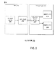
[0046]図2に、GNSS(たとえば、GLONASS)のための信号を受信し、復号するための例示的な受信機200を示す。
[0046] FIG. 2 shows an
[0047]たとえば、GLONASSは、共通コードをもつGNSS信号の一例であり得る。さらに、共通コードをもつGNSS信号は異なる周波数においてブロードキャストされ得、ただし、各信号は異なる衛星からのものである。さらに、各衛星は異なる周波数において動作していることがある(たとえば、各衛星の信号は異なる周波数にある)。 [0047] For example, GLONASS may be an example of a GNSS signal with a common code. Furthermore, GNSS signals with a common code can be broadcast on different frequencies, where each signal is from a different satellite. In addition, each satellite may be operating at a different frequency (eg, each satellite's signal is at a different frequency).
[0048]GLO受信機200は受信機100の一例であり得る。一実施形態では、受信機は、RF210およびベースバンド211など、2モジュール(すなわち集積回路)ソリューションを含むことができる。別の実施形態によれば、RF210およびベースバンド211は、単に、単一のチップ上に実装されたRFおよびベースバンドモジュールであり得る。RF210は、アナログフロントエンド(AFE:analog-front-end)201と、GLONASSのためのデジタルフロントエンドDFE(DFE_GLO202)とを含むことができる。
[0048]
[0049]一実施形態では、AFE201は、図1のLNA105と、ダウンコンバータ106と、増幅段107と、ADC108とを含むことができる。
[0049] In one embodiment, the
[0050]いくつかの事例では、AFE201は、受信されたGLONASS信号のためのアナログデジタル変換器(ADC)信号を出力することができる。DFE_GLO202は、AFE201出力を受信し、RF210の出力のための信号を生成することができる。AFE201は、受信機を備えるフィルタ、増幅器、周波数変換器を含んでいることがある。GLONASS信号は、存在する他の信号(たとえば、GPS、Beidou、Galileo)とは別々に処理され得るか、または信号は一緒に処理され、ベースバンド211中の処理において分離され得る。1つまたは複数の構成では、1つのフィルタは、1つの比較的大きい帯域中でGPSとGLOの両方をパスすることができる。代替的に、各信号(たとえば、GPS、Beidou、GLO)は別々にそれぞれフィルタであり得るが、コストは増加する。
[0050] In some cases, the
[0051]いくつかの事例では、AFE201は、すべての利用可能なGLO衛星を同時に受信され得、衛星を1つの信号として処理し、それらをすべてDFE_GLO202にパスする。たとえば、AFE201およびDFE_GLO202は、後続のブロックが信号を見つけるために、ただある帯域を取り、それを処理することができる。
[0051] In some cases,
[0052]整合フィルタは、拡散信号を逆拡散するために適切なコードが適用されることを示すために使用される用語であり、それは、DFE_GLO202が、処理された信号を生成した後に行われ得る。GLO衛星は異なる中心周波数にある。GLO受信機200のいくつかの実施形態によれば、異なるGLO衛星からの信号は、DFE_GLO202プロセスの後、効果的に分割される。
[0052] Matched filter is a term used to indicate that an appropriate code is applied to despread a spread signal, which may be done after
[0053]1つまたは複数の構成では、DFE_GLO202は、DSP(たとえば、DSP109)とメモリとを含むことができる。DFE_GLO202はまた、本発明のいくつかの実施形態に記載されているようにオフセットとエイリアス除去とを実装することができる。
[0053] In one or more configurations,
[0054]ベースバンド211は、複数の検索エンジン204と複数の追跡エンジン205とを含むことができる。いくつかの事例では、デュアルモードインターフェース203は、RF210の出力を受信し、検索エンジン204のために(たとえば16MHzで)、ならびに追跡エンジン205のために(たとえば8MHzで)信号を生成することができる。他の事例では、ベースバンド211は、複数の入力、たとえば、複数のWAN帯域およびGNSSを受信することができる。したがって、ベースバンド211は他の受信機(たとえば、通信受信機、GNSS受信機)を含むことができる。一実施形態では、ベースバンド211は、これらの機能を実行する標準的なチップを用いて実装され得る。いくつかの実装形態では、図5で説明するオフセットおよびエイリアス除去はベースバンド211によって実装され得る。
[0054] Baseband 211 may include a plurality of
[0055]図3は、信号(たとえば、GNSS信号、GLONASS信号)を受信する低雑音増幅器(LNA)301を含む例示的なAFE201を示すことができる。表面弾性波(SAW:surface acoustic wave)フィルタ302は、LNA301の出力を受信し、バンドパスフィルタ処理を行うことができる。SAWフィルタ302はGLO、GPS、および他の信号を一緒にパスし得る。バッファ303は、SAWフィルタ302の出力を受け、それのバッファされた信号を単一のミキサセット(すなわち単一のI/Qミキサペア)304に与えることができ、セット304のうちの1つのミキサは局部発振器(LO320)からコサイン信号をさらに受信し、セット304のうちの他のミキサはLO320からサイン信号をさらに受信する。これらのミキサ出力は、電流電圧ブロック(I2V)305によって電流モードから電圧モードに変換され、次いで、ポリフェーズフィルタ(PPF:polyphase filter)306に与えられる。PPF306は複素入力(I/Q)を有することができ、イメージ信号(image signal)を削除し得る。いくつかの実施形態では、PPF306はエイリアス除去を実行することができる。電圧利得増幅器(VGA:voltage gain amplifier)307はPPF306の出力を受ける。アナログデジタル変換器(ADC)308(たとえば、2つの8ビットADC)は、VGA307の増幅された出力を受け、次いで、(図2中にコンテキストのために示された)DFE_GLO202に信号を与える。
[0055] FIG. 3 may illustrate an
[0056]代替的に、図3は例示的なRFモジュール101中のモジュールを示すことができる。したがって、1つまたは複数の構成では、図3中のモジュール(たとえば、LO320、PPF306)はRFモジュール101に組み込まれ得る。さらに、1つまたは複数の構成では、図3中のモジュール(たとえば、LO320、PPF306)はDSP109に組み込まれ得る。
[0056] Alternatively, FIG. 3 may show modules in the exemplary RF module 101. Thus, in one or more configurations, the modules in FIG. 3 (eg,
[0057]その上、図3中のAFE201は、局部発振器と他の構成要素との相互作用を詳細に詳述する、図1中のRFモジュール101のより詳細な例であり得る。開示する方法を達成する他の実施形態があり得、この実施形態は限定的でないことに留意されたい。たとえば、AFE201は、ミキサセット304のためにコサイン信号とサイン信号の両方を生成するために使用され得る単一の局部発振器(LO320)含むことができる。さらに、LO320のRF周波数は、GLONASS信号のための所定の中間周波数(IF)を取得するために設定され得る。いくつかの実施形態では、LO320は、図5で説明するオフセットを実行することができる。
[0057] Moreover, the
[0058]LO320は静的にまたは動的に調整され得る。特に、LO周波数の設定は、GLONASSのための(たとえば、ポリフェーズフィルタ(PPF)306のための)フィルタ実装形態に影響を及ぼすことがある。いくつかの事例では、周波数LO320の同調は通常の受信機動作中に動的に実行され得る。
[0058]
[0059]一実施形態では、ポリフェーズフィルタの各々の通過帯域は正の周波数または負の周波数のいずれかとして選択され得る。たとえば、一実施形態では、GLONASSポリフェーズフィルタ極性は負の周波数に切り替えられ得る。そのような切替えは、さもなければGLONASS信号のうちの1つと干渉するであろうスパーを回避するために使用され得る。この通過帯域選択は静的または動的な方法で実行され得る。 [0059] In one embodiment, the passband of each of the polyphase filters may be selected as either a positive frequency or a negative frequency. For example, in one embodiment, the GLONASS polyphase filter polarity may be switched to a negative frequency. Such switching can be used to avoid spurs that would otherwise interfere with one of the GLONASS signals. This passband selection can be performed in a static or dynamic manner.
[0060]現在の実装形態では、受信機は、0Hzにおける帯域を中心とするようにGLO信号をダウンコンバートすることができる。帯域の中心を下回る信号と帯域の中心を上回る信号とは、それらの位相関係に基づいて区別され得る。さらに、信号のI成分とQ成分との間の位相関係は、帯域の中心を上回る信号(たとえば、+周波数、チャネル+1、図4A中のF1)を、帯域の中心を下回る信号(たとえば、−周波数、チャネル−1、図4A中のF2)と区別するのを助けることができる。たとえば、中心周波数を上回る1MHzにおける信号は、信号のI成分とQ成分とに基づいて中心周波数を下回る1MHzにおける信号と区別され得る。 [0060] In current implementations, the receiver can downconvert the GLO signal to center around the band at 0 Hz. Signals below the center of the band and signals above the center of the band can be distinguished based on their phase relationship. Further, the phase relationship between the I and Q components of the signal is such that signals above the center of the band (eg, + frequency, channel + 1, F1 in FIG. 4A) Frequency, channel-1, can help to distinguish from F2) in FIG. 4A. For example, a signal at 1 MHz above the center frequency can be distinguished from a signal at 1 MHz below the center frequency based on the I and Q components of the signal.
[0061]しかしながら、いくつかの事例では、サンプリングされる信号は完全に表されるとは限らず、たとえば、それらは制限されたビット長を有することがあり、したがって、プラス周波数信号とマイナス周波数信号との間の分離は、処理ブロックが信号を区別することが可能であるために必要不可欠でないことがある。たとえば、−1MHz信号における電力は、+1MHz信号を探すときに検出され得る。さらに、図7Dに示されているように、−1MHz信号が強く、+1MHz信号が弱いとき、受信機は間違った信号(たとえば、エイリアス信号)を見つけ得る。所望の信号(たとえば、+1MHz信号)とエイリアス化信号(たとえば、−1MHz信号)とは、異なる周波数における異なる衛星からの異なる信号である。 [0061] However, in some cases, the sampled signals may not be fully represented, for example, they may have a limited bit length, and thus a positive frequency signal and a negative frequency signal. The separation between and may not be essential because the processing block can distinguish the signals. For example, power in a -1 MHz signal can be detected when looking for a +1 MHz signal. Further, as shown in FIG. 7D, when the -1 MHz signal is strong and the +1 MHz signal is weak, the receiver may find the wrong signal (eg, alias signal). The desired signal (eg, +1 MHz signal) and aliased signal (eg, -1 MHz signal) are different signals from different satellites at different frequencies.
[0062]たとえば、検出中に、受信機100は、GLO帯域全体を探し、受信することができる。その後、受信機100(たとえば、RFモジュール101)は、受信された信号を、0Hzを中心とするようにダウンコンバートすることができる。ダウンコンバートされた信号は、0Hzを上回る帯域の前半と、0Hzを下回る帯域の後半とを含むことができる。帯域の前半が、DSP109を使用して後半上に折り返しられるとき、中心を下回る第1のチャネルである−1チャネルは、中心を上回る第1のチャネルである+1チャネルの上にまっすぐに被さることができる。DSP109を使用してオフセットを追加することによって、エイリアス信号は所望の信号とより良く区別され得る。別の実施形態では、オフセットおよびエイリアス除去は、LO320とミキサセット304とPPF306とを使用して実行され得る。
[0062] For example, during detection, the
[0063]前述のように、GLONASS(GLO)衛星は、すべての衛星信号上で同じ符号分割多元接続(CDMA)拡散コードを有する。その結果、正の周波数のためのコードと負の周波数のためのコードとは同じである。したがって、GLOプラスチャネル(たとえば、正の周波数)が負チャネル(たとえば、負の周波数)の上でエイリアス化されるとき、コード分離の方法は余分の分離を与えない。各チャネルが同じコードを有するとすれば、GLOシステムの場合、コード分離は効果的に動作しないことがある。したがって、GLO信号を受信するGLO受信機200は、正しいチャネルおよび信号を見つけるために、オフセットを使用することによってエイリアス信号を効果的に除去するための本明細書で説明する方法を実装することができる。
[0063] As mentioned above, GLONASS (GLO) satellites have the same code division multiple access (CDMA) spreading code on all satellite signals. As a result, the code for the positive frequency and the code for the negative frequency are the same. Thus, when a GLO plus channel (eg, positive frequency) is aliased on a negative channel (eg, negative frequency), the code separation method does not provide extra separation. If each channel has the same code, code separation may not work effectively for GLO systems. Thus, a
[0064]その上、衛星通信では、すべての衛星が頭上にあるので、衛星が同様のレベルにあると間違って仮定され得る。しかしながら、地平線の近くの衛星または物体(たとえば、建築物)によって遮断される衛星は同様のレベルにないことがある。その結果、頭上から強い衛星を受信し、建築物の後ろから弱い信号を受信することは珍しくないことがある。強い信号と弱い信号との間の信号強度の差は30dBよりも大きくなることがある。したがって、図7A〜図7Dに示されているように、信号強度の差が高い(たとえば、20dBよりも大きい)とき、所望の信号上にエイリアス化する負の周波数における強い信号(たとえば、エイリアス信号)を、正の周波数における弱い衛星と識別することは困難であり得る。 [0064] Moreover, in satellite communications, since all satellites are overhead, it can be incorrectly assumed that the satellites are at a similar level. However, satellites that are blocked by satellites or objects (eg, buildings) near the horizon may not be at a similar level. As a result, it is not uncommon to receive strong satellites overhead and weak signals from behind the building. The difference in signal strength between strong and weak signals can be greater than 30 dB. Thus, as shown in FIGS. 7A-7D, when the difference in signal strength is high (eg, greater than 20 dB), a strong signal (eg, an alias signal) at a negative frequency that aliases onto the desired signal. ) Can be difficult to distinguish from weak satellites at positive frequencies.
[0065]間違った信号を検出することは、たとえば、衛星の高度レベルが異なるときに起こることがある。その結果、受信機100が、正しい衛星を検出することを試みるとき、受信機は、正しい衛星の上にエイリアス化された第2の衛星を実際に検出する。これは、CDMAシステムの共通の問題であり、ここではただ1つのコードがあり、受信機は他の衛星を探し続ける。さらに、いくつかのGNSS(たとえば、GLONASS)受信機は、非常に強いエイリアス衛星が低レベルの所望の衛星とともに存在し、弱い衛星(たとえば、所望の信号)の検出がすべてのコード位置における強い衛星の誤検出によってマスキングされる場合を扱うことが困難である。
[0065] Detecting the wrong signal may occur, for example, when the altitude levels of the satellites are different. As a result, when the
[0066]前に説明したように、現在の実装形態は、正の周波数と負の周波数とで信号を表すことができる受信機を有する。信号は、M1とM2とを使用して2つの別個の信号経路を生成することによって別々に保たれ、ただし、信号は、信号処理が正の周波数と負の周波数とを別々に識別することを可能にする特定の位相関係(たとえば、I信号、Q信号)を有することができる。 [0066] As previously described, current implementations have receivers that can represent signals at positive and negative frequencies. The signal is kept separate by using M1 and M2 to create two separate signal paths, except that the signal distinguishes positive and negative frequencies separately. It can have a specific phase relationship (eg, I signal, Q signal) that enables it.
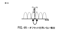
[0067]さらに、GLONASS信号の場合、異なる衛星からの信号は異なる周波数チャネルに分離され得る。したがって、図4A〜図4Bに示されているように、チャネル0が0Hzを中心とするようにシステムがGLONASS信号をダウンコンバートするとき、プラスチャネルがマイナスチャネルと同じ大きさの周波数に被さる強い可能性があり得る。 [0067] Furthermore, for GLONASS signals, signals from different satellites may be separated into different frequency channels. Thus, as shown in FIGS. 4A-4B, when the system downconverts the GLONASS signal so that channel 0 is centered at 0 Hz, the strong possibility that the plus channel will suffer the same magnitude as the minus channel. There can be sex.
[0068]たとえば、LO320がチャネル0の中心に設定されるとき、チャネル1(たとえば、図4A〜図4B中のF1)とチャネル−1(たとえば、図4A〜図4B中のF2)とは同じ周波数の大きさを中心とすることができる。信号は、I信号とQ信号との間の位相関係によって別々に保たれ得る。しかしながら、ハードウェアは完全でないことがあり、したがって、チャネル−1信号を探索するときにチャネル1信号を見る可能性があり、その逆も同様である。
[0068] For example, when
[0069]図4A〜図4Bに、オフセットを用いない現在の実装形態を示す。図4A〜図4Bに示されているように、負の周波数が正の周波数上に折り返されるとき、F1のエイリアスはF2上に被さり得る。したがって、オフセットがない場合、エイリアス除去は十分でないことがあり、受信機100は間違った信号(たとえば、F1)を見つけ得る。
[0069] FIGS. 4A-4B show the current implementation without offset. As shown in FIGS. 4A-4B, when a negative frequency is folded back onto a positive frequency, an alias of F1 can be put on F2. Thus, if there is no offset, antialiasing may not be sufficient and
[0070]いくつかの実施形態に従って、オフセットを使用して信号エイリアス除去を改善する方法について本明細書で説明する。いくつかの事例では、間違った信号を検出することは、DSP109を使用して、ダウンコンバートされた信号をオフセットすることによって最小限に抑えられ得る。ダウンコンバートされた信号をオフセットすることによって、負の周波数(たとえば、F1、エイリアス)が折り返されるとき、負の周波数は2つのチャネル間の中間で被さることができる。たとえば、折り返しプロセスにおいて、プラス周波数(たとえば、F2、所望)上のチャネルはマイナス周波数上のチャネル間の中間であり、それによりエイリアス除去を改善することができる。その結果、受信機が1つの衛星を探索しているとき、受信機はオフセットのために他の衛星を見ないことがある。さらに、DSP109は、オフセット周波数に基づいてエイリアスをフィルタで除去することによってエイリアスを除去することができる。
[0070] A method for improving signal aliasing using offsets is described herein in accordance with some embodiments. In some cases, detecting the wrong signal may be minimized by using the
[0071]たとえば、信号は、しばしば、異なる周波数と異なる振幅との多くの正弦曲線の和としてモデル化される。概して、周波数Fの正弦曲線が周波数Fsを用いてサンプリングされるとき、得られたサンプルは、任意の整数Nについて、周波数(F−NFs)の別の正弦曲線のサンプルと区別不可能である。N≠0に対応する値は周波数Fのイメージまたはエイリアスと呼ばれる。さらに、sin(−wt+θ)=sin(wt−θ+π)、およびcos(−wt+θ)=cos(wt−θ)であるので、負の周波数はそれの絶対値に等しい。したがって、エイリアシングは、それのサンプルから元の波形を再構成するときに起こることがある。 [0071] For example, signals are often modeled as the sum of many sinusoids with different frequencies and different amplitudes. In general, when a sinusoid of frequency F is sampled using frequency F s , the resulting sample is indistinguishable from another sinusoidal sample of frequency (F−NF s ) for any integer N. is there. A value corresponding to N ≠ 0 is called an image or alias of frequency F. Furthermore, since sin (−wt + θ) = sin (wt−θ + π) and cos (−wt + θ) = cos (wt−θ), the negative frequency is equal to its absolute value. Thus, aliasing can occur when reconstructing the original waveform from its samples.
[0072]さらに、振幅対周波数にかかわらず、周波数における単一の正弦曲線についての振幅対周波数のグラフは、0とFsとの間で対称性を呈することがある。この対称性は、折り返しと呼ばれ得る。いくつかの事例では、折り返し周波数はナイキスト周波数と呼ばれることがある。折り返しは、実際には、ほとんどの場合、離散フーリエ変換を使用して実数値サンプルの周波数スペクトルを閲覧するときに観測される。 [0072] Furthermore, regardless of amplitude versus frequency, the amplitude versus frequency graph for a single sinusoid in frequency may exhibit symmetry between 0 and F s . This symmetry can be referred to as folding. In some cases, the folding frequency may be referred to as the Nyquist frequency. Folding is actually observed in most cases when viewing the frequency spectrum of a real-valued sample using a discrete Fourier transform.
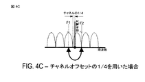
[0073]一実施形態によれば、本方法は、DSP109を使用することによって、図4Cに示されているように、GLONASS信号のダウンコンバートされた中心周波数をチャネルの1/4だけオフセットすることを含むことができ、したがって、プラス周波数におけるチャネルはマイナス周波数のためのチャネルのエッジに被さる。その結果、オフセットはマイナス周波数のためのチャネル中心を正チャネルのエッジに被せることができる。したがって、チャネルをオフセットすることは、エイリアス信号(たとえば、反対の周波数における不要な信号)のはるかに良い除去を行うことができる。たとえば、所望の信号が正の周波数にある場合、エイリアス信号は、折り返しの前に負の周波数にあることになる。
[0073] According to one embodiment, the method uses the
[0074]図4Dに、いくつかの実施形態による、GLONASS信号のダウンコンバートされた中心周波数をチャネルの−1/4だけオフセットすることを含む別の例を示す。 [0074] FIG. 4D illustrates another example including offsetting the downconverted center frequency of a GLONASS signal by -1/4 of the channel, according to some embodiments.
[0075]別の実施形態によれば、エイリアス信号のためのより高い除去を行うために、任意のオフセット(たとえば、チャネルのプラスまたはマイナス1/32、1/16、1/8、1/4、3/4、5/4のオフセット)が使用され得る。
[0075] According to another embodiment, any offset (eg, channel plus or
[0076]図4C〜図4Dに、いくつかの実施形態による、異なるオフセットを用いた実装形態を示す。図4C〜図4Dに示されているように、負の周波数が正の周波数上に折り返されるとき、F1のエイリアスは2つのチャネル間のF2の上に被さることができる。したがって、オフセットを用いると、エイリアス除去は、エイリアス信号を除去するより高い確率を有し、したがって、受信機100は正しい信号をより良く見つけることができる。
[0076] FIGS. 4C-4D illustrate implementations using different offsets according to some embodiments. As shown in FIGS. 4C-4D, when the negative frequency is folded over the positive frequency, an alias of F1 can be placed over F2 between the two channels. Thus, with offsets, alias removal has a higher probability of removing alias signals, and thus the
[0077]チャネルのプラスまたはマイナス1/4、3/4、5/4のオフセットは最大の除去を与えることになるが、他のオフセットは、オフセットを有しないことに勝る次に最適な改善となる。
[0077] Channel plus or
[0078]図4A〜図4D中のグラフを参照すると、x軸は周波数であり、y軸は信号電力である。さらに、GLO信号は、中心にあるピークから511kHzにおいてヌルを有する。衛星周波数は、1つの衛星信号のヌルが隣接する衛星信号のピークにおいて被さるように選ばれ得る。 [0078] Referring to the graphs in FIGS. 4A-4D, the x-axis is frequency and the y-axis is signal power. Furthermore, the GLO signal has a null at 511 kHz from the central peak. The satellite frequency may be chosen such that one satellite signal's null is covered at the peak of the adjacent satellite signal.
[0079]図4C〜図4Dによって示された方法は、外部アンテナ104を使用して高周波信号を受信するために受信機100を使用して実装され得る。受信された信号は、より低い周波数においてダウンコンバートされた信号を処理するために、ダウンコンバータ106を使用してより低い周波数にダウンコンバートされ得る。いくつかの事例では、ダウンコンバートするために使用されるより低い周波数は0ヘルツ(Hz)を中心とすることができる。
[0079] The method illustrated by FIGS. 4C-4D may be implemented using
[0080]たとえば、ダウンコンバージョンは、受信された信号をLO320と混合することによって達成され得、ただし、混合プロセスの出力は、受信された信号周波数−LO周波数に等しい周波数においてダウンコンバートされた信号である。
[0080] For example, down-conversion can be achieved by mixing the received signal with
[0081]さらに、LO320は、ダウンコンバートされた信号が0を中心とするために、受信された信号の中心と同じ周波数に設定される。したがって、LO320がその信号を中心とするとき、LO周波数を上回る周波数は、LO周波数を下回る周波数上に折り返される。
[0081] Further,
[0082]本明細書で説明する「正の周波数」という用語は、LO周波数を上回る入力信号周波数のダウンコンバージョンから生じるダウンコンバートされた信号の信号成分を指すことができる。さらに、本明細書で説明する「負の周波数」という用語は、LO周波数を下回る入力信号周波数のダウンコンバージョンから生じるダウンコンバートされた信号の信号成分を指すことができる。 [0082] The term "positive frequency" described herein can refer to the signal component of a downconverted signal resulting from downconversion of the input signal frequency above the LO frequency. Further, the term “negative frequency” described herein can refer to the signal component of the downconverted signal resulting from downconversion of the input signal frequency below the LO frequency.
[0083]さらに、ダウンコンバートされた信号が0ヘルツ(Hz)周波数を中心とするとき、受信機100は、異なる衛星に割り当てられた、正の周波数でのGLONASS(GLO)チャネルと負の周波数でのGLONASS(GLO)チャネルとを識別するために、位相とコードとを使用することができる。しかしながら、この方法を使用して、システムは、特定のチャネルを探索するときに異なるエイリアスチャネルを見つけ得る。
[0083] Further, when the down-converted signal is centered on a zero hertz (Hz) frequency, the
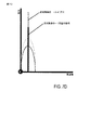
[0084]図5で説明するプロセスに示されているように、受信機100は、オフセットを使用することによってエイリアス除去を改善することができる。たとえば、正の周波数におけるチャネルと負の周波数におけるチャネルとを識別するのを助けるために、RFモジュール101はGNSS(たとえば、GLONASS)信号をダウンコンバートされた信号に処理することができる。前述のように、GLONASSは、共通コードをもつGNSS信号の一例であり得る。さらに、共通コードをもつGNSS信号は異なる周波数においてブロードキャストされ得、ただし、各信号は異なる衛星からのものである。さらに、各衛星は異なる周波数において動作していることがある(たとえば、各衛星の信号は異なる周波数にある)。
[0084] As shown in the process described in FIG. 5, the
[0085]1つまたは複数の構成では、DSP109は、折り返された正の周波数チャネルの中心が負の周波数チャネルの中心間の中間で被さることができ、その逆も同様であるオフセットを含むように、ダウンコンバートされた信号を処理することができる。正の周波数の中心を負の周波数の中心間の中間で被せることによって、(たとえば、オフセット周波数に基づく)余分の量の分離が行われる。したがって、受信機100(たとえば、DSP109)は、余分の量の分離を用いて正の周波数におけるチャネルと負の周波数におけるチャネルとをより良く識別することができる。
[0085] In one or more configurations, the
[0086]510において、受信機100(たとえば、RFモジュール101、モバイルデバイス)は複数のGNSS信号を受信し、ここにおいて、複数のGNSS信号は所望のGNSS信号を含む。1つまたは複数の構成では、外部アンテナ104を使用するRFモジュール101はGNSS(たとえば、GLONASS)信号を受信することができる。いくつかの実施形態では、510における受信機100は受信機システム1050によって実装される。そのような実施形態では、510の少なくとも一部は、たとえば、変調器1080と組み合わせて、たとえば、トランシーバ1052によって実行されるか、ならびに/あるいはたとえば、データソース1036および/またはメモリ1072からの情報および/または命令と組み合わせて、プロセッサ1038、1060、および1070のうちの1つまたは複数によって実行され得る。
[0086] At 510, a receiver 100 (eg, RF module 101, mobile device) receives a plurality of GNSS signals, where the plurality of GNSS signals include a desired GNSS signal. In one or more configurations, the RF module 101 using the
[0087]520において、受信機100(たとえば、RFモジュール101)は、受信された複数のGNSS信号をダウンコンバートされた信号に処理し、ここにおいて、ダウンコンバートされた信号が所望のGNSS信号よりも低い周波数を有し、ここにおいて、ダウンコンバートされた信号が、非0周波数に関連する第1のチャネルを含む。1つまたは複数の構成では、前に説明したように、RFモジュール101またはAFE201は、520において、受信されたGNSS信号(たとえば、GLONASS)をダウンコンバートされた信号に処理する。ダウンコンバートされた信号は、所望のGNSS信号に関連する中心周波数よりも低い周波数を有することができる。いくつかの実施形態では、520における受信機100は受信機システム1050によって実装される。そのような実施形態では、520の少なくとも一部は、たとえば、変調器1080と組み合わせて、たとえば、トランシーバ1052によって実行されるか、ならびに/あるいはたとえば、データソース1036および/またはメモリ1072からの情報および/または命令と組み合わせて、プロセッサ1038、1060、および1070のうちの1つまたは複数によって実行され得る。
[0087] At 520, the receiver 100 (eg, RF module 101) processes the received plurality of GNSS signals into a downconverted signal, where the downconverted signal is more than the desired GNSS signal. Having a low frequency, wherein the downconverted signal includes a first channel associated with a non-zero frequency. In one or more configurations, as previously described, RF module 101 or
[0088]さらに、1つまたは複数の構成では、ダウンコンバートされた信号は、正の周波数に関連する第1のチャネルと負チャネルに関連する第2のチャネルとを有する。一実施形態によれば、受信されたGNSS信号は、ダウンコンバータ106を使用してダウンコンバートされ得る。いくつかの事例では、RFモジュール101は、0Hzにおける帯域を中心とするようにGLO信号をダウンコンバートすることができる。
[0088] Further, in one or more configurations, the downconverted signal has a first channel associated with a positive frequency and a second channel associated with a negative channel. According to one embodiment, the received GNSS signal may be down converted using the
[0089]530において、受信機100(たとえば、DSP109)は、オフセットされたダウンコンバートされた信号を作成するために第1のチャネルの分数に対応するオフセット周波数だけ第1のチャネルをオフセットするように、ダウンコンバートされた信号を処理する。1つまたは複数の構成では、DSP109は、正の周波数に関連する第1のチャネルを、530において受信された第1のチャネルの分数に対応するオフセット周波数だけオフセットするために、ダウンコンバートされた信号を処理することができる。図4C〜図4Dは、オフセットを有するためにダウンコンバートされた信号を処理する例を示している。オフセットを使用して、折り返された正の周波数チャネルの中心は、負の周波数チャネルの中心間の中間で被さり、したがって、エイリアス除去を改善することができる。いくつかの実施形態では、530における受信機100は受信機システム1050によって実装される。そのような実施形態では、530の少なくとも一部は、たとえば、変調器1080と組み合わせて、たとえば、トランシーバ1052によって実行されるか、ならびに/あるいはたとえば、データソース1036および/またはメモリ1072からの情報および/または命令と組み合わせて、プロセッサ1038、1060、および1070のうちの1つまたは複数によって実行され得る。
[0089] At 530, the receiver 100 (eg, DSP 109) offsets the first channel by an offset frequency corresponding to a fraction of the first channel to create an offset downconverted signal. Process the downconverted signal. In one or more configurations, the
[0090]540において、受信機100(たとえば、DSP109)は、オフセット周波数に基づいて、オフセットされたダウンコンバートされた信号から所望のGNSS信号を決定する。たとえば、DSP109は、オフセットされたダウンコンバートされた信号を逆拡散することができる。ダウンコンバートされた信号は、エイリアス化信号(たとえば、負の周波数に関連する第2のチャネル)を含むことができる。8Dに示されているように、DSP109は、オフセット周波数に基づく周波数範囲に対してフィルタ処理することによって、逆拡散後に、エイリアス化信号を除去することができる。したがって、エイリアス化信号はフィルタで除去され得る。1つまたは複数の構成では、DSP109は、オフセットされたダウンコンバートされた信号を逆拡散するために使用され、オフセット周波数に基づいてエイリアス化信号を除去するために使用され得る。図8A〜図8Dでは、オフセット周波数に基づいてエイリアス化信号を除去する方法についてさらに説明する。いくつかの実施形態では、540における受信機100は受信機システム1050によって実装される。そのような実施形態では、540の少なくとも一部は、たとえば、変調器1080と組み合わせて、たとえば、トランシーバ1052によって実行されるか、ならびに/あるいはたとえば、データソース1036および/またはメモリ1072からの情報および/または命令と組み合わせて、プロセッサ1038、1060、および1070のうちの1つまたは複数によって実行され得る。
[0090] At 540, receiver 100 (eg, DSP 109) determines a desired GNSS signal from the offset down-converted signal based on the offset frequency. For example, the
[0091]場合によっては、540において決定することは、オフセットされたダウンコンバートされた信号を逆拡散すること、ここで、オフセットされたダウンコンバートされた信号が、第1のチャネルに関連するエイリアス化信号を含む、をさらに備え得る。さらに、540において決定することは、オフセット周波数に基づいてエイリアス信号をフィルタで除去することによってエイリアス化信号を除去することをさらに備え得る。前述のように、DSP109はエイリアス信号の逆拡散と除去とを実装することができる。
[0091] In some cases, determining at 540 despreads the offset downconverted signal, where the offset downconverted signal is aliased with respect to the first channel. Including a signal. Further, determining at 540 may further comprise removing the aliased signal by filtering the alias signal based on the offset frequency. As described above, the
[0092]1つまたは複数の構成では、第1のチャネルは正の周波数である。さらに、ダウンコンバートされた信号は0ヘルツまたはその近くを中心とすることができる。その上、ダウンコンバートされた信号は、負の周波数に関連する第2のチャネルを含む。530におけるオフセットは、第1のチャネルの中心が第2のチャネルの中心からオフセットされることとなる。この例では、第1のチャネルに関連するエイリアス化信号の中心と、第2のチャネルに関連する所望のGNSS信号の中心とは、オフセット周波数に基づいてオフセットされる。 [0092] In one or more configurations, the first channel is a positive frequency. Further, the downconverted signal can be centered at or near zero hertz. In addition, the downconverted signal includes a second channel associated with the negative frequency. The offset at 530 is that the center of the first channel is offset from the center of the second channel. In this example, the center of the aliased signal associated with the first channel and the center of the desired GNSS signal associated with the second channel are offset based on the offset frequency.
[0093]代替的に、1つまたは複数の構成では、第1のチャネルは負の周波数である。ダウンコンバートされた信号は0ヘルツまたはその近くを中心とし、ダウンコンバートされた信号。さらに、ダウンコンバートされた信号は、正の周波数に関連する第2のチャネルをさらに含む。530におけるオフセットは、第1のチャネルの中心が第2のチャネルの中心からオフセットされることとなる。この例では、第1のチャネルに関連するエイリアス化信号の中心と、第2のチャネルに関連する所望のGNSS信号の中心とは、オフセット周波数に基づいてオフセットされる。 [0093] Alternatively, in one or more configurations, the first channel is a negative frequency. Down-converted signal is a signal down-converted around 0 Hz or near. Furthermore, the downconverted signal further includes a second channel associated with the positive frequency. The offset at 530 is that the center of the first channel is offset from the center of the second channel. In this example, the center of the aliased signal associated with the first channel and the center of the desired GNSS signal associated with the second channel are offset based on the offset frequency.
[0094]さらに、ダウンコンバートされた信号への受信されたGNSS信号の処理は、部分的に、周波数が所望の信号に等しい、(たとえば、RFモジュール101、LO320中に含まれる)局部発振器によって行われ得る。さらに、オフセット周波数だけ第1のチャネルをオフセットするためのダウンコンバートされた信号の処理は、部分的にデジタル信号プロセッによって行われ得る。オフセット周波数は第1のチャネルの1/4、3/4、1/8、1/16、1/32であり得る。 [0094] Further, processing of the received GNSS signal into a downconverted signal is performed in part by a local oscillator (eg, included in RF module 101, LO 320) whose frequency is equal to the desired signal. Can be broken. Further, processing of the downconverted signal to offset the first channel by an offset frequency can be performed in part by a digital signal processor. The offset frequency may be 1/4, 3/4, 1/8, 1/16, 1/32 of the first channel.
[0095]その上、オフセット周波数=(1/4+N*1/2)*Channel_Spacingであり、ただし、Nは整数であり、Channel_Spacingは、第1のチャネルに関連するチャネル間隔である。 [0095] Moreover, offset frequency = (1/4 + N * 1/2) * Channel_Spacing, where N is an integer, and Channel_Spacing is the channel spacing associated with the first channel.
[0096]1つまたは複数の構成では、RFモジュール101は、DSP109によって折り返されるときに第1のチャネルの中心が第2のチャネルの中心からオフセットされるように、第1のチャネルと第2のチャネルとをオフセットすることができる。さらに、DSP109は、図8Dに示されているようにオフセット周波数に基づいてエイリアスを除去することができる。
[0096] In one or more configurations, the RF module 101 includes a first channel and a second channel such that the center of the first channel is offset from the center of the second channel when folded by the
[0097]1つまたは複数の構成では、正の周波数の中心は、ダウンコンバートされた信号をミキサセット304(たとえば、M1、M2)に入力することによって、負の周波数の中心間の中間で被さることができる。ミキサセット304のためのLO320は同じ周波数にあるが、90度の位相関係があり得る。したがって、ミキサセット304から出力される処理された信号は、同相および直交位相を表すことができるIおよびQと標示され得る。さらに、ミキサセット304から出力される処理された信号は、IまたはQのいずれかと標示され得、それは任意であり得る。たとえば、ミキサM1に適用されるLO320は0度にあり得、ミキサM2に適用されるLO320は90度だけシフトされ得る。さらに、LO320を上回るダウンコンバートされた信号はミキサM1およびM2の出力に混合され得る。その結果、LO320を上回る周波数をもつダウンコンバートされた信号から来る、M1から出力されるすべての周波数成分は、M2からの同じ成分よりも90度だけ進むことができる。代替的に、LOを下回る周波数をもつダウンコンバートされた信号からの、M1から出力されるすべての信号成分は、M2から出力される周波数成分よりも90度だけ遅れることができる。したがって、受信機100は、正の周波数を負の周波数と識別するために進みおよび遅れ(lead and lag)関係を使用することができる。
[0097] In one or more configurations, the center of the positive frequency is covered in the middle between the centers of the negative frequency by inputting the downconverted signal into mixer set 304 (eg, M1, M2). be able to. The
[0098]さらに、現実のシステムは、分離がどのくらいうまく働くかに対する制限を有することができる。較正がないシステムは、正の周波数と負の周波数との間に約20dBの分離を有することができる。たとえば、正の周波数と負の周波数とがそれぞれ等しいレベルで正弦波を有するとき、正の周波数を探すシステムはまた、正の周波数よりも20dB低いところにある負の周波数を見ることができる。さらに、較正を用いるシステムは、30dB以上の分離を有することができる。 [0098] Furthermore, real-world systems can have limitations on how well separation works. A system without calibration can have a separation of about 20 dB between positive and negative frequencies. For example, when the positive and negative frequencies each have a sine wave at equal levels, a system looking for a positive frequency can also see a negative frequency that is 20 dB below the positive frequency. Further, a system using calibration can have a separation of 30 dB or more.
[0099]図6に示されているように、GLO信号はまた、CDMAコード拡散を使用する。GPSおよび他のCDMAシステムでは、様々な信号は異なる拡散コードを有するが、GLOでは、コードはすべての衛星に対して同じである。その結果、GLO信号は、チャネルを識別する際のコード分離の利点を有しないことがある。したがって、システムによるいかなる逆拡散プロセスも2つ以上のGLO衛星を見つけることができる。異なるGLO衛星からの信号は、各衛星について異なるコード位置にあり得るが、コード分離のためにピークレベルの緩和がない。 [0099] As shown in FIG. 6, the GLO signal also uses CDMA code spreading. In GPS and other CDMA systems, the various signals have different spreading codes, but in GLO, the codes are the same for all satellites. As a result, GLO signals may not have the advantage of code separation in identifying channels. Thus, any despreading process by the system can find more than one GLO satellite. Signals from different GLO satellites may be at different code locations for each satellite, but there is no peak level relaxation due to code separation.
[0100]以下の例では、チャネル+1は所望の信号であり、チャネル−1はイメージである。 [0100] In the following example, channel +1 is the desired signal and channel -1 is the image.
[0101]図7A〜図8Dでは、y軸は信号電力を表すことができ、x軸は周波数を表すことができる。さらに、GLO信号は、中心にあるピークから511kHzにおいてヌルを有する。衛星周波数は、1つの衛星信号のヌルが隣接する衛星信号のピークにおいて被さるように選ばれ得る。さらに、いくつかの事例では、最も暗い曲線は所望の衛星信号であると仮定され、他のハイライトされた信号は不要なエイリアスであり、信号の残りは、干渉を実際に生じていない他の衛星を示すためにそこにある。 [0101] In FIGS. 7A-8D, the y-axis can represent signal power and the x-axis can represent frequency. Furthermore, the GLO signal has a null at 511 kHz from the central peak. The satellite frequency may be chosen such that one satellite signal's null is covered at the peak of the adjacent satellite signal. In addition, in some cases, the darkest curve is assumed to be the desired satellite signal, the other highlighted signals are unwanted aliases, and the rest of the signal is the other that is not actually causing interference. Is there to show the satellite.
[0102]図7Aに、受信機100がチャネル0を0Hzの中心周波数にダウンコンバートするときの一例を示す。さらに、チャネル1およびチャネル−1はミキサ(たとえば、M1、M2)からの同じ周波数にあるが、チャネル−1は負の周波数にあり、チャネル+1は正の周波数にある。さらに、説明した欠陥をもつIおよびQ信号は、これらの信号を表すために使用される。
[0102] FIG. 7A shows an example when
[0103]さらに、図7Bに、チャネル−1の大きさがチャネル+1の大きさよりも40dB高いシナリオを示す。図7Cに示されているように、図7B中の例からの負の周波数(たとえば、チャネル−1)が正の周波数(たとえば、チャネル+1)上に折り返しられるとき、チャネル+1からの信号はチャネル−1からのイメージよりも低い。
[0103] Further, FIG. 7B shows a scenario in which the size of channel-1 is 40 dB higher than the size of
[0104]図7Dに示されているように、7Cからのダウンコンバートされた信号が逆拡散されるとき、エイリアス信号(たとえば、チャネル−1)は所望の信号(たとえば、チャネル+1)よりも高い電力を有することができる。したがって、このシステムにおけるイメージ除去は−1信号の高レベルのために、−1チャネル信号を正しく除去するには不十分であり得る。 [0104] As shown in FIG. 7D, when the downconverted signal from 7C is despread, the alias signal (eg, channel -1) is higher than the desired signal (eg, channel +1). Can have power. Therefore, image removal in this system may be insufficient to correctly remove the -1 channel signal due to the high level of the -1 signal.
[0105]本発明のいくつかの実施形態によれば、受信機100は、エイリアスまたはイメージ信号を正しく除去するために、エイリアスチャネルが所望のチャネル上で直接被さるのを停止することができる。ある実施形態では、システムは、オフセットを使用することによって、エイリアスチャネルが所望のチャネル上で直接被さるのを停止することができる。たとえば、GLONASSの場合、オフセットは、ミキサ(たとえば、M1、M2)からの出力をオフセットするためにLOを使用することによって、チャネルの中心が0Hzから127.75kHzであるところにあり得る。いくつかの事例では、オフセットは他の周波数にあり得る。代替的に、DSP109は、オフセットを実装するために使用され得る。オフセットは、エイリアス信号の中心周波数を、所望の信号の中心とは異なる周波数に配置し、エイリアス信号の存在下で所望の信号の検出を改善する任意の量であり得る。
[0105] According to some embodiments of the present invention, the
[0106]1つまたは複数の構成では、ダウンコンバートされた信号は、第1のチャネルの分数に対応するオフセット周波数だけオフセットされ得る。分数は、限定はしないが、1/32、1/16、1/8、1/4、3/4または5/4を含むことができる。分数は、エイリアス除去を改善する任意の値であり得る。エイリアス除去は、イメージ信号のピークから離れて所望の信号のピークをシフトすることによって改善され得る。 [0106] In one or more configurations, the downconverted signal may be offset by an offset frequency corresponding to a fraction of the first channel. Fractions can include, but are not limited to, 1/32, 1/16, 1/8, 1/4, 3/4, or 5/4. The fraction can be any value that improves anti-aliasing. Anti-aliasing can be improved by shifting the peak of the desired signal away from the peak of the image signal.
[0107]図8Aに、一実施形態による、オフセットを使用することによって、エイリアスチャネルが所望のチャネル上で直接被さるのを止める方法を示す。図8Aに示されたチャネル間隔(たとえば、Channel_Spacing)は、2つの異なるチャネル間の周波数差(たとえば、チャネルの周波数幅)であり得る。受信された信号がダウンコンバートされるとき、LOは、図8Aに示されているように、チャネル0の中心からチャネルの1/8に配置され得る。代替的に、DSP109は、図8Aに示されたオフセットを実装するために使用され得る。
[0107] FIG. 8A illustrates a method for stopping an alias channel from directly covering a desired channel by using an offset, according to one embodiment. The channel spacing (eg, Channel_Spacing) shown in FIG. 8A may be a frequency difference between two different channels (eg, channel frequency width). When the received signal is downconverted, the LO can be placed from the center of channel 0 to 1/8 of the channel, as shown in FIG. 8A. Alternatively, the
[0108]処理において、システムはチャネル+1を探していることがあるが、図8Bに示されているように、チャネル−1はチャネル+1よりも40dB高い。 [0108] In processing, the system may be looking for channel +1, but channel -1 is 40 dB higher than channel +1, as shown in FIG. 8B.
[0109]チャネル−1のエイリアスは、図8Cに示されているように、チャネル+1の中心からチャネル1/4に被さることができる。GLONASSの場合、処理された信号が逆拡散されるときのオフセットの結果として、チャネル−1信号は、図8Dに示されているようにチャネル+1のための信号からほぼ128kHz離れ得る。さらに、前述のように、オフセットのために、チャネル−1からの任意の相互相関積は、著しく低減され得る。したがって、逆拡散した後に、DSP109は、特定の周波数(たとえば、オフセット周波数)に関連する周波数範囲に対してフィルタ処理することができ、エイリアス信号は除去され得(たとえば、フィルタで除去され得)、所望の信号は正しく決定され得る。その結果、所望の信号(たとえば、チャネル+1に関連するGLONASS信号)は、オフセット周波数に基づいて決定され得る。代替的に、ベースバンドモジュール102、DFE_GLO202、および/またはベースバンド211はエイリアス除去のために使用され得る。
[0109] The alias for channel-1 may span
[0110]いくつかの事例では、オフセットを使用することは、エイリアス除去を改善することができる。たとえば、図5に示されたプロセスは、GLONASS受信機におけるエイリアス除去を10dB超だけ改善することができる。 [0110] In some cases, using an offset can improve alias removal. For example, the process shown in FIG. 5 can improve alias removal in a GLONASS receiver by more than 10 dB.
[0111]次に、本開示の様々な態様がその中で実装され得るコンピューティングシステムの例について図9に関して説明する。コンピューティングシステムは、および本明細書の他の場所で参照したように、受信機100と、DSP109と、GLO受信機200と、AFE201と、DFE GLO202とを例示し得る。1つまたは複数の態様によれば、図9に示したコンピュータシステムは、本明細書で説明した特徴、方法、および/または方法ステップのうちのいずれかおよび/またはすべてを実装、実施、および/または実行し得る、コンピューティングデバイスの一部として組み込まれ得る。たとえば、コンピュータシステム900はハンドヘルドデバイスの構成要素のうちのいくつかを表し得る。ハンドヘルドデバイスは、カメラおよび/またはディスプレイユニットなど、入力知覚ユニットをもつ何らかのコンピューティングデバイスであり得る。ハンドヘルドデバイスの例としては、限定はしないが、ビデオゲームコンソール、タブレット、スマートフォン、およびモバイルデバイスがある。一実施形態では、システム900は、図5で説明した方法500を実装するように構成される。図9は、本明細書で説明した、様々な他の実施形態によって与えられる方法を実行することができ、および/またはホストコンピュータシステム、リモートキオスク/端末、ポイントオブセールデバイス、モバイルデバイス、セットトップボックス、および/またはコンピュータシステムとして機能することができるコンピュータシステム900の一実施形態の概略図を与える。図9は、そのうちのいずれかおよび/またはすべてが適宜に利用され得る、様々な構成要素の一般化された図を提供するものにすぎない。図9は、したがって、個々のシステム要素が、比較的分離された方法または比較的より統合された方法で、どのように実装され得るかを概括的に示している。
[0111] An example computing system in which various aspects of the present disclosure may be implemented will now be described with respect to FIG. The computing system may illustrate the
[0112]バス905を介して電気的に結合され得る(または、適宜に、他の方法で通信していることがある)ハードウェア要素を備えるコンピュータシステム900が示されている。一実施形態では、バス905はデータバス103であり得る。ハードウェア要素は、限定はしないが、(デジタル信号処理チップ、グラフィックスアクセラレーションプロセッサなど)1つまたは複数の汎用プロセッサおよび/または1つまたは複数の専用プロセッサを含む1つまたは複数のプロセッサ910(たとえば、DSP109、メインプロセッサ111)と、限定はしないが、カメラ、マウス、キーボードなどを含むことができる1つまたは複数の入力デバイス915と、限定はしないが、ディスプレイユニット、プリンタなどを含むことができる1つまたは複数の出力デバイス920とを含み得る。
[0112] A
[0113]コンピュータシステム900は、1つまたは複数の非一時的ストレージデバイス925をさらに含み得(および/または、それらと通信していることがあり)、非一時的ストレージデバイス925は、限定はしないが、ローカルストレージおよび/またはネットワークアクセス可能ストレージを備えることができ、ならびに/あるいは、限定はしないが、メモリ110と、ディスクドライブと、ドライブアレイと、光ストレージデバイスと、プログラム可能、フラッシュアップデート可能などであり得る、ランダムアクセスメモリ(「RAM」)および/または読取り専用メモリ(「ROM」)などのソリッドステートストレージデバイスとを含むことができる。そのような記憶デバイスは、限定はしないが、様々なファイルシステム、データベース構造などを含む、何らかの適切なデータストレージを実装するように構成され得る。
[0113] The
[0114]コンピュータシステム900はまた、限定はしないが、モデム、ネットワークカード(ワイヤレスまたはワイヤード)、赤外線通信デバイス、(Bluetooth(登録商標)デバイス、802.11デバイス、WiFi(登録商標)デバイス、WiMax(登録商標)デバイス、セルラー通信設備などの)ワイヤレス通信デバイスおよび/またはチップセットなどを含むことができる、通信サブシステム1330を含み得る。本発明の一実施形態によれば、受信機100、GLO受信機200は、通信サブシステム930の例であり得る。別の実施形態によれば、GLO受信機200は別個の通信サブシステムであり得る。1つまたは複数の構成では、コンピューティングデバイス900は、各々がそれのそれぞれの通信サブシステム930をもつ複数の通信モードを有することができるので、コンピューティングデバイス900は通信サブシステム930の複数の事例を有することができる。通信サブシステム930は、データが、(一例を挙げると、以下で説明するネットワークなどの)ネットワーク、他のコンピュータシステム、および/または本明細書で説明した任意の他のデバイスと交換されることを可能にし得る。多くの実施形態では、コンピュータシステム900は、上記で説明したように、RAMデバイスまたはROMデバイスを含むことができる非一時的ワーキングメモリ935をさらに備え得る。本発明の一実施形態によれば、メモリ110は、非一時的ワーキングメモリ935の例であり得る。
[0114] The
[0115]コンピュータシステム900はまた、オペレーティングシステム940、デバイスドライバ、実行可能ライブラリ、および/または1つまたは複数のアプリケーションプログラム945などの他のコードを含む、ワーキングメモリ935内に現在位置するものとして示されている、ソフトウェア要素を備えることができ、1つまたは複数のアプリケーションプログラム945は、様々な実施形態によって提供されるコンピュータプログラムを備え得、ならびに/あるいは、本明細書で説明した、他の実施形態によって提供される方法を実装するようにおよび/またはシステムを構成するように設計され得る。単に例として、上記で説明した(1つまたは複数の)方法に関して説明した1つまたは複数のプロシージャは、たとえば、図5に関して説明したように、コンピュータ(および/またはコンピュータ内のプロセッサ)によって実行可能なコードおよび/または命令として実装され得、一態様では、次いで、そのようなコードおよび/または命令は、説明した方法に従って1つまたは複数の動作を実行するように汎用コンピュータ(または他のデバイス)を構成し、および/または適応させるために使用され得る。たとえば、デジタル化された信号はワーキングメモリ935に記憶され得る。
[0115]
[0116]これらの命令および/またはコードのセットは、上記で説明した(1つまたは複数の)ストレージデバイス925などのコンピュータ可読記憶媒体上に記憶され得る。場合によっては、記憶媒体は、コンピュータシステム900などのコンピュータシステム内に組み込まれ得る。他の実施形態では、記憶媒体は、コンピュータシステムとは別個(たとえば、コンパクトディスクなどの取外し可能媒体)であり、ならびに/あるいは、記憶媒体が、その上に記憶された命令/コードで汎用コンピュータをプログラムし、構成し、および/または適応させるために使用され得るようなインスタレーションパッケージで提供され得る。これらの命令は、コンピュータシステム900によって実行可能である実行可能コードの形態をとり得、ならびに/あるいは、(たとえば、様々な一般に利用可能なコンパイラ、インストールプログラム、圧縮/解凍ユーティリティなどのいずれかを使用して)コンピュータシステム700上でコンパイルおよび/またはインストールしたときに実行可能コードの形態をとる、ソースコードおよび/またはインストール可能コードの形態をとり得る。
[0116] These instructions and / or sets of code may be stored on a computer-readable storage medium, such as the storage device (s) 925 described above. In some cases, the storage medium may be incorporated within a computer system such as
[0117]特定の要件に従って、実質的な変形が行われ得る。たとえば、カスタマイズされたハードウェアも使用され得、ならびに/あるいは、特定の要素が、ハードウェア、(アプレットなどのポータブルソフトウェアを含む)ソフトウェア、または両方で実装され得る。さらに、ネットワーク入力/出力デバイスなど、他のコンピューティングデバイスへの接続が採用され得る。 [0117] Substantial variations can be made according to specific requirements. For example, customized hardware may be used and / or certain elements may be implemented in hardware, software (including portable software such as applets), or both. In addition, connections to other computing devices such as network input / output devices may be employed.
[0118]いくつかの実施形態は、本開示による方法を実行するための(コンピュータシステム900などの)コンピュータシステムを採用し得る。たとえば、説明した方法のプロシージャの一部または全部は、ワーキングメモリ935中に含まれている(オペレーティングシステム940および/またはアプリケーションプログラム945などの他のコード中に組み込まれ得る)1つまたは複数の命令の1つまたは複数のシーケンスをプロセッサ910が実行するのに応答して、コンピュータシステム900によって実行され得る。そのような命令は、(1つまたは複数の)ストレージデバイス925のうちの1つまたは複数など、別のコンピュータ可読媒体から作業メモリ935に読み込まれ得る。単に例として、ワーキングメモリ935中に含まれている命令のシーケンスの実行は、本明細書で説明した方法の1つまたは複数のプロシージャ、たとえば、図5に関して説明した方法の要素のうちの1つまたは複数を(1つまたは複数の)プロセッサ910に実行させ得る。
[0118] Some embodiments may employ a computer system (such as computer system 900) for performing the method according to the present disclosure. For example, some or all of the procedures of the described method are included in working
[0119]本明細書で使用する「機械可読媒体」および「コンピュータ可読媒体」という用語は、機械を特定の様式で動作させるデータを与えることに関与する任意の媒体を指す。コンピュータシステム900を使用して実装される一実施形態では、様々なコンピュータ可読媒体は、実行のために(1つまたは複数の)プロセッサ910に命令/コードを与えることに関与し得、ならびに/あるいはそのような命令/コードを(たとえば、信号として)記憶および/または搬送するために使用され得る。多くの実装形態では、コンピュータ可読媒体は物理および/または有形記憶媒体である。そのような媒体は、限定はしないが、不揮発性媒体、揮発性媒体、および伝送媒体を含む多くの形態をとり得る。不揮発性媒体は、たとえば、(1つまたは複数の)ストレージデバイス925などの光ディスクおよび/または磁気ディスクを含む。揮発性媒体は、限定はしないが、ワーキングメモリ935などのダイナミックメモリを含む。伝送媒体は、限定はしないが、同軸ケーブル、バス905を備えるワイヤを含む銅線および光ファイバー、ならびに通信サブシステム930の様々な構成要素(および/または通信サブシステム930がそれによって他のデバイスとの通信を行う媒体)を含む。したがって、伝送媒体はまた、(限定はしないが、電波通信および赤外線データ通信中に生成されるものなど、電波、音響波および/または光波を含む)波の形態をとることができる。いくつかの実施形態によれば、受信機100、GLO受信機200は、互いに通信するために通信サブシステム930を利用することができる。
[0119] As used herein, the terms "machine-readable medium" and "computer-readable medium" refer to any medium that participates in providing data that causes a machine to operation in a specific fashion. In one embodiment implemented using
[0120]図10は、システム1000中の送信機システム1010と受信機システム1050との一実施形態のブロック図である。いくつかの実施形態によれば、送信機システム1010は受信機100の一例であり得る。さらに、受信機システム1050は受信機100またはGLO受信機200の一例であり得る。
FIG. 10 is a block diagram of one embodiment of a transmitter system 1010 and a receiver system 1050 in
[0121]送信機システム1010において、いくつかのデータストリームのトラフィックデータがデータソース1012から送信(TX)データプロセッサ1014に与えられる。いくつかの実施形態では、各データストリームは、それぞれの送信アンテナを介して送信される。TXデータプロセッサ1014は、コード化データを与えるために、各データストリームのトラフィックデータを、そのデータストリーム用に選択された特定のコーディング方式に基づいてフォーマットし、コーディングし、インターリーブする。 [0121] At transmitter system 1010, traffic data for several data streams is provided from a data source 1012 to a transmit (TX) data processor 1014. In some embodiments, each data stream is transmitted via a respective transmit antenna. TX data processor 1014 formats, codes, and interleaves the traffic data for each data stream based on the particular coding scheme selected for that data stream to provide coded data.
[0122]各データストリームのコード化データは、OFDM技法を使用してパイロットデータと多重化され得る。パイロットデータは、典型的には、知られている方法で処理されると知られているデータパターンであり、チャネル応答を推定するために受信機システムにおいて使用され得る。各データストリームの多重化されたパイロットデータおよびコード化データは、次いで、変調シンボルを与えるために、そのデータストリーム用に選択された特定の変調方式(たとえば、BPSK、QSPK、M−PSK、またはM−QAM)に基づいて変調(すなわち、シンボルマッピング)される。データストリームごとのデータレート、コーディング、および変調は、プロセッサ1030によって実行される命令によって決定される場合がある。命令はメモリ1032に記憶され得る。
[0122] The coded data for each data stream may be multiplexed with pilot data using OFDM techniques. The pilot data is typically a data pattern that is known to be processed in a known manner and may be used at the receiver system to estimate the channel response. The multiplexed pilot data and coded data for each data stream is then sent to the specific modulation scheme (eg, BPSK, QPSP, M-PSK, or M) selected for that data stream to provide modulation symbols. -Modulated (ie symbol mapping) based on QAM). The data rate, coding, and modulation for each data stream may be determined by instructions executed by
[0123]すべてのデータストリームの変調シンボルが、次いで、TXプロセッサ1020に与えられ、TXプロセッサ1020は(たとえば、OFDM用に)その変調シンボルをさらに処理し得る。次いで、TXプロセッサ1020はNT個の変調シンボルストリームをNT個の送信機(TMTR)1022a〜1022tに与える。いくつかの実施形態では、TXプロセッサ1020は、データストリームのシンボルと、シンボルの送信元のアンテナとにビームフォーミング重みを適用する。
[0123] Modulation symbols for all data streams are then provided to
[0124]各送信機1022は、1つまたは複数のアナログ信号を与えるためにそれぞれのシンボルストリームを受信および処理し、チャネルを介した送信に適した変調信号を与えるためにさらにアナログ信号を調整(たとえば、増幅、フィルタ処理、およびアップコンバート)する。送信機1022a〜1022tからのNT個の被変調信号は、次いで、それぞれNT個のアンテナ1024a〜1024tから送信される。
[0124] Each transmitter 1022 receives and processes a respective symbol stream to provide one or more analog signals and further adjusts the analog signal to provide a modulated signal suitable for transmission over a channel ( For example, amplification, filtering, and up-conversion). NT modulated signals from
[0125]受信機システム1050では、送信された被変調信号はNR個のアンテナ1052a〜1052rによって受信され、各アンテナ1052からの受信信号は、それぞれの受信機(RCVR)1054a〜1054rに与えられる。各受信機1054は、それぞれの受信信号を調整(たとえば、フィルタ処理、増幅、およびダウンコンバート)し、調整された信号をデジタル化して、サンプルを与え、さらにそれらのサンプルを処理して、対応する「受信」シンボルストリームを与える。
[0125] In receiver system 1050, the transmitted modulated signals are received by NR antennas 1052a-1052r, and the received signal from each antenna 1052 is provided to a respective receiver (RCVR) 1054a-1054r. Each
[0126]RXデータプロセッサ1060が、次いで、NR個の受信機1054からNR個の受信シンボルストリームを受信し、特定の受信機処理技法に基づいて処理して、NT個の「検出」シンボルストリームを与える。RXデータプロセッサ1060は、次いで、各検出シンボルストリームを復調し、デインターリーブし、復号して、データストリームのトラフィックデータを復元する。RXデータプロセッサ1060による処理は、送信機システム1010におけるTXプロセッサ1020およびTXデータプロセッサ1014によって実行される処理を補足するものである。
[0126] An
[0127]プロセッサ1070は、メモリ1072に記憶され得るどのプリコーディング行列を使用すべきかを周期的に決定する(以下で説明する)。プロセッサ1070は、行列インデックス部分とランク値部分とを備える逆方向リンクメッセージを作成する。
[0127] The
[0128]逆方向リンクメッセージは、通信リンクおよび/または受信データストリームに関する様々なタイプの情報を備え得る。次いで、逆方向リンクメッセージは、データソース1036からいくつかのデータストリームのトラフィックデータをも受信するTXデータプロセッサ1038によって処理され、変調器1080によって変調され、送信機1054a〜1054rによって調整され、送信機システム1010に戻される。2つ以上の受信機、送信機、およびアンテナグループは、別々のネットワーク、たとえば、WLANネットワークおよびLTE、WCDMA(登録商標)、またはcdma2000 HPRDネットワークにアクセスするように構成され得る。いくつかの実施形態では、単一の受信機、送信機、およびアンテナグループが、少なくとも2つの別々のネットワークにアクセスするように構成され得る。同様に、複数のネットワーク用の通信および/またはデータを処理するために、複数のプロセッサが含まれ得る。さらに、単一のプロセッサが、複数のネットワークのための通信および/またはデータを処理するように構成され得る。
[0128] The reverse link message may comprise various types of information regarding the communication link and / or the received data stream. The reverse link message is then processed by a
[0129]送信機システム1010において、受信機システム1050からの被変調信号は、受信機システム1050によって送信された逆方向リンクメッセージを抽出するために、アンテナ1024によって受信され、受信機1022によって調整され、復調器1040によって復調され、RXデータプロセッサ1042によって処理される。次いで、プロセッサ1030は、ビームフォーミング重みを決定するためにどのプリコーディング行列を使用すべきかを決定し、次いで抽出されたメッセージを処理する。
[0129] At transmitter system 1010, the modulated signal from receiver system 1050 is received by antenna 1024 and conditioned by receiver 1022 to extract a reverse link message transmitted by receiver system 1050. , Demodulated by
[0130]1つまたは複数の例において、前述の機能は、ハードウェア、ソフトウェア、ファームウェア、またはそれらの任意の組合せで実装され得る。ソフトウェアで実装する場合、機能は、1つまたは複数の命令またはコードとして、コンピュータ可読媒体上に記憶されるか、またはコンピュータ可読媒体を介して送信され得る。コンピュータ可読媒体はコンピュータデータ記憶媒体を含み得る。データ記憶媒体は、本開示で説明した技法の実装のための命令、コードおよび/またはデータ構造を取り出すために1つまたは複数のコンピュータあるいは1つまたは複数のプロセッサによってアクセスされ得る任意の利用可能な媒体であり得る。本明細書で使用する「データ記憶媒体」は、製品を指し、一時的な伝搬信号を指さない。限定ではなく例として、そのようなコンピュータ可読媒体は、RAM、ROM、EEPROM(登録商標)、CD−ROMまたは他の光ディスクストレージ、磁気ディスクストレージまたは他の磁気ストレージデバイス、フラッシュメモリ、あるいは命令またはデータ構造の形態の所望のプログラムコードを記憶するために使用され得、コンピュータによってアクセスされ得る任意の他の媒体を備えることができる。本明細書で使用するディスク(disk)およびディスク(disc)は、コンパクトディスク(disc)(CD)、レーザーディスク(登録商標)(disc)、光ディスク(disc)、デジタル多用途ディスク(disc)(DVD)、フロッピー(登録商標)ディスク(disk)およびblu−ray(登録商標)ディスク(disc)を含み、ディスク(disk)は、通常、データを磁気的に再生し、ディスク(disc)は、データをレーザーで光学的に再生する。上記の組合せもコンピュータ可読媒体の範囲内に含まれ得る。 [0130] In one or more examples, the functions described above may be implemented in hardware, software, firmware, or any combination thereof. If implemented in software, the functions may be stored on or transmitted over as one or more instructions or code on a computer-readable medium. The computer readable medium may include a computer data storage medium. A data storage medium may be any available that can be accessed by one or more computers or one or more processors to retrieve instructions, code, and / or data structures for implementation of the techniques described in this disclosure. It can be a medium. As used herein, “data storage medium” refers to a product and not a temporary propagation signal. By way of example, and not limitation, such computer readable media can be RAM, ROM, EEPROM®, CD-ROM or other optical disk storage, magnetic disk storage or other magnetic storage device, flash memory, or instructions or data. Any other medium that can be used to store the desired program code in the form of a structure and that can be accessed by a computer can be provided. As used herein, a disk and a disc are a compact disc (CD), a laser disc (registered trademark) (disc), an optical disc (disc), a digital versatile disc (DVD). ), Floppy (R) disk, and blu-ray (R) disk, the disk normally reproducing data magnetically, and the disk (disc) Reproduce optically with a laser. Combinations of the above may also be included within the scope of computer-readable media.
[0131]コードは、1つまたは複数のデジタル信号プロセッサ(DSP)、汎用マイクロプロセッサ、特定用途向け集積回路(ASIC)、フィールドプログラマブル論理アレイ(FPGA)、または他の等価な集積回路もしくはディスクリート論理回路など、1つまたは複数のプロセッサによって実行され得る。したがって、本明細書で使用する「プロセッサ」という用語は、前述の構造、または本明細書で説明した技法の実装に好適な任意の他の構造のいずれかを指し得る。さらに、いくつかの態様では、本明細書で説明した機能は、符号化および復号のために構成された専用のハードウェアモジュールおよび/またはソフトウェアモジュール内に与えられるか、あるいは複合コーデックに組み込まれ得る。また、本技法は、1つまたは複数の回路または論理要素で十分に実装され得る。 [0131] The code may be one or more digital signal processors (DSPs), general purpose microprocessors, application specific integrated circuits (ASICs), field programmable logic arrays (FPGAs), or other equivalent integrated or discrete logic circuits. Etc., which may be executed by one or more processors. Thus, as used herein, the term “processor” can refer to either the structure described above or any other structure suitable for implementation of the techniques described herein. Further, in some aspects, the functionality described herein may be provided in a dedicated hardware module and / or software module configured for encoding and decoding, or incorporated into a composite codec. . Also, the techniques may be fully implemented with one or more circuits or logic elements.
[0132]本開示の技法は、ワイヤレスハンドセット、集積回路(IC)またはICのセット(たとえば、チップセット)を含む、多種多様なデバイスまたは装置で実装され得る。本開示では、開示する技法を実行するように構成されたデバイスの機能的態様を強調するために様々な構成要素、モジュール、またはユニットについて説明したが、それらの構成要素、モジュール、またはユニットを、必ずしも異なるハードウェアユニットによって実現する必要があるとは限らない。むしろ、上記で説明したように、様々なユニットは、コーデックハードウェアユニット中で組み合わせられるか、またはコンピュータ可読媒体に記憶された好適なソフトウェアおよび/またはファームウェアとともに、上記で説明した1つまたは複数のプロセッサを含む、相互動作可能なハードウェアユニットの集合によって提供され得る。
以下に、本願の出願当初の特許請求の範囲に記載された発明を付記する。
[C1]
同じコードをもつ複数のGNSS信号から所望のGNSS信号を分離するための方法であって、前記方法は、
モバイルデバイスによって前記複数のGNSS信号を受信すること、ここにおいて、前記複数のGNSS信号が前記所望のGNSS信号を含む、と、
前記受信された複数のGNSS信号をダウンコンバートされた信号に処理すること、ここにおいて、前記ダウンコンバートされた信号が前記所望のGNSS信号よりも低い周波数を有し、ここにおいて、前記ダウンコンバートされた信号が、非0周波数に関連する第1のチャネルを含む、と、
オフセットされたダウンコンバートされた信号を作成するために前記第1のチャネルの分数に対応するオフセット周波数だけ前記第1のチャネルをオフセットするように、前記ダウンコンバートされた信号を処理することと、
前記オフセット周波数に基づいて前記オフセットされたダウンコンバートされた信号から前記所望のGNSS信号を決定することと、
を備える、方法。
[C2]
前記決定することは、
前記オフセットされたダウンコンバートされた信号を逆拡散すること、ここにおいて、前記オフセットされたダウンコンバートされた信号が、前記第1のチャネルに関連するエイリアス化信号を含む、と、
前記オフセット周波数に基づいて前記エイリアス化信号をフィルタで除去することによって前記エイリアス化信号を除去することと、
をさらに備える、C1に記載の方法。
[C3]
前記第1のチャネルが正の周波数であり、前記ダウンコンバートされた信号が0ヘルツまたはその近くを中心とし、前記ダウンコンバートされた信号が、負の周波数に関連する第2のチャネルをさらに含み、前記第1のチャネルをオフセットすることは、前記第1のチャネルの中心が前記第2のチャネルの中心からオフセットされることとなる、C2に記載の方法。
[C4]
前記第1のチャネルに関連する前記エイリアス化信号の前記中心と、前記第2のチャネルに関連する所望のGNSS信号の前記中心とが、前記オフセット周波数に基づいてオフセットされる、C3に記載の方法。
[C5]
前記第1のチャネルが負の周波数であり、前記ダウンコンバートされた信号が0ヘルツまたはその近くを中心とし、前記ダウンコンバートされた信号が、正の周波数に関連する第2のチャネルをさらに含み、前記第1のチャネルをオフセットすることは、前記第1のチャネルの前記中心が前記第2のチャネルの前記中心からオフセットされることとなる、C2に記載の方法。
[C6]
前記第1のチャネルに関連する前記エイリアス化信号の前記中心と、前記第2のチャネルに関連する所望のGNSS信号の前記中心とが、前記オフセット周波数に基づいてオフセットされる、C5に記載の方法。
[C7]
前記オフセット周波数だけ前記第1のチャネルをオフセットするための前記ダウンコンバートされた信号の前記処理が、部分的にデジタル信号プロセッサまたは汎用プロセッサによって行われる、C1に記載の方法。
[C8]
前記オフセット周波数が前記第1のチャネルの1/4である、C1に記載の方法。
[C9]
前記オフセット周波数が前記第1のチャネルの3/4である、C1に記載の方法。
[C10]
前記オフセット周波数が前記第1のチャネルの1/8である、C1に記載の方法。
[C11]
Nが整数であり、Channel_Spacingが、前記第1のチャネルに関連するチャネル間隔であり、前記オフセット周波数が
オフセット周波数=(1/4+N*1/2)*Channel_Spacing
である、C1に記載の方法。
[C12]
前記オフセット周波数が、前記第1のチャネルに関連する1/2チャネルの倍数の分数オフセットである、C1に記載の方法。
[C13]
同じコードをもつ複数のGNSS信号から所望のGNSS信号を分離するためのデバイスであって、前記デバイスは、
メモリと、
前記複数のGNSS信号を受信すること、ここにおいて、前記複数のGNSS信号が前記所望のGNSS信号を含む、と、
前記受信された複数のGNSS信号をダウンコンバートされた信号に処理すること、ここにおいて、前記ダウンコンバートされた信号が前記所望のGNSS信号よりも低い周波数を有し、ここにおいて、前記ダウンコンバートされた信号が、非0周波数に関連する第1のチャネルを含む、と、
を行うための1つまたは複数の無線周波数(RF)受信機と、
オフセットされたダウンコンバートされた信号を作成するために前記第1のチャネルの分数に対応するオフセット周波数だけ前記第1のチャネルをオフセットするように、前記ダウンコンバートされた信号を処理することと、
前記オフセット周波数に基づいて前記オフセットされたダウンコンバートされた信号から前記所望のGNSS信号を決定することと、
を行うように構成された1つまたは複数のプロセッサと、
を備える、デバイス。
[C14]
前記1つまたは複数のプロセッサが、
前記オフセットされたダウンコンバートされた信号を逆拡散すること、ここにおいて、前記オフセットされたダウンコンバートされた信号が、前記第1のチャネルに関連するエイリアス化信号を含む、と、
前記オフセット周波数に基づいて前記エイリアス化信号をフィルタで除去することによって前記エイリアス化信号を除去することと、
を行うようにさらに構成された、C13に記載のデバイス。
[C15]
前記第1のチャネルが正の周波数であり、前記ダウンコンバートされた信号が0ヘルツまたはその近くを中心とし、前記ダウンコンバートされた信号が、負の周波数に関連する第2のチャネルをさらに含み、前記第1のチャネルをオフセットすることは、前記第1のチャネルの中心が前記第2のチャネルの中心からオフセットされることとなる、C14に記載のデバイス。
[C16]
前記第1のチャネルに関連する前記エイリアス化信号の前記中心と、前記第2のチャネルに関連する所望のGNSS信号の前記中心とが、前記オフセット周波数に基づいてオフセットされる、C15に記載のデバイス。
[C17]
前記第1のチャネルが負の周波数であり、前記ダウンコンバートされた信号が0ヘルツまたはその近くを中心とし、前記ダウンコンバートされた信号が、正の周波数に関連する第2のチャネルをさらに含み、前記第1のチャネルをオフセットすることは、前記第1のチャネルの前記中心が前記第2のチャネルの前記中心からオフセットされることとなる、C14に記載のデバイス。
[C18]
前記第1のチャネルに関連する前記エイリアス化信号の前記中心と、前記第2のチャネルに関連する所望のGNSS信号の前記中心とが、前記オフセット周波数に基づいてオフセットされる、C17に記載のデバイス。
[C19]
前記1つまたは複数のRF受信機が局部発振器を含み、前記ダウンコンバートされた信号への前記受信された複数のGNSS信号の前記処理が、部分的に、前記所望のGNSS信号に等しい周波数をもつ前記局部発振器によって行われる、C13に記載のデバイス。
[C20]
前記1つまたは複数のプロセッサが1つまたは複数のデジタル信号プロセッサを含む、C13に記載のデバイス。
[C21]
前記オフセット周波数が前記第1のチャネルの1/4である、C13に記載のデバイス。
[C22]
前記オフセット周波数が前記第1のチャネルの3/4である、C13に記載のデバイス。
[C23]
前記オフセット周波数が前記第1のチャネルの1/8である、C13に記載のデバイス。
[C24]
Nが整数であり、Channel_Spacingが、前記第1のチャネルに関連するチャネル間隔であり、前記オフセット周波数が
オフセット周波数=(1/4+N*1/2)*Channel_Spacing
である、C13に記載のデバイス。
[C25]
前記オフセット周波数が、前記第1のチャネルに関連する1/2チャネルの倍数の分数オフセットである、C13に記載のデバイス。
[C26]
同じコードをもつ複数のGNSS信号から所望のGNSS信号を分離するために、
1つまたは複数のRFモジュールによって前記複数のGNSS信号を受信すること、ここにおいて、前記複数のGNSS信号が前記所望のGNSS信号を含む、と、
前記1つまたは複数のRFモジュールによって、前記受信された複数のGNSS信号をダウンコンバートされた信号に処理すること、ここにおいて、前記ダウンコンバートされた信号が前記所望のGNSS信号よりも低い周波数を有し、ここにおいて、前記ダウンコンバートされた信号が、非0周波数に関連する第1のチャネルを含む、と、
1つまたは複数のプロセッサによって、オフセットされたダウンコンバートされた信号を作成するために前記第1のチャネルの分数に対応するオフセット周波数だけ前記第1のチャネルをオフセットするように、前記ダウンコンバートされた信号を処理することと、
前記1つまたは複数のプロセッサによって、前記オフセット周波数に基づいて前記オフセットされたダウンコンバートされた信号から前記所望のGNSS信号を決定することと、
を行うためのコンピュータ実行可能命令を記憶する1つまたは複数の非一時的コンピュータ可読媒体。
[C27]
前記1つまたは複数のプロセッサによって、前記オフセットされたダウンコンバートされた信号を逆拡散すること、ここにおいて、前記オフセットされたダウンコンバートされた信号が、前記第1のチャネルに関連するエイリアス化信号を含む、と、
前記1つまたは複数のプロセッサによって、前記オフセット周波数に基づいて前記エイリアス化信号をフィルタで除去することによって前記エイリアス化信号を除去することと、
を行うためのコンピュータ実行可能命令をさらに備える、C26に記載の1つまたは複数のコンピュータ可読媒体。
[C28]
前記第1のチャネルが正の周波数であり、前記ダウンコンバートされた信号が0ヘルツまたはその近くを中心とし、前記ダウンコンバートされた信号が、負の周波数に関連する第2のチャネルをさらに含み、前記第1のチャネルをオフセットすることは、前記第1のチャネルの中心が前記第2のチャネルの中心からオフセットされることとなる、C27に記載の1つまたは複数のコンピュータ可読媒体。
[C29]
前記第1のチャネルに関連する前記エイリアス化信号の前記中心と、前記第2のチャネルに関連する所望のGNSS信号の前記中心とが、前記オフセット周波数に基づいてオフセットされる、C28に記載の1つまたは複数のコンピュータ可読媒体。
[C30]
前記第1のチャネルが負の周波数であり、前記ダウンコンバートされた信号が0ヘルツまたはその近くを中心とし、前記ダウンコンバートされた信号が、正の周波数に関連する第2のチャネルをさらに含み、前記第1のチャネルをオフセットすることは、前記第1のチャネルの前記中心が前記第2のチャネルの前記中心からオフセットされることとなる、C27に記載の1つまたは複数のコンピュータ可読媒体。
[C31]
前記第1のチャネルに関連する前記エイリアス化信号の前記中心と、前記第2のチャネルに関連する所望のGNSS信号の前記中心とが、前記オフセット周波数に基づいてオフセットされる、C30に記載の1つまたは複数のコンピュータ可読媒体。
[C32]
前記1つまたは複数のRFモジュールが局部発振器を含み、前記ダウンコンバートされた信号への前記受信された複数のGNSS信号の前記処理が、部分的に、前記所望のGNSS信号に等しい周波数をもつ前記局部発振器によって行われる、C26に記載の1つまたは複数のコンピュータ可読媒体。
[C33]
前記オフセット周波数が前記第1のチャネルの1/4である、C26に記載の1つまたは複数のコンピュータ可読媒体。
[C34]
前記オフセット周波数が前記第1のチャネルの3/4である、C26に記載の1つまたは複数のコンピュータ可読媒体。
[C35]
前記オフセット周波数が前記第1のチャネルの1/8である、C26に記載の1つまたは複数のコンピュータ可読媒体。
[C36]
Nが整数であり、Channel_Spacingが、前記第1のチャネルに関連するチャネル間隔であり、前記オフセット周波数が
オフセット周波数=(1/4+N*1/2)*Channel_Spacing
である、C26に記載の1つまたは複数のコンピュータ可読媒体。
[C37]
前記オフセット周波数が、前記第1のチャネルに関連する1/2チャネルの倍数の分数オフセットである、C26に記載の1つまたは複数のコンピュータ可読媒体。
[C38]
同じコードをもつ複数のGNSS信号から所望のGNSS信号を分離するための装置であって、前記装置は、
前記複数のGNSS信号を受信するための手段、ここにおいて、前記複数のGNSS信号が前記所望のGNSS信号を含む、と、
前記受信された複数のGNSS信号をダウンコンバートされた信号に処理するための手段、ここにおいて、前記ダウンコンバートされた信号が前記所望のGNSS信号よりも低い周波数を有し、ここにおいて、前記ダウンコンバートされた信号が、非0周波数に関連する第1のチャネルを含む、と、
オフセットされたダウンコンバートされた信号を作成するために前記第1のチャネルの分数に対応するオフセット周波数だけ前記第1のチャネルをオフセットするように、前記ダウンコンバートされた信号を処理するための手段と、
前記オフセット周波数に基づいて前記オフセットされたダウンコンバートされた信号から前記所望のGNSS信号を決定するための手段と、
を備える、装置。
[C39]
前記決定することは、
前記オフセットされたダウンコンバートされた信号を逆拡散するための手段、ここにおいて、前記オフセットされたダウンコンバートされた信号が、前記第1のチャネルに関連するエイリアス化信号を含む、と、
前記オフセット周波数に基づいて前記エイリアス化信号をフィルタで除去することによって前記エイリアス化信号を除去するための手段と、をさらに備える、C38に記載の装置。
[C40]
前記第1のチャネルが正の周波数であり、前記ダウンコンバートされた信号が0ヘルツまたはその近くを中心とし、前記ダウンコンバートされた信号が、負の周波数に関連する第2のチャネルをさらに含み、前記第1のチャネルをオフセットすることは、前記第1のチャネルの中心が前記第2のチャネルの中心からオフセットされることとなる、C39に記載の装置。
[C41]
前記第1のチャネルに関連する前記エイリアス化信号の前記中心と、前記第2のチャネルに関連する所望のGNSS信号の前記中心とが、前記オフセット周波数に基づいてオフセットされる、C40に記載の装置。
[C42]
前記第1のチャネルが負の周波数であり、前記ダウンコンバートされた信号が0ヘルツまたはその近くを中心とし、前記ダウンコンバートされた信号が、正の周波数に関連する第2のチャネルをさらに含み、前記第1のチャネルをオフセットすることは、前記第1のチャネルの前記中心が前記第2のチャネルの前記中心からオフセットされることとなる、C39に記載の装置。
[C43]
前記第1のチャネルに関連する前記エイリアス化信号の前記中心と、前記第2のチャネルに関連する所望のGNSS信号の前記中心とが、前記オフセット周波数に基づいてオフセットされる、C42に記載の装置。
[C44]
前記ダウンコンバートされた信号への前記受信された複数のGNSS信号の前記処理が、部分的に、前記所望のGNSS信号に等しい周波数を生成するための手段によって行われる、C38に記載の装置。
[C45]
前記オフセット周波数が前記第1のチャネルの1/4である、C38に記載の装置。
[C46]
前記オフセット周波数が前記第1のチャネルの3/4である、C38に記載の装置。
[C47]
前記オフセット周波数が前記第1のチャネルの1/8である、C38に記載の装置。
[C48]
Nが整数であり、Channel_Spacingが、前記第1のチャネルに関連するチャネル間隔であり、前記オフセット周波数が
オフセット周波数=(1/4+N*1/2)*Channel_Spacing
である、C38に記載の装置。
[C49]
前記オフセット周波数が、前記第1のチャネルに関連する1/2チャネルの倍数の分数オフセットである、C38に記載の装置。
[0132] The techniques of this disclosure may be implemented in a wide variety of devices or apparatuses, including a wireless handset, an integrated circuit (IC) or a set of ICs (eg, a chipset). Although this disclosure has described various components, modules, or units in order to highlight the functional aspects of a device that is configured to perform the disclosed techniques, It does not necessarily have to be realized by different hardware units. Rather, as described above, the various units may be combined in a codec hardware unit, or with suitable software and / or firmware stored on a computer readable medium, as described above. It can be provided by a collection of interoperable hardware units including a processor.
The invention described in the scope of claims at the beginning of the filing of the present application will be appended.
[C1]
A method for separating a desired GNSS signal from a plurality of GNSS signals having the same code, the method comprising:
Receiving the plurality of GNSS signals by a mobile device, wherein the plurality of GNSS signals include the desired GNSS signal; and
Processing the received plurality of GNSS signals into a downconverted signal, wherein the downconverted signal has a lower frequency than the desired GNSS signal, wherein the downconverted signal The signal includes a first channel associated with a non-zero frequency; and
Processing the downconverted signal to offset the first channel by an offset frequency corresponding to a fraction of the first channel to create an offset downconverted signal;
Determining the desired GNSS signal from the offset down-converted signal based on the offset frequency;
A method comprising:
[C2]
The determination is
Despreading the offset downconverted signal, wherein the offset downconverted signal includes an aliased signal associated with the first channel;
Removing the aliased signal by filtering out the aliased signal based on the offset frequency;
The method of C1, further comprising:
[C3]
The first channel is a positive frequency, the downconverted signal is centered at or near zero hertz, and the downconverted signal further comprises a second channel associated with a negative frequency; The method of C2, wherein offsetting the first channel results in a center of the first channel being offset from a center of the second channel.
[C4]
The method of C3, wherein the center of the aliased signal associated with the first channel and the center of a desired GNSS signal associated with the second channel are offset based on the offset frequency. .
[C5]
The first channel is a negative frequency, the downconverted signal is centered at or near zero hertz, and the downconverted signal further comprises a second channel associated with a positive frequency; The method of C2, wherein offsetting the first channel results in the center of the first channel being offset from the center of the second channel.
[C6]
The method of C5, wherein the center of the aliased signal associated with the first channel and the center of a desired GNSS signal associated with the second channel are offset based on the offset frequency. .
[C7]
The method of C1, wherein the processing of the downconverted signal to offset the first channel by the offset frequency is performed in part by a digital signal processor or a general purpose processor.
[C8]
The method of C1, wherein the offset frequency is ¼ of the first channel.
[C9]
The method of C1, wherein the offset frequency is 3/4 of the first channel.
[C10]
The method of C1, wherein the offset frequency is 1/8 of the first channel.
[C11]
N is an integer, Channel_Spacing is the channel spacing associated with the first channel, and the offset frequency is
Offset frequency = (1/4 + N * 1/2) * Channel_Spacing
The method according to C1, wherein
[C12]
The method of C1, wherein the offset frequency is a fractional offset that is a multiple of a half channel associated with the first channel.
[C13]
A device for separating a desired GNSS signal from a plurality of GNSS signals having the same code, the device comprising:
Memory,
Receiving the plurality of GNSS signals, wherein the plurality of GNSS signals include the desired GNSS signal; and
Processing the received plurality of GNSS signals into a downconverted signal, wherein the downconverted signal has a lower frequency than the desired GNSS signal, wherein the downconverted signal The signal includes a first channel associated with a non-zero frequency; and
One or more radio frequency (RF) receivers for performing
Processing the downconverted signal to offset the first channel by an offset frequency corresponding to a fraction of the first channel to create an offset downconverted signal;
Determining the desired GNSS signal from the offset down-converted signal based on the offset frequency;
One or more processors configured to perform:
A device comprising:
[C14]
The one or more processors are:
Despreading the offset downconverted signal, wherein the offset downconverted signal includes an aliased signal associated with the first channel;
Removing the aliased signal by filtering out the aliased signal based on the offset frequency;
The device of C13, further configured to:
[C15]
The first channel is a positive frequency, the downconverted signal is centered at or near zero hertz, and the downconverted signal further comprises a second channel associated with a negative frequency; The device of C14, wherein offsetting the first channel results in a center of the first channel being offset from a center of the second channel.
[C16]
The device of C15, wherein the center of the aliased signal associated with the first channel and the center of a desired GNSS signal associated with the second channel are offset based on the offset frequency. .
[C17]
The first channel is a negative frequency, the downconverted signal is centered at or near zero hertz, and the downconverted signal further comprises a second channel associated with a positive frequency; The device of C14, wherein offsetting the first channel results in the center of the first channel being offset from the center of the second channel.
[C18]
The device of C17, wherein the center of the aliased signal associated with the first channel and the center of a desired GNSS signal associated with the second channel are offset based on the offset frequency. .
[C19]
The one or more RF receivers include a local oscillator, and the processing of the received GNSS signals to the downconverted signal has a frequency that is partially equal to the desired GNSS signal The device of C13, performed by the local oscillator.
[C20]
The device of C13, wherein the one or more processors include one or more digital signal processors.
[C21]
The device of C13, wherein the offset frequency is ¼ of the first channel.
[C22]
The device of C13, wherein the offset frequency is 3/4 of the first channel.
[C23]
The device of C13, wherein the offset frequency is 1/8 of the first channel.
[C24]
N is an integer, Channel_Spacing is the channel spacing associated with the first channel, and the offset frequency is
Offset frequency = (1/4 + N * 1/2) * Channel_Spacing
The device according to C13, wherein
[C25]
The device of C13, wherein the offset frequency is a fractional offset that is a multiple of a half channel associated with the first channel.
[C26]
To separate the desired GNSS signal from multiple GNSS signals with the same code,
Receiving the plurality of GNSS signals by one or more RF modules, wherein the plurality of GNSS signals include the desired GNSS signal; and
Processing the received plurality of GNSS signals into a downconverted signal by the one or more RF modules, wherein the downconverted signal has a lower frequency than the desired GNSS signal; Wherein the downconverted signal includes a first channel associated with a non-zero frequency; and
The downconverted by one or more processors to offset the first channel by an offset frequency corresponding to a fraction of the first channel to create an offset downconverted signal Processing the signal;
Determining the desired GNSS signal from the offset downconverted signal based on the offset frequency by the one or more processors;
One or more non-transitory computer-readable media that store computer-executable instructions for performing.
[C27]
Despreading the offset downconverted signal by the one or more processors, wherein the offset downconverted signal has an aliased signal associated with the first channel; Including,
Removing the aliased signal by filtering the aliased signal based on the offset frequency by the one or more processors;
The one or more computer-readable media of C26, further comprising computer-executable instructions for performing
[C28]
The first channel is a positive frequency, the downconverted signal is centered at or near zero hertz, and the downconverted signal further comprises a second channel associated with a negative frequency; One or more computer readable media according to C27, wherein offsetting the first channel results in a center of the first channel being offset from a center of the second channel.
[C29]
1 according to C28, wherein the center of the aliased signal associated with the first channel and the center of a desired GNSS signal associated with the second channel are offset based on the offset frequency. One or more computer-readable media.
[C30]
The first channel is a negative frequency, the downconverted signal is centered at or near zero hertz, and the downconverted signal further comprises a second channel associated with a positive frequency; One or more computer readable media as recited in C27, wherein offsetting the first channel results in the center of the first channel being offset from the center of the second channel.
[C31]
1 according to C30, wherein the center of the aliased signal associated with the first channel and the center of a desired GNSS signal associated with the second channel are offset based on the offset frequency. One or more computer-readable media.
[C32]
The one or more RF modules include a local oscillator, and the processing of the received plurality of GNSS signals into the downconverted signal has a frequency that is partially equal to the desired GNSS signal. One or more computer readable media as recited in C26, performed by a local oscillator.
[C33]
One or more computer readable media according to C26, wherein the offset frequency is ¼ of the first channel.
[C34]
One or more computer readable media according to C26, wherein the offset frequency is 3/4 of the first channel.
[C35]
One or more computer readable media according to C26, wherein the offset frequency is 1/8 of the first channel.
[C36]
N is an integer, Channel_Spacing is the channel spacing associated with the first channel, and the offset frequency is
Offset frequency = (1/4 + N * 1/2) * Channel_Spacing
One or more computer-readable media according to C26, wherein
[C37]
One or more computer readable media according to C26, wherein the offset frequency is a fractional offset that is a multiple of a half channel associated with the first channel.
[C38]
An apparatus for separating a desired GNSS signal from a plurality of GNSS signals having the same code, the apparatus comprising:
Means for receiving the plurality of GNSS signals, wherein the plurality of GNSS signals include the desired GNSS signal;
Means for processing the received plurality of GNSS signals into a downconverted signal, wherein the downconverted signal has a lower frequency than the desired GNSS signal, wherein the downconverted signal The received signal includes a first channel associated with a non-zero frequency; and
Means for processing the downconverted signal to offset the first channel by an offset frequency corresponding to a fraction of the first channel to create an offset downconverted signal; ,
Means for determining the desired GNSS signal from the offset downconverted signal based on the offset frequency;
An apparatus comprising:
[C39]
The determination is
Means for despreading the offset downconverted signal, wherein the offset downconverted signal includes an aliased signal associated with the first channel;
The apparatus of C38, further comprising means for removing the aliased signal by filtering the aliased signal based on the offset frequency.
[C40]
The first channel is a positive frequency, the downconverted signal is centered at or near zero hertz, and the downconverted signal further comprises a second channel associated with a negative frequency; The apparatus of C39, wherein offsetting the first channel results in a center of the first channel being offset from a center of the second channel.
[C41]
The apparatus of C40, wherein the center of the aliased signal associated with the first channel and the center of a desired GNSS signal associated with the second channel are offset based on the offset frequency. .
[C42]
The first channel is a negative frequency, the downconverted signal is centered at or near zero hertz, and the downconverted signal further comprises a second channel associated with a positive frequency; The apparatus of C39, wherein offsetting the first channel results in the center of the first channel being offset from the center of the second channel.
[C43]
The apparatus of C42, wherein the center of the aliased signal associated with the first channel and the center of a desired GNSS signal associated with the second channel are offset based on the offset frequency. .
[C44]
The apparatus of C38, wherein the processing of the received plurality of GNSS signals to the downconverted signal is performed in part by means for generating a frequency equal to the desired GNSS signal.
[C45]
The apparatus of C38, wherein the offset frequency is ¼ of the first channel.
[C46]
The apparatus of C38, wherein the offset frequency is 3/4 of the first channel.
[C47]
The apparatus of C38, wherein the offset frequency is 1/8 of the first channel.
[C48]
N is an integer, Channel_Spacing is the channel spacing associated with the first channel, and the offset frequency is
Offset frequency = (1/4 + N * 1/2) * Channel_Spacing
The device according to C38, wherein
[C49]
The apparatus of C38, wherein the offset frequency is a fractional offset that is a multiple of a half channel associated with the first channel.
Claims (15)
モバイルデバイスによって前記複数のGNSS信号を受信すること、ここにおいて、前記複数のGNSS信号が前記所望のGNSS信号を含む、と、
前記受信された複数のGNSS信号をダウンコンバートされた信号に処理すること、ここにおいて、前記ダウンコンバートされた信号が前記所望のGNSS信号よりも低い周波数を有し、ここにおいて、前記ダウンコンバートされた信号が、非0周波数に関連する第1のチャネルを含む、と、
オフセットされたダウンコンバートされた信号を作成するために前記第1のチャネルの分数に対応するオフセット周波数だけ前記第1のチャネルをオフセットするように、前記ダウンコンバートされた信号を処理することと、
前記オフセット周波数に基づいて前記オフセットされたダウンコンバートされた信号から前記所望のGNSS信号を決定することと、
を備える、方法。 A method for separating a desired GNSS signal from a plurality of GNSS signals having the same code, the method comprising:
Receiving the plurality of GNSS signals by a mobile device, wherein the plurality of GNSS signals include the desired GNSS signal; and
Processing the received plurality of GNSS signals into a downconverted signal, wherein the downconverted signal has a lower frequency than the desired GNSS signal, wherein the downconverted signal The signal includes a first channel associated with a non-zero frequency; and
Processing the downconverted signal to offset the first channel by an offset frequency corresponding to a fraction of the first channel to create an offset downconverted signal;
Determining the desired GNSS signal from the offset down-converted signal based on the offset frequency;
A method comprising:
前記オフセットされたダウンコンバートされた信号を逆拡散すること、ここにおいて、前記オフセットされたダウンコンバートされた信号が、前記第1のチャネルに関連するエイリアス化信号を含む、と、
前記オフセット周波数に基づいて前記エイリアス化信号をフィルタで除去することによって前記エイリアス化信号を除去することと、
をさらに備える、請求項1に記載の方法。 The determination is
Despreading the offset downconverted signal, wherein the offset downconverted signal includes an aliased signal associated with the first channel;
Removing the aliased signal by filtering out the aliased signal based on the offset frequency;
The method of claim 1, further comprising:
オフセット周波数=(1/4+N*1/2)*Channel_Spacing
である、請求項1に記載の方法。 N is an integer, Channel_Spacing is the channel spacing associated with the first channel, and the offset frequency is offset frequency = (1/4 + N * 1/2) * Channel_Spacing
The method of claim 1, wherein
1つまたは複数のRFモジュールによって前記複数のGNSS信号を受信すること、ここにおいて、前記複数のGNSS信号が前記所望のGNSS信号を含む、と、
前記1つまたは複数のRFモジュールによって、前記受信された複数のGNSS信号をダウンコンバートされた信号に処理すること、ここにおいて、前記ダウンコンバートされた信号が前記所望のGNSS信号よりも低い周波数を有し、ここにおいて、前記ダウンコンバートされた信号が、非0周波数に関連する第1のチャネルを含む、と、
1つまたは複数のプロセッサによって、オフセットされたダウンコンバートされた信号を作成するために前記第1のチャネルの分数に対応するオフセット周波数だけ前記第1のチャネルをオフセットするように、前記ダウンコンバートされた信号を処理することと、
前記1つまたは複数のプロセッサによって、前記オフセット周波数に基づいて前記オフセットされたダウンコンバートされた信号から前記所望のGNSS信号を決定することと、
を行うためのコンピュータ実行可能命令を記憶する1つまたは複数の非一時的コンピュータ可読媒体。 To separate the desired GNSS signal from multiple GNSS signals with the same code,
Receiving the plurality of GNSS signals by one or more RF modules, wherein the plurality of GNSS signals include the desired GNSS signal; and
Processing the received plurality of GNSS signals into a downconverted signal by the one or more RF modules, wherein the downconverted signal has a lower frequency than the desired GNSS signal; Wherein the downconverted signal includes a first channel associated with a non-zero frequency; and
The downconverted by one or more processors to offset the first channel by an offset frequency corresponding to a fraction of the first channel to create an offset downconverted signal Processing the signal;
Determining the desired GNSS signal from the offset downconverted signal based on the offset frequency by the one or more processors;
One or more non-transitory computer-readable media that store computer-executable instructions for performing.
前記複数のGNSS信号を受信するための手段、ここにおいて、前記複数のGNSS信号が前記所望のGNSS信号を含む、と、
前記受信された複数のGNSS信号をダウンコンバートされた信号に処理するための手段、ここにおいて、前記ダウンコンバートされた信号が前記所望のGNSS信号よりも低い周波数を有し、ここにおいて、前記ダウンコンバートされた信号が、非0周波数に関連する第1のチャネルを含む、と、
オフセットされたダウンコンバートされた信号を作成するために前記第1のチャネルの分数に対応するオフセット周波数だけ前記第1のチャネルをオフセットするように、前記ダウンコンバートされた信号を処理するための手段と、
前記オフセット周波数に基づいて前記オフセットされたダウンコンバートされた信号から前記所望のGNSS信号を決定するための手段と、
を備える、装置。 An apparatus for separating a desired GNSS signal from a plurality of GNSS signals having the same code, the apparatus comprising:
Means for receiving the plurality of GNSS signals, wherein the plurality of GNSS signals include the desired GNSS signal;
Means for processing the received plurality of GNSS signals into a downconverted signal, wherein the downconverted signal has a lower frequency than the desired GNSS signal, wherein the downconverted signal The received signal includes a first channel associated with a non-zero frequency; and
Means for processing the downconverted signal to offset the first channel by an offset frequency corresponding to a fraction of the first channel to create an offset downconverted signal; ,
Means for determining the desired GNSS signal from the offset downconverted signal based on the offset frequency;
An apparatus comprising:
前記オフセットされたダウンコンバートされた信号を逆拡散するための手段、ここにおいて、前記オフセットされたダウンコンバートされた信号が、前記第1のチャネルに関連するエイリアス化信号を含む、と、
前記オフセット周波数に基づいて前記エイリアス化信号をフィルタで除去することによって前記エイリアス化信号を除去するための手段と、をさらに備える、請求項14に記載の装置。 The determination is
Means for despreading the offset downconverted signal, wherein the offset downconverted signal includes an aliased signal associated with the first channel;
15. The apparatus of claim 14 , further comprising means for removing the aliased signal by filtering out the aliased signal based on the offset frequency.
Applications Claiming Priority (3)
| Application Number | Priority Date | Filing Date | Title |
|---|---|---|---|
| US13/943,679 US9488730B2 (en) | 2013-07-16 | 2013-07-16 | Receiver alias rejection improvement by adding an offset |
| US13/943,679 | 2013-07-16 | ||
| PCT/US2014/046050 WO2015009516A1 (en) | 2013-07-16 | 2014-07-09 | Receiver alias rejection improvement by adding an offset |
Publications (3)
| Publication Number | Publication Date |
|---|---|
| JP2016531287A JP2016531287A (en) | 2016-10-06 |
| JP2016531287A5 JP2016531287A5 (en) | 2017-07-27 |
| JP6306174B2 true JP6306174B2 (en) | 2018-04-04 |
Family
ID=51300820
Family Applications (1)
| Application Number | Title | Priority Date | Filing Date |
|---|---|---|---|
| JP2016526985A Expired - Fee Related JP6306174B2 (en) | 2013-07-16 | 2014-07-09 | Improved receiver alias removal by adding an offset |
Country Status (6)
| Country | Link |
|---|---|
| US (1) | US9488730B2 (en) |
| EP (1) | EP3022585B1 (en) |
| JP (1) | JP6306174B2 (en) |
| KR (1) | KR20160033725A (en) |
| CN (1) | CN105393140B (en) |
| WO (1) | WO2015009516A1 (en) |
Families Citing this family (4)
| Publication number | Priority date | Publication date | Assignee | Title |
|---|---|---|---|---|
| TWI536015B (en) * | 2015-03-24 | 2016-06-01 | 佳世達科技股份有限公司 | Ultrasound scanning system and ultrasound scanning method |
| US11471109B2 (en) * | 2015-07-09 | 2022-10-18 | Capsuletech, Inc. | Methods and devices for recovering data from an amplitude-modulated signal |
| US10338231B2 (en) * | 2015-11-30 | 2019-07-02 | Trimble Inc. | Hardware front-end for a GNSS receiver |
| DE102018109128B3 (en) * | 2018-04-17 | 2019-10-02 | Infineon Technologies Ag | Radar receiver and method for receiving a radar signal |
Family Cites Families (17)
| Publication number | Priority date | Publication date | Assignee | Title |
|---|---|---|---|---|
| US4637040A (en) * | 1983-07-28 | 1987-01-13 | Elscint, Ltd. | Plural source computerized tomography device with improved resolution |
| US5937341A (en) | 1996-09-13 | 1999-08-10 | University Of Washington | Simplified high frequency tuner and tuning method |
| US6879817B1 (en) | 1999-04-16 | 2005-04-12 | Parkervision, Inc. | DC offset, re-radiation, and I/Q solutions using universal frequency translation technology |
| US6535572B2 (en) * | 2001-06-15 | 2003-03-18 | Ge Medical Systems Global Technology Company, Llc | Methods and apparatus for compensating computed tomographic channel ganging artifacts |
| FI116254B (en) | 2003-11-14 | 2005-10-14 | Nokia Corp | Signal filtering |
| US7801481B2 (en) * | 2005-11-08 | 2010-09-21 | Navcom Technology, Inc. | Satellite navigation receiver signal processing architecture |
| DE102006029482A1 (en) * | 2006-06-27 | 2008-01-03 | Fraunhofer-Gesellschaft zur Förderung der angewandten Forschung e.V. | Receiver and method for receiving a first usable frequency band and a second usable frequency band |
| US8031807B2 (en) * | 2006-11-10 | 2011-10-04 | Qualcomm, Incorporated | Systems and methods for detecting the presence of a transmission signal in a wireless channel |
| US8044853B2 (en) | 2007-12-20 | 2011-10-25 | Qualcomm Incorporated | Navigation receiver |
| US8193980B2 (en) * | 2008-03-10 | 2012-06-05 | Texas Instruments Incorporated | Doppler and code phase searches in a GNSS receiver |
| DE102008022032A1 (en) | 2008-05-04 | 2009-11-05 | Atmel Automotive Gmbh | Satellite receiver circuit |
| GB2475825A (en) | 2008-09-05 | 2011-06-01 | Icera Canada ULC | A method and circuit for fractional rate pulse shaping |
| US8599904B2 (en) * | 2009-01-30 | 2013-12-03 | Analog Devices, Inc. | Method and apparatus for software GPS receiver |
| US8280314B2 (en) | 2009-06-30 | 2012-10-02 | Alcatel Lucent | Method and apparatus for compensating for transceiver impairments |
| DE102010001147B4 (en) * | 2010-01-22 | 2016-11-17 | Fraunhofer-Gesellschaft zur Förderung der angewandten Forschung e.V. | Multi-frequency band receiver based on path overlay with control options |
| US8587477B2 (en) * | 2010-01-25 | 2013-11-19 | Qualcomm Incorporated | Analog front end for system simultaneously receiving GPS and GLONASS signals |
| US8410979B2 (en) | 2010-01-25 | 2013-04-02 | Qualcomm Incorporated | Digital front end in system simultaneously receiving GPS and GLONASS signals |
-
2013
- 2013-07-16 US US13/943,679 patent/US9488730B2/en active Active
-
2014
- 2014-07-09 WO PCT/US2014/046050 patent/WO2015009516A1/en active Application Filing
- 2014-07-09 CN CN201480039639.9A patent/CN105393140B/en active Active
- 2014-07-09 KR KR1020167003729A patent/KR20160033725A/en not_active Application Discontinuation
- 2014-07-09 JP JP2016526985A patent/JP6306174B2/en not_active Expired - Fee Related
- 2014-07-09 EP EP14750038.3A patent/EP3022585B1/en not_active Not-in-force
Also Published As
| Publication number | Publication date |
|---|---|
| EP3022585B1 (en) | 2017-11-01 |
| EP3022585A1 (en) | 2016-05-25 |
| US9488730B2 (en) | 2016-11-08 |
| WO2015009516A1 (en) | 2015-01-22 |
| CN105393140B (en) | 2018-12-14 |
| CN105393140A (en) | 2016-03-09 |
| US20150022394A1 (en) | 2015-01-22 |
| JP2016531287A (en) | 2016-10-06 |
| KR20160033725A (en) | 2016-03-28 |
Similar Documents
| Publication | Publication Date | Title |
|---|---|---|
| JP5694418B2 (en) | Navigation receiver | |
| US11686855B2 (en) | Modernized global navigation satellite system (GNSS) receivers and commercially viable consumer grade GNSS receivers | |
| JP6306174B2 (en) | Improved receiver alias removal by adding an offset | |
| US8462616B2 (en) | Apparatus and method for estimating a frequency shift and a time shift | |
| US20200278455A1 (en) | Gnss device with improved cross-correlation immunity | |
| US9702979B1 (en) | Universal channel for location tracking system | |
| US8233516B2 (en) | Wideband correlation mode switching methods and apparatuses | |
| EP2403150A1 (en) | Signal processing method, device and system | |
| JP2009168481A (en) | Signal processing circuit, electronic instrument, and signal processing method and program |
Legal Events
| Date | Code | Title | Description |
|---|---|---|---|
| A521 | Request for written amendment filed |
Free format text: JAPANESE INTERMEDIATE CODE: A523 Effective date: 20170613 |
|
| A621 | Written request for application examination |
Free format text: JAPANESE INTERMEDIATE CODE: A621 Effective date: 20170613 |
|
| A871 | Explanation of circumstances concerning accelerated examination |
Free format text: JAPANESE INTERMEDIATE CODE: A871 Effective date: 20180105 |
|
| A975 | Report on accelerated examination |
Free format text: JAPANESE INTERMEDIATE CODE: A971005 Effective date: 20180125 |
|
| TRDD | Decision of grant or rejection written | ||
| A01 | Written decision to grant a patent or to grant a registration (utility model) |
Free format text: JAPANESE INTERMEDIATE CODE: A01 Effective date: 20180206 |
|
| A61 | First payment of annual fees (during grant procedure) |
Free format text: JAPANESE INTERMEDIATE CODE: A61 Effective date: 20180307 |
|
| R150 | Certificate of patent or registration of utility model |
Ref document number: 6306174 Country of ref document: JP Free format text: JAPANESE INTERMEDIATE CODE: R150 |
|
| LAPS | Cancellation because of no payment of annual fees |