JP6301661B2 - Multi-position reciprocating rotary actuator - Google Patents
Multi-position reciprocating rotary actuator Download PDFInfo
- Publication number
- JP6301661B2 JP6301661B2 JP2014012872A JP2014012872A JP6301661B2 JP 6301661 B2 JP6301661 B2 JP 6301661B2 JP 2014012872 A JP2014012872 A JP 2014012872A JP 2014012872 A JP2014012872 A JP 2014012872A JP 6301661 B2 JP6301661 B2 JP 6301661B2
- Authority
- JP
- Japan
- Prior art keywords
- plate
- drive source
- switching
- rotating plate
- output
- Prior art date
- Legal status (The legal status is an assumption and is not a legal conclusion. Google has not performed a legal analysis and makes no representation as to the accuracy of the status listed.)
- Active
Links
- 230000007246 mechanism Effects 0.000 claims description 39
- 230000009471 action Effects 0.000 claims description 23
- 238000000926 separation method Methods 0.000 claims description 15
- 230000008878 coupling Effects 0.000 claims description 8
- 238000010168 coupling process Methods 0.000 claims description 8
- 238000005859 coupling reaction Methods 0.000 claims description 8
- 238000003780 insertion Methods 0.000 description 34
- 230000037431 insertion Effects 0.000 description 34
- 230000007704 transition Effects 0.000 description 21
- 230000033001 locomotion Effects 0.000 description 10
- 238000000034 method Methods 0.000 description 9
- 230000008569 process Effects 0.000 description 6
- 230000002093 peripheral effect Effects 0.000 description 5
- 230000004913 activation Effects 0.000 description 3
- 238000005452 bending Methods 0.000 description 3
- 230000000694 effects Effects 0.000 description 3
- 239000013013 elastic material Substances 0.000 description 2
- 230000000149 penetrating effect Effects 0.000 description 2
- 230000005540 biological transmission Effects 0.000 description 1
- 238000000151 deposition Methods 0.000 description 1
- 238000009434 installation Methods 0.000 description 1
- 230000004044 response Effects 0.000 description 1
Images


Description
本願に係る発明(以下、「本願発明」)は、所定の回転角で往復回転運動する回転力を軸出力する往復回転アクチュエータに関し、特に、単一の出力軸で該軸回りの複数の位置(「マルチポジション」という。)で往復回転力を供給することができるマルチポジション型往復回転アクチュエータに関する。 The invention according to the present application (hereinafter referred to as “the present invention”) relates to a reciprocating rotary actuator that outputs a rotational force that reciprocally rotates at a predetermined rotation angle, and in particular, a plurality of positions around the axis with a single output shaft ( The present invention relates to a multi-position type reciprocating rotary actuator capable of supplying a reciprocating rotational force by “multi-position”.
一般的な往復回転型のロータリーアクチュエータは、所定の回転角で往復回転運動する回転力を駆動力として供給するものである。これは、例えば、ATM(自動預金受払機)や自動発券機、又はプリンタ装置などにおいて、紙幣や硬貨、又は紙片などを所定の搬送路へ振り分けるガイド用ブレードを、作動させるための駆動源として組み込まれている。
さらに、これらの装置は、年々、小型多機能化してきており、当然に組込部品へもこの対応要請が望まれている。
A general reciprocating rotary type rotary actuator supplies a rotational force that reciprocates at a predetermined rotation angle as a driving force. For example, in an ATM (automatic depositing / dispensing machine), an automatic ticket-issuing machine, or a printer device, a guide blade for distributing bills, coins, paper pieces, etc. to a predetermined transport path is incorporated as a drive source for operating. It is.
Furthermore, these devices are becoming smaller and more multifunctional year by year, and it is a matter of course that there is a demand for this compatibility for built-in parts.
これに応えるものとして、本出願人は、先に特許文献1として往復回転アクチュエータの技術を開示している。これはリンク体とこれと噛合するギアを軸方向に直動させて切替えることで、所定角だけ回転をさせた位置で往復回転させることができる構造を提供したものである。詳述すると、出力軸から見て、一つの半径方向を基準(ホームポジション)として所定回転角(例えば、30°)で往復回転を行わせると共に、適宜にリンク機構によってホームポジションから所定回転角(例えば、120°)だけ軸回転させた位置において、前記所定回転角(例えば、30°)の往復回転力を出力させるものであった。
In response to this, the present applicant has previously disclosed a technique of a reciprocating rotary actuator as
上記の開示発明では、リンク体とギアとの噛合を設定することにより単一の出力軸で基準位置(ホームポジション)から軸回転移動した2箇所の位置(例えば、30°と120°)でそれぞれ往復回転の回転力を出力させるものであった。 In the above disclosed invention, by setting the meshing between the link body and the gear, at the two positions (for example, 30 ° and 120 °) that have been rotationally moved from the reference position (home position) by the single output shaft, respectively. The rotational force of reciprocating rotation was output.
しかし、上述したように、年々進歩している装置(ATMやプリンタ)は、省スペース化に加えて多機能製品が比較的短い期間で開発されて製品化されてきており、仕様設計に迅速に対応でき、かつ設計自由度の高い部品への要望が高まっている。 However, as described above, devices (ATMs and printers) that have been improving year by year have been developed and commercialized in a relatively short period of time in addition to space savings. There is an increasing demand for parts that can be handled and have a high degree of design freedom.
そこで、本願出願には、かかる要請に鑑み、先に提案した往復回転アチューエータを基にしながらも異なる技術思想に基づいた新規な往復回転アクチュエータを提供するものである。敷衍すると、同軸上において、往復回転運動力を供給する出力軸上の位置を、相対的に回転させた複数位置に行えるようにして、製品への組み込みの自由度と汎用性を高めたマルチポジション型の往復回転アクチュエータを提供するものである。 Therefore, in view of such a demand, the present application provides a novel reciprocating rotary actuator based on a different technical idea while being based on the previously proposed reciprocating rotary actuator. When laid, the position on the output shaft that supplies the reciprocating rotational movement force on the same axis can be set to multiple relatively rotated positions, and the multi-position that increases the flexibility and versatility of the product A reciprocating rotary actuator of a type is provided.
上記課題を解決するため、本願発明にかかるマルチポジション型往復回転アクチュエータ(以下、「本願アクチュエータ」と言う。)は、次のように構成している。 In order to solve the above problems, a multi-position type reciprocating rotary actuator (hereinafter referred to as “the actuator of the present application”) according to the present invention is configured as follows.
本願発明の請求項1にかかるアクチュエータは、所定回転角で往復回転運動する回転力を軸出力する駆動源と、該駆動源の出力軸と同軸上で連結分離させると共に、該分離時に前記駆動源の出力軸に対して同軸上で相対的に軸回転させて連結する切替連結機構と、該切替連結機構を介した前記軸出力を外部へ供給する出力手段と、から成ることを特徴としている。特に、上記切替連結機構については、駆動源の出力軸と同軸上の複数の回転位置で連結することを可能とした回転板と、該回転板と前記駆動源との間で、連結と分離をさせるクラッチ機構と、該クラッチ機構による分離時に前記回転板の回転を停止させるストッパ手段と、から構成している。
The actuator according to
ここで、上記「出力軸」は、通常有体棒状で構成されるシャフト軸に限らず、駆動源から供給される回転力の回転中心とした想定上の軸をも含む広義を意味する。Here, the “output shaft” is not limited to a shaft shaft that is normally configured as a tangible rod, but has a broad meaning that includes an assumed shaft that serves as a rotation center of a rotational force supplied from a drive source.
かかる本願アクチュエータの構成により、駆動源から出力される往復回転運動の軸回転力は、連結時にはそのままの出力手段から駆動力として外部へ出力される。With this configuration of the actuator of the present application, the axial rotational force of the reciprocating rotational motion output from the driving source is output to the outside as the driving force from the output means as it is at the time of connection.
また、切替連結機構は、駆動源の出力軸と出力手段とを連結又は分離する作用と共に、その分離時には駆動源の出力軸に対して相対的に軸回転させた後、再度出力手段を連結させる作用を奏するものである。ここで「相対的に軸回転」とは、連結部位の一方側に対して他方側のみを同軸上で軸回転させることを意味する。Further, the switching connection mechanism connects or separates the output shaft of the drive source and the output means, and at the time of the separation, the shaft is rotated relative to the output shaft of the drive source, and then the output means is connected again. It has an effect. Here, “relatively rotating the axis” means that only the other side is rotated on the same axis with respect to one side of the connecting portion.
出力手段は、外部へ回転力を出力するためのものであり、主に、棒状の軸体(シャフト)で構成している。ただし、これに限定するものではなく、筒体やフランジ状の円盤、又はクランク等で構成しても良い。The output means is for outputting rotational force to the outside, and is mainly composed of a rod-shaped shaft body (shaft). However, the present invention is not limited to this, and it may be configured by a cylinder, a flange-shaped disk, a crank, or the like.
このように作用させることにより、本願アクチュエータは、再度の連結時の位置が前回の連結個所に対して、所定角だけ相対的に軸回転させた位置へ移動(「移行」と言う。)して、再度往復回転の軸回転の駆動力を出力させる。この連結からの分離、相対的軸回転、そして再連結を順次繰り返すことにより、ある基準とした位置(「ホームポジション」)から軸回りに所定角度(「移行角」と言う。)毎に回転移動した複数個所(「マルチポジション」)で往復回転運動を行う軸回転力(以下、「往復回転力」と言う。)を外部へ出力させることができる。By acting in this way, the actuator of the present application moves (referred to as “transition”) to a position where the position at the time of the re-connection is relatively rotated by a predetermined angle with respect to the previous connection position. Then, the driving force for reciprocating shaft rotation is output again. By sequentially repeating the separation from the connection, the relative shaft rotation, and the reconnection, a rotational movement is made at a predetermined angle (referred to as a “transition angle”) around the axis from a certain reference position (“home position”). A shaft rotational force (hereinafter referred to as “reciprocating rotational force”) that performs reciprocating rotational motion at a plurality of locations (“multi-position”) can be output to the outside.
また、上記切替連結機構の構成により、クラッチ機構によって駆動源の出力軸から回転板を切り離すと同時に、ストッパ手段で回転板の回転を停止させる。この状態で駆動源の出力軸を移行させ、その後に再び当該出力軸と回転板とを連結させる。この連結からの分離、移行、そして再連結、の行程を順次繰り返すことより、回転板と駆動源の出力軸とを、相対的に軸回転した複数の個所、別言すれば、駆動源の出力軸と同軸上の複数の回転位置(「移行位置」と言う。)で連結させることができる。Further, with the configuration of the switching coupling mechanism, the rotation plate is stopped by the stopper means at the same time as the rotation plate is separated from the output shaft of the drive source by the clutch mechanism. In this state, the output shaft of the drive source is shifted, and then the output shaft and the rotating plate are connected again. By sequentially repeating the steps of separation, transition, and reconnection from this connection, the rotation plate and the output shaft of the drive source are rotated at multiple locations relative to each other, in other words, the output of the drive source. They can be connected at a plurality of rotational positions (referred to as “transition positions”) coaxial with the shaft.
さらに、請求項2にかかるクラッチ機構は、駆動源と回転板との間に介在させた拡張付勢手段(例えば、コイルスプリング、板バネ、ゴム等の弾性材、)と、前記回転板を軸に沿ってかつ前記拡張付勢手段を圧縮する方向に移動させる作動手段と、から構成している。Furthermore, the clutch mechanism according to
かかる構成により、駆動源と回転板との分離は、拡張付勢手段の反発弾性力で行われる。一方、これらの連結は、上記作動手段によって回転板を駆動源方向に出力軸上を移動させることにより行う。この回転板の移動過程で前記拡張付勢手段が圧縮されて反発弾性力が蓄積される。With this configuration, the drive source and the rotating plate are separated by the repulsive elastic force of the expansion urging means. On the other hand, these connections are made by moving the rotating plate on the output shaft in the direction of the drive source by the operating means. During the movement of the rotating plate, the expansion urging means is compressed and a rebound elastic force is accumulated.
次に、請求項3にかかるアクチュエータの切替連結機構は、上記請求項1の構成に対して、回転板と出力軸とを直接に連結分離をさせるものでなく、切替板を介在させて、これを介して連結分離を行わせるものである。すなわち、駆動源の出力軸と同軸上で連結する切替板と、該切替板と同軸上で複数の回転位置(又は移行位置)で連結分離を可能とした回転板とを配置し、前記切替板を出力軸上を移動させることによって前記回転板と前記駆動源と連結分離を行うクラッチ機構と、該クラッチ機構の作用による分離に伴って回転板の回転を停止させるストッパ手段と、から構成するものである。Next, the switching connection mechanism of the actuator according to
この構成により、回転板と切替板との間において、連結、分離、移行、そして再連結を繰り返すことにより、駆動源の出力軸と同軸回転で連結している切替板を、回転板に対して移行した複数個所で連結させることができる。With this configuration, by repeating connection, separation, transition, and reconnection between the rotating plate and the switching plate, the switching plate connected coaxially with the output shaft of the drive source is connected to the rotating plate. It can be connected at multiple locations.
また、上記構成に用いるクラッチ機構は、請求項4にかかるように、駆動源と切替板との間に介在させた拡張付勢手段(例えば、コイルスプリング、板バネ、ゴム等の弾性材、)と、前記切替板を軸に沿ってかつ前記拡張付勢手段を圧縮する方向に移動させると共に該切替板と回転板とを連結分離させる作動手段と、から構成しても良い。In addition, the clutch mechanism used in the above-described configuration is, as claimed in
この構成により、切替板は拡張付勢手段の反発弾性力によって軸上を移動して回転板と連結し、駆動源からの往復回転の回転力を出力手段から外部に出力させることができる。そして、作動手段の起動によって切替板を、逆方向(リア方向)に移動させて、回転板との連結を解除する。この切替板の移動過程で、拡張付勢手段には圧縮されて反発弾性力が蓄積される。With this configuration, the switching plate can be moved on the shaft by the repulsive elastic force of the expansion biasing means and connected to the rotating plate, and the rotational force of the reciprocating rotation from the drive source can be output to the outside from the output means. Then, the switching plate is moved in the reverse direction (rear direction) by the activation of the operating means, and the connection with the rotating plate is released. In the process of moving the switching plate, the expansion biasing means is compressed and a rebound elastic force is accumulated.
加えて、本願発明の請求項5にかかる構成は、切替連結機構による分離時の移行角を、前記駆動源の往復回転運動の回転角と同一に設定したことを特徴としている。In addition, the configuration according to claim 5 of the present invention is characterized in that the transition angle at the time of separation by the switching coupling mechanism is set to be the same as the rotational angle of the reciprocating rotational motion of the drive source.
これは、上記した分離時の移行角は、適宜に設定することが可能であるが、このように移行角を往復回転角と同角とすることにより、出力軸回りにおける往復回転角の整数倍の位置へ順次移行させて、往復回転力を出力させることができる。また、往復回転の回転方向の切り返し点で連結と分離を行わせるようにしているため、連結と分離時の位置決めが確実となって動作の安定を図ることができる。This is because the transition angle at the time of separation described above can be set as appropriate, but by making the transition angle the same as the reciprocation rotation angle in this way, it is an integral multiple of the reciprocation rotation angle around the output shaft. The reciprocating rotational force can be output by sequentially shifting to the position. Further, since the connection and separation are performed at the turning point in the rotational direction of the reciprocating rotation, the positioning at the time of connection and separation is ensured and the operation can be stabilized.
上記クラッチ機構を構成する作動手段としは、例えば、てこ作用を利用した機構で構成するなど、適宜の公知の技術を用いている。 As the actuating means constituting the clutch mechanism, for example, an appropriate known technique is used such as a mechanism utilizing a lever action.
なお、各請求項の記載で用いている「連結」は、X方向、Y方向かつ回転方向を規制した完全に一体化した結合ではなく、少なくとも一体回転を確保できる程度の回転方向のみを規制した結合を意味する。むしろ、適宜の連結分離を自在とするためには、回転板及び切替板は、軸上の移動が許容された状態であることが好ましい。 In addition, the “connection” used in the description of each claim is not a completely integrated connection in which the rotation direction is restricted in the X direction, the Y direction, but only the rotation direction that can ensure at least an integral rotation. Means a bond. Rather, in order to allow appropriate connection and separation, it is preferable that the rotating plate and the switching plate are allowed to move on the shaft.
回転板の連結構造の例としては、凹部と凸部との嵌合構造としても良い。この場合、回転板の輪郭形を、円形又は円が内接する多角形状に形成し、該出力軸から所定半径の円周上の複数個所に当間隔で配列形成した凹部(貫通した開口を含む。)と、前記回転板と対向する駆動源の出力側又は切替板に形成した凸部とを、嵌合させる構成としても良い。 As an example of the connection structure of the rotating plates, a fitting structure between the recess and the protrusion may be used. In this case, the outline of the rotating plate is formed in a circular shape or a polygonal shape in which a circle is inscribed, and includes recesses (opening through holes) arranged at a plurality of positions on the circumference of a predetermined radius from the output shaft. ) And a convex portion formed on the output side of the driving source or the switching plate facing the rotating plate may be fitted.
この構成を取る場合は、回転板への凹部の形成位置は、可能な限り外周縁に近い位置に設けることが好ましい。これにより連結時のトルクの伝達を確実なものとすることができる。 In the case of adopting this configuration, it is preferable to provide the concave portion on the rotating plate at a position as close to the outer peripheral edge as possible. Thereby, transmission of torque at the time of connection can be ensured.
本願発明は、上記のように構成しているため、駆動源からの往復回転運動の軸回転の出力を、相対的に軸回転した複数の位置、すなわち複数の移行位置で出力させることができる。そして、この複数の移行位置での往復回転力の出力提供は、多種機能の被組込装置への対応の自由度が増し、かつ汎用性の高いものとすることができる。 Since this invention is comprised as mentioned above, the output of the axial rotation of the reciprocating rotational motion from a drive source can be output at the some position rotated relatively axially, ie, several transition position. The provision of the output of the reciprocating rotational force at the plurality of transition positions can increase the degree of freedom in dealing with a multi-function embedded device and can be highly versatile.
以下に、本願アクチュエータを実施するための具体的な形態例として、2つの例(以下、「実施例1」、「実施例2」と言う。)を挙げて、図面を基に説明する。 In the following, two specific examples (hereinafter referred to as “Example 1” and “Example 2”) as specific embodiments for implementing the actuator of the present application will be described based on the drawings.
実施例1について、図1〜図6を基に、主要構成毎に分けて説明する。
なお、本願アクチュエータには、機能上、設置の向きに制限は無いが、説明の便宜上、図示した上下左右の位置関係に基づいて説明する。また、図1〜図3、及び図7〜図9、において、左方向をフロント方向、及び右方向をリア方向と定義して用いる。
(1)駆動源の構成と作用
The first embodiment will be described separately for each main configuration based on FIGS.
The actuator of the present application is functionally not limited in the direction of installation, but will be described based on the illustrated positional relationship between the top, bottom, left, and right for convenience of explanation. In FIGS. 1 to 3 and FIGS. 7 to 9, the left direction is defined as the front direction, and the right direction is defined as the rear direction.
(1) Configuration and operation of drive source
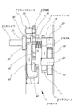
実施例1の駆動源は、図面符号1で示すロータリーソレノイドを用いている。該ロータリーソレノド1は、全体を収納する筐体の一部を構成するリアプレート2に取り付けた電磁コイル10と、該電磁コイル10とエアギャップをもって配置したロータ11とから成る。該ロータ11は、リアプレート2に取り付けたロータ軸受20で上記電磁コイル10の上位において回転自在に支持している。また、該ロータ11には、互いに異なる磁極面をもって電磁コイル10側に向けて露出させた2個のマグネット12を、回転方向に並べて内蔵している。これらの2つのマグネット12、12を被うフロント方向側の面には、バックヨーク13を当接状に付設している。該ロータ11には、その出力軸3を軸対称の位置で該出力軸3に沿ってフロント方向へ延びる平行2本の丸棒状の嵌入ピン14を一体形成している。
The drive source of the first embodiment uses a rotary solenoid indicated by
これにより、ロータ11は、電磁コイル10への通電制御により、同軸上の出力軸3を中心として所定の回転角で往復回転する。このとき、ロータ11は、その回転軸となる出力軸3が図面視で上位に寄った位置にあるため、振り子が揺れるような動き(揺動)を呈することとなる。なお、このようなロータ11の基体的構成は、前記特許文献1などで既に開示しており公知の技術である。
Thereby, the
この構成での往復回転の回転角θは、正面図視で電磁コイル10の両側のリアプレート2の縁部に立設形成したストッパ21への当接規制で決まる。このストッパ21は、リアプレート2の縁部の一部をフロント方向に折り曲げて形成している。このときの回転角θは、ロータ軸受20と両側ストッパ21、21との位置関係によって決まる。実施例1ではこれを30度となるように設定している。なお、実施例1のストッパ21は、上記のようにリアプレート2と同体成形しているが、これを別体に形成としてもよい。両側ストッパ21、21の間隔距離とロータ11の回転半径の如何によって、所望の回転角θを設定することができる。
(2)切替連結機構の構成と作用
The rotational angle θ of the reciprocating rotation in this configuration is determined by the restriction of contact with the
(2) Configuration and operation of the switching coupling mechanism
次に、図面符号4は回転板である。該回転板4は、硬質円盤状を成し、その中央部には、後述する出力シャフト8のリア方向の一端側が適合して挿通し得る口径の軸心孔40を形成している。該軸心孔40の内周面には、後述するキー80が適合しかつ挿通し得る形状のキー溝41を形成している。
また、回転板4の板面には、表裏貫通した複数個の嵌入孔42、・・・を、軸心から所定半径の円周上に等間隔で配列形成している。この間隔距離とその嵌入孔42の半径とで成す角(上記「移行角」と同義)αは、前記ロータ11の回転角θと一致するように設定している。実施例1の回転板4では、1回の移行角を30度に設定しているため、円周を30度で等分割した12個所に嵌入孔42を形成している。
Further, a plurality of insertion holes 42 penetrating the front and back are arranged on the plate surface of the
なお、上記実施例1の回転板4の輪郭形は、円形の他、正多角形、又は円に外接した多角形状としても良い。
In addition, the outline shape of the
かかる構成により、多数個の嵌入孔42には、前記のロータ11の出力軸3の左右両対称位置に形成した一対の嵌入ピン14が、対応する2個所の嵌入孔42に嵌入して連結状態となる。
With such a configuration, a pair of insertion pins 14 formed in the left and right symmetrical positions of the
また、この回転板4とロータ11の間には、クラッチ機構を構成する拡張付勢手段としてコイルスプリング5を、該出力軸3上に環装状態で配設している。このコイルスプリング5は、回転板4をロータ11から離隔させる方向の拡張力として機能する。
In addition, a coil spring 5 is disposed between the
また、回転板4のフロント方向には、クラッチ機構を構成する作動手段6を配設している。この作動手段6は、てこ作用を利用した機構(「てこ作用」)である。このてこ作用を構成するレバー体60は、正面図視で略U字状に形成し、回転板4とフロントプレート7との間に立設状に配置している。該レバー体60の上端部には、回転板4のフロント面の左右方向の両周縁近傍に当接して、てこ作用の作用点として機能する凸状の当接部61を形成している。
In addition, in the front direction of the
また、該レバー体60の下端部62は、後述するフレーム65を介してフロントプレート7の下部にリア方向への回動を可能にして取り付けて、てこ作用の支点として機能するようにしている。
Further, the
さらに、フロントプレート7には、上記レバー体60の下端部62の取り付け位置より上位に寄った位置に、フレーム65で挟持するようにしてソレノイド63を取付け保持している。このソレノイド63は、リア方向へ進退移動(直動)するプランジャ64を備えている。このプランジャ64の直動力は、フレーム65を貫通して、上記レバー体60の支点位置より上位に寄った位置に連結して、てこ作用の力点として機能するようにしている。
Furthermore, a
この構成により、ソレノイド63を起動するとプランジャ64が進出して(矢印aのリア方向)レバー体60を押し、てこ作用によってレバー体60の当接部61が、回転板4のフロント面に押圧力が作用する(矢印b)。この作用によって回転板4は、前記コイルスプリング5を撓ませながらリア方向へ移動する(矢印c)と共に、ロータ11と一体の嵌入ピン14が対応した嵌入孔42に嵌入することとなる。これにより、回転板4はロータ11と連結して同軸上を一体回転する。
With this configuration, when the
次に、前記プランジャ64を戻す(矢印aのフロント方向移動)と、回転板4への押圧が解除され、これに対向してコイルスプリング5の反発作用して回転板4はフロント方向に移動することとなる(矢印d)。これにより嵌入孔42から嵌入ピン14が引き出されて、ロータ11と回転板4との連結が解除され、分離状態となる。
(3)出力手段の構成と作用
Next, when the
(3) Configuration and operation of output means
次に図面符号8は、出力手段を構成する出力シャフトである。該出力シャフト8は、その主体が丸棒状を成し、フロントプレート7に取り付けたフロント軸受71によって貫通状に支持して、ロータ11の出力軸3と同軸上に配置している。また、該出力シャフト8のリア方向の端部には、リア方向に伸びる略コ字状のキー80を一体形成している。
さらに、フロントプレート7の上部には、前記回転板4の少なくとも一つの嵌入孔42に対応した位置に、嵌入可能なストッパーピン72をリア方向へ突出状にして設けている。このストッパーピン72は、嵌入孔42へ嵌入して回転板4を停止するためのものである。したがって、回転板4を停止して保持し得るものであれば、これに限らず他の構成を取ることも可能である。例えば、後述の実施例2のように回転板4の輪郭形を正多角形にして、その周側部を挟持する構成、又は板面に多数の凸部やノッチ部を形成して摩擦や係合で停止させる構成としても良い(図示省略)。
なお、実施例1では、単一のストッパーピン72としているが、これに限定するものではない。
(4)実施例1の全体としての作用と効果
Furthermore, a
In addition, in Example 1, although it is set as the
(4) Operation and effect as a whole of Example 1
上記のように構成した実施例1は、次のように作用する。なお、各機構や作動手段の作用については既述しているので省略する。
本願アクチュエータの特徴は、図5に示したように、出力軸3の正面視において、特定した基準位置(「ホームポジョン(HP)」と言う。)から所定の移行角α単位で移行した複数位置(「マルチポジション」と言う。)で、回転角θの往復回転運動の回転力を駆動力として外部へ出力することにある。このポジションの移行の作用を「モード切替」と言う。
a.連結による回転力の出力
The first embodiment configured as described above operates as follows. Note that the operation of each mechanism and operating means has already been described, and will be omitted.
As shown in FIG. 5, the actuator of the present application is characterized by a plurality of positions shifted in units of a predetermined transition angle α from a specified reference position (referred to as “home position (HP)”) in a front view of the
a. Output of rotational force by connection
図2に示したように、回転板4は、ソレノイド63の起動及びレバー体60の作用によってリア方向(矢印c)に移動してロータ11と連結する。なお、この行程において、出力シャフト8のキー80は、回転板4のキー溝41内を摺動するがキー溝41から外れることは無いため、出力シャフト8と回転板4とは連結状態を維持している。この状態でロータ11、回転板4、及び出力シャフト8は、同軸上で一体回転して、ロータ11からの往復回転力はそのまま出力される。
b.連結解除によるモード切替
As shown in FIG. 2, the
b. Mode switching by disconnection
次に、図3に示したように、ソレノイド63を停止させてプランジャ64を戻す(フロント方向への移動)とレバー体60の回転板4への押圧負荷が無くなり、コイルスプリング5の反発力(拡張力)によって回転板4は、フロント方向へ移動する(矢印d)。移動した回転板4は、ストッパーピン72の嵌入孔42への嵌入によって回転が停止する。回転板4との連結が解除されたロータ11は、単独で往復回転運動が許容されることとなる。
c.モード切替によるポジションの移行
Next, as shown in FIG. 3, when the
c. Position shift by mode switching
次に、図6を用いて、上記作用によるモード切替によるポジションの移行ついて段階を追って説明する。 Next, with reference to FIG. 6, the transition of the position by the mode switching by the above action will be described step by step.
先ず、図6の[HP−1]及び[HP−2]に示すようにホームポジションの状態では、ロータ11の嵌入ピン14が回転板4の対向した嵌入孔42に嵌入(黒塗り図示)し、ストッパーピン72は回転板4から外れて(白抜き図示)、ロータ11、回転板4、及び出力シャフト8が一体となって回転する。この時の往復回転の回転角θは、リアプレート2の両側に設けたストッパ21への当接によって規定される。実施例1においては回転角θが30度となるように設定されている。
First, as shown in [HP-1] and [HP-2] in FIG. 6, in the state of the home position, the
次に、図6の[M−1]に示すように、先ずロータ11が右側ストッパ21Rに当接した状態でロータ11の回転を停止させる。そして、上述したてこ作用によって回転板4は、フロント方向(図面6視で手前方向)に移動し、ストッパーピン72が回転板4の対向した嵌入孔42に嵌入(黒塗り図示)して停止する。これに伴ってロータ11の嵌入ピン14は、嵌入孔42から抜き出される(白抜き図示)。この状態では、ロータ11は単独回転が許容されるため、図6の[M−2]に示すようにロータ11のみを左側ストッパ21Lに当たるまで時計方向に回転(矢印e)させる。この時の回転角は、ロータ11の回転角α(実施例1では30度)となる。
Next, as shown in [M-1] in FIG. 6, the rotation of the
次に、この状態で、回転板4をリア方向(図面6視で奥側方向)に移動させると、ストッパーピン72は回転板4から外れ(白抜き図示)、同時に、ロータ11の嵌入ピン14は対向した嵌入孔42に嵌入(黒塗り図示)して、回転板4とロータ11とが再連結する。これにより出力シャフト8からは、次のポジション(「2nd.ポジション」)に移行した位置において、往復回転力が出力される(図6の[SP−1]及び[SP−2])。この2nd.ポジションは、図面6視で、ホームポジションから反時計方向にθ(本実施例では30度)だけ移行した位置となる。
Next, in this state, when the
このような行程を経て、モード切替を順次行うことにより、所望のポジションまで移行させて、往復回転力を出力させることができる。このポジションの移行角αは、通常はロータ11の回転角θと同じに設定されるが、ロータ11を左右ストッパ21の当接位置以外(例えば、中間位置)で停止させることにより、さらに細分割した移行角αを設定することも可能である。因みに、実施例1では、移行角αを30度に選定しているため、往復回転の回転力を出力させるポジションは、1周回の12箇所となる。
By sequentially switching the modes through such a process, it is possible to shift to a desired position and output a reciprocating rotational force. The transition angle α of this position is normally set to be the same as the rotation angle θ of the
次に、実施例2について説明する。
実施例2は、実施例1と同様に本願アクチュエータの技術的思想を実現するものであるが、上記した実施例1のクラッチ機構の作動手段において、さらなる構成要素を付加したことにある。その概要は、新たに切替板200を設け、実施例1の回転板4に代わってこの切替板200を、出力軸3と同軸上を移動させてモード切替を行うようにしたものである。
Next, Example 2 will be described.
In the second embodiment, the technical idea of the actuator of the present application is realized in the same manner as the first embodiment, but a further component is added to the operation mechanism of the clutch mechanism of the first embodiment. The outline is that a
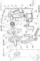
図7〜図11は、実施例2に関して示した図である。なお、以下の説明においては、重複説明を避けるため、実施例1と同様な機能を奏する構成要素については、実施例1で用いた図面符号を付して詳細な説明を省略する。
(1)駆動源の構成
7-11 is the figure shown regarding Example 2. FIG. In the following description, components having the same functions as those in the first embodiment are denoted by the same reference numerals as those used in the first embodiment, and detailed description thereof is omitted to avoid redundant description.
(1) Configuration of drive source
実施例2のロータリーソレノド100の基本構成は、実施例1と同様であるが、ロータ11の回転中心にロータシャフト110を設けている点で異なる構成を取っている。これは、後述する切替板200の出力軸上への保持と移動軸を確保するためである。その他のロータ11、嵌入ピン14、及びリアプレート2の構成、並びにこれらの作用は実施例1と同様である。
(2)切替機構の構成と作用
The basic configuration of the
(2) Configuration and operation of the switching mechanism
図面符号200で示した切替板は、硬質で矩形板状を成し、その中央部には、前記ロータシャフト110が適合して貫通し得る口径を持った挿通孔210を形成している。また、切替板200のリア方向の板面には、前記挿通孔210を挟む左右対称位置に、ロータ11の嵌入ピン14が挿通し得る開口径と摺動距離をもった挿通管211を、一体的に形成している。さらに、切替板200のフロント方向の板面には、前記挿通孔210を挟む上下対称位置に、回転板400の嵌入孔410に挿通可能な外径を持った連結ピン212を一体的に形成している。
A switching plate denoted by
実施例2で用いる前記回転板400は、硬質板状を成し、その板面には実施例1と同様に多数の嵌入孔410、・・・を円周上に等間隔では形成している。回転板400の輪郭形は、正多角形(実施例2では正12角形)に形成している。この角数は前記嵌入孔410の数と一致しており、かつその角部は嵌入孔410の通る半径方向となるように形成している。また、実施例2の回転板400は、その軸心にフロント方向に延びる出力シャフト8を一体的に取付け固定して、フロント軸受71で回動自在に支持している。前記嵌入孔410には、上記切替板200の対応する連結ピン212が適合嵌入して連結する。
The rotary plate 400 used in the second embodiment has a hard plate shape, and a large number of
該回転板400と切替板200との間には、クラッチ機構を構成する作動手段600を配設している。この作動手段600は、実施例1と同様、てこ作用で機能する構成を取っている。
Actuating means 600 constituting a clutch mechanism is disposed between the rotating plate 400 and the
回転板400の下方には、略U字状を呈したストッパ体620を立設状に配置している。該ストッパ体620は、該U字状の一部を構成する平行体からなる挟持部621(図面視で立設状態)を主体としており、その間隔は、回転板400が正多角形の輪郭形である場合は、その対向する辺部を挟む距離に設定している。また、挟持部621の下端部のリア側には、上部にリア方向へ下降傾斜した斜面を有するくさび体622を一体的に形成している。
Under the rotating plate 400, a
てこ作用の構成として、ストッパ体620の下端部にリンクレバ610の一端側(フロント方向端部)を回動自在にして結合(「リンク結合」)して、作用点として機能させている。
As a configuration of the lever operation, one end side (front end portion) of the
また、該リンクレバ610の他端側(リア方向端部)は、リアプレート2の下部に取付け固定したにフレーム630を介してリンク結合させて、てこ作用の支点として機能させている。
さらに、リアプレート2の下端部付近には、その下端縁部を折り曲げ成形したベース板640に、プランジャ64の直動方向を上に向けたソレノイド63を載置し、かつ前記フレーム630によって覆うようにして固定している。そしてプランジャ64は、当該フレーム630を貫通して進退してリンクレバ610の中間部に作用することによって、てこ作用の力点として機能させている。
Further, the other end side (rear direction end portion) of the
Further, in the vicinity of the lower end portion of the
上記構成により、図8に示すように、ソレノイド63を起動させるとプランジャ64が上昇進出してリンクレバ610の前記一端側を押し上げると、これとリンク結合したストッパ体620がてこ作用によって垂直に上昇する。これに従って、ストッパ体620の挟持部621が、回転板400の対向する外周側面を当接摺動して適合(「挟持」)することとなる。この上昇と共にストッパ体620と一体のくさび体622が、回転板400と切替板200との間に介入して押し広げて互いを離隔させることとなる。この離隔距離はくさび体622の厚さで決まるが、その厚さは回転板400の嵌入孔410から切替板200の連結ピン212が、完全に抜き出せる距離に設定している。
With the above configuration, as shown in FIG. 8, when the
これにより、切替板200は、ロータシャフト110上をコイルスプリング5を撓ませながらリア方向へ摺動する。この時、コイルスプリング5には拡張反発力が蓄積される。
As a result, the switching
これとは逆に、図9に示すように、ソレノイド63の起動を停止させてプランジャ64を戻す(下降)と、ストッパ体620は、上記てこ作用の反対作用によって下降して回転板400から離隔し、該回転板400は停止状態から開放される。これと同時に、前記くさび体622の介在が解消して回転板400と切替板200との離隔の強制力が無くなる。これに対向して、前記コイルスプリング5が反発して拡張力が作用し、切替板200の連結ピン212が対応する回転板400の嵌入孔410に嵌入する。この場合、ロータ11の嵌入ピン14は、切替板200が移動しても長さのある挿通管211内に滞在して外れることは無い。
(3)出力手段の構成と作用
On the other hand, as shown in FIG. 9, when the activation of the
(3) Configuration and operation of output means
実施例2における出力手段を構成する出力シャフト8は、実施例1と同様に本体が棒状体を成し、前記回転板400の軸心に一体として固定的に取り付けて成り、フロント軸受71によって、ロータシャフト110の出力軸3と同軸上に支持している。出力シャフト8は、回転板400の回転をそのまま伝達して出力させる。
(4)実施例2の構成のポジションの全体としての作用と効果
In the
(4) Operation and effect as a whole of the position of the configuration of the second embodiment
次に、図11を用いて、実施例2における、モード切替によるポジションの移行ついて段階を追って説明する。 Next, with reference to FIG. 11, the transition of the position by mode switching in the second embodiment will be described step by step.
先ず、図11の[HP−1]及び[HP−2]に示すようにホームポジションの状態では、ロータ11と一体回転する切替板200の連結ピン212が回転板400の嵌入孔410に嵌入(黒塗り図示)し、ストッパ体620は下降して回転板400から外れて、ロータ11、切替板200、回転板400、及び出力シャフト8が一体となって回転する。この時の往復回転の回転角θは、リアプレート2の両側のストッパ21への当接によって規定されている。この角度θは、実施例1と同様に30度に設定されている。
First, as shown in [HP-1] and [HP-2] in FIG. 11, in the home position state, the connecting
次に、図11の[M−1]に示すように、ロータ11が正面視右側に振れた状態で停止させると共に、前記てこ作用によって上昇して来たストッパ体620が、回転板400の対向辺を挟持して回転を停止させる。それと共にストッパ体620のくさび体622が、回転板400と切替板200の間に挿入介在し、連結ピン212が嵌入孔410から引き出される。この状態では、ロータ11と切替板200のみが一体回転可能となる。ここで、図11の[M−2]に示すようにロータ11及び切替板200を、左側ストッパ21Lに当接するまで時計方向に回転(矢印e)させる。この時の回転角は、ロータ11の回転角α(実施例2では30度)となる。
Next, as shown in [M-1] in FIG. 11, the
次に、この状態を維持して、ストッパ体620を下降させると回転板400の挟持が解消し、かつくさび体622も同時に下降するため回転板400と切替板200とが再連結することとなる。これにより出力シャフト8からは、次のポジション(「2nd.ポジション」)に移行した位置で往復回転力が出力される(図11[SP−1]及び[SP−2])。この場合の2nd.ポジションは、図面11視で、ホームポジションから反時計方向にθ(本実施例では30度)だけ移行した位置となる。
Next, when this state is maintained and the
このような行程を経てモード切替を繰り返すことにより、複数個所(マルチポジション)において、それぞれ往復回転力を出力させることができる。 By repeating the mode switching through such a process, it is possible to output the reciprocating rotational force at each of a plurality of locations (multi-position).
1 ロータリーソレノイド
11 ロータ
14 嵌入ピン
2 リアプレート
21 ストッパ
3 出力軸
4 回転板
42 嵌入孔
5 コイルスプリング
6 作動手段
60 レバー体
63 ソレノイド
7 フロントプレート
72 ストッパーピン
8 出力シャフト
100 ロータリーソレノイド
110 ロータシャフト
200 切替板
212 連結ピン
400 回転板
410 嵌入孔
600 作動手段
610 リンクレバ
620 ストッパ体
622 くさび体
DESCRIPTION OF
Claims (9)
該駆動源の出力軸と同軸上で連結分離させると共に、該分離時に前記駆動源の出力軸に対して同軸上で相対的に軸回転させて連結する切替連結機構と、
該切替連結機構を介した前記軸出力を外部へ供給する出力手段と、
から成り、
前記切替連結機構は、
前記駆動源の出力軸と複数の相対的軸回転位置で連結することを可能とした回転板と、
該回転板と前記駆動源とを連結分離させるクラッチ機構と、
該クラッチ機構による分離時に前記回転板の回転を停止させるストッパ手段と、
から構成したことを特徴とするマルチポジション型往復回転アクチュエータ。 A drive source that axially outputs a rotational force that reciprocates at a predetermined rotation angle;
A switching connection mechanism that is connected and separated on the same axis as the output shaft of the drive source, and that is connected to the output axis of the drive source by rotating the shaft relative to the output axis of the drive source.
Output means for supplying the shaft output to the outside via the switching connection mechanism;
Ri consists of,
The switching coupling mechanism is
A rotating plate capable of being connected to the output shaft of the drive source at a plurality of relative shaft rotation positions;
A clutch mechanism for connecting and separating the rotating plate and the drive source;
Stopper means for stopping rotation of the rotating plate at the time of separation by the clutch mechanism;
Multi-position type reciprocating rotary actuator characterized by being configured from.
前記駆動源と前記回転板との間に介在させた拡張付勢手段と、Expansion biasing means interposed between the drive source and the rotating plate;
前記回転板を軸に沿ってかつ前記拡張付勢手段を圧縮する方向に移動させる作動手段と、An actuating means for moving the rotating plate along an axis and in a direction for compressing the expansion biasing means;
から成ることを特徴とする請求項1記載のマルチポジション型往復回転アクチュエータ。The multi-position reciprocating rotary actuator according to claim 1, comprising:
該駆動源の出力軸と同軸上で連結分離させると共に、該分離時に前記駆動源の出力軸に対して同軸上で相対的に軸回転させて連結する切替連結機構と、A switching connection mechanism that is connected and separated on the same axis as the output shaft of the drive source, and that is connected to the output axis of the drive source by rotating the shaft relative to the output axis of the drive source.
該切替連結機構を介した前記軸出力を外部へ供給する出力手段と、Output means for supplying the shaft output to the outside via the switching connection mechanism;
から成り、Consisting of
前記切替連結機構は、The switching coupling mechanism is
前記駆動源の出力軸と同軸回転で連結した切替板と、A switching plate connected coaxially with the output shaft of the drive source;
該切替板と複数の相対的軸回転位置で連結する回転板と、A rotating plate coupled to the switching plate at a plurality of relative axial rotation positions;
前記切替板を介して該回転板と前記駆動源とを連結分離させるクラッチ機構と、A clutch mechanism for connecting and separating the rotary plate and the drive source via the switching plate;
該クラッチ機構による分離時に前記回転板の回転を停止させるストッパ手段と、Stopper means for stopping rotation of the rotating plate at the time of separation by the clutch mechanism;
から構成したことを特徴とするマルチポジション型往復回転アクチュエータ。A multi-position type reciprocating rotary actuator characterized by comprising
前記駆動源と前記切替板との間に介在させた拡張付勢手段と、Expansion biasing means interposed between the drive source and the switching plate;
前記切替板を軸に沿ってかつ前記拡張付勢手段を圧縮する方向に移動させると共に、該切替板と回転板とを連結分離させる作動手段と、An operating means for moving the switching plate along an axis and in a direction for compressing the expansion biasing means, and for connecting and separating the switching plate and the rotating plate;
から成ることを特徴とする請求項3記載のマルチポジション型往復回転アクチュエータ。The multi-position type reciprocating rotary actuator according to claim 3, comprising:
前記駆動源の回転角と同一であることを特徴とする請求項1、又は3記載のマルチポジション型往復回転アクチュエータ。4. The multi-position reciprocating rotary actuator according to claim 1, wherein the multi-position reciprocating rotary actuator has the same rotation angle as the driving source.
直動アクチュエータの前記回転板への直接作用、てこ作用、又はリンク機構によるものであることを特徴とする請求項2、又は4記載のマルチポジション型往復回転アクチュエータ。The multi-position reciprocating rotary actuator according to claim 2 or 4, wherein the multi-position reciprocating rotary actuator is based on a direct action, a lever action, or a link mechanism of the linear actuator on the rotary plate.
少なくとも回転方向を規制する結合であることを特徴とする請求項1から6のいずれか記載のマルチポジション型往復回転アクチュエータ。The multi-position reciprocating rotary actuator according to any one of claims 1 to 6, wherein the multi-position type reciprocating rotary actuator is at least a coupling that regulates a rotation direction.
凹部と凸部との嵌合であることを特徴とする請求項7記載のマルチポジション型往復回転アクチュエータ。The multi-position reciprocating rotary actuator according to claim 7, wherein the concave portion and the convex portion are fitted.
円形又は円が内接する多角形状の回転板に、軸心から所定半径の円周上に等間隔で形成した多数個の凹部又は凸部と、A plurality of concave or convex portions formed at equal intervals on the circumference of a predetermined radius from the axis, on a polygonal rotating plate inscribed in a circle or a circle,
前記回転板と対向する駆動源の出力側又は切替板に形成した凸部又は凹部との嵌合であることを特徴とする請求項8記載のマルチポジション型往復回転アクチュエータ。9. The multi-position reciprocating rotary actuator according to claim 8, wherein the actuator is fitted with a convex portion or a concave portion formed on the output side of the driving source facing the rotary plate or the switching plate.
Priority Applications (1)
| Application Number | Priority Date | Filing Date | Title |
|---|---|---|---|
| JP2014012872A JP6301661B2 (en) | 2014-01-27 | 2014-01-27 | Multi-position reciprocating rotary actuator |
Applications Claiming Priority (1)
| Application Number | Priority Date | Filing Date | Title |
|---|---|---|---|
| JP2014012872A JP6301661B2 (en) | 2014-01-27 | 2014-01-27 | Multi-position reciprocating rotary actuator |
Publications (2)
| Publication Number | Publication Date |
|---|---|
| JP2015142400A JP2015142400A (en) | 2015-08-03 |
| JP6301661B2 true JP6301661B2 (en) | 2018-03-28 |
Family
ID=53772433
Family Applications (1)
| Application Number | Title | Priority Date | Filing Date |
|---|---|---|---|
| JP2014012872A Active JP6301661B2 (en) | 2014-01-27 | 2014-01-27 | Multi-position reciprocating rotary actuator |
Country Status (1)
| Country | Link |
|---|---|
| JP (1) | JP6301661B2 (en) |
Families Citing this family (2)
| Publication number | Priority date | Publication date | Assignee | Title |
|---|---|---|---|---|
| CN111884440A (en) * | 2020-07-29 | 2020-11-03 | 深圳市鹏翔运达机械科技有限公司 | Reciprocating circulation type horizontal pushing mechanism and rotor alignment equipment |
| CN115138801B (en) * | 2022-06-30 | 2024-02-13 | 瑞安市东弘电器有限公司 | Copper bar extrusion production device and production method thereof |
Family Cites Families (2)
| Publication number | Priority date | Publication date | Assignee | Title |
|---|---|---|---|---|
| JP4302502B2 (en) * | 2003-12-11 | 2009-07-29 | Ntn株式会社 | Clutch unit |
| JP5405894B2 (en) * | 2008-05-13 | 2014-02-05 | 沖マイクロ技研株式会社 | Reciprocating rotary actuator |
-
2014
- 2014-01-27 JP JP2014012872A patent/JP6301661B2/en active Active
Also Published As
| Publication number | Publication date |
|---|---|
| JP2015142400A (en) | 2015-08-03 |
Similar Documents
| Publication | Publication Date | Title |
|---|---|---|
| JP5882946B2 (en) | Swivel actuator | |
| JP5315421B2 (en) | Valve train switching device | |
| JP5164545B2 (en) | Valve operating device and rocker arm unit | |
| CN113302572A (en) | Pedal emulator for a vehicle | |
| JP2007032556A (en) | Valve gear of internal combustion engine | |
| CN104185573B (en) | Resetting means and motor vehicles for the steering-column switch system of motor vehicles | |
| EP1705408A2 (en) | Manual transmission | |
| JP6301661B2 (en) | Multi-position reciprocating rotary actuator | |
| JP2007040238A5 (en) | ||
| CN102468077A (en) | Switch operating device | |
| JP6621552B2 (en) | Staple gun | |
| KR101418822B1 (en) | Clutch Actuator | |
| US20170004943A1 (en) | Actuator for a vacuum switch tube of a switching assembly of a tap changer | |
| CN108027626B (en) | Pedal device with actuation damping | |
| CN112041190B (en) | Vertical pedal for vehicle | |
| CN111463033A (en) | Automatic transfer switch and method thereof | |
| WO2016125246A1 (en) | Multi-position type reciprocating rotary actuator | |
| CN104100660A (en) | Dry dual clutch transmission actuation system using electrical motor with force aided lever | |
| JP5088895B2 (en) | Electrical switch element having a rotary lever switch mechanism, in particular a relay | |
| US20190358535A1 (en) | Game machine and gear shifting device capable of alternatively changing gear operation modes | |
| KR100803294B1 (en) | Apparatus for Actuating a Diaphram Spring Installed in a Clutch Housing | |
| EP2141395A1 (en) | Valve core position controlling device | |
| WO2015098327A1 (en) | Magnetic switch, and starter equipped with same | |
| JP4675687B2 (en) | Limit switch | |
| CN220335446U (en) | Driving adjustment of sewing machine |
Legal Events
| Date | Code | Title | Description |
|---|---|---|---|
| A621 | Written request for application examination |
Free format text: JAPANESE INTERMEDIATE CODE: A621 Effective date: 20161201 |
|
| A131 | Notification of reasons for refusal |
Free format text: JAPANESE INTERMEDIATE CODE: A131 Effective date: 20170731 |
|
| A977 | Report on retrieval |
Free format text: JAPANESE INTERMEDIATE CODE: A971007 Effective date: 20170731 |
|
| A521 | Request for written amendment filed |
Free format text: JAPANESE INTERMEDIATE CODE: A523 Effective date: 20170922 |
|
| TRDD | Decision of grant or rejection written | ||
| A01 | Written decision to grant a patent or to grant a registration (utility model) |
Free format text: JAPANESE INTERMEDIATE CODE: A01 Effective date: 20180202 |
|
| A61 | First payment of annual fees (during grant procedure) |
Free format text: JAPANESE INTERMEDIATE CODE: A61 Effective date: 20180301 |
|
| R150 | Certificate of patent or registration of utility model |
Ref document number: 6301661 Country of ref document: JP Free format text: JAPANESE INTERMEDIATE CODE: R150 |
|
| R250 | Receipt of annual fees |
Free format text: JAPANESE INTERMEDIATE CODE: R250 |
|
| R250 | Receipt of annual fees |
Free format text: JAPANESE INTERMEDIATE CODE: R250 |
|
| R250 | Receipt of annual fees |
Free format text: JAPANESE INTERMEDIATE CODE: R250 |
|
| R250 | Receipt of annual fees |
Free format text: JAPANESE INTERMEDIATE CODE: R250 |