JP6297510B2 - Door interlock device - Google Patents
Door interlock device Download PDFInfo
- Publication number
- JP6297510B2 JP6297510B2 JP2015015413A JP2015015413A JP6297510B2 JP 6297510 B2 JP6297510 B2 JP 6297510B2 JP 2015015413 A JP2015015413 A JP 2015015413A JP 2015015413 A JP2015015413 A JP 2015015413A JP 6297510 B2 JP6297510 B2 JP 6297510B2
- Authority
- JP
- Japan
- Prior art keywords
- door
- interlock
- sub
- rod
- main door
- Prior art date
- Legal status (The legal status is an assumption and is not a legal conclusion. Google has not performed a legal analysis and makes no representation as to the accuracy of the status listed.)
- Expired - Fee Related
Links
Images


Description
本発明は、制御盤などの筐体において、開閉可能な扉のインターロック装置であって、特に、1または2以上の扉のうち主扉を開けないと、副扉を開けられない構造のインターロック装置の改良に関する。 The present invention relates to an interlock device for a door that can be opened and closed in a housing such as a control panel, and in particular, an interface having a structure in which a sub door cannot be opened unless a main door is opened among one or more doors. The present invention relates to an improvement of a locking device.
複数の開き扉付きの制御盤において、一部の制御盤は、安全の観点から、主扉を開けないと、副扉を開けられず、主扉を開けると、副扉も開けられる構造のものとして製作されている。 Among control panels with multiple doors, for safety reasons, some control panels have a structure in which the sub door cannot be opened unless the main door is opened, and the sub door can be opened when the main door is opened. It is produced as.
例えば特許文献1は、制御盤の複数の扉について、主制御盤の扉を開けると、これに連動して他の扉を開けられる状態となる、インターロック装置を開示している。そのインターロック装置は、主制御盤の扉の動きをベルクランク状のリンクにより移動ロッドの移動に変換し、移動ロッドの移動により拘束部材を回動により変移させ、拘束部材と他の制御盤の扉の引掛部との係り合いを外して、他の扉を開けられようにしている。そのインターロック装置は、他の制御盤の扉ごとに、拘束部材を軸により回動自在に支持し、この拘束部材を扉の引掛部に係り合わせているため、他の制御盤の扉の部分が複雑であり、制御盤や多連式の扉に組み込みにくい構造となっている。
For example,
また、特許文献2は、筐体のインターロック機構において、筐体の2つの扉について、一方の扉を開けたときに、ばねに抗してスライド部材を移動させ、スライド部材の移動によって、他方の扉のロックを解除する、ことを開示している。しかし、そのインターロック機構は、基本的に2枚構成の扉に適用する構造であるため、多連式の扉にそのまま適用できず、構造的にも複雑になる。
Further, in
したがって、本発明の解決課題は、簡単な構造で、多連式の扉に適用できる扉のインターロック装置を提供することである。 Therefore, the problem to be solved by the present invention is to provide a door interlock device that has a simple structure and can be applied to multiple doors.
上記の課題のもとに、本発明は、筐本体の開口位置に主扉および1または2以上の副扉をヒンジによって開閉自在に取り付けられている筐体において、主扉の開閉動作に連動する操作手段と、副扉に対応する位置で筐本体に移動自在に支持され、スプリングにより付勢され、操作手段の動きに連動して移動するインターロック棒と、副扉に対応する位置でインターロック棒に取り付けられているインターロック金具と、副扉に取り付けられ、副扉のハンドルの操作によって筐本体に係り合うロック棒と、ロック棒に設けられ、インターロック金具に係り合うストッパとからなる扉のインターロック装置であって、主扉の閉状態のときに、主扉の閉動作に連動する操作手段により、インターロック棒を係り合い方向に移動させることにより、インターロック金具をストッパに係り合わせ、インターロック棒の移動を阻止して、副扉の開操作を禁止し、また主扉の開状態のときに、主扉の開動作に連動する操作手段によって、インターロック棒を解除方向に移動させることにより、ストッパに対するインターロック金具の係り合いを解除して、副扉の開操作を可能としている。 Based on the above problems, the present invention is interlocked with the opening / closing operation of the main door in a housing in which the main door and one or more sub doors are attached to the opening position of the housing main body by hinges. Interlock rod that is movably supported by the housing body at a position corresponding to the sub-door, urged by a spring, and moves in conjunction with the movement of the operation means, and an interlock at a position corresponding to the sub-door A door composed of an interlock fitting attached to the rod, a lock rod attached to the sub door and engaged with the housing body by operating the handle of the sub door, and a stopper provided on the lock rod and engaged with the interlock fitting. When the main door is in the closed state, the interlock rod is moved in the engaging direction by the operating means interlocking with the closing operation of the main door. The turlock bracket is engaged with the stopper to prevent the interlock rod from moving, prohibiting the opening of the secondary door, and when the main door is in the open state, the operation means linked to the opening operation of the main door By moving the lock rod in the release direction, the interlock metal fitting with respect to the stopper is released, and the sub door can be opened.
また、本発明は、上記の扉のインターロック装置において、操作手段を主扉の背面に固定されている操作カムによって構成し、インターロック棒を操作カムのカムフォロアとして機能させている。 Further, according to the present invention, in the door interlock device described above, the operation means is constituted by an operation cam fixed to the back surface of the main door, and the interlock rod functions as a cam follower of the operation cam.
本発明は、上記の扉のインターロック装置において、操作手段を操作レバーにより構成し、操作レバーを筐本体に支持軸により回動自在に取り付け、操作レバーの一端を主扉の背面に当接可能な位置におき、操作レバーの他端をインターロック棒に連動ピンで連結させている。 In the door interlock device according to the present invention, the operation means is constituted by an operation lever, the operation lever is rotatably attached to the housing body by a support shaft, and one end of the operation lever can be brought into contact with the back surface of the main door. The other end of the control lever is connected to the interlock bar with an interlocking pin.
さらに本発明は、上記の扉のインターロック装置において、操作手段を主扉の背面に片持ち状態で固定した操作アームにより構成し、操作アームをインターロック棒のアームピンに係り合わせている。 Further, according to the present invention, in the door interlock device described above, the operation means is constituted by an operation arm fixed in a cantilever state on the back surface of the main door, and the operation arm is engaged with the arm pin of the interlock rod.
そして、本発明は、隣り合う副扉を両開き形式とし、一方の副扉に召し合わせ片を形成し、他方の副扉にのみロック棒を設けている。 In the present invention, adjacent subdoors are of a double door type, a summing piece is formed on one subdoor, and a lock bar is provided only on the other subdoor.
本発明によると、主扉の閉状態のときに、副扉の開操作が禁止されるから、副扉単独での開操作にともなう危険や不都合、例えば主扉側での通電の設定中に、副扉の開放による危険な作業が未然に防止できること、主扉の開閉動作によって、操作手段がインターロック棒のインターロック金具とロック棒のストッパとの係り合わせや解除を操作するため、インターロッ棒の移動のために、特別な駆動手段が不要となること、さらに操作手段に連動するインターロック棒、インターロック金具などが簡単な構成であることから、筐体に対して扉のインターロック装置の組み込みが容易であり、多連式の扉でも単純な構成のものとして組み立てられること、などの効果が得られる。 According to the present invention, when the main door is closed, the opening operation of the sub door is prohibited, so there are dangers and inconveniences associated with the opening operation of the sub door alone, for example, during energization setting on the main door side, that dangerous work by opening the Fukutobira can be prevented in advance, by the opening and closing operation of the main door, since the operation means is operated the engagement alignment and releasing the stopper of the interlock bracket and locking bar interlock rods, interlock No special driving means is required to move the bar, and the interlock bar, interlock fittings, etc. that are linked to the operating means have a simple structure. Can be easily assembled, and even a multiple door can be assembled as a simple structure .
また、操作手段が主扉の背面に固定されている操作カムによって構成されていると、カムフォロアとなるインターロック棒が簡単に移動させることができ、主扉の開度に対するインターロック棒の移動量もカム形状の設計により適切に設定できる。 In addition, if the operating means is composed of an operating cam fixed to the back of the main door, the interlock rod as the cam follower can be easily moved, and the amount of movement of the interlock rod relative to the opening of the main door Can also be set appropriately by the cam shape design.
操作手段が操作レバーにより構成されていると、構造が簡単であり、インターロック棒の移動量もレバー比により適切に設定できる。 If the operating means is constituted by an operating lever, the structure is simple, and the amount of movement of the interlock rod can be appropriately set by the lever ratio.
さらに操作手段が主扉の背面に片持ち状態で固定した操作アームにより構成されていると、構造が簡単であり、インターロック棒の移動が確実となる。 Further, when the operation means is constituted by an operation arm fixed in a cantilever state on the back surface of the main door, the structure is simple and the movement of the interlock rod is ensured.
そして、隣り合う副扉を両開き形式とすれば、1つの副扉についてロック棒やインターロック金具などが省略でき、その分、構成が簡略化できる。 Then, if the adjacent sub doors are of a double door type, a lock rod, an interlock fitting, etc. can be omitted for one sub door, and the configuration can be simplified accordingly.
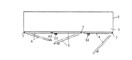
図1および図2は、本発明に係る扉のインターロック装置1の組み込み対象の筐体2を示している。これらの図において、筐体2は、例えば3連式扉の制御盤であって、前面開口型の筐本体3によって構成されている。筐本体3は、前面の開口位置で一例として1つの主扉4および2つの副扉5、6を有している。
1 and 2 show a
主扉4は、筐本体3の一方の側面に対して上下のヒンジ7により片開き可能な状態として開閉自在に取り付けられている。また副扉5、6は、筐本体3の中間位置の枠の部分、筐本体3の他方の側面に対して、それぞれ上下のヒンジ7により両開き可能な状態として開閉自在に取り付けられている。この具体例において、左側の副扉6は、開き側に召し合わせ片6aを有しており、右側の副扉5は、閉状態で召し合わせ片6aの正面側の面つまり外側面に当たることによって、両者間の隙間を閉じるとともに、副扉6単独での開く方向への動きを阻止している。主扉4および副扉5は、ともに開閉操作のためにハンドル12、13を有している。
The
次に、図3、図4および図5は、上記の筐体2に組み込む扉のインターロック装置1の要部を示している。これらの図において、扉のインターロック装置1は、主要の構成部品として操作手段8、インターロック棒10、インターロック棒10のインターロック金具11、ロック棒14およびロック棒14のストッパ15を有している。
Next, FIGS. 3, 4, and 5 show a main part of the
操作手段8は、主扉4の開閉動作に連動してインターロック棒10を移動させる部分であり、図3および図4の具体例において、主扉4の背面に固定されている円弧状の操作カム16により構成され、インターロック棒10を操作カム16のカムフォロアとして機能させている。操作カム16は、主扉4の開閉動作にともなって、ヒンジ7を中心とする円弧運動によって、円弧状のカム面でインターロック棒10の先端に当接する位置にある。なお図示しないが、インターロック棒10の先端に必要に応じて摩擦低減用のローラが設けられ、このときローラは、操作カム16のカム面にころがり接触することになる。
The operating means 8 is a part that moves the
インターロック棒10は、主扉4の操作カム16および副扉5に対向する位置において筐本体3に2以上のホルダ17によってインターロック棒10の中心線の方向に移動自在に支持され、1つのホルダ17とインターロック棒10に固定したスプリング受け18との間に設けた圧縮形式のスプリング9によって、図4の矢印の方向(解除方向)に付勢され、筐本体3に固定されている位置規制片19によって適切な位置すなわち操作カム16の動きに応動できる位置で停止するように設けられている。
The
また、インターロック金具11は、副扉5に対応する位置において、インターロック棒10に取り付けられ、ロック棒14に設けられているストッパ15の下方でストッパ15に係り合う位置にあって、一例としてロック棒14を挟むように二股形状となっている。なお、インターロック棒10に対するインターロック金具11の取り付け位置は、セットカラー31によって設定されている。
Further, the
そして、ロック棒14は、図5に示すように、ハンドル13の上方および下方の位置において、副扉5の背面に上下のガイド20によって上下動自在に取り付けられ、副扉5を閉じたときに、副扉5のハンドル13の回動操作によって筐本体3の上下位置のロック孔21に嵌まって、副扉5を開けられない状態とする。ハンドル13は、一例として回動式であり、ハンドル軸22に固定されている回動レバー23とロック棒14とをレバーピン24により連結している。このように、通常、ハンドル13の上方および下方の位置にロック棒14が設けられており、上方のロック棒14は、インターロック金具11の動きに関与するが、下方のロック棒14は、インターロック金具11の動きに関与しないため、省略できる。
As shown in FIG. 5, the
オペレータがハンドル13を図5で時計方向に回動させると、上下のロック棒14は、上下に移動し、その先端部分でロック孔21に嵌まる。このため、副扉5は、回動後のハンドル13の位置では、開けられない状態になる。図5の状態のときのように、インターロック金具11がストッパ15から離れている状態のとき、オペレータがハンドル13を反時計方向に回動させれば、上下のロック棒14は、ロック孔21から抜けるため、副扉5は、開けられる状態となる。なお、回動レバー23の回動によって、レバーピン24がロック棒14の中心線から少しずれるが、この時のずれは、ロック棒14の変形によって吸収されるが、必要ならば、レバーピン24を回動レバー23に対してずれ吸収用の長孔によって連結する。
When the operator rotates the
主扉4の部分でも、図5と同様の構成のロック棒14、ロック孔21、ハンドル12によって操作可能な回動レバー23が設けられるが、主扉4の位置でインターロック金具11は、設けられておらず、主扉4の位置のロック棒14は、ストッパ15を有せず、インターロック金具11の動きに関与しない。したがって、主扉4のハンドル12は、ロック棒14を有しない形式のもの、例えば掛け金やクレセント錠などにより構成することもできる。
The
図3に示すように、主扉4および副扉5が閉状態のときに、操作手段8の操作カム16は、円弧状のカム面でカムフォロアとしてのインターロック棒10の先端に当たり、スプリング9に抗してインターロック棒10を矢印の係り合い方向に移動させることによってインターロック金具11をストッパ15の下方の位置に差し入れ、上側のインターロック棒10の下方への移動を阻止している。このような状態のとき、オペレータは、副扉5のハンドル13を回動操作できず、副扉5を単独で開けることはできない。なお、主扉4の開度に対するインターロック棒10の移動量は、操作カム16のカム形状の設計により適切に設定できる。
As shown in FIG. 3, when the
図4に示すように、オペレータが主扉4のハンドル12を操作し、主扉4を開状態とすると、主扉4の開動作によって、操作カム16は、カムフォロアとしてのインターロック棒10から離れるため、インターロック棒10は、スプリング9の付勢力で矢印の解除方向に移動し、ストッパ15の対するインターロック金具11の係り合いを解除し、副扉5の開操作を可能とする。ここでオペレータが副扉5のハンドル13を操作し、副扉5のロック棒14をロック孔21から外せば、副扉5を開けられ、これに続いて副扉6も開けられる状態となる。このように、主扉4が開状態のときにのみ、副扉5、6は、開操作可能となる。
As shown in FIG. 4, when the operator operates the
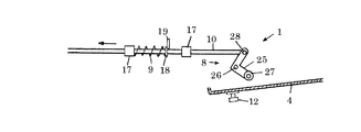
つぎに、図6の具体例は、操作手段8をL字型の操作レバー25により構成する例である。操作レバー25は、筐本体3に支持軸26により回動自在に取り付けられ、一端で主扉4の背面に例えばローラ27により当接し、他端でインターロック棒10に連動ピン28で連結されている。この具体例でも、主扉4が閉じるときに、操作レバー25は、インターロック棒10をスプリング9に抗して矢印の係り合い方向に移動させ、インターロック金具11をストッパ15に係り合わせているが、主扉4が開くと、操作レバー25は、主扉4から離れるため、インターロック棒10は、スプリング9に付勢されて矢印と逆の解除方向に移動し、ストッパ15に対するインターロック金具11の係り合いを解除することになる。この具体例で、連動ピン28は、支持軸26を中心とする円弧上を移動するため、操作レバー25は、必要に応じて長孔により連動ピン28にはまり合う。操作手段8が操作レバー25により構成されていると、構造が簡単であり、インターロック棒10の移動量もレバー比により適切に設定できる。
Next, the specific example of FIG. 6 is an example in which the operating means 8 is configured by an L-shaped
さらに、図7の具体例は、操作手段8を主扉4の背面に片持ち状態で固定した操作アーム29により構成し、操作アーム29をインターロック棒10のアームピン30に係り合わせる例である。この具体例において、オペレータが主扉4を閉じるときに、操作アーム29は、アームピン30に係り合い、インターロック棒10を引張り形式のスプリング9に抗して矢印の係り合い方向に移動させて、L字状のインターロック金具11をロック棒14と一体のピン状のストッパ15に係り合わせ、ロック棒14の下降を阻止することにより、副扉5の開動作を禁止することになる。なお、スプリング9は、スプリング受け18と筐本体3に固定されているスプリング掛け32との間で支えられている。このように図7の具体例において、インターロック棒10の係り合い方向(解除方向)は、図3、図4および図6の具体例での係り合い方向(解除方向)と逆の方向となっている。操作手段8が主扉4の背面に片持ち状態で固定した操作アーム29により構成されていると、構造が簡単であり、インターロック棒10の移動が確実となる。
Further, the specific example of FIG. 7 is an example in which the operation means 8 is constituted by an
以上の具体例は、隣り合う副扉5、6を両開き形式とし、一方の副扉6に召し合わせ片6aを形成し、他方の副扉5にのみロック棒14を設けている。これに対して、図8の扉のインターロック装置1は、筐本体3に対して1つの主扉4および2以上の片開きの副扉5を連接状態で設け、図示しないが、すべての副扉5ごとにロック棒14、ストッパ15を設けるとともに、すべての副扉5ごとにインターロック棒10のインターロック金具11を対応させている。この具体例でも、主扉4を開けない限り、すべての副扉5は開けられず、また主扉4を開ければ、すべての副扉5も開けられる状態となる。
In the above specific example, the adjacent subdoors 5 and 6 are double-opened, the summing
本発明は、制御盤に限らず、その他の用途の筐体にも利用できる。 The present invention can be used not only for the control panel but also for other purposes.
1 扉のインターロック装置
2 筐体
3 筐本体
4 主扉
5 副扉
6 副扉 6a 召し合わせ片
7 ヒンジ
8 操作手段
9 スプリング
10 インターロック棒
11 インターロック金具
12 主扉のハンドル
13 副扉のハンドル
14 ロック棒
15 ストッパ
16 操作カム
17 ホルダ
18 スプリング受け
19 位置規制片
20 ガイド
21 ロック孔
22 ハンドル軸
23 回動レバー
24 レバーピン
25 操作レバー
26 支持軸
27 ローラ
28 連動ピン
29 操作アーム
30 アームピン
31 セットカラー
32 スプリング掛け
DESCRIPTION OF
Claims (5)
主扉の閉状態のときに、主扉の閉動作に連動する操作手段により、インターロック棒を係り合い方向に移動させることにより、インターロック金具をストッパに係り合わせ、インターロック棒の移動を阻止して、副扉の開操作を禁止し、また主扉の開状態のときに、主扉の開動作に連動する操作手段によって、インターロック棒を解除方向に移動させることにより、ストッパに対するインターロック金具の係り合いを解除して、副扉の開操作を可能とする、ことを特徴とする扉のインターロック装置。 In a housing in which the main door and one or more sub doors are attached to the opening position of the housing body by a hinge so as to be freely opened and closed, the operation means interlocking with the opening and closing operation of the main door and the housing at a position corresponding to the sub door. An interlock rod supported by the main body, urged by a spring and moved in conjunction with the movement of the operation means, an interlock fitting attached to the interlock rod at a position corresponding to the sub door, It consists of a lock rod that is attached to the door and engages with the housing body by operating the handle of the sub door, and a stopper that is provided on the lock rod and engages with the interlock bracket.
When the main door is in the closed state, the interlock bar is moved in the direction of engagement by operating means linked to the closing operation of the main door, so that the interlock bracket is engaged with the stopper and the movement of the interlock bar is prevented. When the main door is open, the interlock rod is moved in the release direction by operating means that is linked to the main door opening operation. An interlocking device for a door, characterized in that the engagement of the metal fittings is released and the sub-door can be opened.
Priority Applications (1)
| Application Number | Priority Date | Filing Date | Title |
|---|---|---|---|
| JP2015015413A JP6297510B2 (en) | 2015-01-29 | 2015-01-29 | Door interlock device |
Applications Claiming Priority (1)
| Application Number | Priority Date | Filing Date | Title |
|---|---|---|---|
| JP2015015413A JP6297510B2 (en) | 2015-01-29 | 2015-01-29 | Door interlock device |
Publications (3)
| Publication Number | Publication Date |
|---|---|
| JP2016140217A JP2016140217A (en) | 2016-08-04 |
| JP2016140217A5 JP2016140217A5 (en) | 2018-01-25 |
| JP6297510B2 true JP6297510B2 (en) | 2018-03-20 |
Family
ID=56560622
Family Applications (1)
| Application Number | Title | Priority Date | Filing Date |
|---|---|---|---|
| JP2015015413A Expired - Fee Related JP6297510B2 (en) | 2015-01-29 | 2015-01-29 | Door interlock device |
Country Status (1)
| Country | Link |
|---|---|
| JP (1) | JP6297510B2 (en) |
Families Citing this family (4)
| Publication number | Priority date | Publication date | Assignee | Title |
|---|---|---|---|---|
| WO2019035964A1 (en) * | 2017-08-16 | 2019-02-21 | Hoffman Enclosures, Inc. | Interlock for enclosures |
| DE102017127576A1 (en) * | 2017-11-22 | 2019-05-23 | Rittal Gmbh & Co. Kg | Closing device for a control cabinet and a corresponding control cabinet |
| KR102291589B1 (en) * | 2019-11-14 | 2021-08-20 | 김형준 | Door locking device for control box |
| CN115474383B (en) * | 2022-10-28 | 2023-03-24 | 山东省地质科学研究院 | Simple optical ranging device for land development |
Family Cites Families (4)
| Publication number | Priority date | Publication date | Assignee | Title |
|---|---|---|---|---|
| JP2537024Y2 (en) * | 1991-04-15 | 1997-05-28 | 株式会社明電舎 | Door lock device for switchboard |
| JPH0584106U (en) * | 1992-04-17 | 1993-11-12 | 日新電機株式会社 | Closed switchboard door opening and closing device |
| JP3295820B2 (en) * | 1993-05-18 | 2002-06-24 | 三明電機株式会社 | Door opening / closing control device |
| JP2595550Y2 (en) * | 1993-05-18 | 1999-05-31 | 株式会社明電舎 | Interlock device for control panel |
-
2015
- 2015-01-29 JP JP2015015413A patent/JP6297510B2/en not_active Expired - Fee Related
Also Published As
| Publication number | Publication date |
|---|---|
| JP2016140217A (en) | 2016-08-04 |
Similar Documents
| Publication | Publication Date | Title |
|---|---|---|
| JP6297510B2 (en) | Door interlock device | |
| KR102109090B1 (en) | Lock for a motor vehicle | |
| EP2695760A2 (en) | Vehicle door structure | |
| KR20150096789A (en) | Motor vehicle door lock | |
| JP2016175524A (en) | Vehicle door structure | |
| EP2151536A2 (en) | Lock with several automatic closure points | |
| JP6065773B2 (en) | Elevator door equipment | |
| JP4185141B2 (en) | Injection molding machine safety door | |
| JP7052173B2 (en) | Vehicle door latch device | |
| JP6332666B2 (en) | Latch lock for fire door | |
| KR100908685B1 (en) | Dual safety door lock | |
| KR101371255B1 (en) | A locking mechanism for sliding door of vehicle | |
| JP6777033B2 (en) | Elevator landing door unlocking device | |
| JP4443587B2 (en) | Auto-lock device | |
| JP4672547B2 (en) | Sliding door with intermediate stopper mechanism | |
| JP5064199B2 (en) | Car door lock device | |
| KR200479071Y1 (en) | Locking device for sliding door | |
| JP6441246B2 (en) | Game machine locking device | |
| JP5582611B2 (en) | Lock device for tent | |
| JP4074462B2 (en) | Window ventilation stay | |
| JP4856491B2 (en) | Door opener | |
| JP4441342B2 (en) | Device for preventing misoperation of the shoji locking mechanism | |
| JP5129767B2 (en) | Transport vehicle and method of opening and closing sliding door of transport vehicle | |
| JP4870138B2 (en) | Door holding device | |
| JP4879721B2 (en) | Door locking device |
Legal Events
| Date | Code | Title | Description |
|---|---|---|---|
| A521 | Written amendment |
Free format text: JAPANESE INTERMEDIATE CODE: A523 Effective date: 20171205 |
|
| A621 | Written request for application examination |
Free format text: JAPANESE INTERMEDIATE CODE: A621 Effective date: 20171205 |
|
| A871 | Explanation of circumstances concerning accelerated examination |
Free format text: JAPANESE INTERMEDIATE CODE: A871 Effective date: 20171205 |
|
| TRDD | Decision of grant or rejection written | ||
| A975 | Report on accelerated examination |
Free format text: JAPANESE INTERMEDIATE CODE: A971005 Effective date: 20180205 |
|
| A01 | Written decision to grant a patent or to grant a registration (utility model) |
Free format text: JAPANESE INTERMEDIATE CODE: A01 Effective date: 20180213 |
|
| A61 | First payment of annual fees (during grant procedure) |
Free format text: JAPANESE INTERMEDIATE CODE: A61 Effective date: 20180221 |
|
| R150 | Certificate of patent or registration of utility model |
Ref document number: 6297510 Country of ref document: JP Free format text: JAPANESE INTERMEDIATE CODE: R150 |
|
| LAPS | Cancellation because of no payment of annual fees |