JP6289384B2 - Optical storage device using direct reading after writing - Google Patents
Optical storage device using direct reading after writing Download PDFInfo
- Publication number
- JP6289384B2 JP6289384B2 JP2014560920A JP2014560920A JP6289384B2 JP 6289384 B2 JP6289384 B2 JP 6289384B2 JP 2014560920 A JP2014560920 A JP 2014560920A JP 2014560920 A JP2014560920 A JP 2014560920A JP 6289384 B2 JP6289384 B2 JP 6289384B2
- Authority
- JP
- Japan
- Prior art keywords
- optical storage
- optical
- light
- laser
- storage medium
- Prior art date
- Legal status (The legal status is an assumption and is not a legal conclusion. Google has not performed a legal analysis and makes no representation as to the accuracy of the status listed.)
- Active
Links
- 230000003287 optical effect Effects 0.000 title claims description 188
- 230000001427 coherent effect Effects 0.000 claims description 28
- 238000000034 method Methods 0.000 claims description 23
- 230000010287 polarization Effects 0.000 claims description 4
- 230000002194 synthesizing effect Effects 0.000 claims description 2
- 238000013500 data storage Methods 0.000 description 13
- 238000010586 diagram Methods 0.000 description 7
- 230000008569 process Effects 0.000 description 5
- 239000006096 absorbing agent Substances 0.000 description 3
- 238000012545 processing Methods 0.000 description 3
- 238000012795 verification Methods 0.000 description 3
- 238000004891 communication Methods 0.000 description 2
- 238000013524 data verification Methods 0.000 description 2
- 238000004519 manufacturing process Methods 0.000 description 2
- 238000012986 modification Methods 0.000 description 2
- 230000004048 modification Effects 0.000 description 2
- 230000007723 transport mechanism Effects 0.000 description 2
- 235000007575 Calluna vulgaris Nutrition 0.000 description 1
- 238000013459 approach Methods 0.000 description 1
- 230000005540 biological transmission Effects 0.000 description 1
- 230000001010 compromised effect Effects 0.000 description 1
- 238000013502 data validation Methods 0.000 description 1
- 230000001934 delay Effects 0.000 description 1
- 230000000694 effects Effects 0.000 description 1
- 230000007246 mechanism Effects 0.000 description 1
- 238000004806 packaging method and process Methods 0.000 description 1
- 230000001681 protective effect Effects 0.000 description 1
- 230000005855 radiation Effects 0.000 description 1
- 230000004044 response Effects 0.000 description 1
- 239000004065 semiconductor Substances 0.000 description 1
- 239000007787 solid Substances 0.000 description 1
Images


Classifications
-
- G—PHYSICS
- G11—INFORMATION STORAGE
- G11B—INFORMATION STORAGE BASED ON RELATIVE MOVEMENT BETWEEN RECORD CARRIER AND TRANSDUCER
- G11B7/00—Recording or reproducing by optical means, e.g. recording using a thermal beam of optical radiation by modifying optical properties or the physical structure, reproducing using an optical beam at lower power by sensing optical properties; Record carriers therefor
- G11B7/004—Recording, reproducing or erasing methods; Read, write or erase circuits therefor
- G11B7/0045—Recording
- G11B7/00458—Verification, i.e. checking data during or after recording
-
- G—PHYSICS
- G11—INFORMATION STORAGE
- G11B—INFORMATION STORAGE BASED ON RELATIVE MOVEMENT BETWEEN RECORD CARRIER AND TRANSDUCER
- G11B7/00—Recording or reproducing by optical means, e.g. recording using a thermal beam of optical radiation by modifying optical properties or the physical structure, reproducing using an optical beam at lower power by sensing optical properties; Record carriers therefor
- G11B7/12—Heads, e.g. forming of the optical beam spot or modulation of the optical beam
- G11B7/135—Means for guiding the beam from the source to the record carrier or from the record carrier to the detector
- G11B7/1356—Double or multiple prisms, i.e. having two or more prisms in cooperation
-
- G—PHYSICS
- G11—INFORMATION STORAGE
- G11B—INFORMATION STORAGE BASED ON RELATIVE MOVEMENT BETWEEN RECORD CARRIER AND TRANSDUCER
- G11B7/00—Recording or reproducing by optical means, e.g. recording using a thermal beam of optical radiation by modifying optical properties or the physical structure, reproducing using an optical beam at lower power by sensing optical properties; Record carriers therefor
- G11B7/12—Heads, e.g. forming of the optical beam spot or modulation of the optical beam
- G11B7/135—Means for guiding the beam from the source to the record carrier or from the record carrier to the detector
- G11B7/1395—Beam splitters or combiners
-
- G—PHYSICS
- G11—INFORMATION STORAGE
- G11B—INFORMATION STORAGE BASED ON RELATIVE MOVEMENT BETWEEN RECORD CARRIER AND TRANSDUCER
- G11B7/00—Recording or reproducing by optical means, e.g. recording using a thermal beam of optical radiation by modifying optical properties or the physical structure, reproducing using an optical beam at lower power by sensing optical properties; Record carriers therefor
- G11B7/002—Recording, reproducing or erasing systems characterised by the shape or form of the carrier
- G11B7/003—Recording, reproducing or erasing systems characterised by the shape or form of the carrier with webs, filaments or wires, e.g. belts, spooled tapes or films of quasi-infinite extent
Description
技術分野
本開示は、記憶媒体にデータを書込んだ後に直接データを読出す光学データ記憶装置に関する。
TECHNICAL FIELD The present disclosure relates to an optical data storage device that directly reads data after writing the data to a storage medium.
背景
光ディスクおよび光学テープドライブなどの光学記録装置は、一般に、光ピックアップユニット(OPU:Optical Pickup Unit)または読出し/書込みヘッドを用いてデータを記憶し、関連する光学媒体からデータを取出す。従来のOPUは、複雑なビーム経路光学系および電気機械素子を備えたさまざまな波長半導体レーザーダイオードを利用して、光学記憶媒体上の予めフォーマットされた1つ以上のトラック内に光学ビームを収束させてトラッキングすることにより、データの書込みまたは記憶を行ない、次にデータを読出し得る。より高出力のレーザーで媒体に書込まれたデータは、より低出力のレーザーを用いて書込んだ後、別個の検証動作もしくは検証プロセスにおいて検証されてもよく、または、別のレーザーもしくはレーザビームによって書込み動作中に検証されてもよい。書込み動作中にデータを読出して検証する能力は、書込み後直接読出し(DRAW:Direct Read After Write)と称され得る。DRAW機能を提供するための1つの方策は、たとえば、DRAW機能を実現するために2つの別個のOPUが並んで配置されている米国特許第6,141,312号に開示されるように、複数の独立したOPUを用いるものであって、1つのOPUがデータを書込んでいるときに第2のOPUが書込み検証のためにデータを読出す。このアプローチはいくつかの応用例に適しているかもしれないが、記憶装置のコストを増大させ、記憶装置をより複雑にしてしまう。
BACKGROUND Optical recording devices, such as optical disks and optical tape drives, typically store data using an optical pickup unit (OPU) or read / write head and retrieve data from an associated optical medium. Conventional OPU utilizes various wavelength semiconductor laser diodes with complex beam path optics and electromechanical elements to focus the optical beam into one or more preformatted tracks on an optical storage medium. Tracking, the data can be written or stored and then the data can be read. Data written to the medium with a higher power laser may be verified in a separate verification operation or verification process after writing with a lower power laser, or another laser or laser beam. May be verified during a write operation. The ability to read and verify data during a write operation can be referred to as Direct Read After Write (DRAW). One strategy for providing the DRAW function is, for example, as disclosed in US Pat. No. 6,141,312 in which two separate OPUs are arranged side by side to implement the DRAW function. These independent OPUs are used, and when one OPU is writing data, the second OPU reads data for write verification. While this approach may be suitable for some applications, it increases the cost of the storage device and makes it more complex.
現在のOPUは、レーザー経路において回折格子または同様の光学系を用いて、データの読出し/書込みおよび収束に用いられるより高出力のビームを含む単一のレーザー素子からの2本以上のビームと、トラッキングに用いられる1本以上のより低出力のサテライト(satellite)ビームとを発生させ得る。これらのビームは、OPUのさまざまな光学素子および電気機械素子によって光学記憶媒体の表面上における対応するスポットに収束させられる。いくつかの応用例においては、データの書込みおよび焦点の制御に加えて、中心スポットもトラッキング動作に用いられてもよい。1つ以上のより低出力の副ビームから発生したより低出力のサテライトスポットは、特定のタイプの媒体のための別のタイプのトラッキング動作に用いられてもよい。 Current OPUs use two or more beams from a single laser element, including higher power beams used for data reading / writing and focusing, using diffraction gratings or similar optics in the laser path; One or more lower power satellite beams may be generated that are used for tracking. These beams are focused to corresponding spots on the surface of the optical storage medium by the various optical and electromechanical elements of the OPU. In some applications, in addition to writing data and controlling focus, a central spot may also be used for tracking operations. Lower power satellite spots generated from one or more lower power side beams may be used for another type of tracking operation for a particular type of medium.
概要
本開示の一実施形態においては、データを記憶するための複数のトラックを有する光学媒体を収容する光学記憶システムは、光学ヘッドを含む。光学ヘッドは、光学媒体へのデータの書込み中に、より高出力で変調される第1のコヒーレント光源と、第1のコヒーレント光源がデータを書込んでいる間、より低出力で連続波モードで動作する第2のコヒーレント光源とを有し、光学系をさらに有する。光学系は、第1の光源からの光と第2の光源からの光とを合成し、第1のコヒーレント光源からの光を、光学媒体上の選択されたトラックの第1のスポットに収束させ、第2のコヒーレント光源からの光を、光学媒体の移動方向に対して第1のスポットから下流側にある選択されたトラック上の第2のスポットに収束させる。光学系は、光学媒体からの反射光を光検出器に方向付ける。光学ヘッドに結合されたコントローラは、光検出器によって検出された第2のコヒーレント光源からの反射光を用いて、選択されたトラックから書込んだ後にデータを直接読出しつつ、第1のコヒーレント光源を用いて、選択されたトラックに沿ってデータを書込むために光学ヘッドを選択的に位置決めする。
SUMMARY In one embodiment of the present disclosure, an optical storage system containing an optical medium having a plurality of tracks for storing data includes an optical head. The optical head includes a first coherent light source that is modulated at a higher output during the writing of data to the optical medium and a lower output in continuous wave mode while the first coherent light source is writing data. A second coherent light source operating, and further comprising an optical system. The optical system combines the light from the first light source and the light from the second light source to focus the light from the first coherent light source onto the first spot of the selected track on the optical medium. , And converge the light from the second coherent light source to a second spot on the selected track that is downstream from the first spot with respect to the direction of movement of the optical medium. The optical system directs reflected light from the optical medium to the photodetector. A controller coupled to the optical head uses the reflected light from the second coherent light source detected by the photodetector to read the data directly after writing from the selected track, while switching the first coherent light source. Used to selectively position the optical head to write data along the selected track.
一実施形態においては、光学データ記憶システムは、光ピックアップユニットと、光ピックアップユニット内に配置された第1のレーザーと、光ピックアップユニット内に配置された第2のレーザーと、光ピックアップユニット内に配置された振幅ビームスプリッタとを含む。振幅ビームスプリッタは、第1のレーザーからの光と第2のレーザーからの光とを合成して、合成された光を光学記憶媒体へと方向付けるように位置決めされる。振幅ビームスプリッタの後段に位置決めされたコリメートレンズは合成された光をコリメートする。当該システムはまた、コリメートレンズの後段に位置決めされた偏光ビームスプリッタと、偏光ビームスプリッタの後段に位置決めされた1/4波長板と、1/4波長板の後段に位置決めされ、第1のレーザーからの光を光学記憶媒体の選択されたトラック上における第1のスポットに収束させ、第2のレーザーからの光を、第1のスポットの下流側にある選択されたトラック上における第2のスポットに収束させるように構成された対物レンズと、光学媒体から反射して対物レンズおよび偏光ビームスプリッタを通る光を受けるように構成された光検出器および関連する光学系と、第1および第2のレーザーならびに光検出器と通信して、第1のレーザーからの光を変調して光学記憶媒体の選択されたトラックにデータを書込み、第2のレーザーを用いて光学記憶媒体の選択されたトラックからデータを読出すことで、書込み後直接読出し機能を提供するコントローラとを備える。 In one embodiment, an optical data storage system includes an optical pickup unit, a first laser disposed in the optical pickup unit, a second laser disposed in the optical pickup unit, and the optical pickup unit. And an arranged amplitude beam splitter. The amplitude beam splitter is positioned to combine the light from the first laser and the light from the second laser and to direct the combined light to the optical storage medium. A collimating lens positioned after the amplitude beam splitter collimates the synthesized light. The system also includes a polarizing beam splitter positioned downstream of the collimating lens, a quarter wave plate positioned downstream of the polarizing beam splitter, and a rear stage of the quarter wavelength plate positioned from the first laser. Of the light to the first spot on the selected track of the optical storage medium and the light from the second laser to the second spot on the selected track downstream of the first spot An objective lens configured to focus, a photodetector and associated optical system configured to receive light reflected from an optical medium and passing through the objective lens and a polarizing beam splitter, and first and second lasers In communication with the photodetector to modulate the light from the first laser to write data to a selected track of the optical storage medium and to send a second record. By reading data from the selected track of the optical storage medium using Heather, and a controller that provides direct after write read function.
本開示の実施形態は、光学記憶媒体に対するデータの読出しおよび書込みを行う光学記憶装置に対して書込み後直接読出し機能を提供するための方法を含む。当該方法は、光学記憶媒体へのデータの書込み中に、より高出力で変調される第1のレーザーからの光と、より低出力で連続波モードで動作する第2のレーザーからの光とを合成するステップと、第1のレーザーからの光を光学記憶媒体上の選択されたトラック内における第1のスポットに収束させるステップと、第2のレーザーからの光を、光学記憶媒体の進行方向において第1のスポットに対して下流側にある、光学記憶媒体上の選択されたトラック内における第2のスポットに収束させるステップと、第2のスポットから反射した光を光検出器に方向付けることで、書込み後直接読出し機能を提供するステップとを含む。 Embodiments of the present disclosure include a method for providing a post-write direct read function for an optical storage device that reads and writes data to and from an optical storage medium. The method includes: writing light from a first laser that is modulated at a higher power and writing light from a second laser that operates at a lower power and in a continuous wave mode while writing data to the optical storage medium. Synthesizing; converging light from the first laser to a first spot in a selected track on the optical storage medium; and light from the second laser in the direction of travel of the optical storage medium Converging to a second spot in a selected track on the optical storage medium downstream from the first spot, and directing light reflected from the second spot to a photodetector Providing a direct read function after writing.
本開示に従った実施形態はさまざまな利点を提供し得る。たとえば、本開示の一実施形態に従った光学記憶装置は、単一のOPUまたは光学ヘッドを用いて、データ検証のために書込み後直接読出し機能を提供することにより、複雑さを減らし、付随するコストを削減する。 Embodiments in accordance with the present disclosure may provide various advantages. For example, an optical storage device according to one embodiment of the present disclosure reduces complexity and accompanies by using a single OPU or optical head to provide a post-write direct read function for data verification. Reduce costs.
本開示のさまざまな実施形態に付随する上述の利点ならびに他の利点および特徴は、添付の図面に関連付けて読まれると、以下の詳細な説明から容易に明らかになるだろう。 The above and other advantages and features associated with various embodiments of the present disclosure will become readily apparent from the following detailed description when read in conjunction with the accompanying drawings.
詳細な説明
本開示のさまざまな実施形態をここに記載する。しかしながら、開示される実施形態は単に例示的なものであって、他の実施形態が、明示的に例示または記載されていないさまざまな形状および代替的な形状をとる可能性がある。図は必ずしも縮尺通りではなく、いくつかの特徴は、特定の構成要素の詳細を示すために誇張されているかまたは最小化されている可能性がある。したがって、この明細書中に開示される具体的な構造的および機能的な詳細は、限定するものとして解釈されるべきではなく、単に、当業者が本発明をさまざまに用いるための教示を与えるための代表的基礎として解釈されるべきである。当業者であれば、図のいずれかに関連付けて例示および記載されるさまざまな特徴を他の1つ以上の図に示される特徴と組み合わせることで、明示的に図示または記載されない実施形態が作成され得ることを理解するだろう。図示される特徴を組み合わせることにより、代表的な応用例についての代表的な実施形態がもたらされる。しかしながら、この開示の教示と一致する特徴のさまざまな組み合わせおよび変更は、特定の応用例または実現例にとって望ましいものであるかもしれない。
DETAILED DESCRIPTION Various embodiments of the present disclosure are described herein. However, the disclosed embodiments are merely exemplary, and other embodiments may take various and alternative forms not explicitly illustrated or described. The figures are not necessarily to scale, and some features may be exaggerated or minimized to show details of particular components. Accordingly, the specific structural and functional details disclosed in this specification should not be construed as limiting, but merely to provide teachings for those skilled in the art to use the invention in various ways. Should be interpreted as a representative basis for. Those skilled in the art may combine the various features illustrated and described in connection with any of the figures with the features shown in one or more other figures to create embodiments not explicitly shown or described. You will understand that you get. Combining the features shown provides a representative embodiment for a typical application. However, various combinations and modifications of features consistent with the teachings of this disclosure may be desirable for a particular application or implementation.
開示されるプロセス、方法、ロジックまたはストラテジは、如何なる既存のプログラム可能な電子制御ユニットまたは専用の電子制御ユニットをも含み得る処理装置、コントローラまたはコンピュータに到達可能であり得る、および/または処理装置、コントローラまたはコンピュータによって実現され得る。同様に、これらプロセス、方法、ロジックまたはストラテジは、ROM装置などの持続書込み不可能な記憶媒体を含み得るさまざまなタイプの製造品に永久的に記憶された情報、さらには、光および磁気ディスクおよびテープ、ソリッドステート装置ならびに他の磁気および光学媒体などの書込可能な記憶媒体に書換え可能に記憶された情報を含むがこれらに限定されない多くの形式で、コントローラまたはコンピュータによって実行可能なデータおよび命令として記憶されてもよい。プロセス、方法、ロジックまたはストラテジはまた、ソフトウェア実行可能オブジェクトにおいて実現されてもよい。代替的には、これらは、全体的または部分的に、特定用途向け集積回路(ASIC:Application Specific Integrated Circuit)、フィールドプログラマブルゲートアレイ(FPGA:Field-Programmable Gate Array)、状態機械、コントローラまたは他のハードウェアコンポーネントもしくは装置、またはハードウェアコンポーネントとソフトウェアコンポーネントとファームウェアコンポーネントとの組み合わせなどの好適なハードウェア構成要素を用いて具体化されてもよい。 The disclosed process, method, logic or strategy may be reachable to a processing device, controller or computer that may include any existing programmable electronic control unit or dedicated electronic control unit, and / or processing device, It can be realized by a controller or a computer. Similarly, these processes, methods, logic or strategies may be used to store information permanently stored in various types of manufactured articles, which may include persistently non-writable storage media such as ROM devices, as well as optical and magnetic disks and Data and instructions executable by a controller or computer in many forms, including but not limited to information stored rewritable on writable storage media such as tapes, solid state devices and other magnetic and optical media May be stored as A process, method, logic or strategy may also be implemented in software executable objects. Alternatively, these may be, in whole or in part, application specific integrated circuit (ASIC), field-programmable gate array (FPGA), state machine, controller or other It may be embodied using suitable hardware components, such as hardware components or devices, or a combination of hardware, software and firmware components.
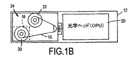
ここで図1Aおよび図1Bを参照すると、本開示のさまざまな実施形態に従った書込み後直接読出し(DRAW)機能を用いた光学データ記憶システムの動作または方法を例示するブロック図が示される。図1Aは側面図であり、図1Bは上面図または平面図である。図1Aおよび図1Bに示される代表的な実施形態においては、光学データ記憶システム10は、光学テープ16によって実現される光学データ記憶媒体14を収容する光学テープドライブ12によって実現される。光学テープドライブに関して図示および記載されているが、当業者であれば、本開示の教示が、たとえば光ディスクなどのさまざまなタイプの追記型または再書込み可能な光学媒体を用い得る他のさまざまなタイプの光学データ記憶装置にも適用され得ることを認識するだろう。一実施形態においては、光学テープ16は、テープの幅にわたって全体的に延在する複数のトラックを有する1/2インチ(12.7mm)幅のテープであり、この明細書中においてより詳細に例示および記載されるように、所望の記憶容量および性能特徴に応じて長さが異なっていてもよい。光学テープ16は、光学テープドライブ12に手作業でまたは自動的に搭載または装着される保護ケースまたはカートリッジ18内に含まれる関連するスプール30に巻きつけられてもよい。搬送機構24は、キャリッジを介して、光学テープ16を少なくとも1つの光ピックアップユニット(OPU)または光学ヘッド20を通過させ、典型的にはテープドライブ12内にある巻取りスプール22にまで移動させる。搬送機構24が少なくとも1つのコントローラおよび関連する電子機器26に応答してカートリッジ18と巻取りスプール22との間で光学テープ16を移動させると、OPU20は、光学テープ16に対するデータの書込みおよびデータの読出しを行う。以下により詳細に説明するように、テープがOPU20を通り過ぎてどちらかの方向、すなわち、カートリッジ18から巻取りスプール22への方向または巻取りスプール22からカートリッジ18への方向、に移動するとき、光学テープ16に対するデータの読出し/書込みが、蛇行した複数のトラックのうち1つ以上のトラックにおいて行われてもよい。
Referring now to FIGS. 1A and 1B, a block diagram illustrating an operation or method of an optical data storage system using a direct write after read (DRAW) function in accordance with various embodiments of the present disclosure is shown. 1A is a side view, and FIG. 1B is a top view or a plan view. In the exemplary embodiment shown in FIGS. 1A and 1B, the optical
光学ヘッド20は、全体的に参照番号30で表わされる、付随する光学系と関連する電気機械サーボ制御装置とを含み得る。これら光学系および電気機械サーボ制御装置は、図2を参照してより詳細に例示および記載されるように、データの書込み/読出しを行うために、より高出力の変調された書込みビームとより低出力の連続波(cw:continuous wave)の読出しビームとを対物レンズへと方向付け、この対物レンズが、記憶媒体上の対応するスポットにビームを収束させる。さまざまなサーボメカニズム(具体的には図示せず)は、光学テープ16上の複数のトラック36のうち選択された1つのトラックに対してビームを位置決め/位置合わせするために用いられてもよい。
The
図2は、本開示に従った書込み後直接読出しのためのシステムの動作または方法を示すブロック図である。図2の代表的な実施形態においては、第1のコヒーレント光ビーム40および第2のコヒーレント光ビーム44を有する光ピックアップユニット(OPU)20は、単一のヘッドまたはOPUだけを用いてDRAW機能を提供する。ビーム40および44は、たとえば、(図3に最も良く示される)レーザーダイオードなどの対応するコヒーレント光源によって生成されてもよい。代替的には、ビームを分割するために、単一または共通のコヒーレント光源が関連する光学系と共に用いられてもよい。しかしながら、この明細書中においてより詳細に記載されるように、読出しビームおよび書込みビームの両方を発生させるために単一の光源または共通の光源を使用した場合、データを読出したり、記憶媒体へのデータの書込みに付随する変調の作用をフィルタリングしたりするのに用いられる反射ビームをより緻密に処理することが必要となるかもしれない。
FIG. 2 is a block diagram illustrating a system operation or method for direct read-after-write according to the present disclosure. In the exemplary embodiment of FIG. 2, an optical pickup unit (OPU) 20 having a first
本開示に従ったさまざまな実施形態においては、OPU20は、第1のコヒーレント光ビーム40を発生させるための第1のレーザー320(図3)および第2のコヒーレント光ビーム44を発生させるための第2のレーザー322(図3)を含む。(図3において最も良く示される)関連する光学系は、第1のビームと第2のビームとを合成して、これらビームを、光学テープ16上の複数のトラック36のうち選択されたトラック「n」内における関連するスポット50および54にそれぞれ収束させる。光スポット50および54は、光学テープ16に対するデータの書込および取出しを行うために、OPU20のさまざまな光学素子および電気機械素子によって処理されてもよい。
In various embodiments in accordance with the present disclosure, the
ここで図2および図3を参照すると、第1の光源またはレーザー320および第2の光源またはレーザー322は、DRAW機能をもたらすために、さまざまな出力レベルかつさまざまなモードで動作し得る。たとえば、ビーム40およびスポット50を発生させる第1の光源320は、より高出力で動作させて、光学テープ16上に対応するデータインプレッション(data impression)60を書込むよう変調されてもよく、第2の光源322は、連続波(cw)モードでより低出力で動作させて、ビーム44およびスポット54を設けて、ビーム40によって書込んだ後に直接データインプレッション60を読出してもよい。第2の(DRAW)スポット54は、データインプレッション60を読出す前に安定させるのに十分な時間が与えられるように、書込みスポット50に対してテープ16の進行方向64の下流側において十分間隔を空けて位置決めされる。一実施形態においては、中心スポット50は、DRAWスポット54の平均出力よりも10倍から20倍高い平均出力を有していてもよい。たとえば、中心スポット50は、書込データに対して約8mWの平均出力を有していてもよく、DRAWスポット54は、書込み後に直接データを読出すために約0.35mWの平均出力を有しているだけでもよい。DRAWスポット54が低出力であることにより、それが、光学記憶媒体またはテープ16上に予め書込まれたデータを変更しない程度に十分に低いエネルギだけを含むことが確実にされるだろう。
Referring now to FIGS. 2 and 3, the first light source or
代表的な一実施形態においては、スポット50および54は、予めフォーマットされた光学テープ媒体16上のデータトラック36の軸と一致するよう、OPU製造プロセスにおいて機械的に位置合わせされる。加えて、中心スポット50とサテライト/サイドスポット54との間におけるテープ16の移動距離(d)により、光学テープ媒体16の最速の予想直線テープ速度および特徴に基づいて、光学テープ媒体16に書込まれたデータが安定するのに十分な時間が与えられるように、これらスポット50および54が大まかに位置決めされる。一実施形態においては、OPU20は、約10μm〜約20μmの距離(d)をもたらすように製造される。
In one exemplary embodiment, the
いくつかの従来の光学記憶装置は、1つのタイプのトラッキング動作に加えて、読出し、書込みおよび収束のために、より高出力の放射ビーム40からの中心スポット50を用いる。サテライトスポットは、特定のタイプの媒体のための別のタイプのトラッキングに用いられてもよい。これらの応用例においては、サテライトスポットは、光学テープ16の単一の選択されたトラック36に沿って、互いと、または中心スポット50と位置合わせされなくてもよい。典型的なサテライトビームの従来の機能とは対照的に、本開示に従ったさまざまな実施形態は、書込み後直接読出し(DRAW)機能を提供するためにサテライトスポット54を用いる。
Some conventional optical storage devices use a
先に説明したとおり、第1のレーザビーム40は、より高出力で動作して、光学テープ16の光学活性層の構造を変化させ、複数のトラック36のうち選択された1つのトラック36上にデータマーク60を書込むように変調される。サテライトDRAWビーム44は、光学テープ16に達したときにははるかに低出力になっており、このため、光学テープ16の光学活性層を変質させてしまうことがない。しかしながら、サテライトDRAWビーム44は、データマーク60を検出してDRAW機能をもたらすために、光学テープ16から反射した後に十分な出力を有するように設計されている。
As described above, the
図3は、本開示のさまざまな実施形態に従った光学データストレージのためのDRAWシステムの動作または方法を示すブロック図である。図示される代表的な実施形態においては、第1のコヒーレント光源320および第2のコヒーレント光源322を含む光学部品が単一の光学ヘッドまたはOPU内に含まれる。たとえば、コヒーレント光源320および322はダイオードレーザによって実現されてもよい。特定の実現例に応じて、装置10(図1)などの光学記憶装置は、光学テープ16の対応するトラック36に対するデータの書込み/読出しを同時に行うために複数の光学ヘッドを含んでもよい。OPU20は、コヒーレント光源320、322に加えて、振幅ビームスプリッタ330を含んでもよい。振幅ビームスプリッタ330は、発散ビーム324および326を合成して合成ビーム328にするよう動作する。合成ビーム328は、振幅ビームスプリッタ330の後段に位置決めされたコリメートレンズ332を通過する。合成光328はレンズ332によってコリメートされ、次いで、コリメートレンズ332に対して後段に位置決めされた偏光ビームスプリッタ340を通過する。1/4波長板342などの波リターダは、偏光ビームスプリッタ340の後段に位置決めされて、光学記憶媒体16に方向付けられた偏光328を光学記憶媒体16からの反射光348に対して相対的に変化させ、これにより、偏光ビームスプリッタ340によって反射光348をミラー350に向けなおすことを容易にする。次いで、スポット44からの反射光348は、ミラー350によって、DRAW収束レンズ352を介して、一実施形態におけるフォトダイオードアレイによって実現される光検出器360へと方向付けられる。
FIG. 3 is a block diagram illustrating the operation or method of a DRAW system for optical data storage according to various embodiments of the present disclosure. In the exemplary embodiment shown, optical components including a first coherent
1/4波長板342を通過する合成光328を対物レンズ346によって収束させて、光学テープ16上の選択されたトラック内においてスポット50および54を形成する。単一の対物レンズ346を用いて、レーザー源320からの光を第1のスポット50に収束させ、レーザー源322からの光を第2のスポット54に収束させつつ、部分的に重なるビーム経路または共通のビーム経路をもたらすために、さまざまなストラテジが用いられてもよい。たとえば、レーザー源320、322によって光のさまざまな波長を発生させてもよく、または、ビーム経路同士が直接重ならず、互いに対してわずかに異なる入射角を有していてもよい。
The combined light 328 passing through the quarter-
図3の代表的な実施形態に示されるように、光検出器360は、光学記憶媒体16から反射した光を対物レンズ346および偏向ビームスプリッタ340を介して受けるように構成されたDRAWレンズ352、ミラー350および1/4波長板342などの関連する光学系を含む。第1のレーザー320、第2のレーザー322および光検出器360と通信するコントローラ26(図1)は、第1のレーザー320からの光324を変調して、光学記憶媒体16の選択されたトラック36にデータを書込み、かつ、第2のレーザー322を連続波(cw)モードで動作させて、光学記憶媒体16の選択されたトラック36からデータを読出して、書込み後直接読出し機能を提供するための制御ロジックを含む。コントローラ26は、ビーム326を用いて読出されたデータをビーム324を用いて書込まれたデータと比較してデータ検証および記憶装置診断を行うために、さまざまなストラテジを用いてもよい。
As shown in the exemplary embodiment of FIG. 3, the
さまざまな実施形態においては、振幅ビームスプリッタ330は、第1のレーザー320からの入射光324のうち約90%以上をコリメートレンズ332を介して伝達し、残りの光(損失分は考慮されない)を光アブソーバまたはビームダンプ370に向かって反射させるように構成される。したがって、振幅ビームスプリッタ330はまた、第2のレーザー322からの入射光326のうち約90%をビームダンプ370へと伝達し、第2のレーザー322からの入射光326のうち約10%未満をコリメートレンズ332へと向けなおすこととなる。一実施形態においては、振幅ビームスプリッタ330は、光324のうち約95%を伝達し、残りの光5%を光アブソーバ370に向けなおす。同様に、光326のうち約95%はビームダンプ370に伝達され、残りの光5%がコリメートレンズ332に向けなおされる。図3に示されるように、任意のビームダンプ370は、第1のレーザー320からの光のうち振幅ビームスプリッタ330によって向けなおされる比較的わずかな部分と、第2のレーザー322からの光のうち振幅ビームスプリッタ330を介して伝達される比較的広範な部分とを吸収するように位置決めされるかまたは構成される。この実施形態においては、光学テープ16に対して(他のすべての構成要素に伴う光損失を無視して)8mWの平均書込出力を与えるために、書込みレーザー320は、約8.4mWで動作し、振幅ビームスプリッタ330を介して95%を伝達することとなるだろう。同様に、DRAWレーザー322は、7mWの比較的低出力で動作して、光学テープ16において0.35mWの平均読出出力を与え、5%だけを振幅ビームスプリッタ330によって光学テープ16へと向けなおすこととなるだろう。
In various embodiments, the
図4は、本開示のさまざまな実施形態に従った、DRAW機能を用いた光学データストレージのためのシステムの動作または方法を示すブロック図である。当業者であれば、書込み後直接読出し機能を提供するために、光学記憶媒体に書込まれたデータを、書込み後に直接読出されたデータと比較する関連するプログラム済みマイクロプロセッサを備えたさまざまな光学部品によって、図4に表わされる機能が実行され得ることを認識するだろう。1つ以上の光学部品によって単独で実行されようと、またはプログラム済みマイクロプロセッサベースのコントローラと組み合わせて実行されようと、図示されるさまざまなステップまたは機能は、示される順序で、並行して、または省略されたいくつかの場合において実行されてもよい。明示的に例示されていないが、当業者であれば、例示されるステップまたは機能のうちの1つ以上が特定の実現例に応じて繰返し実行され得ることを認識するだろう。同様に、代表的な実施形態において示される順序は、この明細書中に記載される特徴および利点を実現するために必ずしも必要とされるものではなく、例示および説明を容易にするために提供されるものである。 FIG. 4 is a block diagram illustrating a system operation or method for optical data storage using DRAW functionality, in accordance with various embodiments of the present disclosure. Those of ordinary skill in the art will be able to use a variety of optics with associated programmed microprocessors that compare data written to optical storage media with data read directly after writing to provide a direct read after write function. It will be appreciated that the function can be performed by the component as depicted in FIG. The various steps or functions illustrated, whether performed alone by one or more optical components, or in combination with a programmed microprocessor-based controller, are performed in the order shown, in parallel, or It may be executed in some cases omitted. Although not explicitly illustrated, those skilled in the art will recognize that one or more of the illustrated steps or functions may be performed iteratively depending on the particular implementation. Similarly, the order shown in the exemplary embodiments is not necessarily required to achieve the features and advantages described in this specification, but is provided for ease of illustration and description. Is.
スポットの収束や、選択されたトラックとの位置合わせなどのさまざまな制御機能は、たとえば、光学記憶装置内における関連する構成要素または装置を制御するために、図4の単純なフローチャートにおける1つ以上の機能によって表わされるロジックまたはコードを用いて、コントローラまたはプロセッサによって実行されてもよい。制御ロジックは、マイクロプロセッサベースのコントローラによって実行される命令を用いてソフトウェアにおいて実現されてもよい。当然ながら、制御ロジックは、特定の実現例に応じて、1つ以上のコントローラまたは同等の電子機器においてソフトウェア、ハードウェア、またはソフトウェアとハードウェアとの組み合わせで実現されてもよい。ソフトウェアで実現される場合、制御ロジックは、光学記憶装置における1つ以上の構成要素を制御するためにコンピュータによって実行されるコードまたは命令を表わすデータを記憶した1つ以上のコンピュータ読出し可能記憶媒体に記憶されてもよい。コンピュータ読出し可能記憶媒体は、実行可能な命令および関連するデータを保持するために電気的、磁気的、光学的、および/または混成型ストレージを利用するいくつかの公知の物理的デバイスのうちの1つ以上を含んでもよい。 Various control functions such as spot convergence and alignment with a selected track may be performed by one or more of the simple flow charts of FIG. 4, for example, to control related components or devices in an optical storage device. It may be executed by a controller or processor using logic or code represented by the functions of The control logic may be implemented in software using instructions executed by a microprocessor-based controller. Of course, the control logic may be implemented in software, hardware, or a combination of software and hardware in one or more controllers or equivalent electronic devices, depending on the particular implementation. When implemented in software, control logic resides in one or more computer-readable storage media that store data representing code or instructions executed by a computer to control one or more components in an optical storage device. It may be stored. A computer readable storage medium is one of several known physical devices that utilize electrical, magnetic, optical, and / or hybrid storage to hold executable instructions and associated data. More than one may be included.
DRAW機能を用いる光学ストレージのための代表的なシステムの動作または方法は、ブロック410によって表わされるように、光学記憶媒体へのデータの書込み中に、より高出力で変調される第1のレーザーからの光と、より低出力で連続波モードで動作させる第2のレーザーからの光とを合成するステップを含み得る。関連する光学系は、ブロック420によって表わされるように、第1のレーザーからの光を、光学記憶媒体上の選択されたトラック内における第1のスポットに収束させるために用いられてもよい。同様に、1つ以上の光学装置は、ブロック420によって表わされるように、第2のレーザーからの光を、第1のスポットに対して光学記憶媒体の進行方向の下流側にある、光学記憶媒体上の選択されたトラック内における第2のスポットへと収束させるのに用いられてもよい。先に例示および記載したように、第1のレーザーおよび第2のレーザーは、同じ/共通の光学部品/装置のうち1つ以上を用いて、ビームを光学記憶媒体へと方向付けて、当該ビームを、選択されたトラック内における対応するスポットに収束させてもよい。
An exemplary system operation or method for optical storage using the DRAW function is from a first laser that is modulated at a higher power during writing of data to an optical storage medium, as represented by
また図4に示されるように、本開示に従ったシステムまたは方法は、概してブロック440によって表わされるように、書込み後直接読出し機能を提供するために、第2のスポットから反射した光をOPUの内の光検出器に方向付けるステップを含み得る。特定の実現例に応じて、本開示に従ったシステムまたは方法はまた、ブロック435によって表わされるように、光学記憶媒体から反射した光を光検出器に向けなおすことを容易にするために、光学記憶媒体に方向付けられた偏光を光学記憶媒体から反射した光に対して相対的に変化させるステップを含み得る。図3に関連付けて上述したように、これは、1/4波長板または同様の波リターダを、たとえば偏光ビームスプリッタと併用して実現されてもよい。
As also shown in FIG. 4, a system or method according to the present disclosure generally reflects light reflected from the second spot of the OPU to provide a direct read function after writing, as represented by
さまざまな実施形態は、任意には、ブロック450によって表わされるように、光学記憶媒体に方向付けられていない第1および第2のレーザーからの光を、光アブソーバまたはビームダンプに方向付けるように位置決めされるかまたは構成される1つ以上の装置を含んでもよい。
Various embodiments optionally position light to direct light from the first and second lasers not directed to the optical storage medium to the optical absorber or beam dump, as represented by
ブロック440によって表わされるように第2のスポットから光検出器に反射し返された光は、ブロック460によって表わされるように、読出しデータを書込みデータと比較して書込データ検証を行うために用いられてもよい。当業者に認識され得るように、読出しデータは、書込みデータに対して光学媒体伝送遅延分だけ時間がずらされるだろう。ビーム経路差および/または処理遅延のための補償が、特定の実現例に応じて提供されてもよい。
The light reflected back from the second spot to the photodetector as represented by
そのため、本開示に従ったさまざまな実施形態は、単一のOPUまたは光学ヘッドを用いて、光学データ記憶装置のための書込み後直接読出し(DRAW)機能のためのシステムおよび方法を提供し、これにより、複雑さを減らし、関連するコストを削減する。 As such, various embodiments in accordance with the present disclosure provide systems and methods for a direct write after read (DRAW) function for optical data storage using a single OPU or optical head. Reduces complexity and associated costs.
具体的な実施形態を上述してきたが、これらの実施形態が添付の特許請求の範囲に包含される実現可能なあらゆる形態を記載することは意図されていない。明細書において用いられる語は、限定ではなく説明のためのものであって、開示および請求項の精神および範囲から逸脱することなくさまざまな変更がなされ得ることが理解される。先に記載したように、さまざまな実施形態の特徴は、明示的に記載または例示されない可能性のあるさらに他の実施形態を形成するように組合わされてもよい。さまざまな実施形態が利点を提供するものとして、または、1つ以上の所望の特徴に関して他の実施形態または先行技術の実現例よりも好ましいものとして記載されていたかもしれないが、当業者であれば、具体的な応用例および実現例に応じた所望の全体的なシステム属性を達成するために、1つ以上の機能または特徴が損なわれる可能性があることを認識する。これらの属性は、コスト、強度、耐久性、ライフ・サイクル・コスト、市場性、外観、パッケージング、サイズ、保守容易性、重量、製造し易さ、組立の容易さなどを含むが、これらに限定されない。このため、1つ以上の特徴に関して他の実施形態または先行技術の実現例ほど望ましいものではないと記載された実施形態は開示の範囲外とはならず、特定の応用例にとって望ましいものとなる可能性がある。 Although specific embodiments have been described above, it is not intended that these embodiments be described in all possible forms that are encompassed by the appended claims. It is understood that the terminology used in the specification is for purposes of illustration and not limitation, and that various modifications can be made without departing from the spirit and scope of the disclosure and the claims. As described above, the features of the various embodiments may be combined to form yet other embodiments that may not be explicitly described or illustrated. Although various embodiments may have been described as providing advantages or preferred over other embodiments or prior art implementations in terms of one or more desired features, those skilled in the art For example, it will be appreciated that one or more functions or features may be compromised in order to achieve the desired overall system attributes depending on the specific application and implementation. These attributes include cost, strength, durability, life cycle cost, marketability, appearance, packaging, size, serviceability, weight, ease of manufacture, ease of assembly, etc. It is not limited. Thus, embodiments described as less desirable than other embodiments or prior art implementations with respect to one or more features may not be outside the scope of the disclosure and may be desirable for a particular application. There is sex.
Claims (13)
光ピックアップユニットと、
前記光ピックアップユニット内に配置された第1のレーザーと、
前記光ピックアップユニット内に配置された第2のレーザーと、
前記光ピックアップユニット内に配置され、前記第1のレーザーからの光と前記第2のレーザーからの光とを合成して、当該合成された光を光学記憶媒体へと方向付けるように位置決めされた振幅ビームスプリッタと、
前記合成された光をコリメートするように前記振幅ビームスプリッタの後段に位置決めされたコリメートレンズと、
前記コリメートレンズの後段に位置決めされた偏光ビームスプリッタと、
前記偏光ビームスプリッタの後段に位置決めされた1/4波長板と、
前記1/4波長板の後段に位置決めされ、前記第1のレーザーからの光を前記光学記憶媒体の選択されたトラック上の第1のスポットに収束させ、前記第2のレーザーからの光を、前記第1のスポットの下流側にある前記選択されたトラック上の第2のスポットに収束させるように構成された対物レンズと、
前記光学記憶媒体から反射した光を前記対物レンズおよび前記偏光ビームスプリッタを介して受けるように構成された光検出器および関連する光学系と、
前記第1のレーザーおよび前記第2のレーザーならびに前記光検出器と通信して、前記第1のレーザーからの光を変調して前記光学記憶媒体の選択されたトラックにデータを書込むとともに、前記第2のレーザーを用いて前記光学記憶媒体の選択されたトラックからデータを読出すことで、書込み後直接読出し機能を提供するコントローラとを備え、
前記振幅ビームスプリッタは、前記第1のレーザーからの入射光のうち約90%以上を前記コリメートレンズに伝達し、前記第2のレーザーからの入射光のうち約10%未満を前記コリメートレンズに向けなおすように構成される、光学記憶システム。 An optical storage system,
An optical pickup unit;
A first laser disposed in the optical pickup unit;
A second laser disposed in the optical pickup unit;
Positioned within the optical pickup unit and positioned to synthesize the light from the first laser and the light from the second laser and direct the synthesized light to an optical storage medium An amplitude beam splitter;
A collimating lens positioned downstream of the amplitude beam splitter to collimate the combined light;
A polarizing beam splitter positioned downstream of the collimating lens;
A quarter-wave plate positioned downstream of the polarizing beam splitter;
Positioned downstream of the quarter-wave plate, the light from the first laser is focused to a first spot on a selected track of the optical storage medium, and the light from the second laser is An objective lens configured to converge to a second spot on the selected track downstream of the first spot;
A photodetector and associated optics configured to receive light reflected from the optical storage medium via the objective lens and the polarizing beam splitter;
Communicating with the first laser and the second laser and the photodetector to modulate light from the first laser to write data to selected tracks of the optical storage medium; and A controller for providing a direct read function after writing by reading data from a selected track of the optical storage medium using a second laser ;
The amplitude beam splitter transmits about 90% or more of incident light from the first laser to the collimating lens and directs less than about 10% of incident light from the second laser to the collimating lens. An optical storage system configured to correct .
前記光学記憶媒体から反射した光を、前記偏光ビームスプリッタから前記光検出器に向けなおすように位置決めされたミラーと、
前記ミラーから反射した光を前記光検出器上に収束させるように位置決めされたレンズとを備える、請求項1に記載の光学記憶システム。 The related optical system is:
A mirror positioned to redirect light reflected from the optical storage medium from the polarizing beam splitter to the photodetector;
The optical storage system of claim 1, comprising: a lens positioned to focus light reflected from the mirror onto the photodetector.
光学ヘッドを備え、
前記光学ヘッドは、前記光学記憶媒体へのデータの書込み中に、より高出力で変調される第1のコヒーレント光源と、前記第1のコヒーレント光源がデータを書込んでいる間、より低出力で連続波モードで動作する第2のコヒーレント光源と、前記第1のコヒーレント光源からの光と前記第2のコヒーレント光源からの光とを合成する光学系とを有し、
前記光学系は、前記第1のコヒーレント光源からの光を、前記光学記憶媒体上の選択されたトラックの第1のスポットに収束させ、前記第2のコヒーレント光源からの光を、前記光学記憶媒体の移動方向に対して前記第1のスポットから下流側にある前記選択されたトラック上の第2のスポットに収束させ、前記光学記憶媒体からの反射光を光検出器に方向付け、
前記光学記憶システムは、前記光学ヘッドに結合されたコントローラをさらに備え、
前記コントローラは、前記光検出器によって検出された前記第2のコヒーレント光源からの反射光を用いて、前記選択されたトラックからの書込み後に直接にデータを読出しつつ、前記第1のコヒーレント光源を用いて、前記選択されたトラックに沿ってデータを書込むために、前記光学ヘッドを選択的に位置決めし、
前記光学系は、
前記合成された光を前記光学記憶媒体へと方向付けるように位置決めされた振幅ビームスプリッタと、
前記合成された光をコリメートするように前記振幅ビームスプリッタの後段に位置決めされたコリメートレンズとをさらに有し、
前記振幅ビームスプリッタは、前記第1のコヒーレント光源からの入射光のうち約90%以上を伝達し、前記第2のコヒーレント光源からの光のうち約10%未満を前記光学記憶媒体へと向けなおす、光学記憶システム。 An optical storage system containing an optical storage medium having a plurality of tracks for storing data,
With an optical head,
The optical head includes a first coherent light source that is modulated at a higher output during the writing of data to the optical storage medium, and a lower output while the first coherent light source is writing data. A second coherent light source that operates in a continuous wave mode; and an optical system that combines light from the first coherent light source and light from the second coherent light source;
The optical system converges light from the first coherent light source to a first spot of a selected track on the optical storage medium and causes light from the second coherent light source to converge on the optical storage medium. Focusing on a second spot on the selected track downstream from the first spot with respect to the direction of movement of the light, directing reflected light from the optical storage medium to a photodetector,
The optical storage system further comprises a controller coupled to the optical head,
The controller uses the first coherent light source while reading data directly after writing from the selected track using reflected light from the second coherent light source detected by the photodetector. Selectively positioning the optical head to write data along the selected track;
The optical system is
An amplitude beam splitter positioned to direct the combined light to the optical storage medium;
Further have a said amplitude beam collimating lens positioned downstream of the splitter to collimate the combined light,
The amplitude beam splitter transmits about 90% or more of incident light from the first coherent light source and redirects less than about 10% of light from the second coherent light source to the optical storage medium. , Optical storage system.
入射した光の偏光を変化させるデバイスを含み、前記デバイスは、前記偏光ビームスプリッタと前記光学記憶媒体との間に位置決めされ、
前記偏光を変化させるためのデバイスと前記光学記憶媒体との間に配置された対物レンズを含み、
前記デバイスは1/4波長板を含む、請求項8に記載の光学記憶システム。 The optical system further includes
Including a device that changes the polarization of incident light, the device positioned between the polarizing beam splitter and the optical storage medium;
An objective lens disposed between the device for changing the polarization and the optical storage medium,
The optical storage system of claim 8 , wherein the device comprises a quarter wave plate.
振幅ビームスプリッタが、前記光学記憶媒体へのデータ書込み中に、より高出力で変調される第1のレーザーからの光と、より低出力で連続波モードで動作する第2のレーザーからの光とを合成するステップと、
コリメートレンズが、前記合成された光をコリメートするステップと、
前記第1のレーザーからの光を前記光学記憶媒体上の選択されたトラック内における第1のスポットに収束させるステップと、
前記第2のレーザーからの光を、前記光学記憶媒体の進行方向において前記第1のスポットに対して下流側にある、前記光学記憶媒体上の選択されたトラック内における第2のスポットに収束させるステップと、
前記第2のスポットから反射した光を光検出器に方向付けることで、書込み後直接読出し機能を提供するステップと、
前記第1のレーザーからの入射光のうち約90%以上を前記コリメートレンズに伝達し、前記第2のレーザーからの入射光のうち約10%未満を前記コリメートレンズに向けなおすステップとを含み、
前記振幅ビームスプリッタは、前記合成された光を前記光学記憶媒体へと方向付けるように位置決めされ、
前記コリメートレンズは、前記振幅ビームスプリッタの後段に位置決めされる、方法。 A method for providing a post-write direct read function for an optical storage device that reads and writes data to and from an optical storage medium,
An amplitude beam splitter, during writing of data to the optical storage medium, light from a first laser that is modulated at a higher output and light from a second laser that operates in a continuous wave mode at a lower output A step of synthesizing
A collimating lens collimating the synthesized light;
Focusing the light from the first laser to a first spot in a selected track on the optical storage medium;
Focus the light from the second laser to a second spot in a selected track on the optical storage medium that is downstream from the first spot in the direction of travel of the optical storage medium Steps,
Providing a direct read function after writing by directing light reflected from the second spot to a photodetector ;
Transmitting about 90% or more of the incident light from the first laser to the collimating lens, and redirecting less than about 10% of the incident light from the second laser to the collimating lens ;
The amplitude beam splitter is positioned to direct the combined light to the optical storage medium;
The method wherein the collimating lens is positioned downstream of the amplitude beam splitter.
Applications Claiming Priority (3)
| Application Number | Priority Date | Filing Date | Title |
|---|---|---|---|
| US13/416,633 | 2012-03-09 | ||
| US13/416,633 US8792317B2 (en) | 2012-03-09 | 2012-03-09 | Optical storage device with direct read after write |
| PCT/US2013/025498 WO2013133930A1 (en) | 2012-03-09 | 2013-02-11 | Optical storage device with direct read after write |
Publications (3)
| Publication Number | Publication Date |
|---|---|
| JP2015513167A JP2015513167A (en) | 2015-04-30 |
| JP2015513167A5 JP2015513167A5 (en) | 2016-03-24 |
| JP6289384B2 true JP6289384B2 (en) | 2018-03-07 |
Family
ID=47755009
Family Applications (1)
| Application Number | Title | Priority Date | Filing Date |
|---|---|---|---|
| JP2014560920A Active JP6289384B2 (en) | 2012-03-09 | 2013-02-11 | Optical storage device using direct reading after writing |
Country Status (7)
| Country | Link |
|---|---|
| US (1) | US8792317B2 (en) |
| EP (1) | EP2823483A1 (en) |
| JP (1) | JP6289384B2 (en) |
| CN (1) | CN104160446A (en) |
| AU (1) | AU2013230807B2 (en) |
| HK (1) | HK1203101A1 (en) |
| WO (1) | WO2013133930A1 (en) |
Families Citing this family (6)
| Publication number | Priority date | Publication date | Assignee | Title |
|---|---|---|---|---|
| US8869179B2 (en) | 2011-06-17 | 2014-10-21 | Oracle International Corporation | Rotary head data storage and retrieval system and method |
| US9324347B2 (en) * | 2012-09-19 | 2016-04-26 | Oracle International Corporation | Apparatus and method for controlling tape movement in a rotary head data storage system and retrieval system |
| US8897113B2 (en) | 2012-11-07 | 2014-11-25 | Oracle International Corporation | Rotary head data storage and retrieval system and method for data verification |
| US8780682B2 (en) | 2012-11-07 | 2014-07-15 | Oracle International Corporation | Rotary head data storage and retrieval system and method for data erasure |
| US8793713B2 (en) | 2012-11-07 | 2014-07-29 | Oracle International Corporation | Rotary head data storage and retrieval system and method with tape medium having transverse primary data tracks and longitudinal secondary data track |
| US9245572B2 (en) | 2012-11-21 | 2016-01-26 | Oracle International Corporation | Optical tape pick up unit with holographic optical element |
Family Cites Families (21)
| Publication number | Priority date | Publication date | Assignee | Title |
|---|---|---|---|---|
| JPH068934B2 (en) * | 1982-01-11 | 1994-02-02 | オリンパス光学工業株式会社 | Luminous flux combiner |
| US4888759A (en) * | 1982-09-09 | 1989-12-19 | Burroughs Corporation | Laser optical memory system having beam combining and separating apparatus for combining and separating reading and writing laser beams |
| JPH0816987B2 (en) * | 1982-10-15 | 1996-02-21 | 松下電器産業株式会社 | Optical recording / reproducing device |
| US4694447A (en) * | 1984-07-12 | 1987-09-15 | International Business Machines Corp. | Optical signal recorders employing two lasers and methods therefor |
| JP3014553B2 (en) * | 1991-10-21 | 2000-02-28 | 三星電子株式会社 | Recording and / or reproducing apparatus for optical recording tape |
| JPH0660417A (en) * | 1992-08-10 | 1994-03-04 | Olympus Optical Co Ltd | Optical head |
| JP2768418B2 (en) * | 1992-09-02 | 1998-06-25 | キヤノン株式会社 | Optical information recording / reproducing device |
| US5444233A (en) * | 1992-09-02 | 1995-08-22 | Canon Kabushiki Kaisha | Optical or magnetooptical information recording/reproducing apparatus and a focusing pull-in method for such apparatus generating a light beam for focusing error signal detection |
| JPH10162365A (en) | 1996-12-03 | 1998-06-19 | Olympus Optical Co Ltd | Optical information recording and reproducing device |
| US6141312A (en) | 1997-09-30 | 2000-10-31 | Compaq Computer Coporation | Optical tape drive that performs direct read after write operations |
| US6343058B1 (en) * | 1997-10-30 | 2002-01-29 | Ricoh Company, Ltd. | Optical pickup device applicable to two kinds of recording media with minimized deterioration of a beam spot |
| US6314071B1 (en) * | 1998-02-20 | 2001-11-06 | Zen Research (Ireland), Ltd. | Method and apparatus for reading multiple tracks and writing at least one track of an optical disk |
| CN1172299C (en) * | 1999-10-30 | 2004-10-20 | 三星电子株式会社 | Optical probe |
| US6442126B1 (en) | 2000-01-03 | 2002-08-27 | Eastman Kodak Company | Apparatus for recording and simultaneously reading information recorded on a moveable optical recording medium using objective lens and beam splitter |
| US6744719B2 (en) * | 2001-03-09 | 2004-06-01 | Imation Corp. | Method and apparatus for optical tracking in an edge-guided tape recorder |
| WO2003019545A1 (en) * | 2001-08-27 | 2003-03-06 | Koninklijke Philips Electronics N.V. | Optical scanning device |
| JPWO2005101393A1 (en) * | 2004-04-13 | 2008-03-06 | コニカミノルタオプト株式会社 | Objective optical system for optical pickup device, optical pickup device, drive device for optical information recording medium, condensing lens, and optical path synthesis element |
| CN100468538C (en) * | 2004-12-16 | 2009-03-11 | 鸿富锦精密工业(深圳)有限公司 | Light source and optical recording/recurrence device using the same |
| CN101432809A (en) | 2005-09-22 | 2009-05-13 | 皇家飞利浦电子股份有限公司 | Cross-talk cancellation in three-spots push-pull tracking error signal in optical disc systems |
| JP2009129502A (en) * | 2007-11-22 | 2009-06-11 | Sony Corp | Optical pickup and optical disk drive |
| US8614935B2 (en) | 2009-12-16 | 2013-12-24 | Oracle America, Inc. | Data storage system and method for calibrating same |
-
2012
- 2012-03-09 US US13/416,633 patent/US8792317B2/en active Active
-
2013
- 2013-02-11 WO PCT/US2013/025498 patent/WO2013133930A1/en active Application Filing
- 2013-02-11 JP JP2014560920A patent/JP6289384B2/en active Active
- 2013-02-11 AU AU2013230807A patent/AU2013230807B2/en active Active
- 2013-02-11 EP EP13706833.4A patent/EP2823483A1/en not_active Ceased
- 2013-02-11 CN CN201380013076.1A patent/CN104160446A/en active Pending
-
2015
- 2015-04-13 HK HK15103569.8A patent/HK1203101A1/en unknown
Also Published As
| Publication number | Publication date |
|---|---|
| JP2015513167A (en) | 2015-04-30 |
| US20130235708A1 (en) | 2013-09-12 |
| EP2823483A1 (en) | 2015-01-14 |
| WO2013133930A1 (en) | 2013-09-12 |
| AU2013230807A1 (en) | 2014-09-11 |
| US8792317B2 (en) | 2014-07-29 |
| CN104160446A (en) | 2014-11-19 |
| HK1203101A1 (en) | 2015-10-16 |
| AU2013230807B2 (en) | 2018-07-05 |
Similar Documents
| Publication | Publication Date | Title |
|---|---|---|
| JP6289384B2 (en) | Optical storage device using direct reading after writing | |
| US7613100B2 (en) | Optical pickup device and focus control method therefor | |
| JP2015513167A5 (en) | ||
| JPH06309725A (en) | Two beam optical head | |
| JP3979562B2 (en) | Optical pickup device | |
| US7301879B1 (en) | Optical print head | |
| US8520485B2 (en) | Recording apparatus and servo control method | |
| US6373809B1 (en) | Multi-channel optical head for optical recording and reading optical storage data | |
| JP4771340B2 (en) | Optical pickup device and information equipment | |
| JP2005235276A (en) | Optical head, optical reproducing apparatus, and optical recording/reproducing apparatus | |
| JP4357557B2 (en) | Optical head and optical disk apparatus | |
| JP5957737B2 (en) | Optical pickup and optical recording / reproducing apparatus | |
| US20060245316A1 (en) | Optical head and information recording/reproducing apparatus | |
| US6381209B1 (en) | Multi-channel optical head for optical recording and reading optical storage data | |
| JP2003132581A (en) | Optical pickup and optical disc drive | |
| JP4797650B2 (en) | Optical pickup device | |
| US8488426B2 (en) | Disc device | |
| JP2005100480A (en) | Two-wavelength laser module | |
| JP2006236529A (en) | Optical disk recording/playback apparatus | |
| JP2007115365A (en) | Device for detecting optical output of optical pickup | |
| JP2001222839A (en) | Optical pickup device | |
| JP2006286079A (en) | Optical head and optical disk device | |
| JPH03119528A (en) | Optical pickup device and optical information recording and reproducing device using the same | |
| JPH01302536A (en) | Information recorder | |
| JPH05166222A (en) | Separation type optical pickup device |
Legal Events
| Date | Code | Title | Description |
|---|---|---|---|
| A521 | Request for written amendment filed |
Free format text: JAPANESE INTERMEDIATE CODE: A523 Effective date: 20160202 |
|
| A621 | Written request for application examination |
Free format text: JAPANESE INTERMEDIATE CODE: A621 Effective date: 20160202 |
|
| A977 | Report on retrieval |
Free format text: JAPANESE INTERMEDIATE CODE: A971007 Effective date: 20160823 |
|
| A131 | Notification of reasons for refusal |
Free format text: JAPANESE INTERMEDIATE CODE: A131 Effective date: 20160906 |
|
| A521 | Request for written amendment filed |
Free format text: JAPANESE INTERMEDIATE CODE: A523 Effective date: 20161102 |
|
| A131 | Notification of reasons for refusal |
Free format text: JAPANESE INTERMEDIATE CODE: A131 Effective date: 20170328 |
|
| A601 | Written request for extension of time |
Free format text: JAPANESE INTERMEDIATE CODE: A601 Effective date: 20170627 |
|
| A521 | Request for written amendment filed |
Free format text: JAPANESE INTERMEDIATE CODE: A523 Effective date: 20170718 |
|
| TRDD | Decision of grant or rejection written | ||
| A01 | Written decision to grant a patent or to grant a registration (utility model) |
Free format text: JAPANESE INTERMEDIATE CODE: A01 Effective date: 20180116 |
|
| A61 | First payment of annual fees (during grant procedure) |
Free format text: JAPANESE INTERMEDIATE CODE: A61 Effective date: 20180206 |
|
| R150 | Certificate of patent or registration of utility model |
Ref document number: 6289384 Country of ref document: JP Free format text: JAPANESE INTERMEDIATE CODE: R150 |
|
| R250 | Receipt of annual fees |
Free format text: JAPANESE INTERMEDIATE CODE: R250 |
|
| R250 | Receipt of annual fees |
Free format text: JAPANESE INTERMEDIATE CODE: R250 |
|
| R250 | Receipt of annual fees |
Free format text: JAPANESE INTERMEDIATE CODE: R250 |
|
| R250 | Receipt of annual fees |
Free format text: JAPANESE INTERMEDIATE CODE: R250 |