JP6288971B2 - Method for electronic control of bicycle gearshift device and electronic servo-assisted bicycle gearshift device - Google Patents
Method for electronic control of bicycle gearshift device and electronic servo-assisted bicycle gearshift device Download PDFInfo
- Publication number
- JP6288971B2 JP6288971B2 JP2013151673A JP2013151673A JP6288971B2 JP 6288971 B2 JP6288971 B2 JP 6288971B2 JP 2013151673 A JP2013151673 A JP 2013151673A JP 2013151673 A JP2013151673 A JP 2013151673A JP 6288971 B2 JP6288971 B2 JP 6288971B2
- Authority
- JP
- Japan
- Prior art keywords
- derailleur
- gear shift
- gear
- block
- desired position
- Prior art date
- Legal status (The legal status is an assumption and is not a legal conclusion. Google has not performed a legal analysis and makes no representation as to the accuracy of the status listed.)
- Active
Links
- 238000000034 method Methods 0.000 title claims description 40
- 101100129496 Arabidopsis thaliana CYP711A1 gene Proteins 0.000 claims description 37
- 101100083446 Danio rerio plekhh1 gene Proteins 0.000 claims description 37
- 101100129499 Arabidopsis thaliana MAX2 gene Proteins 0.000 claims description 32
- 230000033001 locomotion Effects 0.000 claims description 23
- 230000005540 biological transmission Effects 0.000 claims description 13
- 230000000737 periodic effect Effects 0.000 claims description 2
- 238000005259 measurement Methods 0.000 description 20
- 230000015654 memory Effects 0.000 description 17
- 230000007246 mechanism Effects 0.000 description 11
- 230000003247 decreasing effect Effects 0.000 description 10
- 230000008569 process Effects 0.000 description 7
- 238000010586 diagram Methods 0.000 description 6
- 239000000758 substrate Substances 0.000 description 6
- 230000008859 change Effects 0.000 description 4
- 230000007423 decrease Effects 0.000 description 4
- 238000006073 displacement reaction Methods 0.000 description 4
- 230000006870 function Effects 0.000 description 4
- 230000014509 gene expression Effects 0.000 description 3
- 230000001133 acceleration Effects 0.000 description 2
- 230000005284 excitation Effects 0.000 description 2
- 230000004048 modification Effects 0.000 description 2
- 238000012986 modification Methods 0.000 description 2
- 230000004913 activation Effects 0.000 description 1
- 239000003638 chemical reducing agent Substances 0.000 description 1
- 238000012937 correction Methods 0.000 description 1
- 238000012544 monitoring process Methods 0.000 description 1
- 238000010248 power generation Methods 0.000 description 1
Images


Classifications
-
- B—PERFORMING OPERATIONS; TRANSPORTING
- B62—LAND VEHICLES FOR TRAVELLING OTHERWISE THAN ON RAILS
- B62M—RIDER PROPULSION OF WHEELED VEHICLES OR SLEDGES; POWERED PROPULSION OF SLEDGES OR SINGLE-TRACK CYCLES; TRANSMISSIONS SPECIALLY ADAPTED FOR SUCH VEHICLES
- B62M25/00—Actuators for gearing speed-change mechanisms specially adapted for cycles
- B62M25/08—Actuators for gearing speed-change mechanisms specially adapted for cycles with electrical or fluid transmitting systems
-
- F—MECHANICAL ENGINEERING; LIGHTING; HEATING; WEAPONS; BLASTING
- F16—ENGINEERING ELEMENTS AND UNITS; GENERAL MEASURES FOR PRODUCING AND MAINTAINING EFFECTIVE FUNCTIONING OF MACHINES OR INSTALLATIONS; THERMAL INSULATION IN GENERAL
- F16H—GEARING
- F16H61/00—Control functions within control units of change-speed- or reversing-gearings for conveying rotary motion ; Control of exclusively fluid gearing, friction gearing, gearings with endless flexible members or other particular types of gearing
- F16H61/02—Control functions within control units of change-speed- or reversing-gearings for conveying rotary motion ; Control of exclusively fluid gearing, friction gearing, gearings with endless flexible members or other particular types of gearing characterised by the signals used
- F16H61/0202—Control functions within control units of change-speed- or reversing-gearings for conveying rotary motion ; Control of exclusively fluid gearing, friction gearing, gearings with endless flexible members or other particular types of gearing characterised by the signals used the signals being electric
- F16H61/0204—Control functions within control units of change-speed- or reversing-gearings for conveying rotary motion ; Control of exclusively fluid gearing, friction gearing, gearings with endless flexible members or other particular types of gearing characterised by the signals used the signals being electric for gearshift control, e.g. control functions for performing shifting or generation of shift signal
- F16H61/0213—Control functions within control units of change-speed- or reversing-gearings for conveying rotary motion ; Control of exclusively fluid gearing, friction gearing, gearings with endless flexible members or other particular types of gearing characterised by the signals used the signals being electric for gearshift control, e.g. control functions for performing shifting or generation of shift signal characterised by the method for generating shift signals
-
- F—MECHANICAL ENGINEERING; LIGHTING; HEATING; WEAPONS; BLASTING
- F16—ENGINEERING ELEMENTS AND UNITS; GENERAL MEASURES FOR PRODUCING AND MAINTAINING EFFECTIVE FUNCTIONING OF MACHINES OR INSTALLATIONS; THERMAL INSULATION IN GENERAL
- F16H—GEARING
- F16H9/00—Gearings for conveying rotary motion with variable gear ratio, or for reversing rotary motion, by endless flexible members
- F16H9/02—Gearings for conveying rotary motion with variable gear ratio, or for reversing rotary motion, by endless flexible members without members having orbital motion
- F16H9/04—Gearings for conveying rotary motion with variable gear ratio, or for reversing rotary motion, by endless flexible members without members having orbital motion using belts, V-belts, or ropes
-
- B—PERFORMING OPERATIONS; TRANSPORTING
- B62—LAND VEHICLES FOR TRAVELLING OTHERWISE THAN ON RAILS
- B62M—RIDER PROPULSION OF WHEELED VEHICLES OR SLEDGES; POWERED PROPULSION OF SLEDGES OR SINGLE-TRACK CYCLES; TRANSMISSIONS SPECIALLY ADAPTED FOR SUCH VEHICLES
- B62M9/00—Transmissions characterised by use of an endless chain, belt, or the like
- B62M9/04—Transmissions characterised by use of an endless chain, belt, or the like of changeable ratio
- B62M9/06—Transmissions characterised by use of an endless chain, belt, or the like of changeable ratio using a single chain, belt, or the like
- B62M9/10—Transmissions characterised by use of an endless chain, belt, or the like of changeable ratio using a single chain, belt, or the like involving different-sized wheels, e.g. rear sprocket chain wheels selectively engaged by the chain, belt, or the like
- B62M9/12—Transmissions characterised by use of an endless chain, belt, or the like of changeable ratio using a single chain, belt, or the like involving different-sized wheels, e.g. rear sprocket chain wheels selectively engaged by the chain, belt, or the like the chain, belt, or the like being laterally shiftable, e.g. using a rear derailleur
- B62M9/121—Rear derailleurs
- B62M9/122—Rear derailleurs electrically or fluid actuated; Controls thereof
-
- B—PERFORMING OPERATIONS; TRANSPORTING
- B62—LAND VEHICLES FOR TRAVELLING OTHERWISE THAN ON RAILS
- B62M—RIDER PROPULSION OF WHEELED VEHICLES OR SLEDGES; POWERED PROPULSION OF SLEDGES OR SINGLE-TRACK CYCLES; TRANSMISSIONS SPECIALLY ADAPTED FOR SUCH VEHICLES
- B62M9/00—Transmissions characterised by use of an endless chain, belt, or the like
- B62M9/04—Transmissions characterised by use of an endless chain, belt, or the like of changeable ratio
- B62M9/06—Transmissions characterised by use of an endless chain, belt, or the like of changeable ratio using a single chain, belt, or the like
- B62M9/10—Transmissions characterised by use of an endless chain, belt, or the like of changeable ratio using a single chain, belt, or the like involving different-sized wheels, e.g. rear sprocket chain wheels selectively engaged by the chain, belt, or the like
- B62M9/12—Transmissions characterised by use of an endless chain, belt, or the like of changeable ratio using a single chain, belt, or the like involving different-sized wheels, e.g. rear sprocket chain wheels selectively engaged by the chain, belt, or the like the chain, belt, or the like being laterally shiftable, e.g. using a rear derailleur
- B62M9/131—Front derailleurs
- B62M9/132—Front derailleurs electrically or fluid actuated; Controls thereof
Landscapes
- Engineering & Computer Science (AREA)
- General Engineering & Computer Science (AREA)
- Mechanical Engineering (AREA)
- Chemical & Material Sciences (AREA)
- Combustion & Propulsion (AREA)
- Transportation (AREA)
- Electric Propulsion And Braking For Vehicles (AREA)
- Gear-Shifting Mechanisms (AREA)
- Control Of Transmission Device (AREA)
- Traffic Control Systems (AREA)
Description
本発明は、自転車のギアシフト装置を電子制御する方法および電子サーボ支援型の自転車のギアシフト装置に関する。 The present invention relates to a method for electronically controlling a bicycle gear shift device and an electronic servo assisted bicycle gear shift device.
自転車の伝動システムは、ペダルクランク軸に結合した歯車と後輪ハブに結合した歯車との間に延びるチェーンを含む。ペダルクランク軸および後輪ハブの少なくとも一方が複数の歯車を有し、伝動システムには、ギアシフト装置が設けられる場合、前側のディレイラおよび/または後側のディレイラが設けられる。電子サーボ支援型のギアシフト装置の場合、各ディレイラは、チェーンを歯車間で移動させることによってギア比を変える可動のチェーン案内要素(ケージともいう)と、チェーン案内要素を移動させる電気機械式のアクチュエータとを有する。典型的に、このアクチュエータは、関節型の平行四辺形リンク機構、ラック機構、ウォームねじ機構などのリンク機構を介してチェーン案内要素に接続されたモータ(典型的には、電気モータ)と、ロータまたはロータからチェーン案内要素に至るまでの下流領域に位置する可動部品について位置および/または速度および/または加速度を検出するセンサとを有する。なお、一般に使用されている用語は、本明細書で使用する用語と少し異なる場合がある。 The bicycle transmission system includes a chain extending between a gear coupled to the pedal crankshaft and a gear coupled to the rear wheel hub. When at least one of the pedal crankshaft and the rear wheel hub has a plurality of gears, and the transmission system is provided with a gear shift device, a front derailleur and / or a rear derailleur is provided. In the case of an electronic servo-assisted gear shift device, each derailleur includes a movable chain guide element (also called a cage) that changes the gear ratio by moving the chain between gears, and an electromechanical actuator that moves the chain guide element. And have. Typically, the actuator includes a motor (typically an electric motor) connected to a chain guide element via a link mechanism such as an articulated parallelogram link mechanism, a rack mechanism, and a worm screw mechanism, and a rotor. Or a sensor for detecting position and / or speed and / or acceleration of a movable part located in a downstream region from the rotor to the chain guide element. Note that commonly used terms may differ slightly from terms used in this specification.
ギア比は、電子制御部によって例えば一つ以上の検出された変数、例えば、走行速度、ペダルクランクの回転の調子(cadence)、ペダルクランクに作用するトルク、走行地形の傾斜、サイクリストの心拍数などに基づいて自動的に変更され、および/またはサイクリストによって例えばレバーやボタンなどの適切な指令部材を用いて手動で入力された命令に基づいて変更される。 For example, the gear ratio may be one or more variables detected by the electronic controller, such as travel speed, pedal crank rotation cadence, torque acting on the pedal crank, travel terrain slope, cyclist heart rate, etc. And / or based on instructions entered manually by a cyclist using an appropriate command member such as a lever or button.
電子制御部は、アクチュエータを駆動するにあたって、歯車間の軸方向の離間距離が互いに等しくてチェーン案内要素の移動量が常に同じになるのではなく、ある歯車に係合する位置にチェーンを移動させるのにディレイラの変数が取らなければならない歯車ごとの数値を含むテーブルを使用する。そのような数値は、隣接する歯車との運動量との差である差動値であってもよく、または、基準対象に関連する、絶対値、例えば基準歯車の位置またはストローク終了位置、モータが励磁されていない状態に関連するものであってもよい。 When driving the actuator, the electronic control unit moves the chain to a position where it engages with a certain gear, instead of the axial distance between the gears being equal to each other and the amount of movement of the chain guide element being always the same. To do this, use a table containing the values for each gear that the derailleur variable must take. Such a numerical value may be a differential value, which is the difference between the momentum with the adjacent gear, or an absolute value related to the reference object, for example the position of the reference gear or the stroke end position, the motor is excited It may be related to a state that is not performed.
アクチュエータに対する指令値としては、その大きさの観点から、例えばディレイラにおけるある位置を基準点として当該ディレイラの可動点が移動する距離、モータが実行すべきステップ数または回転数、モータの励磁時間の長さ、変位が電圧に比例するモータへの供給電圧の数値などであってもよく、さらには、モータに接続されたセンサが生成する数値であっても、レジスタに記憶された数値などであってもよく、これらの数量のうちの一つを示す。 The command value for the actuator is, for example, from the viewpoint of its size, for example, the distance that the movable point of the derailleur moves with respect to a certain position in the derailleur, the number of steps or the number of rotations that the motor should perform, and the length of excitation time of the motor It may be a numerical value of the supply voltage to the motor whose displacement is proportional to the voltage, or even a numerical value generated by a sensor connected to the motor, or a numerical value stored in a register. Well, indicate one of these quantities.
具体的には、アクチュエータのモータは、アップシフトまたはダウンシフトごとに適切な、いくつかのステップ数または励磁時間長さにわたって、または供給電圧により、駆動され、その後、自動的に停止する。所望位置に到達しなかった場合、すなわち、ディレイラの前述の変数がテーブルの値を取らなかった場合、センサが、アクチュエータのモータを再作動できるように電子制御部へフィードバック信号を供給するために使用される。これは、例えば、ディレイラによって提供された抵抗トルク(サイクリストのペダリング状況にある程度依存する)が高すぎ、リンク機構を介してモータによって生じ得る最大トルクより大きいことに起因する。 Specifically, the motor of the actuator is driven for several steps or excitation durations, or by supply voltage, appropriate for each upshift or downshift, and then automatically stops. Used to provide a feedback signal to the electronic controller so that the actuator motor can be restarted if the desired position is not reached, i.e. if the aforementioned derailleur variable does not take the value in the table Is done. This is due, for example, to the fact that the resistance torque provided by the derailleur (which depends in part on the cyclist pedaling situation) is too high and is greater than the maximum torque that can be generated by the motor via the linkage.
テーブルの数値は、(前側または後側の)ディレイラに含まれる歯車の数、各歯車の厚さ、および歯車のピッチを考慮に入れて工場で設定される公称値である。典型的に、このような公称値は、アクチュエータの駆動信号がない場合、つまり、指令値がゼロ(0)の場合に、チェーンが最小径の歯車と係合するときと定められている。しかし、前述の例から分かるように、そのような条件は必要ではない。 The values in the table are nominal values set at the factory taking into account the number of gears included in the derailleur (front or rear), the thickness of each gear, and the pitch of the gears. Typically, such a nominal value is defined as when the chain is engaged with the smallest diameter gear when there is no actuator drive signal, ie, when the command value is zero (0). However, as can be seen from the above example, such a condition is not necessary.
例えば、特許文献1および本出願の優先日において未公開である特許文献2において、様々な要因による、基準値として取られたギアシフトの公称の指令値に関する、歯車の位置のばらつきを考慮に入れて、使用時のアクチュエータの公称の指令値が、アクチュエータの実際の指令値に置換される、公知のギアシフトがいくつか開示されている。
For example, in
本明細書では、「アクチュエータの指令値」は広く参照され、実際に存在している場合は実際の指令値、または実際の指令値がない場合、基準となるギアシフトを指す公称の指令値を意味する。 In this specification, “actuator command value” is widely referred to and means the actual command value if it actually exists, or the nominal command value that indicates the reference gear shift if there is no actual command value. To do.
より具体的に述べると、特許文献1には、設定動作モード、調節動作モード、および通常走行モードを実行する、電子サーボ支援型のギアシフト装置が開示されている。設定動作モードでは、チェーンを一つの予め選択された歯車(好ましくは、最小径を有する歯車)に位置合わせし、このときのアクチュエータの物理的位置と、予め選択された歯車に関するギア比の論理値との間に一対一の対応関係を設定する。好ましくは、テーブル内の公称値が参照された内容についてカウンタをゼロ(0)にする。調節動作モードでは、チェーンを予め選択された歯車に係合・位置合わせし、この予め選択された歯車に関するギア比に関する論理値の調節変数(「オフセット」)を設定する。通常走行モードでは、歯車に係る論理値を調節変数で調節することによって決定される物理的位置にアクチュエータを移動させる。このようにして、例えば、衝撃、衝突、または交換前の歯車と交換後の歯車との寸法および/または位置のわずかなずれなどによって生じる、チェーンと一つ以上の歯車との間の位置ずれが補償される。
More specifically,
さらに、特許文献2は、特に、自転車用ギアシフトを電子制御する方法およびそれを実施するためのギアシフト装置を開示している。その方法は、
a)同軸上の少なくとも三つの歯車のうちの第1の歯車に係合する位置に伝動チェーンを位置付けるための、アクチュエータに対する第1の実際の指令値、および前記歯車のうちの第2の歯車に係合する位置にチェーンを位置付けるための、アクチュエータに対する第2の実際の指令値、を検出するステップと、
b)歯車ごとに、前記歯車に係合する位置にチェーンを位置付けるための、アクチュエータに対する理論的な公称の指令値を決めるステップと、
c)歯車のうち、少なくとも、第1および第2の歯車以外の歯車について、それぞれ、前記公称の指令値ならびに前記第1および第2の実際の指令値に基づき、アクチュエータに対する実際の指令値を算出するステップとを含む。
Further,
a) a first actual command value for the actuator for positioning the transmission chain at a position engaging the first gear of at least three gears on the same axis, and a second gear of the gears; Detecting a second actual command value for the actuator for positioning the chain in an engaged position;
b) determining, for each gear, a theoretical nominal command value for the actuator to position the chain in a position to engage the gear;
c) Calculate at least the actual command value for the actuator based on the nominal command value and the first and second actual command values for at least the gears other than the first and second gears, respectively. Including the step of.
このような文献によれば、このように、フレームの構成品の寸法の違いやギアシフト装置の取付公差だけでなく、前述の公称の指令値の基礎となる理論的な基準ギアシフト装置を基準とした歯車組立体内の寸法の違いも考慮することができる。 According to such a document, not only the difference in the dimensions of the frame components and the mounting tolerance of the gear shift device as described above, but also the theoretical reference gear shift device that is the basis of the above-mentioned nominal command value is used as a reference. Differences in dimensions within the gear assembly can also be considered.
本発明の出願人は、ディレイラがギアシフト装置を作動させるその動きの終了時に所望位置に達した後、さらに、ディレイラのフィードバック作動を利用することによって上記の動きが抵抗トルクの影響を補正する動きを含む場合、アクチュエータのモータとチェーン案内要素との間に配置されたリンク機構の弾性に起因するのみならず、路面の凹凸による振動に起因して、ディレイラの意図しない動きが続くことに気付いた。 Applicants of the present invention can further determine that the above movement corrects the influence of the resistance torque by using the feedback operation of the derailleur after the derailleur reaches the desired position at the end of its movement to operate the gear shifter. In such a case, it has been found that the unintended movement of the derailleur continues due not only to the elasticity of the link mechanism disposed between the motor of the actuator and the chain guide element, but also to the vibration caused by the unevenness of the road surface.
本明細書および添付の特許請求の範囲において、上述のディレイラの変数が現在係合している歯車に関する指令値を取ると、ディレイラが所望位置に整合することになる。 In this specification and the appended claims, when the above derailleur variable takes a command value for the gear currently engaged, the derailleur will be aligned to the desired position.
このようなディレイラの意図しない動きは、たとえそれらの動きが微小変位にすぎないとみなされる場合でも、次のギアシフトの作動が不正確になる原因となり、特に指令値が互いに隣り合う歯車の間で差動値として表される場合、後に続いて起こる望ましくない動きが互いに対して加わる。さらに、所望位置からのこのような動きは、チェーンの歯車からの外れおよび/または機械部品の大きな摩耗には至らないまでも、不正確な係合を生じる原因となる。 Such unintentional movements of the derailleur cause inaccurate operation of the next gear shift, even when those movements are considered to be only small displacements, especially when the command value is between adjacent gears. When expressed as differential values, subsequent undesirable movements are added to each other. In addition, such movement from the desired position can cause inaccurate engagement even if it does not result in chain disengagement from the gear and / or significant wear of the machine parts.
本発明の基本の技術的課題は、自転車のギアシフト装置のディレイラの望ましくない変位をなくすことである。 The basic technical problem of the present invention is to eliminate undesirable displacement of the derailleur of a bicycle gearshift device.
本発明の態様によれば、本発明は、少なくとも一つのディレイラを含む自転車用ギアシフト装置を電子制御する方法であって、a)前記ディレイラが所望位置に整合するまで前記ギアシフト装置の前記ディレイラへ動きを伝えるステップと、b)所定の時間周期を待機するステップと、c)可能性のある所定の許容範囲内で、前記ディレイラが前記所望位置に整合しているか、否かをチェックするステップと、d)前記チェックが否定判定された場合、前記ディレイラが前記所望位置に整合するまで前記ギアシフト装置の前記ディレイラへ動きを伝えるステップと、を含む。 According to an aspect of the present invention, the present invention is a method of electronically controlling a bicycle gearshift device including at least one derailleur, a) moving the gearshift device to the derailleur until the derailleur is aligned with a desired position. B) waiting for a predetermined period of time; c) checking whether the derailleur is aligned with the desired position within a possible predetermined tolerance range; and d) transmitting the movement of the gear shift device to the derailleur until the derailleur is aligned with the desired position when the check is negative.
好ましくは、前記ディレイラが所望位置に整合されるまで前記ギアシフト装置の前記ディレイラへ動きを伝える前記ステップa)が、前記ディレイラのモータを作動し、前記ディレイラが所望位置に整合されると、自動的にモータを停止し、少なくとも一つのセンサからフィードバック信号を取得して前記ディレイラのフィードバック制御を実行し、前記所望位置に到達しなかった場合、必要に応じて前記モータを再作動させること、を含む。 Preferably, the step a) of transmitting movement of the gearshift device to the derailleur until the derailleur is aligned at a desired position, automatically activates the derailleur when the derailleur motor is actuated. Stopping the motor, obtaining a feedback signal from at least one sensor and executing feedback control of the derailleur, and reactivating the motor as necessary if the desired position is not reached. .
前記ステップa)は、ギアシフト要求信号によって実行されるか、または前記ディレイラの位置が、所定の許容範囲内の前記所望位置であるか否かの前記チェックの否定判定の後、再位置決めを行うために実行することができる。言い換えれば、ステップd)が実行された後でも、ステップb)、c)、d)を実行することができる。 Step a) is executed by a gear shift request signal or to perform repositioning after a negative determination of the check as to whether the position of the derailleur is the desired position within a predetermined tolerance range. Can be executed. In other words, even after step d) is executed, steps b), c) and d) can be executed.
好ましくは、それぞれのギアシフトを実行するために前記ステップa)の二つの連続実行の間に、前記待機ステップb)および前記ディレイラ(15)の実際の位置を読み出すステップc1)のみならず、前記ステップc)およびd)が必要に応じて周期的に行われる、このときの前記所定の時間周期(MAX1)は比較的長く、前記ステップb)、c)、d)の少なくとも一つの実行が先行される、このときの前記所定の時間周期(MAX2)は比較的短い。 Preferably, between the two consecutive executions of step a) in order to perform each of the gearshift, step c1 reads the actual position of the waiting step b) and the derailleur (15)) as well, the step c) and d) are periodically performed as necessary. At this time, the predetermined time period (MAX1) is relatively long, and at least one execution of the steps b), c) and d) is preceded. In this case, the predetermined time period (MAX2) is relatively short.
好ましくは、所定の時間周期にわたって待機す待機ステップb)は少なくとも一つのタイマを用いて時間の経過を監視することを含む。 Preferably, the waiting step b) of waiting for a predetermined time period comprises monitoring the passage of time using at least one timer.
典型的に、前記ディレイラの所望位置は、少なくとも二つの同軸の歯車の第1の歯車に係合するように伝動チェーンの位置決めを可能にする位置であり、前記ディレイラの変数の所定値が前記ディレイラに結合した歯車ごとに提供され、前記所望位置は前記ディレイラの変数の現在値に基づいて判断される。 Typically, the desired position of the derailleur is a position that allows the transmission chain to be positioned to engage the first gear of at least two coaxial gears, and a predetermined value of the derailleur variable is the derailleur. The desired position is determined based on the current value of the derailleur variable.
歯車ごとのディレイラの変数の所定値または指令値に対して、チェーンが特定の歯車に係合することができる物理的な位置にあるディレイラの状態を表す数値表現を使用することができる。 For a predetermined value or command value of a derailleur variable for each gear, a numerical expression representing the state of the derailleur in a physical position where the chain can engage a specific gear can be used.
好ましくは、指令値は比例的に増減する尺度を有する数値表現で表される。 Preferably, the command value is represented by a numerical expression having a scale that increases or decreases in proportion.
好ましくは、前記チェックステップc)は前記ステップa)がギアシフトを作動するために実行されるときの各チェックの判定結果とは無関係に所定回数繰り返される。 Preferably, the check step c) is repeated a predetermined number of times regardless of the result of each check when the step a) is performed to operate a gear shift.
好ましくは、ステップd)は、第2のギアシフト要求信号によって生じるギアシフトを作動させるステップa)の第2回目の実行前に、多くとも所定回数繰り返される。 Preferably, step d) is repeated at most a predetermined number of times before the second execution of step a) to activate the gear shift caused by the second gear shift request signal.
所定回数行われる前記ステップd)の各繰り返しは、否定判定を有する前記チェックステップc)が前記比較的短い時間周期の後に実行されるときに実行されるか、または前記否定判定を有する前記チェックステップc)が比較的長い時間周期の後に実行されるときに実行される。 Each iteration of step d) performed a predetermined number of times is performed when the check step c) with a negative determination is performed after the relatively short time period, or the check step with the negative determination It is executed when c) is executed after a relatively long time period.
好ましくは、前記待機ステップb)の実行中、ギアシフト要求信号がある場合、前記所望位置が更新され、前記ステップa)の実行に戻る。 Preferably, during the execution of the standby step b), if there is a gear shift request signal, the desired position is updated and the process returns to the execution of the step a).
本発明の第2の態様において、本発明は電子サーボ支援型の自転車用ギアシフト装置に関し、当該電子サーボ支援型の自転車用ギアシフト装置は、チェーンおよび歯車を含みかつ自転車のペダルクランク軸から駆動輪に運動を伝達するための伝動システムであって、前記ペダルクランク軸と前記駆動輪の軸から選択された軸に同軸な少なくとも二つの歯車を含む、伝動システムと、前記少なくとも二つの同軸な歯車の予め選択された歯車に係合するように前記チェーンを移動させるためにチェーン案内要素と前記チェーン案内要素のアクチュエータと、を含む少なくとも一つのディレイラと、請求項1〜10のいずれか一項に記載の前記方法を実行するモジュールを含む電子制御部と、を含む。
In a second aspect of the present invention, the present invention relates to an electronic servo assisted bicycle gear shift device, the electronic servo assisted bicycle gear shift device including a chain and a gear and from a bicycle pedal crankshaft to a drive wheel. A transmission system for transmitting motion, the transmission system including at least two gears coaxial with an axis selected from the pedal crankshaft and the drive wheel axis; and the at least two coaxial gears in
好ましくは、前記アクチュエータは、適切な数の「ステップ」で駆動される直流ブラシモータを有する。前記の適切な数の「ステップ」の各ステップは、何分の一回転に相当し、より好ましくは、32分の1の一回転に相当する。 Preferably, the actuator comprises a direct current brush motor driven in a suitable number of “steps”. Each step of the appropriate number of “steps” corresponds to a fraction of a revolution, and more preferably, corresponds to a revolution of 1/32.
本発明の一態様において、本発明は、少なくとも二つの同軸な歯車の予め選択された歯車に係合するようにチェーンを移動させるためのチェーン案内要素および前記チェーン案内要素のアクチュエータと、前記方法を実行するモジュールを含む電子制御部と、を含む、ディレイラに関する。 In one aspect of the invention, the invention provides a chain guide element for moving a chain to engage a preselected gear of at least two coaxial gears, an actuator for the chain guide element, and the method And an electronic control unit including a module to be executed.
本発明の一態様において、本発明は、前記の電子サーボ支援型の自転車用ギアシフト装置を含む自転車に関する。 In one aspect of the present invention, the present invention relates to a bicycle including the electronic servo-assisted bicycle gear shift device.
本発明の更なる特徴および利点は、添付の図面を参照しながら行う、好ましい実施形態についての以下の詳細な説明からより明確になる。 Further features and advantages of the present invention will become more apparent from the following detailed description of preferred embodiments, which proceeds with reference to the accompanying drawings.
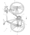
図1を参照して、自転車1(特に、競走用の自転車)は、既知の方法で筒体から形成されたフレーム2を備える。フレーム2は、後輪4の軸支持構造3および前輪6のフォーク5を形成する。筒状構造のハンドルバー41は、フォーク5およびフレーム2に動作可能に連結している。
Referring to FIG. 1, a bicycle 1 (particularly a racing bicycle) includes a
フレーム2は、その下方部分において、一般的な種類のペダルクランク(ペダルユニット)7の軸を支承する。このペダルクランク(ペダルユニット)7は、概して符号8で示される本発明の電子サーボ支援型のギアシフト装置を介して後輪4を駆動する。
The lower part of the
ギアシフト装置8は、後側のギアシフト群9および前側のギアシフト群10を含む。後側のギアシフト群9は、後輪4と同軸上に位置した、径の異なる複数の歯車(スプロケット)11を有する。前側のギアシフト群10は、ペダルクランク7の軸と同軸に位置した、径の異なる複数の歯車、クラウンまたはギアホイール12を有する。
The
後側のギアシフト群9の歯車11および前側のギアシフト群10の歯車12には、閉ループ状の伝動チェーン13が、電子サーボ支援型のギアシフト装置8を介して選択的に係合可能であり、これにより、様々なギア比を実現することができる。
A closed
このような様々なギア比は、後側のギアシフト群9の後側のディレイラ14のチェーン案内要素(ケージ)、および/または前側のギアシフト群10の前側のディレイラ15のチェーン案内要素(ケージ)を移動させることによって得られる。
Such various gear ratios cause the chain guide element (cage) of the
各ディレイラ14,15において、後側および前側のチェーン案内要素は、それぞれ、後側の電気モータ16、前側の電気モータ17(図2)によって移動させられる。典型的に、電気モータ16,17には減速機が設けられており、かつ、関節型の平行四辺形リンク機構を介してチェーン案内要素に接続されている。あるいは、当該技術分野において周知である他の種類のモータまたは他の種類のアクチュエータまたはリンク機構、例えば、ラック機構、ウォームねじ機構などを使用してもよい。例えば、米国特許第6679797号明細書に記載されたものを使用してもよい。なお、この米国特許の教示内容は、参照をもって本明細書に取り入れたものとする。
In each
典型的に、ディレイラ14,15は、それぞれの位置および/または速度および/または加速度の後側のセンサ18,前側のセンサ19(図2)をそれぞれ有する。センサ18,19は、モータ16,17のロータ、または当該ロータからチェーン案内要素に至るまでの下流領域に位置する任意の可動部品に接続されてもよい。
Typically, derailleurs 14 and 15 have a
ディレイラの詳細な構造は本発明の範囲外であるので、本明細書ではディレイラ14,15の構造の詳細を図示しない。ディレイラの構造の詳細については、例えば前記特許文献1、2および米国特許第6679797号明細書などを参照されたい。
Since the detailed structure of the derailleur is outside the scope of the present invention, details of the structure of the
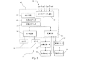
図2は、本発明の実施形態にかかる電子サーボ支援型のギアシフト装置の電気的・電子的構成を示すブロック図である。 FIG. 2 is a block diagram showing an electrical / electronic configuration of the electronic servo-assisted gear shift device according to the embodiment of the present invention.
電源ユニットつまり電源基板30にはバッテリが設けられており、これによりモータ16,17、ディレイラ14,15のセンサ18,19、および後述するインタフェースユニットつまりインタフェース基板32である電子基板に電力を供給し、任意で、後述するセンサ基板つまりセンサユニット34である電子基板にも給電する。好ましくは、このバッテリは充電可能なタイプである。また、後側のディレイラ14は、前述のバッテリを充電するために発電ユニット(ダイナモユニット)を周知の形態で有していてもよい。図2において、給電線は簡略化のため図示していない。
A battery is provided in the power supply unit, that is, the
電源基板30、インタフェースユニット32およびセンサユニット34が全体として、電子サーボ支援型のギアシフト装置8の電子コントローラつまり電子制御部40を構成する。代わりに、1枚の電子基板または異なる枚数の電子基板があってもよい。
The
したがって、本明細書および添付の特許請求の範囲において電子コントローラつまり電子制御部40とは、論理的なユニットのことを指す。この論理的なユニットは、複数の物理的なユニットないしモジュール、特には、一つ以上の分散したマイクロプロセッサで構成されてもよい。このような一つ以上の分散したマイクロプロセッサは、例えば、電源基板30および/またはインタフェースユニット32および/またはセンサユニット34に含まれることができる。
Therefore, in this specification and the appended claims, the electronic controller, that is, the
電源基板30は、例えば、ハンドルバー41を構成するチューブのうちの一つの内部、またはフレーム2を構成するチューブのうちの一つ(例えば、ドリンクボトル(図示せず)の支持部分)の内部に収容される。インタフェースユニット32は、例えば、ハンドルバー41を構成するチューブのうちの一つの内部、またはハンドルバー41に装着された把持可能な装置または手動制御装置42に収容される。センサ基板34は、例えば、フレーム2を構成するチューブのうちの一つの内部において、当該センサ基板34に接続されるセンサの近傍に収容される。
The
各種構成品に対する電力、データおよび情報の伝達は、電気ケーブルを介して実行される。好ましくは、前述の電気ケーブルは、フレーム2を構成するチューブの内部に収容される。データおよび情報信号の伝達は、例えばBluetooth(登録商標)プロトコルなどのワイヤレスモードで実行されてもよい。
Transmission of power, data and information to various components is performed via electrical cables. Preferably, the above-described electric cable is accommodated in a tube constituting the
走行時、後側および前側のディレイラ14,15は、手動制御装置42で入力されるアップシフト要求信号またはダウンシフト要求信号に基づいて電子制御部40によって制御されるか、または電子制御部40によって半自動制御もしくは自動制御される。手動制御装置42は、例えば、インタフェースユニット32に接続または配置されたスイッチ36の状態を切り替えるのに適したレバーまたはボタンを有してもよい。スイッチ36は、直接作動可能であってもよく、スイッチごとのレバーによって作動可能なものであってもよく、あるいは、スイングレバーによって二つのボタンが作動可能なものであってもよい。
When traveling, the rear and
典型的には、ハンドルバー41の一方のハンドグリップ自体またはその近傍にレバーまたはボタン(図2)が、後側のギアシフト群9のアップシフト信号およびダウンシフト信号のために配置され、ハンドルバー41の他方のハンドグリップ自体またはその近傍にレバーまたはボタンが、前側のギアシフト群10のアップシフト信号およびダウンシフト信号のために配置される。典型的には、例えば動作モードの選択などといった、補助的な機能を制御するための一つ以上のスイッチ36を作動するレバーまたはボタンがさらに設けられている。
Typically, a lever or button (FIG. 2) is arranged on or near one handgrip of the
好ましくは、ギアシフト装置8の電子制御部40(より詳細には、センサユニット34)には、走行速度、ペダルクランクの回転速度、走行地形の傾斜、サイクリストの心拍数などといった走行パラメータの一つ以上のセンサ38が接続されている。
Preferably, the electronic control unit 40 (more specifically, the sensor unit 34) of the
実施形態において、電子制御部40は、ギアシフトを作動するにあたって、モータ16,17を作動し、所望のギア比に達した際、すなわち、チェーン13が所望の歯車11,12と正確に係合する位置にディレイラ14,15のチェーン案内要素が達した際に、センサ18,19の信号に基づいて、モータ16,17を停止させる。前述の所望の歯車11,12は、例えば、ギアシフト指令(アップシフト指令またはダウンシフト指令)が手動制御装置42およびスイッチ36によって生成された際、および/またはギアシフト指令(アップシフト指令またはダウンシフト指令)が走行パラメータについてのセンサ38の出力に基づいて電子制御部40によって生成された際にチェーン13が位置していた歯車に隣接する歯車(大径の歯車または小径の歯車)である。多段ギアシフトの場合、前述の所望の歯車は、必ずしもギアシフト開始位置の歯車に隣接する歯車ではない。
In the embodiment, the
実施形態の変形例では、モータ16,17は、一定時間またはいくつかのステップにわたって、駆動されるものであり、または各種アップシフトまたは各種ダウンシフトに応じた適切な電圧値で駆動され、その後、自動的に停止する。センサ18,19は任意の構成要素とされ、電子制御部40に対してフィードバック信号を供給するのに使用される。これにより、電子制御部40は、チェーン13を所望の歯車11,12に係合させる物理的位置にモータ16,17が達していない場合に当該モータ16,17を再び作動させることができる。これは、例えば、ディレイラ14,15の抵抗トルク(サイクリストのペダル動作にある程度依存する)が、モータがリンク機構を介して生成可能な最大トルクを超えるほど過度に大きくなることによって生じる。
In a variation of the embodiment, the
モータ16,17は、例えば、ステッピングモータである。好ましくは、モータ16,17は、適切な数の「ステップ」によって駆動される直流ブラシモータであり、当該適切な数の「ステップ」の各ステップは、何分の一回転に相当し、好ましくは32分の一回転に相当する。このように32分の一回転をステップとして選択すると、ステップは2の整数倍であるため、有利に処理を実行することができる。
The
電子制御部40は、さらに、メモリ手段44を含み、電子制御部40は、このメモリ手段44に基づいて、所望の歯車11,12に係合する位置にチェーン13を移動させるためのアクチュエータに対する指令値を、その時々に応じて決定する。
The
電子制御部40は、後側のカウンタ46および前側のカウンタ48を備えることができる。カウンタ46,48は各々、例えば、レジスタで構成されてもよく、メモリセルに記憶された変数で構成されてもよい。ギアシフト装置8の通常走行動作モード時における電子制御部40は、ディレイラ14,15を駆動し、例えば、モータ16,17に1ステップ印加されるごとに測定単位の1単位、カウンタ46,48を増減することによって、および/またはセンサ18,19の読み値に基づいて、ディレイラ14,15の現在の位置を追跡する。カウンタ46,48が設けられる場合、カウンタ46,48は、メモリ手段44に記憶された指令値と同じ測定単位でディレイラ14,15の現在の位置を表す。この場合、カウンタ46,48はセンサ18,19としても働く。
The
指令値のメモリ手段44、およびカウンタ46,48は、電子制御部40内の自立した(別個の)構成部として図示されているが、電子基板30,32,34に含まれる一つ以上のメモリ装置に物理的に設けられてもよい。
Although the command value memory means 44 and the
より単純な自転車では、電子制御部40は後側のギアシフト群9および前側のギアシフト群10のうちの一方のみを設けてもよく、前述した自転車からの簡略化は当業者にとって明白である。
In a simpler bicycle, the
説明を簡単にするために、以下では、特に、後側のギアシフト群のみを扱う。後述の内容は、代替的に、あるいは、追加的に、適宜変更を加えたうえで、前側のギアシフト群にも適用可能である。 In order to simplify the description, only the rear gear shift group will be dealt with in the following. The contents to be described later can be applied to the front gear shift group as appropriate instead or in addition.
図3に、電子制御部40のメモリ領域(例えば、前述のメモリ手段44など)または電子制御部40がアクセス可能な任意のメモリに記憶されるデータ構造を示す。このメモリ領域または任意のメモリには、ギアシフト群の歯車(スプロケット)ごとに、アクチュエータに対する指令値Qi(iは1〜Nの整数である)がテーブル60の形態で記憶される。一実施例としての、11個のスプロケットを有する後側のギアシフト群9の場合、前述のテーブル60は、指令値Q1〜Q11を有する。
FIG. 3 shows a data structure stored in a memory area of the electronic control unit 40 (for example, the
詳細に述べると、指令値Q1は、後側のギアシフト群9の最小径を有するスプロケット11に係合する物理的位置にチェーン13が位置した、ギアシフトにおける理論上の状態を、適切な測定単位で表したものである。指令値Q2は、後側のギアシフト群9の前述の最小径を有するスプロケット11に隣接するスプロケット11に係合する物理的位置にチェーン13が位置した状態を、前述の測定単位と同じ測定単位で表したものである。例えば、指令値QN(図示の例ではQ11)は、後側のギアシフト群9の最大径を有するスプロケット11に係合する物理的位置にチェーン13が位置した状態を、前述の測定単位と同じ測定単位で表したものである。
More specifically, the command value Q 1 represents the theoretical state in the gear shift in which the
好ましくは、指令値Qiは、標準または基準となるギアシフトを指す「公称値」と呼ばれる値として工場で記憶され、後で、「実際の値」と呼ばれる値として調整され、例えば、衝撃または衝突、または、交換前の歯車および交換後の歯車の寸法および/または位置のわずかなずれのみならず、フレームの構成品の寸法の違いやギアシフト装置の取付公差、および公称値の基礎となる理論的な基準ギアシフト装置を基準とした歯車組立体内の寸法の違いに起因するチェーン13と一つ以上の歯車11との間の位置ずれも考慮に入れられる。
Preferably, the command value Q i is stored at the factory as a value called “nominal value” that refers to a standard or reference gear shift and later adjusted as a value called “actual value”, eg, impact or collision , Or the theoretical basis of not only slight deviations in the dimensions and / or position of the gears before and after the replacement, but also the differences in the dimensions of the frame components, the mounting tolerances of the gear shift device, and the nominal values. The misalignment between the
例えば、各指令値Qiは、センサ18の出力が取るべき値であって、任意でカウンタ46に記憶される値であってもよい。指令値Qiは、また、モータ16の駆動量の値として表されてもよい。
For example, each command value Q i may be a value that the output of the
例えば、既述したようにアクチュエータがステッピングモータを有する場合、すなわち、何分の一回転で駆動されるモータを有する場合、指令値Qiは、それぞれ、i番目の歯車との係合状態に達するために必要なステップ数として表されてもよく、基準位置から開始する。基準位置として、例えば、ストロークの終了位置、モータ16が励磁されていない状態、最小径を有する歯車との係合状態などに相当する。
For example, as described above, when the actuator has a stepping motor, that is, when it has a motor driven by a fraction of a revolution, each of the command values Q i reaches the engaged state with the i-th gear. It may be expressed as the number of steps required to start from a reference position. The reference position corresponds to, for example, an end position of a stroke, a state where the
また、指令値Qiは、それぞれ、アクチュエータの特定の移動点の位置、チェーン案内要素の特定の移動点の位置として、または基準平面(例えば、自転車に沿った基準平面)からそのような移動点までの距離(例えば、mm単位の距離)として、基準歯車との係合状態において表されてもよい。また、指令値Qiは、それぞれ、その電圧に比例する、チェーン13の運動を引き起こす、モータ16への給電電圧の値として表されてもよく、あるいは、アクチュエータの種類に応じて当業者にとって既知の他の形態で表されてもよい。
In addition, the command value Q i is the position of a specific movement point of the actuator, the position of a specific movement point of the chain guide element, or such a movement point from a reference plane (for example, a reference plane along the bicycle), respectively. May be expressed in the engaged state with the reference gear (for example, a distance in mm). Further, each of the command values Q i may be expressed as a value of a power supply voltage to the
また、指令値Qiは、それぞれ、当業者によって理解されるように、アクチュエータの種類に応じて、隣接する歯車に対する異なる方法で表されてもよく、例えば、移動距離、実行すべきステップ数、アクチュエータの作動時間で表されてもよい。詳細には、この場合、各歯車に係る指令値は、直ぐ隣の小径の歯車から開始する指令値、および直ぐ隣の大径の歯車から開始する指令値となる。この場合に必要な変更は、当業者の能力の範疇である。より精巧な実施形態では、歯車ごとに、また、当該歯車にチェーンが達する際の方向ごとに、係合動作を行うにあたって一時的にチェーンを位置決めするための指令値とともに、チェーンの係合が成功する位置に当該チェーンを移動させるための指令値を用意してもよい。 Also, each command value Q i may be expressed in different ways for adjacent gears depending on the type of actuator, as will be understood by those skilled in the art, for example, the travel distance, the number of steps to be performed, It may be represented by the operating time of the actuator. Specifically, in this case, the command value for each gear is a command value starting from the immediately adjacent small diameter gear and a command value starting from the immediately adjacent large diameter gear. The necessary changes in this case are within the abilities of those skilled in the art. In more elaborate embodiments, for each gear and for each direction that the chain reaches the gear, the chain is successfully engaged with a command value for temporarily positioning the chain in performing the engaging operation. You may prepare the command value for moving the said chain to the position to perform.
理解し易いように、以下では、指令値Qiを、比例的に増減する測定単位で表すものとする。 For ease of understanding, the command value Q i will be expressed in the following units of measurement that increase or decrease proportionally.
図3のテーブル60は、1〜Nの数値(図示の例では1〜11)のフィールドiも示す。しかし、実際の用途では、指令値Qiが対応する歯車の径順に並んで記憶される場合、このフィールドを省略してもよいことが理解されよう。事実、後述するように、特定の指令値Qiを得るたび、現在のインデックスi=1…Nの数値に基づいてテーブル60が参照される。したがって、指令値Qiが順番に並べられている場合、テーブル60のi番目の数値を参照するだけでよい。
The table 60 of FIG. 3 also shows a field i of
図2にはメモリ手段44を一つだけ概略的に示したが、実際には、種々の記憶装置が設けられてもよいことが理解されよう。好ましくは、公称の指令値Qiは、EEPROMメモリまたは読出し専用メモリ(例えば、ROMなど)に記憶され、実際の指令値は、同じEEPROMメモリ、それとは別のEEPROMメモリ、または読出し/書込みメモリに記憶される。 Although only one memory means 44 is shown schematically in FIG. 2, it will be understood that in practice various storage devices may be provided. Preferably, the nominal command value Q i is stored in an EEPROM memory or a read-only memory (eg ROM), and the actual command value is stored in the same EEPROM memory, a separate EEPROM memory, or a read / write memory. Remembered.
より明瞭にするために指令値Qiの単一のテーブルが示されているが、公称の指令値と実際の指令値の両方が共通のデータ構造または区分したテーブルに記憶されてもよい。 Although a single table of command values Q i is shown for clarity, both nominal and actual command values may be stored in a common data structure or partitioned table.
本明細書では、実際に使用する場合、公称の指令値と実際の指令値との指令値が参照される。公称の指令値および実際の指令値の二つの分類したテーブルが存在しているが、単一のテーブル60が参照される。 In this specification, when actually used, reference is made to a command value between a nominal command value and an actual command value. There are two classified tables of nominal command values and actual command values, but a single table 60 is referenced.
通常走行動作モード時に、i番目の歯車にチェーン13が係合するようにギア比の変更を実行する必要がある場合、電子制御部40は、i番目の歯車に係る指令値Qiをテーブル60から読み出し、それに応じてアクチュエータ、具体的には、モータ16を駆動する。
When it is necessary to change the gear ratio so that the
具体的に、モータ16がステッピングタイプ、すなわち、既述したように各ステップが何分の一回転に相当する複数の「ステップ」によって作動されるタイプの場合、モータ16は、一回に1ステップずつ運動するように駆動されるか、あるいは、一回に複数ステップずつ運動するように駆動される。
Specifically, when the
好ましくは、指令値Qiに対する基準システムの起点はA番目の第1の歯車、Q1=0において、選択される。 Preferably, the starting point of the reference system for the command value Q i is selected at the A-th first gear, Q 1 = 0.
大きい直径を有する歯車側にシフトする場合、指令値は増加し、または小さい直径を有する歯車側にシフトする場合、指令値は減少することが分かる。 It can be seen that the command value increases when shifting to the gear side having the larger diameter, or the command value decreases when shifting to the gear side having the smaller diameter.
以下に詳細に説明される本発明による制御方法は、歯車、チェーン、およびギアシフト装置の他の構成品とは別個に、ディレイラと共に販売される電子制御部において、実施することができる。 The control method according to the invention described in detail below can be implemented in an electronic control unit sold with the derailleur separately from the gears, the chain and the other components of the gearshift device.
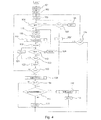
本発明によるギアシフト装置8の電子制御について、本発明の実施形態による例示的なフロー図を示す図4と、図4のフロー図に基づいて制御される電子サーボ支援型のギアシフト装置8の動作を概略的に示したタイムチャートである図5〜図10と、を参照して説明する。
Regarding the electronic control of the
ブロック101において、チェックカウンタNCは、ディレイラの位置が所望位置、すなわち、ギアシフトのデフォルト位置、または、最後に実行されたギアシフトに基づく位置である、制御の最大値、すなわち、チェック回数の最大値MAXCに、初期化される。チェック回数の最大値MAXCは、ブロック118に関連して後述する。チェック回数の最大値MAXCは、二つの連続チェックの間の時間周期MAX2の値と共に、実験的には、ギアシフトモデルにおいて観察された、速度と予期しない運動時間全体との関数として、選択される。時間周期MAX2についてはブロック118に関連して後述する。このような時間と速度は、アクチュエータとチェーン案内要素との間に配置されたリンク機構の弾性の関数である。チェック回数の最大値MAXCは、例えば、数十回から選択される。
In
より具体的には、所望位置は、上記したように、ディレイラの予め選択された変数がテーブル60の所定の指令値Qiを取る位置であり、これによって、伝動チェーン13が目標のi番目の歯車11、12と係合するように位置決めすることができる。このi番目の歯車は、例えば、スイッチオンされる状態では最小径を有する歯車(テーブル60によれば、i=1)であり、単一のギアシフトアップした後では前に係合していた歯車11(テーブル60によれば、インデックスi′)のシフトアップ方向のとなりの歯車(テーブル60によれば、インデックスi=i′+1)であり、単一のギアシフトダウンした後では、前に係合していた歯車11のシフトダウン方向のとなりの歯車(テーブル60によれば、インデックスi=i′−1)である。また、複数のギアのシフトアップまたはシフトダウンの場合はそれぞれのとなりではない歯車である。
More specifically, as described above, the desired position is a position where a preselected variable of the derailleur takes a predetermined command value Q i in the table 60, whereby the
次のブロック102において、再位置決め動作カウンタNRは、ディレイラが所望位置に整合していないときに実行されるディレイラの再位置動作回数の最大値MAXRに初期化される。再位置決め動作回数の最大値MAXRは、一方では、ディレイラの位置をできるだけ正確に維持するが、他方では、機械部品に過度の負荷を掛けずに電気エネルギを保存することで電子制御部40をオーバーロードさせないという、相反する要件に基づいて、選択される。再位置決め動作回数の最大値MAXRは、例えば、数回から選択される。再位置決め動作回数の最大値MAXRが高すぎると、ディレイラの機械部品へ過度な負荷を掛けるだけでなく、バッテリの過剰消費につながる。数回の再位置決め動作を行った後は、再位置決め動作を行わず、サイクリストが伝動システムが適正に実行されてないことに気づいて、ギア比を変更するのを待つのが好ましい。
In the
好ましくは、再位置決め動作回数の最大値MAXRはチェック回数の最大値MAXCを下回る。 Preferably, the maximum value MAXR of the number of repositioning operations is less than the maximum value MAXC of the number of checks.
次のブロック103において、カウンタまたは第1タイマT1は、第1の時間周期を表す値MAX1に初期化され、その後、一つのギアシフトと他のギアシフトとの間において、ディレイラの位置が所望位置であるか否かのチェックを行うことが望まれる。
In the
本発明の導入部分で説明したように、ディレイラの位置が所望位置に留まらない場合がる。この位置は、ディレイラに伝えられた動きの間に、たとえ、微量であっても所望されない動きが伝達されて到達した位置である。 As described in the introduction part of the present invention, the position of the derailleur may not stay at the desired position. This position is a position where an undesired movement is transmitted even if it is a minute amount during the movement transmitted to the derailleur.
第1の時間周期MAX1は、ブロック118に関して以下に記載する第2の時間周期MAX2に対して比較的長い。そのため、本発明の開示の他の部分および添付クレームにおいて、比較的長いタイマT1、比較的長い時間周期MAX1、比較的短いタイマT2、および比較的短い周期MAX2という表現が使用されることがある。 The first time period MAX1 is relatively long relative to the second time period MAX2 described below with respect to block 118. As such, in other parts of the present disclosure and appended claims, the expressions relatively long timer T1, relatively long time period MAX1, relatively short timer T2, and relatively short period MAX2 may be used.
第1の時間周期MAX1は、例えば、数十秒から選択することができる。第1の時間周期MAX1は適切な尺度で表すことができる。 The first time period MAX1 can be selected from several tens of seconds, for example. The first time period MAX1 can be expressed on an appropriate scale.
次のブロック104において、ギアシフト要求信号があるか否かがチェックされる。既述したように、この信号は、走行パラメータのセンサ38の出力に基づいて、サイクリストまたは電子制御部40によって自動生成される。
In the
ブロック104においてチェックが否定判定の場合、ブロック105において、第1の時間周期MAX1を経過したか否か、すなわち、図示した実施形態において、第1タイマT1がカウントダウンを終了し、よって、T1=0であるか否かがチェックされる。
If the check is negative in
第1の時間周期MAX1が経過しなかった場合、すなわち、ブロック105において否定判定の場合、ブロック106において、タイマT1の値は、典型的に、第1の時間周期MAX1と同じ時間量だけ減少され、ブロック104に戻り、ギアシフト要求信号があるか否かがチェックされる。
If the first time period MAX1 has not elapsed, i.e. a negative determination at
第1の時間周期MAX1の経時中にギアシフト要求信号がない場合、このような時間周期MAX1の終了時に、第1のタイマT1はカウントダウンを終了してT1=0が真になり、ブロック105からYES(肯定判定)が出力される。 If there is no gear shift request signal during the lapse of the first time period MAX1, at the end of such time period MAX1, the first timer T1 finishes counting down and T1 = 0 becomes true, and YES from block 105 (Positive determination) is output.
この場合、ブロック107において、チェックカウンタNCの値はゼロ(0)に設定される。ゼロ(0)値は、ブロック図4において便宜上チェックカウンタNC上で設定されるが、すぐにお分かりのように、このようなチェックカウンタNCの値であっても実際には位置のチェックが実行される。あるいは、比較的低速な時間周期MAX1がギアシフト要求および作動せずに経時されたことを示すために別のフラグを使用することが可能である。ブロック107の後、ブロック108において、各々のセンサ18、19の出力を読み出すことによってディレイラの実際の位置が得られる。
In this case, in
次のブロック109において、後述するブロック113において減少される再位置決め動作カウンタNRが現在ゼロ(0)か否かをチェックする。
In the
否定判定の場合、ブロック109の初期実行におけるように、次のブロック110において、適切な所定の許容範囲から外れて、ディレイラの実際の位置が所望位置に対応するか否かをチェックするが、これもゼロ(0)であり得る。
In the case of a negative determination, as in the initial execution of
肯定判定の場合、補正処理は必要がなく、再位置合わせ動作カウンタNRの値は、ブロック111において再位置合わせ動作回数の最大値MAXRに戻されるか、または、減少されない場合、再確認される。
If the determination is affirmative, no correction process is required, and the value of the realignment operation counter NR is returned to the maximum value MAXR of realignment operations in
ディレイラの実際の位置が所望位置に対応せず、このような所望位置の周囲で可能な所定の許容範囲から外れている場合(ブロック110の否定判定)、ディレイラが所望位置に整合するまで、ブロック112において、上述したようにフィードバック信号としてセンサ18、19の出力をできる限り活用して、アクチュエータのモータ16、17を作動させる。
If the actual position of the derailleur does not correspond to the desired position and deviates from the predetermined allowable range around such a desired position (determination of block 110), the block until the derailleur is aligned with the desired position. At 112, as described above, the
ディレイラが所望位置に整合するとすぐに、ブロック113において再位置決め動作カウンタNRの値が測定単位の1単位減少される。
As soon as the derailleur is aligned with the desired position, in
なお、センサ18、19からのフィードバック信号が存在ない場合、ブロック112の終了時に、ディレイラが所望位置に整合しているとされることに留意されたい。
Note that if there are no feedback signals from
ブロック110におけるディレイラの実際の位置が所定の許容範囲から外れた所望位置にあるか否かのチェックの結果とは無関係に、ブロック111、112、113それぞれの後、ブロック114においてチェックカウンタNCが、現在、ゼロ(0)であるか否かをチェックされる(後述するブロック122において減少され得る)。
Regardless of the result of checking whether the actual position of the derailleur in
なお、ディレイラの実際の位置が所定の許容範囲から外れた所望位置にあるか否かがチェックされるブロック110でのチェックが、再位置合わせ動作カウンタNRの不足(ブロック109の肯定判定)が原因で、実行されない場合に、同じブロック114に進むことに留意されたい。
The check in
例えば、現在検討されている、時間周期MAX1中にギアシフト要求指令を受信しなかった場合に発生するように、チェックカウンタNCがゼロ(0)の場合、ブロック114においてチェックカウンタNCがゼロ(0)に設定されているので、比較的長いタイマT1が最大値MAX1にリセットされるブロック103、その後、ギアシフト要求信号があるか否かがチェックされるブロック104へ戻る。
For example, if the check counter NC is zero (0), as it occurs if the gear shift request command is not received during the time period MAX1, which is currently being considered, the check counter NC is zero (0) at
他の仮定に基づいてブロック図4の記述に進行する前に、比較的長い時間周期MAX1の間の任意の指令を受信しなかった場合の動作について図5〜図7の概略的なタイムチャートにまとめ、これを参照する。このようなタイムチャートにおいて、チェック回数の最大値MAXCは3回であり、再位置合わせ動作回数の最大値MAXRは2回であるとする。 Based on other assumptions, before proceeding to the description of the block diagram of FIG. 4, the operation when no command is received during the relatively long time period MAX1 is shown in the schematic time charts of FIGS. Summarize and refer to this. In such a time chart, it is assumed that the maximum value MAXC of the number of checks is 3 times and the maximum value MAXR of the number of realignment operations is 2 times.
図5は、比較的長い時間周期MAX1を経過した後、位置の読み出し(ブロック108)が許容範囲内である(ブロック110が肯定判定)場合を示している。その後、他の比較的長い時間周期MAX1を待機し、その後、位置の他の読み出しが行われる(ここでも許容範囲内であるとする)。チェックカウンタNCが常時ゼロ(0)ダミー値に戻されるので、以上の状況が無限に繰り返される。 FIG. 5 shows a case where the position reading (block 108) is within an allowable range after a relatively long time period MAX1 has elapsed (block 110 is positively determined). After that, another relatively long time period MAX1 is waited, and then another reading of the position is performed (again, it is within the allowable range). Since the check counter NC is always returned to the zero (0) dummy value, the above situation is repeated infinitely.
図6は、比較的長い時間周期MAX1を経過した後、位置の読み出し(ブロック108)は許容範囲外である(ブロック110の否定判定)の場合を示している。したがって第1の再位置決めが実行され(ブロック112)、再位置決め動作カウンタNRの値を測定単位の1単位減少し(ブロック113)、その後、他の比較的長い時間周期MAX1を待機し、その後、位置の他の読み出し(今回は許容範囲内であるとする)を行う。その後、この再位置決め動作カウンタNRを再位置決め動作回数の最大値MAXRに戻す(ブロック111)。上述したように、チェックカウンタNCもゼロ(0)のダミーの値(ブロック107)に戻されるので、以上に述べた状況が無限に繰り返される。 FIG. 6 shows a case where the position reading (block 108) is out of the allowable range (determination of block 110) after a relatively long time period MAX1 has elapsed. Accordingly, the first repositioning is performed (block 112), the value of the repositioning operation counter NR is decreased by one unit of measurement (block 113), then waiting for another relatively long time period MAX1, and then Another reading of the position (assuming this time is within the allowable range) is performed. Thereafter, the repositioning operation counter NR is returned to the maximum value MAXR of the number of repositioning operations (block 111). As described above, since the check counter NC is also returned to the dummy value (block 107) of zero (0), the above-described situation is repeated infinitely.
最後に、図7は、第1の比較的長い時間周期MAX1の後、位置の読み出し(ブロック108)が許容範囲外である(ブロック110の否定判定)場合を示している。よって、第1の再位置決めが実行され(ブロック112)、再位置決め動作カウンタNRの値を測定単位の1単位減少し(ブロック113)、その後、第2の比較的長い時間周期MAX1を待機し、その後、位置の他の読み出しを行う(ここでも再び否定判定される)。その後、第2の再位置決めが実行され、再位置決め動作カウンタNRの値を測定単位の1単位減少する。再位置決め動作回数の最大値MAXRが2回とすると、すなわち、記述したように再位置決め動作回数の最大値MAXRの後、再位置決め動作カウンタNRはゼロ(0)に達する。第3の比較的長い時間周期MAX1を待機した後、位置の他の読み出しが実行される(ブロック108)が、その位置が許容範囲内にあるか否かはチェックしない(ブロック109において肯定判定)、そして、いずれにせよ、再位置決め動作は実行されない。チェックカウンタNCがあらゆる比較的長い時間周期MAX1を経た後で、ゼロ(0)のダミー値に戻るので、この最終的な状況が無限に繰り返される。すなわち、その位置が時間周期MAX1をもってチェックされた場合でも、次のギアシフトまで、ディレイラは非所望位置にとどまる。 Finally, FIG. 7 shows the case where the position reading (block 108) is outside the acceptable range (determination of block 110) after the first relatively long time period MAX1. Thus, the first repositioning is performed (block 112), the value of the repositioning operation counter NR is decreased by one unit of measurement (block 113), and then waiting for the second relatively long time period MAX1, Thereafter, another reading of the position is performed (again, a negative determination is again made). Thereafter, the second repositioning is executed, and the value of the repositioning operation counter NR is decreased by one unit of measurement. When the maximum value MAXR of the number of repositioning operations is 2, that is, after the maximum value MAXR of the number of repositioning operations as described, the repositioning operation counter NR reaches zero (0). After waiting for the third relatively long time period MAX1, another read of the position is performed (block 108), but does not check whether the position is within an acceptable range (positive determination at block 109). In any case, the repositioning operation is not performed. This final situation is repeated indefinitely since the check counter NC returns to a dummy value of zero (0) after every relatively long time period MAX1. That is, even if the position is checked with the time period MAX1, the derailleur remains in the undesired position until the next gear shift.
実際、上述したように、再位置決め動作回数の最大値MAXRに達した後、機械部品に負荷をかけないためおよび電力を過剰に消費しないためにディレイラ15をさらに移動させずに、むしろ、サイクリストによる介入を待機する方が好ましい。したがって、実際の位置が許容範囲内にあるか否かのチェック(ブロック110)も省略される。逆に、いずれにせよ、ブロック108において、ディレイラの実際の位置を読み出し、この位置を追跡し、したがって正確な起点を得て、必要に応じて、テーブル60で読み出された指令値を補正することができる。特に、異なる方法で駆動されたディレイラの場合に有効である。
In fact, as described above, after reaching the maximum value MAXR of the number of repositioning operations, the
ディレイラ15の非差動指令値の場合、ディレイラ15の実際の位置の追跡を省くことができる。この場合、ブロック108および109はその位置を反転させることができ、(そして、関連する出力が結果的に調整される)、よって、再位置決めの動作回数NRを使い切った場合、実際の位置の読み出しを省くことができる。
In the case of the non-differential command value of the
逆に、実際の位置を読み出した後、実際の位置が許容範囲内にあるかがチェックされる。すなわち、再位置決めの動作回数NRを使い切ったか否かのチェック(ブロック109)を、再位置決めブロック112の直前に、位置が許容範囲内にあるか否かのチェックを行うブロック110の否定判定へ移動させることによって、実行することができる。
Conversely, after reading the actual position, it is checked whether the actual position is within the allowable range. That is, the check (block 109) of whether or not the repositioning operation frequency NR has been used is moved to the negative determination of the
例えば、いったん再位置決めの動作回数の最大値を超えると、否定判定カウンタおよびサイクリストへ適切なアラーム信号を実装することも可能である。実際、このような状況は、特に深刻でないが(許容範囲から少し外れる位置)、ギアシフトの機械部品またはテーブル60の指令値の見直しをしてもよい。 For example, once the maximum number of repositioning operations has been exceeded, an appropriate alarm signal can be implemented in the negative decision counter and cyclist. In fact, such a situation is not particularly serious (a position slightly outside the allowable range), but the gear shift mechanical part or the command value of the table 60 may be reviewed.
図4のブロック図に戻って参照するに、比較的長い時間周期MAX1の経時中、ギアシフト要求信号がある場合(ブロック104が肯定判定された場合)、ブロック115および116において、最初に、チェックカウンタNCおよび再位置決め動作カウンタNRは、許容されたそれぞれの最大値MAXCおよびMAXRへ戻される、またはこれらが減少しない場合は再確認される。
Referring back to the block diagram of FIG. 4, if there is a gear shift request signal over the course of a relatively long time period MAX1 (if
その後、ブロック117において、アクチュエータのモータ16,17は、ディレイラが所望位置(別の歯車における新しい所望位置)に整合するまで作動する、このとき、上記したように、センサ18,19の出力をフィードバック信号としてできる限り利用する。
Thereafter, in
ディレイラが所望位置に整合されるとすぐに、ブロック118において、カウンタまたは第2のタイマT2は比較的短い時間周期MAX2に初期化される。この比較的短い時間周期MAX2は、第2の時間周期を表し、この時間周期の経過後、ディレイラの位置が所望位置であるか否かのチェックの実行が望ましい。さらに、この場合、ディレイラの位置は、上述したように、ディレイラ15のリンク機構の弾性および/または路面の凸凹に起因する振動によって生じる、微量であるが所望されない動きに影響されて、所望位置にとどまらないことがある(この位置はギアシフトを実行する(ブロック117)ときにディレイラに所望されない動きが伝達されて到達した位置である)。
As soon as the derailleur is aligned to the desired position, at
なお、センサ18,19からフィードバック信号がない場合、ブロック117の終了時にディレイラが所望位置に整合されることに留意されたい。
Note that in the absence of feedback signals from
既述したように、本出願人は、ギアシフト直後、ディレイラの望ましくない微小変位が発生しやすいことに気づいたので、第2の時間周期MAX2は比較的短い。 As described above, since the present applicant has noticed that an undesirable minute displacement of the derailleur is likely to occur immediately after the gear shift, the second time period MAX2 is relatively short.
第2の時間周期MAX2は、例えば、数十分の1秒単位で選択することができる。好ましくは、第2の時間周期MAX2は、第1の時間周期MAX1と同じ測定単位の適切な測定単位で表すことができる。 The second time period MAX2 can be selected in units of several tens of seconds, for example. Preferably, the second time period MAX2 can be expressed in a suitable measurement unit of the same measurement unit as the first time period MAX1.
次のブロック119において、(第2の)ギアシフト要求信号があるか否かがチェックされる。
In the
ブロック119のチェックが否定判定された場合、ブロック120において、第2の時間周期MAX2が経過したか否か、すなわち、図4に示した実施形態では、第2のタイマT2がカウントダウンを終了して、T2=0であるか否かがチェックされる。
If the check at
第2の時間周期MAX2を経過しなかった場合、ブロック120は否定判定され、ブロック121において、タイマT2の値は、典型的に第2の時間周期MAX2と同じ尺度で測定単位の1単位減少され、その後、ブロック119に戻り、(第2の)ギアシフト要求信号があるか否かをチェックする。
If the second time period MAX2 has not elapsed, block 120 is negatively determined, and at
第2の時間周期MAX2の経時中に(第2の)ギアシフト要求信号がない場合、このような時間周期MAX2の終了時に、第2のタイマT2がカウントダウンを終了して、T2=0が真となり、ブロック120が肯定判定される。
If there is no (second) gear shift request signal during the second time period MAX2, the second timer T2 finishes counting down at the end of such time period MAX2, and T2 = 0 becomes true.
この場合、ブロック122において、チェックカウンタNCの値が測定単位の1単位減少され、その後、ブロック123において、チェックカウンタNCの値が現在ゼロ(0)であるかをチェックする。
In this case, in
否定判定された場合、ブロック123の第1の実行におけるように、上記したブロック108の実行に進み、ディレイラの位置を読み出し、この位置が許容範囲内にあるかをチェックし(再位置合わせの可能性)、その後、ブロック114へ戻り、チェックカウンタNCの値が現在ゼロ(0)であるかをチェックする(これは必ず否定判定される)。
If a negative determination is made, as in the first execution of
したがって、周期的に、ブロック118の実行へ、およびチェックカウンタNCがゼロ(0)値に到達するまで、時間周期MAX2の期間の再待機、チェックカウンタNCの減分(ブロック122)、および位置の可能性のあるチェックおよび可能性のある再位置決めの実行に戻る。この周期的な繰り返しにおいて、位置の可能性のあるチェックおよびステップ112の可能性のある位置決めは、再位置決め動作カウンタNRがゼロ(0)値に達するまで実行される。
Thus, periodically, to the execution of
チェックカウンタNCがゼロ(0)値に達すると(ブロック123が肯定判定され)、ブロック103の実行へ戻る。
When the check counter NC reaches zero (0) (block 123 is affirmed), the process returns to the execution of the
以上記載したブロック118〜123の実行によれば、位置のチェック回数NCはしたがって、厳密な周期MAX2において厳密に実行される(再位置決め動作の最大値MAXRをできる限り実行する)。
According to the execution of the
ブロック119のチェックが肯定判定され、よって、(第2の)ギアシフト要求信号が、周期MAX2において位置チェック回数NCの位置チェックのうちの一つの実行中に入る場合、ブロック124において、第1のカウンタT1が最大値MAX1へ戻り、その後、ブロック115〜118の実行へ戻る。したがって、詳細には、新しいギアシフトが、ディレイラを(新しい)所望位置へ整合することによって作動し、全てのカウンタとタイマがスタート時と同様、最大値に戻る。
If the check at
ギアシフトを実行する位置決め(ブロック117)の後、または位置が許容範囲外であることによる再位置決め(ブロック112)の後のチェック判定とは無関係に、位置読み出しが少なくとも比較的長い時間周期MAX1ごとに常に実行されることに注目されたい。 Regardless of the check decision after positioning (block 117) to perform a gear shift, or after repositioning (block 112) due to the position being out of tolerance, the position reading is at least every relatively long time period MAX1. Note that it is always performed.
さらに、所定の数のチェック回数の最大値MAXCは、チェック自体の判定結果とは無関係に、ギアシフトを実行するための位置決め(ブロック117)の後の比較的短い時間周期MAX2ごとに常に実行される。 Further, the maximum value MAXC of the predetermined number of check times is always executed every relatively short time period MAX2 after the positioning for executing the gear shift (block 117) irrespective of the determination result of the check itself. .
ここで、以下に示したギアシフト要求信号を受信するときの動作を図8〜図10においてタイムチャートにまとめて概略的に示す。上記した図5〜図7と同様に、このタイムチャートにおいて、チェック回数の最大値はMAXC=3であり、再位置決め動作回数の最大値はMAXR=2とする。 Here, operations when receiving the gear shift request signal shown below are schematically shown in time charts in FIGS. As in FIGS. 5 to 7 described above, in this time chart, the maximum value of the number of checks is MAXC = 3, and the maximum value of the number of repositioning operations is MAXR = 2.
図8は、ギアシフトを作動した後(ブロック117)で比較的短い周期MAX2を経過した後で、位置読み出し(ブロック108)が許容範囲内にある場合(ブロック110から肯定判定)を示している。次いで、第2の比較的短い周期MAX2を待機し、その後、位置の他の読み出しが行われ、これも許容範囲内であると、もう一度、第3の比較的短い時間周期MAX2を待機し、その都度、チェックカウンタNCの値が測定単位の1単位減少され(ブロック122)、かつ、この実施形態では、チェック回数の最大値MAXCは、3回であるので、チェックカウンタNCはゼロ(0)に到達する。次いで、比較的長い時間周期MAX1を待機するステップへ進み、その後、位置の他の読み出しを実行し(ブロック108)、その位置が許容範囲内であるか否かをチェックし、許容範囲内であるとされる(ブロック110の肯定判定)。 FIG. 8 shows a case where the position reading (block 108) is within the allowable range after the relatively short period MAX2 has elapsed after the gear shift is activated (block 117) (positive determination from block 110). It then waits for the second relatively short period MAX2, after which another reading of the position is made, once again within the tolerance, it waits for the third relatively short time period MAX2, Each time, the value of the check counter NC is decremented by one unit of measurement (block 122), and in this embodiment, the maximum number of checks MAXC is three, so the check counter NC is zero (0). To reach. It then proceeds to wait for a relatively long time period MAX1, after which another read of the position is performed (block 108), checking whether the position is within tolerance and is within tolerance. (Affirmative determination in block 110).
上述したように、比較的長い時間周期MAX1においてギアシフト要求がなかった場合、チェックカウンタNCがゼロ(0)のダミー値(ブロック107)に戻されるので、位置が許容範囲内にあるか否かのチェックを伴うこのような位置決め読み出し(ブロック108)は無限に繰り返すことができる。 As described above, if there is no gear shift request in a relatively long time period MAX1, the check counter NC is returned to the dummy value (block 107) of zero (0), so whether or not the position is within the allowable range. Such positioning readout with a check (block 108) can be repeated indefinitely.
図4に示したように、時間周期のある一定の時点において、位置が許容範囲外である場合(ブロック110の否定判定)、再位置決めが実行され(ブロック112)、再位置決め動作カウンタNRが減分される(ブロック113)。このような再位置決め動作カウンタNRは、許容範囲内の位置読み出し(ブロック111)後、または、ギアシフト要求信号(ブロック116)後にのみ、最大値に戻されるので、多くは、再位置決め動作回数の最大値MAXRが時間周期MAX1で実行することができる。 As shown in FIG. 4, when the position is outside the allowable range at a certain time point in the time period (negative determination of block 110), repositioning is executed (block 112), and the repositioning operation counter NR is decreased. (Block 113). Such a repositioning operation counter NR is returned to the maximum value only after the position reading within the allowable range (block 111) or after the gear shift request signal (block 116). The value MAXR can be executed in the time period MAX1.
図9は、ギアシフト作動(ブロック117)後の比較的短い周期MAX2が経過した後、位置の読出し(ブロック108)が許容範囲内にある場合を示している(ブロック110の肯定判定)。次いで、別の比較的短い周期MAX2を待機し、その後、位置の他の読み出しが実行され、今回は許容範囲外であるとされる(ブロック110の否定判定)。 FIG. 9 shows a case where the position reading (block 108) is within an allowable range after a relatively short period MAX2 after the gear shift operation (block 117) has elapsed (affirmative determination in block 110). It then waits for another relatively short period MAX2, after which another reading of the position is performed, this time being outside the acceptable range (determination of block 110).
その後、第1の再位置決めが実行され(ブロック112)、再位置決め動作カウンタNRの値を測定単位の1単位減少し(ブロック113)、その後、別の比較的短い時間周期MAX2を待機する。 Thereafter, a first repositioning is performed (block 112), the value of the repositioning operation counter NR is decreased by one unit of measurement (block 113), and then another relatively short time period MAX2 is awaited.
チェック数NCの値が現在ゼロ(0)に達しているので、比較的長い周期MAX1を待機する、位置についての他の読み出し(ブロック108)、および、位置が許容範囲内にあるかのチェック(ブロック110)が周期的に繰り返し実行される。図示したように、位置が許容範囲外の場合(ブロック110の否定判定)、再位置決めが実行され(ブロック112)、再位置決め動作カウンタNRをさらに減少する(ブロック113)。再位置決め動作回数の最大値、MAXR=2の場合、このような再位置決め動作カウンタNRは、その時点でゼロ(0)であることから、次の位置の読み出しにおいて、位置が許容範囲内にあるか否かはチェックされず、よって、ディレイラの再位置決めされない。 Since the value of the check number NC has now reached zero (0), it waits for a relatively long period MAX1, another reading about the position (block 108), and a check to see if the position is within an acceptable range ( Block 110) is executed periodically and repeatedly. As shown in the figure, when the position is outside the allowable range (negative determination of block 110), repositioning is executed (block 112), and the repositioning operation counter NR is further decreased (block 113). In the case of the maximum value of the repositioning operation, MAXR = 2, such a repositioning operation counter NR is zero (0) at that time, so that the position is within the allowable range in the next position reading. It is not checked whether or not the derailleur is repositioned.
最後に、図10は、ギアシフトを作動した(ブロック117)後の比較的短い周期MAX2を経過してから、位置の読出し(ブロック108)が許容範囲内にない(ブロック110が否定判定)場合を示す。その後、第1の再位置決めが実行され(ブロック112)、再位置決め動作カウンタNRの値を測定単位の1単位減少し(ブロック113)、その後、他の比較的短い時間周期MAX2を待機し、その後、第2の位置読み出しが実行され、ここでも許容範囲ではないとされる(ブロック110の否定判定)。一方、その後、第2の再位置決めが実行され(ブロック112)、再位置決め動作カウンタNRの値を測定単位の1単位減少する(ブロック113)。その後、他の比較的短い時間周期MAX2を待機し、チェック回数NCの値が現在ゼロ(0)に達しているので、比較的長い時間周期MAX1を待機する、および、位置の他の読み出しの周期的繰り返しが行われる。再位置決め動作カウンタNRがゼロ(0)であるので(ブロック109が否定判定)、位置が許容範囲にあるか否かのチェック(ブロック110)、可能な再位置決めが実行されない。いずれにせよ、ステップ109および110を行うことができる順序については先に述べた通りであるのでそれを参照されたい。 Finally, FIG. 10 shows the case where the position reading (block 108) is not within the allowable range (block 110 is negative) after a relatively short period MAX2 has elapsed after the gearshift is activated (block 117). Show. Thereafter, a first repositioning is performed (block 112), the value of the repositioning operation counter NR is decremented by one unit of measurement (block 113), then waiting for another relatively short time period MAX2, and thereafter The second position reading is executed, and again, it is not within the allowable range (determination of block 110). On the other hand, after that, a second repositioning is executed (block 112), and the value of the repositioning operation counter NR is decreased by one unit of measurement (block 113). After that, it waits for another relatively short time period MAX2, and since the value of the number of checks NC has now reached zero (0), it waits for a relatively long time period MAX1, and another reading period for the position Is repeated. Since the repositioning operation counter NR is zero (0) (No in block 109), it is checked whether the position is within the allowable range (block 110), and no possible repositioning is performed. In any case, the order in which steps 109 and 110 can be performed is as described above, so please refer to it.
実施形態の変形例において、自由度は少ないが、チェックカウンタNCと再位置決め動作カウンタNRのいずれか一つを使用することができ、および/または、その位置が許容範囲内か否かの単一のチェックまたは単一の再位置決めを行うことができる。 In the modification of the embodiment, although the degree of freedom is small, either one of the check counter NC and the repositioning operation counter NR can be used, and / or the position is within the allowable range. Or a single repositioning can be performed.
また、カウントダウンカウンタを使用する代わりにカウントアップカウンタを使用することが可能であり、および/または、対応する最大値の値を好適に変更することで、値0(ゼロ)で様々なカウンタのチェックを使用する代わりに、値1でチェックを使用することが可能であることが分かる。 It is also possible to use a count up counter instead of using a count down counter and / or check various counters with a value of 0 (zero) by suitably changing the corresponding maximum value. It can be seen that a check with a value of 1 can be used instead of using.
また、ブロック106および121に設定された減少量の代わりにクロック信号により動作するタイマを使用することが可能であることが明らかであり、ブロック図への変更は当業者の能力の範疇である。
It is also clear that a timer that operates with a clock signal can be used instead of the decrement set in
ディレイラのモータ16,17は、ステッピングタイプ、すなわち、各々が上述した何分の一回転に相当する「ステップ」によって作動される場合、モータ16,17は、位置決めしてギアシフトを実行(ブロック117)するために一回に比較的多数のステップ移動し、および、位置が許容範囲外であると分かった時に再位置決め(ブロック112)するために一回に一つのステップまたは比較的少数のステップ移動するように駆動可能である。その間、全体の移動距離は一般に二つの歯車の間の距離より短い。
The
上記に概述した方法は、自転車用ギアシフト装置の自動または半自動運転の場合にも使用することができ、電子制御部40は、走行速度、ペダルクランクの回転速度、地形の傾き、サイクリストの心拍数などの走行パラメータのセンサ38の出力に基づいて、いつギア比を変更するのが適切なのか確立し、ディレイラの動作を要求する信号を自動的に生成し(自動運転)、またはサイクリストの要求の監視/統合を実行し、これらの要求を受け入れず、これらの要求をバイパス(迂回)させ、遅らせ、および/またはこれらを自動生成要求に統合するか、あるいは、その逆に、いずれにせよ、サイクリストにこれらをバイパスするためのオプションをもつ要求を提案する(半自動運転)。
The method outlined above can also be used in the case of automatic or semi-automatic driving of a bicycle gearshift, and the
上記に概述した方法は、サイクリストがギア比を変えるために指令信号を送信する場合にも使用することができ、電子制御部40は、指令信号を後側のディレイラのギアシフト要求信号、および/または、前側のディレイラのギアシフト要求信号へ変換する。
The method outlined above can also be used when the cyclist sends a command signal to change the gear ratio, and the
上記に概述した方法は、電子制御部40の任意の構成品、電源基板30,インターフェース基板32,センサ基板34において実施することができ、これら構成品30,32,34のうち二つまたは三つに分配されるやり方でも、実施可能である。
The method outlined above can be implemented on any component of the
上記に概述した方法は、歯車、チェーン、およびギアシフト装置の他の構成品とは別個に、ディレイラと一緒に市販される電子制御部において実施可能である。 The method outlined above can be implemented in an electronic control unit that is commercially available with a derailleur, separately from the gears, chains, and other components of the gearshift device.
4 駆動輪
7 ペダルクランク
8 ギアシフト装置
11、12 歯車
13 チェーン
14、15 ディレイラ
16、17 モータ
18、19 センサ
4 Drive
Claims (16)
子制御する方法であって、
a)前記ディレイラが所望位置に整合するまで前記ギアシフト装置の前記ディレイラ(
14,15)に動きを与えるステップ(112、117)と、
b)所定の時間周期(T1,T2,T1+T2)を待機するステップ(105,106
;120,121)と、
c)可能性のある所定の許容範囲内で、前記ディレイラ(14,15)が前記所望位置
に整合しているか、否かをチェックするステップ(110)と、
d)前記チェックが否定判定された場合、前記ディレイラが前記所望位置に整合するま
で前記ギアシフト装置の前記ディレイラ(14,15)へ動きを伝えるステップ(112
)と、
を含む、方法。 A method for electronically controlling a bicycle gearshift device (8) comprising at least one derailleur (14, 15), comprising:
a) until the derailleur is aligned with a desired position, the derailleur (
14, 15) giving motion (112, 117);
b) Waiting for a predetermined time period (T1, T2, T1 + T2) (105, 106)
120, 121)
c) checking (110) whether the derailleur (14, 15) is aligned with the desired position within a possible predetermined tolerance;
d) If the check is negative, a step (112) of transmitting movement to the derailleur (14, 15) of the gear shifter until the derailleur is aligned with the desired position.
)When,
Including a method.
シフト装置の前記ディレイラ(14,15)に動きを与える前記ステップa)(112、
117)が、前記ディレイラ(14,15)のモータ(16,17)を作動し、前記ディ
レイラ(14,15)が所望位置に整合されているとみなされると、自動的にモータを停
止し、少なくとも一つのセンサ(18,19)からフィードバック信号を取得して前記デ
ィレイラ(14,15)のフィードバック制御を実行し、前記所望位置に到達しなかった
場合においてのみ、前記モータを再作動させること、を含む、方法。 2. The method of claim 1, wherein the step a) (112, imparting movement to the derailleur (14, 15) of the gearshift device until the derailleur is aligned at a desired position.
117) activates the motor (16, 17) of the derailleur (14, 15), and when it is deemed that the derailleur (14, 15) is aligned at the desired position, it automatically stops the motor; at least one sensor (18, 19) after obtaining the feedback signal to perform a feedback control of said derailleurs (14, 15), wherein only when not reached the desired position, thereby re-activating the pre SL motor Including a method.
行されるか、または前記ディレイラ(14,15)の位置が、所定の許容範囲内の前記所
望位置であるか否かの前記チェックの否定判定の後、再位置決めを行うために実行される
、方法。 2. The method according to claim 1, wherein the step a) is executed by a gear shift request signal or whether the position of the derailleur (14, 15) is the desired position within a predetermined tolerance range. The method is performed to perform repositioning after a negative determination of the check.
a)の二つの連続実行の間に、前記ステップb)、前記ステップc)および 前記ステップ d)からなる少なくとも一つの実行〔所定の時間間隔(MAX2)は比較的短い〕を行い、ついで、所定時間待機する前記ステップb)および前記ディレイラ(15)の実際の位置を読み出すステップc1)を含む、周期的実施〔所定の時間周期(MAX1)は比較的長い〕を行う、方法。 2. The method according to claim 1, wherein at least one execution comprising step b), step c) and step d) between two successive executions of step a) to perform a respective gear shift. [Predetermined time interval (MAX2) is relatively short], and then includes the step b) of waiting for a predetermined time and the step c1) of reading the actual position of the derailleur (15) Time period (MAX1) is relatively long] .
a)の二つの連続実行の間に、前記ステップb)、前記ステップc)および前記ステップDuring the two consecutive executions of a), said step b), said step c) and said step
d)からなる少なくとも一つの実行〔所定の時間間隔(MAX2)は比較的短い〕を行い、ついで、前記ステップb)、前記ディレイラ(15)の実際の位置を読み出すステップc1)、前記ステップc)および前記ステップd)からなる、周期的実施〔所定の時間周期(MAX1)は比較的長い〕を行う、方法。d) at least one execution (predetermined time interval (MAX2) is relatively short), then step b), reading the actual position of the derailleur (15) c1), step c) And carrying out a periodic implementation [predetermined time period (MAX1) is relatively long] consisting of step d).
b)(105,106;120,121)は少なくとも一つのタイマ(T1,T2)を用
いて時間の経過を監視することを含む、方法。 2. The method according to claim 1, wherein said waiting step b) (105, 106; 120, 121) waiting for a predetermined time period monitors the passage of time using at least one timer (T1, T2). Including a method.
を作動する前記ステップa)の2回目の実行前に、前記ステップd)は、多くても所定回
数(MAXR)繰り返される、方法。 2. The method according to claim 1, wherein the step d) is repeated at most a predetermined number of times (MAXR) prior to the second execution of the step a) to activate the gear shift caused by the second gear shift request signal. Method.
21)の実行中、ギアシフト要求信号がある場合(119)、前記所望位置が更新され、
前記ステップa)の実行に戻る、方法。 2. The method according to claim 1, wherein said waiting step b) (105, 106; 120, 1
21), when there is a gear shift request signal (119), the desired position is updated,
Returning to the execution of step a).
チェーン(13)および歯車(11,12)を含みかつ自転車(1)のペダルクランク
軸(7)から駆動輪(4)に運動を伝達するための伝動システムであって、前記ペダルク
ランク軸(7)と前記駆動輪(4)の軸から選択された軸に同軸な少なくとも二つの歯車
(11,12)を含む、伝動システムと、
前記少なくとも二つの同軸な歯車(11,12)の予め選択された歯車(11,12)
に係合するように前記チェーン(13)を移動させるためにチェーン案内要素と前記チェ
ーン案内要素のアクチュエータと、を含む少なくとも一つのディレイラ(14,15)と
、請求項1〜11のいずれか一項に記載の前記方法を実行するモジュールを含む電子制御
部(40)と、
を含む、電子サーボ支援型の自転車用ギアシフト装置(8)。 An electronic servo-assisted bicycle gear shift device (8),
A transmission system including a chain (13) and gears (11, 12) and transmitting motion from a pedal crankshaft (7) of a bicycle (1) to a drive wheel (4), the pedal crankshaft (7 ) And at least two gears (11, 12) coaxial with an axis selected from the axes of the drive wheels (4),
Preselected gear (11, 12) of said at least two coaxial gears (11, 12)
And at least one derailleur (14, 15) including a chain guide element and the actuator of the chain guide element, the order of moving the chain (13) to engage, either of claims 1 to 11 one An electronic control unit (40) including a module for performing the method according to claim;
An electronic servo-assisted bicycle gear shift device (8).
合するようにチェーン(13)を移動させるためのチェーン案内要素および前記チェーン
案内要素のアクチュエータと、
請求項1〜11のいずれか一項に記載の方法を実行するモジュールを含む電子制御部(40)と、
を含む、ディレイラ(14,15)。 A chain guide element for moving the chain (13) to engage a preselected gear (11, 12) of at least two coaxial gears (11, 12) and an actuator of said chain guide element;
An electronic control unit (40) comprising a module for performing the method according to any one of claims 1 to 11 ;
Including derailleur (14, 15).
Applications Claiming Priority (2)
| Application Number | Priority Date | Filing Date | Title |
|---|---|---|---|
| ITMI2012A001279 | 2012-07-23 | ||
| IT001279A ITMI20121279A1 (en) | 2012-07-23 | 2012-07-23 | METHOD OF ELECTRONICALLY CHECKING A BICYCLE CHANGE AND ELECTRICALLY ASSISTED BICYCLE CHANGE |
Publications (3)
| Publication Number | Publication Date |
|---|---|
| JP2014028613A JP2014028613A (en) | 2014-02-13 |
| JP2014028613A5 JP2014028613A5 (en) | 2016-09-08 |
| JP6288971B2 true JP6288971B2 (en) | 2018-03-07 |
Family
ID=47016761
Family Applications (1)
| Application Number | Title | Priority Date | Filing Date |
|---|---|---|---|
| JP2013151673A Active JP6288971B2 (en) | 2012-07-23 | 2013-07-22 | Method for electronic control of bicycle gearshift device and electronic servo-assisted bicycle gearshift device |
Country Status (6)
| Country | Link |
|---|---|
| US (1) | US9037368B2 (en) |
| EP (1) | EP2690001B1 (en) |
| JP (1) | JP6288971B2 (en) |
| CN (1) | CN103569308B (en) |
| IT (1) | ITMI20121279A1 (en) |
| TW (1) | TWI604989B (en) |
Families Citing this family (25)
| Publication number | Priority date | Publication date | Assignee | Title |
|---|---|---|---|---|
| ITPD20130301A1 (en) * | 2013-11-08 | 2015-05-09 | Claudio Tiso | SELF-POWERED DEVICE FOR CHANGE OF TRANSMISSION REPORTS FOR BICYCLES |
| ITMI20142070A1 (en) | 2014-12-02 | 2016-06-02 | Campagnolo Srl | DERAILLEUR OF A BICYCLE CHANGE AND METHOD OF ELECTRONICALLY CONTROL OF A BICYCLE CHANGE |
| ITMI20142069A1 (en) | 2014-12-02 | 2016-06-02 | Campagnolo Srl | DERAILLEUR OF A BICYCLE CHANGE AND METHOD OF ELECTRONICALLY CONTROL OF A BICYCLE CHANGE |
| KR101665789B1 (en) * | 2014-12-12 | 2016-10-12 | 두산중공업 주식회사 | Apparatus for arranging chain of bicycle |
| JP6321558B2 (en) * | 2015-01-15 | 2018-05-09 | 株式会社シマノ | Bicycle assist device control device and bicycle assist device |
| US10370060B2 (en) * | 2015-10-30 | 2019-08-06 | Shimano Inc. | Bicycle electrical component assembly |
| US9896152B2 (en) * | 2015-05-25 | 2018-02-20 | Shimano Inc. | Bicycle transmission system |
| US9714067B1 (en) * | 2016-02-29 | 2017-07-25 | Shimano Inc. | Bicycle chain device |
| IT201600080244A1 (en) * | 2016-07-29 | 2018-01-29 | Campagnolo Srl | Method of controlling an engine of a derailleur of an electronic bicycle gearshift and component adapted to perform this method |
| TWI648198B (en) * | 2016-08-10 | 2019-01-21 | 天心工業股份有限公司 | Bicycle and its shifting device |
| US10556639B2 (en) * | 2016-09-13 | 2020-02-11 | Brandon Rodgers | Wireless sprocket shifting control system |
| US11110993B2 (en) * | 2017-09-13 | 2021-09-07 | Brandon Rodgers | Damping device adapted for integration within a gearshifting system |
| US11560199B2 (en) * | 2018-12-12 | 2023-01-24 | Brandon Rodgers | Gearshifting system comprising a linear actuator |
| TWI663492B (en) * | 2017-11-22 | 2019-06-21 | Tektro Technology Corporation | Control device with adjustable communication period and method for adjusting communication period |
| DE102018207493A1 (en) * | 2018-05-15 | 2019-11-21 | Sram Deutschland Gmbh | A bicycle adjusting device and method of controlling or adjusting such adjusting devices |
| DE102018211729B4 (en) | 2018-07-13 | 2020-04-02 | Robert Bosch Gmbh | Sensor system of a bike |
| JP7036691B2 (en) * | 2018-08-23 | 2022-03-15 | 株式会社シマノ | Shift control system for human-powered vehicles |
| CN111717328A (en) * | 2019-03-22 | 2020-09-29 | 佶庆电机有限公司 | Shift control method for bicycle electronic speed changing system |
| US11840315B2 (en) * | 2019-05-02 | 2023-12-12 | Sram, Llc | Gear changer adjustment and device |
| US11608139B2 (en) * | 2019-05-13 | 2023-03-21 | Shimano Inc. | Bicycle rear derailleur |
| US11535339B2 (en) * | 2019-08-30 | 2022-12-27 | Shimano Inc. | Bicycle derailleur |
| JP6960558B2 (en) * | 2019-09-11 | 2021-11-05 | 本田技研工業株式会社 | Abnormality monitoring method for vehicles and power transmission mechanisms |
| US11407475B2 (en) * | 2019-12-06 | 2022-08-09 | Shimano Inc. | Bicycle derailleur |
| CN113501075B (en) * | 2021-07-23 | 2023-05-12 | 深圳大学 | Speed change executing mechanism, bicycle speed changer and control method |
| TWI786971B (en) * | 2021-12-01 | 2022-12-11 | 彥豪金屬工業股份有限公司 | Control method of derailleur and shift control system |
Family Cites Families (13)
| Publication number | Priority date | Publication date | Assignee | Title |
|---|---|---|---|---|
| US4490127A (en) * | 1981-05-29 | 1984-12-25 | Sanyo Electric Co., Ltd. | Electrically operated transmission gear system for bicycles |
| US5655982A (en) * | 1995-06-16 | 1997-08-12 | Fyfe; Scott A. | Hydraulic shifting system for rider propelled vehicle |
| JP3510442B2 (en) * | 1997-01-14 | 2004-03-29 | 株式会社シマノ | Bicycle electric shifting mechanism |
| IT1320581B1 (en) | 2000-08-03 | 2003-12-10 | Campagnolo Srl | FRONT BIKE FRONT DERAILLEUR WITH ELECTRIC CONTROL MOTOR AND GEAR REDUCER. |
| US6367833B1 (en) * | 2000-09-13 | 2002-04-09 | Shimano, Inc. | Automatic shifting control device for a bicycle |
| JP3522226B2 (en) * | 2001-03-07 | 2004-04-26 | 株式会社シマノ | Gear change control device for bicycle |
| EP1426284B1 (en) * | 2002-12-06 | 2007-02-14 | Campagnolo Srl | Electronically servo-assisted bicycle gearshift and related method |
| JP3717076B2 (en) * | 2003-03-11 | 2005-11-16 | 株式会社シマノ | Shift control device for motorcycle |
| EP1500582B1 (en) * | 2003-07-24 | 2005-12-14 | Campagnolo S.R.L. | Method for carrying out a multiple gear-shifting in an electronically servo-assisted bicycle gearshift and related gearshift |
| JP2005313748A (en) * | 2004-04-28 | 2005-11-10 | Shimano Inc | Speed-change controller for cycles |
| US8092329B2 (en) * | 2005-08-31 | 2012-01-10 | Wick Werks, LLC | Bicycle chain rings with ramps |
| ITMI20071181A1 (en) * | 2007-06-12 | 2008-12-13 | Campagnolo Srl | ELECTRONIC CONTROL METHOD OF A BICYCLE CHANGE AND ELECTRONIC BICYCLE SYSTEM |
| EP2551182B1 (en) | 2011-07-28 | 2015-01-21 | Campagnolo S.r.l. | Method for electronically controlling a bicycle gearshift and electronically servo-assisted bicycle gearshift |
-
2012
- 2012-07-23 IT IT001279A patent/ITMI20121279A1/en unknown
-
2013
- 2013-07-22 JP JP2013151673A patent/JP6288971B2/en active Active
- 2013-07-23 CN CN201310311637.8A patent/CN103569308B/en active Active
- 2013-07-23 US US13/948,686 patent/US9037368B2/en active Active
- 2013-07-23 EP EP13177547.0A patent/EP2690001B1/en active Active
- 2013-07-23 TW TW102126313A patent/TWI604989B/en active
Also Published As
| Publication number | Publication date |
|---|---|
| CN103569308B (en) | 2016-08-10 |
| EP2690001A1 (en) | 2014-01-29 |
| JP2014028613A (en) | 2014-02-13 |
| TW201418103A (en) | 2014-05-16 |
| US20140032067A1 (en) | 2014-01-30 |
| US9037368B2 (en) | 2015-05-19 |
| ITMI20121279A1 (en) | 2014-01-24 |
| EP2690001B1 (en) | 2015-02-18 |
| CN103569308A (en) | 2014-02-12 |
| TWI604989B (en) | 2017-11-11 |
Similar Documents
| Publication | Publication Date | Title |
|---|---|---|
| JP6288971B2 (en) | Method for electronic control of bicycle gearshift device and electronic servo-assisted bicycle gearshift device | |
| US7184872B2 (en) | Electronically servo-assisted bicycle gearshift and related method | |
| US7553247B2 (en) | Electronically servo-assisted bicycle gearshift and related method | |
| US6988739B2 (en) | Electronically servo-assisted bicycle gearshift and related method | |
| JP4950236B2 (en) | Bicycle component position correction device | |
| US8645032B2 (en) | Method for electronically controlling a bicycle gearshift and electronically servo-assisted bicycle gearshift | |
| EP2383178B1 (en) | Bicycle rear derailleur | |
| US20160052594A1 (en) | Pedal-driven vehicle, and method for operating the pedal-driven vehicle | |
| JP6705760B2 (en) | Bicycle control device and bicycle control method | |
| CN107738723A (en) | For the motor of the derailleur that controls bicycle electric gearshift method and be adapted for carrying out the part of this method |
Legal Events
| Date | Code | Title | Description |
|---|---|---|---|
| A521 | Request for written amendment filed |
Free format text: JAPANESE INTERMEDIATE CODE: A523 Effective date: 20160721 |
|
| A621 | Written request for application examination |
Free format text: JAPANESE INTERMEDIATE CODE: A621 Effective date: 20160721 |
|
| A871 | Explanation of circumstances concerning accelerated examination |
Free format text: JAPANESE INTERMEDIATE CODE: A871 Effective date: 20160721 |
|
| A975 | Report on accelerated examination |
Free format text: JAPANESE INTERMEDIATE CODE: A971005 Effective date: 20160815 |
|
| A131 | Notification of reasons for refusal |
Free format text: JAPANESE INTERMEDIATE CODE: A131 Effective date: 20160823 |
|
| A601 | Written request for extension of time |
Free format text: JAPANESE INTERMEDIATE CODE: A601 Effective date: 20161121 |
|
| A521 | Request for written amendment filed |
Free format text: JAPANESE INTERMEDIATE CODE: A523 Effective date: 20170223 |
|
| A131 | Notification of reasons for refusal |
Free format text: JAPANESE INTERMEDIATE CODE: A131 Effective date: 20170425 |
|
| A601 | Written request for extension of time |
Free format text: JAPANESE INTERMEDIATE CODE: A601 Effective date: 20170720 |
|
| A521 | Request for written amendment filed |
Free format text: JAPANESE INTERMEDIATE CODE: A523 Effective date: 20171023 |
|
| TRDD | Decision of grant or rejection written | ||
| A01 | Written decision to grant a patent or to grant a registration (utility model) |
Free format text: JAPANESE INTERMEDIATE CODE: A01 Effective date: 20180116 |
|
| A61 | First payment of annual fees (during grant procedure) |
Free format text: JAPANESE INTERMEDIATE CODE: A61 Effective date: 20180206 |
|
| R150 | Certificate of patent or registration of utility model |
Ref document number: 6288971 Country of ref document: JP Free format text: JAPANESE INTERMEDIATE CODE: R150 |
|
| R250 | Receipt of annual fees |
Free format text: JAPANESE INTERMEDIATE CODE: R250 |
|
| R250 | Receipt of annual fees |
Free format text: JAPANESE INTERMEDIATE CODE: R250 |
|
| R250 | Receipt of annual fees |
Free format text: JAPANESE INTERMEDIATE CODE: R250 |
|
| R250 | Receipt of annual fees |
Free format text: JAPANESE INTERMEDIATE CODE: R250 |