JP6288246B2 - Optical repeater, optical communication system, and optical repeat method - Google Patents
Optical repeater, optical communication system, and optical repeat method Download PDFInfo
- Publication number
- JP6288246B2 JP6288246B2 JP2016509956A JP2016509956A JP6288246B2 JP 6288246 B2 JP6288246 B2 JP 6288246B2 JP 2016509956 A JP2016509956 A JP 2016509956A JP 2016509956 A JP2016509956 A JP 2016509956A JP 6288246 B2 JP6288246 B2 JP 6288246B2
- Authority
- JP
- Japan
- Prior art keywords
- wavelength
- optical
- optical signal
- signal
- control
- Prior art date
- Legal status (The legal status is an assumption and is not a legal conclusion. Google has not performed a legal analysis and makes no representation as to the accuracy of the status listed.)
- Active
Links
- 230000003287 optical effect Effects 0.000 title claims description 874
- 238000000034 method Methods 0.000 title claims description 28
- 238000004891 communication Methods 0.000 title description 48
- 238000012545 processing Methods 0.000 claims description 111
- 230000008859 change Effects 0.000 claims description 24
- 230000008569 process Effects 0.000 claims description 12
- 238000001914 filtration Methods 0.000 claims description 9
- 239000000284 extract Substances 0.000 claims 1
- 230000005540 biological transmission Effects 0.000 description 85
- 230000004044 response Effects 0.000 description 21
- 238000010586 diagram Methods 0.000 description 14
- 230000001427 coherent effect Effects 0.000 description 9
- 238000012544 monitoring process Methods 0.000 description 8
- 238000001514 detection method Methods 0.000 description 7
- 239000013307 optical fiber Substances 0.000 description 3
- 230000002238 attenuated effect Effects 0.000 description 2
- 238000012986 modification Methods 0.000 description 2
- 230000004048 modification Effects 0.000 description 2
- 230000003321 amplification Effects 0.000 description 1
- 238000012937 correction Methods 0.000 description 1
- 230000000694 effects Effects 0.000 description 1
- 238000003199 nucleic acid amplification method Methods 0.000 description 1
- 230000001902 propagating effect Effects 0.000 description 1
- 230000002269 spontaneous effect Effects 0.000 description 1
- 238000006467 substitution reaction Methods 0.000 description 1
- 239000000758 substrate Substances 0.000 description 1
Images


Classifications
-
- H—ELECTRICITY
- H04—ELECTRIC COMMUNICATION TECHNIQUE
- H04B—TRANSMISSION
- H04B10/00—Transmission systems employing electromagnetic waves other than radio-waves, e.g. infrared, visible or ultraviolet light, or employing corpuscular radiation, e.g. quantum communication
- H04B10/29—Repeaters
- H04B10/291—Repeaters in which processing or amplification is carried out without conversion of the main signal from optical form
- H04B10/299—Signal waveform processing, e.g. reshaping or retiming
-
- H—ELECTRICITY
- H04—ELECTRIC COMMUNICATION TECHNIQUE
- H04B—TRANSMISSION
- H04B10/00—Transmission systems employing electromagnetic waves other than radio-waves, e.g. infrared, visible or ultraviolet light, or employing corpuscular radiation, e.g. quantum communication
- H04B10/07—Arrangements for monitoring or testing transmission systems; Arrangements for fault measurement of transmission systems
- H04B10/075—Arrangements for monitoring or testing transmission systems; Arrangements for fault measurement of transmission systems using an in-service signal
- H04B10/077—Arrangements for monitoring or testing transmission systems; Arrangements for fault measurement of transmission systems using an in-service signal using a supervisory or additional signal
- H04B10/0777—Monitoring line amplifier or line repeater equipment
-
- H—ELECTRICITY
- H04—ELECTRIC COMMUNICATION TECHNIQUE
- H04B—TRANSMISSION
- H04B10/00—Transmission systems employing electromagnetic waves other than radio-waves, e.g. infrared, visible or ultraviolet light, or employing corpuscular radiation, e.g. quantum communication
- H04B10/07—Arrangements for monitoring or testing transmission systems; Arrangements for fault measurement of transmission systems
- H04B10/075—Arrangements for monitoring or testing transmission systems; Arrangements for fault measurement of transmission systems using an in-service signal
- H04B10/079—Arrangements for monitoring or testing transmission systems; Arrangements for fault measurement of transmission systems using an in-service signal using measurements of the data signal
- H04B10/0793—Network aspects, e.g. central monitoring of transmission parameters
-
- H—ELECTRICITY
- H04—ELECTRIC COMMUNICATION TECHNIQUE
- H04B—TRANSMISSION
- H04B10/00—Transmission systems employing electromagnetic waves other than radio-waves, e.g. infrared, visible or ultraviolet light, or employing corpuscular radiation, e.g. quantum communication
- H04B10/07—Arrangements for monitoring or testing transmission systems; Arrangements for fault measurement of transmission systems
- H04B10/075—Arrangements for monitoring or testing transmission systems; Arrangements for fault measurement of transmission systems using an in-service signal
- H04B10/079—Arrangements for monitoring or testing transmission systems; Arrangements for fault measurement of transmission systems using an in-service signal using measurements of the data signal
- H04B10/0797—Monitoring line amplifier or line repeater equipment
-
- H—ELECTRICITY
- H04—ELECTRIC COMMUNICATION TECHNIQUE
- H04B—TRANSMISSION
- H04B10/00—Transmission systems employing electromagnetic waves other than radio-waves, e.g. infrared, visible or ultraviolet light, or employing corpuscular radiation, e.g. quantum communication
- H04B10/29—Repeaters
- H04B10/291—Repeaters in which processing or amplification is carried out without conversion of the main signal from optical form
- H04B10/293—Signal power control
- H04B10/294—Signal power control in a multiwavelength system, e.g. gain equalisation
- H04B10/296—Transient power control, e.g. due to channel add/drop or rapid fluctuations in the input power
-
- H—ELECTRICITY
- H04—ELECTRIC COMMUNICATION TECHNIQUE
- H04J—MULTIPLEX COMMUNICATION
- H04J14/00—Optical multiplex systems
- H04J14/02—Wavelength-division multiplex systems
- H04J14/0221—Power control, e.g. to keep the total optical power constant
-
- H—ELECTRICITY
- H04—ELECTRIC COMMUNICATION TECHNIQUE
- H04J—MULTIPLEX COMMUNICATION
- H04J14/00—Optical multiplex systems
- H04J14/02—Wavelength-division multiplex systems
- H04J14/0227—Operation, administration, maintenance or provisioning [OAMP] of WDM networks, e.g. media access, routing or wavelength allocation
Landscapes
- Engineering & Computer Science (AREA)
- Computer Networks & Wireless Communication (AREA)
- Signal Processing (AREA)
- Physics & Mathematics (AREA)
- Electromagnetism (AREA)
- Optical Communication System (AREA)
Description
本発明は、光中継装置、光通信システム、光中継方法及び記憶媒体に関する。 The present invention relates to an optical repeater, an optical communication system, an optical repeater method, and a storage medium.
近年、トラフィックの増加に伴い、光通信システムにおいて、回線(ライン)の広帯域化やネットワークの高機能化が求められている。そのため、OADM(Optical Add−Drop Multiplexer)やROADM(Reconfigurable Optical Add−Drop Multiplexer)といった技術が当該光通信システムに適用されている。OADMやROADMを使用した光通信システムは、例えば、特許文献1、2に開示されている。
2. Description of the Related Art In recent years, with an increase in traffic, there has been a demand for broadband communication lines and high-performance networks in optical communication systems. Therefore, techniques such as OADM (Optical Add-Drop Multiplexer) and ROADM (Reconfigurable Optical Add-Drop Multiplexer) are applied to the optical communication system. An optical communication system using OADM or ROADM is disclosed in, for example,
OADMシステムやROADMシステムでは、波長分割多重(WDM:Wavelength Division Multiplexing)通信が用いられ、例えば、伝送装置がクライアント信号を、波長多重光信号として海底ケーブルに入力し、1つの光ファイバに複数のパスを収容することによって、ネットワークの柔軟性を向上している。 In the OADM system and the ROADM system, wavelength division multiplexing (WDM) communication is used. For example, a transmission apparatus inputs a client signal as a wavelength multiplexed optical signal to a submarine cable, and a plurality of paths to one optical fiber. By accommodating the network, the flexibility of the network is improved.
ここで、OADMシステムやROADMシステムでは、光送信装置が、光中継装置を制御する制御用の光信号を波長多重光信号に含ませ、当該光中継装置を制御することが一般的である。また、光中継装置が、自装置の状況を伝える目的で、制御用の光信号を波長多重光信号に含ませることもある。 Here, in the OADM system and the ROADM system, it is general that the optical transmission apparatus includes a control optical signal for controlling the optical repeater in the wavelength multiplexed optical signal, and controls the optical repeater. In addition, the optical repeater may include a control optical signal in the wavelength multiplexed optical signal for the purpose of conveying the status of the own apparatus.
特許文献3は、波長多重送信装置が、データを含む複数の光信号と、光中継器の増幅率の調整等を行うための情報を含む監視光信号(制御信号光)とを合波した波長多重信号を、光ファイバへ送出する技術を開示する。特許文献3に記載の波長多重送信装置は、複数の光信号の各々を出力する複数の光源と、監視光信号(制御信号光)を出力する監視光光源とを備え、当該複数の光源及び監視光光源から出力された複数の光信号を合波した波長多重信号を生成する。
特許文献3に記載のように、波長多重送信装置が監視光信号(制御信号光)用の光源を備えていると、監視光信号(制御信号光)の波長を容易に変更することができず、当該監視光信号の波長をネットワークの状況に応じて柔軟に管理・変更することができない。
As described in
また、光中継装置は、例えば海底等に設置されることもあり、光源を備えることが困難な場合がある。そのため、監視光信号(制御信号光)を送信する光中継装置に対して、監視光信号(制御信号光)用の光源が必要な特許文献1に記載の技術を適用することはできない場合がある。
In addition, the optical repeater may be installed on the seabed, for example, and it may be difficult to provide a light source. Therefore, the technique described in
本発明の目的は、上記問題を解決し、制御信号光用の光源を備えることなく制御信号光を出力できるとともに、当該制御信号光の波長をネットワークの状態に応じて柔軟に管理・変更することができる光中継装置等を提供することである。 An object of the present invention is to solve the above-mentioned problem, to output control signal light without providing a light source for control signal light, and to flexibly manage and change the wavelength of the control signal light according to the state of the network It is to provide an optical repeater or the like that can be used.
本発明の光中継装置は、波長多重光信号を受信する光受信手段と、第1の波長を指定すると共に通知情報を出力する制御手段と、前記受信された波長多重光信号から前記第1の波長の光信号を選択して前記通知情報に応じた強度変調を施し、当該強度変調した光信号を前記波長多重光信号に戻して出力する処理手段と、を備える。 An optical repeater according to the present invention includes: an optical receiving unit that receives a wavelength-multiplexed optical signal; a control unit that specifies a first wavelength and outputs notification information; and the first wavelength-multiplexed optical signal from the received wavelength-multiplexed optical signal. Processing means for selecting an optical signal having a wavelength, performing intensity modulation according to the notification information, and returning the intensity-modulated optical signal to the wavelength-multiplexed optical signal.
本発明の光通信システムは、データ通信に使用可能である、互いに異なる波長の光信号をそれぞれ出力する複数の送信手段、および、前記出力された複数の光信号を合波して波長多重光信号として送信する送信側処理手段、を備える光送信装置と、前記波長多重光信号を受信する光受信手段、第1の波長を指定すると共に通知情報を出力する受信側制御手段、および、前記受信された波長多重光信号から前記第1の波長の光信号を選択して前記通知情報に応じた強度変調を施し、当該強度変調した光信号を前記波長多重光信号に戻して出力する受信側処理手段、を備える光中継装置と、を含む。 The optical communication system of the present invention includes a plurality of transmitting means for outputting optical signals having different wavelengths, which can be used for data communication, and a wavelength multiplexed optical signal by combining the output optical signals. An optical transmission device comprising: a transmission-side processing means for transmitting as: an optical reception means for receiving the wavelength-multiplexed optical signal; a reception-side control means for designating a first wavelength and outputting notification information; and Receiving-side processing means for selecting the optical signal of the first wavelength from the wavelength-multiplexed optical signal, performing intensity modulation according to the notification information, and returning the intensity-modulated optical signal to the wavelength-multiplexed optical signal and outputting it And an optical repeater.
本発明の光中継方法は、波長多重光信号を受信し、第1の波長を指定すると共に通知情報を出力し、前記受信された波長多重光信号から前記第1の波長の光信号を選択して前記通知情報に応じた強度変調を施し、当該強度変調した光信号を前記波長多重光信号に戻して出力する。 The optical repeater of the present invention receives a wavelength multiplexed optical signal, designates a first wavelength and outputs notification information, and selects an optical signal of the first wavelength from the received wavelength multiplexed optical signal. Then, intensity modulation is performed according to the notification information, and the intensity-modulated optical signal is returned to the wavelength-multiplexed optical signal and output.
本発明の記憶媒体は、光中継装置のコンピュータに、波長多重光信号を受信する処理と、第1の波長を指定すると共に通知情報を出力する処理と、前記受信された波長多重光信号から前記第1の波長の光信号を選択して前記通知情報に応じた強度変調を施し、当該強度変調した光信号を前記波長多重光信号に戻して出力する処理と、を実行させるためのプログラムを記憶した、前記コンピュータが読み取り可能な記憶媒体。 The storage medium of the present invention includes a process of receiving a wavelength multiplexed optical signal, a process of specifying a first wavelength and outputting notification information to the computer of the optical repeater, and the received wavelength multiplexed optical signal from the received wavelength multiplexed optical signal. A program for selecting an optical signal of the first wavelength, performing intensity modulation according to the notification information, and returning the intensity-modulated optical signal to the wavelength multiplexed optical signal and storing the program is stored. A storage medium readable by the computer.
本発明の光中継装置、光通信システム、光中継方法及び記憶媒体は、制御信号光用の光源を備えることなく制御信号光を出力できるとともに、当該制御信号光の波長をネットワークの状態に応じて柔軟に管理・変更することができるという効果がある。 The optical repeater, the optical communication system, the optical repeater, and the storage medium of the present invention can output control signal light without providing a light source for control signal light, and change the wavelength of the control signal light according to the state of the network. There is an effect that it can be flexibly managed and changed.
<第1の実施形態>
本発明の第1の実施形態の概要について、図面を参照して説明する。なお、この概要に付記した図面参照符号は、理解を助けるための一例として各要素に便宜上付記したものであり、この概要の記載はなんらの限定を意図するものではない。<First Embodiment>
An outline of the first embodiment of the present invention will be described with reference to the drawings. Note that the reference numerals of the drawings attached to the outline are attached to the respective elements for convenience as an example for facilitating understanding, and the description of the outline is not intended to be any limitation.
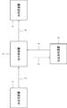
図1は、本発明の第1の実施形態における光通信システムの構成例である。図1に示すように、光通信システムは、波長多重光信号を送信する光送信装置1と、当該波長多重光信号を伝送する伝送路2と、当該波長多重光信号を合波及び分岐する光中継装置3とを含む。また、光通信システムは、波長多重光信号を受信する光受信装置4と、当該波長多重光信号を送受信する光送受信装置5とを含む。
FIG. 1 is a configuration example of an optical communication system according to the first embodiment of the present invention. As shown in FIG. 1, the optical communication system includes an
図2は、光送信装置1の構成例を示す図である。光送信装置1は、複数の送信部11−1乃至11−N(特に区別する必要が無い場合、「送信部11」と記載する)と、処理部12と、制御部13とを備える。
FIG. 2 is a diagram illustrating a configuration example of the
複数の送信部11−1〜11−Nの各々は、互いに、異なる波長の光信号を送信する。送信部11が送信する光信号は、例えば位相変調により、情報(データ)を含めることができる。複数の送信部11−1〜11−Nが出力する複数の光信号のうちの少なくとも1つがデータ用の光信号として用いられる。
Each of the plurality of transmission units 11-1 to 11-N transmits optical signals having different wavelengths. The optical signal transmitted by the
データ用の光信号として用いられる波長は、顧客のニーズや障害の発生などに応じて変更される。複数の顧客が存在する場合、当該複数の顧客の各々に対して少なくとも1つの波長が、情報(データ)を伝送するための光信号の波長として割り当てられている。この場合において、第1の顧客に割り当てられた波長は、当該第1の顧客のニーズに応じて、他の波長(例えば、使用されていない波長)へと変更することができる。また、第1の顧客に割り当てられた波長と、第2の顧客に割り当てられた波長とを入れ替えることもできる。また、第1の顧客に割り当てられた波長は、当該波長を出力している送信部11に障害が発生したことに応じて、他の波長(障害が発生していない他の送信部11が送信する波長)へと変更することができる。
The wavelength used as an optical signal for data is changed according to customer needs or occurrence of a failure. When there are a plurality of customers, at least one wavelength is assigned to each of the plurality of customers as a wavelength of an optical signal for transmitting information (data). In this case, the wavelength assigned to the first customer can be changed to another wavelength (for example, an unused wavelength) according to the needs of the first customer. Also, the wavelength assigned to the first customer and the wavelength assigned to the second customer can be interchanged. In addition, the wavelength assigned to the first customer is transmitted to another wavelength (the
処理部12は、制御部13からの指示に応じて、複数の送信部11から出力される複数の光信号のうち所定の波長の光信号を選択し、制御情報のビットパターンに対応するように、当該選択した光信号を強度変調する。なお、制御情報は、伝送ネットワーク上の他の装置を制御するための信号であり、例えば光中継装置3や光受信装置4に対して、光信号のチャネルの変更を指示する信号である。そして、処理部12は、当該選択した光信号を強度変調した後に、当該複数の光信号を合波して波長多重光信号として出力する。
In response to an instruction from the
処理部12は、例えば、特許第4748514号公報に記載の波長選択スイッチを用いることができる。当該波長選択スイッチは、入力された複数の光波から、所望の波長の光波をドロップすることができる。また、当該波長選択スイッチは、入力された複数の光波に対して、所望の波長の光波をアドすることができ、入力された複数の光波とアドした光波とを合波して、波長多重光信号として出力することができる。また、当該波長選択スイッチは、基板上に形成された光導波回路と当該光導波回路に熱変動を加えて光進行経路の切り替え制御を行う制御手段を有し、ドロップする光波の波長やアドする光波の波長を的確に制御することができる。
For example, the wavelength selective switch described in Japanese Patent No. 4748514 can be used as the
当該波長選択スイッチが、複数の送信部11が出力する複数の光信号のうち所定の波長の光信号を選択し、制御情報のビットパターンに従ってドロップする(又はドロップしない)ことにより、当該所定の波長の光信号を制御信号光として用いることができる。当該波長選択スイッチは、複数の送信部11が出力する複数の光信号のうち所定の波長の光信号を、制御情報のビットが「0」の場合(制御情報のビットが「0」の間)はドロップし、当該ビットが「1」の場合(制御情報のビットが「1」の間)はドロップしない。すなわち、制御情報のビットが「1」の場合だけ、当該所定の波長の光信号が存在することになる。したがって、当該波長多重光信号を受信する装置は、当該波長多重光信号に含まれる所定の波長を検出することにより、制御情報のビットパターンを復号することができる。
The wavelength selection switch selects an optical signal having a predetermined wavelength from the plurality of optical signals output from the plurality of
制御部13は、当該処理部12が所定の波長の光信号に対して強度変調をかけるように制御する。具体的には、制御部13は、処理部12に対して、複数の送信部11が出力する複数の光信号のうち、制御信号光として用いる所定の波長を通知する。そして、制御部13は、当該波長多重光信号を受信する装置(例えば、光中継装置3)を制御するための制御情報のビットパターンに対応するように、制御信号光として用いる所定の波長の光信号の一部をドロップする旨を、処理部12に対して指示する。制御部13は、処理部12に対して、制御情報のビットパターンが「0」であることに応じて、当該所定の波長の光信号をドロップする旨を指示する。一方、制御情報のビットパターンが「1」の場合は、制御部13は、当該所定の波長の光信号をドロップする旨は指示しない。
The
ここで、制御信号光として用いる所定の波長の光信号は、送信部11が出力する光信号のうち、データ用の光信号として用いていない光信号である。制御部13は、外部の制御装置(図示していない)からの制御信号に基づいて、制御信号光用の波長を決定する。当該外部の制御装置は、例えば、データ用の光信号として用いられている波長を制御部13に通知する。制御部13は、当該通知に基づいて、データ用として用いていない波長のうちの少なくとも1つを、制御信号光用の波長として決定する。
Here, the optical signal of a predetermined wavelength used as the control signal light is an optical signal that is not used as an optical signal for data among the optical signals output from the
上記の通り、処理部12は、波長多重光信号から任意の波長を選択できる機能を有するので、当該制御信号光用の波長が変化しても、当該変化に応じて制御信号光として用いる波長を変更できる。したがって、第1の実施形態における光送信装置1は、データ用の光信号の波長が顧客のニーズや障害の発生などのネットワークの状況に応じて変更され、それに伴って制御信号光の波長を変更する必要が生じたとしても、当該変更に柔軟に対応することができる。
As described above, since the
図3は、本発明の第1の実施形態における、光送信装置1の動作例を示すフローチャートである。図3において、複数の送信部11−1〜11−Nの各々は、互いに異なる波長の光信号を送信する(S101)。
FIG. 3 is a flowchart showing an operation example of the
制御部13は、処理部12に対して、制御信号光として用いる所定の波長を指定するとともに、制御情報のビットパターンに対応するように、当該所定の波長の光信号に対して強度変調をかけるように制御する(S102)。具体的には、制御部13は、処理部12に対して、制御情報のビットパターンが「0」であることに応じて、当該所定の波長の光信号をドロップする旨を指示する。
The
処理部12は、制御部13からの指示に応じて、複数の送信部11から出力される複数の光信号のうち所定の波長の光信号を選択し、制御情報のビットパターンに対応するように、当該選択した光信号を強度変調する(S103)。
In response to an instruction from the
処理部12は、当該選択した光信号を強度変調した後に、当該複数の光信号を合波して波長多重光信号として出力する(S104)。
After the intensity of the selected optical signal is modulated, the
上記の通り、光送信装置1は、処理部12を用いることにより、複数の送信部11から出力される複数の光信号のうち所定の波長を選択して、制御情報のビットパターンに対応するようにドロップする(又はドロップしない)。したがって、当該光送信装置1は、データ用の光信号の波長が顧客のニーズや障害の発生などのネットワークの状況に応じて変更され、それに伴って制御信号光の波長を変更する必要が生じたとしても、当該変更に柔軟に対応できる。
As described above, the
<第2の実施形態>
第2の実施形態の概要について、図面を参照して説明する。第2の実施形態における光通信システムの構成例は、図1と同様である。図4は、光中継装置3の構成例を示す図である。光中継装置3は、光受信部30と、処理部32と、制御部33とを備える。<Second Embodiment>
The outline of the second embodiment will be described with reference to the drawings. The configuration example of the optical communication system in the second embodiment is the same as that in FIG. FIG. 4 is a diagram illustrating a configuration example of the
光受信部30は、光送信装置1から送信された波長多重光信号を、伝送路2を介して受信し、それを処理部32へ出力する。なお、光受信部30は光分岐部であってもよい。この場合において、光分岐部は、伝送路2から入力された波長多重光信号を分岐し、一方の波長多重光信号を処理部32に出力し、他方の波長多重信号を他の外部装置(例えば、光送受信装置5)に出力する。他方の波長多重光信号は、光中継装置3に含まれる他のデバイス(図示していない)において所定の処理を施された後、光送受信装置5に出力される。なお、他方の波長多重光信号は、所定の処理を施す必要がない場合は、そのまま他の光送受信装置5に出力される。
The
処理部32は、制御部33からの指示に応じて、波長多重光信号に含まれる所定の波長の光信号を選択し、通知情報のビットパターンに対応するように、当該選択した光信号の光パワーをフィルタする。処理部32は、通知情報のビットパターンに従って強度変調した当該所定の波長の光信号を含む波長多重光信号を、伝送路2に出力する。
In response to an instruction from the
上記の処理部32は、波長多重光信号に含まれる所定の波長の光パワーをフィルタして出力する機能を有する。処理部32は、波長多重光信号に含まれる所定の波長の光信号を、通知情報のビットパターンに従ってドロップする(又はドロップしない)ことにより、当該所定の波長の光信号を制御信号光として用いる。具体的には、処理部32は、所定の波長の光信号について、通知情報のビットが「0」の場合(通知情報のビットが「0」の間)はドロップし、当該ビットが「1」の場合(通知情報のビットが「1」の間)はドロップしない。なお、光中継装置3が送信する制御信号光は、自装置の状態(例えば、故障状況など)を、光受信装置4に通知するための信号である。
The
第1の実施形態と同様、処理部32は、例えば、特許第4748514号公報に記載の波長選択スイッチを用いることができる。当該波長選択スイッチは、入力された波長多重光信号を互いに異なる波長の複数の光波に分波し、当該分波した複数の光波のうち所望の波長の光波をドロップすることができる。また、当該波長選択スイッチは、当該分波した複数の光波に対して、所望の波長の光波をアドすることができ、当該分波した複数の光波と当該アドした光波とを合波して、波長多重光信号として出力することができる。処理部32は、通知情報のビットパターンに従って一部分をドロップした所定の波長の光信号を含む波長多重光信号を、伝送路2を介して自装置の状態を通知する装置(例えば、光受信装置4)に送信する。
As in the first embodiment, the
制御部33は、自装置の状況(例えば、故障状況など)を通知するための通知情報を生成する。制御部33は、当該通知情報を生成するために、光中継装置3に含まれるデバイスから、故障状況等を収集する。
The
また、制御部33は、光受信部30において受信される波長多重光信号のうち所定の波長の光信号に対して強度変調をかけるように、処理部32を制御する。具体的には、制御部33は、波長多重光信号に含まれる複数の波長のうち、制御信号光として用いる所定の波長を決定する。そして、制御部33は、生成した通知情報のビットパターンに対応するように、当該所定の波長の光信号の一部をドロップする旨を、処理部32に対して指示する。制御部33は、処理部32に対して、通知情報のビットパターンが「0」であることに応じて、当該所定の波長の光信号をドロップする旨を指示する。なお、通知情報のビットパターンが「1」の場合は、制御部33は、当該所定の波長の光信号をドロップする旨は指示しない。
The
ここで、第1の実施形態の制御情報と同様に、通知情報として用いる所定の波長の光信号は、データ用の光信号として用いていない光信号である。制御部33は、外部の制御装置(図示していない)からの制御信号に基づいて、制御信号光用の波長を決定する。当該制御信号は、データ用の光信号として用いていない光信号のうちの少なくとも1つを、制御部33に通知するための信号である。
Here, similarly to the control information of the first embodiment, the optical signal having a predetermined wavelength used as the notification information is an optical signal that is not used as an optical signal for data. The
図5は、第2の実施形態における光中継装置3の動作例を示すフローチャートである。図5において、光受信部30が、伝送路2から入力した波長多重光信号を受信する(S201)。
FIG. 5 is a flowchart showing an operation example of the
制御部33は、処理部32に対して、制御信号光として用いる所定の波長を指定するとともに、通知情報のビットパターンに対応するように、当該指定した所定の波長の光信号に対して強度変調をかけるように指示する(S202)。具体的には、制御部33は、処理部32に対して、通知情報のビットパターンが「0」であることに応じて、当該所定の波長の光信号をドロップする旨を指示する。
The
処理部32は、制御部33からの指示に応じて、波長多重光信号に含まれる所定の波長の光信号を選択し、通知情報のビットパターンに対応するように、当該選択した光信号の光パワーをフィルタする(S203)。
In response to an instruction from the
処理部32は、通知情報のビットパターンに従って、強度変調した当該所定の波長の光信号を含む波長多重光信号を、伝送路2に出力する(S204)。
The
上記の通り、光中継装置3は、処理部32を用いて、波長多重光信号から選択した波長の光信号を、通知情報のビットパターンに基づきフィルタすることにより、当該通知情報に対応した光信号(制御信号光)を波長多重光信号に含める。したがって、当該光中継装置3は、制御信号光用の光源を備えることなく、当該制御信号光を出力することができる。
As described above, the
また、光中継装置3の処理部32は、波長多重光信号から所定の波長を選択して上記処理を実行できるので、顧客のニーズや障害の発生などネットワークの環境に応じて制御信号光の波長を変更する必要が生じたとしても、当該変更に柔軟に対応できる。
Further, since the
<第3の実施形態>
第3の実施形態の概要について、図面を参照して説明する。なお、第3の実施形態において、第1の実施形態及び第2の実施形態と同様の構成については、説明を省略する。<Third Embodiment>
The outline of the third embodiment will be described with reference to the drawings. Note that in the third embodiment, a description of the same configurations as those of the first embodiment and the second embodiment is omitted.
第3の実施形態における光通信システムの構成例は、図1と同様である。図6は、光送信装置1の構成例を示す図である。光送信装置1は、複数の送信部11−1乃至11−Nと、処理部12と、制御部13と、光出力部14とを備える。
The configuration example of the optical communication system in the third embodiment is the same as that in FIG. FIG. 6 is a diagram illustrating a configuration example of the
光出力部14は、処理部12から出力される波長多重光信号の強度を一定にする目的で、当該波長多重光信号の強度の変化を補償するためのダミー光を出力する。光出力部14は、制御部13からの要求に応じて、所定の強度のダミー光を出力する。光出力部14は、例えば、ASE(Amplified Spontaneous Emission)光源を適用することができる。
The
光出力部14が出力するダミー光の波長は、送信部11−1〜11−Nが出力する複数の光信号の波長以外の波長である。すなわち、光出力部14は、データ用の光信号の波長帯とは異なる波長帯のダミー光を出力する。
The wavelength of the dummy light output from the
制御部13は、処理部12に対して、制御情報のビットが「0」であることに応じて、当該所定の波長の光信号をドロップする旨を指示する。この場合において、制御部13は、ドロップした所定の波長の光信号を補償するように、光出力部14にダミー光を出力する旨を要求する。具体的には、制御部13は、当該所定の波長の光信号をドロップした場合に、光出力部14に対して、ドロップした当該所定の波長の光信号の強度と同じ強度のダミー光を出力する旨を要求する。
The
なお、光出力部14が、処理部12から出力される波長多重光信号の強度をモニタして、当該波長多重光信号の強度が一定になるように、出力するダミー光の強度を調整してもよい。
The
処理部12は、複数の送信部11が出力する複数の光信号に所望の波長の光波をアドすることができるので、当該複数の光信号に光出力部14から入力したダミー光をアドする。
Since the
図7は、光送信装置1から出力された波長多重光信号を受信する、光中継装置3の構成例である。図7に示すように、光中継装置3は、光分岐部31と、制御部33と、フィルタ部34とを含む。なお、図7は、光中継装置3において、波長多重光信号に含まれる制御信号光を抽出(検出)するための機能を提供する構成例を示すものであり、他の構成が含まれることを除外するものではない。
FIG. 7 is a configuration example of the
光分岐部31は、入力される波長多重光信号を分岐し、一方の波長多重光信号をフィルタ部34へ、他方の波長多重光信号を他の外部装置(例えば、光受信装置4)に出力する。
The optical branching
フィルタ部34は、波長多重光信号に含まれる複数の光信号のうち、制御信号光用の波長の光信号だけを透過して制御部33に出力し、他の波長の光信号を破棄する。フィルタ部34は、制御信号光の波長を指定する制御信号を受信し、当該受信した制御信号が指定する波長の光信号(すなわち、制御信号光)だけを透過する。
The
制御部33は、フィルタ部34から入力された制御信号光に基づいて、制御情報のビットパターンを復号し、当該制御情報に基づいて光中継装置3内のデバイス(例えば、光スイッチ、光リレーなど)を制御する。制御部33は、例えば、制御情報に基づいて、光スイッチや光リレーに対して光路の変更を要求する。
The
図8は、光送信装置1から出力された波長多重光信号を受信する、光中継装置3の動作例を示すフローチャートである。図8において、光分岐部31は、入力される波長多重光信号を分岐し、一方の波長多重光信号をフィルタ部34へ、他方の波長多重光信号を他の外部装置(例えば、光受信装置4)に出力する(S301)。
FIG. 8 is a flowchart showing an operation example of the
フィルタ部34は、波長多重光信号に含まれる複数の光信号のうち、制御信号光用の波長の光信号だけを透過して制御部33に出力し、他の波長の光信号を破棄する(S302)。
The
制御部33は、フィルタ部34から入力した制御信号光に基づいて、制御情報のビットパターンを復号し、当該制御情報に基づいて光中継装置3内のデバイスを制御する(S303)。
The
図9は、光送信装置1から出力された波長多重光信号を光中継装置3を介して受信する、光受信装置4の構成例を示す図である。図9に示すように、光受信装置4は、光分岐部41と、光分波部42と、受信部43−1〜43−Nと、フィルタ部44と、制御部45とを含む。
FIG. 9 is a diagram illustrating a configuration example of the
光分岐部41は、入力された波長多重光信号を分岐し、一方の波長多重光信号を光分波部42に出力し、他方の波長多重光信号をフィルタ部44に出力する。
The optical branching
光分波部42は、入力された波長多重光信号を分波し、分波した複数の光信号を、制御部45からの要求に応じて、受信部43−1〜43−Nの各々に割り当てられた波長に基づいて受信部43−1〜43−Nの各々に出力する。
The
受信部43−1〜43−Nの各々は、割り当てられた波長の光信号を受信する。 Each of the reception units 43-1 to 43-N receives an optical signal having an assigned wavelength.
フィルタ部44は、入力された波長多重光信号に含まれる複数の光信号のうち、制御信号光用の波長の光信号だけを透過して制御部45に出力し、他の波長の光信号を破棄する。フィルタ部44は、制御信号光の波長を指定する制御信号を例えば外部の制御装置から受信し、当該受信した制御信号が指定する波長の光信号(すなわち、制御信号光)だけを透過する。
The
制御部45は、フィルタ部44から入力された制御信号光に基づいて、制御情報のビットパターンを復号し、当該制御情報に基づいて、光受信装置4内のデバイスを制御する。制御部45は、例えば光分波部42に対して、制御情報に基づいてチャネルの変更(複数の受信部43の各々に割り当てられた波長の変更)を要求する。
The
図10は、光送信装置1から出力された波長多重光信号を光中継装置3を介して受信する、光受信装置4の動作例を示すフローチャートである。なお、図10は、制御部45が光分波部42に対してチャネルの変更(複数の受信部43の各々に割り当てられた波長の変更)を要求する場合の動作例である。
FIG. 10 is a flowchart illustrating an operation example of the
光分岐部41は、入力された波長多重光信号を分岐し、一方の波長多重光信号を光分波部42に出力し、他方の波長多重光信号をフィルタ部44に出力する(S401)。
The optical branching
フィルタ部44は、入力された波長多重光信号に含まれる複数の光信号のうち、制御信号光用の波長の光信号だけを透過して制御部45に出力し、他の波長の光信号を破棄する(S402)。
The
制御部45は、フィルタ部44から入力された制御信号光に基づいて、制御情報のビットパターンを復号する(S403)。制御部45は、光分波部42に対して、復号した制御情報に基づいてチャネルの変更(複数の受信部43の各々に割り当てられた波長の変更)を要求する(S404)。
The
光分波部42は、入力された波長多重光信号を分波し、制御部45からの要求に応じて変更された割り当てに基づいて、分波した各光信号を複数の受信部43の各々に出力する(S405)。
The
受信部43−1〜43−Nの各々は、割り当てられた波長の光信号を受信する(S406)。 Each of the receiving units 43-1 to 43-N receives an optical signal having an assigned wavelength (S406).
図11は、光送信装置1から出力された波長多重光信号を受信する、光中継装置3の他の構成例を示す図である。光中継装置3は、光分岐部31と、制御部33と、受信部35と、局発光出力部36とを含む。
FIG. 11 is a diagram illustrating another configuration example of the
受信部35は、入力された波長多重光信号と、局発光出力部36から入力された所定の波長の局発光とを干渉させ、波長多重光信号から所定の波長を選択的に受信する。受信部35は、選択的に受信された所定の波長の光信号を、制御部33に出力する。
The receiving
受信部35は、例えば、コヒーレント検波を行うコヒーレント検波部である。コヒーレント検波部は、光分岐部31から入力された波長多重信号と、局発光出力部36から入力された所定の波長の局発光とが干渉した信号を、制御部33に出力する。コヒーレント検波部は、コヒーレントミキサーと呼ばれる90度ハイブリッドミキサー(図示していない)を備える。当該コヒーレントミキサーは、光分岐部31から入力された波長多重信号と、局発光出力部36から入力された所定の波長の局発光とが干渉した信号(干渉信号)を出力する。
The receiving
局発光出力部36は、受信した制御信号に基づいて、所定の波長の局発光を出力する。当該制御信号は、局発光出力部36が出力する局発光の波長を指定する信号であり、指定する波長は制御信号光用の波長である。当該制御信号は、例えば、光送信装置1や外部の制御装置(図示していない)から通知される。なお、制御信号は、例えば伝送路2とは異なる回線により提供される通信路(アウトバウンド通信路)を用いて、光中継装置3へ通知されることができる。
The local
また、制御信号は、制御信号光に含まれていてもよい。この場合において、制御信号は、所定の時間経過後における局発光の波長を指定する信号となる。例えば、所定の時間経過後に制御信号光の波長を変更することが予定されている場合、光送信装置1は、当該所定の時間経過後に局発光の波長を変更させるべく、予め制御信号を制御信号光に含めて光中継装置3へ送信しておく。光中継装置3は、制御信号によって指定された所定の時間経過後に、局発光の波長を当該制御信号によって指定された波長へ変更する。このようにして、制御信号光に制御信号が含まれていた場合でも、制御信号が所定の時間経過後における波長を指定することによって、当該制御信号光の波長の変更に対応することができる。
The control signal may be included in the control signal light. In this case, the control signal is a signal that specifies the wavelength of local light emission after a predetermined time has elapsed. For example, when it is scheduled to change the wavelength of the control signal light after a lapse of a predetermined time, the
上述したように、受信部35は、入力された波長多重光信号と所定の波長の局発光とを干渉させ、波長多重光信号から所定の波長を選択的に受信する。そのため、局発光出力部36が出力する局発光を制御信号光用の波長とすることにより、受信部35は、当該波長多重光信号に含まれる複数の光信号から制御信号光だけを選択的に受信し、当該制御信号光を制御部33に出力することができる。
As described above, the receiving
また、図12は、光送信装置1から出力された波長多重光信号を光中継装置3を介して受信する、光受信装置4の他の構成例である。光受信装置4は、光分岐部41と、光分波部42と、受信部43−1〜43−Nと、制御部45と、受信部46と、局発光出力部47とを備える。
FIG. 12 shows another configuration example of the
受信部46は、入力された波長多重光信号と、局発光出力部47から入力された所定の波長の局発光とを干渉させ、波長多重光信号から所定の波長を選択的に受信する。受信部46は、選択的に受信した所定の波長の光信号を、制御部45に出力する。なお、受信部46は、上述した光中継装置3の受信部35と同様に、例えばコヒーレント検波を行うコヒーレント検波部である。コヒーレント検波部は、光分岐部41から入力された波長多重信号と、局発光出力部47から入力された所定の波長の局発光とが干渉した信号を、制御部45に出力する。
The receiving
局発光出力部47は、受信した制御信号に基づいて、所定の波長の局発光を出力する。当該制御信号は、局発光出力部47が出力する所定の波長の局発光を指定する信号であり、当該所定の波長は制御信号光用の波長である。当該制御信号は、例えば、光送信装置1や外部の制御装置(図示していない)から通知される。なお、制御信号は、例えば伝送路2とは異なる回線により提供される通信路(アウトバウンド通信路)を用いて、光受信装置4へ通知されることができる。
The local
上述したように、受信部46は、入力された波長多重光信号と所定の波長の局発光とを干渉させ、波長多重光信号から所定の波長を選択的に受信する。そのため、局発光出力部47が出力する局発光を制御信号光用の波長とすることにより、受信部46は、当該波長多重光信号に含まれる複数の光信号から制御信号光だけを受信し、制御信号光を制御部45に出力することができる。
As described above, the receiving
<第4の実施形態>
第4の実施形態の概要について、図面を参照して説明する。なお、第4の実施形態において、第1乃至第3の実施形態と同様の構成については、説明を省略する。<Fourth Embodiment>
The outline of the fourth embodiment will be described with reference to the drawings. Note that in the fourth embodiment, a description of the same configurations as those of the first to third embodiments is omitted.
第4の実施形態は、光中継装置3が処理部32を用いてドロップした波長の光信号をダミー光で補償する光出力部を備え、当該光中継装置3から出力される波長多重光信号の強度を一定に保つものである。
The fourth embodiment includes an optical output unit that compensates for an optical signal having a wavelength dropped by the
図13は、光中継装置3の構成例を示す図である。光中継装置3は、光受信部30と、処理部32と、制御部33と、光出力部39とを備える。
FIG. 13 is a diagram illustrating a configuration example of the
光出力部39は、例えば、ASE光源である。光出力部39は、処理部32から出力される波長多重光信号の強度を一定にする目的で、当該波長多重光信号の強度の変化を補償するためのダミー光を出力する。光出力部39は、制御部33からの要求に応じて、所定の強度のダミー光を出力する。
The
光出力部39が出力するダミー光の波長は、波長多重光信号において、データが重畳されている複数の光信号の波長以外の波長である。すなわち、光出力部39は、データ用の光信号の波長帯とは異なる波長帯のダミー光を出力する。
The wavelength of the dummy light output from the
制御部33は、処理部32に対して、通知情報のビットが「0」であることに応じて、所定の波長の光信号をドロップする旨を指示する。この場合において、制御部33は、ドロップした所定の波長の光信号を補償するように、光出力部39にダミー光を出力する旨を要求する。具体的には、制御部33は、所定の波長の光信号をドロップした場合に、光出力部39に対して、ドロップした所定の波長の光信号の強度と同じ強度のダミー光を出力する旨を要求する。
The
なお、光出力部39が、処理部32から出力される波長多重光信号の強度をモニタして、当該波長多重光信号の強度が一定になるように、出力するダミー光の強度を調整してもよい。
The
処理部32は、制御部33からの指示に応じて、入力された波長多重光信号から所定の波長の光信号をドロップし、当該ドロップした波長多重光信号に光出力部39から入力したダミー光をアドする。
In response to an instruction from the
上記の通り、光中継装置3は光出力部39を備え、処理部32を用いてドロップした波長の光信号をダミー光で補償することにより、光中継装置3から出力される波長多重光信号の強度を一定に保つことができる。
As described above, the
<第5の実施形態>
第5の実施形態の概要について、図面を参照して説明する。なお、第5の実施形態において、第1乃至第4の実施形態と同様の構成については、説明を省略する。<Fifth Embodiment>
The outline of the fifth embodiment will be described with reference to the drawings. Note that in the fifth embodiment, description of the same configuration as in the first to fourth embodiments is omitted.
第5の実施形態は、光中継装置3が、2つの異なる光受信装置(例えば、図1における光受信装置4及び光送受信装置5)に対して、自装置の状態を通知するための制御信号光を送信するものである。
In the fifth embodiment, the
図14は、光中継装置3の構成例を示す図である。第5の実施形態における光中継装置3は、光受信部30と、光分岐部31と、第1の処理部32−1と、第2の処理部32−2と、制御部33とを備える。
FIG. 14 is a diagram illustrating a configuration example of the
光分岐部31は、光受信部30から入力された波長多重光信号を分岐し、第1の処理部32−1と第2の処理部32−2とに出力する。
The optical branching
第1の処理部32−1は、第1の光受信装置宛の波長多重光信号について、当該波長多重光信号に含まれる第1の所定の波長の光信号の一部分を、通知情報のビットパターンに応じてフィルタ(ドロップ)して、第1の光受信装置に出力する。なお、第1の所定の波長は、光中継装置3と第1の光受信装置との間において、データ用の光信号の波長として用いていない波長から選択される。
For the wavelength multiplexed optical signal addressed to the first optical receiver, the first processing unit 32-1 uses a part of the optical signal having the first predetermined wavelength included in the wavelength multiplexed optical signal as a bit pattern of notification information. Is filtered (dropped) in response to the signal and output to the first optical receiver. The first predetermined wavelength is selected from wavelengths not used as the wavelength of the optical signal for data between the
一方、第2の処理部32−2は、第2の光受信装置宛の波長多重光信号について、当該波長多重光信号に含まれる第2の所定の波長の光信号の一部分を、通知情報のビットパターンに従ってフィルタ(ドロップ)して、第2の光受信装置に出力する。なお、第2の所定の波長は、光中継装置3と第2の光受信装置との間において、データ用の光信号として用いていない波長から選択される。
On the other hand, the second processing unit 32-2 converts a part of the optical signal having the second predetermined wavelength included in the wavelength-multiplexed optical signal to the notification information for the wavelength-multiplexed optical signal addressed to the second optical receiver. Filter (drop) according to the bit pattern and output to the second optical receiver. The second predetermined wavelength is selected from wavelengths not used as data optical signals between the
制御部33は、第1の処理部32−1に対して、制御信号光として用いる第1の所定の波長を指定するとともに、第1の通知情報のビットパターンに対応するように、当該第1の所定の波長の光信号をフィルタする旨を指示する。なお、第1の通知情報は、第1の光受信装置に対して、光中継装置3の状態を通知するための情報である。
The
一方、制御部33は、第2の処理部32−2に対して、制御信号光として用いる第2の所定の波長を指定するとともに、第2の通知情報のビットパターンに対応するように、当該第2の波長の光信号をフィルタする旨を指示する。なお、第2の通知情報は、第2の光受信装置に対して、光中継装置3の状態を通知するための情報である。
On the other hand, the
上記の通り、第5の実施形態において、光中継装置3は、2つの処理部32−1、32−2を備え、当該2つの処理部32−1、32−2がそれぞれ2つの異なる光受信装置(例えば、図1における光受信装置4及び光送受信装置5)に対して、制御信号光を含む波長多重光信号を送信する。したがって、当該光中継装置3は、2つの異なる光受信装置に対して、自装置の状態を通知することができる。
As described above, in the fifth embodiment, the
なお、光中継装置3が備える処理部32は、2つに限られず、いくつであってもよい。この場合、光中継装置3は、処理部32の数に応じた数の光受信装置に対して、制御信号光を含む波長多重光信号を送信でき、自装置の状態を通知することができる。
Note that the number of
<第6の実施形態>
第6の実施形態の概要について、図面を参照して説明する。なお、第6の実施形態において、第1乃至第5の各実施形態と同様の構成については、説明を省略する。<Sixth Embodiment>
The outline of the sixth embodiment will be described with reference to the drawings. Note that in the sixth embodiment, a description of the same configurations as those of the first to fifth embodiments is omitted.
第6の実施形態において、光送信装置1が出力する波長多重光信号には、少なくとも1つの第1の制御信号光が含まれており、光中継装置3が出力する波長多重光信号には、少なくとも1つの第2の制御信号光が含まれている。第1の制御信号光は、光中継装置3に対する制御情報を含む。一方、第2の制御信号光は、光中継装置3が自装置の状態(例えば、故障状況など)を、光受信装置4や光送受信装置5に通知する通知情報を含む。
In the sixth embodiment, the wavelength multiplexed optical signal output from the
第6の実施形態における光通信システムの構成例は、図1と同様である。図15は、第6の実施形態における、光中継装置3の構成例を示す図である。第6の実施形態における光中継装置3は、第1の光分岐部31−1と、第2の光分岐部31−2と、処理部32と、制御部33と、フィルタ部34とを含む。
The configuration example of the optical communication system in the sixth embodiment is the same as that shown in FIG. FIG. 15 is a diagram illustrating a configuration example of the
第1の光分岐部31−1は、伝送路2を介して光送信装置1から入力された波長多重光信号を分岐し、一方の波長多重光信号を第2の光分岐部31−2に出力し、他方の波長多重信号を他の外部装置(例えば、光送受信装置5)に出力する。
The first optical branching unit 31-1 branches the wavelength multiplexed optical signal input from the
第2の光分岐部31−2は、入力された波長多重光信号を分岐し、一方の波長多重光信号を処理部32に出力し、他方の波長多重光信号をフィルタ部34に出力する。
The second optical branching unit 31-2 branches the input wavelength multiplexed optical signal, outputs one wavelength multiplexed optical signal to the
フィルタ部34は、第1の制御信号光の波長を指定する制御信号を受信する。フィルタ部34は、入力された波長多重光信号に含まれる複数の光信号のうち、当該受信した制御信号が指定する波長の光信号(すなわち、第1の制御信号光)だけを透過して制御部33に出力する。
The
制御部33は、自装置の状況(例えば、故障状況など)を通知するための通知情報を生成する。制御部33は、通知情報を生成するために、光中継装置3に含まれるデバイスから、故障状況等を収集する。光中継装置3が自装置の状況を通知するための第2の制御信号光の波長は、フィルタ部34から入力された第1の制御信号光によって光送信装置1から通知される。したがって、制御部33は、第1の制御信号光に基づいて、第2の制御信号光の波長を決定する。
The
制御部33は、生成した通知情報のビットパターンに対応するように、所定の波長である第2の制御信号光の一部分の光パワーをフィルタする旨を、処理部32に対して指示する。なお、第1乃至第3の各実施形態と同様に、第2の制御信号光として用いる所定の波長の光信号は、データ用の光信号として用いていない光信号である。
The
処理部32は、制御部33からの指示に応じて、第2の光分岐部31−2から入力された波長多重光信号のうち、所定の波長の光信号を選択し、通知情報のビットパターンに対応するように、当該選択した光信号の光パワーをフィルタする。具体的には、処理部32は、当該選択した光信号の出力をON/OFF(ドロップしない/ドロップする)する。そして、処理部32は、通知情報のビットパターンに対応するようにドロップした(又はドロップしなかった)所定の波長の光信号(すなわち、第2の制御信号光)を含む波長多重光信号を、伝送路2に出力する。
In response to an instruction from the
図16は、本発明の第6の実施形態における、光中継装置3の動作例を示すフローチャートである。図16において、第1の光分岐部31−1は、伝送路2から入力された波長多重光信号を分岐し、一方の波長多重光信号を第2の光分岐部31−2に出力し、他方の波長多重信号を他の外部装置(例えば、光送受信装置5)に出力する(S501)。
FIG. 16 is a flowchart showing an operation example of the
第2の光分岐部31−2は、入力された波長多重光信号を分岐し、一方の波長多重光信号を処理部32に出力し、他方の波長多重光信号をフィルタ部34に出力する(S502)。
The second optical branching unit 31-2 branches the input wavelength multiplexed optical signal, outputs one wavelength multiplexed optical signal to the
フィルタ部34は、第1の制御信号光の波長を指定する制御信号を受信する。そして、フィルタ部34は、波長多重光信号に含まれる複数の光信号のうち、当該受信した制御信号が指定する波長の光信号(すなわち、第1の制御信号光)だけを透過して制御部33に出力する(S503)。
The
制御部33は、入力された第1の制御信号光のビットパターンを復号し、復号した制御情報に基づいて、波長多重光信号に含まれる複数の光信号の波長のうち、第2の制御信号光として用いる所定の波長を決定する(S504)。
The
制御部33は、自装置の状況(例えば、故障状況など)を通知するための通知情報を生成し、生成した通知情報のビットパターンに対応するように、決定した所定の波長の光パワーをフィルタする旨を、処理部32に対して指示する(S505)。
The
処理部32は、通知情報のビットパターンに従って一部分をフィルタした(ドロップした)所定の波長の光信号(第2の制御信号光)を含む波長多重光信号を、伝送路2に出力する(S506)。
The
図17は、第6の実施形態における、光中継装置3の他の構成例を示す図である。図17に示すように、光中継装置3は、第1の光分岐部31−1と、第2の光分岐部31−2と、処理部32と、制御部33と、受信部35と、局発光出力部36とを含む。
FIG. 17 is a diagram illustrating another configuration example of the
受信部35は、入力された波長多重光信号と、局発光出力部36から入力された所定の波長の局発光とを干渉させ、波長多重光信号から所定の波長を選択的に受信する。受信部35は、選択的に受信した所定の波長の光信号を、制御部33に出力する。そのため、局発光出力部36が出力する局発光を第1の制御信号光の波長とすることにより、受信部35は、当該波長多重光信号に含まれる複数の光信号から制御情報を含む第1の制御信号光だけを受信し、当該第1の制御信号光を制御部33に出力することができる。
The receiving
上記の通り、第6の実施形態における光中継装置3は、光送信装置1からの第1の制御信号光に含まれている制御情報により指定された波長を、通知情報を含む第2の制御信号光の波長とする。したがって、第6の実施形態の光通信システムは、光中継装置3が出力する第2の制御信号光を、光送信装置1が指定することができる。
As described above, the
<第7の実施形態>
第7の実施形態の概要について、図面を参照して説明する。なお、第7の実施形態において、第1乃至第6の各実施形態と同様の構成については、説明を省略する。<Seventh Embodiment>
The outline of the seventh embodiment will be described with reference to the drawings. Note that in the seventh embodiment, a description of the same configurations as those of the first to sixth embodiments is omitted.
図18は、第7の実施形態における光通信システムの構成例を示す図である。第7の実施形態における光通信システムにおいて、光送信装置1が出力する第1の波長多重光信号には、第1の制御信号光が含まれる。第1の制御信号光は、光送信装置1が光中継装置3の制御を行うための第1の制御情報を含む光信号である。
FIG. 18 is a diagram illustrating a configuration example of an optical communication system according to the seventh embodiment. In the optical communication system according to the seventh embodiment, the first wavelength-multiplexed optical signal output from the
また、光中継装置3が出力する第2の波長多重光信号には、第2の制御信号光が含まれる。第2の制御信号光は、光中継装置3が自装置の状況(例えば、故障状況など)を通知するための通知情報を含む光信号である。
The second wavelength multiplexed optical signal output from the
さらに、光送受信装置5が出力する第3の波長多重光信号には、第3の制御信号光が含まれる。第3の制御信号光は、光送受信装置5が光中継装置3の制御を行うための第2の制御情報を含む光信号である。
Further, the third wavelength multiplexed optical signal output from the optical transmitter /
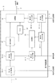
図19は、第7の実施形態における、光中継装置3の構成例を示す図である。光中継装置3は、第1の光分岐部31−1と、第2の光分岐部31−2と、第3の光分岐部31−3と、処理部32と、制御部33と、第1乃至第4のフィルタ部34−1〜34−4とを含む。
FIG. 19 is a diagram illustrating a configuration example of the
第2の光分岐部31−2は、第1の光分岐部31−1から入力された第1の波長多重光信号を分岐し、一方の第1の波長多重光信号を第1のフィルタ部34−1に、他方の第1の波長多重光信号を第3のフィルタ部34−3に出力する。 The second optical branching unit 31-2 branches the first wavelength-division multiplexed optical signal input from the first optical branching unit 31-1, and one of the first wavelength-division multiplexed optical signals is the first filter unit. The other first wavelength multiplexed optical signal is output to the third filter unit 34-3.
第1のフィルタ部34−1は、制御信号に応じて、光送信装置1が出力した第1の波長多重光信号に含まれる第1の制御信号光だけを透過し、制御部33に出力する。
The first filter unit 34-1 transmits only the first control signal light included in the first wavelength-multiplexed optical signal output from the
第3のフィルタ部34−3は、光送信装置1から入力された第1の波長多重光信号に含まれる光信号のうち、光受信装置4宛の光信号だけを透過して処理部32に出力する。
The third filter unit 34-3 transmits only the optical signal addressed to the
第3の光分岐部31−3は、光送受信装置5から入力された第3の波長多重光信号を分岐し、一方の第3の波長多重光信号を第2のフィルタ部34−2に、他方の第3の波長多重光信号を第4のフィルタ部34−4に出力する。
The third optical branching unit 31-3 branches the third wavelength-multiplexed optical signal input from the optical transmission /
第2のフィルタ部34−2は、制御信号に応じて、光送受信装置5から入力された第3の波長多重光信号に含まれる第3の制御信号光だけを透過して制御部33に出力する。
The second filter unit 34-2 transmits only the third control signal light included in the third wavelength-multiplexed optical signal input from the optical transmission /
第4のフィルタ部34−4は、光送受信装置5から入力された第3の波長多重光信号に含まれる光信号のうち、光受信装置4宛の光信号だけを透過して処理部32に出力する。
The fourth filter unit 34-4 transmits only the optical signal addressed to the
制御部33は、入力された第1の制御信号光から第1の制御情報のビットパターンを復号し、当該復号した第1の制御情報に基づいて、光中継装置3内のデバイスを制御する。同様に、制御部33は、入力された第3の制御信号光から第2の制御情報のビットパターンを復号し、当該復号した第2の制御情報に基づいて、光中継装置3内のデバイスを制御する。
The
また、制御部33は、自装置の状況(例えば、故障状況など)を通知するための通知情報を生成する。制御部33は、通知情報を生成するために、光中継装置3に含まれるデバイスから、故障状況等を収集する。
In addition, the
ここで、第7の実施形態では、光中継装置3が自装置の状況を通知するための第2の制御信号光の波長は、第1の制御信号光によって光送信装置1から通知される。したがって、制御部33は、第1の制御信号光から復号した第1の制御情報に基づいて、第2の制御信号光の波長を決定する。なお、第2の制御信号光の波長は、光送受信装置5から通知されてもよい。この場合において、制御部33は、光送受信装置5から受信する第3の波長多重光信号に含まれる第3の制御信号光から復号した第2の制御情報に基づいて、第2の制御信号光の波長を決定する。
Here, in the seventh embodiment, the wavelength of the second control signal light used for the
制御部33は、第1の制御信号光から復号された第1の制御情報に基づいて、第2の制御信号光の波長を決定する。そして、制御部33は、生成した通知情報のビットパターンに対応するように、決定した所定の波長の光信号の一部分をドロップする旨を、処理部32に対して指示する。なお、第1乃至第3の各実施形態と同様に、第2の制御信号光として用いる所定の波長の光信号は、データ用の光信号として用いていない光信号である。
The
処理部32は、第3のフィルタ部34−3から入力された波長多重光信号と、第4のフィルタ部34−4から入力された波長多重光信号と、制御部33からの指示に応じて、一部分が通知情報のビットパターンに基づいてドロップされた所定の波長の第2の制御信号光と、を合波して伝送路2に出力する。
The
上記のとおり、光中継装置3は、光送信装置1からの第1の制御信号光から復号した第1の制御情報だけでなく、光送受信装置5からの第3の制御信号光から復号した第2の制御情報に基づいて、光中継装置3内のデバイスを制御する。したがって、第7の実施形態における光通信システムは、光送信装置1だけでなく光送受信装置5からも、光中継装置3内のデバイスを制御することができる。
As described above, the
<第8の実施形態>
第8の実施形態の概要について、図面を参照して説明する。なお、第8の実施形態において、第1乃至第7の各実施形態と同様の構成については、説明を省略する。<Eighth Embodiment>
The outline of the eighth embodiment will be described with reference to the drawings. Note that in the eighth embodiment, a description of the same configurations as those in the first to seventh embodiments is omitted.
第8の実施形態における光通信システムの構成例は、図1と同様である。図20は、第8の実施形態における、光送信装置1の構成例を示す図である。光送信装置1は、複数の送信部11−1乃至11−Nと、光合波部17と、処理部12と、制御部13と、光出力部14とを備える。また、光送信装置1は、可変光減衰器(Variable Optical Attenuator:VOA)15と、光分波部16とを備える。
The configuration example of the optical communication system in the eighth embodiment is the same as that in FIG. FIG. 20 is a diagram illustrating a configuration example of the
VOA15は、入力される所定の波長の光信号の強度を、制御部13からの要求に応じて変更する。VOA15としては、特許第5065333号公報に記載の可変光減衰器を用いることができる。当該可変光減衰器は、光ファイバ中を伝搬する信号光の強度を任意の光強度に減衰させることができる。可変光減衰器は、出力する光信号の強度を、印加する電圧の大きさにより可変することができる。なお、可変光減衰器は、マイクロ秒単位で、出力する光信号の強度を変化させることができる。
The
VOA15は、所定の波長の光信号について、制御情報のビットが「0」の場合(制御情報のビットが「0」の間)は当該所定の波長の光信号の強度を「0」に減衰する。一方、VOA15は、当該ビットが「1」の場合(制御情報のビットが「1」の間)は当該所定の波長の光信号の強度を減衰しない。すなわち、波長多重光信号に含まれる所定の波長の光信号は、制御情報のビットが「0」の場合は所定の波長の光信号が含まれず(強度が「0」)、当該ビットが「1」の場合は当該所定の波長の光信号が含まれることになる。したがって、当該波長多重光信号を受信する装置(例えば、光中継装置3)は、波長多重光信号に含まれる所定の波長を検出することにより、制御情報のビットパターンを復号することができる。
The
制御部13は、光分波部16に対して、当該波長多重光信号に含まれる複数の波長のうち、制御信号光として用いる所定の波長の光信号を分波して、VOA15に入力することを要求する。
The
また、制御部13は、光中継装置3を制御するための制御情報のビットパターンに対応するように、所定の波長の光信号を減衰する(又は減衰しない)旨を、VOA15に対して指示する。
In addition, the
さらに、制御部13は、VOA15に対して制御信号光として用いる所定の波長の光信号を減衰する旨を指示した場合に、当該所定の波長の光信号の減衰を補償する旨を、光出力部14に要求する。
Further, when the
光分波部16は、制御部13からの要求に応じて、当該制御部13から指定される所定の波長の光信号を分波し、VOA15に入力する。光分波部16は、波長多重光信号に含まれるVOA15に入力した光信号以外の光信号を、処理部12に出力する。
The
処理部12は、光分波部16から入力された光信号に、VOA15から入力された所定の波長の光信号と、光出力部14から入力されたダミー光とをアドして、伝送路2から出力する。
The
上記で説明したVOA15は、光中継装置3にも適用することができる。図21は、第8の実施形態における、光中継装置3の構成例を示す図である。光中継装置3は、第1の光分岐部31−1と、第2の光分岐部31−2と、第3の光分岐部31−3と、処理部32と、制御部33と、第1のフィルタ部34−1と、第2のフィルタ部34−2と、第4のフィルタ部34−4とを備える。また、光中継装置3は、光分波部37と、VOA38とを含む。
The
VOA38は、入力される所定の波長の光信号の強度を、制御部33からの要求に応じて変更する。なお、図20のVOA15と同様に、VOA38としては、特許第5065333号公報に記載の可変光減衰器を用いることができる。
The
制御部33は、光分波部37に対して、波長多重光信号に含まれる複数の波長のうち、制御信号光として用いる所定の波長の光信号を分波し、VOA38に出力することを要求する。
The
また、制御部33は、光中継装置3の状態を通知するための通知情報のビットパターンに対応するように、所定の波長の光信号を減衰する(又は減衰しない)旨を、VOA38に対して指示する。
Further, the
光分波部37は、制御部33からの要求に応じて、当該制御部33から指定される所定の波長の光信号を分波し、VOA38に出力する。光分波部37は、波長多重光信号に含まれるVOA38に入力した光信号以外の光信号を、処理部32に出力する。
In response to a request from the
処理部32は、光分波部37から入力された波長多重光信号と、第4のフィルタ部34−4から入力された波長多重光信号と、VOA38から入力された所定の波長の光信号とを合波し、伝送路2に出力する。
The
上記の通り、第8の実施形態では、出力する光信号の強度が印加する電圧の大きさにより可変であるVOA15又はVOA38を、光送信装置1又は光中継装置3が備える。VOA15又はVOA38は、マイクロ秒単位で、出力する光信号の強度を変化させることができるので、所定の波長の光信号の強度を変化させることが可能となる。したがって、光送信装置1又は光中継装置3は、制御情報又は通知情報のビットパターンが高速に変化した場合であっても、所定の波長の光信号を当該制御情報又は通知情報に対応させることが可能となる。
As described above, in the eighth embodiment, the
<第9の実施形態>
第9の実施形態について、図面を参照して説明する。図22は、第9の実施形態における光通信システムの構成例を示す図である。図22に示すように、光通信システムは、光送信装置1と、伝送路2と、光中継装置3と、光受信装置4と、光送受信装置5と、EMS(Element Management System)6とを含む。<Ninth Embodiment>
A ninth embodiment will be described with reference to the drawings. FIG. 22 is a diagram illustrating a configuration example of an optical communication system according to the ninth embodiment. As shown in FIG. 22, the optical communication system includes an
なお、第9の実施形態における光送信装置1の構成例は、図2、図6又は図20に示す光送信装置1の構成例と同様である。また、第9の実施形態における光中継装置3の構成例は、図4、図7、図11、図13、図14、図15、図17、図19又は図21に示す光中継装置3の構成例と同様である。また、第9の実施形態における光受信装置4の構成例は、図9又は図12に示す光受信装置4の構成例と同様である。
Note that the configuration example of the
EMS6は、光通信システムのネットワーク管理を行う装置であり、データ用の光信号として用いられる波長を管理する。EMS6は、データを伝送するための光信号の波長として、複数の顧客の各々に対して、所定の波長を割り当てる。また、EMS6は、当該割り当てた所定の波長を、例えば顧客のニーズや障害の発生等に応じて変更する。
The
EMS6は、光送信装置1の制御部13に対して、制御情報として用いる光信号の波長を、制御信号によって通知する。光送信装置1の制御部13は、制御信号で指定された所定の波長の光信号について、光中継装置3を制御するための制御情報のビットパターンに対応してドロップする(又はドロップしない)旨を、処理部12に対して指示する。
The
また、EMS6は、光中継装置3のフィルタ部34、第1のフィルタ部34−1又は局発光出力部36に対して、光送信装置1が制御情報として用いる光信号の波長を制御信号によって通知する。また、EMS6は、光中継装置3の第2のフィルタ部34−2に対して、光送受信装置5が制御情報として用いる光信号の波長を通知する。
In addition, the
光中継装置3のフィルタ部34、第1のフィルタ部34−1又は第2のフィルタ部34−2は、EMS6から通知された制御信号に基づいて、当該制御信号が指定する波長の光信号だけを透過する。また、光中継装置3の局発光出力部36は、EMS6から通知された制御信号に基づいて、当該制御信号が指定する所定の波長の局発光を出力する。
Based on the control signal notified from the
また、EMS6は、光中継装置3の制御部33に対して、当該光中継装置3が自装置の状態を通知するために用いる制御信号光の波長を通知する。
Further, the
光中継装置3の制御部33は、EMS6から通知された制御信号で指定された所定の波長の光信号について、自装置の状況を通知するための通知情報のビットパターンに対応してドロップする(又はドロップしない)旨を、処理部32に対して指示する。
The
また、EMS6は、光受信装置4のフィルタ部44又は局発光出力部47に対して、制御情報又は通知情報として用いる光信号の波長を通知する。
The
光受信装置4のフィルタ部44は、EMS6から通知された制御信号に基づいて、当該制御信号が指定する波長の光信号だけを透過する。また、光受信装置4の局発光出力部47は、EMS6から通知された制御信号に基づいて、当該制御信号が指定する所定の波長の局発光を出力する。
Based on the control signal notified from the
上記のとおり、第9の実施形態では、EMS6が、制御信号光として用いる波長を集中的に管理し、各装置に制御信号光として用いる波長を通知するので、顧客のニーズや障害の発生に応じて当該波長を柔軟に変更することが可能となる。
As described above, in the ninth embodiment, since the
<第10の実施形態>
第10の実施形態について説明する。第10の実施形態において、光送信装置1又は光中継装置3のコンピュータ、CPU(Central Processing Unit)又はMPU(Micro−Processing Unit)等は、上述した各実施形態の機能を実現するソフトウェア(プログラム)を実行する。なお、第10の実施形態において、該ソフトウェア(プログラム)を実行する装置は、光送信装置1又は光中継装置3に限られず、どのような装置であってもよい。<Tenth Embodiment>
A tenth embodiment will be described. In the tenth embodiment, the computer, CPU (Central Processing Unit) or MPU (Micro-Processing Unit) of the
第10の実施形態において、光送信装置1又は光中継装置3は、例えばCD−R(Compact Disc Recordable)等の各種記憶媒体又はネットワークを介して、上述した各実施形態の機能を実現するソフトウェア(プログラム)を取得する。光送信装置1又は光中継装置3が取得するプログラム又は該プログラムを記憶した記憶媒体は、本発明を構成することになる。なお、該ソフトウェア(プログラム)は、例えば、光送信装置1又は光中継装置3に含まれる所定の記憶部に予め記憶されていてもよい。
In the tenth embodiment, the
光送信装置1又は光中継装置3のコンピュータ、CPU又はMPU等は、取得したソフトウェア(プログラム)のプログラムコードを読み出して実行する。
The computer, CPU, MPU, or the like of the
第10の実施形態によれば光送信装置1又は光中継装置3のコンピュータ、CPU又はMPU等に実現するためのプログラムといった用途に適用できる。
According to the tenth embodiment, the present invention can be applied to applications such as a program to be realized in a computer, CPU, MPU, or the like of the
以上、本発明の実施形態を説明したが、本発明は、上記したそれぞれの実施形態に限定されるものではない。本発明は、各実施形態の変形・置換・調整に基づいて実施できる。また、本発明は、各実施形態を任意に組み合わせて実施することもできる。即ち、本発明は、本明細書の全ての開示内容、技術的思想に従って実現できる各種変形、修正を含む。上記の実施形態の一部又は全部は、以下の付記のようにも記載されうるが、以下には限られない。 As mentioned above, although embodiment of this invention was described, this invention is not limited to each above-mentioned embodiment. The present invention can be implemented based on modifications, substitutions, and adjustments of the embodiments. The present invention can also be implemented by arbitrarily combining the embodiments. That is, the present invention includes various modifications and corrections that can be realized in accordance with all the disclosed contents and technical ideas of the present specification. A part or all of the above-described embodiment can be described as in the following supplementary notes, but is not limited thereto.
[付記1]
波長多重光信号を受信する光受信部と、
前記波長多重光信号に含まれる所定の波長の光パワーをフィルタして出力可能である処理部と、
前記処理部が、前記光受信部が受信した前記波長多重光信号のうち、前記所定の波長の光信号に対して強度変調をかけるように制御する制御部と、
を備える光中継装置。[Appendix 1]
An optical receiver for receiving a wavelength-multiplexed optical signal;
A processing unit capable of filtering and outputting optical power of a predetermined wavelength included in the wavelength-multiplexed optical signal;
A control unit for controlling the processing unit to apply intensity modulation to the optical signal of the predetermined wavelength among the wavelength multiplexed optical signals received by the optical receiving unit;
An optical repeater.
[付記2]
前記制御部は、前記処理部が前記所定の波長の光信号を伝送ネットワーク上の他の装置に対する制御情報に基づいて強度変調するように制御することを特徴とする付記1に記載の光中継装置。[Appendix 2]
The optical repeater according to
[付記3]
前記制御部は、前記処理部に対し、前記波長多重光信号に含まれる複数の光信号のうち、伝送ネットワーク上の他の装置に制御情報を送信するために使用する光信号に対して強度変調をかけるように制御することを特徴とする付記1又は2に記載の光中継装置。[Appendix 3]
The control unit modulates the intensity of an optical signal used to transmit control information to another device on a transmission network among a plurality of optical signals included in the wavelength multiplexed optical signal. The optical repeater according to
[付記4]
前記制御部は、外部からの制御信号に応じて、前記強度変調をかける波長を特定することを特徴とする付記1乃至3のいずれかに記載の光中継装置。[Appendix 4]
The optical repeater according to any one of
[付記5]
前記処理部は、前記所定の波長の光信号の光パワーをフィルタすることにより、前記強度変調をかけることを特徴とする付記1乃至4のいずれかに記載の光中継装置。[Appendix 5]
The optical repeater according to any one of
[付記6]
前記処理部に対して所定の波長の光を出力する光出力部をさらに備え、
前記処理部は、前記複数の光信号と前記光出力部からの出力光を合波して出力することを特徴とする付記1乃至5のいずれかに記載の光中継装置。[Appendix 6]
A light output unit that outputs light of a predetermined wavelength to the processing unit;
The optical repeater according to any one of
[付記7]
前記光受信部が受信した前記波長多重光信号を第1の受信装置側に出力される第1の分岐光と第2の受信装置側に出力される第2の分岐光に分岐する分岐部をさらに備え、
前記処理部は、前記第1又は第2の分岐光の少なくともいずれか一方について前記強度変調をかける
ことを特徴とする付記1乃至6のいずれかに記載の光中継装置。[Appendix 7]
A branching unit that branches the wavelength-multiplexed optical signal received by the optical receiving unit into a first branched light output to the first receiving device side and a second branched light output to the second receiving device side; In addition,
The optical repeater according to any one of
[付記8]
データ通信に使用可能である、互いに異なる波長の光信号を出力する複数の送信部と、
前記複数の送信部から出力される複数の光信号を合波して波長多重光信号として出力する処理部と、
前記処理部が所定の波長の光信号に対して強度変調をかけるように制御する制御部と、を備える光送信装置と、
前記所定の波長の光信号に含まれる制御情報に基づいて、所定の処理を実行する光通信装置と、
前記所定の波長の光信号に含まれる制御情報に基づいて、所定の処理を実行する光通信装置と、
を含む光通信システム。[Appendix 8]
A plurality of transmitters that output optical signals of different wavelengths, which can be used for data communication;
A processing unit that combines a plurality of optical signals output from the plurality of transmission units and outputs the multiplexed signal as a wavelength multiplexed optical signal;
A control unit that controls the processing unit to apply intensity modulation to an optical signal having a predetermined wavelength; and
An optical communication device that executes predetermined processing based on control information included in the optical signal of the predetermined wavelength;
An optical communication device that executes predetermined processing based on control information included in the optical signal of the predetermined wavelength;
An optical communication system including:
[付記9]
前記制御部は、前記処理部が前記所定の波長の光信号を前記光受信装置に対する制御情報に基づいて強度変調するように制御することを特徴とする付記8に記載の光通信システム。[Appendix 9]
9. The optical communication system according to appendix 8, wherein the control unit controls the processing unit to modulate the intensity of the optical signal having the predetermined wavelength based on control information for the optical receiver.
[付記10]
前記制御部は、前記処理部に対し、前記波長多重光信号に含まれる複数の光信号のうち、前記光通信装置に前記制御情報を送信するために使用する前記所定の波長の光信号に対して強度変調をかけるように制御することを特徴とする付記8又は9に記載の光通信システム。[Appendix 10]
The control unit responds to the processing unit with respect to an optical signal of the predetermined wavelength used for transmitting the control information to the optical communication device among a plurality of optical signals included in the wavelength multiplexed optical signal. 10. The optical communication system according to appendix 8 or 9, wherein control is performed so as to apply intensity modulation.
[付記11]
前記光中継装置に対して、前記所定の波長を指定する制御信号を通知する制御装置をさらに含み、
前記光中継装置は、前記制御装置からの制御信号に応じて、前記強度変調をかける前記所定の波長を特定することを特徴とする付記8乃至10のいずれかに記載の光通信システム。[Appendix 11]
A control device for notifying the optical repeater of a control signal designating the predetermined wavelength;
11. The optical communication system according to any one of appendices 8 to 10, wherein the optical repeater specifies the predetermined wavelength to be subjected to the intensity modulation in accordance with a control signal from the controller.
[付記12]
波長多重光信号を受信し、
受信した前記波長多重光信号のうち、前記所定の波長の光信号に対して強度変調をかけるように制御し、
前記制御に基づいて、前記波長多重光信号に含まれる所定の波長の光パワーをフィルタして出力する
ことを特徴とする光通信方法。[Appendix 12]
Receives wavelength multiplexed optical signal,
Of the received wavelength multiplexed optical signal, control to apply intensity modulation to the optical signal of the predetermined wavelength,
An optical communication method characterized in that, based on the control, optical power of a predetermined wavelength included in the wavelength-multiplexed optical signal is filtered and output.
[付記13]
前記所定の波長の光信号を伝送ネットワーク上の他の装置に対する制御情報に基づいて強度変調するように制御することを特徴とする付記12に記載の光通信方法。[Appendix 13]
13. The optical communication method according to
[付記14]
前記波長多重光信号に含まれる複数の光信号のうち、伝送ネットワーク上の他の装置に制御情報を送信するために使用する光信号に対して強度変調をかけるように制御することを特徴とする付記12又は13に記載の光通信方法。[Appendix 14]
Of the plurality of optical signals included in the wavelength-multiplexed optical signal, control is performed so that intensity modulation is performed on an optical signal used for transmitting control information to another device on a transmission network. 14. The optical communication method according to
[付記15]
外部からの制御信号に応じて、前記強度変調をかける波長を特定することを特徴とする付記12乃至14のいずれかに記載の光通信方法。[Appendix 15]
15. The optical communication method according to any one of
[付記16]
前記所定の波長の光信号の光パワーをフィルタすることにより、前記強度変調をかけることを特徴とする付記12乃至15のいずれかに記載の光通信方法。[Appendix 16]
16. The optical communication method according to any one of
[付記17]
前記所定の波長の光を出力し、
前記複数の光信号と、前記所定の波長の光を合波して出力する
ことを特徴とする付記12乃至16のいずれかに記載の光通信方法。[Appendix 17]
Outputting light of the predetermined wavelength,
The optical communication method according to any one of
[付記18]
前記波長多重光信号を第1の受信装置側に出力される第1の分岐光と第2の受信装置側に出力される第2の分岐光に分岐し、
前記第1又は第2の分岐光の少なくともいずれか一方について前記強度変調をかける
ことを特徴とする付記12乃至17のいずれかに記載の光通信方法。[Appendix 18]
Branching the wavelength-multiplexed optical signal into a first branched light output to the first receiver side and a second branched light output to the second receiver side;
18. The optical communication method according to any one of
[付記19]
波長多重光信号を受信し、
受信した前記波長多重光信号のうち、前記所定の波長の光信号に対して強度変調をかけるように制御し、
前記制御に基づいて、前記波長多重光信号に含まれる所定の波長の光パワーをフィルタして出力する
ことを特徴とする光通信方法。[Appendix 19]
Receives wavelength multiplexed optical signal,
Of the received wavelength multiplexed optical signal, control to apply intensity modulation to the optical signal of the predetermined wavelength,
An optical communication method characterized in that, based on the control, optical power of a predetermined wavelength included in the wavelength-multiplexed optical signal is filtered and output.
[付記20]
波長多重光信号を受信する処理と、
受信した前記波長多重光信号のうち、前記所定の波長の光信号に対して強度変調をかけるように制御する処理と、
前記制御に基づいて、前記波長多重光信号に含まれる所定の波長の光パワーをフィルタして出力する処理と
をコンピュータに実行させることを特徴とするプログラム。[Appendix 20]
A process of receiving a wavelength-multiplexed optical signal;
A process of controlling the optical signal of the predetermined wavelength among the received wavelength-multiplexed optical signals to perform intensity modulation;
A program for causing a computer to execute processing for filtering and outputting optical power of a predetermined wavelength included in the wavelength-multiplexed optical signal based on the control.
[付記21]
前記所定の波長の光信号を伝送ネットワーク上の他の装置に対する制御情報に基づいて強度変調するように制御する処理を含むことを特徴とする付記20に記載のプログラム。[Appendix 21]
The program according to appendix 20, wherein the program includes a process of controlling the optical signal of the predetermined wavelength to be intensity-modulated based on control information for another device on the transmission network.
[付記22]
前記波長多重光信号に含まれる複数の光信号のうち、伝送ネットワーク上の他の装置に制御情報を送信するために使用する光信号に対して強度変調をかけるように制御する処理を含むことを特徴とする付記20又は21に記載のプログラム。[Appendix 22]
Including a process of controlling the optical signal used for transmitting control information to another device on the transmission network among the plurality of optical signals included in the wavelength-multiplexed optical signal so as to perform intensity modulation. The program according to appendix 20 or 21, which is characterized.
[付記23]
外部からの制御信号に応じて、前記強度変調をかける波長を特定する処理を含むことを特徴とする付記20乃22のいずれかに記載のプログラム。[Appendix 23]
23. The program according to any one of appendices 20 to 22, further comprising a process of specifying a wavelength to be subjected to the intensity modulation in accordance with an external control signal.
[付記24]
前記所定の波長の光信号の光パワーをフィルタすることにより、前記強度変調をかける処理を含むことを特徴とする付記20乃至23のいずれかに記載のプログラム。[Appendix 24]
24. The program according to any one of appendices 20 to 23, including a process of applying the intensity modulation by filtering an optical power of the optical signal having the predetermined wavelength.
[付記25]
前記所定の波長の光を出力する処理と、
前記複数の光信号と、前記所定の波長の光を合波して出力する処理と
を含むことを特徴とする付記20乃至24のいずれかに記載のプログラム。[Appendix 25]
Processing for outputting light of the predetermined wavelength;
25. The program according to any one of appendices 20 to 24, including processing for combining the plurality of optical signals and light of the predetermined wavelength and outputting the combined light.
[付記26]
前記波長多重光信号を第1の受信装置側に出力される第1の分岐光と第2の受信装置側に出力される第2の分岐光に分岐する処理と、
前記第1又は第2の分岐光の少なくともいずれか一方について前記強度変調をかける処理と
を含むことを特徴とする付記20乃至25のいずれかに記載のプログラム。[Appendix 26]
A process of branching the wavelength-multiplexed optical signal into a first branched light output to the first receiver and a second branched light output to the second receiver;
26. The program according to any one of appendices 20 to 25, including a process of performing the intensity modulation on at least one of the first or second branched light.
本願発明は、制御情報を含む制御光信号を波長多重光信号に重畳して送受信する光通信システムに広く適用することができる。 The present invention can be widely applied to an optical communication system that transmits and receives a control optical signal including control information superimposed on a wavelength multiplexed optical signal.
この出願は、2014年3月27日に出願された日本出願特願2014−065013を基礎とする優先権を主張し、その開示の全てをここに取り込む。 This application claims the priority on the basis of Japanese application Japanese Patent Application No. 2014-065013 for which it applied on March 27, 2014, and takes in those the indications of all here.
1 光送信装置
2 伝送路
3 光中継装置
4 光受信装置
5 光送受信装置
6 EMS
11、11−1、11−N 送信部
12 処理部
13 制御部
14 光出力部
15 VOA
16 光分波部
17 光合波部
30 光受信部
31 光分岐部
31−1 第1の光分岐部
31−2 第2の光分岐部
31−3 第3の光分岐部
32 WSS
32−1 第1の処理部
32−2 第2の処理部
33 制御部
34 フィルタ部
34−1 第1のフィルタ部
34−2 第2のフィルタ部
34−3 第3のフィルタ部
34−4 第4のフィルタ部
35 受信部
36 局発光出力部
37 光分波部
38 VOA
39 光出力部DESCRIPTION OF
11, 11-1, 11-
16
32-1 First Processing Unit 32-2
39 Light output section
Claims (10)
第1の波長を指定すると共に通知情報を出力する制御手段と、
前記受信された波長多重光信号から前記第1の波長の光信号を選択して前記第1の波長の光信号の光パワーを前記通知情報に応じてフィルタすることにより強度変調を施し、当該強度変調した光信号を前記波長多重光信号に戻して出力する処理手段と、
前記第1の波長の光信号の、前記フィルタによる光強度変化を補償するための、前記第1の波長とは異なる波長を有するダミー光を生成して前記処理手段に出力する光出力手段と、
を備える光中継装置。 An optical receiving means for receiving a wavelength multiplexed optical signal;
Control means for designating the first wavelength and outputting the notification information;
Intensity modulation is performed by selecting the optical signal of the first wavelength from the received wavelength multiplexed optical signal and filtering the optical power of the optical signal of the first wavelength according to the notification information. Processing means for returning the modulated optical signal back to the wavelength multiplexed optical signal;
A light output means for generating a dummy light having a wavelength different from the first wavelength to compensate for a change in light intensity of the optical signal of the first wavelength by the filter, and outputting the dummy light to the processing means;
An optical repeater.
第1の波長を指定すると共に通知情報を出力する制御手段と、
前記受信された波長多重光信号から前記第1の波長の光信号を選択して前記通知情報に応じた強度変調を施し、当該強度変調した光信号を前記波長多重光信号に戻して出力する処理手段と、を備える光中継装置であって、
前記波長多重光信号は、制御情報に応じた強度変調が施された第2の波長の光信号と、前記第2の波長とは異なる波長を有する複数の光信号と、が重畳されたものであり、
前記処理手段は、入力された制御信号に基づいて、前記受信された波長多重光信号から前記第2の波長の光信号を抽出し、
前記制御手段は、前記抽出された第2の波長の光信号から前記制御情報を取得し、取得した前記制御情報に基づいて所定の制御を行う、
光中継装置。 An optical receiving means for receiving a wavelength multiplexed optical signal;
Control means for designating the first wavelength and outputting the notification information;
A process of selecting an optical signal of the first wavelength from the received wavelength-multiplexed optical signal, performing intensity modulation according to the notification information, and returning the intensity-modulated optical signal to the wavelength-multiplexed optical signal and outputting it An optical repeater comprising:
The wavelength-multiplexed optical signal is obtained by superimposing a second wavelength optical signal subjected to intensity modulation according to control information and a plurality of optical signals having wavelengths different from the second wavelength. Yes,
The processing means extracts the optical signal of the second wavelength from the received wavelength multiplexed optical signal based on the input control signal,
The control means acquires the control information from the extracted optical signal of the second wavelength, and performs predetermined control based on the acquired control information.
Optical repeater .
前記制御手段は、取得した前記制御情報に基づいて前記第1の波長を指定する、
請求項4に記載の光中継装置。 The control information is information specifying the first wavelength;
The control means specifies the first wavelength based on the acquired control information;
The optical repeater according to claim 4 .
第1の波長を指定すると共に通知情報を出力し、Specify the first wavelength and output notification information,
前記受信された波長多重光信号から前記第1の波長の光信号を選択して前記第1の波長の光信号の光パワーを前記通知情報に応じてフィルタすることにより強度変調を施し、当該強度変調した光信号を前記波長多重光信号に戻して出力し、Intensity modulation is performed by selecting the optical signal of the first wavelength from the received wavelength multiplexed optical signal and filtering the optical power of the optical signal of the first wavelength according to the notification information. Return the modulated optical signal back to the wavelength multiplexed optical signal,
前記第1の波長の光信号の、前記強度変調による光強度変化を補償するための、前記第1の波長とは異なる波長を有するダミー光を生成する、Generating dummy light having a wavelength different from the first wavelength to compensate for a change in light intensity due to the intensity modulation of the optical signal of the first wavelength;
光中継方法。Optical relay method.
第1の波長を指定すると共に通知情報を出力し、
前記受信された波長多重光信号から前記第1の波長の光信号を選択して前記通知情報に応じた強度変調を施し、当該強度変調した光信号を前記波長多重光信号に戻して出力する、
光中継方法であって、
前記波長多重光信号は、制御情報に応じた強度変調が施された第2の波長の光信号と、前記第2の波長とは異なる波長を有する複数の光信号と、が重畳されたものであり、
入力された制御信号に基づいて、前記受信された波長多重光信号から前記第2の波長の光信号を抽出し、
前記抽出された第2の波長の光信号から前記制御情報を取得し、取得した前記制御情報に基づいて所定の制御を行う、
光中継方法。 Receives wavelength multiplexed optical signal,
Specify the first wavelength and output notification information,
The optical signal of the first wavelength is selected from the received wavelength multiplexed optical signal, intensity modulation is performed according to the notification information, and the intensity modulated optical signal is returned to the wavelength multiplexed optical signal and output.
An optical relay method ,
The wavelength-multiplexed optical signal is obtained by superimposing a second wavelength optical signal subjected to intensity modulation according to control information and a plurality of optical signals having wavelengths different from the second wavelength. Yes,
Based on the input control signal, the optical signal of the second wavelength is extracted from the received wavelength multiplexed optical signal,
Obtaining the control information from the extracted optical signal of the second wavelength, and performing predetermined control based on the obtained control information;
Optical relay method .
Applications Claiming Priority (3)
| Application Number | Priority Date | Filing Date | Title |
|---|---|---|---|
| JP2014065013 | 2014-03-27 | ||
| JP2014065013 | 2014-03-27 | ||
| PCT/JP2015/001037 WO2015145985A1 (en) | 2014-03-27 | 2015-02-27 | Optical relay device, optical communication system, optical relay method, and storage medium |
Publications (2)
| Publication Number | Publication Date |
|---|---|
| JPWO2015145985A1 JPWO2015145985A1 (en) | 2017-04-13 |
| JP6288246B2 true JP6288246B2 (en) | 2018-03-07 |
Family
ID=54194541
Family Applications (1)
| Application Number | Title | Priority Date | Filing Date |
|---|---|---|---|
| JP2016509956A Active JP6288246B2 (en) | 2014-03-27 | 2015-02-27 | Optical repeater, optical communication system, and optical repeat method |
Country Status (5)
| Country | Link |
|---|---|
| US (1) | US9912407B2 (en) |
| EP (1) | EP3125445B1 (en) |
| JP (1) | JP6288246B2 (en) |
| CN (1) | CN106134102B (en) |
| WO (1) | WO2015145985A1 (en) |
Families Citing this family (7)
| Publication number | Priority date | Publication date | Assignee | Title |
|---|---|---|---|---|
| US10135218B2 (en) * | 2015-10-02 | 2018-11-20 | Ayar Labs, Inc. | Multi-wavelength laser system for optical data communication links and associated methods |
| JP7063329B2 (en) * | 2017-05-11 | 2022-05-09 | 日本電気株式会社 | Optical repeater, control method of optical repeater, and optical transmission system |
| CN111164842B (en) * | 2017-09-29 | 2021-09-10 | 日本电气株式会社 | Optical amplifying device and optical amplifying method |
| EP3703278A4 (en) * | 2017-10-26 | 2020-12-16 | Nec Corporation | Optical transmission device and optical transmission method |
| EP3917044A4 (en) * | 2019-03-04 | 2022-04-06 | NEC Corporation | Optical multiplexer/demultiplexer, optical submarine cable system, optical multiplexing/demultiplexing method, and non-transitory computer readable medium |
| EP4030638A1 (en) | 2019-09-10 | 2022-07-20 | NEC Corporation | Optical submarine communication system, monitoring result conveyance method, and non-transitory computer-readable medium in which program is stored |
| JPWO2023002599A1 (en) * | 2021-07-21 | 2023-01-26 |
Family Cites Families (15)
| Publication number | Priority date | Publication date | Assignee | Title |
|---|---|---|---|---|
| JPH098773A (en) | 1995-06-23 | 1997-01-10 | Hitachi Ltd | Wavelength monitoring system |
| JPH0983434A (en) | 1995-09-12 | 1997-03-28 | Tokyo Electric Power Co Inc:The | Optical communication system |
| US6411411B1 (en) * | 1998-03-20 | 2002-06-25 | Fujitsu Limited | Optical wavelength selective control apparatus |
| JP2000241782A (en) * | 1999-02-19 | 2000-09-08 | Fujitsu Ltd | Variable wavelength selective filter and branching/ inserting device |
| JP4632585B2 (en) * | 2001-07-16 | 2011-02-16 | 富士通株式会社 | Optical transmission system |
| JP4007812B2 (en) | 2002-01-18 | 2007-11-14 | 富士通株式会社 | Raman amplifier, wavelength division multiplexing optical communication system, and control method of Raman amplification |
| JP4543210B2 (en) * | 2004-05-20 | 2010-09-15 | 三菱電機株式会社 | Submarine observation device and submarine observation system |
| US20080193139A1 (en) | 2004-12-01 | 2008-08-14 | Ido Bettesh | Two-Way Communication in an Autonomous in Vivo Device |
| JP2008521539A (en) | 2004-12-01 | 2008-06-26 | ギブン イメージング エルティーディー | Bidirectional communication in autonomous in-vivo devices |
| JP4465458B2 (en) * | 2005-09-20 | 2010-05-19 | 独立行政法人情報通信研究機構 | Phase control optical FSK modulator |
| US20080137179A1 (en) | 2006-12-08 | 2008-06-12 | General Instrument Corporation | Method and Apparatus for Controlling an Optical Amplifier for Use in a Passive Optical Network |
| JP2010081297A (en) | 2008-09-26 | 2010-04-08 | Kddi Corp | Full optical network operating managing device |
| JP5435223B2 (en) * | 2009-10-13 | 2014-03-05 | 日本電気株式会社 | Wavelength division multiplexing transmission apparatus and signal light monitoring method thereof |
| JP2012181349A (en) * | 2011-03-01 | 2012-09-20 | Nec Corp | Distribution raman amplification device, distribution raman amplification method and distribution raman amplification program |
| JP2013046166A (en) | 2011-08-23 | 2013-03-04 | Hitachi Ltd | Optical transmitter |
-
2015
- 2015-02-27 WO PCT/JP2015/001037 patent/WO2015145985A1/en active Application Filing
- 2015-02-27 JP JP2016509956A patent/JP6288246B2/en active Active
- 2015-02-27 US US15/128,374 patent/US9912407B2/en active Active
- 2015-02-27 CN CN201580016667.3A patent/CN106134102B/en active Active
- 2015-02-27 EP EP15767821.0A patent/EP3125445B1/en active Active
Also Published As
| Publication number | Publication date |
|---|---|
| CN106134102B (en) | 2019-04-16 |
| EP3125445A4 (en) | 2017-11-01 |
| WO2015145985A1 (en) | 2015-10-01 |
| EP3125445B1 (en) | 2021-08-25 |
| JPWO2015145985A1 (en) | 2017-04-13 |
| CN106134102A (en) | 2016-11-16 |
| EP3125445A1 (en) | 2017-02-01 |
| US9912407B2 (en) | 2018-03-06 |
| US20170126326A1 (en) | 2017-05-04 |
Similar Documents
| Publication | Publication Date | Title |
|---|---|---|
| JP6288246B2 (en) | Optical repeater, optical communication system, and optical repeat method | |
| US8818191B2 (en) | Wavelength reallocation method and node device | |
| EP3176968B1 (en) | Optical communication device, optical communication system, and optical communication method | |
| JP6115364B2 (en) | Optical transmission apparatus, optical transmission system, and optical transmission method | |
| US20210021348A1 (en) | Optical transmission apparatus, optical reception apparatus, optical communications apparatus, optical communication system, and methods of controlling them | |
| WO2019151067A1 (en) | Optical transmission device, transmission system, and control method for transmission system | |
| US11251895B2 (en) | Seabed branching device, optical seabed cable system, and optical communication method | |
| US9467244B2 (en) | Transmission apparatus and transmission system | |
| US11336386B2 (en) | Submarine branching apparatus, optical submarine cable system, and optical communication method | |
| JP2009130618A (en) | Optical transmission system and optical node | |
| JP6409866B2 (en) | Optical communication apparatus, optical communication system, and optical communication method | |
| US9124382B2 (en) | Transmission device, transmission system, and method for adjusting passband | |
| CN111466089B (en) | Submarine optical transmission device and submarine optical communication system | |
| JP4247834B2 (en) | Observation apparatus and observation system | |
| JP6747580B2 (en) | Optical signal demultiplexing device, optical signal receiving device, optical signal transmitting/receiving device, and optical signal demultiplexing method | |
| WO2015145984A1 (en) | Optical transmission device, optical communication system, optical transmission method, and storage medium | |
| JP2018050155A (en) | Optical transmission device and setting method thereof | |
| JP2007282277A (en) | Optical transmission apparatus for bidirectional optical communication |
Legal Events
| Date | Code | Title | Description |
|---|---|---|---|
| A131 | Notification of reasons for refusal |
Free format text: JAPANESE INTERMEDIATE CODE: A131 Effective date: 20170926 |
|
| A521 | Request for written amendment filed |
Free format text: JAPANESE INTERMEDIATE CODE: A523 Effective date: 20171121 |
|
| TRDD | Decision of grant or rejection written | ||
| A01 | Written decision to grant a patent or to grant a registration (utility model) |
Free format text: JAPANESE INTERMEDIATE CODE: A01 Effective date: 20180109 |
|
| A61 | First payment of annual fees (during grant procedure) |
Free format text: JAPANESE INTERMEDIATE CODE: A61 Effective date: 20180122 |
|
| R150 | Certificate of patent or registration of utility model |
Ref document number: 6288246 Country of ref document: JP Free format text: JAPANESE INTERMEDIATE CODE: R150 |
|
| S111 | Request for change of ownership or part of ownership |
Free format text: JAPANESE INTERMEDIATE CODE: R313113 |
|
| R350 | Written notification of registration of transfer |
Free format text: JAPANESE INTERMEDIATE CODE: R350 |