JP6287581B2 - Evaporative fuel processing equipment - Google Patents
Evaporative fuel processing equipment Download PDFInfo
- Publication number
- JP6287581B2 JP6287581B2 JP2014108637A JP2014108637A JP6287581B2 JP 6287581 B2 JP6287581 B2 JP 6287581B2 JP 2014108637 A JP2014108637 A JP 2014108637A JP 2014108637 A JP2014108637 A JP 2014108637A JP 6287581 B2 JP6287581 B2 JP 6287581B2
- Authority
- JP
- Japan
- Prior art keywords
- valve
- control valve
- pressure
- fuel
- passage
- Prior art date
- Legal status (The legal status is an assumption and is not a legal conclusion. Google has not performed a legal analysis and makes no representation as to the accuracy of the status listed.)
- Expired - Fee Related
Links
Images


Classifications
-
- F—MECHANICAL ENGINEERING; LIGHTING; HEATING; WEAPONS; BLASTING
- F02—COMBUSTION ENGINES; HOT-GAS OR COMBUSTION-PRODUCT ENGINE PLANTS
- F02M—SUPPLYING COMBUSTION ENGINES IN GENERAL WITH COMBUSTIBLE MIXTURES OR CONSTITUENTS THEREOF
- F02M25/00—Engine-pertinent apparatus for adding non-fuel substances or small quantities of secondary fuel to combustion-air, main fuel or fuel-air mixture
- F02M25/08—Engine-pertinent apparatus for adding non-fuel substances or small quantities of secondary fuel to combustion-air, main fuel or fuel-air mixture adding fuel vapours drawn from engine fuel reservoir
- F02M25/0836—Arrangement of valves controlling the admission of fuel vapour to an engine, e.g. valve being disposed between fuel tank or absorption canister and intake manifold
-
- B—PERFORMING OPERATIONS; TRANSPORTING
- B60—VEHICLES IN GENERAL
- B60K—ARRANGEMENT OR MOUNTING OF PROPULSION UNITS OR OF TRANSMISSIONS IN VEHICLES; ARRANGEMENT OR MOUNTING OF PLURAL DIVERSE PRIME-MOVERS IN VEHICLES; AUXILIARY DRIVES FOR VEHICLES; INSTRUMENTATION OR DASHBOARDS FOR VEHICLES; ARRANGEMENTS IN CONNECTION WITH COOLING, AIR INTAKE, GAS EXHAUST OR FUEL SUPPLY OF PROPULSION UNITS IN VEHICLES
- B60K15/00—Arrangement in connection with fuel supply of combustion engines or other fuel consuming energy converters, e.g. fuel cells; Mounting or construction of fuel tanks
- B60K15/03—Fuel tanks
- B60K15/035—Fuel tanks characterised by venting means
- B60K15/03504—Fuel tanks characterised by venting means adapted to avoid loss of fuel or fuel vapour, e.g. with vapour recovery systems
-
- B—PERFORMING OPERATIONS; TRANSPORTING
- B60—VEHICLES IN GENERAL
- B60K—ARRANGEMENT OR MOUNTING OF PROPULSION UNITS OR OF TRANSMISSIONS IN VEHICLES; ARRANGEMENT OR MOUNTING OF PLURAL DIVERSE PRIME-MOVERS IN VEHICLES; AUXILIARY DRIVES FOR VEHICLES; INSTRUMENTATION OR DASHBOARDS FOR VEHICLES; ARRANGEMENTS IN CONNECTION WITH COOLING, AIR INTAKE, GAS EXHAUST OR FUEL SUPPLY OF PROPULSION UNITS IN VEHICLES
- B60K15/00—Arrangement in connection with fuel supply of combustion engines or other fuel consuming energy converters, e.g. fuel cells; Mounting or construction of fuel tanks
- B60K15/03—Fuel tanks
- B60K15/035—Fuel tanks characterised by venting means
- B60K15/03519—Valve arrangements in the vent line
-
- F—MECHANICAL ENGINEERING; LIGHTING; HEATING; WEAPONS; BLASTING
- F02—COMBUSTION ENGINES; HOT-GAS OR COMBUSTION-PRODUCT ENGINE PLANTS
- F02M—SUPPLYING COMBUSTION ENGINES IN GENERAL WITH COMBUSTIBLE MIXTURES OR CONSTITUENTS THEREOF
- F02M25/00—Engine-pertinent apparatus for adding non-fuel substances or small quantities of secondary fuel to combustion-air, main fuel or fuel-air mixture
- F02M25/08—Engine-pertinent apparatus for adding non-fuel substances or small quantities of secondary fuel to combustion-air, main fuel or fuel-air mixture adding fuel vapours drawn from engine fuel reservoir
- F02M25/0809—Judging failure of purge control system
-
- F—MECHANICAL ENGINEERING; LIGHTING; HEATING; WEAPONS; BLASTING
- F02—COMBUSTION ENGINES; HOT-GAS OR COMBUSTION-PRODUCT ENGINE PLANTS
- F02M—SUPPLYING COMBUSTION ENGINES IN GENERAL WITH COMBUSTIBLE MIXTURES OR CONSTITUENTS THEREOF
- F02M25/00—Engine-pertinent apparatus for adding non-fuel substances or small quantities of secondary fuel to combustion-air, main fuel or fuel-air mixture
- F02M25/08—Engine-pertinent apparatus for adding non-fuel substances or small quantities of secondary fuel to combustion-air, main fuel or fuel-air mixture adding fuel vapours drawn from engine fuel reservoir
- F02M25/0854—Details of the absorption canister
-
- F—MECHANICAL ENGINEERING; LIGHTING; HEATING; WEAPONS; BLASTING
- F02—COMBUSTION ENGINES; HOT-GAS OR COMBUSTION-PRODUCT ENGINE PLANTS
- F02M—SUPPLYING COMBUSTION ENGINES IN GENERAL WITH COMBUSTIBLE MIXTURES OR CONSTITUENTS THEREOF
- F02M25/00—Engine-pertinent apparatus for adding non-fuel substances or small quantities of secondary fuel to combustion-air, main fuel or fuel-air mixture
- F02M25/08—Engine-pertinent apparatus for adding non-fuel substances or small quantities of secondary fuel to combustion-air, main fuel or fuel-air mixture adding fuel vapours drawn from engine fuel reservoir
- F02M25/0872—Details of the fuel vapour pipes or conduits
-
- F—MECHANICAL ENGINEERING; LIGHTING; HEATING; WEAPONS; BLASTING
- F02—COMBUSTION ENGINES; HOT-GAS OR COMBUSTION-PRODUCT ENGINE PLANTS
- F02M—SUPPLYING COMBUSTION ENGINES IN GENERAL WITH COMBUSTIBLE MIXTURES OR CONSTITUENTS THEREOF
- F02M25/00—Engine-pertinent apparatus for adding non-fuel substances or small quantities of secondary fuel to combustion-air, main fuel or fuel-air mixture
- F02M25/08—Engine-pertinent apparatus for adding non-fuel substances or small quantities of secondary fuel to combustion-air, main fuel or fuel-air mixture adding fuel vapours drawn from engine fuel reservoir
- F02M25/089—Layout of the fuel vapour installation
-
- F—MECHANICAL ENGINEERING; LIGHTING; HEATING; WEAPONS; BLASTING
- F02—COMBUSTION ENGINES; HOT-GAS OR COMBUSTION-PRODUCT ENGINE PLANTS
- F02M—SUPPLYING COMBUSTION ENGINES IN GENERAL WITH COMBUSTIBLE MIXTURES OR CONSTITUENTS THEREOF
- F02M35/00—Combustion-air cleaners, air intakes, intake silencers, or induction systems specially adapted for, or arranged on, internal-combustion engines
- F02M35/10—Air intakes; Induction systems
- F02M35/10209—Fluid connections to the air intake system; their arrangement of pipes, valves or the like
- F02M35/10222—Exhaust gas recirculation [EGR]; Positive crankcase ventilation [PCV]; Additional air admission, lubricant or fuel vapour admission
-
- B—PERFORMING OPERATIONS; TRANSPORTING
- B60—VEHICLES IN GENERAL
- B60K—ARRANGEMENT OR MOUNTING OF PROPULSION UNITS OR OF TRANSMISSIONS IN VEHICLES; ARRANGEMENT OR MOUNTING OF PLURAL DIVERSE PRIME-MOVERS IN VEHICLES; AUXILIARY DRIVES FOR VEHICLES; INSTRUMENTATION OR DASHBOARDS FOR VEHICLES; ARRANGEMENTS IN CONNECTION WITH COOLING, AIR INTAKE, GAS EXHAUST OR FUEL SUPPLY OF PROPULSION UNITS IN VEHICLES
- B60K15/00—Arrangement in connection with fuel supply of combustion engines or other fuel consuming energy converters, e.g. fuel cells; Mounting or construction of fuel tanks
- B60K15/03—Fuel tanks
- B60K2015/0319—Fuel tanks with electronic systems, e.g. for controlling fuelling or venting
-
- B—PERFORMING OPERATIONS; TRANSPORTING
- B60—VEHICLES IN GENERAL
- B60K—ARRANGEMENT OR MOUNTING OF PROPULSION UNITS OR OF TRANSMISSIONS IN VEHICLES; ARRANGEMENT OR MOUNTING OF PLURAL DIVERSE PRIME-MOVERS IN VEHICLES; AUXILIARY DRIVES FOR VEHICLES; INSTRUMENTATION OR DASHBOARDS FOR VEHICLES; ARRANGEMENTS IN CONNECTION WITH COOLING, AIR INTAKE, GAS EXHAUST OR FUEL SUPPLY OF PROPULSION UNITS IN VEHICLES
- B60K15/00—Arrangement in connection with fuel supply of combustion engines or other fuel consuming energy converters, e.g. fuel cells; Mounting or construction of fuel tanks
- B60K15/03—Fuel tanks
- B60K2015/0321—Fuel tanks characterised by special sensors, the mounting thereof
-
- B—PERFORMING OPERATIONS; TRANSPORTING
- B60—VEHICLES IN GENERAL
- B60K—ARRANGEMENT OR MOUNTING OF PROPULSION UNITS OR OF TRANSMISSIONS IN VEHICLES; ARRANGEMENT OR MOUNTING OF PLURAL DIVERSE PRIME-MOVERS IN VEHICLES; AUXILIARY DRIVES FOR VEHICLES; INSTRUMENTATION OR DASHBOARDS FOR VEHICLES; ARRANGEMENTS IN CONNECTION WITH COOLING, AIR INTAKE, GAS EXHAUST OR FUEL SUPPLY OF PROPULSION UNITS IN VEHICLES
- B60K15/00—Arrangement in connection with fuel supply of combustion engines or other fuel consuming energy converters, e.g. fuel cells; Mounting or construction of fuel tanks
- B60K15/03—Fuel tanks
- B60K2015/03256—Fuel tanks characterised by special valves, the mounting thereof
- B60K2015/03296—Pressure regulating valves
-
- B—PERFORMING OPERATIONS; TRANSPORTING
- B60—VEHICLES IN GENERAL
- B60K—ARRANGEMENT OR MOUNTING OF PROPULSION UNITS OR OF TRANSMISSIONS IN VEHICLES; ARRANGEMENT OR MOUNTING OF PLURAL DIVERSE PRIME-MOVERS IN VEHICLES; AUXILIARY DRIVES FOR VEHICLES; INSTRUMENTATION OR DASHBOARDS FOR VEHICLES; ARRANGEMENTS IN CONNECTION WITH COOLING, AIR INTAKE, GAS EXHAUST OR FUEL SUPPLY OF PROPULSION UNITS IN VEHICLES
- B60K15/00—Arrangement in connection with fuel supply of combustion engines or other fuel consuming energy converters, e.g. fuel cells; Mounting or construction of fuel tanks
- B60K15/03—Fuel tanks
- B60K2015/03256—Fuel tanks characterised by special valves, the mounting thereof
- B60K2015/03302—Electromagnetic valves
-
- B—PERFORMING OPERATIONS; TRANSPORTING
- B60—VEHICLES IN GENERAL
- B60K—ARRANGEMENT OR MOUNTING OF PROPULSION UNITS OR OF TRANSMISSIONS IN VEHICLES; ARRANGEMENT OR MOUNTING OF PLURAL DIVERSE PRIME-MOVERS IN VEHICLES; AUXILIARY DRIVES FOR VEHICLES; INSTRUMENTATION OR DASHBOARDS FOR VEHICLES; ARRANGEMENTS IN CONNECTION WITH COOLING, AIR INTAKE, GAS EXHAUST OR FUEL SUPPLY OF PROPULSION UNITS IN VEHICLES
- B60K15/00—Arrangement in connection with fuel supply of combustion engines or other fuel consuming energy converters, e.g. fuel cells; Mounting or construction of fuel tanks
- B60K15/03—Fuel tanks
- B60K15/035—Fuel tanks characterised by venting means
- B60K15/03504—Fuel tanks characterised by venting means adapted to avoid loss of fuel or fuel vapour, e.g. with vapour recovery systems
- B60K2015/03514—Fuel tanks characterised by venting means adapted to avoid loss of fuel or fuel vapour, e.g. with vapour recovery systems with vapor recovery means
-
- B—PERFORMING OPERATIONS; TRANSPORTING
- B60—VEHICLES IN GENERAL
- B60K—ARRANGEMENT OR MOUNTING OF PROPULSION UNITS OR OF TRANSMISSIONS IN VEHICLES; ARRANGEMENT OR MOUNTING OF PLURAL DIVERSE PRIME-MOVERS IN VEHICLES; AUXILIARY DRIVES FOR VEHICLES; INSTRUMENTATION OR DASHBOARDS FOR VEHICLES; ARRANGEMENTS IN CONNECTION WITH COOLING, AIR INTAKE, GAS EXHAUST OR FUEL SUPPLY OF PROPULSION UNITS IN VEHICLES
- B60K15/00—Arrangement in connection with fuel supply of combustion engines or other fuel consuming energy converters, e.g. fuel cells; Mounting or construction of fuel tanks
- B60K15/03—Fuel tanks
- B60K15/035—Fuel tanks characterised by venting means
- B60K2015/03561—Venting means working at specific times
- B60K2015/03566—Venting means working at specific times comprising means for stopping the venting of fuel vapor, e.g. during refueling or engine stop
-
- B—PERFORMING OPERATIONS; TRANSPORTING
- B60—VEHICLES IN GENERAL
- B60K—ARRANGEMENT OR MOUNTING OF PROPULSION UNITS OR OF TRANSMISSIONS IN VEHICLES; ARRANGEMENT OR MOUNTING OF PLURAL DIVERSE PRIME-MOVERS IN VEHICLES; AUXILIARY DRIVES FOR VEHICLES; INSTRUMENTATION OR DASHBOARDS FOR VEHICLES; ARRANGEMENTS IN CONNECTION WITH COOLING, AIR INTAKE, GAS EXHAUST OR FUEL SUPPLY OF PROPULSION UNITS IN VEHICLES
- B60K15/00—Arrangement in connection with fuel supply of combustion engines or other fuel consuming energy converters, e.g. fuel cells; Mounting or construction of fuel tanks
- B60K15/03—Fuel tanks
- B60K15/035—Fuel tanks characterised by venting means
- B60K2015/03561—Venting means working at specific times
- B60K2015/03576—Venting during filling the reservoir
-
- B—PERFORMING OPERATIONS; TRANSPORTING
- B60—VEHICLES IN GENERAL
- B60K—ARRANGEMENT OR MOUNTING OF PROPULSION UNITS OR OF TRANSMISSIONS IN VEHICLES; ARRANGEMENT OR MOUNTING OF PLURAL DIVERSE PRIME-MOVERS IN VEHICLES; AUXILIARY DRIVES FOR VEHICLES; INSTRUMENTATION OR DASHBOARDS FOR VEHICLES; ARRANGEMENTS IN CONNECTION WITH COOLING, AIR INTAKE, GAS EXHAUST OR FUEL SUPPLY OF PROPULSION UNITS IN VEHICLES
- B60K15/00—Arrangement in connection with fuel supply of combustion engines or other fuel consuming energy converters, e.g. fuel cells; Mounting or construction of fuel tanks
- B60K15/03—Fuel tanks
- B60K15/035—Fuel tanks characterised by venting means
- B60K2015/0358—Fuel tanks characterised by venting means the venting is actuated by specific signals or positions of particular parts
- B60K2015/0359—Fuel tanks characterised by venting means the venting is actuated by specific signals or positions of particular parts by filler cap or inlet cover position
-
- B—PERFORMING OPERATIONS; TRANSPORTING
- B60—VEHICLES IN GENERAL
- B60K—ARRANGEMENT OR MOUNTING OF PROPULSION UNITS OR OF TRANSMISSIONS IN VEHICLES; ARRANGEMENT OR MOUNTING OF PLURAL DIVERSE PRIME-MOVERS IN VEHICLES; AUXILIARY DRIVES FOR VEHICLES; INSTRUMENTATION OR DASHBOARDS FOR VEHICLES; ARRANGEMENTS IN CONNECTION WITH COOLING, AIR INTAKE, GAS EXHAUST OR FUEL SUPPLY OF PROPULSION UNITS IN VEHICLES
- B60K15/00—Arrangement in connection with fuel supply of combustion engines or other fuel consuming energy converters, e.g. fuel cells; Mounting or construction of fuel tanks
- B60K15/03—Fuel tanks
- B60K15/035—Fuel tanks characterised by venting means
- B60K2015/0358—Fuel tanks characterised by venting means the venting is actuated by specific signals or positions of particular parts
- B60K2015/03595—Fuel tanks characterised by venting means the venting is actuated by specific signals or positions of particular parts by filler nozzle
Description
この発明は、給油時に燃料タンク内で発生する蒸発燃料をキャニスタを用いて処理する蒸発燃料処理装置に関し、特に、燃料タンクとキャニスタとの間に封鎖弁を備えたいわゆる密閉型燃料タンクの蒸発燃料処理装置に関する。 The present invention relates to an evaporative fuel processing apparatus for processing evaporative fuel generated in a fuel tank during refueling using a canister, and more particularly, to an evaporative fuel of a so-called sealed fuel tank provided with a sealing valve between the fuel tank and the canister. The present invention relates to a processing apparatus.
車両の燃料タンクで発生する蒸発燃料が外部へ流出することがないように、活性炭等の吸着材を用いたキャニスタに一時的に吸着させ、その後、内燃機関の運転中に、新気の導入によりキャニスタから燃料成分をパージさせて内燃機関の吸気系に導入するようにした蒸発燃料処理装置が従来から広く用いられている。そして、近年では、特許文献1に開示されているように、燃料タンクとキャニスタとを連通する蒸発燃料通路に封鎖弁を備え、基本的に給油時以外はこの封鎖弁を閉じておくことで、燃料タンクを密閉状態に保つようにした形式の蒸発燃料処理装置が種々提案されている。
In order to prevent the evaporated fuel generated in the fuel tank of the vehicle from flowing out to the outside, it is temporarily adsorbed by a canister using an adsorbent such as activated carbon and then introduced by introducing fresh air during the operation of the internal combustion engine. 2. Description of the Related Art Conventionally, an evaporative fuel processing apparatus in which a fuel component is purged from a canister and introduced into an intake system of an internal combustion engine has been widely used. And in recent years, as disclosed in
上記のような封鎖弁を備えた密閉型燃料タンクの蒸発燃料処理装置にあっては、封鎖弁が閉じられている間に燃料タンク内の圧力が高圧となる可能性があるため、特許文献1には、給油の意図を検知した際に、封鎖弁を開き、フィラーキャップの開放に先だって燃料タンク内の圧力をキャニスタを通して大気に開放することが開示されている。
In the evaporative fuel processing apparatus for a sealed fuel tank having the above-described sealing valve, since the pressure in the fuel tank may become high while the sealing valve is closed,
しかしながら、特許文献1の技術では、給油のために封鎖弁を開いた際に、燃料タンク内からキャニスタへ高速流となってガスが流れるため、蒸発燃料を含むガスがキャニスタを通して大気側へ吹き抜ける、という懸念がある。
However, in the technique of
このような吹き抜けを回避するためには、封鎖弁の通路面積を小さく設定する必要が生じ、この場合には、封鎖弁が通気抵抗となるため、円滑な給油が損なわれてしまう。 In order to avoid such a blow-through, the passage area of the blocking valve needs to be set small, and in this case, the sealing valve becomes a ventilation resistance, so that smooth lubrication is impaired.
本発明は、封鎖弁と並列に第2の制御弁を設けることで、圧力開放時のキャニスタの吹き抜けを抑制するとともに、この第2の制御弁の固着診断を実現することを目的としている。 An object of the present invention is to provide a second control valve in parallel with the block valve, thereby suppressing blow-through of the canister when the pressure is released, and realizing sticking diagnosis of the second control valve.
この発明に係る蒸発燃料処理装置は、
燃料タンクとキャニスタのチャージポートとを連通する蒸発燃料通路と、
この蒸発燃料通路を開閉するように該蒸発燃料通路に介装され、給油時に開となる電磁弁からなる封鎖弁と、
上記燃料タンクと上記キャニスタとを連通するタンク開放通路と、
このタンク開放通路に介装され、給油のための圧力開放時に上記封鎖弁の開弁に先行して開弁する第2の制御弁と、
上記燃料タンク内の圧力を検出するタンク圧センサと、
上記封鎖弁および上記第2の制御弁が閉でかつ上記燃料タンク内の圧力が正圧である状態から上記第2の制御弁を開弁し、その後の上記燃料タンク内の圧力変化から当該第2の制御弁の診断を行う診断手段と、
を備えて構成されている。
The evaporated fuel processing apparatus according to the present invention is:
An evaporative fuel passage communicating the fuel tank and the charge port of the canister;
The interposed evaporated fuel passage to the fuel vapor passage so as to open and close, the closing valve comprising a solenoid valve which is opened during fueling,
A tank opening passage communicating the fuel tank and the canister;
A second control valve interposed in the tank opening passage and opened prior to the opening of the blocking valve when the pressure for refueling is released;
A tank pressure sensor for detecting the pressure in the fuel tank;
The second control valve is opened from a state in which the closing valve and the second control valve are closed and the pressure in the fuel tank is positive, and the pressure change in the fuel tank thereafter is changed to the first. Diagnostic means for diagnosing the two control valves;
It is configured with.
このような構成では、封鎖弁と実質的に並列に第2の制御弁が存在し、該第2の制御弁によって燃料タンクとキャニスタとを連通させることが可能である。給油の際には、封鎖弁に先行して第2の制御弁が開弁し、キャニスタを介して燃料タンクが大気側に連通するので、燃料タンク内の圧力が徐々に低下する。そして、燃料タンク内の圧力が大気圧に近付いた状態で封鎖弁が開弁し、燃料タンクが大気圧下に開放される。つまり、第2の制御弁と封鎖弁とによって圧力の開放が2段階に行われることになり、キャニスタを通した蒸発燃料の吹き抜けの抑制と円滑な給油との両立が図れる。 In such a configuration, the second control valve exists substantially in parallel with the blocking valve, and the fuel tank and the canister can be communicated with each other by the second control valve. When refueling, the second control valve is opened prior to the closing valve, and the fuel tank communicates with the atmosphere via the canister, so that the pressure in the fuel tank gradually decreases. Then, the blocking valve is opened with the pressure in the fuel tank approaching atmospheric pressure, and the fuel tank is opened to atmospheric pressure. In other words, the pressure is released in two stages by the second control valve and the blocking valve, and it is possible to achieve both the suppression of the bubbling of the evaporated fuel through the canister and the smooth refueling.
診断手段は、燃料タンク内の圧力が正圧である状態から第2の制御弁を開弁し、その後の燃料タンク内の圧力変化から第2の制御弁の診断を行う。圧力が低下しない場合や圧力低下が緩慢である場合には、第2の制御弁の固着異常や目詰まり等の異常であると診断することができる。 The diagnostic means opens the second control valve from a state where the pressure in the fuel tank is positive, and diagnoses the second control valve from the subsequent pressure change in the fuel tank. When the pressure does not drop or when the pressure drop is slow, it can be diagnosed that the second control valve is abnormally stuck or clogged.
この発明によれば、第2の制御弁によって、圧力開放時のキャニスタを通した蒸発燃料の吹き抜けを抑制でき、かつ、該第2の制御弁の固着異常などを確実に診断することができる。 According to the present invention, the second control valve can suppress the blow-through of the evaporated fuel through the canister when the pressure is released, and can reliably diagnose an abnormality in the fixation of the second control valve.
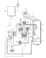
図1は、この発明に係る蒸発燃料処理装置の一実施例を示す構成説明図である。図示せぬ車両に、内燃機関1が搭載されているとともに、密閉型の燃料タンク2が設けられており、給油時に燃料タンク2内で発生した蒸発燃料を処理するために、キャニスタ3を用いた蒸発燃料処理装置が設けられている。上記燃料タンク2は、先端の給油口5aにフィラーキャップ4が着脱可能に装着された給油管部5を備えており、また、内燃機関1の燃料噴射装置6へ燃料を供給する燃料ポンプユニット7が燃料タンク2内部に収容されている。上記給油口5aは、燃料タンク2内の圧力が高い状態でのフィラーキャップ4の開放を制限するために、電気的にロックされるフューエルリッド8で覆われている。このフューエルリッド8は、運転席等に設けられたリッドオープンスイッチ9の信号に基づき、燃料タンク2内の圧力が低下した状態でロック解除される。なお、フューエルリッド8のロックに代えて、フィラーキャップ4自体をロックするようにしてもよい。
FIG. 1 is an explanatory diagram showing a configuration of an embodiment of an evaporative fuel processing apparatus according to the present invention. A vehicle (not shown) is equipped with an
上記キャニスタ3は、合成樹脂製のケースによってUターン形状に流路が形成され、その内部に活性炭等からなる吸着材が充填されたものであって、Uターン形状をなす流路の流れ方向の一端部に、蒸発燃料の流入部となるチャージポート13と、燃料成分を含むパージガスの流出部となるパージポート14と、が設けられており、流れ方向の他端部に、パージの際に外気を取り込むためのドレンポート15が設けられている。
The
上記チャージポート13は、蒸発燃料通路16を介して燃料タンク2の上部空間に接続されている。なお、この蒸発燃料通路16の燃料タンク2側の先端部は、燃料液面が高い位置にあるときに液体燃料が蒸発燃料通路16内に溢れ出ることを防止するFLVバルブ20を介して燃料タンク2の上部空間に連通している。そして、上記蒸発燃料通路16の通路途中には、該蒸発燃料通路16を開閉する封鎖弁21が設けられている。この封鎖弁21は、原則として給油時以外はキャニスタ3と燃料タンク2との間を遮断して燃料タンク2を密閉状態とするためのものであって、非通電時に閉となる常閉型電磁弁から構成されている。
The
上記パージポート14は、内燃機関1の吸気系、例えば吸気通路17のスロットル弁18下流側に、パージ通路19を介して接続されている。上記パージ通路19には、内燃機関1へのパージガスの導入を制御するために該パージ通路19を開閉する第1パージ制御弁23が設けられている。内燃機関1の停止時のほか、未暖機時やフューエルカット時など所定の条件のときには、パージガスの導入を禁止するために、第1パージ制御弁23が閉となる。上記第1パージ制御弁23は、やはり常閉型電磁弁から構成されている。
The
上記ドレンポート15には、フィルタ24を介して先端が大気開放されたドレン通路25が接続されており、かつこのドレン通路25に、該ドレン通路25を開閉するドレンカットバルブ26が設けられている。このドレンカットバルブ26は、非通電時に開となる常開型電磁弁から構成されている。このドレンカットバルブ26は、リーク診断の際に系を閉じるほか、例えば、キャニスタ3の破過を何らかの手段で検知した場合などに閉じられ得るが、基本的には開状態となってドレン通路25を開放している。また、上記ドレン通路25には、上記ドレンカットバルブ26と並列に、キャニスタ3へ向けて大気を圧送する加圧用ポンプ27が設けられている。この加圧用ポンプ27と上記ドレンカットバルブ26は、リーク診断モジュール28として一体に構成されている。
The
上記蒸発燃料通路16と上記パージ通路19との間、詳しくは、蒸発燃料通路16の封鎖弁21よりも燃料タンク2側の位置とパージ通路19の第1パージ制御弁23よりも上流側(つまりキャニスタ3側)の位置との間に、両者を連通するタンク開放通路31が設けられている。そして、このタンク開放通路31の通路途中には、該タンク開放通路31を開閉する「第2の制御弁」に相当する第2パージ制御弁32が設けられている。なお、タンク開放通路31は、機能的には燃料タンク2とキャニスタ3とを連通させるためのものであり、従って、蒸発燃料通路16の燃料タンク2寄りの部分ならびにパージ通路19のキャニスタ3寄りの部分は、機能的に、タンク開放通路31を兼ねたものと言える。
More specifically, between the
上記第2パージ制御弁32は、非通電時に閉となる常閉型電磁弁から構成されている。ここで、第2パージ制御弁32としては、その通路面積が封鎖弁21の通路面積よりも小さなものが用いられる。具体的には、プランジャでもって開閉されるポートの口径が、封鎖弁21に比較して第2パージ制御弁32の方が小径となっている。なお、封鎖弁21は、円滑な給油を損なわないように、十分に大きな通路面積を有している。
The second
上記の封鎖弁21、第1パージ制御弁23、第2パージ制御弁32、ドレンカットバルブ26、および加圧用ポンプ27は、内燃機関1の種々の制御(例えば、燃料噴射量制御、噴射時期制御、点火時期制御、スロットル弁18の開度制御など)を行うエンジンコントロールユニット35によって適宜に制御され、後述するように、給油に際してのフィラーキャップ4開放前のタンク内圧力の低減、給油時の吸着処理、機関運転中のパージ処理、系の各部のリーク診断、第2パージ制御弁32の固着診断、などが実行される。また、系内の圧力を検出する圧力センサとして、燃料タンク2にタンク圧センサ36が取り付けられているとともに、キャニスタ3のパージポート14近傍にエバポレーションライン圧(以下、エバポライン圧と略記する)センサ37が取り付けられている。前者のタンク圧センサ36は、封鎖弁21および第2パージ制御弁32により画成される系内の燃料タンク2側の領域の圧力(具体的には燃料タンク2の上部空間の圧力)を検出し、後者のエバポライン圧センサ37は、封鎖弁21と第2パージ制御弁32とドレンカットバルブ26と第1パージ制御弁23とによって囲まれた系内のキャニスタ3を含む領域の圧力を検出する。
The blocking
なお、燃料タンク2内の圧力が異常に高圧になったときに機械的に開く正圧側リリーフ弁および燃料タンク2内の圧力が異常に低圧になったときに機械的に開く負圧側リリーフ弁を必要に応じて設けることができるが、図1には、これらのリリーフ弁は図示していない。
A positive pressure relief valve that opens mechanically when the pressure in the
上記のように構成された蒸発燃料処理装置は、基本的に、給油時に発生する蒸発燃料のみがキャニスタ3に吸着され、給油時以外は、キャニスタ3による蒸発燃料の吸着は行われない。すなわち、この実施例の蒸発燃料処理装置は、内燃機関1を停止させた状態でのいわゆるEV走行が可能なハイブリッド車両に好適なものであり、この種の車両では、キャニスタ3のパージの機会が少なくなることから、キャニスタ3による蒸発燃料の吸着を給油時に限定しているのである。
In the evaporative fuel processing apparatus configured as described above, basically only the evaporative fuel generated during refueling is adsorbed to the
給油中は、ドレンカットバルブ26が開いている状態において、第1パージ制御弁23および第2パージ制御弁32が閉、封鎖弁21が開、となり、燃料タンク2内とキャニスタ3のチャージポート13とが連通状態となる。従って、給油に伴って燃料タンク2内で発生した蒸発燃料は、キャニスタ3に導入され、内部の吸着材に吸着される。
During refueling, in a state where the drain cut
そして、給油が終わると、封鎖弁21が閉となる。従って、燃料タンク2内がキャニスタ3から分離した密閉状態に保たれ、内燃機関1の停止中は、キャニスタ3の吸着量は基本的に増減しない。
And when refueling is completed, the blocking
その後、車両の運転が開始され、内燃機関1が所定の運転状態となると、封鎖弁21を閉とした状態のまま、第1パージ制御弁23が適宜に開かれ、キャニスタ3からの燃料成分のパージが行われる。つまり、内燃機関1の吸気系との圧力差によってドレンポート15から大気が導入され、この大気により吸着材からパージされた燃料成分が、第1パージ制御弁23を通して内燃機関1の吸気通路17へと導入される。従って、内燃機関1の運転中に、キャニスタ3の吸着量は徐々に減少する。ここで、上記実施例では、第1パージ制御弁23を介したキャニスタ3のパージ中に、第2パージ制御弁32が開となり、キャニスタ3のパージと並行して、燃料タンク2内の圧力の開放ならびに燃料タンク2内の蒸発燃料の処理(キャニスタ3を使用しない直接的な処理)が行われる。
Thereafter, when the operation of the vehicle is started and the
このように上記の蒸発燃料処理装置では、内燃機関1の運転中は、燃料タンク2内の蒸発燃料が内燃機関1でもって積極的に処理されるため、給油時に燃料タンク2内に残存している蒸発燃料が比較的少なくなる。そして、この内燃機関1による燃料タンク2内の蒸発燃料の直接的な処理の際には、蒸発燃料がキャニスタ3を経由することがないので、キャニスタ3の吸着量の増加は生じない。また、内燃機関1の運転中に燃料タンク2内の圧力が頻繁に開放されることとなり、その高圧化が抑制される。
As described above, in the above-described evaporated fuel processing apparatus, during the operation of the
上記第2パージ制御弁32は、さらに、給油開始時の燃料タンク2内の圧力の開放に利用される。すなわち、給油中は上述のように封鎖弁21が開となるが、燃料タンク2内の圧力が高圧となっている状態で通路面積の大きな封鎖弁21が開くと、キャニスタ3を通してドレンポート15から外部へ蒸発燃料が吹き抜ける懸念がある。そのため、上記実施例では、リッドオープンスイッチ9の操作を検出したときに、ドレンカットバルブ26が開いている状態で、まず第2パージ制御弁32が開弁する。これにより燃料タンク2内の圧力がキャニスタ3を通して開放される。そして、燃料タンク2内の圧力が大気圧に近付いた状態において、封鎖弁21が開となり、燃料タンク2内が大気圧下に開放される。第2パージ制御弁32の通路面積ないし口径は封鎖弁21よりも小さいので、キャニスタ3を通した初期の圧力の開放がある程度緩慢に行われ、蒸発燃料の吹き抜けが抑制される。つまり、第2パージ制御弁32と封鎖弁21とによって圧力の開放が2段階に行われることになり、蒸発燃料の吹き抜けを抑制しつつ速やかな圧力開放を実現できる。そして、封鎖弁21として、十分に大きな通路面積のものを用いることができるため、給油時に通路抵抗とならず、給油が円滑となる。なお、単一の封鎖弁でもって2段階の開度制御を行う場合に比較して、上記実施例では、個々の封鎖弁21および第2パージ制御弁32の構成ならびに制御が単純となる。しかも、燃料タンク2内の圧力が高圧である状態で開弁する第2パージ制御弁32は、封鎖弁21に比較して口径が小さいので、高圧下での開弁に必要なソレノイドの推力が少なくて済む利点がある。
The second
また上記実施例では、第2パージ制御弁32と第1パージ制御弁23とが燃料タンク2と吸気通路17との間に直列に配置された構成であるので、実際の車両内でのレイアウトとして、内燃機関1(吸気通路17)とキャニスタ3との間の配管が1本で済み、特にキャニスタ3を燃料タンク2の近傍に配置する場合に有利となる。また、上述した給油開始時の燃料タンク2内の圧力の開放の際に、第2パージ制御弁32の下流に第1パージ制御弁23が存在するので、吸気通路17側へ蒸発燃料が流れ込むことがない。
In the above embodiment, since the second
次に、図2は、種々のモードにおける各弁の開閉状態やガスの流れを示した動作説明図であって、以下、これに基づいて、上記の蒸発燃料処理装置の動作をさらに具体的に説明する。 Next, FIG. 2 is an operation explanatory view showing the open / closed state of each valve and the flow of gas in various modes, and based on this, the operation of the above-mentioned evaporated fuel processing device will be more specifically described below. explain.
図2の(a)は、給油中の状態を示しており、上述したように、ドレンカットバルブ26が開、第1パージ制御弁23および第2パージ制御弁32が閉、封鎖弁21が開、となる。給油に伴って燃料タンク2から押し出された蒸発燃料を含むガスは、キャニスタ3を経て外部へ流れる。蒸発燃料は、キャニスタ3に吸着される。上述したように、封鎖弁21として十分な口径のものを用いることで、円滑な給油を損なうことがない。
FIG. 2 (a) shows a state during refueling. As described above, the drain cut
図2の(b)は、内燃機関1の運転中に、燃料タンク2内の圧力の開放ならびに燃料タンク2内の蒸発燃料の直接的な処理を行っている状態を示している。上述したように、この燃料タンク2内の蒸発燃料の処理は、キャニスタ3のパージに並行して行うものであり、ドレンカットバルブ26が開、第1パージ制御弁23および第2パージ制御弁32が開、封鎖弁21が閉、となる。従って、大気がドレンカットバルブ26を介してキャニスタ3を通過し、パージガスとなって内燃機関の吸気通路17へ導入される。同時に、燃料タンク2内の蒸発燃料が第2パージ制御弁32および第1パージ制御弁23を通して吸気通路17へ導入される。封鎖弁21は閉じているので、蒸発燃料がキャニスタ3へ迂回することはない。
FIG. 2B shows a state in which the pressure in the
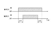
ここで、第2パージ制御弁32は、第1パージ制御弁23の開弁期間に対し、図3に示すような期間で開弁するように制御される。すなわち、内燃機関1の運転中に所定のパージ条件が成立して第1パージ制御弁23が開弁した後、適宜な遅れ期間Δt1の後、第2パージ制御弁32が開弁する。これは、第1パージ制御弁23を開いてから第2パージ制御弁32付近の圧力が確実に負圧となっている状態で第2パージ制御弁32を開くことで、蒸発燃料の逆流を確実に防止するようにしたものであって、遅れ期間Δt1は、第1パージ制御弁23からキャニスタ3を経由して大気開口部に至るまでの通路面積および通路長に応じて決定され、例えばソフトウェア上のタイマによって制御される。
Here, the second
また、キャニスタ3のパージ完了あるいはパージ条件からの逸脱によりパージを終了する際には、逆に第2パージ制御弁32が先行して閉じ、適宜な遅れ期間Δt2の後、第1パージ制御弁23が閉弁する。これは、やはり、燃料タンク2からの蒸発燃料がキャニスタ3側へ向かわないないようにすることを確実にするためのものであり、遅れ期間Δt2は、第2パージ制御弁32から第1パージ制御弁23に至るまでの通路面積および通路長に応じて決定され、例えばソフトウェア上のタイマによって制御される。なお、通路長の差異により、閉じ側の遅れ期間Δt2は、一般に開き側の遅れ期間Δt1よりも短いものとなる。
On the other hand, when the purging of the
図2の(c)は、給油開始直前に実行される燃料タンク2内の圧力開放のための動作を示しており、ドレンカットバルブ26が開、第1パージ制御弁23が閉、第2パージ制御弁32が開、封鎖弁21が閉、となる。燃料タンク2内の高い圧力は、通路面積が小さい第2パージ制御弁32を介してキャニスタ3から外部へと開放される。上述したように、燃料タンク2内の圧力が大気圧に近付いた段階で第2パージ制御弁32が閉じるとともに封鎖弁21(c)が開き、図2(a)に示す状態に移行する。
FIG. 2C shows an operation for releasing the pressure in the
図2の(d),(e)は、蒸発燃料処理装置のリーク診断を説明するための動作説明図であって、例えば車両の停車後に、加圧用ポンプ27を用いて系内を加圧し、その後の圧力低下の有無からリークの有無を判定する。ここで、封鎖弁21の開放に伴う蒸発燃料の流出を回避するために、最初に、図2(d)に示すように、封鎖弁21および第2パージ制御弁32を、第1パージ制御弁23およびドレンカットバルブ26とともに閉弁した状態において、加圧用ポンプ27を作動させ、キャニスタ3側の加圧を行う。そして、エバポライン圧センサ37によって検出されるキャニスタ3側の圧力がタンク圧センサ36によって検出される燃料タンク2側の圧力以上となった段階で、図2(e)に示すように封鎖弁21を開放し、加圧用ポンプ27によって系内全体を加圧状態とする。系内が所定の加圧状態となったら加圧用ポンプ27を停止し、エバポライン圧センサ33およびタンク圧センサ36によって、その後の圧力変化を監視する。所定時間内に所定レベルの圧力低下が検出されなければ、リークがないものと診断する。
FIGS. 2D and 2E are operation explanatory views for explaining a leakage diagnosis of the evaporated fuel processing apparatus. For example, after the vehicle is stopped, the inside of the system is pressurized using the pressurizing
なお、系をキャニスタ3側と燃料タンク2側との2つの領域に分けて、各々のリーク診断を順次行うことも可能である。この場合、封鎖弁21を閉じた状態でキャニスタ3側の加圧を行った後、エバポライン圧センサ37を用いた圧力変化の監視によりキャニスタ3側の領域のリーク診断を行う。次いで、封鎖弁21を一旦開いて系内全体を加圧状態とした後、封鎖弁21を再び閉じ、タンク圧センサ36を用いた圧力変化の監視により燃料タンク2側のリーク診断を行う。
It is also possible to divide the system into two regions, the
次に、図4のフローチャートに基づいて、上記第2パージ制御弁32の固着診断について説明する。本実施例では、図2の(c)に基づいて説明した上述の給油開始直前に実行される燃料タンク2内の圧力開放の際に、同時に、第2パージ制御弁32の固着診断が実行される。
Next, the sticking diagnosis of the second
ステップ1では、リッドオープンスイッチ9がON操作されたか否かを繰り返し判定する。リッドオープンスイッチ9がONとなったら、ステップ2へ進み、第2パージ制御弁32を開く。なお、第1パージ制御弁23および封鎖弁21が開状態にあった場合には、ステップ2で同時にこれらを閉とする。ステップ3では、第2パージ制御弁32を開く前の燃料タンク2内の初期の圧力P0が、診断に必要な所定の圧力P1(但しP1は正圧)以上であるか判定する。圧力P1未満であった場合には、診断精度が低くなることから診断は行わない。圧力P1以上であれば、ステップ4へ進み、第2パージ制御弁32の診断を開始する。具体的には、上述の初期の圧力P0の値を記憶するとともに、その後の燃料タンク2内の圧力を監視する。
In
ステップ5では、リッドオープンスイッチ9のON操作から所定時間T1が経過したか否かを判定する。この所定時間T1は、後述する所定時間T2よりも短いものとして設定される。所定時間T1が経過した時点でステップ6へ進み、第2パージ制御弁32の開弁に伴う燃料タンク2内の圧力低下量ΔPが絶対値として所定の閾値ΔP1よりも大きいか否かを判定する。ここで閾値ΔP1よりも圧力低下量ΔPが大きければ、第2パージ制御弁32を通したガスの通流が正常になされているものとして、第2パージ制御弁32が正常に動作しているものと判定する(ステップ7)。他方、圧力低下量ΔPが閾値ΔP1以下である場合には、第2パージ制御弁32の固着や目詰まり等の異常であると判定し、図示せぬ警告灯の点灯等により運転者への報知を行う(ステップ8)。
In
次のステップ9では、リッドオープンスイッチ9のON操作から所定時間T2が経過したか否かを判定する。所定時間T2は、燃料タンク2内の圧力が想定される高圧状態にあったときに、封鎖弁21開弁時に吹き抜けが生じない程度にまで大気圧に近付けるのに必要な時間に相当する。この所定時間T2が経過したときに、ステップ10へ進み、封鎖弁21を開とするとともに第2パージ制御弁32を閉とする。この封鎖弁21の開弁により燃料タンク2内の圧力は速やかに大気圧下に開放される。そして、ステップ11において、フューエルリッド8のロックが解除され、フィラーキャップ4の取り外しが許可される。なお、ステップ10で第2パージ制御弁32を閉弁せずに、給油終了まで封鎖弁21とともに開弁状態に保持するようにしてもよい。
In the
図5は、上記のフローチャートに基づく給油開始直前の動作を示したタイムチャートであり、図示するように、リッドオープンスイッチ9がON操作される前は、封鎖弁21および第2パージ制御弁32がいずれも閉じており、燃料タンク2が密閉されている。そのため、燃料タンク2内で発生する蒸発燃料によって、燃料タンク2内の圧力は、多くの場合、大気圧よりも高圧となっている。リッドオープンスイッチ9がON操作されると、第2パージ制御弁32が開弁し、これに伴って、燃料タンク2内の圧力は、実線aで示すように比較的緩やかに低下する。そして、所定時間T2経過後に封鎖弁21が開弁し、燃料タンク2内の圧力が速やかに大気圧となる。ここで、仮に第2パージ制御弁32が閉状態のまま固着していると、燃料タンク2内の圧力は、仮想線bで示すように高い値を維持する。従って、所定時間T1経過時点の圧力低下量から第2パージ制御弁32の異常を検出することができる。なお、実施例では所定時間T1経過時点の圧力低下量から異常の診断を行うが、初期段階の圧力から所定量低下するまでの経過時間から診断を行うことも可能である。
FIG. 5 is a time chart showing the operation immediately before the start of refueling based on the above flow chart. As shown in the figure, before the lid
このように、上記実施例では、給油のたびに第2パージ制御弁32の診断が実行され、正常に開動作していることが保証される。この診断は、給油のための燃料タンク2内の圧力開放の制御を利用して並行して実行されるので、不必要なガスの移動やポンプの駆動等を伴わずに行うことができる。なお、第2パージ制御弁32の開弁したままの固着(いわゆる開固着)は、前述した燃料タンク2側の領域のリーク診断を利用して診断することが可能である。
Thus, in the above-described embodiment, the diagnosis of the second
以上、この発明の一実施例を詳細に説明したが、本発明は上記実施例に限定されるものではなく、種々の変更が可能である。例えば、給油のための圧力開放動作とは別のタイミングで第2パージ制御弁32の診断を行うようにしてもよい。また、本発明は、ハイブリッド車両に限らず、内燃機関と燃料タンクとを備えた車両に広く適用することができる。
As mentioned above, although one Example of this invention was described in detail, this invention is not limited to the said Example, A various change is possible. For example, the diagnosis of the second
1…内燃機関
2…燃料タンク
3…キャニスタ
9…リッドオープンスイッチ
16…蒸発燃料通路
19…パージ通路
21…封鎖弁
23…第1パージ制御弁
26…ドレンカットバルブ
27…加圧用ポンプ
31…タンク開放通路
32…第2パージ制御弁
36…タンク圧センサ
37…エバポライン圧センサ
DESCRIPTION OF
Claims (8)
この蒸発燃料通路を開閉するように該蒸発燃料通路に介装され、給油時に開となる電磁弁からなる封鎖弁と、
上記燃料タンクと上記キャニスタとを連通するタンク開放通路と、
このタンク開放通路に介装され、給油のための圧力開放時に上記封鎖弁の開弁に先行して開弁する第2の制御弁と、
上記燃料タンク内の圧力を検出するタンク圧センサと、
上記封鎖弁および上記第2の制御弁が閉でかつ上記燃料タンク内の圧力が正圧である状態から上記第2の制御弁を開弁し、その後の上記燃料タンク内の圧力変化から当該第2の制御弁の診断を行う診断手段と、
を備えてなる蒸発燃料処理装置。 An evaporative fuel passage communicating the fuel tank and the charge port of the canister;
The interposed evaporated fuel passage to the fuel vapor passage so as to open and close, the closing valve comprising a solenoid valve which is opened during fueling,
A tank opening passage communicating the fuel tank and the canister;
A second control valve interposed in the tank opening passage and opened prior to the opening of the blocking valve when the pressure for refueling is released;
A tank pressure sensor for detecting the pressure in the fuel tank;
The second control valve is opened from a state in which the closing valve and the second control valve are closed and the pressure in the fuel tank is positive, and the pressure change in the fuel tank thereafter is changed to the first. Diagnostic means for diagnosing the two control valves;
An evaporative fuel processing apparatus comprising:
上記診断手段は、上記所定時間が経過する前に、上記燃料タンク内の圧力変化から上記診断を行う、請求項3に記載の蒸発燃料処理装置。 During pressure release for refueling, blocking valve from opening of the second control valve after a predetermined time has elapsed is opened,
It said diagnosis means, before the predetermined time elapses, performs the diagnosis from the pressure change in the fuel tank, fuel vapor processing apparatus according to claim 3.
このパージ通路に介装され、該パージ通路を開閉するパージ制御弁と、 A purge control valve interposed in the purge passage and opening and closing the purge passage;
をさらに備え、 Further comprising
上記タンク開放通路は、上記パージ通路の上記パージ制御弁よりもキャニスタ側の位置に接続されて、上記キャニスタに連通している、請求項1〜5のいずれかに記載の蒸発燃料処理装置。 The evaporated fuel processing apparatus according to claim 1, wherein the tank opening passage is connected to a position closer to the canister than the purge control valve of the purge passage and communicates with the canister.
Priority Applications (4)
| Application Number | Priority Date | Filing Date | Title |
|---|---|---|---|
| JP2014108637A JP6287581B2 (en) | 2014-05-27 | 2014-05-27 | Evaporative fuel processing equipment |
| US15/303,559 US9797346B2 (en) | 2014-05-27 | 2015-04-06 | Fuel evaporative emission processing system |
| CN201580027486.0A CN106574575B (en) | 2014-05-27 | 2015-04-06 | Evaporated fuel treating apparatus |
| PCT/JP2015/060699 WO2015182249A1 (en) | 2014-05-27 | 2015-04-06 | Fuel vapor treatment device |
Applications Claiming Priority (1)
| Application Number | Priority Date | Filing Date | Title |
|---|---|---|---|
| JP2014108637A JP6287581B2 (en) | 2014-05-27 | 2014-05-27 | Evaporative fuel processing equipment |
Publications (2)
| Publication Number | Publication Date |
|---|---|
| JP2015224565A JP2015224565A (en) | 2015-12-14 |
| JP6287581B2 true JP6287581B2 (en) | 2018-03-07 |
Family
ID=54698590
Family Applications (1)
| Application Number | Title | Priority Date | Filing Date |
|---|---|---|---|
| JP2014108637A Expired - Fee Related JP6287581B2 (en) | 2014-05-27 | 2014-05-27 | Evaporative fuel processing equipment |
Country Status (4)
| Country | Link |
|---|---|
| US (1) | US9797346B2 (en) |
| JP (1) | JP6287581B2 (en) |
| CN (1) | CN106574575B (en) |
| WO (1) | WO2015182249A1 (en) |
Families Citing this family (12)
| Publication number | Priority date | Publication date | Assignee | Title |
|---|---|---|---|---|
| WO2015182174A1 (en) * | 2014-05-27 | 2015-12-03 | 日産自動車株式会社 | Vaporized fuel processing device |
| JP6421927B2 (en) * | 2014-12-22 | 2018-11-14 | 三菱自動車工業株式会社 | Fuel evaporative emission control device |
| JP6634810B2 (en) * | 2015-12-16 | 2020-01-22 | 三菱自動車工業株式会社 | Evaporative fuel processing equipment |
| JP6634997B2 (en) * | 2016-10-07 | 2020-01-22 | 株式会社デンソー | Evaporative fuel processing system |
| FR3074232B1 (en) | 2017-11-27 | 2019-10-18 | Continental Automotive France | METHOD FOR DETECTING A GAS FLOW FAULT IN A VENTILATION LINE OF A PURGE DEVICE |
| FR3078747B1 (en) * | 2018-03-08 | 2020-02-14 | Continental Automotive France | LEAK DETECTION IN A DEVICE FOR EVAPORATING VAPORS OF A FUEL STORED IN A TANK OF A VEHICLE ENGINE |
| EP3575587A1 (en) | 2018-05-31 | 2019-12-04 | Stoneridge, Inc. | Evaporative emissions control system leak check module including first and second solenoid valves |
| JP7195886B2 (en) * | 2018-11-16 | 2022-12-26 | 株式会社Subaru | Fuel tank pressure sensor failure determination device |
| US11078844B2 (en) * | 2018-11-21 | 2021-08-03 | Raytheon Technologies Corporation | Thermal gradient reducing device for gas turbine engine component |
| US11168648B2 (en) * | 2019-06-03 | 2021-11-09 | Ford Global Technologies, Llc | Systems and methods for vehicle fuel system and evaporative emissions system diagnostics |
| JP7123013B2 (en) * | 2019-07-01 | 2022-08-22 | 愛三工業株式会社 | Evaporative fuel processing device |
| JP7124811B2 (en) * | 2019-09-04 | 2022-08-24 | トヨタ自動車株式会社 | engine device |
Family Cites Families (15)
| Publication number | Priority date | Publication date | Assignee | Title |
|---|---|---|---|---|
| DE4132055A1 (en) * | 1991-09-26 | 1993-04-01 | Bosch Gmbh Robert | METHOD AND DEVICE FOR TESTING THE FUNCTIONALITY OF A TANK BLEEDING SYSTEM |
| JP3183431B2 (en) * | 1993-06-07 | 2001-07-09 | 本田技研工業株式会社 | Evaporative fuel processor for internal combustion engines |
| JPH07217505A (en) * | 1994-02-02 | 1995-08-15 | Toyota Motor Corp | Evaporated fuel treatment device for internal combustion engine |
| JPH08232777A (en) * | 1995-02-22 | 1996-09-10 | Suzuki Motor Corp | Vaporizing fuel control device for internal combustion engine |
| JP3134704B2 (en) * | 1995-02-22 | 2001-02-13 | スズキ株式会社 | Evaporative fuel control system for internal combustion engine |
| JP3284881B2 (en) * | 1996-05-16 | 2002-05-20 | トヨタ自動車株式会社 | Failure diagnosis device for fuel vapor processing unit |
| US6658923B2 (en) * | 2000-02-22 | 2003-12-09 | Siemens Automotive S.A. | Leak detection a vapor handling system |
| JP3776344B2 (en) * | 2001-10-03 | 2006-05-17 | 本田技研工業株式会社 | Failure diagnosis device for evaporative fuel treatment equipment |
| JP4110932B2 (en) | 2002-11-05 | 2008-07-02 | トヨタ自動車株式会社 | Evaporative fuel processing device for internal combustion engine |
| JP4370825B2 (en) * | 2003-06-25 | 2009-11-25 | トヨタ自動車株式会社 | Control device for sealed fuel tank system |
| DE102010031216B4 (en) * | 2009-09-18 | 2024-03-14 | Robert Bosch Gmbh | Method for testing the functionality of a tank shut-off valve in a fuel tank system |
| US8813726B2 (en) * | 2011-03-28 | 2014-08-26 | Toyota Jidosha Kabushiki Kaisha | Fuel tank system |
| JP5704338B2 (en) * | 2011-07-07 | 2015-04-22 | 三菱自動車工業株式会社 | Fuel evaporative emission control device for internal combustion engine |
| JP5500182B2 (en) * | 2012-01-05 | 2014-05-21 | 三菱自動車工業株式会社 | Fuel evaporative emission control device |
| JP5880159B2 (en) * | 2012-03-09 | 2016-03-08 | 日産自動車株式会社 | Evaporative fuel processor diagnostic device |
-
2014
- 2014-05-27 JP JP2014108637A patent/JP6287581B2/en not_active Expired - Fee Related
-
2015
- 2015-04-06 US US15/303,559 patent/US9797346B2/en not_active Expired - Fee Related
- 2015-04-06 WO PCT/JP2015/060699 patent/WO2015182249A1/en active Application Filing
- 2015-04-06 CN CN201580027486.0A patent/CN106574575B/en not_active Expired - Fee Related
Also Published As
| Publication number | Publication date |
|---|---|
| US9797346B2 (en) | 2017-10-24 |
| CN106574575B (en) | 2019-03-15 |
| WO2015182249A1 (en) | 2015-12-03 |
| CN106574575A (en) | 2017-04-19 |
| US20170030303A1 (en) | 2017-02-02 |
| JP2015224565A (en) | 2015-12-14 |
Similar Documents
| Publication | Publication Date | Title |
|---|---|---|
| JP6287581B2 (en) | Evaporative fuel processing equipment | |
| JP6299867B2 (en) | Evaporative fuel processing equipment | |
| JP6443548B2 (en) | Evaporative fuel processor diagnostic device | |
| JP5998529B2 (en) | Evaporative fuel processor diagnostic device | |
| JP5880159B2 (en) | Evaporative fuel processor diagnostic device | |
| JP5582367B2 (en) | Evaporative fuel processing equipment | |
| JP2006118473A (en) | Evaporated fuel treatment device of internal combustion engine | |
| CN108301942B (en) | Fuel tank system and control method of fuel tank system | |
| JP6380676B2 (en) | Evaporative fuel processing equipment | |
| JP6251469B2 (en) | Evaporative fuel processor diagnostic device | |
| JP2015121113A (en) | Fuel evaporative emission control system | |
| EP3135893B1 (en) | Evaporated fuel treatment device | |
| JP2006138247A (en) | Fuel vapor discharge-preventing system | |
| US9617932B2 (en) | Transpiration fuel treatment apparatus | |
| JP5891973B2 (en) | Fuel vapor treatment equipment |
Legal Events
| Date | Code | Title | Description |
|---|---|---|---|
| A621 | Written request for application examination |
Free format text: JAPANESE INTERMEDIATE CODE: A621 Effective date: 20170127 |
|
| A131 | Notification of reasons for refusal |
Free format text: JAPANESE INTERMEDIATE CODE: A131 Effective date: 20171114 |
|
| A521 | Written amendment |
Free format text: JAPANESE INTERMEDIATE CODE: A523 Effective date: 20171212 |
|
| TRDD | Decision of grant or rejection written | ||
| A01 | Written decision to grant a patent or to grant a registration (utility model) |
Free format text: JAPANESE INTERMEDIATE CODE: A01 Effective date: 20180109 |
|
| A61 | First payment of annual fees (during grant procedure) |
Free format text: JAPANESE INTERMEDIATE CODE: A61 Effective date: 20180122 |
|
| R151 | Written notification of patent or utility model registration |
Ref document number: 6287581 Country of ref document: JP Free format text: JAPANESE INTERMEDIATE CODE: R151 |
|
| LAPS | Cancellation because of no payment of annual fees |