JP6285966B2 - Method of operating an interface connecting a cable and a receiver to a physiological monitor - Google Patents
Method of operating an interface connecting a cable and a receiver to a physiological monitor Download PDFInfo
- Publication number
- JP6285966B2 JP6285966B2 JP2015559574A JP2015559574A JP6285966B2 JP 6285966 B2 JP6285966 B2 JP 6285966B2 JP 2015559574 A JP2015559574 A JP 2015559574A JP 2015559574 A JP2015559574 A JP 2015559574A JP 6285966 B2 JP6285966 B2 JP 6285966B2
- Authority
- JP
- Japan
- Prior art keywords
- cable
- monitor
- voltage
- signal
- physiological parameter
- Prior art date
- Legal status (The legal status is an assumption and is not a legal conclusion. Google has not performed a legal analysis and makes no representation as to the accuracy of the status listed.)
- Active
Links
- 238000000034 method Methods 0.000 title claims description 22
- 230000005284 excitation Effects 0.000 claims description 31
- 230000036772 blood pressure Effects 0.000 claims description 30
- 230000035945 sensitivity Effects 0.000 claims description 4
- 239000002131 composite material Substances 0.000 claims 1
- 238000001914 filtration Methods 0.000 claims 1
- 238000010586 diagram Methods 0.000 description 8
- 238000005259 measurement Methods 0.000 description 6
- 238000012544 monitoring process Methods 0.000 description 6
- 238000009530 blood pressure measurement Methods 0.000 description 3
- 208000031481 Pathologic Constriction Diseases 0.000 description 2
- 230000003321 amplification Effects 0.000 description 2
- 230000005540 biological transmission Effects 0.000 description 2
- 230000017531 blood circulation Effects 0.000 description 2
- 230000036760 body temperature Effects 0.000 description 2
- 238000013461 design Methods 0.000 description 2
- 238000012986 modification Methods 0.000 description 2
- 230000004048 modification Effects 0.000 description 2
- 238000003199 nucleic acid amplification method Methods 0.000 description 2
- 230000008569 process Effects 0.000 description 2
- 238000012545 processing Methods 0.000 description 2
- 208000037804 stenosis Diseases 0.000 description 2
- 230000036262 stenosis Effects 0.000 description 2
- 210000000709 aorta Anatomy 0.000 description 1
- 210000001367 artery Anatomy 0.000 description 1
- 239000003990 capacitor Substances 0.000 description 1
- 230000000747 cardiac effect Effects 0.000 description 1
- 230000008859 change Effects 0.000 description 1
- 238000004891 communication Methods 0.000 description 1
- 210000004351 coronary vessel Anatomy 0.000 description 1
- 210000001105 femoral artery Anatomy 0.000 description 1
- 239000012530 fluid Substances 0.000 description 1
- 230000006698 induction Effects 0.000 description 1
- 239000000463 material Substances 0.000 description 1
- QSHDDOUJBYECFT-UHFFFAOYSA-N mercury Chemical compound [Hg] QSHDDOUJBYECFT-UHFFFAOYSA-N 0.000 description 1
- 229910052753 mercury Inorganic materials 0.000 description 1
- 238000012806 monitoring device Methods 0.000 description 1
- 230000008054 signal transmission Effects 0.000 description 1
- 230000000087 stabilizing effect Effects 0.000 description 1
- 229910001220 stainless steel Inorganic materials 0.000 description 1
- 239000010935 stainless steel Substances 0.000 description 1
- 238000006467 substitution reaction Methods 0.000 description 1
Images


Classifications
-
- A—HUMAN NECESSITIES
- A61—MEDICAL OR VETERINARY SCIENCE; HYGIENE
- A61B—DIAGNOSIS; SURGERY; IDENTIFICATION
- A61B5/00—Measuring for diagnostic purposes; Identification of persons
- A61B5/72—Signal processing specially adapted for physiological signals or for diagnostic purposes
- A61B5/7225—Details of analog processing, e.g. isolation amplifier, gain or sensitivity adjustment, filtering, baseline or drift compensation
-
- H—ELECTRICITY
- H03—ELECTRONIC CIRCUITRY
- H03L—AUTOMATIC CONTROL, STARTING, SYNCHRONISATION, OR STABILISATION OF GENERATORS OF ELECTRONIC OSCILLATIONS OR PULSES
- H03L5/00—Automatic control of voltage, current, or power
-
- A—HUMAN NECESSITIES
- A61—MEDICAL OR VETERINARY SCIENCE; HYGIENE
- A61B—DIAGNOSIS; SURGERY; IDENTIFICATION
- A61B5/00—Measuring for diagnostic purposes; Identification of persons
- A61B5/02—Detecting, measuring or recording pulse, heart rate, blood pressure or blood flow; Combined pulse/heart-rate/blood pressure determination; Evaluating a cardiovascular condition not otherwise provided for, e.g. using combinations of techniques provided for in this group with electrocardiography or electroauscultation; Heart catheters for measuring blood pressure
- A61B5/021—Measuring pressure in heart or blood vessels
-
- A—HUMAN NECESSITIES
- A61—MEDICAL OR VETERINARY SCIENCE; HYGIENE
- A61B—DIAGNOSIS; SURGERY; IDENTIFICATION
- A61B5/00—Measuring for diagnostic purposes; Identification of persons
- A61B5/72—Signal processing specially adapted for physiological signals or for diagnostic purposes
- A61B5/7203—Signal processing specially adapted for physiological signals or for diagnostic purposes for noise prevention, reduction or removal
-
- A—HUMAN NECESSITIES
- A61—MEDICAL OR VETERINARY SCIENCE; HYGIENE
- A61B—DIAGNOSIS; SURGERY; IDENTIFICATION
- A61B2560/00—Constructional details of operational features of apparatus; Accessories for medical measuring apparatus
- A61B2560/02—Operational features
- A61B2560/0204—Operational features of power management
-
- A—HUMAN NECESSITIES
- A61—MEDICAL OR VETERINARY SCIENCE; HYGIENE
- A61B—DIAGNOSIS; SURGERY; IDENTIFICATION
- A61B2562/00—Details of sensors; Constructional details of sensor housings or probes; Accessories for sensors
- A61B2562/22—Arrangements of medical sensors with cables or leads; Connectors or couplings specifically adapted for medical sensors
- A61B2562/221—Arrangements of sensors with cables or leads, e.g. cable harnesses
- A61B2562/222—Electrical cables or leads therefor, e.g. coaxial cables or ribbon cables
-
- A—HUMAN NECESSITIES
- A61—MEDICAL OR VETERINARY SCIENCE; HYGIENE
- A61B—DIAGNOSIS; SURGERY; IDENTIFICATION
- A61B2562/00—Details of sensors; Constructional details of sensor housings or probes; Accessories for sensors
- A61B2562/22—Arrangements of medical sensors with cables or leads; Connectors or couplings specifically adapted for medical sensors
- A61B2562/225—Connectors or couplings
Description
本発明は、全体として、センサ装置と管理システムとを接続するインターフェースに関する。 The present invention generally relates to an interface for connecting a sensor device and a management system.
多くの医療処置においては、患者の様々な生理学的パラメータがモニタされる。これらの生理学的パラメータは、血圧、体温、血流量又はその他のバイタルサインといった、患者の病状の状態に関する重要な情報を医師又は医療技師に与えるものである。 In many medical procedures, various physiological parameters of the patient are monitored. These physiological parameters provide physicians or medical technicians with important information about the condition of the patient's medical condition, such as blood pressure, body temperature, blood flow, or other vital signs.
生理学的パラメータを監視するために広く使用される装置の一つに、血圧センサがある。血圧センサは、多くの場合、血管内測定用センサ・ガイド・ワイヤに含まれている。血圧センサは患者の血圧を感知し、それを示す電気信号を生成して患者の体外へと送信する。ほとんどの用途において、センサに通電する必要がある。エネルギー伝達と患者の血圧を示す信号の送信のために、細い導線がガイド・ワイヤ内部に設けられることが多い。このガイド・ワイヤは通常管状(例えば、外径0.35mm)であり、大抵はステンレス鋼でできている。 One widely used device for monitoring physiological parameters is a blood pressure sensor. The blood pressure sensor is often included in an intravascular measurement sensor guide wire. The blood pressure sensor senses the patient's blood pressure, generates an electrical signal indicating the blood pressure, and transmits the signal outside the patient's body. In most applications, it is necessary to energize the sensor. Thin wires are often provided inside the guide wire for energy transmission and transmission of signals indicative of the patient's blood pressure. This guide wire is usually tubular (eg, outer diameter 0.35 mm) and is usually made of stainless steel.
医療環境においては、監視システムは、患者の生理学的パラメータに関する情報を受信し、処理するために使用される。センサ(例えば、血圧センサ)は、センサ・ガイド・ワイヤを介して監視システムのモニタに直接接続することができる。また、センサを、受信機又はその他の中継装置を介してモニタに接続してもよい。受信機を利用する一実施形態では、センサ・ガイド・ワイヤは、モニタに直接接続された受信機に無線信号を送信する。通常、モニタは、センサ装置(例えば、センサ・ガイド・ワイヤや受信機)をモニタに接続するために使用される1本のチャネルを含んでいる。センサ機器は、このチャネルを介してモニタから電力供給を受けることができる。 In a medical environment, a monitoring system is used to receive and process information regarding a patient's physiological parameters. The sensor (eg, blood pressure sensor) can be directly connected to the monitor of the monitoring system via a sensor guide wire. The sensor may be connected to the monitor via a receiver or other relay device. In one embodiment utilizing a receiver, the sensor guide wire transmits a wireless signal to a receiver directly connected to the monitor. Typically, a monitor includes a single channel that is used to connect a sensor device (eg, a sensor guide wire or receiver) to the monitor. The sensor device can receive power from the monitor via this channel.
BP22規格(ANSI/AAMI BP22:1994/(R)2006)(以下「BP22」と称する)は、血圧測定用に設計された、ケーブルを含むトランスデューサの性能及び安全要件を規定している。特に、センサ装置と生理学的モニタの間の接続は、BP22規格により規定される。現在既存のモニタの多くは、BP22規格に準拠するチャネルを含んでいる。かかるモニタは、80mWの以上の電力を提供することができる。しかし、モニタの中にはBP22規格に準拠するチャンネルを持たないものもあり、これらモニタは、モニタに接続されたセンサ機器に十分な電力を供給することができないこともある。また別の状況では、モニタが全体としてBP22規格に準拠していたとしても、モニタが供給できるよりも多くの電力をセンサ装置が必要とすることもある。 The BP22 standard (ANSI / AAMI BP22: 1994 / (R) 2006) (hereinafter referred to as “BP22”) specifies the performance and safety requirements of transducers, including cables, designed for blood pressure measurement. In particular, the connection between the sensor device and the physiological monitor is defined by the BP22 standard. Many existing monitors now include channels that comply with the BP22 standard. Such a monitor can provide more than 80 mW of power. However, some monitors do not have a channel that conforms to the BP22 standard, and these monitors may not be able to supply sufficient power to the sensor devices connected to the monitor. In other situations, even if the monitor is generally compliant with the BP22 standard, the sensor device may require more power than the monitor can supply.
本発明の例示的な実施形態によれば、センサ装置とモニタとを接続するインターフェースは、モニタの第1のチャネルから電力を供給される第1のコネクタと、モニタの第2のチャネルから電力を供給される第2のコネクタと、を備える。モニタの第1及び第2のチャネルのそれぞれからの電力は、インターフェースの内部で合成される。インターフェースは、合成された電力をセンサ装置に供給する第3のコネクタと、センサ装置に供給される合成された電力の電圧を再スケーリングする電圧変換器と、測定した生理学的パラメータを表す信号の電圧を低減するスケーリング回路と、を更に備える。測定した生理学的パラメータを表す信号は、センサ装置からモニタに送信される。 According to an exemplary embodiment of the present invention, the interface connecting the sensor device and the monitor has a first connector supplied with power from the first channel of the monitor and power from the second channel of the monitor. A second connector to be supplied. The power from each of the monitor's first and second channels is combined inside the interface. The interface includes a third connector for supplying the synthesized power to the sensor device, a voltage converter for rescaling the voltage of the synthesized power supplied to the sensor device, and a voltage of a signal representing the measured physiological parameter. And a scaling circuit for reducing. A signal representative of the measured physiological parameter is transmitted from the sensor device to the monitor.
別の例示的な実施形態によれば、センサ装置とモニタの接続方法は、モニタの第1のチャネルからの電力信号とモニタの第2のチャネルからの電力信号を合成して合成電力信号を形成する工程と、合成電力信号の電圧を再スケーリングする工程と、合成電力信号をセンサ装置に送信する工程と、センサ装置からモニタに送られる測定された生理学的パラメータを表す信号の電圧を調節する工程と、を含む。 According to another exemplary embodiment, a method for connecting a sensor device and a monitor combines a power signal from a first channel of a monitor and a power signal from a second channel of the monitor to form a combined power signal. Re-scaling the voltage of the combined power signal, transmitting the combined power signal to the sensor device, and adjusting the voltage of the signal representing the measured physiological parameter sent from the sensor device to the monitor And including.
代替的な例示的実施形態は、全体的に特許請求の範囲に記載される他の特徴及び特徴の組み合わせに関するものである。 Alternative exemplary embodiments generally relate to other features and combinations of features recited in the claims.
本開示は、同様の符号が同様の構成要素を示す添付の図面と併せて以下の詳細な説明を読むことで、より完全に理解されるであろう。 The present disclosure will be more fully understood from the following detailed description read in conjunction with the accompanying drawings, in which like numerals indicate like elements, and in which:
例示的な実施形態を詳細に示す図面を参照する前に、本発明は詳細な説明における記載される又は図面に例示される詳細又は方法に限定されないことを理解されたい。 Before reference is made to the drawings illustrating exemplary embodiments in detail, it is to be understood that the invention is not limited to the details or methods described in the detailed description or illustrated in the drawings.
図1を参照すると、例示的な実施形態に係る生理的パラメータ測定用システムは、センサ・ワイヤ2と、受信機4と、モニタ6とを含む。「センサ装置」としては、センサ・ワイヤ2及び受信機4のいずれか一方又は両方、また、生理学的パラメータに関する情報を受信し処理するためのモニタに接続したいと利用者が希望する他の種類のセンサ装置を含んでもよい。例えば、センサ装置は、ECG、SpO2、非侵襲的血圧、侵襲的血圧、体温、心拍出量などの様々な生理学的パラメータを測定するために使用される装置を含むことができる。センサ・ワイヤ2又は受信機4は、モニタ6に接続され、本明細書に記載される様々な回路を使ってモニタ6から電力供給を受けることができる。
With reference to FIG. 1, a system for measuring physiological parameters according to an exemplary embodiment includes a
モニタ6は、測定された患者の生理学的パラメータ関する情報を受信し、処理し、出力するための監視システムの一部である。モニタ6は、センサ装置(例えば、センサ・ワイヤ2又は受信機4)と直接接続するためのチャネルを有していれば、どのようなモニタであってもよい。図1において、モニタ6は、患者の大動脈血圧(P1)と遠位血圧(P2)を測定するために使用されるセンサ装置用の圧力チャネルを含む。一実施形態では、モニタ6は、GEヘルスケア社製のCARESCAPE(商標)モニタB650である。CARESCAPE(商標)モニタB650は、GEヘルスケア社のウェブサイト上のマニュアル、例えば、
http://www.gehealthcare.com/siteplanning/docs/B650%20cut%20sheet.pdf.に記載されている。本特許明細書の提出日におけるGEヘルスケア社のウェブサイトを通じて入手できるCARESCAPE(商標)モニタB650の関連情報は、参照により全てが本明細書に組み込まれる。
The monitor 6 is part of a monitoring system for receiving, processing and outputting information about measured patient physiological parameters. The monitor 6 may be any monitor as long as it has a channel for directly connecting to a sensor device (for example, the
It can be found at http://www.gehealthcare.com/siteplanning/docs/B650%20cut%20sheet.pdf. All relevant information of the CARESCAPE ™ monitor B650 available through the GE Healthcare website at the filing date of this patent specification is incorporated herein by reference.
一実施形態では、センサ・ワイヤ2は、患者の大動脈血圧を測定するために使用される圧力トランスデューサ8に接続される。センサ・ワイヤ2は、圧力トランスデューサ8で測定した患者の大動脈血圧に関する情報をモニタ6に伝える。患者の大動脈内に位置するガイド・カテーテル10に圧力トランスデューサ8を接続するのが、大動脈圧を測定する際の一般的な手順である。センサ・ワイヤ2は、モニタ6に直接接続される。
In one embodiment, the
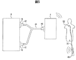
受信機4は、患者の遠位血圧に関する情報をモニタ6に伝える。遠位血圧を測定するには、圧力トランスデューサ52(図5に示す)を有するセンサ・ガイド・ワイヤの遠位端を、患者の体内、例えば、大腿動脈の開口部に挿入し、所望の位置に配置する。一実施形態では、圧力トランスデューサ52は、患者の冠状動脈内の狭窄より遠位の血圧を測定する。大動脈血圧及び遠位血圧の測定(及び、それに続く血流予備量比の計算)は、例えば、狭窄症の重度を診断する一つの手法である。送信機48はセンサ・ガイド・ワイヤ50に電気的に接続され、送信機48から無線で信号を受信するように構成された受信機4に血圧情報を無線で送信する(図5)。受信機4はモニタ6に接続され、モニタ6に血圧情報を送信する。一実施形態では、受信機4は、セント・ジュード・メディカル社(ST.JUDE MEDICAL)開発のプレッシャワイヤ・アエリス・レシーバー(PRESSUREWIRE AERIS RECEIVER)である。適切なセンサ・ガイド・ワイヤの1つが米国特許第8187195号に記載されており、これに記載される生理学的モニタリングに関連する構成要素、システム及び方法が参照により全てが本明細書に組み込まれる。
The receiver 4 communicates information about the patient's distal blood pressure to the monitor 6. To measure distal blood pressure, the distal end of a sensor guide wire having a pressure transducer 52 (shown in FIG. 5) is inserted into the patient's body, eg, an opening in the femoral artery, and placed in the desired location. Deploy. In one embodiment, the pressure transducer 52 measures blood pressure distal to the stenosis in the patient's coronary artery. Measurement of aortic blood pressure and distal blood pressure (and subsequent calculation of the reserve blood flow ratio) is one technique for diagnosing the severity of stenosis, for example. The
一部の種類のセンサ装置は、それらに接続されたモニタから電力供給を受ける。例えば、図1では、受信機4は、モニタ6から電力供給を受けることができる。しかし、ある種のモニタのチャネルは、受信機4などのセンサ装置に十分な電力を供給するように構成されておらず、センサ装置を意図通りに作動させることができない。これらのモニタは、BP22規格に準拠していないため、あるいは、センサ装置が必要とする電力がモニタの供給能力を超えるため、十分な電力を供給することができない。そこで、図2〜4に関連して説明する回路14の様々な実施形態では、モニタ6からセンサ装置への十分な電力供給を可能とする、センサ装置12とモニタ6間の接続を提供する。回路14は、センサ装置とモニタとを接続するケーブル内などにおいて、適切な形態のハードウェアで実施することができる。すなわち、本明細書に記載される回路14を含むケーブルは、センサ装置12とモニタ6間のインターフェースとして機能しており、センサ装置12は、モニタ6から十分な電力供給を受けることができる。
Some types of sensor devices receive power from monitors connected to them. For example, in FIG. 1, the receiver 4 can receive power from the monitor 6. However, certain types of monitor channels are not configured to supply sufficient power to a sensor device such as the receiver 4 and cannot operate the sensor device as intended. Since these monitors do not conform to the BP22 standard, or because the power required by the sensor device exceeds the supply capability of the monitor, sufficient power cannot be supplied. Thus, various embodiments of the
図2を参照すると、例示的な実施形態に係る回路図に、センサ装置12とモニタ6との間の電気的接続が示されている。センサ装置12は、ホイートストンブリッジ13を含んでもよい。従来、血圧トランスデューサは、ホイートストンブリッジ型回路構成に接続されたピエゾ抵抗素子に機械的に結合した感圧ダイヤフラムにより構成されている。ダイヤフラムが体腔(動脈や静脈系内など)と流体連通して配置されると、ダイヤフラムが圧力誘起によって歪み、抵抗素子が引き伸ばされる(又は、その方向によっては圧縮される)。周知の原理によれば、これは、印加された圧力に関連する形で素子の抵抗を変化させる。印加された圧力の大きさは、励起電力信号(通常、電圧の形態)をホイートストンブリッジ回路の入力に印加し、同時にブリッジ出力信号を監視することにより検知することができる。この信号の大きさは、オームの法則によれば、ブリッジ抵抗の変化量を反映している。
Referring to FIG. 2, an electrical connection between the
通常、電気ケーブルは、図1に示すように、トランスデューサセンサのホイートストンブリッジ部分と、モニタ6などの生体情報モニタ内のトランスデューサ増幅回路とを接続する。図2には、モニタ6のチャネル(例えば、ケーブルを介したセンサ装置への接続用)が、第1のチャネル16及び第2のチャネル18として示されている。モニタ6内の増幅回路は、励起出力信号をホイートストンブリッジに送信し、同時にブリッジ出力信号を監視する。励起電力信号は、通常は電圧の形態をしており、モニタの種類やメーカーによって、様々なレベルと形にすることができ、時間変化しても(正弦波、矩形波、パルス状)、時間非依存性(DC)でもよい。従来のホイートストンブリッジ・トランスデューサが動作する原理によれば、大部分の患者監視装置のトランスデューサ増幅回路は、励起電力信号の大きさに比例すると共に検知した圧力の大きさに比例する大きさのセンサ出力信号を想定して設計されている。
Normally, as shown in FIG. 1, the electric cable connects the Wheatstone bridge portion of the transducer sensor and a transducer amplification circuit in a biological information monitor such as the monitor 6. In FIG. 2, the channels of the monitor 6 (for example, for connection to a sensor device via a cable) are shown as a
図2を再び参照すると、回路14は、センサ装置12をモニタ(図1に示すモニタ6など)に接続している。回路14は、モニタ6の複数のポートに接続可能なケーブル内に設けることができる。センサ装置とモニタ間の従来の接続では、ケーブルは、センサ装置をモニタのたった1本のチャネルに接続している。一方、回路14を含むケーブル44又は他の物理インターフェースは、モニタ6の2本のチャンネルに接続している(図5参照)。このため、ケーブル44又は他の物理インターフェースは、図5に概略的に示す第1のコネクタ40と第2のコネクタ42を有している。第1のコネクタ40と第2のコネクタ42は、別々のハウジング内にあるものとして図示されているが、モニタ6への接続点を2箇所有する単一のハウジング内に収容することもできる。第1のコネクタ40は、モニタ6の第1のチャネル16に作動可能に結合することができ、モニタ6から励起電力信号を受信する。同様に、第2のコネクタ42は、第2のチャネル18に作動可能に結合することができ、モニタ6から別の励起電力信号を受信する。これらチャネルの少なくとも一方(例えば、第1のチャネル16)は、コネクタのうちの一方(例えば、第1のコネクタ40)を介してセンサ装置から測定された生理学的パラメータを表す信号を受信する。例えば、図2では、コネクタが第1のチャネル16に作動可能に結合され、(1)励起信号をモニタ6からセンサ装置12へ、及び(2)測定された生理学的パラメータを表す信号をセンサ装置12からモニタ6へ、送信可能としている。よって、回路14を含むケーブル44(図5)は、センサ装置12がモニタ6の、1本ではなく2本のチャネルから電力を得ることができるインターフェースとなっている。この機能により、1本のチャネルではセンサ装置12を十分に作動させる電力を供給できないモニタ6とセンサ装置12の併用(例えば、BP22規格に準拠していないモニタの使用又はモニタが供給できるよりも多くの電力を必要とするセンサ装置の使用)が可能となる。
Referring back to FIG. 2, the
上述したように、モニタ6は、第1のチャネル16と第2のチャネル18を含んでいる。図2の実施形態では、第1のチャネル16は、センサ装置12からの信号受信と、電圧形態の励起電力信号の送信の両方を行う。チャネル16、18により供給される電圧を、図2〜4では「Vex」と表している。圧力又は他の生理学的パラメータを表す信号をモニタ6に伝送する信号線を、図2〜4では「S」と表している。モニタ6の第2のチャネル18は、センサ装置12に追加の励起電力信号を送信する。モニタ6の第1のチャネル16と第2のチャネル18からの励起電力信号は、センサ装置12に供給される前に回路14内で合成される。モニタ6の2本のチャネルからの電力を合成することにより、回路14を含むケーブルは、1本のチャネルでは十分な電力を供給しえないモニタとセンサ装置12の併用を可能としている。一実施形態では、各チャネル16、18により供給される電力は、50mWである。センサ装置12が80mW必要とする場合、両チャネル16、18を使用することにより(合計100mWを供給)、十分な電力を得ることができる。
As described above, the monitor 6 includes the
回路14は、ノイズを抑えるために、1つ以上のフィルタ20a、20bを更に含む。フィルタは、受動フィルタでも、能動フィルタでも、他のタイプの適切なフィルタであってもよい。DC‐DCコンバータ22は、モニタ6からセンサ装置12に供給される電圧を再スケーリングする。一実施形態では、センサ装置12が作動するには、モニタ6からの供給より高電圧が必要となるため、電圧を再スケーリングする。一実施例において、各チャネル16、18が供給するのは2.5Vであり、センサ装置12が作動に必要とするのは4〜8Vで20mAである。よって、DC‐DCコンバータ22は、電圧を2.5Vから4〜8Vの間の電圧に上昇させる。一実施形態では、コンバータ22は、電圧を入力側の2.5Vから出力側の5.00Vに上昇させる電圧ダブラである。
The
センサ装置12が血圧などの1つ以上の生理学的パラメータを測定するために使用されると、測定された生理学的パラメータを表す信号がスケーリング回路24を介して伝達される。スケーリング回路24は、電圧を調節する。一実施形態では、スケーリング回路24は電圧を低減し、更に別の実施形態では、スケーリング回路24は分圧器である。スケーリング回路24は、抵抗器、又は、信号線S+及びS‐の間の電圧差を調整するその他の構成部品の組み合わせを含むことができる。モニタ6が、特定の電圧(例えば、2.5V)をセンサ装置12から受信するように構成されているため、スケーリング回路24により電圧が調節される。例えば、モニタ6を、1水銀柱ミリメートルごとに12.5mV受信するように構成してもよい。各チャネルからの供給が2.5Vであり、センサ装置の作動に4〜8Vを必要とする上述の例では、コンバータ22により、センサ装置12に供給される電圧が倍にされる。したがって、スケーリング回路24は、モニタ6が受信信号を生理的パラメータ測定値(例えば、血圧測定値)に正確に変換するように、電圧を半減させる。一実施形態では、モニタ6は、センサ装置12のインピーダンスが励起電圧(例えば、2.5V)を増加させないほどに十分高いことを前提としている。このように、モニタ6は、励起電圧(例えば、2.5V)に直接関連付けられた電圧の信号をセンサ装置12から受信することを想定している。センサ装置12が血圧を表す信号を返してくるように構成されている場合、モニタ6は、信号線S+及びS‐の間の電圧差を監視し、その差を対応する血圧値に変換する。センサ装置12に供給される電圧を再スケーリングし、その後帰還信号を調節することにより、回路14は、モニタ6が帰還信号を生理的パラメータ測定値(例えば、血圧測定値)に正確に変換できることを確実にしながら、センサ装置12(例えば、受信機4)に十分な電圧を供給することができるインターフェースとなっている。
When
図3を参照すると、回路図に、センサ装置12とモニタ6との間の電気的接続の追加の例示的実施形態が示される。図2の実施形態と同様に、回路14はセンサ装置12(ホイートストンブリッジ13を含む)とモニタ6との間のインターフェースとして機能する。回路14は、第1のチャネル16及び第2のチャネル18からの励起電力信号を合成してセンサ装置12に十分な電力を供給し、これにより、1本のチャネルでは十分な電力を提供しえないモニタとセンサ装置12の併用を可能としている。
Referring to FIG. 3, a circuit diagram shows an additional exemplary embodiment of the electrical connection between the
図3の回路14は、センサ装置12からモニタ6への信号を修正するスケーリング回路26を含む。スケーリング回路26は、センサ装置12からの信号を一定の感度にスケーリングする。一実施形態では、スケーリング回路26は、電圧制御増幅器28及びコンデンサ30を含むが、スケーリングに基準電圧を用いるADコンバータ−マイクロコントローラ−DAコンバータ構成などの他の回路が用いられてもよい。また、スケーリング回路26は、図2に関連して説明したスケーリング回路24と同じ機能を果たす構成要素も含む。つまり、スケーリング回路26は、信号を、特定のモニタ6に判断可能な電圧にスケーリングする。モニタ6に送られる信号をスケーリングする機能は、様々な構成要素を含む1つ以上のスケーリング回路を用いることにより達成することができる。
The
図3のスケーリング回路26が含まれていることにより、図2の実施形態にとはDC‐DCコンバータ22に関連する要件が変わる。図2の実施形態では、コンバータ22は、センサ装置12での使用に十分安定し、且つ、スケーリング回路24によりスケーリングされてモニタが正確な血圧値(又は別の生理的パラメータ値)となるように判断できるような電圧を供給しなければならない。つまり、図2の設計では(正確を期すため)、電圧ダブラが正確に(例えば、0.5%以内で)電圧を倍増させる必要がある。しかし、図3では、スケーリング回路26が存在するため、ホイートストンブリッジ13に印加される実際の電圧に応じてスケーリング回路26がセンサ装置12からの信号を調節することから、正確度の低い(又は安定度の低い)コンバータ22を用いることができる。信号は、モニタ6に送られる信号が、特定のモニタ6により正確に判断されるように、スケーリング回路26によってスケーリングされる。したがって、ホイートストンブリッジ13に印加される実際の電圧に基づいてスケーリングを行うスケーリング回路26が含まれていることにより、精度の低い(安価な)コンバータ22を用いることができる。
The inclusion of the scaling
図4は、センサ装置12とモニタ6との間の電気的接続の更に別の例示的実施形態を示す。本実施形態では、回路14により、利用者が(例えば、スイッチ32を介して)、モニタ6により受信される信号のスケーリングを一定の基準レベルに基づいて行うのか、第1及び第2のチャネル16、18からの励起電圧に基づいて行うのかを選択することができる。前述の実施形態と同様に、第1のチャネル16及び第2のチャネル18によって供給される励起出力信号は、図4の実施形態でも合成される。フィルタ20a、20bがノイズを除去する。図4では特定のフィルタの実施形態が示されているが、フィルタ20a、20bは、受動フィルタでも、能動フィルタでも、他のタイプの適切なフィルタであってもよい。一実施形態では、フィルタ20a、20bのうちの一方又は両方が、ローパスフィルタである。図4の実施形態では、DC‐DCコンバータ22を含み、入力電圧を再スケーリングする。一実施形態では、コンバータ22は電圧を上昇させ、更に別の実施形態では、コンバータ22は電圧を倍にする。目的の生理的パラメータ(例えば、血圧)を測定した後、センサ装置12は、測定されたパラメータを表す信号を第3のフィルタ20cへと送信する。フィルタ20cは、受動でも、能動でも、他のタイプの適切なフィルタであってもよい。一実施形態では、第3のフィルタ20cは、信号ノイズを低減する差動ローパスフィルタである。
FIG. 4 shows yet another exemplary embodiment of the electrical connection between the
図4のスケーリング回路24は、緩衝増幅器34を含む。緩衝増幅器34は、基準入力36を含む。スイッチ32により、利用者(又は製造業者)は、基準電圧源38により供給される一定の基準電圧とモニタ6により供給される励起電圧(例えば、交点19における)とで、基準入力36を切り替えることができる。スイッチ32が第1の位置(図4に示す位置)にあるとき、基準入力36は、基準電圧源38により一定の電圧を有する。しかし、スイッチ32が第2の位置に切り換えられると、基準入力36は、モニタ6により供給される励起電圧と等しい電圧を有することになる。ある種のモニタでは、センサ装置12から受信した信号の判断に、一定の基準を用いるように構成されている。これらモニタとセンサ装置12をインターフェース接続するために図4の回路14が使用される場合、スイッチは、モニタ6により受信される信号が一定の基準電圧に基づいてスケーリングされるように図4に示す位置でなければならない。一方、別のモニタでは、モニタにより供給される励起電圧を基準として用い、センサ装置12から受信した信号を判断するように構成されている。こういったシステムで図4の回路14を使用するためには、スイッチ32は、モニタから供給される励起信号を基準電圧として使ってセンサ装置12からの受信信号をスケーリングできる第2の位置になければならない。
The scaling
図5は、本明細書に記載の実施形態のいずれかに係る回路14を含むケーブル44の概略図を示す。上述したように、ケーブル44は、モニタ6の第1のチャネル16及び第2のチャネル18にそれぞれ作動可能に結合することができる第1のコネクタ40と第2のコネクタ42を含む。コネクタ40、42により、励起電力信号をケーブル44内に含まれる回路14を介してモニタ6からケーブル44に、そしてセンサ装置(受信機4など)へと送信することができる。更に、コネクタ40、42により、測定された生理学的変数を表す信号をセンサ機器から回路14を介してモニタ6に送信することができる。一実施形態では、測定された生理学的変数を表す信号は、コネクタ40を介してモニタ6に送信される。図5に示すように、ケーブル44は、第3のコネクタ46を更に含む。第3のコネクタ46は、受信機4などのセンサ装置に作動可能に結合することができ、モニタ6からセンサ装置に電力が伝送される。受信機4は、圧力トランスデューサ52を有するセンサ・ワイヤ50に接続された送信機48から、測定された血圧を表す情報を受信してもよい。一実施形態では、センサ・ワイヤ50は、セント・ジュード・メディカル社開発のプレッシャワイヤ・アエリス(商標)である。
FIG. 5 shows a schematic diagram of a
本明細書に記載の回路14を使用することによる利点がいくつかある。実際、回路14は、モニタからセンサ装置への十分な電力供給を可能とするインターフェースとなっている。この機能は、モニタがBP22規格に準拠していない場合、又は、モニタが供給できるよりも多くの電力をセンサ装置が必要とする場合に望ましい。回路14は、それぞれが励起電力信号を供給する利用可能なモニタのチャンネルを組み合わせ、接続されたセンサ装置が必要とする総電力と電圧を得ている。回路14は(例えば、図4に示す実施形態では)、スケーリング回路が柔軟に基準電圧を調節することにより、生理学的変数の正確な測定を可能にしている。また、回路14は、接続されたセンサ装置への電力供給を安定化させ、インターフェースに対するセンサ感度を標準化させることにより、センサ測定の精度を高めることができる。
There are several advantages to using the
様々な例示的な実施形態に示されるシステム及び方法の構成及び配置は、例示に過ぎない。本開示においては、ほんの一部の実施形態のみを詳細に説明してきたが、多くの変形例が可能である(例えば、様々な構成要素の構造、パラメータ値、装着配置、使用材料などの変更)。例えば、構成要素の位置を逆にする又は変更してもよく、また、個々の要素の性質や個数、又は位置を改める又は変更してもよい。従って、このような変更は全て本開示の範囲内に含まれることが意図される。全てのプロセス又は方法のステップは、代替の実施形態に従い、順序又は順番を変化させる、又は、順序を並べ直すことができる。その他の置き換え、修正、変更及び省略が、本開示の要旨を逸脱しない範囲で、例示的な実施形態の設計、動作条件及び配置で行うことができる。 The configurations and arrangements of the systems and methods illustrated in the various exemplary embodiments are merely exemplary. Although only a few embodiments have been described in detail in this disclosure, many variations are possible (eg, changes in various component structures, parameter values, mounting arrangements, materials used, etc.) . For example, the positions of the components may be reversed or changed, and the nature, number, or position of individual elements may be altered or changed. Accordingly, all such modifications are intended to be included within the scope of this disclosure. All process or method steps may be reordered or reordered according to alternative embodiments. Other substitutions, modifications, changes and omissions may be made in the design, operating conditions and arrangement of the exemplary embodiments without departing from the spirit of the present disclosure.
Claims (21)
生理学的モニタの第1のチャネルから第1の励起電力信号を供給されるように構成された第1のコネクタと、前記モニタの第2のチャネルから第2の励起電力信号を供給されるように構成された第2のコネクタとを備え、前記モニタの前記第1のチャネルからの前記第1の励起電力信号と前記第2のチャネルからの前記第2の励起電力信号は、前記ケーブルの内部で合成され合成電力信号を生成し、
前記合成電力信号を、測定した生理学的パラメータを表す情報を無線で受信し、前記測定した生理学的パラメータを表す信号を生成するように構成された受信機に供給するように構成された第3のコネクタと、
前記受信機に供給される前記合成電力信号の電圧を再スケーリングするように構成された電圧変換器と、を備え、
前記ケーブルは、前記受信機で生成した前記測定した生理学的パラメータを表す信号を受信するように構成され、前記測定した生理学的パラメータを表す信号の電圧を調節するように構成されたスケーリング回路をさらに備え、
前記ケーブルは、前記調節された信号を前記第1のコネクタ及び/又は前記第2のコネクタを介して前記モニタに送信するように構成されることを特徴とするケーブル。 A cable,
A first connector configured to be supplied with a first excitation power signal from a first channel of the physiological monitor, and a second excitation power signal from a second channel of the monitor; A second connector configured, wherein the first excitation power signal from the first channel of the monitor and the second excitation power signal from the second channel are internal to the cable. Combined to generate a combined power signal,
A third configured to wirelessly receive information representative of the measured physiological parameter and to provide the composite power signal to a receiver configured to generate a signal representative of the measured physiological parameter; A connector;
A voltage converter configured to rescale the voltage of the combined power signal supplied to the receiver;
The cable is further configured to receive a signal representative of the measured physiological parameter generated by the receiver, and further includes a scaling circuit configured to adjust a voltage of the signal representative of the measured physiological parameter. Prepared,
The cable is configured to transmit the adjusted signal to the monitor via the first connector and / or the second connector.
前記スイッチが前記第1の位置にあるとき、一定の基準電圧に基づいて、前記測定された生理学的パラメータを表す信号が前記スケーリング回路によりスケーリングされ、
前記スイッチが前記第2の位置にあるとき、前記モニタから供給される励起電圧に基づいて、前記測定された生理学的パラメータを表す信号が前記スケーリング回路によりスケーリングされる請求項10に記載のケーブル。 And further comprising a switch movable between the first position and the second position;
When the switch is in the first position, based on a constant reference voltage, a signal representative of the measured physiological parameter is scaled by the scaling circuit;
11. The cable of claim 10, wherein when the switch is in the second position, a signal representative of the measured physiological parameter is scaled by the scaling circuit based on an excitation voltage provided from the monitor.
ケーブルを用いて、前記ケーブルの第1のコネクタを介してモニタの第1のチャネルから受信した第1の励起電力信号と前記ケーブルの第2のコネクタを介して前記モニタの第2のチャネルから受信した第2の励起電力信号を合成して合成電力信号を生成することと、
前記ケーブルを用いて、前記合成電力信号の電圧を再スケーリングすることと、
前記ケーブルを用いて、前記再スケーリングした合成電力信号を前記ケーブルの第3のコネクタを介して前記受信機に送信することと、
前記受信機を用いて、測定した生理学的パラメータを表す情報を無線で受信し、前記測定した生理学的パラメータを表す信号を生成することと、
前記ケーブルを用いて、前記受信機で生成された前記測定した生理学的パラメータを表す情報を受信し、前記測定された生理学的パラメータを表す信号の電圧を調節することと、
前記ケーブルを用いて、前記ケーブルの前記第1のコネクタ及び/又は前記第2のコネクタを介して、前記測定された生理学的パラメータを表す信号を前記モニタに送信することを特徴とする、受信機を生理学的モニタに接続するインターフェースの作動方法。 A method of operating an interface connecting a receiver to a physiological monitor comprising:
Using a cable, the first excitation power signal received from the first channel of the monitor via the first connector of the cable and received from the second channel of the monitor via the second connector of the cable. Combining the generated second excitation power signal to generate a combined power signal;
Rescaling the voltage of the combined power signal using the cable;
Using the cable to transmit the rescaled combined power signal to the receiver via a third connector of the cable;
Using the receiver to wirelessly receive information representative of the measured physiological parameter and generate a signal representative of the measured physiological parameter;
Using the cable to receive information representative of the measured physiological parameter generated by the receiver and adjusting a voltage of a signal representative of the measured physiological parameter;
A receiver using the cable to transmit a signal representative of the measured physiological parameter to the monitor via the first connector and / or the second connector of the cable. Method of operating the interface to connect the to the physiological monitor.
前記スイッチが前記第1の位置にあるとき、一定の基準電圧に基づいて、前記測定された生理学的パラメータを表す信号の電圧が調節され、
前記スイッチが前記第2の位置にあるとき、前記モニタから供給される励起電圧に基づいて、前記測定された生理学的パラメータを表す信号の電圧が調節される請求項18に記載の方法。 The cable comprises a switch switchable between a first position and a second position;
When the switch is in the first position, a voltage of a signal representative of the measured physiological parameter is adjusted based on a constant reference voltage;
The method of claim 18, wherein when the switch is in the second position, a voltage of a signal representative of the measured physiological parameter is adjusted based on an excitation voltage provided from the monitor.
Applications Claiming Priority (3)
| Application Number | Priority Date | Filing Date | Title |
|---|---|---|---|
| US13/801,870 | 2013-03-13 | ||
| US13/801,870 US9325326B2 (en) | 2013-03-13 | 2013-03-13 | Interface and related method for connecting sensor equipment and a physiological monitor |
| PCT/IB2014/000979 WO2014140847A1 (en) | 2013-03-13 | 2014-03-11 | An interface and related method for connecting sensor equipment and a physiological monitor |
Related Child Applications (1)
| Application Number | Title | Priority Date | Filing Date |
|---|---|---|---|
| JP2017082992A Division JP2017144263A (en) | 2013-03-13 | 2017-04-19 | System for connecting sensor device and physiological monitor, cables, and method of connecting receiver |
Publications (2)
| Publication Number | Publication Date |
|---|---|
| JP2016512988A JP2016512988A (en) | 2016-05-12 |
| JP6285966B2 true JP6285966B2 (en) | 2018-02-28 |
Family
ID=50976998
Family Applications (2)
| Application Number | Title | Priority Date | Filing Date |
|---|---|---|---|
| JP2015559574A Active JP6285966B2 (en) | 2013-03-13 | 2014-03-11 | Method of operating an interface connecting a cable and a receiver to a physiological monitor |
| JP2017082992A Pending JP2017144263A (en) | 2013-03-13 | 2017-04-19 | System for connecting sensor device and physiological monitor, cables, and method of connecting receiver |
Family Applications After (1)
| Application Number | Title | Priority Date | Filing Date |
|---|---|---|---|
| JP2017082992A Pending JP2017144263A (en) | 2013-03-13 | 2017-04-19 | System for connecting sensor device and physiological monitor, cables, and method of connecting receiver |
Country Status (6)
| Country | Link |
|---|---|
| US (2) | US9325326B2 (en) |
| EP (1) | EP2967341B1 (en) |
| JP (2) | JP6285966B2 (en) |
| AU (1) | AU2014229608B2 (en) |
| CA (1) | CA2901911C (en) |
| WO (1) | WO2014140847A1 (en) |
Families Citing this family (3)
| Publication number | Priority date | Publication date | Assignee | Title |
|---|---|---|---|---|
| JP6466624B2 (en) | 2015-09-03 | 2019-02-06 | コーニンクレッカ フィリップス エヌ ヴェKoninklijke Philips N.V. | Cable unit for connecting devices and enabling wireless exchange of data and / or power between devices |
| CN110584628A (en) * | 2019-09-21 | 2019-12-20 | 为麦智能科技(天津)有限公司 | Vital sign acquisition device, unit and method |
| CN110584610B (en) * | 2019-09-21 | 2023-01-06 | 为麦智能科技(天津)有限公司 | Vital sign acquisition terminal and system |
Family Cites Families (6)
| Publication number | Priority date | Publication date | Assignee | Title |
|---|---|---|---|---|
| US5568815A (en) | 1994-11-21 | 1996-10-29 | Becton Dickinson And Company | Self-powered interface circuit for use with a transducer sensor |
| US8491503B2 (en) | 2004-09-29 | 2013-07-23 | Covidien Lp | Intrauterine pressure catheter interface cable system |
| US8187195B2 (en) * | 2005-10-12 | 2012-05-29 | Radi Medical Systems Ab | Sensor wire assembly |
| DE102007009573A1 (en) * | 2007-02-27 | 2008-09-04 | Up Management Gmbh & Co Med-Systems Kg | One-way sensor unit for patient observation, and arterial blood pressure sensor unit, has sensor provided around electrical quantity, which is based on quantity that has to be determined, and signal terminal that is provided around outlet |
| DE102010063482A1 (en) * | 2010-12-20 | 2012-06-21 | Karl Storz Gmbh & Co. Kg | Electrical cable for electrical energy and data transmission |
| US10772510B2 (en) * | 2012-08-22 | 2020-09-15 | Midmark Corporation | Vital signs monitor for controlling power-adjustable examination table |
-
2013
- 2013-03-13 US US13/801,870 patent/US9325326B2/en active Active
-
2014
- 2014-03-11 WO PCT/IB2014/000979 patent/WO2014140847A1/en active Application Filing
- 2014-03-11 JP JP2015559574A patent/JP6285966B2/en active Active
- 2014-03-11 AU AU2014229608A patent/AU2014229608B2/en active Active
- 2014-03-11 CA CA2901911A patent/CA2901911C/en active Active
- 2014-03-11 EP EP14731355.5A patent/EP2967341B1/en active Active
-
2016
- 2016-04-01 US US15/088,631 patent/US9584135B2/en active Active
-
2017
- 2017-04-19 JP JP2017082992A patent/JP2017144263A/en active Pending
Also Published As
| Publication number | Publication date |
|---|---|
| EP2967341A1 (en) | 2016-01-20 |
| AU2014229608A1 (en) | 2015-09-10 |
| CA2901911A1 (en) | 2014-09-18 |
| CA2901911C (en) | 2018-04-03 |
| US20140266380A1 (en) | 2014-09-18 |
| JP2017144263A (en) | 2017-08-24 |
| JP2016512988A (en) | 2016-05-12 |
| WO2014140847A1 (en) | 2014-09-18 |
| EP2967341B1 (en) | 2019-05-15 |
| US9584135B2 (en) | 2017-02-28 |
| AU2014229608B2 (en) | 2016-08-25 |
| US9325326B2 (en) | 2016-04-26 |
| US20160218720A1 (en) | 2016-07-28 |
Similar Documents
| Publication | Publication Date | Title |
|---|---|---|
| US10736573B2 (en) | Measurement system | |
| US8187195B2 (en) | Sensor wire assembly | |
| CN105658136B (en) | Patient monitor sensor type auto-configuration | |
| EP1774905B1 (en) | Sensor wire assembly | |
| JP2017144263A (en) | System for connecting sensor device and physiological monitor, cables, and method of connecting receiver | |
| US20170188954A1 (en) | Interface unit and a measurement system | |
| JP2007105459A (en) | Sensor/wire assembly | |
| US11234650B2 (en) | Measurement system |
Legal Events
| Date | Code | Title | Description |
|---|---|---|---|
| A131 | Notification of reasons for refusal |
Free format text: JAPANESE INTERMEDIATE CODE: A131 Effective date: 20160726 |
|
| A521 | Request for written amendment filed |
Free format text: JAPANESE INTERMEDIATE CODE: A523 Effective date: 20161025 |
|
| A02 | Decision of refusal |
Free format text: JAPANESE INTERMEDIATE CODE: A02 Effective date: 20161220 |
|
| A521 | Request for written amendment filed |
Free format text: JAPANESE INTERMEDIATE CODE: A523 Effective date: 20170419 |
|
| A911 | Transfer to examiner for re-examination before appeal (zenchi) |
Free format text: JAPANESE INTERMEDIATE CODE: A911 Effective date: 20170607 |
|
| A131 | Notification of reasons for refusal |
Free format text: JAPANESE INTERMEDIATE CODE: A131 Effective date: 20170829 |
|
| A521 | Request for written amendment filed |
Free format text: JAPANESE INTERMEDIATE CODE: A523 Effective date: 20171019 |
|
| TRDD | Decision of grant or rejection written | ||
| A01 | Written decision to grant a patent or to grant a registration (utility model) |
Free format text: JAPANESE INTERMEDIATE CODE: A01 Effective date: 20180109 |
|
| A61 | First payment of annual fees (during grant procedure) |
Free format text: JAPANESE INTERMEDIATE CODE: A61 Effective date: 20180202 |
|
| R150 | Certificate of patent or registration of utility model |
Ref document number: 6285966 Country of ref document: JP Free format text: JAPANESE INTERMEDIATE CODE: R150 |
|
| R250 | Receipt of annual fees |
Free format text: JAPANESE INTERMEDIATE CODE: R250 |
|
| R250 | Receipt of annual fees |
Free format text: JAPANESE INTERMEDIATE CODE: R250 |
|
| R250 | Receipt of annual fees |
Free format text: JAPANESE INTERMEDIATE CODE: R250 |
|
| R250 | Receipt of annual fees |
Free format text: JAPANESE INTERMEDIATE CODE: R250 |