JP6285657B2 - Image processing apparatus, image processing method, and program - Google Patents
Image processing apparatus, image processing method, and program Download PDFInfo
- Publication number
- JP6285657B2 JP6285657B2 JP2013158270A JP2013158270A JP6285657B2 JP 6285657 B2 JP6285657 B2 JP 6285657B2 JP 2013158270 A JP2013158270 A JP 2013158270A JP 2013158270 A JP2013158270 A JP 2013158270A JP 6285657 B2 JP6285657 B2 JP 6285657B2
- Authority
- JP
- Japan
- Prior art keywords
- image
- deformation
- coordinates
- range
- image processing
- Prior art date
- Legal status (The legal status is an assumption and is not a legal conclusion. Google has not performed a legal analysis and makes no representation as to the accuracy of the status listed.)
- Active
Links
Images


Description
本発明は、画像処理装置による表示対象画像の画像変形操作技術に関するものである。利用用途の一例としては、プロジェクタのキーストーン補正機能(または台形補正機能)として一般に知られる機能において、変形形状を操作するための技術に関するものである。 The present invention relates to an image transformation operation technique for a display target image by an image processing apparatus. An example of the usage is related to a technique for operating a deformed shape in a function generally known as a keystone correction function (or trapezoid correction function) of a projector.
画像処理装置においては、処理対象の画像に画像変形処理が必要とされる場合が多々ある。例えば、プロジェクタ製品においては、キーストーン(台形)補正処理と呼ばれる画像変形処理が行われている。具体的に説明すると、プロジェクタの出力光がスクリーンに投影されると、スクリーン上に投影される有効領域はプロジェクタの設置傾き角や光学的なレンズシフト等に起因して台形状に歪みが生じる。この台形状の歪みがあるままでは、ユーザにとって見づらいため、逆台形状に有効領域を画像変形し、スクリーン上に投影される有効領域が矩形状になるよう画像変形する処理が行われている。この画像変形処理は、キーストーン(台形)補正処理として一般に知られている。 In an image processing apparatus, there are many cases where an image transformation process is required for an image to be processed. For example, in a projector product, an image deformation process called a keystone (trapezoid) correction process is performed. More specifically, when the output light of the projector is projected on the screen, the effective area projected on the screen is distorted in a trapezoid shape due to the installation inclination angle of the projector, optical lens shift, and the like. Since it is difficult for the user to see this trapezoidal distortion, the effective area is deformed into an inverted trapezoidal shape, and the image is deformed so that the effective area projected on the screen is rectangular. This image deformation process is generally known as a keystone (trapezoid) correction process.
キーストーン補正処理をユーザが操作するための方法は、主に、プロジェクタ筐体のスクリーンに対する傾きを設定する方法(光学傾き指定方法)と、スクリーンに投影された画像の4隅の点の位置を移動させて設定する方法(4点指定変形方法)がある。 The method for the user to operate the keystone correction process is mainly to set the tilt of the projector housing with respect to the screen (optical tilt designation method) and the positions of the four corner points of the image projected on the screen. There is a method of moving and setting (four-point designating deformation method).
光学傾き指定方法は、プロジェクタ筐体の縦/横方向の傾きを設定するための入力装置を備え、プロジェクタは、入力装置を介して設定された縦/横方向の傾きの情報に基づいて、スクリーン上の光学歪みを逆補正するように変形処理を行う。 The optical tilt designation method includes an input device for setting the vertical / horizontal tilt of the projector housing, and the projector uses a screen based on the vertical / horizontal tilt information set via the input device. Deformation processing is performed so as to reversely correct the above optical distortion.
例えば、プロジェクタがスクリーンに対して上向きにあおり角度をもって設置されているときには、スクリーン上の投影面は上方向に広がる台形形状となる。このとき、ユーザは、光学傾き指定方法により縦方向の傾きをプロジェクタに設定し、プロジェクタは設定された縦方向の傾きにより生じる投影面のゆがみを打ち消す方向に変形を行う。 For example, when the projector is set upward with an angle with respect to the screen, the projection surface on the screen has a trapezoidal shape spreading upward. At this time, the user sets the tilt in the vertical direction to the projector by the optical tilt designation method, and the projector deforms in a direction to cancel the distortion of the projection plane caused by the set vertical tilt.
具体的には、スクリーンに対する上向きのあおり角度が入力されると、プロジェクタは入力画像を下方向に広がる台形形状に変形する。この結果、スクリーン上の投影画像は光学歪みが打ち消され、矩形状の形状として表示される。しかしながら、光学傾き指定方法は、スクリーン上の投影画像を矩形にすることはできるが、矩形にした投影画像をスクリーン枠に合わせるといった様にユーザの意図する位置に配置することができない。矩形にした投影画像をスクリーン枠に合わせるためには、光学傾き指定方法の他に、ズーム、レンズシフト等の操作がさらに必要になる。 Specifically, when an upward tilt angle with respect to the screen is input, the projector deforms the input image into a trapezoidal shape that spreads downward. As a result, the projected image on the screen is displayed as a rectangular shape with optical distortion canceled. However, the optical tilt designation method can make the projected image on the screen rectangular, but it cannot be placed at the position intended by the user, such as aligning the rectangular projected image with the screen frame. In order to match the rectangular projection image with the screen frame, operations such as zoom and lens shift are required in addition to the optical tilt designation method.
一方、4点指定変形方法は、スクリーン上の投影画像の4隅の座標をそれぞれ移動させて投影画像を変形させる方法であり、スクリーン上の投影画像を矩形に補正することに加え、光学傾き指定方法ではできない任意の位置への配置ができるという利点がある。 On the other hand, the four-point designating method is a method for transforming the projected image by moving the coordinates of the four corners of the projected image on the screen. In addition to correcting the projected image on the screen to a rectangle, the optical tilt is designated. There is an advantage that it can be arranged at any position that cannot be achieved by the method.
ところで、画像変形処理においては、実装構成に起因して、変形できる形状に制約が生じる。例えば、画像変形処理を行う方法の1つとして、画像を、まず、メモリに取り込んで、変形処理を加えてから出力する方法がある。この方法では、入力される画像の解像度及びメモリの容量によって変形できる形状の限界値が異なる。一般的には、解像度が高い程、メモリの使用量が多くなるので変形できる形状の限界値はより制限される。このため、4点指定変形方法においても変形できる形状の限界をユーザに通知するための構成が必要になる。 By the way, in the image deformation process, the shape that can be deformed is restricted due to the mounting configuration. For example, as one of the methods for performing image deformation processing, there is a method in which an image is first fetched into a memory, subjected to deformation processing, and then output. In this method, the limit value of the deformable shape varies depending on the resolution of the input image and the capacity of the memory. In general, the higher the resolution, the more memory is used, so the limit value of the shape that can be deformed is more limited. For this reason, a configuration for notifying the user of the limit of the shape that can be deformed even in the four-point designated deformation method is required.
この構成の一例としては、特許文献1の方法がある。特許文献1の方法では、4点指定変形方法において、スクリーン上の投影画像の4隅の内、ユーザが選択した頂点の移動可能な方向にマークを表示する。ここで、ユーザが選択した頂点が変形範囲の限界に位置していて所定の方向へ移動できない状態では、移動できない方向に対応する方向マークを目立たなくすることで変形できる形状の限界をユーザに通知する。 As an example of this configuration, there is a method disclosed in Patent Document 1. In the method of Patent Document 1, in the four-point designating modification method, marks are displayed in the movable direction of the vertex selected by the user among the four corners of the projected image on the screen. Here, when the vertex selected by the user is located at the limit of the deformation range and cannot move in a predetermined direction, the user is notified of the limit of the shape that can be deformed by making the direction mark corresponding to the direction that cannot be moved inconspicuous. To do.
ユーザが4点指定変形方法によって投影画像を変形させてスクリーン枠等の所定の位置に変形後の形状を配置しようとするとき、ユーザは投影画像を変形させてスクリーン枠に配置できるか否かを知る必要がある。 When the user attempts to deform the projected image by the four-point designated deformation method and place the deformed shape at a predetermined position such as a screen frame, the user determines whether the projected image can be deformed and placed on the screen frame. I need to know.
しかしながら、特許文献1に記載の方法では、選択した頂点を意図する形状にまで実際に移動してみなければ、ユーザの意図する形状に変形できるか否かが判らない。4頂点のいずれかが変形範囲の限界に達してしまいユーザの意図する形状にできなかった場合は、ユーザは該当の頂点を再調整しなおす必要があり、手戻りが発生してしまう。 However, in the method described in Patent Document 1, it is not possible to determine whether or not the selected vertex can be transformed into the shape intended by the user unless the selected vertex is actually moved to the intended shape. If any of the four vertices reaches the limit of the deformation range and cannot be formed into the shape intended by the user, the user needs to readjust the corresponding vertex and cause rework.
本発明は上記の課題を解決するためになされたものであり、投影画像の変形可能範囲を変形前に提示して、効率的な画像変形操作を実現することを目的とする。 The present invention has been made to solve the above-described problems, and an object of the present invention is to provide an efficient image deformation operation by presenting a deformable range of a projected image before the deformation.
上記の目的を達成するための本発明による画像処理装置は以下の構成を備える。即ち、
入力画像から変形画像を生成するための変形処理を実行する変形手段と、
前記入力画像の座標を指定する指定手段と、
前記指定手段により指定された座標の前記変形手段による変形処理に基づく移動可能範囲を示す範囲画像を、前記指定された座標と前記入力画像の他の座標との位置関係に基づいて生成する生成手段と、
前記生成手段により生成された範囲画像を投影手段に投影させる投影制御手段と、
を有する。
In order to achieve the above object, an image processing apparatus according to the present invention comprises the following arrangement. That is,
Deformation means for executing deformation processing for generating a deformation image from an input image;
Designating means for designating the coordinates of the input image;
Generating means for generating a range image indicating a movable range based on deformation processing by the deforming means of the coordinates specified by the specifying means based on a positional relationship between the specified coordinates and other coordinates of the input image. When,
Projection control means for projecting the range image generated by the generating means onto the projecting means;
Have
本発明によれば、投影画像の変形可能範囲を変形前に提示して、効率的な画像変形操作を実現できる。 According to the present invention, the deformable range of the projected image is presented before the deformation, and an efficient image deformation operation can be realized.
以下、本発明の実施の形態について図面を用いて詳細に説明する。 Hereinafter, embodiments of the present invention will be described in detail with reference to the drawings.
<実施形態1>
図1は実施形態1の画像処理装置の1つである画像変形装置の機能構成を示す図である。尚、図1の画像変形装置101は、汎用コンピュータに搭載される標準的な構成要素(例えば、CPU、RAM、ROM、ハードディスク、外部記憶装置、ネットワークインタフェース、ディスプレイ、キーボード、マウス等)を有している。そして、これらの構成要素によって、図1に示す画像変形装置101の各種機能構成要素を実現する。
<Embodiment 1>
FIG. 1 is a diagram illustrating a functional configuration of an image transformation apparatus that is one of the image processing apparatuses according to the first embodiment. 1 has standard components (for example, CPU, RAM, ROM, hard disk, external storage device, network interface, display, keyboard, mouse, etc.) mounted on a general-purpose computer. ing. These constituent elements realize various functional constituent elements of the image deformation apparatus 101 shown in FIG.
図1の画像変形装置101は、投影面への投影対象となる入力画像100を変形し、かつその変形形状において4隅の各頂点をどこまで変形させることができるかという情報を重畳し、出力画像102を生成する。尚、以降の説明において、実施形態1では、ユーザが画像の変形指示を行うために操作する基準となる、入力画像上の点として、例えば、その画像の4隅の各頂点のことを「代表点」、ユーザが選択した頂点のことを「選択された代表点」とそれぞれ記載する。また、図1に示す変形能力情報113、代表点選択情報114、変形制御情報115、代表点情報116及び変形可能範囲情報117の各情報の詳細データ構造を図2に示し、併せて説明する。
The image deforming apparatus 101 in FIG. 1 superimposes information indicating how much the vertexes of the four corners can be deformed in the deformed shape by deforming the
以降、画像変形装置101の構成について詳細に説明する。画像変形装置101に入力された入力画像100は画像変形部104に入力される。画像変形部104は入力画像100と変形制御情報115を入力とし、メモリ103との間で画像データ111の読み書きを行って変形画像112と変形能力情報113とを出力する。ここで、変形制御情報115は、図2に示すとおり、変形前の代表点座標と、それに対応する変形後の代表点座標の4つの組から構成される情報であり、変形前後の座標の関係を示している。実施形態1では、入力画像100の4頂点を代表点としているので、変形前の代表点座標は入力画像100の矩形の4頂点の座標である。
Hereinafter, the configuration of the image deformation device 101 will be described in detail. The
尚、この座標は、例えば、投影面であるスクリーン上の所定点(原点)を基準に定義されるスクリーン座標系における座標であっても良いし、画像変形装置101において、仮想的に定義される仮想座標系における座標であっても良い。いずれにしても、画像変形処理において、統一的に扱うことができる座標系を予め定義しておき、その座標系に従って画像変形処理を実現することができればよい。この座標系とは、例えば、X軸及びY軸で規定される2次元の座標系を意味する。本実施形態では、水平方向をX軸、垂直方向をY軸とするスクリーン座標系を例にとって説明する。 The coordinates may be coordinates in a screen coordinate system defined on the basis of a predetermined point (origin) on the screen as a projection plane, or are virtually defined in the image transformation apparatus 101. Coordinates in a virtual coordinate system may be used. In any case, it is only necessary to previously define a coordinate system that can be handled uniformly in the image deformation process and to realize the image deformation process according to the coordinate system. This coordinate system means, for example, a two-dimensional coordinate system defined by the X axis and the Y axis. In this embodiment, a screen coordinate system in which the horizontal direction is the X axis and the vertical direction is the Y axis will be described as an example.
画像変形部104は、変形制御情報115で指定される変形の通りに入力画像100を変形しながらメモリ103に書き込み、メモリ103上の変形画像の完成したラインから読出を行って変形画像112を出力する。それに加え、画像変形部104は各代表点の変形可能範囲を生成するために必要となる、画像変形部104の画像変形能力を示す変形能力情報113を出力する。変形能力情報113としては、画像変形部104の実装によっていくつかの例が挙げられるが、ここでは、図2に示すように、最大傾き情報を使用する例を示す。
The image transformation unit 104 writes the
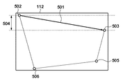
ここで、画像変形部104からメモリ103に書き込まれる画像データ111の関係を図3に示す。図3に示すように、入力画像100の1ライン目が画像変形部104に入力されると、代表点502と代表点503を結ぶアドレスに沿って、入力画像の1ライン分の入力に相当するメモリ書込501が発生する。このため、メモリ103は、図3に示すような、メモリ103に保持するライン数504に相当する容量のデータを保持する必要がある。通常は、画像変形装置101を設計する際にメモリ103の容量が決められるため、メモリに保持するライン数504には上限があり、各代表点の関係はこの上限に収まるようにしなければならない。
Here, the relationship between the image data 111 written in the memory 103 from the image transformation unit 104 is shown in FIG. As shown in FIG. 3, when the first line of the
尚、キーストーン変形においては、入力画像の1ライン分の入力に相当するメモリ書込における代表点を結ぶ直線の傾きは、変形後の四角形の上辺か下辺かのいずれかが最大の傾きとなる。つまり、代表点502と代表点503を結ぶ直線、代表点506と代表点505を結ぶ直線のいずれかの傾きが傾き最大となるので、この2つの傾きが共に変形能力情報113の最大傾き情報で指定される傾き以下となる必要がある。このことを制御部としても機能する変形可能範囲生成部107に対して通知するために、画像変形部104は変形能力情報113を出力する。
In the keystone deformation, the inclination of the straight line connecting the representative points in memory writing corresponding to the input of one line of the input image has the maximum inclination on either the upper side or the lower side of the deformed square. . That is, since the gradient of either the straight line connecting the
次に、代表点生成部105は、入力画像100を入力として代表点情報116を出力する。ここで、代表点情報116はユーザが変形形状を制御するための情報であり、図2に示すとおり、複数の代表点の情報から構成され、さらに各々の代表点の情報は現在の座標から構成される。ユーザは、代表点情報116で示される代表点を選択及び移動させることで変形形状を制御する。代表点生成部105は入力画像100を入力とし、入力画像100のサイズから代表点情報116を生成する。実施形態1のキーストーン変形の4点指定変形方法においては、代表点生成部105は代表点情報116として入力画像100の4頂点を出力する。
Next, the representative point generation unit 105 receives the
次に、代表点操作部106は、ユーザによる変形制御を行うものであり、代表点情報116と変形可能範囲情報117を入力とし、代表点選択情報114と変形制御情報115を出力する。
Next, the representative point operation unit 106 performs deformation control by the user, receives the
次に、変形可能範囲生成部107は、代表点情報116と変形能力情報113と代表点選択情報114を入力として、変形可能範囲情報117を生成する。ここで、代表点選択情報114とは、代表点情報116の内、ユーザによって選択された代表点を示す情報である。さらに、代表点選択情報114は、図2に示すとおり、複数の選択された代表点の情報から構成され、さらに各々の選択された代表点の情報は、該代表点に対応する現在の座標から構成される。また、変形可能範囲情報117は、図2に示すとおり、複数の選択された代表点の情報から成る。また、各々の選択された代表点の情報は、各々の選択された代表点に対応する座標と変形可否判定結果の情報から成る。
Next, the deformable range generation unit 107 receives the
尚、変形可否判定結果は、選択された代表点が該座標において変形できるか否かを示す2値の情報とする。変形可能範囲情報117は、ユーザによって選択された代表点が、投影面上のどの範囲まで移動可能であるかを示す情報(移動可能範囲)である。キーストーン変形の4点指定変形方法においてユーザが1つの代表点を選択して変形指示を行う際には、変形可能範囲情報117は1つの選択された代表点情報から成り、該代表点の現在の座標周辺の座標における変形可否判定結果の情報を有する。
The deformability determination result is binary information indicating whether the selected representative point can be deformed at the coordinates. The
ここで、変形可能範囲生成部107の処理を図4の処理フローを用いて具体的に説明する。変形可能範囲生成部107は、処理を開始すると、全ての選択された代表点に繰り返すループに入る(ステップS201)。例として、キーストーン変形の4点指定変形方法において、ユーザが右下の代表点を選択するような場合には、選択された代表点は1つであり、ステップS201は1重のループとなる。 Here, the processing of the deformable range generation unit 107 will be specifically described with reference to the processing flow of FIG. When the process starts, the deformable range generator 107 enters a loop that repeats for all selected representative points (step S201). As an example, when the user selects the lower right representative point in the four-point specified deformation method of keystone deformation, there is one selected representative point, and step S201 becomes a single loop. .
次に、変形可能範囲生成部107は、ステップS201で処理対象として選択された代表点を可動点(操作可能にする代表点)に設定する(ステップS202)。次に、変形可能範囲生成部107は、その可動点に対して、スクリーン座標系(XY座標系)において、X,Y方向に繰り返すループ処理を行う(ステップS203)。ここで、X、Y方向に繰り返すループ処理とは、選択された代表点を中心として±dX、±dYの範囲を可動点の座標範囲とする処理を意味する。ここで、dX,dYは選択した代表点と隣接する代表点との中間点もしくは、選択した代表点とX,Y方向の最も近い表示端までのX・Y座標距離の、大きい値をとる。このループ処理の中では、変形可能範囲生成部107は、可動点の座標を、X,Y方向に繰り返すループで指定される座標に設定する(ステップS204)。 Next, the deformable range generation unit 107 sets the representative point selected as the processing target in step S201 as a movable point (a representative point that can be operated) (step S202). Next, the deformable range generation unit 107 performs a loop process repeated in the X and Y directions on the movable point in the screen coordinate system (XY coordinate system) (step S203). Here, the loop process that repeats in the X and Y directions means a process in which the range of ± dX, ± dY around the selected representative point is used as the coordinate range of the movable point. Here, dX and dY take a large value of the X / Y coordinate distance between the selected representative point and an adjacent representative point or the closest representative display point in the X and Y directions with the selected representative point. In this loop process, the deformable range generating unit 107 sets the coordinates of the movable point to the coordinates specified by the loop that repeats in the X and Y directions (step S204).
次に、変形可能範囲生成部107は、可動点以外の座標を、現在の代表点の座標に設定する(ステップS205)。ここまでの処理で、選択された代表点の中の1つが可動点として任意の座標に決定され、その他の代表点も同様に現在の代表点の座標に決定され、全ての代表点の座標が決定される。 Next, the deformable range generation unit 107 sets coordinates other than the movable point to the coordinates of the current representative point (step S205). In the processing so far, one of the selected representative points is determined as an arbitrary coordinate as a movable point, the other representative points are similarly determined as the coordinates of the current representative point, and the coordinates of all the representative points are determined. It is determined.
次に、変形可能範囲生成部107は、決定された代表点で指定される形状に対して変形可能であるか否かの判定処理を行う(ステップS206)。実施形態1では、変形能力情報113は最大傾き情報としているので、可動点と隣接する代表点との傾きが、変形能力情報113が示す最大傾きを超えるかどうかで判定する。このように、変形可能であるか否かの判定処理は、可動点である選択された代表点とそれ以外の固定の代表点との位置関係に基づいて行う。
Next, the deformable range generation unit 107 performs a process of determining whether or not the shape specified by the determined representative point can be deformed (step S206). In the first embodiment, since the
次に、変形可能範囲生成部107は、この可動点の座標と、変形可否判定結果を記録する(ステップS207)。これらのループ処理を完了した後、全ての選択された代表点に対応する可動点の座標と、変形可否判定結果を変形可能範囲情報117として出力する(ステップS208)。以上で、変形可能範囲生成部107による処理が終了する。 Next, the deformable range generation unit 107 records the coordinates of the movable point and the deformability determination result (step S207). After completing these loop processes, the coordinates of the movable points corresponding to all selected representative points and the deformability determination result are output as deformable range information 117 (step S208). Above, the process by the deformable range production | generation part 107 is complete | finished.
この説明の例では、キーストーン変形の4点指定変形方法においてユーザが1つの代表点を選択する場合を説明している。ここで、初期状態として4つの代表点を選択する場合には、全ての選択された代表点に繰り返すループ(ステップS201)が4回繰り返される。この結果、4つの代表点に対して変形可能範囲情報117が生成され、ユーザが代表点を選択する前から4つの代表点の全てに対して変形可能範囲を表示するという処理も可能である。
In the example of this explanation, a case is described in which the user selects one representative point in the four-point designating transformation method of keystone transformation. Here, when four representative points are selected as the initial state, a loop (step S201) that repeats for all selected representative points is repeated four times. As a result, the
図1の説明に戻る。 Returning to the description of FIG.
次に、変形可能範囲描画部108は、代表点情報116と代表点選択情報114と変形可能範囲情報117を入力とし、それらの入力情報を描画した変形可能範囲画像118を出力する。入出力の関係を、図2と図5を用いてより詳細に説明する。入力とする各情報の代表点情報116、代表点選択情報114及び変形可能範囲情報117はそれぞれ図2に示したとおりである。これに対して、出力の変形可能範囲画像118の一例を図5に示す。ここでは、変形可能範囲描画部108の処理を図2と図5を用いて詳細に説明する。
Next, the deformable range drawing unit 108 receives the
変形可能範囲描画部108は、代表点情報116の内、代表点選択情報114に含まれない代表点を描画する。キーストーン変形の4点指定変形方法においてユーザが右下の代表点(図5では、代表点407)を選択していれば、図5の変形可能範囲画像118に示すとおり、代表点404、405及び406が描画される。次に、変形可能範囲描画部108は、代表点選択情報114に含まれる代表点を描画する。図5の場合では、変形可能範囲画像118において、選択された代表点407が描画される。次に、変形可能範囲描画部108は、変形可能範囲情報117で示される領域(変形可能範囲)を描画する。この例においては、図5の変形可能範囲画像118において、選択された代表点407に対する変形可能範囲408の領域が描画され、変形可能範囲描画部108の処理が完了する。
The deformable range drawing unit 108 draws representative points that are not included in the representative
尚、変形可能範囲情報117に含まれる変形可否判定結果が選択された代表点407による変形が不可能であることを示している場合には、変形可能範囲画像118に代えて、その旨を示す所定の画像(例えば、メッセージ画像)を表示する。
When the deformability determination result included in the
次に、画像合成部109は、変形可能範囲画像118と変形画像112を入力とし、それらを合成した出力画像102を出力する。この処理を図5を用いて具体的に説明する。変形可能範囲画像118と変形画像112の2つの例は、図5に示すとおりであり、変形画像112の上に変形可能範囲画像118を半透明合成することで出力画像102を出力する。但し、画像合成の方法は半透明合成に限らず、出力画像102において変形可能範囲画像118が識別できればよく、変形可能範囲画像118を重畳するような合成処理であってもよい。
Next, the image composition unit 109 receives the
以上説明したように、実施形態1によれば、画像変形装置101は、ユーザの選択した代表点407の変形可能範囲408を含む変形可能範囲画像118を変形画像112に合成して出力画像102として出力する。これにより、出力画像102において、ユーザの意図する変形形状が実現できるか否かを予め通知する。これにより、従来技術の課題であった、選択した頂点を意図する形状にまで実際に移動してみなければ、ユーザの意図する形状に変形できるか否かが判らないという課題が解消され、ユーザは意図する変形形状が実現できるか否かを予め知ることが可能になる。
As described above, according to the first embodiment, the image deformation device 101 combines the
このように、ユーザが4点指定変形方法によって投影画像を変形させてスクリーン枠等の所定の位置に変形後の形状を配置しようとする時、ユーザは投影画像を変形させてスクリーン枠に配置できるか否かを、変形を行う前に知ることが可能になる。より具体的には、4点指定変形方法の変形操作を行うための4頂点のいずれかを選択した時点で、選択された頂点の変形可能範囲を知ることができる。 In this way, when the user attempts to deform the projected image by the four-point designated deformation method and place the deformed shape at a predetermined position such as a screen frame, the user can deform the projected image and place it on the screen frame. It becomes possible to know whether or not the transformation is performed. More specifically, when one of the four vertices for performing the deformation operation of the four-point specified deformation method is selected, the deformable range of the selected vertex can be known.
<実施形態2>
実施形態2では、ユーザの選択した代表点の変形可能範囲の情報に加え、代表点を変形可能範囲内で移動させたときの画像品位をユーザに通知することを目的とする。画像変形処理においては、画像の拡大によるジャギーの発生や縮小による画像の潰れによる画質の画像劣化が発生する。これらの画像劣化は変倍率(拡大率または縮小率)が等倍から離れている領域で顕著に起こるため、変形後の画像は等倍に近い方が画質としては望ましい。このため、実施形態2では、選択された代表点の変形可能範囲における画像品位を示す情報、変形後の画像の変倍率(拡大率及び縮小率)をもとに生成して出力する。
<
The second embodiment aims to notify the user of the image quality when the representative point is moved within the deformable range, in addition to the information of the deformable range of the representative point selected by the user. In the image transformation process, image quality deterioration due to generation of jaggies due to image enlargement or image collapse due to reduction occurs. Since these image degradations occur remarkably in a region where the variable magnification (enlargement ratio or reduction ratio) is away from the same magnification, it is desirable for the image quality after deformation to be closer to the same magnification. For this reason, in the second embodiment, the image is generated and output based on the information indicating the image quality in the deformable range of the selected representative point and the scaling factor (enlargement ratio and reduction ratio) of the image after deformation.
上述のことを実現するために、実施形態2は、実施形態1において変形可能範囲生成部107と変形可能範囲描画部108の処理が異なる。まず、変形可能範囲生成部107では、図4のフローチャートにおける変形可能であるか否かの判定処理(ステップS206)において、画像品位情報を生成する処理を更に行う。画像品位情報は変形後の画像の最大倍率及び最小倍率とから以下の計算で算出する。 In order to realize the above, the second embodiment is different in the processes of the deformable range generation unit 107 and the deformable range drawing unit 108 in the first embodiment. First, the deformable range generation unit 107 further performs processing for generating image quality information in the determination processing (step S206) of whether or not deformation is possible in the flowchart of FIG. The image quality information is calculated by the following calculation from the maximum magnification and the minimum magnification of the deformed image.
MAX(最大倍率 − 1.0,1.0 − 最小倍率)
尚、ここでMAX()関数は引数の内、大きい方の値を返す関数とする。この式では等倍(1.0)と最大倍率及び最小倍率との差の絶対値の内、大きい方を得ることを目的とする。これは変形により拡大または縮小が発生するが、より等倍から離れている方が画像品位の低下が大きいであろうという考えに基づいている。仮に、最大倍率が1.1(110%)、最小倍率が0.8(80%)である場合には、0.2(=MAX(1.1−1.0,1.0−0.8))が得られる。
MAX (Maximum magnification-1.0, 1.0-Minimum magnification)
Here, the MAX () function is a function that returns the larger value of the arguments. The purpose of this equation is to obtain the larger one of the absolute values of the difference between the same magnification (1.0) and the maximum magnification and the minimum magnification. This is based on the idea that although the enlargement or reduction occurs due to the deformation, the image quality is likely to be lowered more distant from the same magnification. If the maximum magnification is 1.1 (110%) and the minimum magnification is 0.8 (80%), then 0.2 (= MAX (1.1-1.0, 1.0-0. 8)) is obtained.
上述の値を、予め規定しておいた画像品位情報との対応付けを行い、画像品位情報を出力する。具体的例としては、0.0〜0.1を画像品位:良、0.1〜0.2を画像品位:中、0.2〜を画像品位:低とする。但し、対応付けは必ずしもこのとおりではなく、等倍に近い方を画像品位が良く、等倍から遠い方を画像品位が低いと対応付ける。こうして生成した画像品位情報を、変形可能範囲情報117に加えて出力する。
The above-described value is associated with image quality information defined in advance, and image quality information is output. As a specific example, 0.0 to 0.1 is image quality: good, 0.1 to 0.2 is image quality: medium, and 0.2 to is image quality: low. However, the association is not necessarily as described above, and the image quality that is close to the same magnification is good and the image quality that is far from the normal magnification is associated with low image quality. The image quality information generated in this way is output in addition to the
次に、変形可能範囲描画部108は、画像品位情報を含む変形可能範囲情報117を用いて変形可能範囲画像118を描画する。具体例を図6に示す。図6の変形可能範囲画像118では、選択された代表点604の変形可能範囲に加え、画像品位情報が画像品位「良」の範囲605、画像品位「中」の範囲606、画像品位「低」の範囲607として出力される。こうして生成された変形可能範囲画像118が、画像合成部109において変形画像112と合成されて出力され、出力画像102が生成される。
Next, the deformable range drawing unit 108 draws the
以上説明したように、実施形態2によれば、画像変形装置101はユーザの選択した代表点の変形可能範囲の情報に加え、画像品位をユーザに通知することが可能になる。これにより、ユーザは実際に変形操作を行う前に、選択した頂点を任意の位置に移動させた時の画像品位の低下の度合いを予め知ることが可能になる。 As described above, according to the second embodiment, the image deformation device 101 can notify the user of the image quality in addition to the information on the deformable range of the representative point selected by the user. Thus, the user can know in advance the degree of degradation in image quality when the selected vertex is moved to an arbitrary position before actually performing the deformation operation.
つまり、ユーザは、4点指定変形方法の変形操作を行うための4頂点のいずれかを選択した時点で、その選択した点を操作して変形指定したときの画像品位を知ることができる。 That is, when the user selects any of the four vertices for performing the deformation operation of the four-point specifying deformation method, the user can know the image quality when the selected point is operated and the deformation is specified.
尚、本発明は、以下の処理を実行することによっても実現される。即ち、上述した実施形態の機能を実現するソフトウェア(プログラム)を、ネットワーク又は各種記憶媒体を介してシステムまたは装置に供給し、そのシステムまたは装置のコンピュータ(またはCPUやMPU等)がプログラムを読み出して実行する処理である。 The present invention can also be realized by executing the following processing. That is, software (program) that realizes the functions of the above-described embodiments is supplied to a system or apparatus via a network or various storage media, and a computer (or CPU, MPU, or the like) of the system or apparatus reads the program. It is a process to be executed.
Claims (14)
前記入力画像の座標を指定する指定手段と、
前記指定手段により指定された座標の前記変形手段による変形処理に基づく移動可能範囲を示す範囲画像を、前記指定された座標と前記入力画像の他の座標との位置関係に基づいて生成する生成手段と、
前記生成手段により生成された範囲画像を投影手段に投影させる投影制御手段と、
を有することを特徴とする画像処理装置。 Deformation means for executing deformation processing for generating a deformation image from an input image;
Designating means for designating the coordinates of the input image;
Generating generated based on the positional relationship between the other coordinates of the range image showing the movable range due to the deformation processing by the deformation means of the designated coordinates, and the designated coordinate the input image by the specifying means Means,
Projection control means for projecting the range image generated by the generating means onto the projecting means;
An image processing apparatus comprising:
前記生成手段は、前記指定された頂点と、残りの頂点の少なくとも1つとの位置関係に基づいて前記範囲画像を生成することを特徴とする請求項1乃至5のうち、何れか1項に記載の画像処理装置。The said production | generation means produces | generates the said range image based on the positional relationship of the said designated vertex and at least one of the remaining vertices, The any one of Claims 1 thru | or 5 characterized by the above-mentioned. Image processing apparatus.
前記生成手段は、前記特定手段により特定された画像品位を示す情報を含む前記範囲画像を生成することを特徴とする請求項1乃至7のうち、何れか1項に記載の画像処理装置。 A specifying means for specifying the image quality after the deformation process based on a scaling factor due to the deformation of the input image;
Said generating means, among the claims 1 to 7, characterized in that to generate the range image including information indicating the image quality specified by the specifying unit, an image processing apparatus according to any one.
前記入力画像の座標の指定を受け付ける受付工程と、
前記受付工程により受け付けられた座標の前記変形手段による変形処理に基づく移動可能範囲を示すための範囲画像を、前記指定された座標と前記入力画像の他の座標との位置関係に基づいて生成する生成工程と、
前記生成工程により生成された範囲画像を投影手段に投影させる投影制御工程と、
を有することを特徴とする画像処理方法。 An image processing method by an image processing apparatus having deformation means for executing deformation processing for generating a deformation image from an input image,
An accepting step of accepting designation of coordinates of the input image;
A range image for indicating a movable range based on the deformation process by the deformation unit of the coordinates received in the reception step is generated based on a positional relationship between the designated coordinates and other coordinates of the input image. Generation process;
A projection control step of causing the projection means to project the range image generated by the generation step;
An image processing method comprising:
前記生成工程においては、前記指定された頂点と、残りの頂点の少なくとも1つとの位置関係に基づいて前記範囲画像が生成されることを特徴とする請求項10乃至12のうち、何れか1項に記載の画像処理方法。The range image is generated in the generation step based on a positional relationship between the designated vertex and at least one of the remaining vertices. An image processing method described in 1.
Priority Applications (1)
| Application Number | Priority Date | Filing Date | Title |
|---|---|---|---|
| JP2013158270A JP6285657B2 (en) | 2013-07-30 | 2013-07-30 | Image processing apparatus, image processing method, and program |
Applications Claiming Priority (1)
| Application Number | Priority Date | Filing Date | Title |
|---|---|---|---|
| JP2013158270A JP6285657B2 (en) | 2013-07-30 | 2013-07-30 | Image processing apparatus, image processing method, and program |
Publications (3)
| Publication Number | Publication Date |
|---|---|
| JP2015029226A JP2015029226A (en) | 2015-02-12 |
| JP2015029226A5 JP2015029226A5 (en) | 2016-09-08 |
| JP6285657B2 true JP6285657B2 (en) | 2018-02-28 |
Family
ID=52492664
Family Applications (1)
| Application Number | Title | Priority Date | Filing Date |
|---|---|---|---|
| JP2013158270A Active JP6285657B2 (en) | 2013-07-30 | 2013-07-30 | Image processing apparatus, image processing method, and program |
Country Status (1)
| Country | Link |
|---|---|
| JP (1) | JP6285657B2 (en) |
Families Citing this family (1)
| Publication number | Priority date | Publication date | Assignee | Title |
|---|---|---|---|---|
| JP2018113519A (en) * | 2017-01-10 | 2018-07-19 | キヤノン株式会社 | Projection device and projection method |
Family Cites Families (6)
| Publication number | Priority date | Publication date | Assignee | Title |
|---|---|---|---|---|
| JP3541845B1 (en) * | 2003-02-17 | 2004-07-14 | セイコーエプソン株式会社 | Image correction method for projector and projector |
| JP2006174499A (en) * | 2006-01-12 | 2006-06-29 | Sanyo Electric Co Ltd | Liquid crystal projector |
| JP4688768B2 (en) * | 2006-09-26 | 2011-05-25 | シャープ株式会社 | Image adjustment method and projector |
| JP5194976B2 (en) * | 2008-04-11 | 2013-05-08 | セイコーエプソン株式会社 | Projector and control method thereof |
| JP5386883B2 (en) * | 2008-08-20 | 2014-01-15 | セイコーエプソン株式会社 | Projector and projector control method |
| JP5441672B2 (en) * | 2009-12-25 | 2014-03-12 | キヤノン株式会社 | Projection display |
-
2013
- 2013-07-30 JP JP2013158270A patent/JP6285657B2/en active Active
Also Published As
| Publication number | Publication date |
|---|---|
| JP2015029226A (en) | 2015-02-12 |
Similar Documents
| Publication | Publication Date | Title |
|---|---|---|
| JP6568223B2 (en) | Projection device, projection method, and projection program | |
| CN107403409B (en) | Image processing method and device before image splicing and image splicing method and device | |
| US10325345B2 (en) | Device for performing image transformation processing and method thereof | |
| JP4688768B2 (en) | Image adjustment method and projector | |
| US20220141436A1 (en) | Projection device and projection image correction method thereof | |
| CN104079907B (en) | Projector, image correcting method | |
| JP2013101525A (en) | Image processing device, method, and program | |
| JP5832119B2 (en) | Projection apparatus, control method thereof, and program | |
| JP2012238171A (en) | Image processing device, image processing method and program | |
| JP2018026007A (en) | Image processing apparatus, image processing method, and program | |
| JP4594848B2 (en) | Inscribed rectangle detection apparatus and inscribed rectangle detection program | |
| JP6285657B2 (en) | Image processing apparatus, image processing method, and program | |
| WO2015111262A1 (en) | Image generation device and operation assistance system | |
| JP2015141707A (en) | Image processing apparatus, and image processing method | |
| JP2019033339A (en) | Information processing apparatus, projection apparatus, information processing method, and program | |
| JP5787637B2 (en) | Image processing apparatus and image processing method | |
| JP2019106589A (en) | Projector, geometric distortion correction method, and program | |
| CN116188668B (en) | Shadow rendering method, medium and electronic device based on IOS platform | |
| JP6278716B2 (en) | Image processing apparatus, image processing method, and program | |
| JP2013257665A (en) | Movie processing apparatus and control method therefor | |
| EP3706410B1 (en) | Image processing device, image processing method, program, and projection system | |
| JP7020225B2 (en) | Information processing equipment, information processing methods and information processing programs | |
| JP6562687B2 (en) | Image deformation apparatus, image processing method, and program | |
| JP2017049783A (en) | Image processing apparatus and image processing method | |
| JP2017161666A (en) | Projection type image display device |
Legal Events
| Date | Code | Title | Description |
|---|---|---|---|
| A521 | Written amendment |
Free format text: JAPANESE INTERMEDIATE CODE: A523 Effective date: 20160721 |
|
| A621 | Written request for application examination |
Free format text: JAPANESE INTERMEDIATE CODE: A621 Effective date: 20160721 |
|
| A977 | Report on retrieval |
Free format text: JAPANESE INTERMEDIATE CODE: A971007 Effective date: 20170515 |
|
| A131 | Notification of reasons for refusal |
Free format text: JAPANESE INTERMEDIATE CODE: A131 Effective date: 20170526 |
|
| A521 | Written amendment |
Free format text: JAPANESE INTERMEDIATE CODE: A523 Effective date: 20170724 |
|
| TRDD | Decision of grant or rejection written | ||
| A01 | Written decision to grant a patent or to grant a registration (utility model) |
Free format text: JAPANESE INTERMEDIATE CODE: A01 Effective date: 20180104 |
|
| A61 | First payment of annual fees (during grant procedure) |
Free format text: JAPANESE INTERMEDIATE CODE: A61 Effective date: 20180202 |
|
| R151 | Written notification of patent or utility model registration |
Ref document number: 6285657 Country of ref document: JP Free format text: JAPANESE INTERMEDIATE CODE: R151 |