JP6282326B2 - Permanent magnet type motor and electric power steering device - Google Patents
Permanent magnet type motor and electric power steering device Download PDFInfo
- Publication number
- JP6282326B2 JP6282326B2 JP2016181364A JP2016181364A JP6282326B2 JP 6282326 B2 JP6282326 B2 JP 6282326B2 JP 2016181364 A JP2016181364 A JP 2016181364A JP 2016181364 A JP2016181364 A JP 2016181364A JP 6282326 B2 JP6282326 B2 JP 6282326B2
- Authority
- JP
- Japan
- Prior art keywords
- permanent magnet
- winding
- phase
- windings
- motor
- Prior art date
- Legal status (The legal status is an assumption and is not a legal conclusion. Google has not performed a legal analysis and makes no representation as to the accuracy of the status listed.)
- Active
Links
Images


Description
本発明は、固定子鉄心に多重多相巻線が巻回された固定子と、回転子鉄心に隣り合って配置される異極の永久磁石間に磁性体の突起部が設けられている回転子とから構成される永久磁石型モータ及びこれを搭載した電動パワーステアリング装置に関するものである。 The present invention relates to a rotation in which a magnetic projection is provided between a stator in which multiple multiphase windings are wound around a stator core, and a permanent magnet having a different polarity arranged adjacent to the rotor core. The present invention relates to a permanent magnet type motor composed of a child and an electric power steering apparatus equipped with the same.
特許文献1には、多相巻線とこの多相巻線を駆動するインバータとで構成される多相巻線群を、一つの交流モータ内に複数群有する多重多相巻線モータが開示されている。このようなモータにおいては、ある多相巻線により生じるトルクリップルと、他の多相巻線により生じるトルクリップルとを逆位相となるように、互いのインバータに通電することで、モータ全体のトルクリップルを相殺することができる。
しかしながら、多重多相巻線の交流モータにおいては、複数の多相巻線が近接して配置されていると、ある多相巻線の作る磁束が他の多相巻線に鎖交することで、前記他の多相巻線に電圧を生じさせる。これは他の多相巻線のインバータで通電するための印加電圧に外乱として重畳されることになるので、互いの多相巻線により生じるトルクリップルを逆位相にして相殺するモータ制御がより難しくなるという課題があった。
本発明は、前記課題に鑑み、モータの制御性を確保し得る永久磁石型モータ及びこれを搭載した電動パワーステアリング装置を提供するものである。
However, in a multi-phase winding AC motor, when a plurality of multi-phase windings are arranged close to each other, the magnetic flux generated by one multi-phase winding is linked to other multi-phase windings. A voltage is generated in the other multiphase winding. Since this is superimposed as a disturbance on the applied voltage to be energized by the inverter of the other multi-phase winding, it is more difficult to control the motor by canceling the torque ripple generated by the multi-phase windings in opposite phases. There was a problem of becoming.
In view of the above problems, the present invention provides a permanent magnet type motor capable of ensuring the controllability of the motor and an electric power steering apparatus equipped with the permanent magnet type motor.
本発明の永久磁石型モータは、電機子巻線がスロットに収められた固定子鉄心を有する固定子と、前記固定子の内周側にエアギャップを介して前記固定子と対向する回転子鉄心を有し、回転軸で回転自在に支承される回転子とを備え、前記電機子巻線は複数組の多相巻線であり、前記電機子巻線の複数組はそれぞれ個別のインバータから電流が供給され、前記回転子鉄心の表面部には、永久磁石が周方向に配置され、隣り合う前記永久磁石の極性が互いに逆であり、隣り合う前記永久磁石の間には、前記回転子鉄心から突設された磁性体からなる突起部が設けられ、前記突起部と前記永久磁石との間には回転軸方向の全部又は一部に非磁性のギャップ部が介在し、隣り合う前記永久磁石の間に前記回転子鉄心から突設された前記突起部は、前記回転子鉄心の周方向に占める角度が異なる前記突起部を有する鋼板が組み合わさって積層して構成され、且つ前記突起部の一部は隣り合う前記永久磁石に当接して配置されている。 The permanent magnet type motor of the present invention includes a stator having a stator core in which an armature winding is housed in a slot, and a rotor core facing the stator via an air gap on the inner peripheral side of the stator. And the armature winding is a plurality of sets of multiphase windings, and each of the plurality of sets of armature windings is supplied with current from an individual inverter. The permanent magnets are arranged circumferentially on the surface of the rotor core, the polarities of the adjacent permanent magnets are opposite to each other, and the rotor core is between the adjacent permanent magnets. A protrusion made of a magnetic material projecting from the non-magnetic gap between the protrusion and the permanent magnet, and a non-magnetic gap between the protrusion and the permanent magnet. The protrusion protruding from the rotor core during The angle occupied in the circumferential direction of the rotor core formed by laminating combine to steel sheet having a different said projections are arranged and the portion of the protrusion is in contact with the permanent magnets adjacent to each other.
本発明に係る永久磁石型モータは、多重多相巻線交流モータについて、隣り合う永久磁石間に磁性体の突起部が設けられているので、個々の多相巻線ではリラクタンストルクを大きくでき、モータの高出力化ができる。一方、回転子鉄心の表面部に、永久磁石を配置することで、回転子と固定子の間の磁気的ギャップを大きくでき、さらに永久磁石と突起部の間に非磁性のギャップ部を設けることで、多相巻線間の磁気的カップリングすなわち相互インダクタンスの増加を抑制できるので、電流の制御応答周波数が高い場合でも多相巻線間に互いに外乱電圧が重畳しにくく、トルクリップルを相殺するようなモータ制御が可能となる。さらに、隣り合う前記永久磁石の間に前記回転子鉄心から突設された前記突起部は、前記回転子鉄心の周方向に占める角度が異なる前記突起部を有する鋼板が組み合わさって積層して構成され、且つ前記突起部の一部は隣り合う前記永久磁石に当接して配置されているので、トルクリップルやコギングトルクを低減できる。
そして、本発明に係る永久磁石型モータを搭載した電動パワーステアリング装置においても、同様な効果を奏することができる。
本発明の上記以外の目的、特徴、観点及び効果は、図面を参照する以下の本発明の詳細な説明から、さらに明らかになるであろう。
The permanent magnet type motor according to the present invention has a magnetic protrusion between adjacent permanent magnets for a multiplex multiphase winding AC motor, so that the reluctance torque can be increased in each multiphase winding, The motor output can be increased. On the other hand, by arranging a permanent magnet on the surface of the rotor core, the magnetic gap between the rotor and the stator can be increased, and a non-magnetic gap is provided between the permanent magnet and the protrusion. Therefore, magnetic coupling between multiphase windings, that is, increase in mutual inductance can be suppressed, so even when the control response frequency of the current is high, disturbance voltages are not easily superimposed between the multiphase windings, and the torque ripple is offset. Such motor control becomes possible. Further, the protrusion protruding from the rotor core between the adjacent permanent magnets is configured by combining and laminating steel plates having the protrusions having different angles in the circumferential direction of the rotor core. In addition, since a part of the protrusion is disposed in contact with the adjacent permanent magnet, torque ripple and cogging torque can be reduced.
The same effect can be achieved also in the electric power steering apparatus equipped with the permanent magnet type motor according to the present invention.
Other objects, features, aspects and advantages of the present invention will become more apparent from the following detailed description of the present invention with reference to the drawings.
実施の形態1.
図18は自動車の一般的な電動パワーステアリング装置の構成を示す説明図である。運転者はステアリングホイール(図示しない)を操舵し、そのトルクがステアリングシャフト(図示しない)を介してシャフト3に伝達される。このときトルクセンサ4が検出したトルクは電気信号に変換されケーブル(図示しない)を通じてコネクタ1を介してECU(Electronic Control Unit)に伝達される。ECUは制御基板とモータを駆動するインバータ回路を備えている。一方、車速などの自動車の情報が電気信号に変換されコネクタ2を介してECUに伝達される。ECUはこのトルクと車速などの自動車の情報から、必要なアシストトルクを演算し、インバータを通じて永久磁石型モータ5に電流を供給する。
FIG. 18 is an explanatory diagram showing a configuration of a general electric power steering device of an automobile. The driver steers a steering wheel (not shown), and the torque is transmitted to the
永久磁石型モータ5はラック軸の移動方向Dr(矢印で示す)に平行な向きに配置されている。また、ECUへの電源供給は、バッテリーやオルタネータから電源コネクタ6を介して送られる。モータ5が発生したトルクはベルト(図示せず)とボールネジ(図示せず)が内蔵されたギヤボックス7によって減速されハウジング8の内部にあるラック軸(図示せず)を矢印の方向Drに動かす推力を発生させ、運転者の操舵力をアシストする。これにより、タイロッド9が動き、タイヤが転舵して車両を旋回させることができる。永久磁石型モータ5のトルクによってアシストされ運転者は少ない操舵力で車両を旋回させることができる。なお、ラックブーツ10は異物が装置内に侵入しないように設けられている。また、モータ5とECUは一体となって、電動駆動装置を構成している。
The permanent
図4は実施の形態1における電動駆動装置の構成を示す説明図である。なお、各図中、同一符号は、同一又は相当部分を示す。電動駆動装置は本発明の永久磁石型モータである多重多相巻線交流モータとECUが一体となった構造となっている。まず、多重多相巻線を有する永久磁石型モータについて説明する。永久磁石型モータ5は、電磁鋼板を積層して構成される固定子鉄心11と固定子鉄心11に収められた電機子巻線12と固定子鉄心11を固定するフレーム13を有する。さらにフレーム13はモータ5の前面部に設けられたハウジング14とボルト15によって固定されている。ハウジング14には軸受15aが設けられ、軸受15aは軸受15bと共に、回転軸(シャフト)16を回転自在に支承している。軸受15bはフレーム13と一体あるいは別体に設けられた壁部17に支持されている。シャフト16には回転子鉄心18が圧入されていて、回転子鉄心18には永久磁石19が固定されている。シャフト16の前端部にはラック軸を駆動するプーリー20が結合されている。シャフト16の後端部にはセンサ用永久磁石21が結合されている。
FIG. 4 is an explanatory diagram showing the configuration of the electric drive device according to the first embodiment. In addition, in each figure, the same code | symbol shows the same or equivalent part. The electric drive device has a structure in which a multiple multiphase winding AC motor, which is a permanent magnet type motor of the present invention, and an ECU are integrated. First, a permanent magnet type motor having multiple multiphase windings will be described. The
フレーム13はモータ5の後面部に設けられたヒートシンク24を兼ねたハウジングによって固定されている。ヒートシンク24の後面部には、ケース25が密封して固定されている。ケース25の内部には、ECUの制御基板26とモータ5を駆動するインバータ回路を構成するスイッチング素子27とが中間部材34を介在させて収納されている。スイッチング素子27はヒートシンク24上に載置されて発生する熱を放熱している。モータ5の回転位置を検出するセンサ部28には、シャフト16に結合されたセンサ用永久磁石21に対向して磁気センサ29付き基板30が設けられ、磁気センサ29で検出したモータ5の回転位置を接続部材31を経由して制御基板26に出力している。32は接続部材31を基板30に固着する支持部であり、33は基板30に対してヒートシンク24に設けられた凹部33である。
The
図5は多重多相巻線の永久磁石型モータの構成を示す断面図である。回転子41の外周側に固定子42が設けられ、固定子42は電機子巻線12と固定子鉄心11を有する。固定子鉄心11は電磁鋼板などの磁性体で構成される環状のコアバック43とコアバック43から内周側に延びるティース44から構成される。隣り合うティース44間に設けられたスロット45に電機子巻線12が納められている。図示しないが、電機子巻線12と固定子鉄心11との間には絶縁紙などが挿入され電気的絶縁を確保している。ティース44は、例えば、全部で48個設けられており、したがってスロット45も48個となっている。スロット45にはスロット番号1〜48が付されている。スロット45には電機子巻線12のコイルが納められている。
FIG. 5 is a cross-sectional view showing the configuration of a multi-phase winding permanent magnet motor. A
第1電機子巻線組は、U1相,V1相,W1相の3相から構成され(図1参照)、第2電機子巻線組は、U2相,V2相,W2相の3相から構成されている。巻線の配置は図5に示すように1番目のスロットから順にU1,U2,W1,W2,V1,V2となっており、7番目以降もU1,U2,W1,W2,V1,V2の順に配置されていて、48番目まで同様の順に配置されている。すなわち、第1電機子巻線と第2電機子巻線は隣り合うスロットに配置されている。ただし、1番目のスロットのU1と7番目のスロットのU1は電流の向きが互いに逆になるように電機子巻線が配置されている。すなわち、1番目のスロットから7番目のスロットに巻かれた分布巻の構成となっている。電機子巻線は計6個のティース44を跨っていることになる。これは電気角180度に相当し、短節巻係数が1となるため、永久磁石が発生する磁束を有効に利用でき、小型高トルクのモータが得られ、永久磁石の量を少なくできるため、巻線係数が小さいモータに比べて低コスト化が実現できるという効果がある。
The first armature winding set is composed of three phases U1, V1 and W1 (see FIG. 1), and the second armature winding set is composed of U2, V2 and W2 phases. It is configured. As shown in FIG. 5, the windings are arranged in the order of U1, U2, W1, W2, V1, V2 from the first slot, and in the order of U1, U2, W1, W2, V1, V2 after the seventh slot. Arranged in the same order up to the 48th. That is, the first armature winding and the second armature winding are disposed in adjacent slots. However, the armature windings are arranged so that the current directions of U1 of the first slot and U1 of the seventh slot are opposite to each other. In other words, the distributed winding is wound from the first slot to the seventh slot. The armature winding straddles a total of six
固定子42の内周側には、回転子鉄心18の表面に、固定子鉄心と対向する永久磁石19を備えた回転子41が設けられている。永久磁石19は周方向に8個並んだ構成となっている。隣り合う永久磁石19の極性は互いに逆となっている。さらに、回転子鉄心18の表面の永久磁石19間にはそれぞれ突起部46が設けられている。突起部46の両側で突起部46と永久磁石19との間には、それぞれ漏れ磁束を低減するための非磁性のギャップ部47が設けられている。突起部46はモータ5の空隙を小さくする効果があり、インダクタンスが大きくなる。これによって弱め磁束制御が効果を発揮しやすくなり、高速回転時のトルク向上ができるという効果がある。回転子鉄心18は電磁鋼板などを積層して構成されており、電磁鋼板同士はカシメ部(図示しない)によって互いに連結されている。回転子鉄心18中央にはシャフト16が貫通している。なお、図5において、永久磁石19の飛散防止のため永久磁石19の外周を覆うように金属製の保護管を設けてもよい。保護管は例えば、アルミニウムやSUS(ステンレス鋼)のような非磁性の金属で構成される。
On the inner peripheral side of the
図6は実施の形態1における多重多相巻線交流モータの駆動方法を説明する回路図である。同図に示すように、多重多相巻線交流モータ5の6相(U1,V1,W1,U2,V2,W2)の電機子巻線は、第1インバータの3相端子(U1´,V1´,W1´)、第2インバータの3相端子(U2´,V2´,W2´)にU1とU1´,U2とU2´,V1とV1´,V2とV2´,W1とW1´,W2とW2´同士が接続されている。
FIG. 6 is a circuit diagram illustrating a method for driving the multi-phase winding AC motor according to the first embodiment. As shown in the figure, the 6-phase (U1, V1, W1, U2, V2, W2) armature windings of the multi-phase winding
このような複数のインバータで駆動される多重多相巻線のモータ5では、多相巻線組の作る磁束が他の多相巻線組に鎖交することで、前記の他の多相巻線組に電圧を生じさせる。これは他の多相巻線組にインバータで通電するための印加電圧に外乱として重畳することになるので、互いの多相巻線組により生じるトルクリップルを逆位相にして相殺するモータ制御がより難しくなるという課題があった。
In such a multi-phase winding
図1は2重3相巻線のモータの電機子巻線の接続方法を示す説明図である。図1(a)はΔ結線の説明図、図1(b)はY結線の説明図である。本発明はΔ結線,Y結線いずれにも適用できる。第1巻線組(第1電機子巻線組)のU1相と第2巻線組(第2電機子巻線組)のU2相の電機子巻線の等価回路は図2のように表すことができる。図2において、Vuは巻線の各端子電圧、Iuは電流、Rは抵抗、Veは誘起電圧、lmは漏れインダクタンス、Mは相互インダクタンスを表しており、添字の1,2はそれぞれ1次側,2次側を示している。またnはトランスで言う巻数比である。なお、これらの値のうち、特にlmとMは通常のモータ制御で用いる値とは異なり、並列して配置された多重の二相間のインダクタンスを示す。
FIG. 1 is an explanatory diagram showing a connection method of armature windings of a motor having double three-phase windings. FIG. 1A is an explanatory diagram of Δ connection, and FIG. 1B is an explanatory diagram of Y connection. The present invention can be applied to both Δ connection and Y connection. An equivalent circuit of the U1 phase of the first winding group (first armature winding group) and the U2 phase armature winding of the second winding group (second armature winding group) is expressed as shown in FIG. be able to. In FIG. 2, Vu represents each terminal voltage of the winding, Iu represents current, R represents resistance, Ve represents induced voltage, lm represents leakage inductance, M represents mutual inductance, and
また、一般的には、多重多相巻線交流モータでは並列する巻線の巻数は同じであるのでn=1である。V1相とV2相,W1相とW2相,U1相とV2相,U1相とW2相,V1相とU2相,V1相とW2相,W1相とU2相,W1相とV2相の等価回路も図2と同じであるので、三相平衡の場合、UVW三相から回転子のdq軸に座標変換を行っても、このdq軸での等価回路は図2に示した等価回路と同じとなる。
In general, in the multi-phase winding AC motor, the number of windings in parallel is the same, and therefore n = 1. Equivalent circuit of V1 phase and V2 phase, W1 phase and W2 phase, U1 phase and V2 phase, U1 phase and W2 phase, V1 phase and U2 phase, V1 phase and W2 phase, W1 phase and U2 phase, W1 phase and
さらに回転子dq軸に座標変換したときのq軸の等価回路をブロック図形式で表したものを図3に示す。図中でvq1とvq2 はそれぞれ第1巻線組と第2巻線組のq軸電圧、iq1とiq2はそれぞれ第1巻線組と第2巻線組のq軸電流、Lq1とLq2はそれぞれ第1巻線組と第2巻線組の巻線の自己インダクタンスのq軸成分、Ra1とRa2は第1巻線組と第2巻線組の巻線の抵抗成分、Mq12とMq21は第1巻線組と第2巻線組の間の巻線の相互インダクタンスのq軸成分である。sはラプラス変換の微分演算子を表す。vq12とvq21はそれぞれ第1巻線組と第2巻線組の間の相互インダクタンスにより、第1巻線組と第2巻線組に重畳する外乱電圧である。なお、図3は回転子q軸上の等価回路を示したものであるが、回転子d軸上の等価回路も同様の構成である。外乱電圧は電流の制御応答周波数である微分値sに比例するため、モータ制御で電流を高速に制御しようとするほど大きくなるので、高い応答周波数でのトルクリップルを相殺するモータ制御が困難になる。 Further, an equivalent circuit of the q-axis when coordinate-converted to the rotor dq-axis is shown in block diagram form in FIG. In the figure, vq1 and vq2 are q-axis voltages of the first winding group and the second winding group, iq1 and iq2 are q-axis currents of the first winding group and the second winding group, respectively, and Lq1 and Lq2 are respectively Q-axis components of the self-inductance of the windings of the first winding set and the second winding set, Ra1 and Ra2 are resistance components of the windings of the first winding set and the second winding set, and Mq12 and Mq21 are the first It is the q-axis component of the mutual inductance of the winding between the winding set and the second winding set. s represents a differential operator of Laplace transform. vq12 and vq21 are disturbance voltages superimposed on the first winding group and the second winding group due to the mutual inductance between the first winding group and the second winding group, respectively. FIG. 3 shows an equivalent circuit on the rotor q-axis, but the equivalent circuit on the rotor d-axis has the same configuration. Since the disturbance voltage is proportional to the differential value s, which is the control response frequency of the current, it increases as the current is controlled at high speed by motor control, making motor control that cancels torque ripple at a high response frequency difficult. .
次に実施の形態1の永久磁石型モータでトルクリップルが低減できる理由を説明する。図5に示すように永久磁石型モータの固定子鉄心のスロットピッチは、スロットの数48と極数8であることから電気角で360度/48×4=30度となっている。さらに、隣り合うスロット45に第1電機子巻線と第2電機子巻線が納められているため、U1とU2は互いに電気角30度位相がずれている。V1とV2,W1とW2も互いに電気角30度位相がずれている。したがって、第1電機子巻線と第2電機子巻線に互いに30度だけ位相がずれた3相交流電流が通電されている場合には、第1電機子巻線の起磁力によって発生する電気角6次のトルクリップルと第2電機子巻線の起磁力よって発生する電気角6次のトルクリップルの位相が反転し、電気角6次のトルクリップルがキャンセルされる。第1電機子巻線と第2電機子巻線で位相が異なる電流を流すのは、図3のような第1インバータと第2インバータの2台のインバータを設け、それぞれ個別の制御を行う回路により実現できる。なお、第1電機子巻線と第2電機子巻線の電流位相の差が20〜40度付近であれば同様の効果が得られる。
Next, the reason why torque ripple can be reduced by the permanent magnet type motor of the first embodiment will be described. As shown in FIG. 5, the slot pitch of the stator core of the permanent magnet type motor is 360 degrees / 48 × 4 = 30 degrees in electrical angle since the number of slots is 48 and the number of poles is 8. Further, since the first armature winding and the second armature winding are accommodated in the
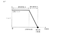
図7は実施の形態1における多重多相巻線交流モータのトルク特性を示す説明図である。同図において、トルク特性は横軸を回転数としたときのトルク値で表される。多重多相巻線交流モータの出力は回転数とトルクの積で表されるため、多重多相巻線交流モータを高出力化するためには、図7におけるトルク特性をより高トルク、高回転化する必要がある。ここで、図7に示すように、トルク特性は駆動条件の違いから運転領域Aと運転領域Bに分類できる。運転領域Aでは、モータに供給される電流量が制限されるためトルクの回転数依存性が小さく、運転領域Bでは、モータに供給される電圧量が制限されるためトルクの回転数依存性が大きい。すなわち、モータを高出力化するためには、駆動条件の異なる運転領域Aと運転領域Bのトルクを共に向上することが必要となる。 FIG. 7 is an explanatory diagram showing torque characteristics of the multiplex multiphase winding AC motor according to the first embodiment. In the figure, the torque characteristic is represented by a torque value when the horizontal axis is the rotational speed. Since the output of the multi-phase winding AC motor is represented by the product of the rotational speed and the torque, in order to increase the output of the multi-phase winding AC motor, the torque characteristics in FIG. It is necessary to make it. Here, as shown in FIG. 7, the torque characteristics can be classified into the operation region A and the operation region B based on the difference in the drive conditions. In the operation region A, the amount of current supplied to the motor is limited, and thus the dependency on the rotational speed of the torque is small. In the operation region B, the amount of voltage supplied to the motor is limited, so the dependency on the rotational speed of the torque is large. That is, in order to increase the output of the motor, it is necessary to improve both the torques in the operation region A and the operation region B having different drive conditions.
実施の形態1における多重多相巻線交流モータでは、運転領域Aではトルクを最大化するために回転数によらずほぼ一定のd軸電流を供給し、運転領域Bでは電圧飽和を緩和するために回転数毎に異なるd軸電流を供給する。ここで、実施の形態1の多重多相巻線交流モータのトルクTは以下のように表される。 In the multi-phase winding AC motor according to the first embodiment, in operation region A, a substantially constant d-axis current is supplied regardless of the rotational speed in order to maximize torque, and in operation region B, voltage saturation is alleviated. A different d-axis current is supplied for each rotation speed. Here, the torque T of the multiplex multiphase winding AC motor of the first embodiment is expressed as follows.

ただし、式(1)のφmは永久磁石によって生じる磁束量、id,iqはそれぞれ多重多相巻線に供給されるd軸,q軸電流、Pは多重多相巻線交流モータの磁極数を表す。また右辺一項目がマグネットトルクであり、二項目がリラクタンストルクを表す。実施の形態1では図8に示すように、隣り合う永久磁石19の間に、回転子鉄心(界磁極鉄心)18から突設された磁性体からなる、固定子鉄心(電機子)に対向する面の占める角度θtの突起部46を有しているため、特にq軸方向の磁束の通り易さを表すLqがLdと比較して向上する。よって、実施の形態1では運転領域Aと運転領域Bでd軸電流を供給するため式(1)のリラクタンストルクを利用することができ、前記運転領域Aと運転領域B(高速領域)のトルクを向上することができるので、多重多相巻線交流モータを高出力化できる。ここで、モータのインダクタンスLqは、図8に示すモータの突起部46が固定子鉄心に対向する面の占める角度θtに依存し、前記運転領域Aや運転領域Bのトルクは、θtを調整することで決定できる。なお、図8で、θmは回転子鉄心18の表面に設けられた永久磁石19の固定子鉄心に対向する面の占める角度であり、Oは回転子の回転中心である。
Where φm in equation (1) is the amount of magnetic flux generated by the permanent magnet, id and iq are the d-axis and q-axis currents supplied to the multiplex multiphase winding, respectively, and P is the number of magnetic poles of the multiplex multiphase winding AC motor. Represent. Also, one item on the right side is magnet torque, and two items are reluctance torque. In the first embodiment, as shown in FIG. 8, a stator core (armature) made of a magnetic material protruding from a rotor core (field magnetic core) 18 is disposed between adjacent
次に、実施の形態1における外乱電圧の影響について考える。ここで、図3より分かるように、多重化された巻線を有する多重多相巻線交流モータでは、外乱電圧が相互に作用して、電流制御系に対して外乱値iq1´、iq2´として作用する。外乱値iq1´、iq2´は、図3のq軸の等価回路のブロック図から、以下のように表される。 Next, consider the influence of the disturbance voltage in the first embodiment. Here, as can be seen from FIG. 3, in the multi-phase winding AC motor having multiplexed windings, disturbance voltages interact with each other to obtain disturbance values iq1 ′ and iq2 ′ for the current control system. Works. The disturbance values iq1 ′ and iq2 ′ are expressed as follows from the q-axis equivalent circuit block diagram of FIG.
ここで、iq1、iq2は第1巻線組,第2巻線組それぞれの巻線のq軸電流であり、Ra1、Ra2は第1巻線組,第2巻線組それぞれの巻線の抵抗値であり、Lq1,Lq2は第1巻線組、第2巻線組それぞれの巻線の自己インダクタンスのq軸成分であり、Mq12は第1巻線組,第2巻線組の巻線の干渉を表す相互インダクタンスのq軸成分である。 Here, iq1 and iq2 are q-axis currents of the respective windings of the first winding group and the second winding group, and Ra1 and Ra2 are resistances of the windings of the first winding group and the second winding group, respectively. Lq1 and Lq2 are q-axis components of the self-inductance of each of the first winding group and the second winding group, and Mq12 is the winding of the first winding group and the second winding group. It is a q-axis component of mutual inductance representing interference.
以上より、電流制御の周波数が高くなった場合、ラプラス変換の微分演算子sが大きくなり、また前記の式より、外乱値はほぼ磁気カップリングMq12/Lq1もしくは磁気カップリングMq12/Lq2に依存することは明らかである。同磁気カップリングが大きくなった場合、外乱値が大きくなり、電流制御系の外乱が大きくなると電流制御系の応答を高くすることができず、モータの制御性が悪化する。なお、実施の形態1の電機子は第1巻線組,第2巻線組が対称構造のため、Mq12/Lq1≒Mq12/Lq2と考えてもよい。よって、以後磁気カップリングはMq12/Lq1について述べる。ここで、電機子コイルU1とU2は隣り合うスロットに配置されており、隣り合うスロット間の角度をθ(電気角)としたとき、θは以下の式で表される。 From the above, when the current control frequency is increased, the Laplace transform differential operator s is increased, and the disturbance value is substantially dependent on the magnetic coupling Mq12 / Lq1 or the magnetic coupling Mq12 / Lq2 from the above equation. It is clear. When the magnetic coupling increases, the disturbance value increases. When the disturbance of the current control system increases, the response of the current control system cannot be increased, and the controllability of the motor deteriorates. The armature according to the first embodiment may be considered as Mq12 / Lq1≈Mq12 / Lq2 because the first winding group and the second winding group are symmetrical structures. Therefore, the magnetic coupling will be described for Mq12 / Lq1. Here, the armature coils U1 and U2 are arranged in adjacent slots, and θ is represented by the following expression when the angle between the adjacent slots is θ (electrical angle).
ここで、Pは多重多相巻線交流モータの磁極数、Nはスロット数であり、実施の形態1ではP=8、N=48なのでθ=30度(電気角)となる。ここで、例えば第1巻線組の電機子コイルU1に電流を供給して磁束φU1を発生させたとき、第2巻線組の電機子コイルU2に鎖交する磁束φU2は簡易的に以下のように示される。 Here, P is the number of magnetic poles of the multi-phase winding AC motor, N is the number of slots, and in the first embodiment, P = 8 and N = 48, so θ = 30 degrees (electrical angle). Here, for example, when current is supplied to the armature coil U1 of the first winding group to generate the magnetic flux φU1, the magnetic flux φU2 interlinked with the armature coil U2 of the second winding group is simply expressed as follows. As shown.
これは、電機子コイルU1とU2とが電気角でθ=30度(電気角)の位相差を有するためである。また、式(5)の関係は、他の第1巻線組,第2巻線組間の隣り合う電機子コイルの組み合わせにおいても成立する。なお、式(5)は磁束に関する関係式であるが、電機子コイルU1に電圧Vu1を印加したときに電機子コイルU2に発生する電圧Vu2についても同様の関係式が成り立つ。モータの第1巻線組のU1−V1を励磁したときに第2巻線組のU2−V2に発生する電圧についても同じ関係式が成り立つことを示している。 This is because the armature coils U1 and U2 have a phase difference of θ = 30 degrees (electrical angle) in electrical angle. Moreover, the relationship of Formula (5) is materialized also in the combination of the armature coil which adjoins between another 1st winding set and 2nd winding set. Equation (5) is a relational expression regarding magnetic flux, but the same relational expression holds for the voltage Vu2 generated in the armature coil U2 when the voltage Vu1 is applied to the armature coil U1. It shows that the same relational expression holds for the voltage generated at U2-V2 of the second winding set when U1-V1 of the first winding set of the motor is excited.
したがって、第1巻線組に電流を供給したときに前記電機子の多重多相巻線組に生じる磁束についてdq軸変換を行うと、第1巻線組のq軸磁束φq1、第2巻線組のq軸磁束φq2について以下の式が成立する。 Therefore, when dq-axis conversion is performed on the magnetic flux generated in the multi-phase winding set of the armature when current is supplied to the first winding set, the q-axis flux φq1 of the first winding set, the second winding The following formula is established for a set of q-axis magnetic flux φq2.
式(7)のように0.866では第1巻線組と第2巻線組の磁気的カップリングが大きく、電流制御系の応答を十分高くすることができず、モータの制御性が良くないという課題があった。これに対し、実施の形態1では、回転子41側の構造を工夫することで磁気的カップリングを低減している。図5に示すように回転子41は回転子鉄心18の表面に永久磁石19を配置している。永久磁石19は周方向に8個配置されていて、それぞれの着磁方向は周方向に隣り合う永久磁石19の着磁方向が互いに逆になるように着磁されている。回転子鉄心18の表面に永久磁石19を配置することで回転子41と固定子42の間の磁気的ギャップを大きくできるため第1巻線組と第2巻線組の磁気的カップリングを低減できるという効果が得られる。
As shown in equation (7), at 0.866, the magnetic coupling between the first winding group and the second winding group is large, and the response of the current control system cannot be sufficiently increased, and the controllability of the motor is good. There was no problem. On the other hand, in the first embodiment, the magnetic coupling is reduced by devising the structure on the
また、隣り合う永久磁石19の間には突起部46が設けられている。この突起部46は磁性体で構成されている。回転子鉄心18は電磁鋼板やSPCC(冷間圧延鋼板)などの鋼板を積層して構成されていて、突起部46はこの電磁鋼板やSPCCを金型で打ち抜くことで一体となるように構成される。突起部46があるために、インダクタンスを向上し、弱め磁束制御の効果を発揮しやすく、高速回転でのトルクを向上できるという効果がある。また、リラクタンストルクを発生させることができ、モータのトルクが向上でき永久磁石19の使用量を低減することができるという効果がある。永久磁石19と突起部46の間には、突起部46の両側に非磁性のギャップ部47を設けている。ギャップ部47は空隙(空気)であってもよいし、アルミニウムやSUS(ステンレス鋼)などの非磁性の金属あるいは樹脂などで構成されていてもよい。ギャップ部47が空隙の場合は重量が軽減できる。
In addition, a
非磁性のギャップ部47があることで、永久磁石19と突起部46の間に発生する漏れ磁束を低減することができる。したがって、トルクが向上し永久磁石19の使用量を低減することができるという効果がある。また、同時にこの非磁性のギャップ部47は固定子42と回転子41の磁気的ギャップとしても作用するため、第1巻線組と第2巻線組の巻線間の磁気的カップリングを低減できるという効果がある。
The presence of the
図15は実施の形態1における回転子を示す斜視図である。図15では永久磁石19と突起部46の間に設けられた非磁性のギャップ部47は軸方向全域にわたって設けられている。このような構成とすることで、永久磁石19と突起部46の間に発生する漏れ磁束を効果的に低減できるとともに前述した磁気的カップリングも効果的に低減できるという効果が得られる。ただし、非磁性のギャップ部47は軸方向全域にわたって設ける必要は必ずしもない。軸方向の一部の領域で突起部46の幅を大きくして、永久磁石19の側面と当接する構成とすれば、永久磁石19の周方向の位置決めが可能となるため、永久磁石19を配置する位置精度が向上できる。その結果、回転子側のアンバランスに起因するトルクリップルを低減できるという効果がある。
FIG. 15 is a perspective view showing the rotor in the first embodiment. In FIG. 15, the
以上のような構成とすることで、
とすることができ、制御性を向上できるという効果も得られる。これによって、モータの第1巻線組のU1−V1端子を電圧Vu1-v1で励磁したときに第2巻線組のU2−V2端子に発生する電圧Vu2-v2について The controllability can be improved. As a result, the voltage Vu2-v2 generated at the U2-V2 terminal of the second winding set when the U1-V1 terminal of the first winding set of the motor is excited with the voltage Vu1-v1.
が成り立つことを示している。交流電圧を第1巻線組のモータ端子に印加し、第2巻線組のモータ端子の電圧を測定したときの電圧波形を図17に示す。縦軸の電圧はVu1-v1が1となるように規格化している。また、電圧の周波数は電機子巻線のリアクタンスに対して抵抗が無視できるほど周波数の高い周波数として1kHzとした。また、電圧波形は正弦波とした。図17から、Vu2-v2はVu1-v1に0.866を乗じた値より十分小さくなっているため、式(9)の条件をみたし、第1巻線組と第2巻線組の間の磁気的カップリングが小さく制御性のよいモータが得られたことがわかる。 It is shown that holds. FIG. 17 shows a voltage waveform when an AC voltage is applied to the motor terminal of the first winding group and the voltage of the motor terminal of the second winding group is measured. The voltage on the vertical axis is normalized so that Vu1-v1 is 1. Further, the frequency of the voltage was set to 1 kHz as a high frequency so that the resistance with respect to the reactance of the armature winding can be ignored. The voltage waveform was a sine wave. From FIG. 17, Vu2-v2 is sufficiently smaller than the value obtained by multiplying Vu1-v1 by 0.866. Therefore, the condition of equation (9) is satisfied, and the relationship between the first winding set and the second winding set is satisfied. It can be seen that a motor with small magnetic coupling and good controllability was obtained.
さらに、非磁性のギャップ部47を設けたことで前述したように永久磁石19と突起部46の漏れ磁束の低減と高速回転時のトルク向上といった効果も得られる。なお、前記の説明においては、巻線組が電気的に30°の位相差を有している8極48スロットの多重多相巻線交流モータで説明を行ったが、この巻線組間の位相差、極数、スロット数に限定されるものではなく、巻線が電気的に2つに分離されており、またそれぞれの巻線組が異なるモータ駆動装置で駆動されている多重多相巻線交流モータについて、前記と同様の効果が得られる。
Furthermore, by providing the
また、前記の説明において、電機子巻線は複数個のティース44に跨って巻回されている場合について説明したが、1つのティース44に集中的に巻回されている場合においても前記と同様の論理が成立する。また、前記の説明においては電機子巻線の巻線ピッチを電気角180°の全節巻とした場合について説明したが、電気角180°以外とした場合でも前記と同様の効果が得られる。また、前記の説明においては、巻線が電気的に2つの巻線組に分離されており、かつ2つの異なるモータ駆動装置で駆動されている多重多相巻線交流モータについて説明を行ったが、巻線組の分離される数やモータ駆動装置の数が増加した場合についても前記と同様の効果が得られる。
In the above description, the case where the armature winding is wound across a plurality of
実施の形態1の多重多相巻線交流モータを電動パワーステアリング装置に適用すれば、トルクリップルを低減して、ドライバーの操舵フィーリングを向上できる。また、電動パワーステアリング装置が搭載された車両の静粛性を向上することができる。多重多相巻線交流モータの出力が向上するので、電動パワーステアリング装置を小型化、軽量化でき、電動パワーステアリング装置が搭載された車両を小型化、軽量化できるという効果が得られる。 If the multiple multiphase winding AC motor of the first embodiment is applied to the electric power steering apparatus, torque ripple can be reduced and the steering feeling of the driver can be improved. Further, it is possible to improve the quietness of a vehicle equipped with the electric power steering device. Since the output of the multi-phase winding AC motor is improved, the electric power steering device can be reduced in size and weight, and the vehicle equipped with the electric power steering device can be reduced in size and weight.
実施の形態2.
図8は回転子の構造を示し、簡略化のため2極分のみを示す。突起部46において固定子鉄心に対向する面の占める角度をθtとする。図9は図8においてθtを変化させたときの無負荷回転数、鉄心長(鉄心の回転軸方向の長さ)を示す図である。値は突起部46を設けない場合、すなわちθt=0のときの値に対する比率である。θtは電気角で表している。永久磁石19はモータ断面(回転軸に垂直は断面)での断面積が一定となる条件を課しており、定格トルクがθt=0の場合と等しくなるように鉄心長を調整している。突起部46の幅θtを0から大きくしていくと、突起部46の幅が増していくので、マグネットトルクに代わってリラクタンストルクを利用できるようになるので、鉄心長が減少し、巻線抵抗も減少し、無負荷回転数が大きくなる。0<θt≦50(度)とするとモータ鉄心長を小さくできると同時に無負荷回転数が大きくなる。運転領域B(高速領域)ではリラクタンストルク、運転領域A(低回転領域)はマグネットトルクを利用でき、回転軸長を突起部を設けない場合と比較して増加させずに運転領域Bのトルクを向上できる。
FIG. 8 shows the structure of the rotor, and only two poles are shown for simplicity. The angle occupied by the surface of the
また、前述したように回転子鉄心の表面に永久磁石19を配置することで回転子41と固定子42の間の磁気的ギャップを大きくできるため、第1巻線組と第2巻線組の磁気的カップリングを低減できるという効果が得られる。また、永久磁石19と突起部46の間には非磁性のギャップ部47を設けているので永久磁石19と突起部46の間に発生する漏れ磁束を低減でき、同時にこの非磁性のギャップ部47は固定子42と回転子41の磁気的ギャップとしても作用するため、第1巻線組と第2巻線組の電機子コイル間の磁気的カップリングを低減できるという効果がある。
Moreover, since the magnetic gap between the
特に電動パワーステアリング用モータでは、緊急回避時に障害物を回避するためにハンドルを高速で切らなければいけないので高速回転数が必要であると共に、車庫入れや駐車時には高トルクが必要である。さらに、燃費が悪化する重量増加は避けなればならないこと、取付け性を悪化させないために長さを長くできないこと、などから突起部46のないθt=0と同等の鉄心長を制約に加えると、0<θt≦50(度)が最適な範囲であるといえる。
In particular, an electric power steering motor requires a high rotational speed because it must be turned at a high speed in order to avoid obstacles during emergency avoidance, and requires a high torque during garage entry and parking. Furthermore, if an increase in weight that deteriorates fuel consumption must be avoided, the length cannot be increased because the attachment performance is not deteriorated, and the iron core length equivalent to θt = 0 without the
実施の形態3.
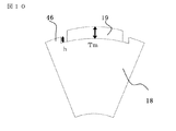
図10は回転子の構造を示し、簡略化のため1極分のみを示す。永久磁石19の厚さをTm、突起部46の高さ(突起部46の永久磁石の下端面からの高さ)をhとする。図11は永久磁石19の厚さTmを一定として突起部46の高さhを変えたときの無負荷回転数、鉄心長を示す図である。値は突起部46がない場合h=0に対する比率である。永久磁石19はモータ断面での断面積が一定となる条件を課しており、定格トルクがh=0の場合と等しくなるように鉄心長を調整している。
FIG. 10 shows the structure of the rotor, and only one pole is shown for simplicity. The thickness of the
h/Tmが大きくなるにつれて突起部46の高さが増していくので、マグネットトルクに代わってリラクタンストルクを利用できるようになり、鉄心長が減少し、巻線抵抗も減少し、無負荷回転数が大きくなる。h/Tm=1、つまり、突起部46の高さが永久磁石19厚さと等しいときに、鉄心長は最小となる。一般にリラクタンスモータのように突極性の大きなモータはトルクリップルが大きくなるので、h/Tm>1の範囲は操舵フィーリングが悪化するので望ましくなく、0<h/Tm≦1の範囲が、モータ制御性と高回転性能を満たす最適な範囲である。この領域でも突起部46がない場合に比べて、鉄心長が短くできることから、モータが小型化できるため、燃費向上や取付け性の面で優位である。
Since the height of the
また、前述したように回転子鉄心18の表面に永久磁石19を配置することで回転子41と固定子42の間の磁気的ギャップを大きくできるため、第1巻線組と第2巻線組の磁気的カップリングを低減できるという効果が得られる。また、永久磁石19と突起部46の間には非磁性のギャップ部47を設けているので永久磁石19と突起部46の間に発生する漏れ磁束を低減でき、同時にこの非磁性のギャップ部47は固定子42と回転子41の磁気的ギャップとしても作用するため、第1巻線組と第2巻線組の電機子コイル間の磁気的カップリングを低減できるという効果がある。
Further, since the
実施の形態4.
図12は回転子の構造を示し、簡略化のため1極分のみを示す。永久磁石19と突起部46の間の非磁性のギャップ部分47の周方向の角度をθa1,θa2とする。ここではθa1=θa2としている。θa1=θa2とすることで、磁気的なバランスが取れるためトルクリップルが小さくできるという効果がある。図13は突起部46の幅を一定としたまま、永久磁石19と突起部46の間隔すなわち非磁性のギャップ部47の周方向の角度を変化させた場合の定格トルクの変化を示す図である。値は間隔がゼロの時を100%とした場合の比率である。横軸のθaはθa=θa1+θa2として定義している。
Embodiment 4 FIG.
FIG. 12 shows the structure of the rotor, and only one pole is shown for simplicity. The angles in the circumferential direction of the
間隔θaが0から大きくなるにつれて、永久磁石19の磁束が回転子41内で漏れる量が減少するため、トルクに寄与する磁束量が増加し、定格トルクが増加していく。間隔θaが10度を越えるとトルクに寄与する永久磁石19磁束が減少していくので、永久磁石19磁束そのものの減少する影響が大きくなっていく。間隔θaが20度を超えると、間隔0の場合よりも定格トルクは減少してしまう。
As the interval θa increases from 0, the amount of magnetic flux leaking from the
以上より、0<θa<20°の範囲が定格トルクを大きくする最適な範囲である。また、前述したように回転子鉄心18の表面に永久磁石19を配置することで回転子41と固定子42の間の磁気的ギャップを大きくできるため第1巻線組と第2巻線組の磁気的カップリングを低減できるという効果が得られる。また、永久磁石19と突起部46の間には非磁性のギャップ部47を設けているので、永久磁石19と突起部46の間に発生する漏れ磁束を低減でき、同時にこの非磁性のギャップ部47は固定子42と回転子41の磁気的ギャップとしても作用するため、第1巻線組と第2巻線組の電機子コイル間の磁気的カップリングを低減できるという効果がある。
From the above, the range of 0 <θa <20 ° is the optimum range for increasing the rated torque. Further, as described above, by arranging the
実施の形態5.
これまでの実施の形態1〜4では非磁性のギャップ部47がモータの回転軸方向に均一に設けられた例について述べたが、これに限らない。図14は実施の形態5における突起部46のある鉄心と、突起部46のない、もしくは突起部46の小さな鉄心、又は永久磁石押さえとなる突起部46を有する鉄心を組み合わせて積層した構成を示す説明図である。簡略化のため1極分のみ示している。
In the first to fourth embodiments so far, the example in which the
図14においてA1,A2で示した部分は突起部46が永久磁石19と当接していて非磁性のギャップ部47がない領域である。B1,B2で示した部分は非磁性のギャップ部47を設けた領域である。C1,C2で示した部分はB1,B2よりも広い非磁性のギャップ部47を設けた領域である。Dは突起部46のない領域である。A1,A2で示した領域の突起部46は永久磁石19の位置決めに利用できる。また、突起部46の幅や高さなど形状が異なるとトルクリップルやコギングトルクを変化させることができるため、図14のように、これらを回転軸方向に組み合わせることでトルクリップルやコギングトルクを低減できるという効果が得られる。また図14のような、回転子鉄心18は金型の構成を工夫することで積層可能であり、大幅にコストアップすることなく上記効果を得ることができる。
In FIG. 14, the portions indicated by A <b> 1 and A <b> 2 are regions where the
実施の形態6.
これまでの実施の形態1〜5では、永久磁石19と回転子鉄心18の突起部46の間の非磁性のギャップ部は空気である例について述べてきた。しかし、本発明はそれに限らない。図16は非磁性のギャップ部を樹脂部材48で構成した回転子を示す斜視図である。非磁性のギャップ部は樹脂部材が永久磁石19の側面に当接するように配置されている。これにより、永久磁石19の周方向の位置決めが可能となり、回転子側の製造ばらつきを低減できるため、コギングトルクやトルクリップルの小さいモータを得ることができるという効果がある。また、樹脂部材48によって永久磁石19の径方向を固定することで、永久磁石19の飛散防止の効果が得られる。また、接着剤を省略すれば、生産コストや材料コストを低減できるという効果が得られる。非磁性部のギャップ部47は樹脂に限らず、非磁性のアルミニウム,SUSなどの金属でも同じ効果が得られる。ただし、樹脂は金属と比べて軽量であるため、モータの軽量化やイナーシャ低減の効果がある。
なお、本発明は、その発明の範囲内において、各実施の形態を自由に組み合わせたり、各実施の形態を適宜、変形、省略することが可能である。
In the first to fifth embodiments so far, the example in which the non-magnetic gap between the
It should be noted that the present invention can be freely combined with each other within the scope of the invention, and each embodiment can be appropriately modified or omitted.
Claims (3)
前記電機子巻線は複数組の多相巻線であり、
前記電機子巻線の複数組はそれぞれ個別のインバータから電流が供給され、
前記回転子鉄心の表面部には、永久磁石が周方向に配置され、隣り合う前記永久磁石の極性が互いに逆であり、
隣り合う前記永久磁石の間には、前記回転子鉄心から突設された磁性体からなる突起部が設けられ、
前記突起部と前記永久磁石との間には回転軸方向の全部又は一部に非磁性のギャップ部が介在し、隣り合う前記永久磁石の間に前記回転子鉄心から突設された前記突起部は、前記回転子鉄心の周方向に占める角度が異なる前記突起部を有する鋼板が組み合わさって積層して構成され、且つ前記突起部の一部は隣り合う前記永久磁石に当接して配置されていることを特徴とする永久磁石型モータ。 A stator having a stator core in which an armature winding is housed in a slot, and a rotor core facing the stator via an air gap on the inner peripheral side of the stator, and can be rotated around a rotating shaft. And a rotor supported by
The armature winding is a plurality of sets of multiphase windings,
The plurality of sets of armature windings are each supplied with current from an individual inverter,
On the surface portion of the rotor core, permanent magnets are arranged in the circumferential direction, and the polarities of the adjacent permanent magnets are opposite to each other,
Between the adjacent permanent magnets, there is provided a protrusion made of a magnetic material protruding from the rotor core,
A non-magnetic gap is interposed between the protrusion and the permanent magnet in the whole or a part in the rotation axis direction, and the protrusion protrudes from the rotor core between the adjacent permanent magnets. Is formed by combining and stacking steel plates having the protrusions having different angles in the circumferential direction of the rotor core, and a part of the protrusions are disposed in contact with the adjacent permanent magnets. A permanent magnet type motor characterized by having
前記電機子巻線の第1組は第1インバータから電流が供給され、
前記電機子巻線の第2組は第2インバータから電流が供給され、
前記2組の3相巻線について、前記電機子巻線の第1組をU1相,V1相,W1相とし、前記電機子巻線の第2組をU2相,V2相,W2相としたとき、
前記U1相とU2相の巻線は互いに隣り合うスロットに納められ、
前記V1相とV2相の巻線は互いに隣り合うスロットに納められ、
前記W1相とW2相の巻線は互いに隣り合うスロットに納められ、
前記第1組の3相巻線と前記第2組の3相巻線とに流れる電流の位相を互いに電気角20度以上40度以下の角度ずらして、前記第1インバータと第2インバータが駆動されることを特徴とする請求項1記載の永久磁石型モータ。 The armature windings are two sets of three-phase windings,
The first set of armature windings is supplied with current from a first inverter,
The second set of armature windings is supplied with current from a second inverter,
For the two sets of three-phase windings, the first set of armature windings are U1, V1, and W1, and the second set of armature windings are U2, V2, and W2 phases. When
The U1 phase and U2 phase windings are placed in adjacent slots,
The V1 phase and V2 phase windings are placed in adjacent slots,
The W1 phase and W2 phase windings are placed in adjacent slots,
The first inverter and the second inverter are driven by shifting the phases of the currents flowing through the first set of three-phase windings and the second set of three-phase windings from an electrical angle of 20 degrees to 40 degrees. The permanent magnet motor according to claim 1, wherein
Priority Applications (1)
| Application Number | Priority Date | Filing Date | Title |
|---|---|---|---|
| JP2016181364A JP6282326B2 (en) | 2016-09-16 | 2016-09-16 | Permanent magnet type motor and electric power steering device |
Applications Claiming Priority (1)
| Application Number | Priority Date | Filing Date | Title |
|---|---|---|---|
| JP2016181364A JP6282326B2 (en) | 2016-09-16 | 2016-09-16 | Permanent magnet type motor and electric power steering device |
Related Parent Applications (1)
| Application Number | Title | Priority Date | Filing Date |
|---|---|---|---|
| JP2015510991A Division JP6305394B2 (en) | 2013-04-09 | 2013-04-09 | Permanent magnet type motor and electric power steering device |
Publications (2)
| Publication Number | Publication Date |
|---|---|
| JP2016214081A JP2016214081A (en) | 2016-12-15 |
| JP6282326B2 true JP6282326B2 (en) | 2018-02-21 |
Family
ID=57552108
Family Applications (1)
| Application Number | Title | Priority Date | Filing Date |
|---|---|---|---|
| JP2016181364A Active JP6282326B2 (en) | 2016-09-16 | 2016-09-16 | Permanent magnet type motor and electric power steering device |
Country Status (1)
| Country | Link |
|---|---|
| JP (1) | JP6282326B2 (en) |
Families Citing this family (6)
| Publication number | Priority date | Publication date | Assignee | Title |
|---|---|---|---|---|
| US11289960B2 (en) | 2017-07-20 | 2022-03-29 | Mitsuba Corporation | Motor and brushless wiper motor |
| CN108319768B (en) * | 2018-01-23 | 2021-08-31 | 湖北西浦电机科技有限责任公司 | Permanent magnet motor armature reaction magnetic field prediction method based on computer |
| JP6897614B2 (en) * | 2018-03-27 | 2021-06-30 | 株式会社デンソー | motor |
| DE112019001628T5 (en) * | 2018-03-27 | 2020-12-10 | Denso Corporation | ENGINE |
| JP2020080609A (en) | 2018-11-13 | 2020-05-28 | 株式会社ミツバ | Motor and brushless wiper motor |
| CN111799911A (en) * | 2020-06-28 | 2020-10-20 | 东南大学 | Modularized separated winding motor |
Family Cites Families (3)
| Publication number | Priority date | Publication date | Assignee | Title |
|---|---|---|---|---|
| US6597078B2 (en) * | 2000-12-04 | 2003-07-22 | Emerson Electric Co. | Electric power steering system including a permanent magnet motor |
| JP5228582B2 (en) * | 2008-04-04 | 2013-07-03 | 三菱電機株式会社 | Permanent magnet type rotating electric machine and electric power steering device using the same |
| JP5760830B2 (en) * | 2011-08-09 | 2015-08-12 | 株式会社デンソー | Control device for three-phase rotating machine |
-
2016
- 2016-09-16 JP JP2016181364A patent/JP6282326B2/en active Active
Also Published As
| Publication number | Publication date |
|---|---|
| JP2016214081A (en) | 2016-12-15 |
Similar Documents
| Publication | Publication Date | Title |
|---|---|---|
| JP6305394B2 (en) | Permanent magnet type motor and electric power steering device | |
| JP6282326B2 (en) | Permanent magnet type motor and electric power steering device | |
| JP6091619B2 (en) | Permanent magnet type motor and electric power steering device | |
| JP6124999B2 (en) | Permanent magnet type motor for electric power steering | |
| US7714466B2 (en) | Claw-teeth-type rotating electrical machine | |
| JP5605388B2 (en) | Synchronous motor | |
| JP5932147B2 (en) | Multiple multi-phase winding AC rotating electric machine and electric power steering device | |
| EP2966755B1 (en) | Multi-winding multi-phase ac motor and electric power-steering device | |
| JP6157652B2 (en) | Permanent magnet type motor | |
| US20080218023A1 (en) | Brushless motor and electric power steering device having brushless motor | |
| JP6234558B2 (en) | Permanent magnet type motor | |
| JP6188639B2 (en) | Electric motor | |
| KR20150038854A (en) | Motor for implementing 2-mode neutral point winding and Electric vehicle using the same |
Legal Events
| Date | Code | Title | Description |
|---|---|---|---|
| A621 | Written request for application examination |
Free format text: JAPANESE INTERMEDIATE CODE: A621 Effective date: 20160916 |
|
| A131 | Notification of reasons for refusal |
Free format text: JAPANESE INTERMEDIATE CODE: A131 Effective date: 20170411 |
|
| A977 | Report on retrieval |
Free format text: JAPANESE INTERMEDIATE CODE: A971007 Effective date: 20170412 |
|
| A02 | Decision of refusal |
Free format text: JAPANESE INTERMEDIATE CODE: A02 Effective date: 20170926 |
|
| A521 | Written amendment |
Free format text: JAPANESE INTERMEDIATE CODE: A523 Effective date: 20171026 |
|
| A911 | Transfer to examiner for re-examination before appeal (zenchi) |
Free format text: JAPANESE INTERMEDIATE CODE: A911 Effective date: 20171108 |
|
| TRDD | Decision of grant or rejection written | ||
| A01 | Written decision to grant a patent or to grant a registration (utility model) |
Free format text: JAPANESE INTERMEDIATE CODE: A01 Effective date: 20180116 |
|
| A61 | First payment of annual fees (during grant procedure) |
Free format text: JAPANESE INTERMEDIATE CODE: A61 Effective date: 20180123 |
|
| R151 | Written notification of patent or utility model registration |
Ref document number: 6282326 Country of ref document: JP Free format text: JAPANESE INTERMEDIATE CODE: R151 |
|
| R250 | Receipt of annual fees |
Free format text: JAPANESE INTERMEDIATE CODE: R250 |
|
| R250 | Receipt of annual fees |
Free format text: JAPANESE INTERMEDIATE CODE: R250 |
|
| R250 | Receipt of annual fees |
Free format text: JAPANESE INTERMEDIATE CODE: R250 |