JP6281803B2 - Drainage equipment - Google Patents
Drainage equipment Download PDFInfo
- Publication number
- JP6281803B2 JP6281803B2 JP2013024319A JP2013024319A JP6281803B2 JP 6281803 B2 JP6281803 B2 JP 6281803B2 JP 2013024319 A JP2013024319 A JP 2013024319A JP 2013024319 A JP2013024319 A JP 2013024319A JP 6281803 B2 JP6281803 B2 JP 6281803B2
- Authority
- JP
- Japan
- Prior art keywords
- drainage
- container
- water
- peripheral side
- side plate
- Prior art date
- Legal status (The legal status is an assumption and is not a legal conclusion. Google has not performed a legal analysis and makes no representation as to the accuracy of the status listed.)
- Active
Links
Images


Description
本発明は、屋内外の様々な場所に雨水その他の水が滞留した場合、特に建築途上の建築物のベタ基礎の上等に雨水等が滞留したような場合に、そのような滞留水を容易かつ確実に排水し、かつその滞留領域を乾燥状態にまですることができる排水装置に関する。 The present invention facilitates the retention of rainwater and other water in various places indoors and outdoors, especially when rainwater or the like stays on a solid foundation of a building under construction. In addition, the present invention relates to a drainage device capable of draining reliably and making the staying region dry.
ポンプ装置は種々のそれが市販されているが、それらは、池、川、湖、井戸又はタンク等からくみ出すのに適当なものであり、それらの中には、浅く広く滞留している水をその外側の適当な場所に排出するのに適切なそれは見出し得ない。更に排水後にその領域を乾燥させることまでできる装置は全く見出し得ない。また若干の調査をしてみたが、前記の用途の排水装置として適切な装置は特許等の提案もされていないように思われる。 There are a variety of pump devices available on the market, which are suitable for pumping out of ponds, rivers, lakes, wells or tanks, etc. It is not possible to find it appropriate to discharge the water to a suitable place outside it. Furthermore, no device can be found that can dry the area after draining. In addition, after some investigations, it seems that no device has been proposed for a device suitable as a drainage device for the above-mentioned use.
特許文献1は、雨水排水ポンプ装置に関するものであり、排水ポンプの上流側に十分な大きさの沈砂池を設けることが困難な雨水排水ポンプ装置において、前記排水ポンプの上流側に設置された着水井の底面部に段差を設けたものである。
この特許文献1によれば、雨水を着水井に導入して流速を低下させ、その底部に構成した段差部の直前に該雨水中の土砂を堆積させることにより、下流側に配した排水ポンプの吸込口側の吸水槽への土砂の堆積を防止することができると云うものである。そのように作用することは確かであると思われるが、排水ポンプそれ自体は既存のそれであると思われ、例えば、建築途上の建築物の基礎上面上に滞留した雨水の排水のような深度の浅い滞留水の排水は困難であると思われ、更に排水後に引き続いてその領域の乾燥を行うことはは全く不可能である。
According to this
特許文献2は、排水ポンプに関するものであり、羽根車入口側の吸込ケーシングに貫通孔を形成し、外部に連通する空気管を前記貫通孔に接続した排水ポンプにおいて、羽根車の下流側に水抜き用の配管及びそれに介装された開閉弁を設け、該配管は羽根車上流側に連通しており、排水を停止した際に羽根車下流側の圧力を低減するべく開閉弁を開放するように制御する制御機構を備えているものである。
この特許文献2の排水ポンプによれば、前回の排水時に水槽の水位が低下し羽根車入口近傍に空気が入り、これが、次に水位が上がって排水運転を開始するときに、その部位に残留していた場合には、その空気を排出することが可能であり、かつ羽根車下流側の圧力を低減すべく開閉弁が開放されることになる。それ故、待機状態から排水運転を開始した際に、揚水又は排水を確実に行うことができるとされている。そしてこのように作用することは確かなことであると思われるが、この特許文献2の排水ポンプは、ポンプ装置自体は、渦巻ポンプ又は車流ポンプ等の従来のポンプ装置であり、例えば、前記した建築途上の建築物の基礎上面上に滞留した雨水の排水のような、深度の浅い滞留水の排水は困難であると思われ、更に排水後に引き続いてその領域の乾燥を行うことは全く不可能である。
According to the drainage pump of
特許文献3は、排水ポンプに関するものであり、原動機の回転出力が減速機もしくは可変速流体継手を組込んだ複合減速機を介して主軸に伝達されるように構成されている排水ポンプにおいて、前記原動機の出力回転軸から排水ポンプの主軸に至る動力伝達系に2個の可変速流体継手を直列状に介設したものである。
この特許文献3の排水ポンプによれば、通常排水時には、原動機の定格運転により排水ポンプを高速回転駆動する大量排水運転を行って、大量の雨水の排水に対応し、少降雨時および極少降雨時には、原動機の低出力回転と2個の可変速流体継手の変速操作との協働によって、排水ポンプを極低速回転運動させて、極少量排水運転を行うことにより、河川から吸水井に流入して来た極小量の雨水の排水に適切に対応することができる。それ故、少降雨時および極少降雨時において排水ポンプにより排水運転が開始されても、吸水井の水位の急激な昇降が繰り返されるようなことはなくなる。また水位が運転可能水位未満まで低下するようなこともなくなり、排水ポンプの空気の吸い込みを回避することができる。その結果、大きな振動や騒音が発生しなくなるものでもある。この特許文献3の排水ポンプによれば、このような作用及び効果が得られることは認められる。
According to the drainage pump disclosed in
しかしこの特許文献3の排水ポンプもポンプ本体は、既存のそれであり、特許文献1、2の雨水排水ポンプ装置又は排水ポンプと同様に、建築途上の建築物の基礎上面上に滞留した雨水の排水のような深度の浅い滞留水の排水は困難であると思われ、更に排水後のその領域の乾燥を行うことはやはり全く不可能である。
However, the drainage pump of
本発明は、屋内外の様々な場所に雨水その他の水が滞留した場合に、そのような滞留水の全てを容易かつ確実に排水すると共に、必要に応じてその滞留領域を乾燥状態にまですることも可能な排水装置を提供することを解決の課題とする。 In the case where rainwater or other water stays in various places indoors or outdoors, the present invention drains all such staying water easily and reliably, and makes the staying area dry if necessary. An object of the present invention is to provide a drainage device that can also be used.
本発明の1は、上面を天板部で、周囲を下方に垂下する周側板で、それぞれ閉じた下部開口の容器状装置本体と、圧縮空気を導入し、その圧縮空気を前記容器状装置本体の内部空間から排水口に噴出させるノズル部と、前記容器状装置本体の先端側の天板部又は周側板に開口した排水口であって、排水動作時に前記ノズル部から噴出する空気噴流により前記周側板の下端と排水対象部位の底面との間から吸引される排水対象水を該空気噴流と共に排水する排水口と、該排水口から該排水対象水及び該空気噴流を外部に案内排水する、外端が排水端である排水案内管であって、該排水口から斜め上向きに延びる剛性かつ直線状の管体で構成した排水案内管と、で構成した排水装置である。A first aspect of the present invention is a container-like device main body having a closed lower opening and a compressed air introduced into the container-like device main body, each of which is closed by a top plate portion and a peripheral side plate that hangs downward around the periphery. A nozzle part to be ejected from the internal space to the drain port, and a drain port opened to a top plate part or a peripheral side plate on the front end side of the container-like device body, and the air jet spouted from the nozzle part during a draining operation A drainage outlet for draining the drainage target water sucked from between the lower end of the peripheral side plate and the bottom surface of the drainage target part together with the air jet, and the drainage target water and the air jet are guided and drained from the drainage outlet to the outside . A drainage guide pipe having an outer end that is a drainage end and a drainage guide pipe that is configured by a rigid and linear pipe body that extends obliquely upward from the drainage port .
本発明の2は、本発明の1の排水装置において、
前記容器状装置本体の周側板の下端に、排水動作時に、排水対象部位の底面との間に微小隙間をあけるための複数の隙間形成用の微小突起を突出させたものである。
2 of the present invention is the drainage device of 1 of the present invention,
In the lower end of the peripheral side plate of the container-like device main body, a plurality of microprojections for forming a gap for projecting a microgap between the bottom surface of the site to be drained is projected during the drainage operation.
本発明の1の排水装置は、そのノズル部にホース部材等を介してコンプレッサを接続し、排水対象水の滞留している排水対象部位にセットして使用する。前記容器状装置本体の下部開口を下に向け、かつ前記排水案内管の外端の吐出口を排水の受け入れ可能な場所に向けた状態にして該排水対象部位にセットする。排水対象水は特に限定されない。種々の無用の滞留水等である。例えば、建築途上の建築物等のベタ基礎上に滞留した雨水等であり、そのような滞留雨水等の排水対象水の滞留する排水対象部位に、前記のように、この装置の容器状装置本体を下部開口を下向きにして沈め、前記コンプレッサを動作させると、該コンプレッサで発生された圧縮空気が前記ホース部材等を介してこの装置に圧送され、前記ノズル部に導入され、該ノズル部を通じて前記内部空間から排水口に噴出されることになる。 The drainage apparatus of 1 of this invention connects a compressor to the nozzle part via a hose member etc., and uses it by setting to the waste_water | drain target site | part where the drainage target water is stagnating. The container-like device main body is set in the drainage target portion with the lower opening facing downward and the discharge port at the outer end of the drainage guide tube facing the place where drainage can be received. The target water for drainage is not particularly limited. These are various kinds of unwanted water. For example, it is rain water etc. which stayed on a solid foundation such as a building under construction, and the container-like device main body of this device as described above is disposed in the drainage target portion where the drainage target water such as the staying rainwater stays. When the compressor is operated by lowering the lower opening downward, the compressed air generated by the compressor is pumped to the device through the hose member and the like, introduced into the nozzle portion, and through the nozzle portion. It will be ejected from the internal space to the drain.
空気噴流が、前記のように、ノズル部を通じて前記排水口側に流れると、これによって前記容器状装置本体の周側板の下端と排水対象部位の底面との間の微小隙間を通じて滞留雨水等の排水対象水が吸引導入され、該噴流空気と共に前記排水口側に導かれることになる。滞留雨水等の排水対象水が該容器状装置本体の周囲に存在している限り、その吸引及び排水口側への導き作用が継続し、いずれその周囲の排水対象水は全て排水されることになる。 When the air jet flows to the drain outlet side through the nozzle portion as described above, the drainage of the accumulated rainwater or the like through the minute gap between the lower end of the peripheral side plate of the container-like device body and the bottom surface of the drainage target portion. The target water is sucked and introduced together with the jet air to the drain port side. As long as target water such as accumulated rainwater exists around the main body of the container-like device, the suction and the guiding action to the drain outlet side will continue, and all the target drainage water will eventually be drained. Become.
前記容器状装置本体を排水対象水が滞留した排水対象部位に配置すると、前記周側板の下端と該排水対象部位の底面との間には微小隙間があくことになる。すなわち、排水対象水が滞留する排水対象部位の底面が完全に平坦であることは殆どあり得ないので、前記容器状装置本体の周側板の下端が、たとえ、直線的な構成であっても、殆どの場合に、該周側板の下端と該排水対象部位の底面とは、いくつかの部位で接触しつつ、その間には微小隙間があくことになる。 When the container-like device body is disposed in the drainage target site where the drainage target water stays, there is a minute gap between the lower end of the peripheral side plate and the bottom surface of the drainage target site. That is, since it is almost impossible that the bottom surface of the drainage target portion where the drainage target water stays is completely flat, even if the lower end of the peripheral side plate of the container-like device body has a linear configuration, In most cases, the lower end of the peripheral side plate and the bottom surface of the drainage target part are in contact with each other at some parts, and there are minute gaps therebetween.
以上のようにして該容器状装置本体の周側板の下端と排水対象部位の底面との間の殆どの部分に微小隙間が生じることにより、該微小隙間を通じて周囲の深度の非常に浅い滞留水、たとえば、1mm以下の深度若しくは底面を濡らしている程度の滞留水をも引き込むことが可能になる。深度の浅い滞留水は霧状になって引き込まれることになる。このように濡れている程度までの滞留水が吸引排出できることにより、滞留水を単に排水するのみではなく、乾燥させるところまで進めることも可能になる。なお、以上のような深度の浅い滞留水ばかりでなく、深度の深い滞留水が吸引できることは言うまでも無い。 As described above, a minute gap is generated in almost the portion between the lower end of the peripheral side plate of the container-like device main body and the bottom surface of the drainage target part, so that the stagnant water having a very shallow surrounding depth through the minute gap, For example, it becomes possible to draw in the stagnant water having a depth of 1 mm or less or wetness of the bottom surface. The shallow water will be drawn in the form of mist. Since the accumulated water up to the wet level can be sucked and discharged in this way, it is possible not only to drain the accumulated water but also to proceed to the place of drying. In addition, it cannot be overemphasized that not only the shallow stagnant water as mentioned above but the deep stagnant water can be sucked.
該容器状装置本体の内部空間に引き込まれた滞留水は該内部空間を通過して更に前記排水口に引き込まれ、前記排水案内管の内部を通じて外部に移動し、その吐出口から排水の受け入れ可能な場所に吐出されることになる。該排水案内管は、ノズル部から噴出される空気噴流に引き込まれる滞留水を、その拡大拡散を抑えつつ吐出口まで案内する管体であり、そのように作用する。その長さは、ノズル部から噴出される圧縮空気の量及び速度等を考慮して決定され、これらが大きければ、より長く、小さければ、より短く構成すべきものである。該排水案内管は、これを剛体に構成したものであり、その上向き角度を、滞留水の受け入れ可能な場所までの障壁類の高さを考慮して決定する。当然、様々な場合があり得るので、複数の角度のそれを用意しておくのが適当であることになる。若しくは、該排水案内管は排水口に角度可変に取り付けることとするのが良い。なお、この場合も、角度に応じてノズル部から噴出される圧縮空気の量及び速度等について配慮すべきことになる。実験的に定めるのが容易である。その内面は平滑であるべきである。
なお、前記のように、前記排水案内管は、排水口から斜め上向きに延びる剛性かつ直線状の管体で構成したものであるから、吸引した滞留水をその先端吐出口である排水端まで案内して吐出排水することにより、例えば、排水対象部位が何らかの仕切りで囲まれてい る場合であっても、その仕切りを越えてその外側の排出先まで案内し吐出排水させることができる。 The stagnant water drawn into the internal space of the container-like device body passes through the internal space, is further drawn into the drainage port, moves to the outside through the drainage guide pipe, and can accept drainage from the discharge port. It will be discharged to a proper place. The drainage guide pipe is a tubular body that guides the accumulated water drawn into the air jet ejected from the nozzle portion to the discharge port while suppressing the expansion and diffusion thereof. The length is determined in consideration of the amount and speed of the compressed air ejected from the nozzle portion, and should be configured longer if they are larger and shorter if smaller. The drainage guide pipe is configured as a rigid body , and the upward angle is determined in consideration of the height of the barriers to the place where the accumulated water can be received. Of course, there are various cases, so it is appropriate to prepare it at a plurality of angles. Alternatively, the drainage guide pipe is preferably attached to the drain outlet at a variable angle. In this case as well, the amount and speed of the compressed air ejected from the nozzle portion depending on the angle should be considered. It is easy to determine experimentally . The inner surface of its should be smooth.
Note that, as described above, the drainage guide pipe is configured by a rigid and linear tube body extending obliquely upward from the drainage port, so that the sucked accumulated water is guided to the drainage end which is the tip discharge port. and by discharging waste water, for example, even when the drainage target region that is surrounded by some partition, it is possible to guide discharged wastewater to the outside of the discharge destinations beyond its partition.
なお、排水の受け入れ可能な場所が、排水溝又は排水溝に繋がる下がり勾配の傾斜面であれば、滞留水の排水はそこまで行うことで十分であるが、前記排水案内管の長さ等の関係より一時保管場所のような場所に排水した場合は、この排水装置でもう一度排水溝又はこれに繋がる下がり勾配の傾斜面等に排水することにより排水は完了できる。 If the place where the drainage can be accepted is a drainage groove or an inclined surface with a downward slope connected to the drainage groove, it is sufficient to drain the accumulated water, but the length of the drainage guide pipe, etc. When draining to a place such as a temporary storage place, the drainage can be completed by draining again to the drainage groove or the inclined surface with a downward slope connected to the drainage groove with this drainage device.
前記ノズル部は、前記のように、圧縮空気を導入し、その圧縮空気を前記容器状装置本体の内部空間から排水口に噴出させる手段であり、これは、ノズル部の噴口を前記排出口の手前に位置させ、手前で該排出口に向かって圧縮空気を噴出させる場合と、該噴口を排出口の内部に位置させ、内部で圧縮空気を噴出させる場合の双方を含む意味である。該噴口を排水口の手前に配置する場合は、該噴口から噴出する空気噴流に吸引され、該空気噴流と共に徐々に拡大しながら排水口側に移動する滞留水の殆どが該排水口に進入することができる該排水口までの距離の範囲の位置に配置する。 As described above, the nozzle portion is a means for introducing compressed air and ejecting the compressed air from the internal space of the container-like device body to the drain outlet. This means that both the case where the compressed air is ejected toward the outlet and the front side is positioned in front and the case where the outlet is positioned inside the outlet and the compressed air is ejected inside are included. When the nozzle hole is arranged in front of the drain port, most of the accumulated water that is sucked into the air jet jetted from the nozzle hole and moves to the drain port side while gradually expanding together with the air jet flows into the drain port. It is arranged at a position in the range of the distance to the drainage port.
また本発明の1の排水装置によれば、前記容器状装置本体の周側板の下端と排水対象部位の底面との隙間を通過し、排水口から排水案内管を通過しうる異物は問題なく排出し得るものであり、特に周側板の下端と排水対象部位の底面との隙間は異物が詰まったとしても該容器状装置本体を持ち上げれば取れてしまうので全く問題が無い。例えば、建築途上の建築物のベタ基礎上に溜まった雨水等の排水に際しては、種々の建築廃材が混入することがあるが、前記周側板の下端下の隙間を通過しうる物は問題なく排出することができる。また、以上のような雨水等の排水に際しては泥水の排水の必要が生じることがあるが、これも全く問題なく行うことができる。特に多量の泥が分散し、粘性が高い状態になっている場合には、水を追加し、粘度を低下させれば、容易に排出できることになる。排水対象部位に泥が溜まっているような場合にも、同様に水を加えて粘性の低い泥水にすれば、容易に排出可能であり、泥の溜まった領域の清掃を行うことも可能である。電気工事で生じる切り粉のような物であっても同様に排出可能である。以上のとおりであり、異物の混入した排水対象水の排水も可能であり、これによって故障の生じるような虞も殆どない。 Further, according to the drainage device of the present invention, foreign matter that passes through the gap between the lower end of the peripheral side plate of the container-like device body and the bottom surface of the drainage target portion and can pass through the drainage guide tube from the drainage port is discharged without any problem. In particular, the gap between the lower end of the peripheral side plate and the bottom surface of the drainage target site can be removed by lifting the container-like device body even if foreign matter is clogged, so there is no problem. For example, when draining rainwater, etc. collected on a solid foundation of a building under construction, various building waste materials may be mixed in, but any material that can pass through the gap below the lower end of the peripheral side plate is discharged without any problem. can do. Further, in the case of drainage of rain water or the like as described above, it may be necessary to drain muddy water, but this can be performed without any problem. In particular, when a large amount of mud is dispersed and the viscosity is high, it can be easily discharged by adding water and lowering the viscosity. Even when mud is accumulated in the drainage target area, it can be easily discharged by adding water to make mud with low viscosity, and it is also possible to clean the mud area . Even if it is a swarf generated by electrical work, it can be discharged in the same way. As described above, drainage target water mixed with foreign matter can be drained, and there is almost no risk of failure due to this.
本発明の2の排水装置によれば、前記容器状装置本体の周側板の下端に複数の隙間形成用の微小突起を突出させたので、排水対象部位が全く平坦であるというような特別な場合であっても、排水動作時に、該容器状装置本体の周側板の下端と排水対象部位の底面との間に微小隙間をあけることが可能になり、どのような場合でも排水動作が可能になる。
According to the
以下、発明を実施するための形態を実施例1〜6に基づいて添付図面を参照しつつ詳細に説明する。 EMBODIMENT OF THE INVENTION Hereinafter, the form for inventing is demonstrated in detail, referring Examples attached based on Examples 1-6.
<実施例1>
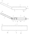
この実施例1の排水装置は、図1(a)〜(c)及び図2(a),(b)に示すように、平面視四辺形(正方形)の下部開口の容器状装置本体1と、圧縮空気を該容器状装置本体1の内部空間からその先端側に位置する排水口2に噴出させるノズル部3と、該排水口2から空気噴流及び排水対象水を外部に案内排出する排水案内管4とで構成したものである。
<Example 1>
As shown in FIGS. 1 (a) to 1 (c) and FIGS. 2 (a) and 2 (b), the drainage device according to the first embodiment includes a container-
前記容器状装置本体1は、図1(a)〜(c)及び図2(a)、(b)に示すように、上面を天板部1aで、周囲の四辺を下方に垂下する周側板1bで、それぞれ閉じ、かつ下部を全面的に開口した下部開口の箱形の部材である。該周側板1bの下端には、この実施例では、定間隔で複数の微小突起1bp、1bp…を突出させてある。これは、排水動作時に、該周側板1bの下端と排水対象部位の底面との間に微小隙間をあける手段であり、この微小空間を通じて排水対象水を外部から吸引させる趣旨の手段である。殆どの排水対象部位の底面は完全に平坦であるようなことはなく、若干の凹凸を有しているので、該周側板1bの下端にこのような微小突起1bp、1bp…を配さなくても、該下端と排水対象部位の底面との間には自ずと微小隙間が生じることになるが、例外的にあり得るかも知れない平坦な底面に対応するために構成したものである。
As shown in FIGS. 1 (a) to 1 (c) and FIGS. 2 (a) and 2 (b), the container-like device
なお、前記周側板1bの高さ寸法はできるだけ小さいのが好ましい。この容器状装置本体1は、前記ノズル部3から噴出される空気噴流の速さ及び量が同一であれば、その高さ寸法が小さいほど、排水能力は高くなる。
なおまた、この実施例では、この容器状装置本体1は、下部開口の平面視正方形の部材に構成したが、これに限定されず、平面視長方形、三角形又は五角形以上の多角形、円形、楕円形又は不定形に構成することも可能である。
The height of the
Further, in this embodiment, the container-
前記排水口2は、図1(b)に示すように、前記容器状装置本体1の先端側に開口した開口部であるが、先端側とは、該排水口2を開口させ、該排水口2に向かって空気噴流を噴出させるように構成したため、該排水口2を開口した部位がそうなったというべきものでもある。この排水口2は、この実施例では、前記周側板1bの一部に開口したが、前記天板部1aの一部に開口しても良いし、該周側板1bと該天板部1aの境界付近に開口することとしても良い。
As shown in FIG. 1 (b), the
前記排水案内管4は、図1(b)に示すように、前記排水口2に接続固定した剛性の管体であり、図1(a)、(b)及び図2(a)、(b)に示すように、該排水口2から斜め上向きに延長する構成としたものである。この排水案内管4の角度及び長さは、この排水装置を用いる排水対象部位から排水対象水を移送する移送先までの間の越えるべき障壁等の高さ及び距離を考慮して決定すべきものである。
As shown in FIG. 1 (b), the
前記排水口2及び前記排水案内管4の内径は、単位時間当たりの排水量を考慮して決定する。
The inner diameters of the
前記ノズル部3は、図1(b)及び図2(b)に示すように、この実施例では、その後部を前記容器状装置本体1の天板部1aの内面に固設したL型の固定片5で支持して、その先端部を前記排水口2中に延長挿入したものである。該ノズル部3の後端は、コンプレッサ8(図3(a)参照)に他端を接続したホース部材6の一端に接続し、該コンプレッサ8で生成した圧縮空気を該後端で受け入れ、先端から噴出できるようにしたものである。前記L型の固定片5は、その水平部を、前記のように、前記天板部1aの内面に溶接固定し、その垂直部に開口した取付孔に前記ノズル部3を貫通させ、その貫通前後に貫通させた固定部材で、該固定片5の垂直部に固定したものである。該ノズル部3の後端は、前記のように、ホース部材6を接続したものであるが、該ホース部材6はその一端を該ノズル部3の後端に外装し、その状態を締付手段で締め付けてその外装状態を固定したものである。該ホース部材6は、この実施例では、その途中を容器状装置本体1の後部側の周側板1bの一部に開口した貫通穴を通じて外部に引き出したものである。
As shown in FIGS. 1 (b) and 2 (b), the
この実施例1の排水装置は、以上のように構成したものであり、それ故、以下に述べるように、例えば、建築途上のベタ基礎7上に滞留した雨水等の排水対象水の排水に有用に使用することができる。
The drainage device according to the first embodiment is configured as described above. Therefore, as described below, for example, the drainage device is useful for draining water to be drained such as rainwater staying on the
この排水装置の使用に際しては、この装置を、まず排水対象水の滞留している排水対象部位、例えば、以上のような雨水の滞留したベタ基礎7上にセットする。このようなベタ基礎7上へのセットは、図3(b)に示すように、前記容器状装置本体1をその開口部を下にしてその周側板1bの下端を該ベタ基礎7上に当接状態して配置することにより行う。
When using this drainage device, this device is first set on the drainage target portion where the drainage target water stays, for example, the
前記排水案内管4は、その先端から排出される排水対象水が、図3(a)に示すように、直接に外部の側溝9等に投入されるか、側溝9等に向かって下降傾斜する傾斜路面に吐出されるか、または以上の二つの内のいずれかを次の段階で実行可能になる位置、例えば、図示しない基礎の立ち上がり部で区画された隣室のベタ基礎7上等に排水投入可能なように、向き及びその先端の位置を設定する。なお、該排水案内管4の先端の位置の以上のような状態のセットは、前記容器状装置本体1を必要な位置に移動することによって行うことになる。
As shown in FIG. 3 (a), the
このようにこの排水装置をセットして、前記コンプレッサ8を動作させると、該コンプレッサ8で圧縮空気が生成され、この圧縮空気が該コンプレッサ8に付属のタンクに蓄えられ、このタンクを介して排水装置に供給されることになる。該圧縮空気は、図3(a)に示すように、ホース部材6を通じて前記容器状装置本体1の内部に配置したノズル部3に供給される。図3(b)に示すように、該ノズル部3では、その後端で該圧縮空気を受け取り、そのホース部材6より小径の管状空間で増速して先端の噴口から噴出する。このようにして該ノズル部3の先端の憤口から噴出される高速の空気噴流により、該容器状装置本体1の内部に残留している空気及び内部に進入している滞留水が吸引され、これに伴って該容器状装置本体1の外部の滞留水が該容器状装置本体1の周側板1bの下端とベタ基礎7の表面との間の微小隙間を通じて該容器状装置本体1内に吸引される。
When the drainage device is set in this way and the
該ベタ基礎7等の排水対象水の滞留するエリアの殆どには何らかの凹凸があるので、周側板1bの下端との間には殆どの場合に微小隙間が生じるが、たとえ、例外的に、該ベタ基礎7の表面が全く平坦であったとしても、該周側板1bの下端には微小突起1bp、1bp…が形成してあるので、該周側板1bの下端と該ベタ基礎7の上面との間には必ず微小隙間が生じることになる。それ故、この微小隙間を通じた滞留水の吸引は確実に行われることになる。
Since most of the area where the water to be drained such as the
図3(b)に示すように、こうして該容器状装置本体1の外部の滞留水は、その内部に吸引され、前記空気噴流と共に前記排水口2に導かれ、これに接続した排水案内管4で案内され、隣室のベタ基礎7上、外部の側溝9内又はこれに繋がる傾斜路面上に排出されることになり、雨水等の滞留水の排水を行うことができる。隣室のベタ基礎7上等に排水した場合は、再度、この排水装置を用いて、同様に排水動作を行い、外部の側溝9等に排水する。
As shown in FIG. 3 (b), the staying water outside the container-
更に同図に示すように、水位が高く、水面wsが容器状装置本体1の天板部1aの上方に位置するような場合は、当然に、前記周側板1bとその下方のベタ基礎7の表面等との間の微小隙間を通じて滞留水の吸引排水動作が行われることになるが、排水動作に伴って水位が下がり、該微小隙間の上端の高さを下回る程度になっても、この隙間は、文字通りに、微小隙間なので、吸引排水動作は可能であり、良好に排水動作が継続されることになる。また排水動作が終了した後もその動作を継続すると、引き続いて排水後の排水対象部位の乾燥動作が行われることになる。
Further, as shown in the figure, in the case where the water level is high and the water surface ws is located above the top plate portion 1a of the container-like device
排水対象部位の水位が極めて低くなり、例えば、5mm程度以下になっても、前記のように、前記周側板1bの下端と排水対象部位の底面との間の間隔は微小隙間であり、具体的には、1mm前後又はそれ以下程度の非常に狭い隙間であるため、排水動作を継続することが可能になる。更に前記乾燥動作も可能になるものである。単位時間当たりの排水量は、容器状装置本体1を大サイズにすることで確保できることになる。勿論、サイズが大きくなれば、コンプレッサ8からの圧縮空気の量のも大きくなるが、その程度は、実験的に定めることができる。
Even if the water level of the drainage target portion becomes extremely low, for example, about 5 mm or less, as described above, the interval between the lower end of the
水位が低下してくると、吸引された滞留水は前記排水案内管4の先端から水滴状になって排出され、更に下回ると霧状になって排出されるようになる。ベタ基礎7上等の排水対象部位の底面が殆ど濡れているに過ぎない程度になった後は、以上の排水動作で該周側板1bの下端下の微小隙間を通じてその外部の空気が吸引されることになり、これによって該濡れた面上を空気が移動し、その乾燥を促進するようになる。
When the water level falls, the sucked-in retained water is discharged from the tip of the
排水対象部位であるベタ基礎7上に泥が残っていたような場合には、このエリアに水を投入し、かき混ぜて、泥水にし、この排水装置で排水動作を行うことにより、その泥水の排水を行うことができる。滞留水中に異物が混入していた場合は、それが前記周側板1bの下端下の微小隙間を通過できないものであれば、そこに詰まる等によって残留することになる。これらの詰まった異物は排水作業の終了後に容易に取り除くことができる。また容器状装置本体1の内部に入り込んだ異物は、排水案内管4の径が小さくはないので、これを通じて排出されることになる。異物がいずれかの部位に詰まって故障の原因になるようなことはない。
If mud remains on the
こうしてこの実施例1の排水装置によれば、排水対象部位の排水動作を容易確実に行うことが可能であり、かつ最後にはその部位の乾燥処理まで行うことが可能である。
なお、この実施例1の排水装置で砂利を敷設した領域の排水処理を行ったが、これも良好に実施できた。
Thus, according to the drainage device of the first embodiment, it is possible to easily and surely perform the draining operation of the drainage target part, and finally, it is possible to perform the drying process of the part.
In addition, although the drainage process of the area | region where the gravel was laid was performed with the drainage apparatus of this Example 1, this was also able to be implemented favorably.
<実施例2>
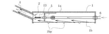
実施例2の排水装置は、図4に示すように、そのノズル部13が以上の実施例1のノズル部3と異なるのみで、他は全て同一である。図中、実施例1と同一の構成をもった要素にはそれと同一の符号を付してある。このノズル部13は、同図に示すように、その先端の噴口が前記排水口2の直前に位置し、実施例1のそれのように排水口2の内部まで進入していないものである。このノズル部13によれば、排水動作時に、その先端の噴口から噴出される空気噴流によって吸引される水流は、若干広がりつつ排水口2側に噴射流になって移動するが、その噴射流の全部が該排水口2中に入って行くことができる位置関係となっている。
<Example 2>
As shown in FIG. 4, the drainage device of the second embodiment is the same as the first embodiment except that the
従ってこの実施例2の排水装置は、実施例1の排水装置と同様に使用し、全く同様の効果を得ることができる。 Therefore, the drainage device of the second embodiment can be used in the same manner as the drainage device of the first embodiment, and the completely same effect can be obtained.
<実施例3>
実施例3の排水装置は、図5(a)に示すように、その容器状装置本体11を平面視円形に構成したものであり、それ故、天板部11aも平面視円形であり、周側板11bもまた底面視円弧状である。周側板11bの高さ寸法は実施例1の周側板1bと同様である。その他の構成要素は、図5(a)、(b)に示すように、全て実施例1のそれと同一であり、同一の符号を用いている。
<Example 3>
As shown in FIG. 5 (a), the drainage device of Example 3 is configured such that its container-
従ってこの実施例3の排水装置は、実施例1の排水装置と同様に使用した場合に、排水対象部位の滞留水を周側板11bの下端下の微小隙間を通じて吸引排水することができるものであり、その滞留水の流れ方は実施例1におけるそれと若干は異なったものとなるが、実質的に同様に排水動作を行うことができる。その後の乾燥動作もまた同様である。
Therefore, when the drainage device of this
<実施例4>
実施例4の排水装置は、図6(a)〜(c)に示すように、ノズル部3に接続するホース部材16の通過経路が実施例1のそれと異なる他は、実施例1の排水装置と全く同様の構成である。図6中では、実施例1の構成要素と同様の構成の構成要素には同一の符号を付してある。
<Example 4>
As shown in FIGS. 6A to 6C, the drainage device of the fourth embodiment is the same as that of the first embodiment except that the passage route of the
この実施例4では、コンプレッサ8に付属のタンクに一端を接続したホース部材16は、同図に示すように、容器状装置本体1の前部側で周側板1bを通じてその内部に導かれ、後方に途中まで延長した上で、折り返して前記ノズル部3の後端に接続されている。接続の仕方は実施例1のそれと同様である。
In the fourth embodiment, the
実施例1と異なっているのは、以上のように、前記ホース部材16の通過経路のみであるから、この排水装置を、排水対象部位の滞留水の排水のために使用した場合は、当然ながら、同様に動作し同様の効果を得ることができる。すなわち、この排水装置の容器状装置本体1を排水対象部位に設置して排水動作をさせると、言うまでも無く、排水対象部位の滞留水は周側板1bの下端下の微小隙間を通じて吸引排水されることになり、ホース部材16の位置関係が実施例1のそれとは若干異なるので、排水動作に伴う滞留水の流れ方は、実施例1におけるそれと若干異なったものとなるが、実質的には同様の排水動作を行うことができる。その後の乾燥動作もまた同様である。
As described above, since only the passage path of the
ただし、この実施例4では、前記ホース部材16を排水案内管4と同様に、容器状装置本体1の周側板1bの前側部分から外部に引き出しており、多くの場合は、コンプレッサ8は、排水案内管4の延長側に配置されているので、その関係上から、排水対象部位への設置の際に好都合な場合が多い。
However, in the fourth embodiment, the
<実施例5>
実施例5は、図7(a)、(b)及び図8(a)、(b)に示すように、容器状装置本体21の周側板21bの高さ方向の寸法及び排水案内管24の周側板21bへの取付角度及びノズル部23の先端の位置のそれぞれが実施例1のそれらと異なるほかは、実施例1のそれらと全く同様の構成である。それ故、実施例1のそれぞれと同一構成要素には同一の符号を付してある。
<Example 5>
In the fifth embodiment, as shown in FIGS. 7A and 7B and FIGS. 8A and 8B, the dimensions in the height direction of the
前記周側板21bは、特に図7(a)、(b)に示すように、前部のそれの高さ寸法を高く構成し、後部のそれを低く構成し、両側部のそれを前後のそれを繋ぐ傾斜状に構成したものである。これ以外の容器状装置本体21の構成は、実施例1の容器状装置本体1と同様である。また前記排水案内管24は、それ自体は、実施例1の排水案内管4と全く同様の構成であるが、容器状装置本体21の前部の周側板21bへの取り付け方を、該周側板21bの面に対して直角に突出するように構成したものである。更に前記ノズル部23は排水口2の直前まで直線状に延長したものである。該ノズル部23の先端の噴口は、以上に述べ、図7(b)及び図8(b)に示すように、排水口2の直前に位置し、該ノズル部23の先端の噴口から噴出される空気噴流に伴って徐々に拡大しつつ移動する排水噴流が生じるが、上記ノズル部23の先端噴口の排水口2との位置関係は、該排水噴流の全てが該排水口2に流入するような距離関係としてあるものである。
As shown in FIGS. 7 (a) and 7 (b), the
従ってこの実施例5の容器状装置本体21を平面である排水対象部位の底面上に設置すると、前部側の周側板21bの高さ寸法が高いので、該周側板21の外面が上向きの傾斜面となり、自ずと前記排水案内管24もその先端に向かって上向き傾斜となる。例えば、建築途上の建築物のベタ基礎7上に滞留した雨水を排水する際には、周囲の基礎立ち上がり部を越えて排水することが可能になる。
Therefore, when the container-like device
従ってこの実施例5の排水装置によれば、実施例1と殆ど同様に使用して同様の効果を得ることができる。 Therefore, according to the drainage device of the fifth embodiment, the same effect can be obtained by using it almost in the same manner as the first embodiment.
<実施例6>
実施例6は、図9(a)〜(c)に示すように、容器状装置本体31へのノズル部33及びホース部材36の取り付け方並びに排水案内管34の容器状装置本体31への取り付け方、更に容器状装置本体31の周側板31bの高さ寸法が小さいことのそれぞれが実施例1のそれらと異なる他は、実施例1のそれらと全く同様の構成である。
<Example 6>
In Example 6, as shown in FIGS. 9A to 9C, the
前記ノズル部33は、図9(a)〜(c)に示すように、容器状装置本体31の天板部31aの下面にスペーサ板35aを固設した上で、その下面に当接状態に配置し、該ノズル部33を取付部材35bで該スペーサ板35aに固設する。この固設は、該ノズル部33を、中央部の部分円弧状凹部35b1で抱え、その両側の取付板35b2、35b2を該スペーサ板35aに各々溶接固定することにより行ったものである。
As shown in FIGS. 9A to 9C, the
図9(a)、(b)に示すように、ホース部材36も、サイズの若干大きな同様の部材で固定する。すなわち、該ホース部材36は、容器状装置本体31の天板部31aの下面にスペーサ板35cを固設した上で、その下面に当接状態に配置し、該ホース部材36を取付部材35dで該スペーサ板35cの下面に固設する。この固設は、該ホース部材36を、中央部の部分円弧状凹部35d1で抱え、その両側の取付板35d2、35d2を該スペーサ板35cに各々溶接固定することにより行ったものである。
As shown in FIGS. 9A and 9B, the
前記排水案内管34は、図9(a)、(b)に示すように、容器状装置本体31の天板部31aから周側板31bに跨がった位置にその基部を固設し、急角度で立ち上げたものである。排水口32も当然に該基部に対応する位置に開口したものである。そして又前記ノズル部33の先端の噴口は該排水口32中に進入状態に配したものである。
As shown in FIGS. 9 (a) and 9 (b), the
それ故、この実施例6による排水装置では、以上のように、ノズル部33及びホース部材36を、前記のようにして天板部31aに取り付けたため、前記容器状部材31の周側板31bの高さ方向の寸法を低くすることが可能になり、この実施例6では、そのように可能なだけ低く構成したものである。
Therefore, in the drainage device according to the sixth embodiment, as described above, since the
従ってこの実施例6の排水装置によれば、実施例1〜5と殆ど同様に使用して排水対象部位の排水処理を行うことが可能であり、他の実施例1〜5と同様の圧縮空気に関する条件のもとでは、より多量の排水処理をより効率的に行うことができる。 Therefore, according to the drainage device of the sixth embodiment, it is possible to perform the drainage treatment of the drainage target site using almost the same as in the first to fifth embodiments, and the compressed air similar to the other first to fifth embodiments. Under such conditions, a larger amount of wastewater treatment can be performed more efficiently.
本発明の排水装置は、これを製造する工業分野及びこれを用いる排水処理の分野で利用することができる。 The drainage device of the present invention can be used in the industrial field for producing it and in the field of wastewater treatment using the same.
1 容器状装置本体
1a 天板部
1b 周側板
1bp 微小突起
2 排水口
3 ノズル部
4 排水案内管
5 L型の固定片
6 ホース部材
7 ベタ基礎
8 コンプレッサ
9 側溝
11 容器状装置本体
11a 天板部
11b 周側板
13 ノズル部
16 ホース部材
21 容器状装置本体
21a 天板部
21b 周側板
23 ノズル部
24 排水案内管
31 容器状装置本体
31a 天板部
31b 周側板
31bp 微小突起
32 排水口
33 ノズル部
34 排水案内管
35a スペーサ板
35b 取付部材
35b1 部分円弧状凹部
35b2 取付板
35c スペーサ板
35d 取付部材
35d1 部分円弧状凹部
35d2 取付板
36 ホース部材
ws 水面
DESCRIPTION OF
Claims (2)
Priority Applications (1)
| Application Number | Priority Date | Filing Date | Title |
|---|---|---|---|
| JP2013024319A JP6281803B2 (en) | 2013-02-12 | 2013-02-12 | Drainage equipment |
Applications Claiming Priority (1)
| Application Number | Priority Date | Filing Date | Title |
|---|---|---|---|
| JP2013024319A JP6281803B2 (en) | 2013-02-12 | 2013-02-12 | Drainage equipment |
Publications (2)
| Publication Number | Publication Date |
|---|---|
| JP2014152728A JP2014152728A (en) | 2014-08-25 |
| JP6281803B2 true JP6281803B2 (en) | 2018-02-21 |
Family
ID=51574821
Family Applications (1)
| Application Number | Title | Priority Date | Filing Date |
|---|---|---|---|
| JP2013024319A Active JP6281803B2 (en) | 2013-02-12 | 2013-02-12 | Drainage equipment |
Country Status (1)
| Country | Link |
|---|---|
| JP (1) | JP6281803B2 (en) |
Families Citing this family (2)
| Publication number | Priority date | Publication date | Assignee | Title |
|---|---|---|---|---|
| JP7378710B2 (en) * | 2018-11-12 | 2023-11-14 | 株式会社サーフェステクノロジー | Wastewater suction recovery device |
| JP6739887B1 (en) * | 2019-12-20 | 2020-08-12 | 正通 亀井 | Secondary drainage method in case of flood damage |
Family Cites Families (7)
| Publication number | Priority date | Publication date | Assignee | Title |
|---|---|---|---|---|
| JPS4833045Y1 (en) * | 1970-08-26 | 1973-10-08 | ||
| JPS5430099U (en) * | 1977-08-02 | 1979-02-27 | ||
| JPS54126202U (en) * | 1978-02-23 | 1979-09-03 | ||
| JPS57144300U (en) * | 1981-03-04 | 1982-09-10 | ||
| JPH0329597Y2 (en) * | 1986-10-01 | 1991-06-24 | ||
| JPH08303399A (en) * | 1995-05-01 | 1996-11-19 | Ogawa Jidosha:Kk | Method and device for sucking sludge water at ultra high lift by vacuum pump unit |
| JP2012233447A (en) * | 2011-05-06 | 2012-11-29 | Ihi Corp | Submersible pump device |
-
2013
- 2013-02-12 JP JP2013024319A patent/JP6281803B2/en active Active
Also Published As
| Publication number | Publication date |
|---|---|
| JP2014152728A (en) | 2014-08-25 |
Similar Documents
| Publication | Publication Date | Title |
|---|---|---|
| JP5179159B2 (en) | Sand lifting equipment | |
| JP2008086997A5 (en) | ||
| JP3620670B2 (en) | Circulating drainage device for sewage pipe work | |
| US11719238B2 (en) | Liquid intake filters | |
| US20140202941A1 (en) | Whirlpool skimmer | |
| JP2010036151A (en) | Sand pumping apparatus | |
| US8728307B2 (en) | Whirlpool skimmer | |
| JP6281803B2 (en) | Drainage equipment | |
| KR20170100798A (en) | Vacuum well drainage system for underground water level lowering | |
| JP5875148B2 (en) | Sanding method and sedimentation equipment | |
| KR101463223B1 (en) | Apparatus and method for removing local emission and precipitated sand of underground water excavation and geothermal heat excavation | |
| JP2016156243A (en) | Side ditch drainage device | |
| KR102145976B1 (en) | Steel pole for mobile communication and construction method thereof | |
| JP2000126514A (en) | Sludge withdrawal device of wastewater treatment tank | |
| JP2013202570A (en) | Sand collection nozzle and sand collection nozzle device | |
| JP6313113B2 (en) | Method and apparatus for sucking up sediment from well bottom | |
| JP5872960B2 (en) | Structure of Kamaba | |
| US4797028A (en) | Beaver control siphon apparatus | |
| KR100713212B1 (en) | A discharge facilities for sediment in sewage box | |
| JP2014076449A (en) | Sand pumping method | |
| JP5808008B2 (en) | Suction force generator and vacuum consolidation ground improvement method | |
| CN109458146A (en) | Hole cleaning device for the big partial size sediment in priming concrete pile hole bottom | |
| JP6027868B2 (en) | Sand lifting equipment | |
| CN215829459U (en) | Underground water discharge device around working well | |
| JP2005111383A (en) | Sand collecting tank |
Legal Events
| Date | Code | Title | Description |
|---|---|---|---|
| RD04 | Notification of resignation of power of attorney |
Free format text: JAPANESE INTERMEDIATE CODE: A7424 Effective date: 20140520 |
|
| A621 | Written request for application examination |
Free format text: JAPANESE INTERMEDIATE CODE: A621 Effective date: 20160114 |
|
| A977 | Report on retrieval |
Free format text: JAPANESE INTERMEDIATE CODE: A971007 Effective date: 20160920 |
|
| A131 | Notification of reasons for refusal |
Free format text: JAPANESE INTERMEDIATE CODE: A131 Effective date: 20161011 |
|
| A131 | Notification of reasons for refusal |
Free format text: JAPANESE INTERMEDIATE CODE: A131 Effective date: 20170411 |
|
| A521 | Written amendment |
Free format text: JAPANESE INTERMEDIATE CODE: A523 Effective date: 20170526 |
|
| A521 | Written amendment |
Free format text: JAPANESE INTERMEDIATE CODE: A523 Effective date: 20170703 |
|
| TRDD | Decision of grant or rejection written | ||
| A01 | Written decision to grant a patent or to grant a registration (utility model) |
Free format text: JAPANESE INTERMEDIATE CODE: A01 Effective date: 20180109 |
|
| A61 | First payment of annual fees (during grant procedure) |
Free format text: JAPANESE INTERMEDIATE CODE: A61 Effective date: 20180112 |
|
| R150 | Certificate of patent or registration of utility model |
Ref document number: 6281803 Country of ref document: JP Free format text: JAPANESE INTERMEDIATE CODE: R150 |
|
| R250 | Receipt of annual fees |
Free format text: JAPANESE INTERMEDIATE CODE: R250 |