JP6281521B2 - Image processing apparatus and method, recording medium, and program - Google Patents
Image processing apparatus and method, recording medium, and program Download PDFInfo
- Publication number
- JP6281521B2 JP6281521B2 JP2015077536A JP2015077536A JP6281521B2 JP 6281521 B2 JP6281521 B2 JP 6281521B2 JP 2015077536 A JP2015077536 A JP 2015077536A JP 2015077536 A JP2015077536 A JP 2015077536A JP 6281521 B2 JP6281521 B2 JP 6281521B2
- Authority
- JP
- Japan
- Prior art keywords
- layer
- prediction
- inter
- unit
- image
- Prior art date
- Legal status (The legal status is an assumption and is not a legal conclusion. Google has not performed a legal analysis and makes no representation as to the accuracy of the status listed.)
- Active
Links
Images


Classifications
-
- H—ELECTRICITY
- H04—ELECTRIC COMMUNICATION TECHNIQUE
- H04N—PICTORIAL COMMUNICATION, e.g. TELEVISION
- H04N19/00—Methods or arrangements for coding, decoding, compressing or decompressing digital video signals
- H04N19/10—Methods or arrangements for coding, decoding, compressing or decompressing digital video signals using adaptive coding
- H04N19/102—Methods or arrangements for coding, decoding, compressing or decompressing digital video signals using adaptive coding characterised by the element, parameter or selection affected or controlled by the adaptive coding
- H04N19/103—Selection of coding mode or of prediction mode
-
- H—ELECTRICITY
- H04—ELECTRIC COMMUNICATION TECHNIQUE
- H04N—PICTORIAL COMMUNICATION, e.g. TELEVISION
- H04N19/00—Methods or arrangements for coding, decoding, compressing or decompressing digital video signals
- H04N19/30—Methods or arrangements for coding, decoding, compressing or decompressing digital video signals using hierarchical techniques, e.g. scalability
- H04N19/34—Scalability techniques involving progressive bit-plane based encoding of the enhancement layer, e.g. fine granular scalability [FGS]
-
- H—ELECTRICITY
- H04—ELECTRIC COMMUNICATION TECHNIQUE
- H04N—PICTORIAL COMMUNICATION, e.g. TELEVISION
- H04N19/00—Methods or arrangements for coding, decoding, compressing or decompressing digital video signals
- H04N19/10—Methods or arrangements for coding, decoding, compressing or decompressing digital video signals using adaptive coding
- H04N19/102—Methods or arrangements for coding, decoding, compressing or decompressing digital video signals using adaptive coding characterised by the element, parameter or selection affected or controlled by the adaptive coding
- H04N19/103—Selection of coding mode or of prediction mode
- H04N19/105—Selection of the reference unit for prediction within a chosen coding or prediction mode, e.g. adaptive choice of position and number of pixels used for prediction
-
- H—ELECTRICITY
- H04—ELECTRIC COMMUNICATION TECHNIQUE
- H04N—PICTORIAL COMMUNICATION, e.g. TELEVISION
- H04N19/00—Methods or arrangements for coding, decoding, compressing or decompressing digital video signals
- H04N19/10—Methods or arrangements for coding, decoding, compressing or decompressing digital video signals using adaptive coding
- H04N19/134—Methods or arrangements for coding, decoding, compressing or decompressing digital video signals using adaptive coding characterised by the element, parameter or criterion affecting or controlling the adaptive coding
- H04N19/146—Data rate or code amount at the encoder output
- H04N19/147—Data rate or code amount at the encoder output according to rate distortion criteria
-
- H—ELECTRICITY
- H04—ELECTRIC COMMUNICATION TECHNIQUE
- H04N—PICTORIAL COMMUNICATION, e.g. TELEVISION
- H04N19/00—Methods or arrangements for coding, decoding, compressing or decompressing digital video signals
- H04N19/10—Methods or arrangements for coding, decoding, compressing or decompressing digital video signals using adaptive coding
- H04N19/134—Methods or arrangements for coding, decoding, compressing or decompressing digital video signals using adaptive coding characterised by the element, parameter or criterion affecting or controlling the adaptive coding
- H04N19/157—Assigned coding mode, i.e. the coding mode being predefined or preselected to be further used for selection of another element or parameter
- H04N19/159—Prediction type, e.g. intra-frame, inter-frame or bidirectional frame prediction
-
- H—ELECTRICITY
- H04—ELECTRIC COMMUNICATION TECHNIQUE
- H04N—PICTORIAL COMMUNICATION, e.g. TELEVISION
- H04N19/00—Methods or arrangements for coding, decoding, compressing or decompressing digital video signals
- H04N19/10—Methods or arrangements for coding, decoding, compressing or decompressing digital video signals using adaptive coding
- H04N19/169—Methods or arrangements for coding, decoding, compressing or decompressing digital video signals using adaptive coding characterised by the coding unit, i.e. the structural portion or semantic portion of the video signal being the object or the subject of the adaptive coding
- H04N19/17—Methods or arrangements for coding, decoding, compressing or decompressing digital video signals using adaptive coding characterised by the coding unit, i.e. the structural portion or semantic portion of the video signal being the object or the subject of the adaptive coding the unit being an image region, e.g. an object
- H04N19/172—Methods or arrangements for coding, decoding, compressing or decompressing digital video signals using adaptive coding characterised by the coding unit, i.e. the structural portion or semantic portion of the video signal being the object or the subject of the adaptive coding the unit being an image region, e.g. an object the region being a picture, frame or field
-
- H—ELECTRICITY
- H04—ELECTRIC COMMUNICATION TECHNIQUE
- H04N—PICTORIAL COMMUNICATION, e.g. TELEVISION
- H04N19/00—Methods or arrangements for coding, decoding, compressing or decompressing digital video signals
- H04N19/10—Methods or arrangements for coding, decoding, compressing or decompressing digital video signals using adaptive coding
- H04N19/169—Methods or arrangements for coding, decoding, compressing or decompressing digital video signals using adaptive coding characterised by the coding unit, i.e. the structural portion or semantic portion of the video signal being the object or the subject of the adaptive coding
- H04N19/187—Methods or arrangements for coding, decoding, compressing or decompressing digital video signals using adaptive coding characterised by the coding unit, i.e. the structural portion or semantic portion of the video signal being the object or the subject of the adaptive coding the unit being a scalable video layer
-
- H—ELECTRICITY
- H04—ELECTRIC COMMUNICATION TECHNIQUE
- H04N—PICTORIAL COMMUNICATION, e.g. TELEVISION
- H04N19/00—Methods or arrangements for coding, decoding, compressing or decompressing digital video signals
- H04N19/30—Methods or arrangements for coding, decoding, compressing or decompressing digital video signals using hierarchical techniques, e.g. scalability
- H04N19/31—Methods or arrangements for coding, decoding, compressing or decompressing digital video signals using hierarchical techniques, e.g. scalability in the temporal domain
-
- H—ELECTRICITY
- H04—ELECTRIC COMMUNICATION TECHNIQUE
- H04N—PICTORIAL COMMUNICATION, e.g. TELEVISION
- H04N19/00—Methods or arrangements for coding, decoding, compressing or decompressing digital video signals
- H04N19/44—Decoders specially adapted therefor, e.g. video decoders which are asymmetric with respect to the encoder
-
- H—ELECTRICITY
- H04—ELECTRIC COMMUNICATION TECHNIQUE
- H04N—PICTORIAL COMMUNICATION, e.g. TELEVISION
- H04N19/00—Methods or arrangements for coding, decoding, compressing or decompressing digital video signals
- H04N19/50—Methods or arrangements for coding, decoding, compressing or decompressing digital video signals using predictive coding
- H04N19/503—Methods or arrangements for coding, decoding, compressing or decompressing digital video signals using predictive coding involving temporal prediction
- H04N19/51—Motion estimation or motion compensation
- H04N19/513—Processing of motion vectors
- H04N19/517—Processing of motion vectors by encoding
- H04N19/52—Processing of motion vectors by encoding by predictive encoding
-
- H—ELECTRICITY
- H04—ELECTRIC COMMUNICATION TECHNIQUE
- H04N—PICTORIAL COMMUNICATION, e.g. TELEVISION
- H04N19/00—Methods or arrangements for coding, decoding, compressing or decompressing digital video signals
- H04N19/70—Methods or arrangements for coding, decoding, compressing or decompressing digital video signals characterised by syntax aspects related to video coding, e.g. related to compression standards
Landscapes
- Engineering & Computer Science (AREA)
- Multimedia (AREA)
- Signal Processing (AREA)
- Compression Or Coding Systems Of Tv Signals (AREA)
- Compression, Expansion, Code Conversion, And Decoders (AREA)
- Medicines Containing Antibodies Or Antigens For Use As Internal Diagnostic Agents (AREA)
Description
本開示は画像処理装置および方法、記録媒体、並びに、プログラムに関し、特に、符号化効率の低減を抑制することができるようにした画像処理装置および方法、記録媒体、並びに、プログラムに関する。 The present disclosure relates to an image processing apparatus and method, a recording medium, and a program, and more particularly, to an image processing apparatus and method, a recording medium, and a program that can suppress a reduction in encoding efficiency.
近年、画像情報をデジタルとして取り扱い、その際、効率の高い情報の伝送、蓄積を目的とし、画像情報特有の冗長性を利用して、離散コサイン変換等の直交変換と動き補償により圧縮する符号化方式を採用して画像を圧縮符号する装置が普及しつつある。この符号化方式には、例えば、MPEG(Moving Picture Experts Group)などがある。 In recent years, image information has been handled as digital data, and at that time, for the purpose of efficient transmission and storage of information, encoding is performed by orthogonal transform such as discrete cosine transform and motion compensation using redundancy unique to image information. An apparatus that employs a method to compress and code an image is becoming widespread. This encoding method includes, for example, MPEG (Moving Picture Experts Group).
特に、MPEG2(ISO/IEC 13818-2)は、汎用画像符号化方式として定義されており、飛び越し走査画像及び順次走査画像の双方、並びに標準解像度画像及び高精細画像を網羅する標準である。例えば、MPEG2は、プロフェッショナル用途及びコンシューマ用途の広範なアプリケーションに現在広く用いられている。MPEG2圧縮方式を用いることにより、例えば720×480画素を持つ標準解像度の飛び越し走査画像であれば4乃至8Mbpsの符号量(ビットレート)が割り当てられる。また、MPEG2圧縮方式を用いることにより、例えば1920×1088画素を持つ高解像度の飛び越し走査画像であれば18乃至22 Mbpsの符号量(ビットレート)が割り当てられる。これにより、高い圧縮率と良好な画質の実現が可能である。 In particular, MPEG2 (ISO / IEC 13818-2) is defined as a general-purpose image coding system, and is a standard that covers both interlaced scanning images and progressive scanning images, as well as standard resolution images and high-definition images. For example, MPEG2 is currently widely used in a wide range of applications for professional and consumer applications. By using the MPEG2 compression method, for example, a code amount (bit rate) of 4 to 8 Mbps is assigned to an interlaced scanned image having a standard resolution of 720 × 480 pixels. Further, by using the MPEG2 compression method, for example, in the case of a high-resolution interlaced scanned image having 1920 × 1088 pixels, a code amount (bit rate) of 18 to 22 Mbps is allocated. As a result, a high compression rate and good image quality can be realized.
MPEG2は主として放送用に適合する高画質符号化を対象としていたが、MPEG1より低い符号量(ビットレート)、つまりより高い圧縮率の符号化方式には対応していなかった。携帯端末の普及により、今後そのような符号化方式のニーズは高まると思われ、これに対応してMPEG4符号化方式の標準化が行われた。画像符号化方式に関しては、1998年12月にISO/IEC 14496-2としてその規格が国際標準に承認された。 MPEG2 was mainly intended for high-quality encoding suitable for broadcasting, but did not support encoding methods with a lower code amount (bit rate) than MPEG1, that is, a higher compression rate. With the widespread use of mobile terminals, the need for such an encoding system is expected to increase in the future, and the MPEG4 encoding system has been standardized accordingly. Regarding the image coding system, the standard was approved as an international standard as ISO / IEC 14496-2 in December 1998.
更に、近年、当初テレビ会議用の画像符号化を目的として、H.26L (ITU-T(International Telecommunication Union Telecommunication Standardization Sector) Q6/16 VCEG(Video Coding Expert Group))という標準の規格化が進められた。H.26LはMPEG2やMPEG4といった従来の符号化方式に比べ、その符号化、復号化により多くの演算量が要求されるものの、より高い符号化効率が実現されることが知られている。また、現在、MPEG4の活動の一環として、このH.26Lをベースに、H.26Lではサポートされない機能をも取り入れ、より高い符号化効率を実現する標準化がJoint Model of Enhanced-Compression Video Codingとして行われた。 Furthermore, in recent years, the standardization of the standard called H.26L (ITU-T (International Telecommunication Union Telecommunication Standardization Sector) Q6 / 16 Video Coding Expert Group (VCEG)) has been promoted for the purpose of initial video coding for video conferencing. It was. H.26L is known to achieve higher encoding efficiency than the conventional encoding schemes such as MPEG2 and MPEG4, although a large amount of calculation is required for encoding and decoding. Currently, as part of MPEG4 activities, standardization to achieve higher coding efficiency based on this H.26L and incorporating functions not supported by H.26L is performed as Joint Model of Enhanced-Compression Video Coding. It was broken.
標準化のスケジュールとしては、2003年3月にはH.264及びMPEG-4 Part10 (Advanced Video Coding、以下AVCと記す)という名の元に国際標準となった。 The standardization schedule became an international standard in March 2003 under the names of H.264 and MPEG-4 Part 10 (Advanced Video Coding, hereinafter referred to as AVC).
さらに、このH.264/AVCの拡張として、RGBや4:2:2、4:4:4といった、業務用に必要な符号化ツールや、MPEG-2で規定されていた8x8DCTや量子化マトリクスをも含んだFRExt (Fidelity Range Extension) の標準化が2005年2月に完了した。これにより、H.264/AVCを用いて、映画に含まれるフィルムノイズをも良好に表現することが可能な符号化方式となって、Blu-Ray Disc(商標)等の幅広いアプリケーションに用いられる運びとなった。 Furthermore, this H.C. As an extension of H.264 / AVC, FRExt including RGB, 4: 2: 2, 4: 4: 4 coding tools necessary for business use, 8x8DCT and quantization matrix defined by MPEG-2 (Fidelity Range Extension) standardization was completed in February 2005. As a result, H.C. Using 264 / AVC, it became an encoding method that can express film noise contained in movies well, and it has been used in a wide range of applications such as Blu-Ray Disc (trademark).
しかしながら、昨今、ハイビジョン画像の4倍の、4000×2000画素程度の画像を圧縮したい、あるいは、インターネットのような、限られた伝送容量の環境において、ハイビジョン画像を配信したいといった、更なる高圧縮率符号化に対するニーズが高まっている。このため、先述の、ITU-T傘下のVCEGにおいて、符号化効率の改善に関する検討が継続され行なわれている。 However, these days, we want to compress images with a resolution of 4000 x 2000 pixels, which is four times higher than high-definition images, or deliver high-definition images in a limited transmission capacity environment such as the Internet. There is a growing need for encoding. For this reason, in the above-mentioned VCEG under the ITU-T, studies on improving the coding efficiency are being continued.
そこで、現在、AVCより更なる符号化効率の向上を目的として、ITU-Tと、ISO/IECの共同の標準化団体であるJCTVC(Joint Collaboration Team - Video Coding)により、HEVC(High Efficiency Video Coding)と呼ばれる符号化方式の標準化が進められている。HEVC規格については、2012年2月に最初のドラフト版仕様であるCommittee draftが発行されている(例えば、非特許文献1参照)。 Therefore, for the purpose of further improving the encoding efficiency compared to AVC, HEVC (High Efficiency Video Coding) is being developed by JCTVC (Joint Collaboration Team-Video Coding), a joint standardization organization of ITU-T and ISO / IEC. The standardization of the encoding method called is being advanced. Regarding the HEVC standard, a Committee draft, which is the first draft version specification, was issued in February 2012 (see, for example, Non-Patent Document 1).
ところで、これまでの、MPEG-2やAVCといった画像符号化方式は、画像を複数のレイヤに階層化して符号化するスケーラビリティ(scalability)機能を有していた。 By the way, the conventional image encoding methods such as MPEG-2 and AVC have a scalability function for encoding an image by layering a plurality of layers.
すなわち、例えば携帯電話のような、処理能力の低い端末に対しては、ベースレイヤ(base layer)のみの画像圧縮情報を伝送し、空間時間解像度の低い、或いは、画質の良くない動画像を再生し、テレビやパーソナルコンピュータのような、処理能力の高い端末に対しては、ベースレイヤ(base layer)に加えて、エンハンスメントレイヤ(enhancement layer)の画像圧縮情報を伝送し、空間時間解像度の高い、或いは、画質の高い動画像を再生するといったように、トランスコード処理を行うことなく、端末やネットワークの能力に応じた画像圧縮情報を、サーバから送信することが可能となる。 In other words, for a terminal with low processing capability, such as a mobile phone, image compression information of only the base layer is transmitted, and a moving image with low spatiotemporal resolution or poor image quality is played However, for terminals with high processing capability such as televisions and personal computers, in addition to the base layer (base layer), image compression information of the enhancement layer (enhancement layer) is transmitted, and the spatial and temporal resolution is high. Alternatively, it is possible to transmit image compression information according to the capabilities of the terminal and the network from the server without performing transcoding processing, such as playing a moving image with high image quality.
ところで、スケーラブル符号化を行う際、全てのピクチャにおいて、階層間での予測処理を行うことは、演算量の増大に繋がる。 By the way, when performing scalable coding, performing prediction processing between hierarchies in all pictures leads to an increase in the amount of calculation.
そこで、ピクチャ(Picture)毎に階層間の予測処理のオン/オフ(on/off)を、NALユニット(NAL_Unit)において指定することが提案された(例えば、非特許文献2参照)。
Therefore, it has been proposed to specify on / off of prediction processing between layers in each NAL unit (NAL_Unit) for each picture (see Non-Patent
しかしながら、従来の方法では、このような、階層間の予測処理のオン/オフ(on/off)を制御する情報は、ピクチャ毎に生成され、伝送された。そのため、この情報の伝送により符号量が増大し、符号化効率が低減する恐れがあった。 However, in the conventional method, such information for controlling on / off of prediction processing between layers is generated and transmitted for each picture. For this reason, the transmission of this information increases the amount of codes, which may reduce the coding efficiency.
本開示は、このような状況に鑑みてなされたものであり、符号化効率の低減を抑制することができるようにするものである。 This indication is made in view of such a situation, and makes it possible to control reduction of coding efficiency.
本技術の一側面は、複数のレイヤを有する画像の前記複数のレイヤ間の予測であるレイヤ間予測を行う最上位のサブレイヤを決定するレイヤ間予測制御情報に基づいて、最下位のサブレイヤから前記レイヤ間予測制御情報により決定される前記最上位のサブレイヤまで前記レイヤ間予測を行うようにして、前記画像を符号化する符号化部を備える画像処理装置である。 According to an embodiment of the present technology, based on the inter-layer prediction control information for determining a plurality of top-level sublayer performing a is inter-layer prediction inter-layer prediction image having a plurality of layers, wherein the lowermost sublayer The image processing apparatus includes an encoding unit that encodes the image such that the inter-layer prediction is performed up to the highest sublayer determined by inter-layer prediction control information .
前記符号化部は、カレントレイヤのカレントピクチャが、前記レイヤ間予測制御情報により前記レイヤ間予測を行うように決定されるサブレイヤに属する場合、前記カレントピクチャの画像を、前記レイヤ間予測を用いて符号化することができる。 The encoding unit, when the current picture of the current layer belongs to a sub-layer determined to perform the inter-layer prediction according to the inter-layer prediction control information, the image of the current picture using the inter-layer prediction Can be encoded.
前記レイヤ間予測制御情報は、レイヤ毎に設定されるようにすることができる。 The inter-layer prediction control information can be set for each layer.
前記レイヤ間予測制御情報は、全レイヤ共通のパラメータとして設定されるようにすることができる。 The inter-layer prediction control information can be set as a parameter common to all layers.
前記符号化部により符号化された前記画像の符号化データと、前記レイヤ間予測制御情報とを伝送する伝送部をさらに備えることができる。 The image processing apparatus may further include a transmission unit that transmits the encoded data of the image encoded by the encoding unit and the inter-layer prediction control information.
前記符号化部は、前記レイヤ間予測制御情報として設定された、前記複数のレイヤ間のピクセル予測であるレイヤ間ピクセル予測を行うかを制御するレイヤ間ピクセル予測制御情報に基づいて前記レイヤ間ピクセル予測を行い、前記レイヤ間予測制御情報として、前記レイヤ間ピクセル予測制御情報とは独立に設定された、前記複数のレイヤ間のシンタクス予測であるレイヤ間シンタクス予測を行うかを制御するレイヤ間シンタクス予測制御情報に基づいて前記レイヤ間シンタクス予測を行い、前記伝送部は、前記レイヤ間予測制御情報として、互いに独立に設定された前記レイヤ間ピクセル予測制御情報および前記レイヤ間シンタクス予測制御情報を伝送することができる。 The encoding unit sets the inter-layer pixel based on inter-layer pixel prediction control information that is set as the inter-layer prediction control information and controls whether to perform inter-layer pixel prediction that is pixel prediction between the plurality of layers. Inter-layer syntax for performing prediction and controlling whether to perform inter-layer syntax prediction that is syntax prediction between the plurality of layers set independently of the inter-layer pixel prediction control information as the inter-layer prediction control information The inter-layer syntax prediction is performed based on prediction control information, and the transmission unit transmits the inter-layer pixel prediction control information and the inter-layer syntax prediction control information set independently of each other as the inter-layer prediction control information. can do.
前記レイヤ間ピクセル予測制御情報は、前記レイヤ間ピクセル予測を行うかを、前記サブレイヤを用いて制御し、前記符号化部は、前記レイヤ間ピクセル予測制御情報により決定されるサブレイヤのみ前記レイヤ間ピクセル予測を行い、前記レイヤ間シンタクス予測制御情報は、前記レイヤ間シンタクス予測を行うかを、ピクチャ若しくはスライス毎に制御し、前記符号化部は、前記レイヤ間シンタクス予測制御情報により決定されるピクチャ若しくはスライスのみ前記レイヤ間シンタクス予測を行うことができる。 The inter-layer pixel prediction control information controls whether to perform the inter-layer pixel prediction using the sub-layer, and the encoding unit performs the inter-layer pixel only on the sub-layer determined by the inter-layer pixel prediction control information. The inter-layer syntax prediction control information controls whether to perform the inter-layer syntax prediction for each picture or slice, and the encoding unit is configured to determine a picture determined by the inter-layer syntax prediction control information or The inter-layer syntax prediction can be performed only for slices.
前記伝送部は、前記レイヤ間ピクセル予測制御情報を、ナルユニット(nal_unit)、ビデオパラメータセット(VPS(Video Parameter Set))、若しくは、拡張ビデオパラメータセット(vps_extension)として伝送することができる。 The transmission unit may transmit the inter-layer pixel prediction control information as a null unit (nal_unit), a video parameter set (VPS (Video Parameter Set)), or an extended video parameter set (vps_extension).
前記伝送部は、前記レイヤ間シンタクス予測制御情報を、ナルユニット(nal_unit)、ピクチャパラメータセット(PPS(Picture Parameter Set))、若しくは、スライスヘッダ(SliceHeader)として伝送することができる。 The transmission unit may transmit the inter-layer syntax prediction control information as a null unit (nal_unit), a picture parameter set (PPS (Picture Parameter Set)), or a slice header (SliceHeader).
本技術の一側面は、また、複数のレイヤを有する画像の前記複数のレイヤ間の予測であるレイヤ間予測を行う最上位のサブレイヤを決定するレイヤ間予測制御情報に基づいて、最下位のサブレイヤから前記レイヤ間予測制御情報により決定される前記最上位のサブレイヤまで前記レイヤ間予測を行うようにして、前記画像を符号化する画像処理方法である。 According to an embodiment of the present technology, also based on the inter-layer prediction control information for determining a plurality of top-level sublayer performing a is inter-layer prediction inter-layer prediction image having a plurality of layers, the lowest sublayer The image processing method encodes the image so as to perform the inter-layer prediction up to the highest sub-layer determined by the inter-layer prediction control information .
本技術の一側面は、さらに、コンピュータを、複数のレイヤを有する画像の前記複数のレイヤ間の予測であるレイヤ間予測を行う最上位のサブレイヤを決定するレイヤ間予測制御情報に基づいて、最下位のサブレイヤから前記レイヤ間予測制御情報により決定される前記最上位のサブレイヤまで前記レイヤ間予測を行うようにして、前記画像を符号化する符号化部として機能させるプログラムを記録したコンピュータが読み取り可能な記録媒体である。 According to an embodiment of the present technology, further, on the basis of a computer, the inter-layer prediction control information for determining a plurality of top-level sublayer performing a is inter-layer prediction inter-layer prediction image having a plurality of layers, the uppermost A computer that records a program that functions as an encoding unit that encodes the image so as to perform the inter- layer prediction from a lower sub-layer to the highest sub-layer determined by the inter-layer prediction control information is readable by a computer Recording medium.
本技術の一側面は、さらに、コンピュータを、複数のレイヤを有する画像の前記複数のレイヤ間の予測であるレイヤ間予測を行う最上位のサブレイヤを決定するレイヤ間予測制御情報に基づいて、最下位のサブレイヤから前記レイヤ間予測制御情報により決定される前記最上位のサブレイヤまで前記レイヤ間予測を行うようにして、前記画像を符号化する符号化部として機能させるプログラムである。 According to an embodiment of the present technology, further, on the basis of a computer, the inter-layer prediction control information for determining a plurality of top-level sublayer performing a is inter-layer prediction inter-layer prediction image having a plurality of layers, the uppermost This is a program that functions as an encoding unit that encodes the image by performing the inter- layer prediction from a lower sub-layer to the highest sub-layer determined by the inter-layer prediction control information .
本技術の一側面においては、複数のレイヤを有する画像の複数のレイヤ間の予測であるレイヤ間予測を行う最上位のサブレイヤを決定するレイヤ間予測制御情報に基づいて、最下位のサブレイヤからレイヤ間予測制御情報により決定される最上位のサブレイヤまでレイヤ間予測を行うようにして、画像が符号化される。 In one aspect of the present technology, from the lowest sublayer to the layer based on the interlayer prediction control information that determines the highest sublayer for performing inter-layer prediction that is prediction between a plurality of layers of an image having a plurality of layers. The image is encoded such that inter-layer prediction is performed up to the highest sublayer determined by the inter-prediction control information .
本開示によれば、画像を符号化・復号することができる。特に、符号化効率の低減を抑制することができる。 According to the present disclosure, an image can be encoded / decoded. In particular, a reduction in encoding efficiency can be suppressed.
以下、本開示を実施するための形態(以下実施の形態とする)について説明する。なお、説明は以下の順序で行う。
0.概要
1.第1の実施の形態(画像符号化装置)
2.第2の実施の形態(画像復号装置)
3.第3の実施の形態(画像符号化装置)
4.第4の実施の形態(画像復号装置)
5.第5の実施の形態(画像符号化装置)
6.第6の実施の形態(画像復号装置)
7.概要2
8.第7の実施の形態(画像符号化装置)
9.第8の実施の形態(画像復号装置)
10.概要3
11.第9の実施の形態(画像符号化装置)
12.第10の実施の形態(画像復号装置)
13.第11の実施の形態(レイヤ間シンタクス予測制御)
14.その他
15.第12の実施の形態(コンピュータ)
16.応用例
17.スケーラブル符号化の応用例
18.第13の実施の形態(セット・ユニット・モジュール・プロセッサ)
19.第14の実施の形態(MPEG-DASHのコンテンツ再生システムの応用例)
20.第15の実施の形態(Wi-Fi規格の無線通信システムの応用例)
Hereinafter, modes for carrying out the present disclosure (hereinafter referred to as embodiments) will be described. The description will be given in the following order.
0.
2. Second embodiment (image decoding apparatus)
3. Third Embodiment (Image Encoding Device)
4). Fourth embodiment (image decoding apparatus)
5. Fifth embodiment (image coding apparatus)
6). Sixth embodiment (image decoding apparatus)
7).
8). Seventh embodiment (image coding apparatus)
9. Eighth embodiment (image decoding apparatus)
10.
11. Ninth Embodiment (Image Encoding Device)
12 Tenth Embodiment (Image Decoding Device)
13. Eleventh embodiment (inter-layer syntax prediction control)
14 Other 15. Twelfth embodiment (computer)
16. Application example 17. Application example of scalable coding 18. Thirteenth embodiment (set unit module processor)
19. Fourteenth embodiment (application example of MPEG-DASH content playback system)
20. Fifteenth embodiment (application example of Wi-Fi standard wireless communication system)
<0.概要>
<符号化方式>
以下においては、HEVC(High Efficiency Video Coding)方式の画像符号化・復号に適用する場合を例に、本技術を説明する。
<0. Overview>
<Encoding method>
In the following, the present technology will be described by taking as an example the case of application to HEVC (High Efficiency Video Coding) image encoding / decoding.
<コーディングユニット>
AVC(Advanced Video Coding)方式においては、マクロブロックとサブマクロブロックによる階層構造が規定されている。しかしながら、16画素×16画素のマクロブロックでは、次世代符号化方式の対象となるような、UHD(Ultra High Definition;4000画素×2000画素)といった大きな画枠に対して最適ではない。
<Coding unit>
In the AVC (Advanced Video Coding) method, a hierarchical structure is defined by macroblocks and sub-macroblocks. However, a macroblock of 16 pixels × 16 pixels is not optimal for a large image frame such as UHD (Ultra High Definition; 4000 pixels × 2000 pixels), which is a target of the next generation encoding method.
これに対して、HEVC方式においては、図1に示されるように、コーディングユニット(CU(Coding Unit))が規定されている。 On the other hand, in the HEVC scheme, as shown in FIG. 1, a coding unit (CU (Coding Unit)) is defined.
CUは、Coding Tree Block(CTB)とも呼ばれ、AVC方式におけるマクロブロックと同様の役割を果たす、ピクチャ単位の画像の部分領域である。後者は、16×16画素の大きさに固定されているのに対し、前者の大きさは固定されておらず、それぞれのシーケンスにおいて、画像圧縮情報中において指定されることになる。 CU is also called a Coding Tree Block (CTB), and is a partial area of a picture unit image that plays the same role as a macroblock in the AVC method. The latter is fixed to a size of 16 × 16 pixels, whereas the size of the former is not fixed, and is specified in the image compression information in each sequence.
例えば、出力となる符号化データに含まれるシーケンスパラメータセット(SPS(Sequence Parameter Set))において、CUの最大サイズ(LCU(Largest Coding Unit))と最小サイズ(SCU(Smallest Coding Unit))が規定される。 For example, in the sequence parameter set (SPS (Sequence Parameter Set)) included in the encoded data to be output, the maximum size (LCU (Largest Coding Unit)) and minimum size (SCU (Smallest Coding Unit)) of the CU are specified. The
それぞれのLCU内においては、SCUのサイズを下回らない範囲で、split-flag=1とすることにより、より小さなサイズのCUに分割することができる。図1の例では、LCUの大きさが128であり、最大階層深度が5となる。2N×2Nの大きさのCUは、split_flagの値が「1」である時、1つ下の階層となる、N×Nの大きさのCUに分割される。 Within each LCU, split-flag = 1 can be divided into smaller CUs within a range that does not fall below the SCU size. In the example of FIG. 1, the LCU size is 128 and the maximum hierarchical depth is 5. When the value of split_flag is “1”, the 2N × 2N size CU is divided into N × N size CUs that are one level below.
更に、CUは、イントラ若しくはインター予測の処理単位となる領域(ピクチャ単位の画像の部分領域)であるプレディクションユニット(Prediction Unit(PU))に分割され、また、直交変換の処理単位となる領域(ピクチャ単位の画像の部分領域)である、トランスフォームユニット(Transform Unit(TU))に分割される。現在、HEVC方式においては、4×4及び8×8に加え、16×16及び32×32直交変換を用いることが可能である。 Furthermore, CU is divided into prediction units (Prediction Units (PU)) that are regions (partial regions of images in units of pictures) that are processing units for intra or inter prediction, and are regions that are processing units for orthogonal transformation It is divided into transform units (Transform Units (TU)), which are (partial regions of images in picture units). At present, in the HEVC system, it is possible to use 16 × 16 and 32 × 32 orthogonal transforms in addition to 4 × 4 and 8 × 8.
以上のHEVC方式のように、CUを定義し、そのCUを単位として各種処理を行うような符号化方式の場合、AVC方式におけるマクロブロックはLCUに相当し、ブロック(サブブロック)はCUに相当すると考えることができる。また、AVC方式における動き補償ブロックは、PUに相当すると考えることができる。ただし、CUは、階層構造を有するので、その最上位階層のLCUのサイズは、例えば128×128画素のように、AVC方式のマクロブロックより大きく設定されることが一般的である。 In the case of an encoding method in which a CU is defined and various processes are performed in units of the CU as in the above HEVC method, a macro block in the AVC method corresponds to an LCU, and a block (sub block) corresponds to a CU. Then you can think. A motion compensation block in the AVC method can be considered to correspond to a PU. However, since the CU has a hierarchical structure, the size of the LCU of the highest hierarchy is generally set larger than the macro block of the AVC method, for example, 128 × 128 pixels.
よって、以下、LCUは、AVC方式におけるマクロブロックをも含むものとし、CUは、AVC方式におけるブロック(サブブロック)をも含むものとする。つまり、以下の説明に用いる「ブロック」は、ピクチャ内の任意の部分領域を示し、その大きさ、形状、および特性等は限定されない。つまり、「ブロック」には、例えば、TU、PU、SCU、CU、LCU、サブブロック、マクロブロック、またはスライス等任意の領域(処理単位)が含まれる。もちろん、これら以外の部分領域(処理単位)も含まれる。サイズや処理単位等を限定する必要がある場合は、適宜説明する。 Therefore, hereinafter, it is assumed that the LCU also includes a macroblock in the AVC scheme, and the CU also includes a block (sub-block) in the AVC scheme. That is, “block” used in the following description indicates an arbitrary partial area in the picture, and its size, shape, characteristics, and the like are not limited. That is, the “block” includes an arbitrary area (processing unit) such as a TU, PU, SCU, CU, LCU, sub-block, macroblock, or slice. Of course, other partial areas (processing units) are also included. When it is necessary to limit the size, processing unit, etc., it will be described as appropriate.
また、本明細書において、CTU(Coding Tree Unit)は、LCU(最大数のCU)のCTB(Coding Tree Block)と、そのLCUベース(レベル)で処理するときのパラメータを含む単位であるとする。また、CTUを構成するCU(Coding Unit)は、CB(Coding Block)と、そのCUベース(レベル)で処理するときのパラメータを含む単位であるとする。 Also, in this specification, a CTU (Coding Tree Unit) is a unit including a CTB (Coding Tree Block) of an LCU (maximum number of CUs) and parameters when processing on the basis of the LCU (level). . Also, a CU (Coding Unit) constituting a CTU is a unit including a CB (Coding Block) and a parameter for processing in the CU base (level).
<モード選択>
ところで、AVCそしてHEVC符号化方式において、より高い符号化効率を達成するには、適切な予測モードの選択が重要である。
<Mode selection>
By the way, in the AVC and HEVC encoding schemes, selection of an appropriate prediction mode is important to achieve higher encoding efficiency.
かかる選択方式の例として、JM (Joint Model) と呼ばれるH.264/MPEG-4 AVCの参照ソフトウエア (http://iphome.hhi.de/suehring/tml/index.htm において公開されている) に実装されている方法を挙げることが出来る。 An example of such a selection method is H.264 / MPEG-4 AVC reference software called JM (Joint Model) (published at http://iphome.hhi.de/suehring/tml/index.htm) The method implemented in can be mentioned.
JMにおいては、以下に述べる、High Complexity Modeと、Low Complexity Modeの2通りのモード判定方法を選択することが可能である。どちらも、それぞれの予測モードModeに関するコスト関数値を算出し、これを最小にする予測モードを当該ブロック乃至マクロブロックに対する最適モードとして選択する。 In JM, it is possible to select the following two mode determination methods: High Complexity Mode and Low Complexity Mode. In both cases, a cost function value for each prediction mode Mode is calculated, and a prediction mode that minimizes the cost function value is selected as the optimum mode for the block or macroblock.
High Complexity Modeにおけるコスト関数は、以下の式(1)のように示される。 The cost function in High Complexity Mode is shown as the following formula (1).
![]()
![]()
ここで、Ωは、当該ブロック乃至マクロブロックを符号化するための候補モードの全体集合、Dは、当該予測モードで符号化した場合の、復号画像と入力画像の差分エネルギーである。λは、量子化パラメータの関数として与えられるLagrange未定乗数である。Rは、直交変換係数を含んだ、当該モードで符号化した場合の総符号量である。 Here, Ω is the entire set of candidate modes for encoding the block or macroblock, and D is the difference energy between the decoded image and the input image when encoded in the prediction mode. λ is a Lagrange undetermined multiplier given as a function of the quantization parameter. R is the total code amount when encoding is performed in this mode, including orthogonal transform coefficients.
つまり、High Complexity Modeでの符号化を行うには、上記パラメータD及びRを算出するため、全ての候補モードにより、一度、仮エンコード処理を行う必要があり、より高い演算量を要する。 In other words, in order to perform encoding in the High Complexity Mode, the parameters D and R are calculated. Therefore, it is necessary to perform a temporary encoding process once in all candidate modes, which requires a higher calculation amount.
Low Complexity Modeにおけるコスト関数は、以下の式(2)のように示される。 The cost function in Low Complexity Mode is shown as the following formula (2).
![]()
![]()
ここで、Dは、High Complexity Modeの場合と異なり、予測画像と入力画像の差分エネルギーとなる。QP2Quant(QP)は、量子化パラメータQPの関数として与えられ、HeaderBitは、直交変換係数を含まない、動きベクトルや、モードといった、Headerに属する情報に関する符号量である。 Here, unlike the case of High Complexity Mode, D is the difference energy between the predicted image and the input image. QP2Quant (QP) is given as a function of the quantization parameter QP, and HeaderBit is a code amount related to information belonging to Header, such as a motion vector and mode, which does not include an orthogonal transform coefficient.
すなわち、Low Complexity Modeにおいては、それぞれの候補モードに関して、予測処理を行う必要があるが、復号画像までは必要ないため、符号化処理まで行う必要はない。このため、High Complexity Modeより低い演算量での実現が可能である。 That is, in Low Complexity Mode, it is necessary to perform prediction processing for each candidate mode, but it is not necessary to perform decoding processing because it is not necessary to perform decoding processing. For this reason, realization with a calculation amount lower than High Complexity Mode is possible.
<階層符号化>
ところで、これまでの、MPEG2、AVCといった画像符号化方式は、図2乃至図4に示されるような、スケーラビリティ(scalability)機能を有していた。スケーラブル符号化(階層符号化)とは、画像を複数レイヤ化(階層化)し、レイヤ毎に符号化する方式である。
<Hierarchical coding>
By the way, the conventional image encoding methods such as MPEG2 and AVC have a scalability function as shown in FIGS. Scalable encoding (hierarchical encoding) is a scheme in which an image is divided into a plurality of layers (hierarchical) and encoded for each layer.
画像の階層化においては、所定のパラメータを基準として1の画像が複数の画像(レイヤ)に分割される。基本的に各レイヤは、冗長性が低減されるように、差分データにより構成される。例えば、1の画像をベースレイヤとエンハンスメントレイヤに2階層化した場合、ベースレイヤのデータのみで元の画像よりも低品質な画像が得られ、ベースレイヤのデータとエンハンスメントレイヤのデータを合成することで、元の画像(すなわち高品質な画像)が得られる。 In image hierarchization, one image is divided into a plurality of images (layers) based on predetermined parameters. Basically, each layer is composed of difference data so that redundancy is reduced. For example, if one image is divided into two layers, a base layer and an enhancement layer, an image with lower quality than the original image can be obtained with only the base layer data, and the base layer data and the enhancement layer data are combined. Thus, the original image (that is, a high quality image) is obtained.
このように画像を階層化することにより、状況に応じて多様な品質の画像を容易に得ることができる。例えば携帯電話のような、処理能力の低い端末に対しては、ベースレイヤ(base layer)のみの画像圧縮情報を伝送し、空間時間解像度の低い、或いは、画質の良くない動画像を再生し、テレビやパーソナルコンピュータのような、処理能力の高い端末に対しては、ベースレイヤ(base layer)に加えて、エンハンスメントレイヤ(enhancement layer)の画像圧縮情報を伝送し、空間時間解像度の高い、或いは、画質の高い動画像を再生するといったように、トランスコード処理を行うことなく、端末やネットワークの能力に応じた画像圧縮情報を、サーバから送信することが可能となる。 By hierarchizing images in this way, it is possible to easily obtain images of various qualities depending on the situation. For example, to a terminal with low processing capability, such as a mobile phone, image compression information of only the base layer is transmitted, and a moving image with low spatiotemporal resolution or poor image quality is reproduced. For terminals with high processing capabilities, such as televisions and personal computers, in addition to the base layer, the image compression information of the enhancement layer is transmitted and the spatial time resolution is high, or Image compression information corresponding to the capabilities of the terminal and the network can be transmitted from the server without performing transcoding processing, such as playing a moving image with high image quality.
このようなスケーラビリティ性を持たせるパラメータとして、例えば、図2に示されるような、空間解像度がある(spatial scalability)。このスペーシャルスケーラビリティ(spatial scalability)の場合、レイヤ毎に解像度が異なる。つまり、図2に示されるように、各ピクチャが、元の画像より空間的に低解像度のベースレイヤと、ベースレイヤの画像と合成することにより元の画像(元の空間解像度)が得られるエンハンスメントレイヤの2階層に階層化される。もちろん、この階層数は一例であり、任意の階層数に階層化することができる。 As a parameter for providing such scalability, for example, there is a spatial resolution as shown in FIG. 2 (spatial scalability). In the case of this spatial scalability, the resolution differs for each layer. That is, as shown in FIG. 2, enhancement in which each picture is synthesized with a base layer having a spatially lower resolution than the original image and the base layer image to obtain the original image (original spatial resolution). Layered into two layers. Of course, this number of hierarchies is an example, and the number of hierarchies can be hierarchized.
また、このようなスケーラビリティ性を持たせるパラメータとして、他には、例えば、図3に示されるような、時間解像度がある(temporal scalability)。このテンポラルスケーラビリティ(temporal scalability)の場合、レイヤ毎にフレームレートが異なる。つまり、この場合、図3に示されるように、互いに異なるフレームレートのレイヤに階層化されており、低フレームレートのレイヤに、高フレームレートのレイヤを加えることで、より高フレームレートの動画像を得ることができ、全てのレイヤを加えることで、元の動画像(元のフレームレート)を得ることができる。この階層数は一例であり、任意の階層数に階層化することができる。 As another parameter for providing such scalability, for example, there is temporal resolution as shown in FIG. 3 (temporal scalability). In the case of this temporal scalability, the frame rate is different for each layer. That is, in this case, as shown in FIG. 3, layers are layered at different frame rates, and by adding a high frame rate layer to a low frame rate layer, a higher frame rate moving image is obtained. By adding all the layers, the original moving image (original frame rate) can be obtained. This number of hierarchies is an example, and can be hierarchized to an arbitrary number of hierarchies.
また、このようなスケーラビリティ性を持たせるパラメータとして、他には、例えば、信号雑音比(SNR(Signal to Noise ratio))がある(SNR scalability)。このSNRスケーラビリティ(SNR scalability)の場合、レイヤ毎にSN比が異なる。つまり、図4に示されるように、各ピクチャが、元の画像よりSNRの低いベースレイヤと、ベースレイヤの画像と合成することにより元の画像(元のSNR)が得られるエンハンスメントレイヤの2階層に階層化される。すなわち、ベースレイヤ(base layer)画像圧縮情報においては、低PSNRの画像に関する情報が伝送されており、これに、エンハンスメントレイヤ(enhancement layer)画像圧縮情報を加えることで、高PSNR画像を再構築することが可能である。もちろん、この階層数は一例であり、任意の階層数に階層化することができる。 In addition, as another parameter for providing such scalability, for example, there is a signal-to-noise ratio (SNR) (SNR scalability). In the case of this SNR scalability (SNR scalability), the SN ratio is different for each layer. That is, as shown in FIG. 4, each picture has two layers of enhancement layers in which the original image (original SNR) is obtained by combining the base layer with a lower SNR than the original image and the base layer image. Is layered. That is, in the base layer image compression information, information related to a low PSNR image is transmitted, and an enhancement layer image compression information is added to the information to reconstruct a high PSNR image. It is possible. Of course, this number of hierarchies is an example, and the number of hierarchies can be hierarchized.
スケーラビリティ性を持たせるパラメータは、上述した例以外であっても、もちろんよい。例えば、ベースレイヤ(base layer)が8ビット(bit)画像よりなり、これにエンハンスメントレイヤ(enhancement layer)を加えることにより、10ビット(bit)画像が得られるビット深度スケーラビリティ(bit-depth scalability)がある。 Of course, the parameters for providing scalability may be other than the example described above. For example, the base layer is composed of an 8-bit image, and by adding an enhancement layer to this, a bit-depth scalability that can obtain a 10-bit image can be obtained. is there.
また、ベースレイヤ(base layer)が4:2:0フォーマットのコンポーネント画像よりなり、これにエンハンスメントレイヤ(enhancement layer)を加えることにより、4:2:2フォーマットのコンポーネント画像が得られるクロマスケーラビリティ(chroma scalability)がある。 In addition, the base layer is composed of component images in 4: 2: 0 format, and the enhancement layer (enhancement layer) is added to this, resulting in chroma scalability (chroma) scalability).
<ビデオパラメータセット>
ところで、HEVCにおいては、シーケンスパラメータセット(SPS(Sequence Parameter Set))、ピクチャパラメータセット(PPS(Picture Parameter Set))に加え、図5に示されるような、ビデオパラメータセット(VPS(Video Parameter Set)が規定されている。
<Video parameter set>
By the way, in HEVC, in addition to a sequence parameter set (SPS (Sequence Parameter Set)) and a picture parameter set (PPS (Picture Parameter Set)), a video parameter set (VPS (Video Parameter Set) as shown in FIG. Is stipulated.
<レイヤ間予測の制御>
ところで、スケーラブル符号化を行う際、全てのピクチャにおいて、階層間での予測処理を行うことは、演算量の増大に繋がる。
<Control of prediction between layers>
By the way, when performing scalable coding, performing prediction processing between hierarchies in all pictures leads to an increase in the amount of calculation.
そこで、非特許文献2においては、図6に示されるように、ピクチャ(Picture)毎に階層間の予測処理のオン/オフ(on/off)を、NALユニット(NAL_Unit)において指定することが提案された。
Therefore, in
しかしながら、この方法の場合、階層間の予測処理のオン/オフ(on/off)を制御する情報は、ピクチャ毎に生成されて伝送されるため、この情報の伝送により符号量が増大し、符号化効率が低減する恐れがあった。 However, in this method, since information for controlling on / off of prediction processing between layers is generated and transmitted for each picture, the amount of code increases due to transmission of this information. There was a risk that the conversion efficiency would decrease.
<レイヤ構造>
そこで、より効率よく階層間の予測処理を制御する方法を考える。まず、スケーラブル符号化(階層符号化)においては、図2乃至図4に示されるように、画像データが複数レイヤに階層化される。以下においては説明の便宜上、このレイヤを主レイヤと称する。
<Layer structure>
Therefore, a method for more efficiently controlling the prediction process between hierarchies will be considered. First, in scalable coding (hierarchical coding), as shown in FIGS. 2 to 4, image data is hierarchized into a plurality of layers. Hereinafter, for convenience of explanation, this layer is referred to as a main layer.
各主レイヤのピクチャ群は、その主レイヤにおいてシーケンスを構成することになる。そのシーケンスにおいてピクチャは、単一主レイヤの動画像データと同様に、図7に示されるように、さらに階層構造(GOP(Group Of Picture)構造)を形成する。以下においては説明の便宜上、この1主レイヤ内のレイヤをサブレイヤ(sublayer)と称する。 Each main layer picture group constitutes a sequence in the main layer. In the sequence, the picture forms a hierarchical structure (GOP (Group Of Picture) structure) as shown in FIG. In the following, for convenience of explanation, a layer in this one main layer is referred to as a sublayer.
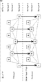
図7の例の場合、主レイヤは、ベースレイヤ(BaseLayer)とエンハンスメントレイヤ(EnhLayer)の2つのレイヤにより構成される。ベースレイヤは、他の主レイヤに依存せず、自身の主レイヤのみで画像が形成されるレイヤである。ベースレイヤのデータは、他の主レイヤを参照せずに符号化・復号される。エンハンスメントレイヤは、ベースレイヤのデータと合成されることにより画像が得られる主レイヤである。エンハンスメントレイヤのデータは、対応するベースレイヤとの間の予測処理(主レイヤ間の予測処理(レイヤ間予測とも称する))が利用可能である。 In the case of the example of FIG. 7, the main layer is composed of two layers, a base layer (BaseLayer) and an enhancement layer (EnhLayer). The base layer is a layer in which an image is formed only by its own main layer without depending on other main layers. The base layer data is encoded / decoded without referring to other main layers. The enhancement layer is a main layer from which an image is obtained by being synthesized with the data of the base layer. The enhancement layer data can be used for prediction processing with a corresponding base layer (prediction processing between main layers (also referred to as inter-layer prediction)).
スケーラブル符号化により階層化された符号化データの主レイヤ数は任意である。以下においては、各主レイヤがベースレイヤか若しくはエンハンスメントレイヤに設定され、各エンハンスメントレイヤには、いずれかのベースレイヤが参照先として設定されるものとする。 The number of main layers of encoded data hierarchized by scalable encoding is arbitrary. In the following, it is assumed that each main layer is a base layer or an enhancement layer, and one of the base layers is set as a reference destination for each enhancement layer.
また、図7の例の場合、ベースレイヤおよびエンハンスメントレイヤは、それぞれ、サブレイヤ0(Sublayer0)、サブレイヤ1(Sublayer1)、サブレイヤ2(Sublayer2)の3つのサブレイヤにより構成されるGOP構造を有する。図7に示される四角は、ピクチャを示しており、その中の文字は、そのピクチャのタイプを示している。例えば、「I」と記載された四角は、Iピクチャを示し、「B」と記載された四角は、Bピクチャを示す。また、各四角間の点線は、依存関係(参照関係)を示す。個の点線で示されるように、上位のサブレイヤのピクチャは、下位のサブレイヤのピクチャに依存する。つまり、サブレイヤ2(Sublayer2)のピクチャは、サブレイヤ1のピクチャやサブレイヤ0のピクチャを参照する。また、サブレイヤ1のピクチャは、サブレイヤ0のピクチャを参照する。サブレイヤ0のピクチャは、サブレイヤ0のピクチャを適宜参照する。
In the case of the example in FIG. 7, the base layer and the enhancement layer each have a GOP structure constituted by three sublayers of sublayer 0 (Sublayer0), sublayer 1 (Sublayer1), and sublayer 2 (Sublayer2). A square shown in FIG. 7 indicates a picture, and characters in the square indicate the type of the picture. For example, a square described as “I” indicates an I picture, and a square described as “B” indicates a B picture. Moreover, the dotted line between each square shows a dependence relationship (reference relationship). As indicated by the dotted lines, the picture of the upper sublayer depends on the picture of the lower sublayer. That is, the picture of sublayer 2 (Sublayer2) refers to the picture of
なお、サブレイヤの階層数(サブレイヤ数)は任意である。また、GOP構造も任意であり、図7の例に限定されない。 The number of sublayers (the number of sublayers) is arbitrary. Further, the GOP structure is also arbitrary and is not limited to the example of FIG.
<サブレイヤを用いたレイヤ間予測の制御>
このような構造の画像データに対して、レイヤ間予測の制御を、サブレイヤを用いて行うようにする。つまり、各ピクチャにおいて複数主レイヤ間の予測を行うか否かを、サブレイヤによって制御するレイヤ間予測制御情報を生成し、伝送するようにする。そして、符号化側においては、符号化の際に、このレイヤ間予測制御情報において指定されるサブレイヤのみレイヤ間予測を利用するようにする。復号側においては、復号の際に、このレイヤ間予測制御情報において指定されるサブレイヤのみレイヤ間予測を利用するようにする。
<Control of inter-layer prediction using sublayers>
Inter-layer prediction is controlled using sub-layers for image data having such a structure. That is, inter-layer prediction control information for controlling whether or not to perform prediction between a plurality of main layers in each picture is generated and transmitted. On the encoding side, during encoding, inter-layer prediction is used only for the sublayers specified in the inter-layer prediction control information. On the decoding side, inter-layer prediction is used only for the sublayers specified in the inter-layer prediction control information at the time of decoding.
つまり、レイヤ間予測制御情報により指定されるサブレイヤに属するピクチャのみがレイヤ間予測を行うことができる。つまり、サブレイヤを指定するだけで、主レイヤ内の全てのピクチャに対するレイヤ間予測の制御を行うことができる。したがって、各ピクチャを個別に制御する必要がなく、主レイヤ毎に制御すれば良いので、その制御に必要な情報量を大幅に低減させることができる。したがって、レイヤ間予測制御による符号化効率の低減を抑制することができる。 That is, only pictures belonging to the sublayer specified by the inter-layer prediction control information can perform inter-layer prediction. That is, it is possible to control inter-layer prediction for all the pictures in the main layer simply by specifying the sublayer. Therefore, it is not necessary to control each picture individually, and it is only necessary to control each main layer, so that the amount of information necessary for the control can be greatly reduced. Therefore, it is possible to suppress a reduction in encoding efficiency due to inter-layer prediction control.
このレイヤ間予測制御情報として、レイヤ間予測を許可するサブレイヤを指定する情報を用いても良いが、レイヤ間予測を許可する最上位サブレイヤを指定する情報を用いても良い。 As this inter-layer prediction control information, information specifying a sub-layer for which inter-layer prediction is permitted may be used, but information for specifying a highest sub-layer for which inter-layer prediction is permitted may be used.
例えば、図7の例に示されるように、上位のサブレイヤ2のピクチャでは、当該ピクチャと参照ピクチャの時間軸上の距離が近い。そのため、インター予測処理による効率が高く、レイヤ間予測による符号化効率の向上は大きくはない。
For example, as shown in the example of FIG. 7, in the
これに対して、例えばサブレイヤ1やサブレイヤ0におけるピクチャでは、当該ピクチャと参照ピクチャの時間軸上の距離が遠く、単一階層による符号化処理では、イントラ予測が行われるCUがより多く選択される。つまり、階層間での予測による符号化効率の向上は大きい。
On the other hand, for example, in the pictures in
つまり、下位のサブレイヤほど、レイヤ間予測を適用することにより符号化効率をより向上させることができる。そのため、レイヤ間予測を一部のサブレイヤで行う場合、最下位から所定の下位層までのサブレイヤにおいてレイヤ間予測を行うように制御するのが望ましい。 That is, encoding efficiency can be improved by applying inter-layer prediction to lower sublayers. Therefore, when inter-layer prediction is performed in some sub-layers, it is desirable to perform control so that inter-layer prediction is performed in sub-layers from the lowest layer to a predetermined lower layer.
その場合、レイヤ間予測をどのサブレイヤまで許可するかを指定すれば良い。このようにすることにより、1サブレイヤを指定するのみでよいので、レイヤ間予測制御情報の情報量はさらに低減させることができる。 In that case, it is only necessary to specify up to which sublayers inter-layer prediction is permitted. By doing so, it is only necessary to designate one sublayer, so that the information amount of inter-layer prediction control information can be further reduced.
<ビデオパラメータセット>
ところで、HEVCにおいては、シーケンスパラメータセット(SPS(Sequence Parameter Set))、ピクチャパラメータセット(PPS)に加え、ビデオパラメータセット(VPS(Video Parameter Set))が規定されている。
<Video parameter set>
By the way, in HEVC, in addition to a sequence parameter set (SPS (Sequence Parameter Set)) and a picture parameter set (PPS), a video parameter set (VPS (Video Parameter Set)) is defined.
ビデオパラメータセット(VPS)は、スケーラブル符号化された符号化データ全体に対して生成される。このビデオパラメータセット(VPS)には、全ての主レイヤに関する情報が格納される。 A video parameter set (VPS) is generated for the entire encoded data that is scalable encoded. This video parameter set (VPS) stores information on all main layers.
シーケンスパラメータセット(SPS)は、主レイヤ毎に生成される。このシーケンスパラメータセット(SPS)には、当該主レイヤに関する情報が格納される。 A sequence parameter set (SPS) is generated for each main layer. In this sequence parameter set (SPS), information on the main layer is stored.
ピクチャパラメータセット(PPS)は、各主レイヤのピクチャ毎に生成される。このピクチャパラメータセットには、当該主レイヤの当該ピクチャに関する情報が格納される。 A picture parameter set (PPS) is generated for each picture of each main layer. In this picture parameter set, information related to the picture of the main layer is stored.
このようなレイヤ間予測制御情報は、例えばシーケンスパラメータセット(SPS)等において、主レイヤ毎に伝送するようにしても良いが、全主レイヤの共通情報として、ビデオパラメータセット(VPS)等において伝送するようにしてもよい。 Such inter-layer prediction control information may be transmitted for each main layer in a sequence parameter set (SPS), for example, but is transmitted in a video parameter set (VPS) or the like as common information for all main layers. You may make it do.
図8にビデオパラメータセットのシンタクスの例を示す。パラメータmax_layer_minus1は、スケーラブル符号化がいくつの階層により行われるか(すなわち主レイヤ数)の最大数を示す。パラメータvps_max_sub_layer_minus1は、スケーラブル符号化の各主レイヤに含まれるサブレイヤの最大数(最大サブレイヤ数)を示す。 FIG. 8 shows an example of the syntax of the video parameter set. The parameter max_layer_minus1 indicates the maximum number of layers in which scalable coding is performed (that is, the number of main layers). The parameter vps_max_sub_layer_minus1 indicates the maximum number of sublayers (maximum number of sublayers) included in each main layer of scalable coding.
パラメータmax_sub_layer_for_inter_layer_prediction[i]は、レイヤ間予測を行うサブレイヤを示す。パラメータmax_sub_layer_for_inter_layer_prediction[i]は、レイヤ間予測を行うサブレイヤの最上位サブレイヤを示す。つまり、最下位サブレイヤからパラメータmax_sub_layer_for_inter_layer_prediction[i]に指定されるサブレイヤまでのサブレイヤにおいてレイヤ間予測が行なわれる。 The parameter max_sub_layer_for_inter_layer_prediction [i] indicates a sublayer for performing inter-layer prediction. The parameter max_sub_layer_for_inter_layer_prediction [i] indicates the highest sublayer of the sublayer that performs inter-layer prediction. That is, inter-layer prediction is performed in sublayers from the lowest sublayer to the sublayer specified by the parameter max_sub_layer_for_inter_layer_prediction [i].
このパラメータmax_sub_layer_for_inter_layer_prediction[i]は、主レイヤ(i)毎に設定される。つまり、パラメータmax_sub_layer_for_inter_layer_prediction[i]は、パラメータmax_layer_minus1以下の主レイヤのそれぞれについて設定される。また、パラメータmax_sub_layer_for_inter_layer_prediction[i]の値は、パラメータvps_max_sub_layer_minus1以下の値に設定される。 This parameter max_sub_layer_for_inter_layer_prediction [i] is set for each main layer (i). That is, the parameter max_sub_layer_for_inter_layer_prediction [i] is set for each of the main layers below the parameter max_layer_minus1. Further, the value of the parameter max_sub_layer_for_inter_layer_prediction [i] is set to a value equal to or smaller than the parameter vps_max_sub_layer_minus1.
なお、レイヤ間予測は、任意のパラメータについて行うことができる。例えば、AVCスケーラブル符号化においては、階層間予測を行うものとして、動きベクトル情報、モード情報、復号画素値、予測残差信号などがある。また、HEVCにおいては、これに加え、直交変換スキップ(Transform Skip)に関するフラグ(flag)、参照ピクチャ、量子化パラメータ、スケーリングリスト(Scaling List)、適応オフセットなどがある。また、レイヤ間予測が行なわれるパラメータの数も任意であり、1つであってもよいし、複数であってもよい。 Note that inter-layer prediction can be performed for arbitrary parameters. For example, in AVC scalable coding, motion vector information, mode information, decoded pixel values, prediction residual signals, and the like are used for performing inter-layer prediction. In addition, in HEVC, there are a flag related to orthogonal transform skip (Transform Skip), a reference picture, a quantization parameter, a scaling list, and an adaptive offset. Also, the number of parameters for which inter-layer prediction is performed is arbitrary, and may be one or plural.
ただし、説明の便宜上、以下においては、レイヤ間予測の一例として、レイヤ間の動き予測(動きベクトル情報の生成)を行う場合について説明する。 However, for convenience of explanation, a case where motion prediction between layers (generation of motion vector information) will be described below as an example of inter-layer prediction.
次に、以上のような本技術について、具体的な装置への適用例について説明する。 Next, an application example of the present technology as described above to a specific apparatus will be described.
<1.第1の実施の形態>
<スケーラブル符号化装置>
図9は、スケーラブル符号化装置の主な構成例を示すブロック図である。
<1. First Embodiment>
<Scalable coding device>
FIG. 9 is a block diagram illustrating a main configuration example of a scalable encoding device.
図9に示されるスケーラブル符号化装置100は、ベースレイヤとエンハンスメントレイヤに階層化された画像データの各レイヤを符号化する。この階層化の基準として用いるパラメータは任意である。スケーラブル符号化装置100は、共通情報生成部101、符号化制御部102、ベースレイヤ画像符号化部103、レイヤ間予測制御部104、およびエンハンスメントレイヤ画像符号化部105を有する。
The
共通情報生成部101は、例えばNALユニットに格納するような画像データの符号化に関する情報を取得する。また、共通情報生成部101は、必要に応じて、ベースレイヤ画像符号化部103、レイヤ間予測制御部104、およびエンハンスメントレイヤ画像符号化部105などから必要な情報を取得する。共通情報生成部101は、それらの情報を基に全主レイヤに関する情報である共通情報を生成する。共通情報には、例えば、ビデオパラメータセット等が含まれる。共通情報生成部101は、生成した共通情報を、例えばNALユニットとして、スケーラブル符号化装置100の外部に出力する。なお、共通情報生成部101は、生成した共通情報を、符号化制御部102にも供給する。さらに、共通情報生成部101は、必要に応じて、生成した共通情報の一部若しくは全部をベースレイヤ画像符号化部103乃至エンハンスメントレイヤ画像符号化部105にも供給する。例えば、共通情報生成部101は、処理対象であるカレント主レイヤのレイヤ間予測実行最大サブレイヤ(max_sub_layer_for_inter_layer_prediction[i])をレイヤ間予測制御部104に供給する。
The common
符号化制御部102は、共通情報生成部101から供給される共通情報に基づいて、ベースレイヤ画像符号化部103乃至エンハンスメントレイヤ画像符号化部105を制御することにより、各主レイヤの符号化を制御する。
The
ベースレイヤ画像符号化部103は、ベースレイヤの画像情報(ベースレイヤ画像情報)を取得する。ベースレイヤ画像符号化部103は、他のレイヤを参照せずに、そのベースレイヤ画像情報を符号化し、ベースレイヤの符号化データ(ベースレイヤ符号化データ)を生成し、出力する。また、ベースレイヤ画像符号化部103は、符号化の際に得られたベースレイヤの符号化に関する情報をレイヤ間予測制御部104に供給する。
The base layer
レイヤ間予測制御部104は、ベースレイヤ画像符号化部103から供給されるベースレイヤの符号化に関する情報を記憶する。また、レイヤ間予測制御部104は、共通情報生成部101から供給されるカレント主レイヤのレイヤ間予測実行最大サブレイヤ(max_sub_layer_for_inter_layer_prediction[i])を取得する。レイヤ間予測制御部104は、その情報に基づいて、記憶しているベースレイヤの符号化に関する情報の、エンハンスメントレイヤ画像符号化部105への供給を制御する。
The inter-layer
エンハンスメントレイヤ画像符号化部105は、エンハンスメントレイヤの画像情報(エンハンスメントレイヤ画像情報)を取得する。エンハンスメントレイヤ画像符号化部105は、そのエンハンスメントレイヤ画像情報を符号化する。その際、エンハンスメントレイヤ画像符号化部105は、レイヤ間予測制御部104の制御に従って、ベースレイヤの符号化に関する情報を参照してレイヤ間予測を行う。より具体的には、例えば、処理対象であるカレントサブレイヤが、レイヤ間予測が許可されたサブレイヤの場合、エンハンスメントレイヤ画像符号化部105は、レイヤ間予測制御部104から供給されるベースレイヤの符号化に関する情報を取得し、それを参照してレイヤ間予測を行い、その予測結果を利用してエンハンスメントレイヤ画像情報を符号化する。また、例えば、カレントサブレイヤが、レイヤ間予測が禁止されたサブレイヤの場合、エンハンスメントレイヤ画像符号化部105は、レイヤ間予測を行わずにエンハンスメントレイヤ画像情報を符号化する。エンハンスメントレイヤ画像符号化部105は、このような符号化により、エンハンスメントレイヤの符号化データ(エンハンスメントレイヤ符号化データ)を生成し、出力する。
The enhancement layer
<ベースレイヤ画像符号化部>
図10は、図9のベースレイヤ画像符号化部103の主な構成例を示すブロック図である。図10に示されるように、ベースレイヤ画像符号化部103は、A/D変換部111、画面並べ替えバッファ112、演算部113、直交変換部114、量子化部115、可逆符号化部116、蓄積バッファ117、逆量子化部118、および逆直交変換部119を有する。また、ベースレイヤ画像符号化部103は、演算部120、ループフィルタ121、フレームメモリ122、選択部123、イントラ予測部124、動き予測・補償部125、予測画像選択部126、およびレート制御部127を有する。
<Base layer image encoding unit>
FIG. 10 is a block diagram illustrating a main configuration example of the base layer
A/D変換部111は、入力された画像データ(ベースレイヤ画像情報)をA/D変換し、変換後の画像データ(デジタルデータ)を、画面並べ替えバッファ112に供給し、記憶させる。画面並べ替えバッファ112は、記憶した表示の順番のフレームの画像を、GOP(Group Of Picture)に応じて、符号化のためのフレームの順番に並べ替え、フレームの順番を並び替えた画像を、演算部113に供給する。また、画面並べ替えバッファ112は、フレームの順番を並び替えた画像を、イントラ予測部124および動き予測・補償部125にも供給する。
The A /
演算部113は、画面並べ替えバッファ112から読み出された画像から、予測画像選択部126を介してイントラ予測部124若しくは動き予測・補償部125から供給される予測画像を減算し、その差分情報を直交変換部114に出力する。例えば、イントラ符号化が行われる画像の場合、演算部113は、画面並べ替えバッファ112から読み出された画像から、イントラ予測部124から供給される予測画像を減算する。また、例えば、インター符号化が行われる画像の場合、演算部113は、画面並べ替えバッファ112から読み出された画像から、動き予測・補償部125から供給される予測画像を減算する。
The
直交変換部114は、演算部113から供給される差分情報に対して、離散コサイン変換やカルーネン・レーベ変換等の直交変換を施す。直交変換部114は、その変換係数を量子化部115に供給する。
The
量子化部115は、直交変換部114から供給される変換係数を量子化する。量子化部115は、レート制御部127から供給される符号量の目標値に関する情報に基づいて量子化パラメータを設定し、その量子化を行う。量子化部115は、量子化された変換係数を可逆符号化部116に供給する。
The
可逆符号化部116は、量子化部115において量子化された変換係数を任意の符号化方式で符号化する。係数データは、レート制御部127の制御の下で量子化されているので、この符号量は、レート制御部127が設定した目標値となる(若しくは目標値に近似する)。
The
また、可逆符号化部116は、イントラ予測のモードを示す情報などをイントラ予測部124から取得し、インター予測のモードを示す情報や差分動きベクトル情報などを動き予測・補償部125から取得する。さらに、可逆符号化部116は、シーケンスパラメータセット(SPS)、およびピクチャパラメータセット(PPS)等を含むベースレイヤのNALユニットを適宜生成する。
Further, the
可逆符号化部116は、これらの各種情報を任意の符号化方式で符号化し、符号化データ(符号化ストリームとも称する)の一部とする(多重化する)。可逆符号化部116は、符号化して得られた符号化データを蓄積バッファ117に供給して蓄積させる。
The
可逆符号化部116の符号化方式としては、例えば、可変長符号化または算術符号化等が挙げられる。可変長符号化としては、例えば、H.264/AVC方式で定められているCAVLC(Context-Adaptive Variable Length Coding)などが挙げられる。算術符号化としては、例えば、CABAC(Context-Adaptive Binary Arithmetic Coding)などが挙げられる。
Examples of the encoding method of the
蓄積バッファ117は、可逆符号化部116から供給された符号化データ(ベースレイヤ符号化データ)を、一時的に保持する。蓄積バッファ117は、所定のタイミングにおいて、保持しているベースレイヤ符号化データを、例えば、後段の図示せぬ記録装置(記録媒体)や伝送路などに出力する。すなわち、蓄積バッファ117は、符号化データを伝送する伝送部でもある。
The
また、量子化部115において量子化された変換係数は、逆量子化部118にも供給される。逆量子化部118は、その量子化された変換係数を、量子化部115による量子化に対応する方法で逆量子化する。逆量子化部118は、得られた変換係数を、逆直交変換部119に供給する。
The transform coefficient quantized by the
逆直交変換部119は、逆量子化部118から供給された変換係数を、直交変換部114による直交変換処理に対応する方法で逆直交変換する。逆直交変換された出力(復元された差分情報)は、演算部120に供給される。
The inverse
演算部120は、逆直交変換部119から供給された逆直交変換結果である、復元された差分情報に、予測画像選択部126を介してイントラ予測部124若しくは動き予測・補償部125からの予測画像を加算し、局部的に復号された画像(復号画像)を得る。その復号画像は、ループフィルタ121またはフレームメモリ122に供給される。
The calculation unit 120 uses the prediction
ループフィルタ121は、デブロックフィルタや適応ループフィルタ等を含み、演算部120から供給される再構成画像に対して適宜フィルタ処理を行う。例えば、ループフィルタ121は、再構成画像に対してデブロックフィルタ処理を行うことにより再構成画像のブロック歪を除去する。また、例えば、ループフィルタ121は、そのデブロックフィルタ処理結果(ブロック歪みの除去が行われた再構成画像)に対して、ウィナーフィルタ(Wiener Filter)を用いてループフィルタ処理を行うことにより画質改善を行う。ループフィルタ121は、フィルタ処理結果(以下、復号画像と称する)をフレームメモリ122に供給する。
The
なお、ループフィルタ121が、再構成画像に対してさらに、他の任意のフィルタ処理を行うようにしてもよい。また、ループフィルタ121は、必要に応じて、フィルタ処理に用いたフィルタ係数等の情報を可逆符号化部116に供給し、それを符号化させるようにすることもできる。
The
フレームメモリ122は、供給される復号画像を記憶し、所定のタイミングにおいて、記憶している復号画像を参照画像として、選択部123に供給する。
The
より具体的には、フレームメモリ122は、演算部120から供給される再構成画像と、ループフィルタ121から供給される復号画像とをそれぞれ記憶する。フレームメモリ122は、所定のタイミングにおいて、若しくは、イントラ予測部124等の外部からの要求に基づいて、記憶している再構成画像を、選択部123を介してイントラ予測部124に供給する。また、フレームメモリ122は、所定のタイミングにおいて、若しくは、動き予測・補償部125等の外部からの要求に基づいて、記憶している復号画像を、選択部123を介して、動き予測・補償部125に供給する。
More specifically, the
選択部123は、フレームメモリ122から供給される参照画像の供給先を選択する。例えば、イントラ予測の場合、選択部123は、フレームメモリ122から供給される参照画像(カレントピクチャ内の画素値)をイントラ予測部124に供給する。また、例えば、インター予測の場合、選択部123は、フレームメモリ122から供給される参照画像を動き予測・補償部125に供給する。
The
イントラ予測部124は、選択部123を介してフレームメモリ122から供給される参照画像であるカレントピクチャ内の画素値を用いて予測画像を生成するイントラ予測(画面内予測)を行う。イントラ予測部124は、予め用意された複数のイントラ予測モードでこのイントラ予測を行う。
The
イントラ予測部124は、候補となる全てのイントラ予測モードで予測画像を生成し、画面並べ替えバッファ112から供給される入力画像を用いて各予測画像のコスト関数値を評価し、最適なモードを選択する。イントラ予測部124は、最適なイントラ予測モードを選択すると、その最適なモードで生成された予測画像を、予測画像選択部126に供給する。
The
また、上述したように、イントラ予測部124は、採用されたイントラ予測モードを示すイントラ予測モード情報等を、適宜可逆符号化部116に供給し、符号化させる。
Further, as described above, the
動き予測・補償部125は、画面並べ替えバッファ112から供給される入力画像と、選択部123を介してフレームメモリ122から供給される参照画像とを用いて動き予測(インター予測)を行う。動き予測・補償部125は、検出された動きベクトルに応じて動き補償処理を行い、予測画像(インター予測画像情報)を生成する。動き予測・補償部125は、予め用意された複数のインター予測モードでこのようなインター予測を行う。
The motion prediction /
動き予測・補償部125は、候補となる全てのインター予測モードで予測画像を生成する。動き予測・補償部125は、画面並べ替えバッファ112から供給される入力画像と、生成した差分動きベクトルの情報などを用いて、各予測画像のコスト関数値を評価し、最適なモードを選択する。動き予測・補償部125は、最適なインター予測モードを選択すると、その最適なモードで生成された予測画像を、予測画像選択部126に供給する。
The motion prediction /
動き予測・補償部125は、採用されたインター予測モードを示す情報や、符号化データを復号する際に、そのインター予測モードで処理を行うために必要な情報等を可逆符号化部116に供給し、符号化させる。必要な情報としては、例えば、生成された差分動きベクトルの情報や、予測動きベクトル情報として、予測動きベクトルのインデックスを示すフラグなどがある。
The motion prediction /
予測画像選択部126は、演算部113や演算部120に供給する予測画像の供給元を選択する。例えば、イントラ符号化の場合、予測画像選択部126は、予測画像の供給元としてイントラ予測部124を選択し、そのイントラ予測部124から供給される予測画像を演算部113や演算部120に供給する。また、例えば、インター符号化の場合、予測画像選択部126は、予測画像の供給元として動き予測・補償部125を選択し、その動き予測・補償部125から供給される予測画像を演算部113や演算部120に供給する。
The predicted
レート制御部127は、蓄積バッファ117に蓄積された符号化データの符号量に基づいて、オーバフローあるいはアンダーフローが発生しないように、量子化部115の量子化動作のレートを制御する。
The
なお、フレームメモリ122は、記憶している復号画像を、ベースレイヤの符号化に関する情報としてレイヤ間予測制御部104に供給する。
The
<エンハンスメントレイヤ画像符号化部>
図11は、図9のエンハンスメントレイヤ画像符号化部105の主な構成例を示すブロック図である。図11に示されるように、エンハンスメントレイヤ画像符号化部105は、図10のベースレイヤ画像符号化部103と基本的に同様の構成を有する。
<Enhancement layer image encoding unit>
FIG. 11 is a block diagram illustrating a main configuration example of the enhancement layer
ただし、エンハンスメントレイヤ画像符号化部105の各部は、ベースレイヤではなく、エンハンスメントレイヤ画像情報の符号化についての処理を行う。つまり、エンハンスメントレイヤ画像符号化部105のA/D変換部111は、エンハンスメントレイヤ画像情報をA/D変換し、エンハンスメントレイヤ画像符号化部105の蓄積バッファ117は、エンハンスメントレイヤ符号化データを、例えば、後段の図示せぬ記録装置(記録媒体)や伝送路などに出力する。
However, each part of the enhancement layer
また、エンハンスメントレイヤ画像符号化部105は、動き予測・補償部125の代わりに、動き予測・補償部135を有する。
Further, the enhancement layer
動き予測・補償部135は、動き予測・補償部125が行うようなピクチャ間の動き予測だけでなく、主レイヤ間の動き予測も行うことができる。動き予測・補償部135は、レイヤ間予測制御部104から供給されるベースレイヤの符号化に関する情報(例えば、ベースレイヤの復号画像)を取得する。動き予測・補償部135は、インター予測の候補モードの1つとして、そのベースレイヤの符号化に関する情報を用いて主レイヤの動き予測を行う。
The motion prediction /
<共通情報生成部とレイヤ間予測制御部>
図12は、図9の共通情報生成部101およびレイヤ間予測制御部104の主な構成例を示すブロック図である。
<Common information generator and inter-layer prediction controller>
12 is a block diagram illustrating a main configuration example of the common
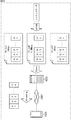
図12に示されるように、共通情報生成部101は、主レイヤ最大数設定部141、サブレイヤ最大数設定部142、レイヤ間予測実行最大サブレイヤ設定部143を有する。また、レイヤ間予測制御部104は、レイヤ間予測実行制御部151および符号化関連情報バッファ152を有する。
As illustrated in FIG. 12, the common
主レイヤ最大数設定部141は、主レイヤの最大数を示す情報(max_layer_minus1)を設定する。サブレイヤ最大数設定部142は、サブレイヤの最大数を示す情報(vps_max_sub_layer_minus1)を設定する。レイヤ間予測実行最大サブレイヤ設定部143は、カレント主レイヤのレイヤ間予測を許可するサブレイヤの最上位サブレイヤを指定する情報(max_sub_layer_for_inter_layer_prediction[i])を設定する。
The main layer maximum
共通情報生成部101は、それらの情報を共通情報(ビデオパラメータセット(VPS))として、スケーラブル符号化装置100の外部に出力する。また、共通情報生成部101は、その共通情報(ビデオパラメータセット(VPS))を符号化制御部102に供給する。さらに、共通情報生成部101は、カレント主レイヤのレイヤ間予測を許可するサブレイヤの最上位サブレイヤを指定する情報(max_sub_layer_for_inter_layer_prediction[i])をレイヤ間予測制御部104に供給する。
The common
レイヤ間予測実行制御部151は、共通情報生成部101から供給される共通情報に基づいて、レイヤ間予測の実行を制御する。より具体的には、レイヤ間予測実行制御部151は、共通情報生成部101から供給される、レイヤ間予測を許可するサブレイヤの最上位サブレイヤを指定する情報(max_sub_layer_for_inter_layer_prediction[i])に基づいて、符号化関連情報バッファ152を制御する。
The inter-layer prediction
符号化関連情報バッファ152は、ベースレイヤ画像符号化部103から供給されるベースレイヤの符号化に関する情報(例えば、ベースレイヤの復号画像)を取得し、記憶する。符号化関連情報バッファ152は、レイヤ間予測実行制御部151の制御に従って、記憶しているベースレイヤの符号化に関する情報をエンハンスメントレイヤ画像符号化部105に供給する。
The encoding
レイヤ間予測実行制御部151は、この符号化関連情報バッファ152からのベースレイヤの符号化に関する情報の供給を制御する。例えば、レイヤ間予測を許可するサブレイヤの最上位サブレイヤを指定する情報(max_sub_layer_for_inter_layer_prediction[i])において、カレントサブレイヤのレイヤ間予測が許可されている場合、レイヤ間予測実行制御部151は、カレントサブレイヤについて、符号化関連情報バッファ152に記憶されているベースレイヤの符号化に関する情報(例えば、ベースレイヤの復号画像)を、エンハンスメントレイヤ画像符号化部105に供給させる。
The inter-layer prediction
また、例えば、レイヤ間予測を許可するサブレイヤの最上位サブレイヤを指定する情報(max_sub_layer_for_inter_layer_prediction[i])において、カレントサブレイヤのレイヤ間予測が許可されていない場合、レイヤ間予測実行制御部151は、カレントサブレイヤについて、符号化関連情報バッファ152に記憶されているベースレイヤの符号化に関する情報(例えば、ベースレイヤの復号画像)を、エンハンスメントレイヤ画像符号化部105に供給させない。
Also, for example, in the information (max_sub_layer_for_inter_layer_prediction [i]) that specifies the highest sublayer of the sublayer that permits inter-layer prediction, when inter-layer prediction of the current sub-layer is not permitted, the inter-layer prediction
以上のように、スケーラブル符号化装置100は、サブレイヤを用いてレイヤ間予測を制御するレイヤ間予測制御情報を伝送するので、レイヤ間予測制御による符号化効率の低減を抑制することができる。これにより、スケーラブル符号化装置100は、符号化・復号による画質の低減を抑制することができる。
As described above,
<符号化処理の流れ>
次に、以上のようなスケーラブル符号化装置100により実行される各処理の流れについて説明する。最初に、図13のフローチャートを参照して、符号化処理の流れの例を説明する。
<Flow of encoding process>
Next, the flow of each process executed by the
符号化処理が開始されると、ステップS101において、スケーラブル符号化装置100の共通情報生成部101は、共通情報を生成する。ステップS102において、符号化制御部102は、最初の主レイヤを処理対象とする。
When the encoding process is started, in step S101, the common
ステップS103において、符号化制御部102は、ステップS101において生成された共通情報に基づいて、処理対象であるカレント主レイヤがベースレイヤであるか否かを判定する。カレント主レイヤがベースレイヤであると判定された場合、処理は、ステップS104に進む。
In step S103, the
ステップS104において、ベースレイヤ画像符号化部103は、ベースレイヤ符号化処理を行う。ステップS104の処理が終了すると、処理は、ステップS108に進む。
In step S104, the base layer
また、ステップS103において、カレント主レイヤがエンハンスメントレイヤであると判定された場合、処理は、ステップS105に進む。ステップS105において、符号化制御部102は、カレント主レイヤに対応する(すなわち、参照先とする)ベースレイヤを決定する。
If it is determined in step S103 that the current main layer is an enhancement layer, the process proceeds to step S105. In step S105, the
ステップS106において、レイヤ間予測制御部104は、レイヤ間予測制御処理を行う。
In step S106, the inter-layer
ステップS107において、エンハンスメントレイヤ画像符号化部105は、エンハンスメントレイヤ符号化処理を行う。ステップS107の処理が終了すると、処理は、ステップS108に進む。
In step S107, the enhancement layer
ステップS108において、符号化制御部102は、全ての主レイヤを処理したか否かを判定する。未処理の主レイヤが存在すると判定された場合、処理は、ステップS109に進む。
In step S108, the
ステップS109において、符号化制御部102は、次の未処理の主レイヤを処理対象(カレント主レイヤ)とする。ステップS109の処理が終了すると、処理は、ステップS103に戻る。ステップS103乃至ステップS109の処理が繰り返し実行され、各主レイヤが符号化される。
In step S109, the
そして、ステップS108において、全ての主レイヤが処理されたと判定された場合、符号化処理が終了する。 If it is determined in step S108 that all main layers have been processed, the encoding process ends.
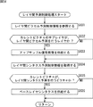
<共通情報生成処理の流れ>
次に、図14のフローチャートを参照して、図13のステップS101において実行される共通情報生成処理の流れの例を説明する。
<Common information generation process flow>
Next, an example of the flow of common information generation processing executed in step S101 of FIG. 13 will be described with reference to the flowchart of FIG.
共通情報生成処理が開始されると、主レイヤ最大数設定部141は、ステップS121において、パラメータ(max_layer_minus1)を設定する。ステップS122において、サブレイヤ最大数設定部142は、パラメータ(vps_max_sub_layers_minus1)を設定する。ステップS123において、レイヤ間予測実行最大サブレイヤ設定部143は、各主レイヤについて、パラメータ(max_sub_layer_for_inter_layer_prediction[i])を設定する。
When the common information generation process is started, the main layer maximum
ステップS124において、共通情報生成部101は、ステップS121乃至ステップS123において設定された各パラメータを含むビデオパラメータセットを共通情報として生成する。
In step S124, the common
ステップS125において、共通情報生成部101は、ステップS124の処理により生成したビデオパラメータセットを、スケーラブル符号化装置100の外部および符号化制御部102に供給する。また、共通情報生成部101は、ステップS123において設定したパラメータ(max_sub_layer_for_inter_layer_prediction[i])をレイヤ間予測制御部104に供給する。
In step S125, the common
ステップS125の処理が終了すると、共通情報生成処理が終了し、処理は、図13に戻る。 When the process of step S125 ends, the common information generation process ends, and the process returns to FIG.
<ベースレイヤ符号化処理の流れ>
次に、図15のフローチャートを参照して、図13のステップS104において実行されるベースレイヤ符号化処理の流れの例を説明する。
<Flow of base layer encoding process>
Next, an example of the flow of the base layer encoding process executed in step S104 of FIG. 13 will be described with reference to the flowchart of FIG.
ステップS141において、ベースレイヤ画像符号化部103のA/D変換部111は入力されたベースレイヤの画像情報(画像データ)をA/D変換する。ステップS142において、画面並べ替えバッファ112は、A/D変換されたベースレイヤの画像情報(デジタルデータ)を記憶し、各ピクチャを、表示する順番から符号化する順番へ並べ替える。
In step S141, the A /
ステップS143において、イントラ予測部124は、イントラ予測モードのイントラ予測処理を行う。ステップS144において、動き予測・補償部125は、インター予測モードでの動き予測や動き補償を行う動き予測・補償処理を行う。ステップS145において、予測画像選択部126は、イントラ予測部124および動き予測・補償部125から出力された各コスト関数値に基づいて、最適なモードを決定する。つまり、予測画像選択部126は、イントラ予測部124により生成された予測画像と、動き予測・補償部125により生成された予測画像のいずれか一方を選択する。ステップS146において、演算部113は、ステップS142の処理により並び替えられた画像と、ステップS145の処理により選択された予測画像との差分を演算する。差分データは元の画像データに較べてデータ量が低減される。したがって、画像をそのまま符号化する場合に較べて、データ量を圧縮することができる。
In step S143, the
ステップS147において、直交変換部114は、ステップS146の処理により生成された差分情報に対する直交変換処理を行う。ステップS148において、量子化部115は、レート制御部127により算出された量子化パラメータを用いて、ステップS147の処理により得られた直交変換係数を量子化する。
In step S147, the
ステップS148の処理により量子化された差分情報は、次のようにして局部的に復号される。すなわち、ステップS149において、逆量子化部118は、ステップS148の処理により生成された量子化された係数(量子化係数とも称する)を、量子化部115の特性に対応する特性で逆量子化する。ステップS150において、逆直交変換部119は、ステップS147の処理により得られた直交変換係数を逆直交変換する。ステップS151において、演算部120は、予測画像を局部的に復号された差分情報に加算し、局部的に復号された画像(演算部113への入力に対応する画像)を生成する。
The difference information quantized by the process of step S148 is locally decoded as follows. That is, in step S149, the inverse quantization unit 118 inversely quantizes the quantized coefficient (also referred to as quantization coefficient) generated by the process in step S148 with characteristics corresponding to the characteristics of the
ステップS152においてループフィルタ121は、ステップS151の処理により生成された画像をフィルタリングする。これによりブロック歪み等が除去される。ステップS153において、フレームメモリ122は、ステップS152の処理によりブロック歪みの除去等が行われた画像を記憶する。なお、フレームメモリ122にはループフィルタ121によりフィルタ処理されていない画像も演算部120から供給され、記憶される。このフレームメモリ122に記憶された画像は、ステップS143の処理やステップS144の処理に利用される。
In step S152, the
また、ステップS154において、フレームメモリ122は、自身に記憶された画像を、ベースレイヤの符号化に関する情報として、レイヤ間予測制御部104に供給し、記憶させる。
In step S154, the
ステップS155において、可逆符号化部116は、ステップS148の処理により量子化された係数を符号化する。すなわち、差分画像に対応するデータに対して、可変長符号化や算術符号化等の可逆符号化が行われる。
In step S155, the
また、このとき、可逆符号化部116は、ステップS145の処理により選択された予測画像の予測モードに関する情報を符号化し、差分画像を符号化して得られる符号化データに付加する。つまり、可逆符号化部116は、イントラ予測部124から供給される最適イントラ予測モード情報、または、動き予測・補償部125から供給される最適インター予測モードに応じた情報なども符号化し、符号化データに付加する。
At this time, the
ステップS156において蓄積バッファ117は、ステップS155の処理により得られたベースレイヤ符号化データを蓄積する。蓄積バッファ117に蓄積されたベースレイヤ符号化データは、適宜読み出され、伝送路や記録媒体を介して復号側に伝送される。
In step S156, the
ステップS157においてレート制御部127は、ステップS156の処理により蓄積バッファ117に蓄積された符号化データの符号量(発生符号量)に基づいて、オーバフローあるいはアンダーフローが発生しないように、量子化部115の量子化動作のレートを制御する。また、レート制御部127は、量子化パラメータに関する情報を、量子化部115に供給する。
In step S157, the
ステップS157の処理が終了すると、ベースレイヤ符号化処理が終了し、処理は図13に戻る。ベースレイヤ符号化処理は、例えば、ピクチャ単位で実行される。つまり、カレントレイヤの各ピクチャに対してベースレイヤ符号化処理が実行される。ただし、ベースレイヤ符号化処理内の各処理は、それぞれの処理単位毎に行われる。 When the process of step S157 ends, the base layer encoding process ends, and the process returns to FIG. The base layer encoding process is executed in units of pictures, for example. That is, the base layer encoding process is executed for each picture in the current layer. However, each process in the base layer encoding process is performed for each processing unit.
<レイヤ間予測制御処理の流れ>
次に、図13のステップS106において実行されるレイヤ間予測制御処理の流れの例を、図16のフローチャートを参照して説明する。
<Flow of inter-layer prediction control processing>
Next, an example of the flow of inter-layer prediction control processing executed in step S106 in FIG. 13 will be described with reference to the flowchart in FIG.
レイヤ間予測制御処理が開始されると、レイヤ間予測実行制御部151は、ステップS171において、図14の共通情報生成処理により共通情報生成部101から供給されたパラメータ(max_sub_layer_for_inter_layer_prediction[i])を参照する。
When the inter-layer prediction control process is started, the inter-layer prediction
ステップS172において、レイヤ間予測実行制御部151は、そのパラメータの値に基づいて、カレントピクチャのカレントサブレイヤが、レイヤ間予測を行うレイヤであるか否かを判定する。パラメータ(max_sub_layer_for_inter_layer_prediction[i])により指定されるレイヤが、カレントサブレイヤよりも上位のサブレイヤであり、カレントサブレイヤにおけるレイヤ間予測が許可されていると判定された場合、処理は、ステップS173に進む。
In step S172, the inter-layer prediction
ステップS173において、レイヤ間予測実行制御部151は、符号化関連情報バッファ152を制御し、符号化関連情報バッファ152に記憶されているベースレイヤの符号化に関する情報を、エンハンスメントレイヤ画像符号化部105に供給させる。ステップS173の処理が終了すると、レイヤ間予測制御処理が終了し、処理は、図13に戻る。
In step S173, the inter-layer prediction
また、ステップS172において、カレントサブレイヤにおけるレイヤ間予測が許可されていないと判定された場合、ベースレイヤの符号化に関する情報の供給は行われずに、レイヤ間予測制御処理が終了し、処理は図13に戻る。つまり、このカレントサブレイヤに対する符号化においては、レイヤ間予測は行われない。 If it is determined in step S172 that inter-layer prediction in the current sublayer is not permitted, the information related to base layer encoding is not supplied, and the inter-layer prediction control process is terminated. Return to. That is, inter-layer prediction is not performed in the encoding for the current sublayer.
<エンハンスメントレイヤ符号化処理の流れ>
次に、図17のフローチャートを参照して、図13のステップS107において実行されるエンハンスメントレイヤ符号化処理の流れの例を説明する。
<Enhancement layer coding process flow>
Next, an example of the flow of the enhancement layer encoding process executed in step S107 of FIG. 13 will be described with reference to the flowchart of FIG.
エンハンスメントレイヤ符号化処理のステップS191乃至ステップS193、並びに、ステップS195乃至ステップS206の各処理は、ベースレイヤ符号化処理のステップS141乃至ステップS143、ステップS145乃至ステップS153、並びに、ステップS155乃至ステップS157の各処理と同様に実行される。ただし、エンハンスメントレイヤ符号化処理の各処理は、エンハンスメントレイヤ画像符号化部105の各処理部により、エンハンスメントレイヤ画像情報に対して行われる。
Steps S191 to S193 of the enhancement layer encoding process and steps S195 to S206 are the same as steps S141 to S143, step S145 to S153, and steps S155 to S157 of the base layer encoding process. It is executed in the same manner as each process. However, each process of the enhancement layer encoding process is performed on the enhancement layer image information by each processing unit of the enhancement layer
なお、ステップS194において、動き予測・補償部135は、エンハンスメントレイヤ画像情報に対して、動き予測・補償処理を行う。
In step S194, the motion prediction /
ステップS206の処理が終了すると、エンハンスメントレイヤ符号化処理が終了され、処理は図13に戻る。エンハンスメントレイヤ符号化処理は、例えば、ピクチャ単位で実行される。つまり、カレントレイヤの各ピクチャに対してエンハンスメントレイヤ符号化処理が実行される。ただし、エンハンスメントレイヤ符号化処理内の各処理は、それぞれの処理単位毎に行われる。 When the process of step S206 ends, the enhancement layer encoding process ends, and the process returns to FIG. The enhancement layer encoding process is executed in units of pictures, for example. That is, the enhancement layer encoding process is executed for each picture in the current layer. However, each process in the enhancement layer encoding process is performed for each processing unit.
<動き予測・補償処理の流れ>
次に、図18のフローチャートを参照して、図17のステップS194において実行される動き予測・補償処理の流れの例を説明する。
<Flow of motion prediction / compensation processing>
Next, an example of the flow of the motion prediction / compensation process executed in step S194 in FIG. 17 will be described with reference to the flowchart in FIG.
動き予測・補償処理が開始されると、動き予測・補償部135は、ステップS221において、カレント主レイヤ内で動き予測を行う。
When the motion prediction / compensation process is started, the motion prediction /
ステップS222において、動き予測・補償部135は、カレントピクチャについて、レイヤ間予測を行うか否かを判定する。レイヤ間予測制御部104からベースレイヤの符号化に関する情報が供給され、レイヤ間予測を行うと判定された場合、処理は、ステップS223に進む。
In step S222, the motion prediction /
ステップS223において、動き予測・補償部135は、レイヤ間予測制御部104から供給されるベースレイヤの符号化に関する情報を取得する。ステップS224において、動き予測・補償部135は、ステップS223において取得した情報を用いてレイヤ間予測を行う。ステップS224の処理が終了すると、処理は、ステップS225に進む。
In step S <b> 223, the motion prediction /
また、ステップS222において、レイヤ間予測制御部104からベースレイヤの符号化に関する情報が供給されておらず、レイヤ間予測を行わないと判定された場合、カレントピクチャについてレイヤ間予測が省略され、処理は、ステップS225に進む。
Also, in step S222, when information related to base layer encoding is not supplied from the inter-layer
ステップS225において、動き予測・補償部135は、各予測モードについてコスト関数値を算出する。ステップS226において、動き予測・補償部135は、そのコスト関数値に基づいて最適なインター予測モードを選択する。
In step S225, the motion prediction /
ステップS227において、動き予測・補償部135は、ステップS226において選択された最適なインター予測モードで動き補償を行い、予測画像を生成する。ステップS228において、動き予測・補償部135は、その最適なインター予測モードについて、インター予測に関する情報を生成する。
In step S227, the motion prediction /
ステップS228の処理が終了すると、動き予測・補償処理が終了し、処理は、図17に戻る。以上のように、レイヤ間予測を適宜用いた、動き予測・補償処理が行われる。この処理は、例えば、ブロック単位で実行される。ただし、動き予測・補償処理内の各処理は、それぞれの処理単位毎に行われる。 When the process of step S228 ends, the motion prediction / compensation process ends, and the process returns to FIG. As described above, motion prediction / compensation processing using inter-layer prediction as appropriate is performed. This process is executed in units of blocks, for example. However, each process in the motion prediction / compensation process is performed for each processing unit.
以上のように各処理を実行することにより、スケーラブル符号化装置100は、符号化効率の低減を抑制し、符号化・復号による画質の低減を抑制することができる。
By executing each processing as described above, the
<2.第2の実施の形態>
<スケーラブル復号装置>
次に、以上のようにスケーラブル符号化(階層符号化)された符号化データ(ビットストリーム)の復号について説明する。図19は、図9のスケーラブル符号化装置100に対応するスケーラブル復号装置の主な構成例を示すブロック図である。図19に示されるスケーラブル復号装置200は、例えばスケーラブル符号化装置100により画像データがスケーラブル符号化されて得られた符号化データを、その符号化方法に対応する方法でスケーラブル復号する。
<2. Second Embodiment>
<Scalable decoding device>
Next, decoding of encoded data (bit stream) that has been scalable encoded (hierarchical encoded) as described above will be described. FIG. 19 is a block diagram illustrating a main configuration example of a scalable decoding device corresponding to the
図19に示されるように、スケーラブル復号装置200は、共通情報取得部201、復号制御部202、ベースレイヤ画像復号部203、レイヤ間予測制御部204、およびエンハンスメントレイヤ画像復号部205を有する。
As illustrated in FIG. 19, the
共通情報取得部201は、符号化側から伝送される共通情報(例えば、ビデオパラメータセット(VPS))を取得する。共通情報取得部201は、取得した共通情報より復号に関する情報を抽出し、それを復号制御部202に供給する。また、共通情報取得部201は、共通情報の一部若しくは全部を、ベースレイヤ画像復号部203乃至エンハンスメントレイヤ画像復号部205に適宜供給する。
The common
復号制御部202は、共通情報取得部201から供給された復号に関する情報を取得し、その情報に基づいて、ベースレイヤ画像復号部203乃至エンハンスメントレイヤ画像復号部205を制御することにより、各主レイヤの復号を制御する。
The
ベースレイヤ画像復号部203は、ベースレイヤ画像符号化部103に対応する画像復号部であり、例えばベースレイヤ画像符号化部103によりベースレイヤ画像情報が符号化されて得られたベースレイヤ符号化データを取得する。ベースレイヤ画像復号部203は、他のレイヤを参照せずに、そのベースレイヤ符号化データを復号し、ベースレイヤ画像情報を再構築し、出力する。また、ベースレイヤ画像復号部203は、その復号により得られたベースレイヤの復号に関する情報をレイヤ間予測制御部204に供給する。
The base layer
レイヤ間予測制御部204は、エンハンスメントレイヤ画像復号部205によるレイヤ間予測の実行を制御する。レイヤ間予測制御部204は、ベースレイヤ画像復号部203から供給されるベースレイヤの復号に関する情報を取得し、記憶する。また、レイヤ間予測制御部204は、レイヤ間予測が許可されるサブレイヤの復号において、記憶しているベースレイヤの復号に関する情報を、エンハンスメントレイヤ画像復号部205に供給する。
The inter-layer
エンハンスメントレイヤ画像復号部205は、エンハンスメントレイヤ画像符号化部105に対応する画像復号部であり、例えばエンハンスメントレイヤ画像符号化部105によりエンハンスメントレイヤ画像情報が符号化されて得られたエンハンスメントレイヤ符号化データを取得する。エンハンスメントレイヤ画像復号部205は、そのエンハンスメントレイヤ符号化データを復号する。その際、エンハンスメントレイヤ画像復号部205は、レイヤ間予測制御部204の制御に従って、ベースレイヤの復号に関する情報を参照してレイヤ間予測を行う。より具体的には、例えば、処理対象であるカレントサブレイヤが、レイヤ間予測が許可されたサブレイヤの場合、エンハンスメントレイヤ画像復号部205は、レイヤ間予測制御部204から供給されるベースレイヤの復号に関する情報を取得し、それを参照してレイヤ間予測を行い、その予測結果を利用してエンハンスメントレイヤ符号化データを復号する。また、例えば、カレントサブレイヤが、レイヤ間予測が禁止されたサブレイヤの場合、エンハンスメントレイヤ画像復号部205は、レイヤ間予測を行わずにエンハンスメントレイヤ符号化データを復号する。エンハンスメントレイヤ画像復号部205は、このような符号化により、エンハンスメントレイヤ画像情報を再構築し、出力する。
The enhancement layer
<ベースレイヤ画像復号部>
図20は、図19のベースレイヤ画像復号部203の主な構成例を示すブロック図である。図20に示されるようにベースレイヤ画像復号部203は、蓄積バッファ211、可逆復号部212、逆量子化部213、逆直交変換部214、演算部215、ループフィルタ216、画面並べ替えバッファ217、およびD/A変換部218を有する。また、ベースレイヤ画像復号部203は、フレームメモリ219、選択部220、イントラ予測部221、動き補償部222、および選択部223を有する。
<Base layer image decoding unit>
FIG. 20 is a block diagram illustrating a main configuration example of the base layer
蓄積バッファ211は、伝送されてきたベースレイヤ符号化データを受け取る受け取り部でもある。蓄積バッファ211は、伝送されてきたベースレイヤ符号化データを受け取って、蓄積し、所定のタイミングにおいてその符号化データを可逆復号部212に供給する。このベースレイヤ符号化データには、予測モード情報などの復号に必要な情報が付加されている。
The
可逆復号部212は、蓄積バッファ211より供給された、可逆符号化部116により符号化された情報を、可逆符号化部116の符号化方式に対応する方式で復号する。可逆復号部212は、復号して得られた差分画像の量子化された係数データを、逆量子化部213に供給する。
The
また、可逆復号部212は、ベースレイヤ符号化データに含まれるビデオパラメータセット(VPS)、シーケンスパラメータセット(SPS)、およびピクチャパラメータセット(PPS)等を含むNALユニットを適宜抽出し、取得する。可逆復号部212は、それらの情報から、最適な予測モードに関する情報を抽出し、その情報に基づいて最適な予測モードにイントラ予測モードが選択されたかインター予測モードが選択されたかを判定し、その最適な予測モードに関する情報を、イントラ予測部221および動き補償部222の内、選択されたと判定したモードの方に供給する。つまり、例えば、ベースレイヤ画像符号化部103において最適な予測モードとしてイントラ予測モードが選択された場合、その最適な予測モードに関する情報がイントラ予測部221に供給される。また、例えば、ベースレイヤ画像符号化部103において最適な予測モードとしてインター予測モードが選択された場合、その最適な予測モードに関する情報が動き補償部222に供給される。
In addition, the
さらに、可逆復号部212は、例えば、量子化行列や量子化パラメータ等の、逆量子化に必要な情報をNALユニット等から抽出し、それを逆量子化部213に供給する。
Further, the
逆量子化部213は、可逆復号部212により復号されて得られた量子化された係数データを、量子化部115の量子化方式に対応する方式で逆量子化する。なお、この逆量子化部213は、逆量子化部118と同様の処理部である。つまり、逆量子化部213の説明は、逆量子化部118にも準用することができる。ただし、データの入出力先等は、装置に応じて適宜、変えて読む必要がある。逆量子化部213は、得られた係数データを逆直交変換部214に供給する。
The
逆直交変換部214は、逆量子化部213から供給される係数データを、直交変換部114の直交変換方式に対応する方式で逆直交変換する。なお、この逆直交変換部214は、逆直交変換部119と同様の処理部である。つまり、逆直交変換部214の説明は、逆直交変換部119にも準用することができる。ただし、データの入出力先等は、装置に応じて適宜、変えて読む必要がある。
The inverse
逆直交変換部214は、この逆直交変換処理により、直交変換部114において直交変換される前の残差データに対応する復号残差データを得る。逆直交変換されて得られた復号残差データは、演算部215に供給される。また、演算部215には、選択部223を介して、イントラ予測部221若しくは動き補償部222から予測画像が供給される。
The inverse
演算部215は、その復号残差データと予測画像とを加算し、演算部113により予測画像が減算される前の画像データに対応する復号画像データを得る。演算部215は、その復号画像データをループフィルタ216に供給する。
The
ループフィルタ216は、供給された復号画像に対して、デブロックフィルタや適応ループフィルタ等を含むフィルタ処理を適宜施し、それを画面並べ替えバッファ217およびフレームメモリ219に供給する。例えば、ループフィルタ216は、復号画像に対してデブロックフィルタ処理を行うことにより復号画像のブロック歪を除去する。また、例えば、ループフィルタ216は、そのデブロックフィルタ処理結果(ブロック歪みの除去が行われた復号画像)に対して、ウィナーフィルタ(Wiener Filter)を用いてループフィルタ処理を行うことにより画質改善を行う。なお、このループフィルタ216は、ループフィルタ121と同様の処理部である。
The
なお、演算部215から出力される復号画像は、ループフィルタ216を介さずに画面並べ替えバッファ217やフレームメモリ219に供給することができる。つまり、ループフィルタ216によるフィルタ処理の一部若しくは全部は省略することができる。
Note that the decoded image output from the
画面並べ替えバッファ217は、復号画像の並べ替えを行う。すなわち、画面並べ替えバッファ112により符号化の順番のために並べ替えられたフレームの順番が、元の表示の順番に並べ替えられる。D/A変換部218は、画面並べ替えバッファ217から供給された画像をD/A変換し、図示せぬディスプレイに出力し、表示させる。
The
フレームメモリ219は、供給される復号画像を記憶し、所定のタイミングにおいて、若しくは、イントラ予測部221や動き補償部222等の外部の要求に基づいて、記憶している復号画像を参照画像として、選択部220に供給する。
The
また、フレームメモリ219は、記憶する復号画像を、ベースレイヤの復号に関する情報として、レイヤ間予測制御部204に供給する。
Also, the
選択部220は、フレームメモリ219から供給される参照画像の供給先を選択する。選択部220は、イントラ符号化された画像を復号する場合、フレームメモリ219から供給される参照画像をイントラ予測部221に供給する。また、選択部220は、インター符号化された画像を復号する場合、フレームメモリ219から供給される参照画像を動き補償部222に供給する。
The
イントラ予測部221には、ヘッダ情報を復号して得られたイントラ予測モードを示す情報等が可逆復号部212から適宜供給される。イントラ予測部221は、イントラ予測部124において用いられたイントラ予測モードで、フレームメモリ219から取得した参照画像を用いてイントラ予測を行い、予測画像を生成する。イントラ予測部221は、生成した予測画像を選択部223に供給する。
Information indicating the intra prediction mode obtained by decoding the header information is appropriately supplied from the
動き補償部222は、ヘッダ情報を復号して得られた情報(最適予測モード情報、参照画像情報等)を可逆復号部212から取得する。
The
動き補償部222は、可逆復号部212から取得された最適予測モード情報が示すインター予測モードで、フレームメモリ219から取得した参照画像を用いて動き補償を行い、予測画像を生成する。
The
選択部223は、イントラ予測部221からの予測画像または動き補償部222からの予測画像を、演算部215に供給する。そして、演算部215においては、動きベクトルが用いられて生成された予測画像と逆直交変換部214からの復号残差データ(差分画像情報)とが加算されて元の画像が復号される。
The
<エンハンスメントレイヤ画像符号化部>
図21は、図19のエンハンスメントレイヤ画像復号部205の主な構成例を示すブロック図である。図21に示されるように、エンハンスメントレイヤ画像復号部205は、図20のベースレイヤ画像復号部203と基本的に同様の構成を有する。
<Enhancement layer image encoding unit>
FIG. 21 is a block diagram illustrating a main configuration example of the enhancement layer
ただし、エンハンスメントレイヤ画像復号部205の各部は、ベースレイヤではなく、エンハンスメントレイヤ符号化データの復号についての処理を行う。つまり、エンハンスメントレイヤ画像復号部205の蓄積バッファ211は、エンハンスメントレイヤ符号化データを記憶し、エンハンスメントレイヤ画像復号部205のD/A変換部218は、エンハンスメントレイヤ画像情報を、例えば、後段の図示せぬ記録装置(記録媒体)や伝送路などに出力する。
However, each unit of the enhancement layer
また、エンハンスメントレイヤ画像復号部205は、動き補償部222の代わりに、動き補償部232を有する。
Further, the enhancement layer
動き補償部232は、動き補償部222が行うようなピクチャ間の動き補償だけでなく、主レイヤ間の動き補償も行うことができる。その場合、動き補償部232は、レイヤ間予測制御部204から供給されるベースレイヤの復号に関する情報(例えば、ベースレイヤの復号画像)を取得する。動き補償部232は、そのベースレイヤの復号に関する情報を用いて主レイヤの動き補償を行う。
The
<共通情報取得部とレイヤ間予測制御部>
図22は、図19の共通情報取得部201およびレイヤ間予測制御部204の主な構成例を示すブロック図である。
<Common information acquisition unit and inter-layer prediction control unit>
FIG. 22 is a block diagram illustrating a main configuration example of the common
図22に示されるように、共通情報取得部201は、主レイヤ最大数取得部241、サブレイヤ最大数取得部242、レイヤ間予測実行最大サブレイヤ取得部243を有する。また、レイヤ間予測制御部204は、レイヤ間予測実行制御部251および復号関連情報バッファ252を有する。
As illustrated in FIG. 22, the common
主レイヤ最大数取得部241は、符号化側から伝送された共通情報に含まれる主レイヤの最大数を示す情報(max_layer_minus1)を取得する。サブレイヤ最大数取得部242は、符号化側から伝送された共通情報に含まれるサブレイヤの最大数を示す情報(vps_max_sub_layer_minus1)を取得する。レイヤ間予測実行最大サブレイヤ取得部243は、符号化側から伝送された共通情報に含まれるカレント主レイヤのレイヤ間予測を許可するサブレイヤの最上位サブレイヤを指定する情報(max_sub_layer_for_inter_layer_prediction[i])を取得する。
The main layer maximum
共通情報取得部201は、取得した共通情報に含まれる復号に関する情報(例えばビデオパラメータセット(VPS)など)を復号制御部202に供給する。さらに、共通情報取得部201は、カレント主レイヤのレイヤ間予測を許可するサブレイヤの最上位サブレイヤを指定する情報(max_sub_layer_for_inter_layer_prediction[i])をレイヤ間予測制御部204に供給する。
The common
レイヤ間予測実行制御部251は、共通情報取得部201から供給される共通情報に基づいて、レイヤ間予測の実行を制御する。より具体的には、レイヤ間予測実行制御部251は、共通情報取得部201から供給される、レイヤ間予測を許可するサブレイヤの最上位サブレイヤを指定する情報(max_sub_layer_for_inter_layer_prediction[i])に基づいて、復号関連情報バッファ252を制御する。
The inter-layer prediction
復号関連情報バッファ252は、ベースレイヤ画像復号部203から供給されるベースレイヤの復号に関する情報(例えば、ベースレイヤの復号画像)を取得し、記憶する。復号関連情報バッファ252は、レイヤ間予測実行制御部251の制御に従って、記憶しているベースレイヤの符号化に関する情報をエンハンスメントレイヤ画像復号部205に供給する。
The decoding related
レイヤ間予測実行制御部251は、この復号関連情報バッファ252からのベースレイヤの復号に関する情報の供給を制御する。例えば、レイヤ間予測を許可するサブレイヤの最上位サブレイヤを指定する情報(max_sub_layer_for_inter_layer_prediction[i])において、カレントサブレイヤのレイヤ間予測が許可されている場合、レイヤ間予測実行制御部251は、カレントサブレイヤについて、復号関連情報バッファ252に記憶されているベースレイヤの復号に関する情報(例えば、ベースレイヤの復号画像)を、エンハンスメントレイヤ画像復号部205に供給させる。
The inter-layer prediction
また、例えば、レイヤ間予測を許可するサブレイヤの最上位サブレイヤを指定する情報(max_sub_layer_for_inter_layer_prediction[i])において、カレントサブレイヤのレイヤ間予測が許可されていない場合、レイヤ間予測実行制御部251は、カレントサブレイヤについて、復号関連情報バッファ252に記憶されているベースレイヤの復号に関する情報(例えば、ベースレイヤの復号画像)を、エンハンスメントレイヤ画像復号部205に供給させない。
Also, for example, in the information (max_sub_layer_for_inter_layer_prediction [i]) that specifies the highest sublayer of the sublayer that permits inter-layer prediction, when inter-layer prediction of the current sub-layer is not permitted, the inter-layer prediction
以上のように、スケーラブル復号装置200は、サブレイヤを用いてレイヤ間予測を制御するレイヤ間予測制御情報を伝送するので、レイヤ間予測制御による符号化効率の低減を抑制することができる。これにより、スケーラブル復号装置200は、符号化・復号による画質の低減を抑制することができる。
As described above, since
<復号処理の流れ>
次に、以上のようなスケーラブル復号装置200により実行される各処理の流れについて説明する。最初に、図23のフローチャートを参照して、復号処理の流れの例を説明する。
<Decoding process flow>
Next, the flow of each process executed by the
復号処理が開始されると、ステップS301において、スケーラブル復号装置200の共通情報取得部201は、共通情報を取得する。ステップS302において、復号制御部202は、最初の主レイヤを処理対象とする。
When the decoding process is started, in step S301, the common
ステップS303において、復号制御部202は、ステップS301において取得された、符号化側から伝送された共通情報に基づいて、処理対象であるカレント主レイヤがベースレイヤであるか否かを判定する。カレント主レイヤがベースレイヤであると判定された場合、処理は、ステップS304に進む。
In step S303, the
ステップS304において、ベースレイヤ画像復号部203は、ベースレイヤ復号処理を行う。ステップS304の処理が終了すると、処理は、ステップS308に進む。
In step S304, the base layer
また、ステップS303において、カレント主レイヤがエンハンスメントレイヤであると判定された場合、処理はステップS305に進む。ステップS305において、復号制御部202は、カレント主レイヤに対応する(すなわち、参照先とする)ベースレイヤを決定する。
If it is determined in step S303 that the current main layer is an enhancement layer, the process proceeds to step S305. In step S305, the
ステップS306において、レイヤ間予測制御部204は、レイヤ間予測制御処理を行う。
In step S306, the inter-layer
ステップS307において、エンハンスメントレイヤ画像復号部205は、エンハンスメントレイヤ復号処理を行う。ステップS307の処理が終了すると、処理はステップS308に進む。
In step S307, the enhancement layer
ステップS308において、復号制御部202は、全ての主レイヤを処理したか否かを判定する。未処理の主レイヤが存在すると判定された場合、処理はステップS309に進む。
In step S308, the
ステップS309において、復号制御部202は、次の未処理の主レイヤを処理対象(カレント主レイヤ)とする。ステップS309の処理が終了すると、処理はステップS303に戻る。ステップS303乃至ステップS309の処理が繰り返し実行され、各主レイヤが復号される。
In step S309, the
そして、ステップS308において、全ての主レイヤが処理されたと判定された場合、復号処理が終了する。 If it is determined in step S308 that all main layers have been processed, the decoding process ends.
<共通情報取得処理の流れ>
次に、図24のフローチャートを参照して、図23のステップS301において実行される共通情報取得処理の流れの例を説明する。
<Flow of common information acquisition processing>
Next, an example of the flow of common information acquisition processing executed in step S301 in FIG. 23 will be described with reference to the flowchart in FIG.
共通情報取得処理が開始されると、共通情報取得部201は、ステップS321において、符号化側から伝送されたビデオパラメータセット(VPS)を取得する。
When the common information acquisition process is started, the common
ステップS322において、主レイヤ最大数取得部241は、ビデオパラメータセットよりパラメータ(max_layer_minus1)を取得する。ステップS323において、サブレイヤ最大数取得部242は、ビデオパラメータセットよりパラメータ(vps_max_sub_layers_minus1)を取得する。ステップS324において、レイヤ間予測実行最大サブレイヤ取得部243は、各主レイヤについて、パラメータ(max_sub_layer_for_inter_layer_prediction[i])を取得する。
In step S322, the main layer maximum
ステップS325において、共通情報取得部201は、ビデオパラメータセットから復号の制御に必要な情報を抽出し、それを復号に関する情報として、復号制御部202に供給する。
In step S325, the common
ステップS325の処理が終了すると、共通情報取得処理が終了し、処理は、図23に戻る。 When the process of step S325 ends, the common information acquisition process ends, and the process returns to FIG.
<ベースレイヤ復号処理の流れ>
次に、図25のフローチャートを参照して、図23のステップS304において実行されるベースレイヤ復号処理の流れの例を説明する。
<Flow of base layer decoding process>
Next, an example of the flow of the base layer decoding process executed in step S304 in FIG. 23 will be described with reference to the flowchart in FIG.
ベースレイヤ復号処理が開始されると、ステップS341において、ベースレイヤ画像復号部203の蓄積バッファ211は、符号化側から伝送されたベースレイヤのビットストリームを蓄積する。ステップS342において、可逆復号部212は、蓄積バッファ211から供給されるベースレイヤのビットストリーム(符号化された差分画像情報)を復号する。すなわち、可逆符号化部116により符号化されたIピクチャ、Pピクチャ、並びにBピクチャが復号される。このとき、ヘッダ情報などのビットストリームに含められた差分画像情報以外の各種情報も復号される。
When the base layer decoding process is started, in step S341, the
ステップS343において、逆量子化部213は、ステップS342の処理により得られた、量子化された係数を逆量子化する。
In step S343, the
ステップS344において、逆直交変換部214は、カレントブロック(カレントTU)を逆直交変換する。
In step S344, the inverse
ステップS345において、イントラ予測部221若しくは動き補償部222は、予測処理を行い、予測画像を生成する。つまり、可逆復号部212において判定された、符号化の際に適用された予測モードで予測処理が行われる。より具体的には、例えば、符号化の際にイントラ予測が適用された場合、イントラ予測部221が、符号化の際に最適とされたイントラ予測モードで予測画像を生成する。また、例えば、符号化の際にインター予測が適用された場合、動き補償部222が、符号化の際に最適とされたインター予測モードで予測画像を生成する。
In step S345, the
ステップS346において、演算部215は、ステップS344の逆直交変換処理により生成された差分画像情報に、ステップS345において生成された予測画像を加算する。これにより元の画像が復号される。
In step S346, the
ステップS347において、ループフィルタ216は、ステップS346において得られた復号画像に対して、ループフィルタ処理を適宜行う。
In step S347, the
ステップS348において、画面並べ替えバッファ217は、ステップS347においてフィルタ処理された画像の並べ替えを行う。すなわち画面並べ替えバッファ112により符号化のために並べ替えられたフレームの順序が、元の表示の順序に並べ替えられる。
In step S348, the
ステップS349において、D/A変換部218は、ステップS348においてフレームの順序が並べ替えられた画像をD/A変換する。この画像が図示せぬディスプレイに出力され、画像が表示される。
In step S349, the D /
ステップS350において、フレームメモリ219は、ステップS347においてループフィルタ処理された画像を記憶する。
In step S350, the
ステップS351において、フレームメモリ219は、ステップS350において記憶した復号画像を、ベースレイヤの復号に関する情報として、レイヤ間予測制御部204の復号関連情報バッファ252に供給し、記憶させる。
In step S351, the
ステップS351の処理が終了すると、ベースレイヤ復号処理が終了し、処理は図23に戻る。ベースレイヤ復号処理は、例えば、ピクチャ単位で実行される。つまり、カレントレイヤの各ピクチャに対してベースレイヤ復号処理が実行される。ただし、ベースレイヤ復号処理内の各処理は、それぞれの処理単位毎に行われる。 When the process of step S351 ends, the base layer decoding process ends, and the process returns to FIG. The base layer decoding process is executed in units of pictures, for example. That is, the base layer decoding process is executed for each picture in the current layer. However, each process in the base layer decoding process is performed for each processing unit.
<レイヤ間予測制御処理の流れ>
次に、図23のステップS306において実行されるレイヤ間予測制御処理の流れの例を、図26のフローチャートを参照して説明する。
<Flow of inter-layer prediction control processing>
Next, an example of the flow of inter-layer prediction control processing executed in step S306 in FIG. 23 will be described with reference to the flowchart in FIG.
レイヤ間予測制御処理が開始されると、レイヤ間予測実行制御部251は、ステップS371において、図24の共通情報生成処理により共通情報取得部201から供給されたパラメータ(max_sub_layer_for_inter_layer_prediction[i])を参照する。
When the inter-layer prediction control process is started, the inter-layer prediction
ステップS372において、レイヤ間予測実行制御部251は、そのパラメータの値に基づいて、カレントピクチャのカレントサブレイヤが、レイヤ間予測を行うレイヤであるか否かを判定する。パラメータ(max_sub_layer_for_inter_layer_prediction[i])により指定されるレイヤが、カレントサブレイヤよりも上位のサブレイヤであり、カレントサブレイヤにおけるレイヤ間予測が許可されていると判定された場合、処理は、ステップS373に進む。
In step S372, the inter-layer prediction
ステップS373において、レイヤ間予測実行制御部251は、復号関連情報バッファ252を制御し、復号関連情報バッファ252に記憶されているベースレイヤの復号に関する情報を、エンハンスメントレイヤ画像復号部205に供給させる。ステップS373の処理が終了すると、レイヤ間予測制御処理が終了し、処理は、図23に戻る。
In step S373, the inter-layer prediction
また、ステップS372において、カレントサブレイヤにおけるレイヤ間予測が許可されていないと判定された場合、ベースレイヤの符号化に関する情報の供給は行われずに、レイヤ間予測制御処理が終了し、処理は図23に戻る。つまり、このカレントサブレイヤに対する符号化においては、レイヤ間予測は行われない。 If it is determined in step S372 that inter-layer prediction in the current sublayer is not permitted, the information related to base layer coding is not supplied, and the inter-layer prediction control process is terminated. Return to. That is, inter-layer prediction is not performed in the encoding for the current sublayer.
<エンハンスメントレイヤ復号処理の流れ>
次に、図27のフローチャートを参照して、図23のステップS307において実行されるエンハンスメントレイヤ復号処理の流れの例を説明する。
<Flow of enhancement layer decoding processing>
Next, an example of the flow of enhancement layer decoding processing executed in step S307 in FIG. 23 will be described with reference to the flowchart in FIG.
エンハンスメントレイヤ復号処理のステップS391乃至ステップS394、並びに、ステップS396乃至ステップS400の各処理は、ベースレイヤ復号処理のステップS341乃至ステップS344、並びに、ステップS346乃至ステップS350の各処理と同様に実行される。ただし、エンハンスメントレイヤ復号処理の各処理は、エンハンスメントレイヤ画像復号部205の各処理部により、エンハンスメントレイヤ符号化データに対して行われる。
Steps S391 to S394 and steps S396 to S400 of the enhancement layer decoding process are executed in the same manner as steps S341 to S344 and steps S346 to S350 of the base layer decoding process. . However, each process of the enhancement layer decoding process is performed on the enhancement layer encoded data by each processing unit of the enhancement layer
なお、ステップS395において、イントラ予測部221若しくは動き補償部232は、エンハンスメントレイヤ符号化データに対して、予測処理を行う。
In step S395, the
ステップS400の処理が終了すると、エンハンスメントレイヤ復号処理が終了され、処理は図23に戻る。エンハンスメントレイヤ復号処理は、例えば、ピクチャ単位で実行される。つまり、カレントレイヤの各ピクチャに対してエンハンスメントレイヤ復号処理が実行される。ただし、エンハンスメントレイヤ復号処理内の各処理は、それぞれの処理単位毎に行われる。 When the process of step S400 ends, the enhancement layer decoding process ends, and the process returns to FIG. The enhancement layer decoding process is executed in units of pictures, for example. That is, the enhancement layer decoding process is executed for each picture in the current layer. However, each process in the enhancement layer decoding process is performed for each processing unit.
<予測処理の流れ>
次に、図28のフローチャートを参照して、図27のステップS395において実行される予測処理の流れの例を説明する。
<Prediction process flow>
Next, an example of the flow of prediction processing executed in step S395 in FIG. 27 will be described with reference to the flowchart in FIG.
予測処理が開始されると、動き補償部232は、ステップS421において、予測モードがインター予測であるか否かを判定する。インター予測であると判定した場合、処理はステップS422に進む。
When the prediction process is started, the
ステップS422において、動き補償部232は、符号化の際に採用されたインター予測モードである最適インター予測モードがレイヤ間予測を行うモードであるか否かを判定する。最適インター予測モードがレイヤ間予測を行うモードであると判定された場合、処理はステップS423に進む。
In step S422, the
ステップS423において、動き補償部232は、ベースレイヤの復号に関する情報を取得する。ステップS424において、動き補償部232は、ベースレイヤに関する情報を用いて動き補償を行い、レイヤ間予測の予測画像を生成する。ステップS424の処理が終了すると、処理はステップS427に進む。
In step S423, the
また、ステップS422において、最適インター予測モードがレイヤ間予測を行うモードでないと判定された場合、処理は、ステップS425に進む。ステップS425において、動き補償部232は、カレント主レイヤ内で動き補償を行い、予測画像を生成する。ステップS425の処理が終了すると、処理はステップS427に進む。
If it is determined in step S422 that the optimal inter prediction mode is not a mode for performing inter-layer prediction, the process proceeds to step S425. In step S425, the
また、ステップS421において、イントラ予測であると判定された場合、処理はステップS426に進む。ステップS426において、イントラ予測部221は、符号化の際に採用されたイントラ予測モードである最適イントラ予測モードで予測画像を生成する。ステップS426の処理が終了すると、処理はステップS427に進む。
Also, in the case determination is made in step S421 that intra prediction is made, the process proceeds to step S426. In step S426, the
ステップS427において、選択部223は、予測画像を選択し、演算部215に供給する。ステップS427の処理が終了すると、予測処理が終了し、処理が図27に戻る。
In step S427, the
以上のように各処理を実行することにより、スケーラブル復号装置200は、符号化効率の低減を抑制し、符号化・復号による画質の低減を抑制することができる。
By executing each process as described above, the
<3.第3の実施の形態>
<主レイヤ毎のサブレイヤ指定>
以上においては、共通情報として、例えばビデオパラメータセット(VPS)において、パラメータ(vps_max_sub_layers_minus1)によって、各主レイヤにおけるサブレイヤの階層数の最大値を指定するように説明したが、これに限らず、各主レイヤにおけるサブレイヤの階層数を、個別に指定するようにしてもよい。
<3. Third Embodiment>
<Sublayer designation for each main layer>
In the above, as the common information, for example, in the video parameter set (VPS), the maximum value of the number of sublayers in each main layer has been specified by the parameter (vps_max_sub_layers_minus1). The number of sub-layers in the layer may be individually specified.
図29に、この場合のビデオパラメータセットのシンタクスの例を示す。図29に示されるように、この場合、ビデオパラメータセット(VPS)において、パラメータ(vps_max_sub_layers_minus1)の代わりに、パラメータ(vps_num_sub_layers_minus1[i])が設定される。 FIG. 29 shows an example of the syntax of the video parameter set in this case. As shown in FIG. 29, in this case, a parameter (vps_num_sub_layers_minus1 [i]) is set instead of the parameter (vps_max_sub_layers_minus1) in the video parameter set (VPS).
このパラメータ(vps_num_sub_layers_minus1[i])は、主レイヤ毎に設定されるパラメータであり、対応する主レイヤにおけるサブレイヤの階層数(サブレイヤ数)を指定する。つまり、このパラメータによって、各主レイヤのサブレイヤ数が個別に指定される。 This parameter (vps_num_sub_layers_minus1 [i]) is a parameter set for each main layer, and specifies the number of sublayers (number of sublayers) in the corresponding main layer. That is, the number of sublayers of each main layer is individually specified by this parameter.
階層化には様々な方法があり、例えば、主レイヤ毎にサブレイヤ数(例えばGOP構造)が異なるようにすることもできる。図30に示される例の場合、主レイヤにおいて、下位階層(ベースレイヤ)に比べて上位階層(エンハンスメントレイヤ)の方が、サブレイヤが少ない。また、図31に示される例の場合、主レイヤにおいて、下位階層(ベースレイヤ)に比べて上位階層(エンハンスメントレイヤ)の方が、サブレイヤが多い。 There are various methods for hierarchization. For example, the number of sublayers (for example, GOP structure) can be different for each main layer. In the case of the example shown in FIG. 30, in the main layer, the upper layer (enhancement layer) has fewer sublayers than the lower layer (base layer). In the case of the example shown in FIG. 31, in the main layer, the upper layer (enhancement layer) has more sublayers than the lower layer (base layer).
パラメータ(vps_num_sub_layers_minus1[i])によって、各主レイヤのサブレイヤ数が個別に指定することにより、スケーラブル符号化装置100およびスケーラブル復号装置200は、この値を用いて、レイヤ間予測の、より詳細な(より正確な)制御を行うことができるようになる。
By specifying the number of sublayers of each main layer individually by the parameter (vps_num_sub_layers_minus1 [i]), the
例えば、以上においては、パラメータ(max_sub_layer_for_inter_layer_prediction)の値がパラメータ(vps_max_sub_layers_minus1)以下となるように説明したが、実際には、パラメータ(max_sub_layer_for_inter_layer_prediction)に、ベースレイヤとエンハンスメントレイヤの両方のサブレイヤ数を超えた値を設定しても、実際のサブレイヤ数が最上位レイヤとなる。つまり、レイヤ間予測を正しく制御するためには、ベースレイヤとエンハンスメントレイヤのサブレイヤ数を別途把握しておく必要がある。 For example, in the above, the parameter (max_sub_layer_for_inter_layer_prediction) has been described so that the value of the parameter (vps_max_sub_layers_minus1) is less than or equal to the parameter (max_sub_layer_for_inter_layer_prediction). Is set, the actual number of sublayers is the highest layer. That is, in order to correctly control inter-layer prediction, it is necessary to separately grasp the number of sublayers of the base layer and the enhancement layer.
そこで、パラメータ(vps_num_sub_layers_minus1[i])の値を用いて、パラメータ(max_sub_layer_for_inter_layer_prediction)の値を、ベースレイヤのサブレイヤ数と、エンハンスメントレイヤのサブレイヤ数の内、少ない方のサブレイヤ数以下に設定するようにする。このようにすることにより、レイヤ間予測をより容易に正しく制御することができる。 Therefore, using the value of the parameter (vps_num_sub_layers_minus1 [i]), set the value of the parameter (max_sub_layer_for_inter_layer_prediction) to be less than the number of sublayers of the base layer and the number of sublayers of the enhancement layer. . By doing so, inter-layer prediction can be more easily and correctly controlled.
<共通情報生成部とレイヤ間予測制御部>
図32は、この場合の、スケーラブル符号化装置100の共通情報生成部およびレイヤ間予測制御部の主な構成例を示すブロック図である。この場合、スケーラブル符号化装置100は、共通情報生成部101の代わりに共通情報生成部301を有する。
<Common information generator and inter-layer prediction controller>
FIG. 32 is a block diagram illustrating a main configuration example of the common information generation unit and the inter-layer prediction control unit of the
図32に示されるように、共通情報生成部301は、基本的に共通情報生成部101と同様の処理部であり、同様の構成を有するが、サブレイヤ最大数設定部142とレイヤ間予測実行最大サブレイヤ設定部143の代わりに、サブレイヤ数設定部342とレイヤ間予測実行最大サブレイヤ設定部343を有する。
As shown in FIG. 32, the common
サブレイヤ数設定部342は、対応する主レイヤのサブレイヤ数を指定する情報であるパラメータ(vps_num_sub_layers_minus1[i])を設定する。サブレイヤ数設定部342は、主レイヤ(i)毎に、このパラメータ(vps_num_sub_layers_minus1[i])を設定する。
The sublayer
レイヤ間予測実行最大サブレイヤ設定部343は、サブレイヤ数設定部342により設定されたパラメータ(vps_num_sub_layers_minus1[i])の値に基づいて、対応する主レイヤの、レイヤ間予測を許可するサブレイヤの最上位サブレイヤを指定する情報であるパラメータ(max_sub_layer_for_inter_layer_prediction[i])を設定する。
Based on the value of the parameter (vps_num_sub_layers_minus1 [i]) set by the sublayer
このようにすることにより、スケーラブル符号化装置100は、レイヤ間予測をより容易に正しく制御することができる。
By doing in this way, the
<共通情報生成処理の流れ>
この場合の共通情報生成処理の流れの例を、図33のフローチャートを参照して説明する。共通情報生成処理が開始されると、主レイヤ最大数設定部141は、ステップS501において、パラメータ(max_layer_minus1)を設定する。
<Common information generation process flow>
An example of the flow of common information generation processing in this case will be described with reference to the flowchart of FIG. When the common information generation process is started, the main layer maximum
ステップS502において、サブレイヤ数設定部342は、各主レイヤについて、パラメータ(vps_num_sub_layers_minus1[i])を設定する。
In step S502, the sublayer
ステップS503において、レイヤ間予測実行最大サブレイヤ設定部343は、カレントレイヤおよび参照先レイヤのパラメータ(vps_num_sub_layers_minus1[i])に基づいて、各主レイヤについて、パラメータ(max_sub_layer_for_inter_layer_prediction[i])を設定する。
In step S503, the inter-layer prediction execution maximum
ステップS504において、共通情報生成部101は、ステップS501乃至ステップS503において設定された各パラメータを含むビデオパラメータセットを共通情報として生成する。
In step S504, the common
ステップS505において、共通情報生成部101は、ステップS504の処理により生成したビデオパラメータセットを、スケーラブル符号化装置100の外部および符号化制御部102に供給する。また、共通情報生成部101は、ステップS503において設定したパラメータ(max_sub_layer_for_inter_layer_prediction[i])をレイヤ間予測制御部104に供給する。
In step S505, the common
ステップS505の処理が終了すると、共通情報生成処理が終了し、処理は、図13に戻る。 When the process of step S505 ends, the common information generation process ends, and the process returns to FIG.
このように処理を行うことにより、スケーラブル符号化装置100は、レイヤ間予測をより容易に正しく制御することができる。
By performing the processing in this manner, the
<4.第4の実施の形態>
<共通情報取得部とレイヤ間予測制御部>
次に、スケーラブル復号装置200について説明する。図34は、この場合の、スケーラブル復号装置200の共通情報取得部およびレイヤ間予測制御部の主な構成例を示すブロック図である。この場合、スケーラブル復号装置200は、共通情報取得部201の代わりに共通情報取得部401を有する。
<4. Fourth Embodiment>
<Common information acquisition unit and inter-layer prediction control unit>
Next, the
図34に示されるように、共通情報取得部401は、基本的に共通情報取得部201と同様の処理部であり、同様の構成を有するが、サブレイヤ最大数取得部242とレイヤ間予測実行最大サブレイヤ取得部243の代わりに、サブレイヤ数取得部442とレイヤ間予測実行最大サブレイヤ取得部443を有する。
As shown in FIG. 34, the common information acquisition unit 401 is basically a processing unit similar to the common
サブレイヤ数取得部442は、符号化側から伝送された共通情報に含まれる、パラメータ(vps_num_sub_layers_minus1[i])を取得する。レイヤ間予測実行最大サブレイヤ取得部443は、符号化側から伝送された共通情報に含まれるパラメータ(max_sub_layer_for_inter_layer_prediction[i])を取得する。上述したように、このパラメータ(max_sub_layer_for_inter_layer_prediction[i])は、符号化側においてパラメータ(vps_num_sub_layers_minus1[i])の値を用いて設定されたものである。
The sublayer
共通情報取得部401は、取得した共通情報に含まれる復号に関する情報(例えばビデオパラメータセット(VPS)など)を復号制御部202に供給する。さらに、共通情報取得部401は、カレント主レイヤのレイヤ間予測を許可するサブレイヤの最上位サブレイヤを指定する情報(max_sub_layer_for_inter_layer_prediction[i])をレイヤ間予測制御部204に供給する。
The common information acquisition unit 401 supplies information related to decoding (for example, a video parameter set (VPS)) included in the acquired common information to the
このようにすることにより、スケーラブル復号装置200は、レイヤ間予測をより容易に正しく制御することができる。
By doing in this way, the
<共通情報取得処理の流れ>
次に、図35のフローチャートを参照して、図23のステップS301において実行される共通情報取得処理の流れの例を説明する。
<Flow of common information acquisition processing>
Next, an example of the flow of the common information acquisition process executed in step S301 in FIG. 23 will be described with reference to the flowchart in FIG.
共通情報取得処理が開始されると、共通情報取得部401は、ステップS521において、符号化側から伝送されたビデオパラメータセット(VPS)を取得する。 When the common information acquisition process is started, the common information acquisition unit 401 acquires a video parameter set (VPS) transmitted from the encoding side in step S521.
ステップS522において、主レイヤ最大数取得部241は、ビデオパラメータセットより、パラメータ(max_layer_minus1)を取得する。
In step S522, the main layer maximum
ステップS523において、サブレイヤ数取得部442は、ビデオパラメータセット(VPS)より、各主レイヤについて、パラメータ(vps_num_sub_layers_minus1[i])を取得する。
In step S523, the sublayer
ステップS524において、レイヤ間予測実行最大サブレイヤ取得部443は、ビデオパラメータセット(VPS)より、各主レイヤについて、パラメータ(max_sub_layer_for_inter_layer_prediction[i])を取得する。
In step S524, the inter-layer prediction execution maximum
ステップS525において、共通情報取得部401は、ビデオパラメータセットから復号の制御に必要な情報を抽出し、それを復号に関する情報として、復号制御部202に供給する。また、共通情報取得部401は、ステップS523において設定したパラメータ(max_sub_layer_for_inter_layer_prediction[i])をレイヤ間予測制御部204に供給する。
In step S525, the common information acquisition unit 401 extracts information necessary for decoding control from the video parameter set, and supplies the information to the
ステップS525の処理が終了すると、共通情報取得処理が終了し、処理は、図23に戻る。 When the process of step S525 ends, the common information acquisition process ends, and the process returns to FIG.
このように処理を行うことにより、スケーラブル復号装置200は、レイヤ間予測をより容易に正しく制御することができる。
By performing the processing in this way, the
<5.第5の実施の形態>
<主レイヤ共通のレイヤ間予測制御情報>
以上においては、パラメータ(max_sub_layer_for_inter_layer_prediction[i])を、主レイヤ毎に設定するように説明したが、これに限らず、この値を、全ての主レイヤに共通の値としてもよい。
<5. Fifth embodiment>
<Inter-layer prediction control information common to main layers>
In the above description, the parameter (max_sub_layer_for_inter_layer_prediction [i]) has been described as being set for each main layer. However, the present invention is not limited to this, and this value may be a value common to all main layers.
さらに、レイヤ間予測制御情報を、主レイヤ毎に設定するか、全主レイヤ共通の値とするかを制御する制御情報(フラグ)を設定するようにしてもよい。 Furthermore, you may make it set the control information (flag) which controls whether inter-layer prediction control information is set for every main layer, or makes it a value common to all the main layers.
図36に、この場合のビデオパラメータセットのシンタクスの例を示す。図36に示されるように、この場合、ビデオパラメータセット(VPS)において、レイヤ間予測制御情報としてどのようなパラメータを設定するかを制御するフラグ(unified_max_sub_layer_for_inter_layer_prediction_flag)が設定される。 FIG. 36 shows an example of the syntax of the video parameter set in this case. As shown in FIG. 36, in this case, in the video parameter set (VPS), a flag (unified_max_sub_layer_for_inter_layer_prediction_flag) for controlling what parameters are set as inter-layer prediction control information is set.
このフラグ(unified_max_sub_layer_inter_layer_prediction_flag)が真の場合、全主レイヤ共通のパラメータ(unified_max_sub_layer_for_inter_layer_prediction)が設定される。逆に、フラグ(unified_max_sub_layer_inter_layer_prediction_flag)が偽の場合、パラメータ(max_sub_layer_for_inter_layer_prediction[i])が主レイヤ毎に設定される。 When this flag (unified_max_sub_layer_inter_layer_prediction_flag) is true, a parameter (unified_max_sub_layer_for_inter_layer_prediction) common to all main layers is set. Conversely, when the flag (unified_max_sub_layer_inter_layer_prediction_flag) is false, the parameter (max_sub_layer_for_inter_layer_prediction [i]) is set for each main layer.
パラメータ(max_sub_layer_for_inter_layer_prediction[i])の代わりに、パラメータ(unified_max_sub_layer_for_inter_layer_prediction)を設定することにより、レイヤ間予測制御情報の情報量をさらに低減することができ、レイヤ間予測制御による符号化効率の低減を抑制し、符号化・復号による画質の低減を抑制することができる。 By setting the parameter (unified_max_sub_layer_for_inter_layer_prediction) instead of the parameter (max_sub_layer_for_inter_layer_prediction [i]), the information amount of inter-layer prediction control information can be further reduced, and the reduction in coding efficiency due to inter-layer prediction control can be suppressed. Therefore, it is possible to suppress a reduction in image quality due to encoding / decoding.
しかしながら、例えば、パラメータを全レイヤ共通の値とすると、情報量は低減されるが、その精度は低減する。そのため、レイヤ間予測の制御を十分に正確に行うことができない場合があり得る。そこで、レイヤ間予測を許可するサブレイヤの最上位サブレイヤを指定する情報を、レイヤ毎に設定するか、全レイヤ共通の値として設定するかを、フラグにより制御するようにすることにより、より多様な状況に対応することができる、より適応的なレイヤ間予測制御を実現することができる。 However, for example, if the parameter is a value common to all layers, the amount of information is reduced, but the accuracy is reduced. Therefore, there is a case where inter-layer prediction cannot be controlled sufficiently accurately. Therefore, by specifying whether to set the information specifying the highest sublayer of sublayers that allow inter-layer prediction for each layer or as a value common to all layers, more various types of information can be controlled. More adaptive inter-layer prediction control that can respond to the situation can be realized.
<共通情報生成部とレイヤ間予測制御部>
図37は、この場合の、スケーラブル符号化装置100の共通情報生成部およびレイヤ間予測制御部の主な構成例を示すブロック図である。この場合、スケーラブル符号化装置100は、共通情報生成部101の代わりに共通情報生成部501を有する。また、スケーラブル符号化装置100は、レイヤ間予測制御部104の代わりにレイヤ間予測制御部504を有する。
<Common information generator and inter-layer prediction controller>
FIG. 37 is a block diagram illustrating a main configuration example of the common information generation unit and the inter-layer prediction control unit of the
図37に示されるように、共通情報生成部501は、基本的に共通情報生成部101と同様の処理部であり、同様の構成を有するが、レイヤ間予測実行最大サブレイヤ設定部143の代わりに共通フラグ設定部543とレイヤ間予測実行最大サブレイヤ設定部544を有する。
As shown in FIG. 37, the common information generation unit 501 is basically the same processing unit as the common
共通フラグ設定部543は、レイヤ間予測制御情報としてどのようなパラメータを設定するかを制御するフラグ(unified_max_sub_layer_inter_layer_prediction_flag)を設定する。
The common
レイヤ間予測実行最大サブレイヤ設定部544は、共通フラグ設定部543が設定したフラグ(unified_max_sub_layer_inter_layer_prediction_flag)の値と、サブレイヤ最大数設定部142により設定されたパラメータ(vps_max_sub_layers_minus1)の値とに基づいて、レイヤ間予測を許可するサブレイヤの最上位サブレイヤを指定する情報を設定する。例えば、フラグ(unified_max_sub_layer_inter_layer_prediction_flag)が真である場合、レイヤ間予測実行最大サブレイヤ設定部544は、全主レイヤ共通のパラメータ(unified_max_sub_layer_for_inter_layer_prediction)を設定する。また、例えば、フラグ(unified_max_sub_layer_inter_layer_prediction_flag)が偽である場合、レイヤ間予測実行最大サブレイヤ設定部544は、主レイヤ毎のパラメータ(max_sub_layer_for_inter_layer_prediction[i])を設定する。
Based on the value of the flag (unified_max_sub_layer_inter_layer_prediction_flag) set by the common
このようにすることにより、スケーラブル符号化装置100は、レイヤ間予測をより適応的に制御することができる。
By doing in this way, the
<共通情報生成処理の流れ>
この場合の共通情報生成処理の流れの例を、図38のフローチャートを参照して説明する。共通情報生成処理が開始されると、主レイヤ最大数設定部141は、ステップS601において、パラメータ(max_layer_minus1)を設定する。ステップS602において、サブレイヤ最大数設定部142は、パラメータ(vps_max_sub_layers_minus1)を設定する。
<Common information generation process flow>
An example of the flow of the common information generation process in this case will be described with reference to the flowchart of FIG. When the common information generation process is started, the main layer maximum
ステップS603において、共通フラグ設定部543は、どのようなパラメータを設定するかを制御するフラグ(unified_max_sub_layer_inter_layer_prediction_flag)を設定する。
In step S603, the common
ステップS604において、レイヤ間予測実行最大サブレイヤ設定部544は、フラグ(unified_max_sub_layer_inter_layer_prediction_flag)の値が真であるか否かを判定する。真であると判定された場合、処理はステップS605に進む。
In step S604, the inter-layer prediction execution maximum
ステップS605において、レイヤ間予測実行最大サブレイヤ設定部544は、全主レイヤ共通のパラメータ(unified_max_sub_layer_for_inter_layer_prediction)を設定する。ステップS605の処理が終了すると、処理はステップS607に進む。
In step S605, the inter-layer prediction execution maximum
また、ステップS604において、偽であると判定された場合、処理はステップS606に進む。ステップS606において、レイヤ間予測実行最大サブレイヤ設定部544は、主レイヤ毎のパラメータ(max_sub_layer_for_inter_layer_prediction[i])を設定する。ステップS606の処理が終了すると、処理はステップS607に進む。
If it is determined in step S604 that it is false, the process proceeds to step S606. In step S606, the inter-layer prediction execution maximum
ステップS607において、共通情報生成部501は、ステップS601乃至ステップS606において設定された各パラメータを含むビデオパラメータセットを共通情報として生成する。 In step S607, the common information generation unit 501 generates a video parameter set including each parameter set in steps S601 to S606 as common information.
ステップS608において、共通情報生成部501は、ステップS607の処理により生成したビデオパラメータセットを、スケーラブル符号化装置100の外部および符号化制御部102に供給する。また、共通情報生成部501は、ステップS503において設定したパラメータ(max_sub_layer_for_inter_layer_prediction[i])をレイヤ間予測制御部504に供給する。
In step S608, the common information generation unit 501 supplies the video parameter set generated by the processing in step S607 to the outside of the
ステップS608の処理が終了すると、共通情報生成処理が終了し、処理は、図13に戻る。 When the process of step S608 ends, the common information generation process ends, and the process returns to FIG.
<レイヤ間予測制御処理の流れ>
次に、この場合のレイヤ間予測制御処理の流れの例を、図39のフローチャートを参照して説明する。
<Flow of inter-layer prediction control processing>
Next, an example of the flow of inter-layer prediction control processing in this case will be described with reference to the flowchart of FIG.
レイヤ間予測制御処理が開始されると、レイヤ間予測実行制御部551は、ステップS621において、フラグ(unified_max_sub_layer_inter_layer_prediction_flag)の値が真であるか否かを判定する。真であると判定された場合、処理はステップS622に進む。
When the inter-layer prediction control process is started, the inter-layer prediction
ステップS622において、レイヤ間予測実行制御部551は、全主レイヤ共通のパラメータ(unified_max_sub_layer_for_inter_layer_prediction)を参照する。ステップS622の処理が終了すると、処理は、ステップS624に進む。
In step S622, the inter-layer prediction
また、ステップS621において、偽であると判定された場合、処理はステップS623に進む。 Also, in the event that determination is made in step S621 that it is false, the processing proceeds to step S623.
ステップS623において、レイヤ間予測実行制御部551は、主レイヤ毎のパラメータ(max_sub_layer_for_inter_layer_prediction[i])を参照する。ステップS623の処理が終了すると、処理は、ステップS624に進む。
In step S623, the inter-layer prediction
ステップS624において、レイヤ間予測実行制御部551は、これらの情報に基づいて、カレントサブレイヤがレイヤ間予測を行うレイヤであるか否かを判定する。レイヤ間予測を行うレイヤであると判定された場合、処理は、ステップS625に進む。
In step S624, the inter-layer prediction
ステップS625において、レイヤ間予測実行制御部551は、符号化関連情報バッファ152を制御し、符号化関連情報バッファ152に記憶されているベースレイヤの符号化に関する情報を、エンハンスメントレイヤ画像符号化部105に供給させる。ステップS624の処理が終了すると、レイヤ間予測制御処理が終了し、処理は、図13に戻る。
In step S625, the inter-layer prediction
また、ステップS624において、カレントサブレイヤにおけるレイヤ間予測が許可されていないと判定された場合、ベースレイヤの符号化に関する情報の供給は行われずに、レイヤ間予測制御処理が終了し、処理は図13に戻る。つまり、このカレントサブレイヤに対する符号化においては、レイヤ間予測は行われない。 If it is determined in step S624 that inter-layer prediction in the current sublayer is not permitted, the information related to base layer coding is not supplied, and the inter-layer prediction control process ends, and the process is as shown in FIG. Return to. That is, inter-layer prediction is not performed in the encoding for the current sublayer.
以上のように各処理を行うことにより、スケーラブル符号化装置100は、レイヤ間予測をより容易に正しく制御することができる。
By performing each process as described above, the
<6.第6の実施の形態>
<共通情報取得部とレイヤ間予測制御部>
次にスケーラブル復号装置200について説明する。図40は、この場合の共通情報生成部およびレイヤ間予測制御部の主な構成例を示すブロック図である。
<6. Sixth Embodiment>
<Common information acquisition unit and inter-layer prediction control unit>
Next, the
図40に示されるように、この場合、スケーラブル復号装置200は、共通情報取得部201の代わりに共通情報取得部601を有する。また、レイヤ間予測制御部204の代わりにレイヤ間予測制御部604を有する。
As shown in FIG. 40, in this case, the
共通情報取得部601は、基本的に共通情報取得部201と同様の処理部であり、同様の構成を有するが、レイヤ間予測実行最大サブレイヤ取得部243の代わりに、共通フラグ取得部643とレイヤ間予測実行最大サブレイヤ取得部644を有する。
The common information acquisition unit 601 is basically the same processing unit as the common
共通フラグ取得部643は、レイヤ間予測制御情報としてどのようなパラメータを設定するかを制御するフラグ(unified_max_sub_layer_inter_layer_prediction_flag)を取得する。
The common
レイヤ間予測実行最大サブレイヤ取得部644は、例えば、フラグ(unified_max_sub_layer_inter_layer_prediction_flag)が真である場合、全主レイヤ共通のパラメータ(unified_max_sub_layer_for_inter_layer_prediction)を取得する。また、例えば、フラグ(unified_max_sub_layer_inter_layer_prediction_flag)が偽である場合、レイヤ間予測実行最大サブレイヤ設定部343は、主レイヤ毎のパラメータ(max_sub_layer_for_inter_layer_prediction[i])を取得する。
For example, when the flag (unified_max_sub_layer_inter_layer_prediction_flag) is true, the inter-layer prediction execution maximum
共通情報取得部601は、取得した共通情報に含まれる復号に関する情報(例えばビデオパラメータセット(VPS)など)を復号制御部202に供給する。さらに、共通情報取得部601は、パラメータ(unified_max_sub_layer_for_inter_layer_prediction)若しくは、パラメータ(max_sub_layer_for_inter_layer_prediction[i])をレイヤ間予測制御部604に供給する。
The common information acquisition unit 601 supplies information related to decoding (for example, a video parameter set (VPS)) included in the acquired common information to the
レイヤ間予測実行制御部651は、共通情報取得部601から供給されるパラメータ(unified_max_sub_layer_for_inter_layer_prediction)若しくは、パラメータ(max_sub_layer_for_inter_layer_prediction[i])に基づいて、復号関連情報バッファ252の読み出しを制御し、レイヤ間予測の実行を制御する。
The inter-layer prediction
このようにすることにより、スケーラブル復号装置200は、レイヤ間予測をより適応的に制御することができる。
By doing in this way, the
<共通情報取得処理の流れ>
次に、図41のフローチャートを参照して、図23のステップS301において実行される共通情報取得処理の流れの例を説明する。
<Flow of common information acquisition processing>
Next, an example of the flow of the common information acquisition process executed in step S301 in FIG. 23 will be described with reference to the flowchart in FIG.
共通情報取得処理が開始されると、共通情報取得部601は、ステップS641において、符号化側から伝送されたビデオパラメータセット(VPS)を取得する。 When the common information acquisition process is started, the common information acquisition unit 601 acquires a video parameter set (VPS) transmitted from the encoding side in step S641.
ステップS642において、主レイヤ最大数取得部241は、ビデオパラメータセットより、パラメータ(max_layer_minus1)を取得する。
In step S642, the main layer maximum
ステップS643において、サブレイヤ最大数取得部242は、ビデオパラメータセット(VPS)より、パラメータ(vps_max_sub_layers_minus1)を取得する。
In step S643, the sublayer maximum
ステップS644において、共通フラグ取得部643は、ビデオパラメータセット(VPS)より、フラグ(unified_max_sub_layer_inter_layer_prediction_flag)を取得する。
In step S644, the common
ステップS645において、レイヤ間予測実行最大サブレイヤ取得部644は、フラグ(unified_max_sub_layer_inter_layer_prediction_flag)の値が真であるか否かを判定する。真であると判定された場合、処理はステップS646に進む。
In step S645, the inter-layer prediction execution maximum
ステップS646において、レイヤ間予測実行最大サブレイヤ取得部644は、ビデオパラメータセット(VPS)より、全レイヤ共通のパラメータ(unified_max_sub_layer_for_inter_layer_prediction)を取得する。ステップS646の処理が終了すると、処理はステップS648に進む。
In step S646, the inter-layer prediction execution maximum
また、ステップS645において、偽であると判定された場合、処理はステップS647に進む。ステップS647において、レイヤ間予測実行最大サブレイヤ取得部644は、ビデオパラメータセット(VPS)より、各主レイヤについて、パラメータ(max_sub_layer_for_inter_layer_prediction[i])を取得する。ステップS647の処理が終了すると、処理はステップS648に進む。
Also, in the event that determination is made in step S645 that it is false, the processing proceeds to step S647. In step S647, the inter-layer prediction execution maximum
ステップS648において、共通情報取得部601は、ビデオパラメータセットから復号の制御に必要な情報を抽出し、それを復号に関する情報として、復号制御部202に供給する。また、共通情報取得部601は、ステップS646において設定したパラメータ(unified_max_sub_layer_for_inter_layer_prediction)、若しくは、ステップS647において設定したパラメータ(max_sub_layer_for_inter_layer_prediction[i])をレイヤ間予測制御部604に供給する。
In step S648, the common information acquisition unit 601 extracts information necessary for decoding control from the video parameter set, and supplies it to the
ステップS648の処理が終了すると、共通情報取得処理が終了し、処理は図23に戻る。 When the process of step S648 ends, the common information acquisition process ends, and the process returns to FIG.
<レイヤ間予測制御処理の流れ>
次に、この場合のレイヤ間予測制御処理の流れの例を、図42のフローチャートを参照して説明する。
<Flow of inter-layer prediction control processing>
Next, an example of the flow of inter-layer prediction control processing in this case will be described with reference to the flowchart of FIG.
レイヤ間予測制御処理が開始されると、レイヤ間予測実行制御部651は、ステップS661において、フラグ(unified_max_sub_layer_inter_layer_prediction_flag)の値が真であるか否かを判定する。真であると判定された場合、処理はステップS662に進む。
When the inter-layer prediction control process is started, the inter-layer prediction
ステップS662において、レイヤ間予測実行制御部651は、パラメータ(unified_max_sub_layer_for_inter_layer_prediction)を参照する。ステップS662の処理が終了すると、処理はステップS664に進む。
In step S662, the inter-layer prediction
また、ステップS661において偽であると判定された場合、処理は、ステップS663に進む。 If it is determined in step S661 that it is false, the process proceeds to step S663.
ステップS663において、レイヤ間予測実行制御部651は、パラメータ(max_sub_layer_for_inter_layer_prediction[i])を参照する。ステップS663の処理が終了すると、処理はステップS664に進む。
In step S663, the inter-layer prediction
ステップS664において、レイヤ間予測実行制御部651は、ステップS662若しくはステップS663において参照したパラメータの値に基づいて、カレントピクチャのカレントサブレイヤが、レイヤ間予測を行うレイヤであるか否かを判定する。カレントサブレイヤにおけるレイヤ間予測が許可されていると判定された場合、処理は、ステップS665に進む。
In step S664, the inter-layer prediction
ステップS665において、レイヤ間予測実行制御部651は、復号関連情報バッファ252を制御し、復号関連情報バッファ252に記憶されているベースレイヤの復号に関する情報を、エンハンスメントレイヤ画像復号部205に供給させる。ステップS665の処理が終了すると、レイヤ間予測制御処理が終了し、処理は、図23に戻る。
In step S665, the inter-layer prediction
また、ステップS664において、カレントサブレイヤにおけるレイヤ間予測が許可されていないと判定された場合、ベースレイヤの符号化に関する情報の供給は行われずに、レイヤ間予測制御処理が終了し、処理は図23に戻る。つまり、このカレントサブレイヤに対する符号化においては、レイヤ間予測は行われない。 If it is determined in step S664 that inter-layer prediction in the current sub-layer is not permitted, information related to base layer coding is not supplied, and the inter-layer prediction control process ends, and the process is as shown in FIG. Return to. That is, inter-layer prediction is not performed in the encoding for the current sublayer.
以上のように各処理を実行することにより、スケーラブル復号装置200は、レイヤ間予測をより適応的に制御することができる。
By executing each process as described above, the
<7.概要2>
レイヤ間予測について、例えばHEVCにおいては、Liwei Guo (Chair), Yong He, Do-Kyoung Kwon, Jinwen Zan, Haricharan Lakshman, Jung Won Kang, "Description of Tool Experiment A2: Inter-layer Texture Prediction Signaling in SHVC", JCTVC-K1102, Joint Collaborative Team on Video Coding (JCT-VC)of ITU-T SG 16 WP 3 and ISO/IEC JTC 1/SC 29/WG 1111th Meeting: Shanghai, CN, 10-19 Oct. 2012において、階層間でピクセル(Pixel)情報を用いた予測に関する検討がなされている。
<7.
Regarding inter-layer prediction, for example, in HEVC, Liwei Guo (Chair), Yong He, Do-Kyoung Kwon, Jinwen Zan, Haricharan Lakshman, Jung Won Kang, "Description of Tool Experiment A2: Inter-layer Texture Prediction Signaling in SHVC" , JCTVC-K1102, Joint Collaborative Team on Video Coding (JCT-VC) of ITU-T SG 16
また、Vadim Seregin, Patrice Onno, Shan Liu, Tammy Lee, Chulkeun Kim, Haitao Yang, Haricharan Laksman, "Description of Tool Experiment C5: Inter-layer syntax prediction using HEVC base layer", JCTVC-K1105, Joint Collaborative Team on Video Coding (JCT-VC)of ITU-T SG 16 WP 3 and ISO/IEC JTC 1/SC 29/WG 1111th Meeting: Shanghai, CN, 10-19 Oct. 2012において、階層間でシンタクス(Syntax)情報(例えば、イントラ予測モード情報や動き情報等)を用いた予測に関する検討がなされている。
Also, Vadim Seregin, Patrice Onno, Shan Liu, Tammy Lee, Chulkeun Kim, Haitao Yang, Haricharan Laksman, "Description of Tool Experiment C5: Inter-layer syntax prediction using HEVC base layer", JCTVC-K1105, Joint Collaborative Team on Video Coding (JCT-VC) of ITU-T SG 16
このピクセル情報を用いた予測であるピクセル予測と、シンタクス情報を用いた予測であるシンタクス予測とで、図43を参照して特徴を比較する。 With reference to FIG. 43, features are compared between pixel prediction, which is prediction using the pixel information, and syntax prediction, which is prediction using the syntax information.
まず、ピクセル予測について、当該画像(カレントピクチャ)と同じレイヤのピクチャを参照画像(リファレンスピクチャ)とするレイヤ内予測(Intra-layer Prediction)と、カレントピクチャと異なるレイヤのピクチャをリファレンスピクチャとするレイヤ間予測(Inter-layer Prediction)とを比較する。 First, with regard to pixel prediction, intra-layer prediction (Intra-layer Prediction) in which a picture in the same layer as the current picture (current picture) is a reference picture (reference picture), and a layer in which a picture in a layer different from the current picture is used as a reference picture Compare with Inter-layer Prediction.
ピクセル予測の場合、レイヤ内予測におけるリファレンスピクチャとカレントピクチャの時間軸上の距離(予測距離とも称する)が遠いとその予測効率が高くならず、相対的に、レイヤ間予測の性能が高くなる。これに対して、レイヤ内予測における予測距離が近いとその予測効率が高くなり、相対的に、レイヤ間予測の性能が高くなくなる。 In the case of pixel prediction, if the distance on the time axis between the reference picture and the current picture in intra-layer prediction (also referred to as prediction distance) is long, the prediction efficiency is not high, and the performance of inter-layer prediction is relatively high. On the other hand, when the prediction distance in the intra-layer prediction is short, the prediction efficiency is high, and the performance of inter-layer prediction is relatively low.
つまり、図43に示されるように、参照画像と当該画像の時間軸上の距離が長い階層のピクチャ、すなわち、よりサブレイヤ(temporal layer depth)の低いピクチャでは、レイヤ内インター予測の予測精度が低減する可能性が高い。そのため、レイヤ内予測(intra-layer)では、インターピクチャであってもイントラ予測により符号化される可能性が高い。しかしながらレイヤ間ピクセル予測(Inter-layer Pixel Prediction)の予測精度は高いので、レイヤ内イントラ予測の場合よりも符号化効率の向上を期待することができる。 That is, as shown in FIG. 43, the prediction accuracy of intra-layer inter prediction is reduced in a picture of a hierarchy in which the distance between the reference image and the image on the time axis is long, that is, a picture with a lower sublayer (temporal layer depth). There is a high possibility of doing. Therefore, in intra-layer prediction, there is a high possibility that even an inter picture is encoded by intra prediction. However, since the prediction accuracy of inter-layer pixel prediction (Inter-layer Pixel Prediction) is high, an improvement in coding efficiency can be expected as compared with intra-layer intra prediction.
これに対して、参照画像と当該画像の時間軸上の距離が短い階層のピクチャ、すなわち、よりサブレイヤ(temporal layer depth)の高いピクチャに関しては、レイヤ内予測(intra-layer)によるインター予測が効率的である。そのため、レイヤ間ピクセル予測(Inter-layer Pixel Prediction)を適用しても、レイヤ内インター予測の場合と比べて符号化効率の大幅な向上を期待することができない。 On the other hand, inter-prediction using intra-layer prediction is more efficient for pictures in a hierarchy where the distance between the reference image and the image on the time axis is short, that is, pictures with a higher sublayer (temporal layer depth). Is. Therefore, even if the inter-layer pixel prediction (Inter-layer Pixel Prediction) is applied, it is not possible to expect a significant improvement in coding efficiency compared to the case of intra-layer inter prediction.
また、ピクセル予測は、画像情報をレイヤ間で共有するためにメモリに格納する必要がある。そのため、メモリアクセスが増大する。 In addition, the pixel prediction needs to be stored in a memory in order to share image information between layers. As a result, memory access increases.
これに対して、レイヤ間でのシンタクスの相関性は高く、カレントピクチャのサブレイヤに関わらず、レイヤ間予測の予測効率は相対的に高い。つまり、図43に示されるように、動き情報やイントラ予測モード情報といったシンタクス(Syntax)情報は、どのサブレイヤであっても、レイヤ間(BaselayerとEnhancementlayerとの間)で高い相関関係を有する。そのため、カレントピクチャのサブレイヤに依存せずに、レイヤ間シンタクス予測(Inter-layer Syntax Prediction)による符号化効率の向上を期待することができる。 On the other hand, the correlation of syntax between layers is high, and the prediction efficiency of inter-layer prediction is relatively high regardless of the sub-layer of the current picture. That is, as shown in FIG. 43, syntax information such as motion information and intra prediction mode information has a high correlation between layers (between Baselayer and Enhancementlayer) in any sublayer. Therefore, it is possible to expect an improvement in encoding efficiency by inter-layer syntax prediction (Inter-layer Syntax Prediction) without depending on the sub-layer of the current picture.
また、シンタクス予測の場合、シンタクス情報をレイヤ間で共有すればよいので、メモリのアクセスはピクセル予測の場合ほど増大しない。つまり、レイヤ間シンタクス予測(Inter-layer Syntax Prediction)のために格納しておくべき情報は、各PU(Prediction Unit)毎に1つの予測モード情報若しくは動き情報であり、全ての画素を保存しておくべきレイヤ間ピクセル予測(Inter-layer Pixel Prediction)に比して、メモリアクセスの増大は低い。 In the case of syntax prediction, the syntax information only needs to be shared between layers, so that the memory access does not increase as in the case of pixel prediction. That is, the information to be stored for inter-layer syntax prediction (Inter-layer Syntax Prediction) is one prediction mode information or motion information for each PU (Prediction Unit), and all pixels are stored. The increase in memory access is low compared to the inter-layer pixel prediction that should be performed.
以上のように、互いに異なる特徴を有するピクセル予測とシンタクス予測を同様に制御すると、符号化効率を十分に向上させることができない恐れがあった。 As described above, if pixel prediction and syntax prediction having different features are controlled in the same manner, there is a possibility that the encoding efficiency cannot be sufficiently improved.
そこで、第1の実施の形態乃至第6の実施の形態において上述したようなレイヤ間予測の制御において、ピクセル予測とシンタクス予測とを互いに独立に制御するようにしてもよい。つまり、レイヤ間ピクセル予測とレイヤ間シンタクス予測のオン/オフ制御を互いに独立に行うようにしてもよい。 Therefore, pixel prediction and syntax prediction may be controlled independently from each other in the control of inter-layer prediction as described above in the first to sixth embodiments. That is, on / off control of inter-layer pixel prediction and inter-layer syntax prediction may be performed independently of each other.
例えば、レイヤ間ピクセル予測(Inter-layer Pixel Prediction)のオン/オフ(on/off)を制御する情報と、レイヤ間シンタクス予測(Inter-layer Syntax Prediction)のオン/オフ(on/off)を制御する情報とを、互いに独立に符号化するようにしてもよい。 For example, information to control on / off of inter-layer pixel prediction (on / off) and on / off of inter-layer syntax prediction (on / off) The information to be performed may be encoded independently of each other.
レイヤ間ピクセル予測(Inter-layer Pixel Prediction)については、どのサブレイヤ(時間階層とも称する)まで予測処理を行うかを制御する情報を、出力となる画像圧縮情報の、例えばビデオパラメータセット(VPS(Video Parameter Set)若しくは拡張ビデオパラメータセット(vps_extension)において伝送するようにしてもよい。また、このようなレイヤ間ピクセル予測に関する制御情報をナルユニット(nal_unit)において伝送するようにしてもよい。 For inter-layer pixel prediction (Inter-layer Pixel Prediction), information for controlling up to which sub-layer (also referred to as temporal hierarchy) the prediction processing is performed. For example, a video parameter set (VPS (Video Parameter control) or extended video parameter set (vps_extension) may be transmitted, and control information regarding such inter-layer pixel prediction may be transmitted in a null unit (nal_unit).
また、レイヤ間シンタクス予測(Inter-layer Syntax Prediction)については、ピクチャ(Picture)若しくはスライス(Slice)毎にレイヤ間シンタクス予測の実行(オン/オフ(on/off))を制御する制御情報を、出力となる画像圧縮情報の、例えばピクチャパラメータセット(PPS(Picture Parameter Set)若しくはスライスヘッダ(SliceHeader)において伝送するようにしてもよい。また、このようなレイヤ間シンタクス予測に関する制御情報をナルユニット(nal_unit)において伝送するようにしてもよい。 In addition, for inter-layer syntax prediction (Inter-layer Syntax Prediction), control information for controlling execution (on / off) of inter-layer syntax prediction for each picture (Slice), The image compression information to be output may be transmitted in, for example, a picture parameter set (PPS (Picture Parameter Set) or a slice header (SliceHeader)), and control information related to such inter-layer syntax prediction may be transmitted in a null unit ( nal_unit).
なお、以上のようなレイヤ間予測の制御は、ベースレイヤ(Baselayer)がAVCで符号化される場合であっても適用することができる。 The control of inter-layer prediction as described above can be applied even when the base layer (Baselayer) is encoded by AVC.
以上のような処理を行うことにより、演算量と符号化効率のトレードオフ(trade-off)を適切に行うことができる。 By performing the processing as described above, it is possible to appropriately perform a trade-off between the calculation amount and the coding efficiency.
<8.第7の実施の形態>
<共通情報生成部とレイヤ間予測制御部>
図44は、<7.概要2>において上述した場合の、スケーラブル符号化装置100の共通情報生成部およびレイヤ間予測制御部の主な構成例を示すブロック図である。図44に示されるように、この場合、スケーラブル符号化装置100は、共通情報生成部101の代わりに共通情報生成部701を有し、レイヤ間予測制御部104の代わりに、レイヤ間予測制御部704を有する。
<8. Seventh Embodiment>
<Common information generator and inter-layer prediction controller>
FIG. 44 shows <7. It is a block diagram which shows the main structural examples of the common information production | generation part and inter-layer prediction control part of the
図44に示されるように、共通情報生成部701は、レイヤ間ピクセル予測制御情報設定部711を有する。
As illustrated in FIG. 44, the common
レイヤ間ピクセル予測制御情報設定部711は、エンハンスメントレイヤにおけるレイヤ間ピクセル予測の実行(オン/オフ)を制御する制御情報であるレイヤ間ピクセル予測制御情報を設定する。レイヤ間ピクセル予測制御情報は、例えば、レイヤ間ピクセル予測の実行を許可する最上位のサブレイヤを指定する情報である。この場合、エンハンスメントレイヤにおいては、最下位から、このレイヤ間ピクセル予測制御情報により指定されるレイヤまでのサブレイヤにおいて、レイヤ間ピクセル予測が行われ、レイヤ間ピクセル予測制御情報により指定されるレイヤよりも上位のサブレイヤにおいては、レイヤ間ピクセル予測が禁止される。
The inter-layer pixel prediction control
なお、レイヤ間ピクセル予測制御情報設定部711が、このようなレイヤ間ピクセル予測制御情報を、エンハンスメントレイヤ毎に設定するようにしても良いし、全エンハンスメントレイヤに共通の制御情報として設定するようにしても良い。
Note that the inter-layer pixel prediction control
また、レイヤ間ピクセル予測制御情報設定部711は、任意の情報に基づいて、レイヤ間ピクセル予測制御情報を設定することができる。例えば、この設定が、ユーザの指示に基づいて行われるようにしてもよいし、ハードウエアやソフトウエア等の条件に基づいて行われるようにしても良い。
The inter-layer pixel prediction control
レイヤ間ピクセル予測制御情報設定部711は、設定したレイヤ間ピクセル予測制御情報をレイヤ間予測制御部704(レイヤ間ピクセル予測制御部722)に供給する。また、レイヤ間ピクセル予測制御情報設定部711は、このレイヤ間ピクセル予測制御情報を、共通情報として、例えばビデオパラメータセット(VPS(Video Parameter Set)若しくは拡張ビデオパラメータセット(vps_extension)において伝送させる。また、レイヤ間ピクセル予測制御情報設定部711が、このレイヤ間ピクセル予測制御情報を、ナルユニット(nal_unit)において伝送させるようにしてもよい。
The inter-layer pixel prediction control
また、図44に示されるように、レイヤ間予測制御部704は、アップサンプル部721、レイヤ間ピクセル予測制御部722、ベースレイヤピクセルバッファ723、ベースレイヤシンタクスバッファ724、レイヤ間シンタクス予測制御情報設定部725、および、レイヤ間シンタクス予測制御部726を有する。
44, the inter-layer
アップサンプル部721は、ベースレイヤ画像符号化部103のフレームメモリ122からベースレイヤの復号画像(ベースレイヤ復号画像とも称する)を取得すると、そのベースレイヤ復号画像を、ベースレイヤとエンハンスメントレイヤの解像度等の比に応じて、アップサンプル処理(解像度変換処理)する。アップサンプル部721は、アップサンプル処理されたベースレイヤ復号画像(アップサンプル復号画像とも称する)をベースレイヤピクセルバッファ723に供給する。
Upon obtaining the base layer decoded image (also referred to as a base layer decoded image) from the
レイヤ間ピクセル予測制御部722は、レイヤ間ピクセル予測制御情報設定部711からレイヤ間ピクセル予測制御情報を取得すると、その情報にしたがって、エンハンスメントレイヤの符号化におけるレイヤ間ピクセル予測の実行を制御する。つまり、レイヤ間ピクセル予測制御部722は、レイヤ間ピクセル予測制御情報に従って、ベースレイヤピクセルバッファ723に記憶されているベースレイヤのアップサンプル復号画像の、エンハンスメントレイヤ画像符号化部105への供給を制御する。
When the inter-layer pixel
より具体的には、レイヤ間ピクセル予測制御部722は、エンハンスメントレイヤ画像符号化部105の符号化対象であるカレントピクチャが属するサブレイヤが、レイヤ間ピクセル予測制御情報によってレイヤ間ピクセル予測を許可されたレイヤである場合、ベースレイヤピクセルバッファ723に記憶されているアップサンプル復号画像の供給を許可する。また、レイヤ間ピクセル予測制御部722は、そのカレントピクチャが属するサブレイヤが、レイヤ間ピクセル予測制御情報によってレイヤ間ピクセル予測を禁止されたレイヤである場合、ベースレイヤピクセルバッファ723に記憶されているアップサンプル復号画像の供給を禁止する。
More specifically, the inter-layer pixel
また、レイヤ間ピクセル予測制御部722は、エンハンスメントレイヤ画像符号化部105の動き予測・補償部135に対して、レイヤ間ピクセル予測制御情報を供給することにより、エンハンスメントレイヤ画像符号化部105の動き予測・補償部135によるレイヤ間ピクセル予測の実行を制御する。
In addition, the inter-layer pixel
ベースレイヤピクセルバッファ723は、アップサンプル部721から供給されるアップサンプル復号画像を記憶し、レイヤ間ピクセル予測制御部722の制御に従って、適宜、そのアップサンプル復号画像を、レイヤ間ピクセル予測の参照画像(リファレンス)として、エンハンスメントレイヤ画像符号化部105のフレームメモリ122に供給する。エンハンスメントレイヤ画像符号化部105の動き予測・補償部135は、レイヤ間ピクセル予測を行う場合、そのフレームメモリ122に記憶されたベースレイヤのアップサンプル復号画像を参照画像として使用する。
The base
ベースレイヤシンタクスバッファ724は、ベースレイヤ画像符号化部103のイントラ予測部124から予測モード情報等のシンタクス情報(ベースレイヤシンタクスとも称する)を取得し、記憶する。また、ベースレイヤシンタクスバッファ724は、ベースレイヤ画像符号化部103の動き予測・補償部125から動き情報等のシンタクス情報(ベースレイヤシンタクスとも称する)を取得し、記憶する。
The base
ベースレイヤシンタクスバッファ724は、レイヤ間シンタクス予測制御部726の制御に従って、適宜、そのベースレイヤシンタクスを、エンハンスメントレイヤ画像符号化部105のイントラ予測部124や動き予測・補償部135に供給する。
The base
より具体的には、例えば、ベースレイヤシンタクスバッファ724は、エンハンスメントレイヤ画像符号化部105のイントラ予測部124のイントラ予測の処理対象であるカレントピクチャに対するレイヤ間シンタクス予測がレイヤ間シンタクス予測制御部726により許可されている場合、記憶している予測モード情報等のベースレイヤシンタクスを、エンハンスメントレイヤ画像符号化部105のイントラ予測部124に供給する。エンハンスメントレイヤ画像符号化部105のイントラ予測部124は、このように供給されたベースレイヤシンタクス(予測モード情報等)を用いて、レイヤ間シンタクス予測を行う。
More specifically, for example, the base
また、例えば、ベースレイヤシンタクスバッファ724は、エンハンスメントレイヤ画像符号化部105の動き予測・補償部135のインター予測の処理対象であるカレントピクチャに対するレイヤ間シンタクス予測がレイヤ間シンタクス予測制御部726により許可されている場合、記憶している動き情報等のベースレイヤシンタクスを、エンハンスメントレイヤ画像符号化部105の動き予測・補償部135に供給する。エンハンスメントレイヤ画像符号化部105の動き予測・補償部135は、このように供給されたベースレイヤシンタクス(動き情報等)を用いて、レイヤ間シンタクス予測を行う。
Further, for example, the base
レイヤ間シンタクス予測制御情報設定部725は、エンハンスメントレイヤにおけるレイヤ間シンタクス予測の実行(オン/オフ)を制御する制御情報であるレイヤ間シンタクス予測制御情報を設定する。レイヤ間シンタクス予測制御情報は、例えば、ピクチャ若しくはスライス毎にレイヤ間シンタクス予測の実行を許可するか否かを指定する情報である。
The inter-layer syntax prediction control
レイヤ間シンタクス予測制御情報設定部725は、任意の情報に基づいて、このレイヤ間シンタクス予測制御情報を設定することができる。例えば、この設定が、ユーザの指示に基づいて行われるようにしてもよいし、ハードウエアやソフトウエア等の条件に基づいて行われるようにしても良い。
The inter-layer syntax prediction control
レイヤ間シンタクス予測制御情報設定部725は、設定したレイヤ間シンタクス予測制御情報をレイヤ間シンタクス予測制御部726に供給する。
The inter-layer syntax prediction control
レイヤ間シンタクス予測制御部726は、レイヤ間シンタクス予測制御情報設定部725からレイヤ間シンタクス予測制御情報を取得する。レイヤ間シンタクス予測制御部726は、そのレイヤ間シンタクス予測制御情報にしたがって、エンハンスメントレイヤの符号化におけるレイヤ間シンタクス予測の実行を制御する。つまり、レイヤ間シンタクス予測制御部726は、レイヤ間シンタクス予測制御情報に従って、ベースレイヤシンタクスバッファ724に記憶されているベースレイヤシンタクスの、エンハンスメントレイヤ画像符号化部105への供給を制御する。
The inter-layer syntax
より具体的には、レイヤ間シンタクス予測制御部726は、エンハンスメントレイヤ画像符号化部105の符号化対象であるカレントピクチャ(若しくは、符号化対象であるカレントスライス)が、レイヤ間シンタクス予測制御情報によってレイヤ間シンタクス予測を許可されたピクチャ(若しくはスライス)である場合、ベースレイヤシンタクスバッファ724に記憶されているベースレイヤシンタクスの供給を許可する。また、レイヤ間シンタクス予測制御部726は、そのカレントピクチャ(若しくはカレントスライス)が、レイヤ間シンタクス予測制御情報によってレイヤ間シンタクス予測を禁止されたピクチャ(若しくはスライス)である場合、ベースレイヤシンタクスバッファ724に記憶されているベースレイヤシンタクスの供給を禁止する。
More specifically, the inter-layer syntax
また、レイヤ間シンタクス予測制御部726は、エンハンスメントレイヤ画像符号化部105のイントラ予測部124や動き予測・補償部135に対して、レイヤ間シンタクス予測制御情報を供給することにより、エンハンスメントレイヤ画像符号化部105のイントラ予測部124や動き予測・補償部135によるレイヤ間シンタクス予測の実行を制御する。
Further, the inter-layer syntax
以上のようにすることにより、スケーラブル符号化装置100は、レイヤ間ピクセル予測およびレイヤ間シンタクス予測を、それぞれ、より容易かつ適切に制御することができ、演算量と符号化効率のトレードオフ(trade-off)をより適切に行うことができる。つまり、スケーラブル符号化装置100は、レイヤ間予測をより適応的に制御し、符号化効率の低減を抑制することができる。
By doing as described above, the
<共通情報生成処理の流れ>
この場合の共通情報生成処理の流れの例を、図45のフローチャートを参照して説明する。共通情報生成処理が開始されると、共通情報生成部701は、ステップS701において、パラメータ(max_layer_minus1)を設定する。
<Common information generation process flow>
An example of the flow of common information generation processing in this case will be described with reference to the flowchart of FIG. When the common information generation process is started, the common
ステップS702において、共通情報生成部701は、各主レイヤについて、パラメータ(vps_num_sub_layers_minus1[i])を設定する。
In step S702, the common
ステップS703において、レイヤ間ピクセル予測制御情報設定部711は、各主レイヤについて、レイヤ間ピクセル予測制御情報を設定する。
In step S703, the inter-layer pixel prediction control
ステップS704において、共通情報生成部701は、ステップS701乃至ステップS703において設定された各種情報を含むビデオパラメータセットを共通情報として生成する。
In step S704, the common
ステップS705において、共通情報生成部701は、ステップS704の処理により生成したビデオパラメータセットを、スケーラブル符号化装置100の外部に供給し、伝送させる。
In step S705, the common
ステップS705の処理が終了すると、共通情報生成処理が終了し、処理は、図13に戻る。 When the process of step S705 ends, the common information generation process ends, and the process returns to FIG.
<ベースレイヤ符号化処理の流れ>
次に、図46のフローチャートを参照して、この場合のベースレイヤ符号化処理の流れの例を説明する。
<Flow of base layer encoding process>
Next, an example of the flow of base layer encoding processing in this case will be described with reference to the flowchart of FIG.
この場合、ベースレイヤ符号化処理が開始されると、ステップS711乃至ステップS723の各処理が、図15のステップS141乃至ステップS153の各処理と同様に実行される。 In this case, when the base layer encoding process is started, the processes in steps S711 to S723 are executed in the same manner as the processes in steps S141 to S153 in FIG.
ステップS724において、アップサンプル部721は、ステップS722の処理により得られたベースレイヤ復号画像をアップサンプルする。
In step S724, the
ステップS725において、ベースレイヤピクセルバッファ723は、ステップS724の処理により得られたアップサンプル復号画像を記憶する。
In step S725, the base
ステップS726において、ベースレイヤシンタクスバッファ724は、ステップS713のイントラ予測処理やステップS714のインター動き予測処理等において得られたベースレイヤシンタクスを記憶する。
In step S726, the base
そして、ステップS727乃至ステップS729の各処理が、図15のステップS155乃至ステップS157の各処理と同様に実行される。 And each process of step S727 thru | or step S729 is performed similarly to each process of step S155 thru | or step S157 of FIG.
ステップS729の処理が終了すると、ベースレイヤ符号化処理が終了し、処理は図13に戻る。ベースレイヤ符号化処理は、例えば、ピクチャ単位で実行される。つまり、カレントレイヤの各ピクチャに対してベースレイヤ符号化処理が実行される。ただし、ベースレイヤ符号化処理内の各処理は、それぞれの処理単位毎に行われる。 When the process of step S729 ends, the base layer encoding process ends, and the process returns to FIG. The base layer encoding process is executed in units of pictures, for example. That is, the base layer encoding process is executed for each picture in the current layer. However, each process in the base layer encoding process is performed for each processing unit.
<レイヤ間予測制御処理の流れ>
次に、図47のフローチャートを参照して、この場合のレイヤ間予測制御処理の流れの例を説明する。
<Flow of inter-layer prediction control processing>
Next, an example of the flow of inter-layer prediction control processing in this case will be described with reference to the flowchart in FIG.
レイヤ間予測制御処理が開始されると、レイヤ間ピクセル予測制御部722は、ステップS731において、図45のステップS703の処理により設定されたレイヤ間ピクセル予測制御情報を参照する。
When the inter-layer prediction control process is started, the inter-layer pixel
ステップS732において、レイヤ間ピクセル予測制御部722は、エンハンスメントレイヤのカレントピクチャのサブレイヤが、レイヤ間ピクセル予測を行うレイヤであるか否かを判定する。レイヤ間ピクセル予測を行うと判定された場合、処理はステップS733に進む。
In step S732, the inter-layer pixel
ステップS733において、ベースレイヤピクセルバッファ723は、記憶しているアップサンプル復号画像を、エンハンスメントレイヤ画像符号化部105のフレームメモリ122に供給する。
In step S733, the base
ステップS733の処理が終了すると、処理はステップS734に進む。また、ステップS732において、レイヤ間ピクセル予測を行わないと判定された場合、処理はステップS734に進む。 When the process of step S733 ends, the process proceeds to step S734. If it is determined in step S732 that inter-layer pixel prediction is not performed, the process proceeds to step S734.
ステップS734において、レイヤ間シンタクス予測制御情報設定部725は、レイヤ間シンタクス予測制御情報を設定する。
In step S734, the inter-layer syntax prediction control
ステップS735において、レイヤ間シンタクス予測制御部726は、ステップS734において設定されたレイヤ間シンタクス予測制御情報を参照し、エンハンスメントレイヤのカレントピクチャ(若しくはスライス)がレイヤ間シンタクス予測を行うピクチャ(若しくはスライス)であるか否かを判定する。レイヤ間シンタクス予測を行うと判定された場合、処理はステップS736に進む。
In step S735, the inter-layer syntax
ステップS736において、ベースレイヤシンタクスバッファ724は、記憶しているベースレイヤシンタクスを、エンハンスメントレイヤ画像符号化部105のイントラ予測部124若しくは動き予測・補償部135に供給する。
In step S736, the base
ステップS736の処理が終了すると、レイヤ間予測制御処理が終了し、処理は図13に戻る。また、図47のステップS735において、レイヤ間シンタクス予測を行わないと判定された場合、レイヤ間予測制御処理が終了し、処理は図13に戻る。 When the process of step S736 ends, the inter-layer prediction control process ends, and the process returns to FIG. If it is determined in step S735 in FIG. 47 that inter-layer syntax prediction is not performed, the inter-layer prediction control process ends, and the process returns to FIG.
<エンハンスメントレイヤ符号化処理の流れ>
次に、図48のフローチャートを参照して、この場合のエンハンスメントレイヤ符号化処理の流れの例を説明する。
<Enhancement layer coding process flow>
Next, an example of the flow of enhancement layer encoding processing in this case will be described with reference to the flowchart of FIG.
エンハンスメントレイヤ符号化処理のステップS741およびステップS742、並びに、ステップS745乃至ステップS756の各処理は、ベースレイヤ符号化処理のステップS711およびステップS712、ステップS715乃至ステップS723、並びに、ステップS727乃至ステップS729の各処理(図46)と同様に実行される。ただし、エンハンスメントレイヤ符号化処理の各処理は、エンハンスメントレイヤ画像符号化部105の各処理部により、エンハンスメントレイヤ画像情報に対して行われる。
Steps S741 and S742 of the enhancement layer encoding process, and steps S745 to S756 are the same as steps S711 and S712, step S715 to S723, and steps S727 to S729 of the base layer encoding process. It is executed in the same manner as each process (FIG. 46). However, each process of the enhancement layer encoding process is performed on the enhancement layer image information by each processing unit of the enhancement layer
なお、図48のステップS743において、エンハンスメントレイヤ画像符号化部105のイントラ予測部124は、エンハンスメントレイヤについての、レイヤ間シンタクス予測にも対応したイントラ予測処理を行う。
48, the
また、ステップS744において、動き予測・補償部135は、エンハンスメントレイヤについての、レイヤ間ピクセル予測およびレイヤ間シンタクス予測にも対応した動き予測・補償処理を行う。
In step S744, the motion prediction /
ステップS756の処理が終了すると、エンハンスメントレイヤ符号化処理が終了し、処理は図13に戻る。エンハンスメントレイヤ符号化処理は、例えば、ピクチャ単位で実行される。つまり、カレントレイヤの各ピクチャに対してエンハンスメントレイヤ符号化処理が実行される。ただし、エンハンスメントレイヤ符号化処理内の各処理は、それぞれの処理単位毎に行われる。 When the process of step S756 ends, the enhancement layer encoding process ends, and the process returns to FIG. The enhancement layer encoding process is executed in units of pictures, for example. That is, the enhancement layer encoding process is executed for each picture in the current layer. However, each process in the enhancement layer encoding process is performed for each processing unit.
<動き予測・補償処理の流れ>
次に、図49のフローチャートを参照して、図48のステップS744において実行される動き予測・補償処理の流れの例を説明する。
<Flow of motion prediction / compensation processing>
Next, an example of the flow of the motion prediction / compensation process executed in step S744 in FIG. 48 will be described with reference to the flowchart in FIG.
動き予測・補償処理が開始されると、動き予測・補償部135は、ステップS761において、カレント主レイヤ内で動き予測を行う。
When the motion prediction / compensation process is started, the motion prediction /
ステップS762において、動き予測・補償部135は、カレントピクチャについて、レイヤ間ピクセル予測を行うか否かを判定する。レイヤ間ピクセル予測制御部722から供給されたレイヤ間ピクセル予測制御情報に基づいて、レイヤ間ピクセル予測を行うと判定された場合、処理はステップS763に進む。
In step S762, the motion prediction /
ステップS763において、動き予測・補償部135は、フレームメモリ122からベースレイヤのアップサンプル復号画像を取得する。ステップS764において、動き予測・補償部135は、ステップS763において取得したアップサンプル復号画像を参照してレイヤ間ピクセル予測を行う。ステップS764の処理が終了すると、処理はステップS765に進む。
In step S763, the motion prediction /
また、ステップS762において、レイヤ間ピクセル予測を行わないと判定された場合、処理はステップS765に進む。 If it is determined in step S762 that inter-layer pixel prediction is not performed, the process proceeds to step S765.
ステップS765において、動き予測・補償部135は、カレントピクチャについて、レイヤ間シンタクス予測を行うか否かを判定する。レイヤ間シンタクス予測制御部726から供給されたレイヤ間シンタクス予測制御情報に基づいて、レイヤ間シンタクス予測を行うと判定された場合、処理はステップS766に進む。
In step S765, the motion prediction /
ステップS766において、動き予測・補償部135は、ベースレイヤシンタクスバッファ724から動き情報等のベースレイヤシンタクスを取得する。ステップS767において、動き予測・補償部135は、ステップS766において取得したベースレイヤシンタクスを用いてレイヤ間シンタクス予測を行う。ステップS767の処理が終了すると、処理はステップS768に進む。
In step S766, the motion prediction /
また、ステップS765において、レイヤ間シンタクス予測を行わないと判定された場合、処理はステップS768に進む。 If it is determined in step S765 that inter-layer syntax prediction is not performed, the process proceeds to step S768.
ステップS768において、動き予測・補償部135は、各予測モードについてコスト関数値を算出する。ステップS769において、動き予測・補償部135は、そのコスト関数値に基づいて最適なインター予測モードを選択する。
In step S768, the motion prediction /
ステップS770において、動き予測・補償部135は、ステップS769において選択された最適インター予測モードで動き補償を行い、予測画像を生成する。ステップS771において、動き予測・補償部135は、その最適インター予測モードについて、インター予測に関する情報を生成する。
In step S770, the motion prediction /
ステップS771の処理が終了すると、動き予測・補償処理が終了し、処理は図48に戻る。以上のように、レイヤ間ピクセル予測およびレイヤ間シンタクス予測に対応した動き予測・補償処理が行われる。この処理は、例えば、ブロック単位で実行される。ただし、動き予測・補償処理内の各処理は、それぞれの処理単位毎に行われる。 When the process of step S771 ends, the motion prediction / compensation process ends, and the process returns to FIG. As described above, motion prediction / compensation processing corresponding to inter-layer pixel prediction and inter-layer syntax prediction is performed. This process is executed in units of blocks, for example. However, each process in the motion prediction / compensation process is performed for each processing unit.
<イントラ予測処理の流れ>
次に、図50のフローチャートを参照して、図48のステップS743において実行されるイントラ予測処理の流れの例を説明する。
<Flow of intra prediction processing>
Next, an example of the flow of the intra prediction process executed in step S743 in FIG. 48 will be described with reference to the flowchart in FIG.
イントラ予測処理が開始されると、エンハンスメントレイヤ画像符号化部105のイントラ予測部124は、ステップS781において、レイヤ内の各イントラ予測モードでイントラ予測を行う。
When the intra prediction process is started, the
ステップS782において、イントラ予測部124は、カレントピクチャについて、レイヤ間シンタクス予測を行うか否かを判定する。レイヤ間シンタクス予測制御部726から供給されたレイヤ間シンタクス予測制御情報に基づいて、レイヤ間シンタクス予測を行うと判定された場合、処理はステップS783に進む。
In step S782, the
ステップS783において、イントラ予測部124は、ベースレイヤシンタクスバッファ724から予測モード情報等のベースレイヤシンタクスを取得する。ステップS784において、イントラ予測部124は、ステップS783において取得したベースレイヤシンタクスを用いてレイヤ間シンタクス予測を行う。ステップS784の処理が終了すると、処理はステップS785に進む。
In step S783, the
また、ステップS782において、レイヤ間シンタクス予測を行わないと判定された場合、処理はステップS785に進む。 If it is determined in step S782 that inter-layer syntax prediction is not performed, the process proceeds to step S785.
ステップS785において、イントラ予測部124は、イントラ予測(レイヤ間シンタクス予測を含む)を行った各イントラ予測モードでコスト関数値を算出する。
In step S785, the
ステップS786において、イントラ予測部124は、ステップS785において算出したコスト関数値に基づいて、最適なイントラ予測モードを決定する。
In step S786, the
ステップS787において、イントラ予測部124は、ステップS786において、決定された最適イントラ予測モードで予測画像を生成する。
In step S787, the
ステップS787の処理が終了すると、イントラ予測処理が終了し、処理は図48に戻る。 When the process of step S787 ends, the intra prediction process ends, and the process returns to FIG.
以上のように各処理を実行することにより、スケーラブル符号化装置100は、レイヤ間ピクセル予測およびレイヤ間シンタクス予測を、それぞれ、より容易かつ適切に制御することができ、演算量と符号化効率のトレードオフ(trade-off)をより適切に行うことができる。つまり、スケーラブル符号化装置100は、レイヤ間予測をより適応的に制御し、符号化効率の低減を抑制することができる。換言するに、スケーラブル符号化装置100は、符号化・復号による画質の低減を抑制することができる。
By executing each process as described above, the
<9.第8の実施の形態>
<共通情報取得部とレイヤ間予測制御部>
次に、スケーラブル復号装置200について説明する。図51は、<7.概要2>において上述した場合の、スケーラブル復号装置200の共通情報取得部およびレイヤ間予測制御部の主な構成例を示すブロック図である。この場合、スケーラブル復号装置200は、共通情報取得部201の代わりに共通情報取得部801を有し、レイヤ間予測制御部204の代わりにレイヤ間予測制御部804を有する。
<9. Eighth Embodiment>
<Common information acquisition unit and inter-layer prediction control unit>
Next, the
図51に示されるように、共通情報取得部801は、レイヤ間ピクセル予測制御情報取得部811を有する。
As illustrated in FIG. 51, the common
レイヤ間ピクセル予測制御情報取得部811は、例えばスケーラブル符号化装置100からビデオパラメータセット等として伝送された共通情報であるレイヤ間ピクセル予測制御情報を取得する。
The inter-layer pixel prediction control information acquisition unit 811 acquires inter-layer pixel prediction control information, which is common information transmitted from the
レイヤ間ピクセル予測制御情報取得部811は、取得したレイヤ間ピクセル予測制御情報をレイヤ間予測制御部804(レイヤ間ピクセル予測制御部822)に供給する。 The inter-layer pixel prediction control information acquisition unit 811 supplies the acquired inter-layer pixel prediction control information to the inter-layer prediction control unit 804 (inter-layer pixel prediction control unit 822).
また、図51に示されるように、レイヤ間予測制御部804は、アップサンプル部821、レイヤ間ピクセル予測制御部822、ベースレイヤピクセルバッファ823、ベースレイヤシンタクスバッファ824、レイヤ間シンタクス予測制御情報取得部825、および、レイヤ間シンタクス予測制御部826を有する。
Further, as shown in FIG. 51, the inter-layer
アップサンプル部821は、ベースレイヤ画像復号部203のフレームメモリ219からベースレイヤ復号画像を取得すると、そのベースレイヤ復号画像を、ベースレイヤとエンハンスメントレイヤの解像度等の比に応じて、アップサンプル処理(解像度変換処理)する。アップサンプル部821は、得られたアップサンプル復号画像をベースレイヤピクセルバッファ823に供給する。
When the upsampling unit 821 acquires the base layer decoded image from the
レイヤ間ピクセル予測制御部822は、レイヤ間ピクセル予測制御情報取得部811からレイヤ間ピクセル予測制御情報を取得する。レイヤ間ピクセル予測制御部822は、そのレイヤ間ピクセル予測制御情報に従って、ベースレイヤピクセルバッファ823に記憶されているベースレイヤのアップサンプル復号画像の、エンハンスメントレイヤ画像復号部205への供給を制御する。
The inter-layer pixel
より具体的には、レイヤ間ピクセル予測制御部822は、エンハンスメントレイヤ画像復号部205の復号対象であるカレントピクチャが属するサブレイヤが、レイヤ間ピクセル予測制御情報によってレイヤ間ピクセル予測を許可されたレイヤである場合、ベースレイヤピクセルバッファ823に記憶されているアップサンプル復号画像の供給を許可する。また、レイヤ間ピクセル予測制御部822は、そのカレントピクチャが属するサブレイヤが、レイヤ間ピクセル予測制御情報によってレイヤ間ピクセル予測を禁止されたレイヤである場合、ベースレイヤピクセルバッファ823に記憶されているアップサンプル復号画像の供給を禁止する。
More specifically, the inter-layer pixel
ベースレイヤピクセルバッファ823は、アップサンプル部821から供給されるアップサンプル復号画像を記憶し、レイヤ間ピクセル予測制御部822の制御に従って、適宜、そのアップサンプル復号画像を、レイヤ間ピクセル予測の参照画像(リファレンス)として、エンハンスメントレイヤ画像復号部205のフレームメモリ219に供給する。
The base
ベースレイヤシンタクスバッファ824は、ベースレイヤ画像復号部203のイントラ予測部221から予測モード情報等のベースレイヤシンタクスを取得し、記憶する。また、ベースレイヤシンタクスバッファ824は、ベースレイヤ画像復号部203の動き補償部222から動き情報等のベースレイヤシンタクスを取得し、記憶する。
The base
ベースレイヤシンタクスバッファ824は、レイヤ間シンタクス予測制御部826の制御に従って、適宜、そのベースレイヤシンタクスを、エンハンスメントレイヤ画像復号部205のイントラ予測部221や動き補償部232に供給する。例えば、ベースレイヤシンタクスバッファ824は、記憶している予測モード情報等のベースレイヤシンタクスを、エンハンスメントレイヤ画像復号部205のイントラ予測部221に供給する。また、例えば、ベースレイヤシンタクスバッファ824は、記憶している動き情報等のベースレイヤシンタクスを、エンハンスメントレイヤ画像復号部205の動き補償部232に供給する。
The base
レイヤ間シンタクス予測制御情報取得部825は、例えばスケーラブル符号化装置100からピクチャパラメータセット等として伝送されたレイヤ間シンタクス予測制御情報を、エンハンスメントレイヤ画像復号部205を介して取得する。
For example, the inter-layer syntax prediction control information acquisition unit 825 acquires inter-layer syntax prediction control information transmitted as a picture parameter set or the like from the
レイヤ間シンタクス予測制御情報取得部825は、取得したレイヤ間シンタクス予測制御情報をレイヤ間シンタクス予測制御部826に供給する。
The inter-layer syntax prediction control information acquisition unit 825 supplies the acquired inter-layer syntax prediction control information to the inter-layer syntax
レイヤ間シンタクス予測制御部826は、レイヤ間シンタクス予測制御情報取得部825からレイヤ間シンタクス予測制御情報を取得する。レイヤ間シンタクス予測制御部826は、そのレイヤ間シンタクス予測制御情報に従って、ベースレイヤシンタクスバッファ824に記憶されているベースレイヤシンタクスの、エンハンスメントレイヤ画像復号部205への供給を制御する。
The inter-layer syntax
より具体的には、レイヤ間シンタクス予測制御部826は、エンハンスメントレイヤ画像復号部205の復号対象であるカレントピクチャ(若しくは、復号対象であるカレントスライス)が、レイヤ間シンタクス予測制御情報によってレイヤ間シンタクス予測を許可されたピクチャ(若しくはスライス)である場合、ベースレイヤシンタクスバッファ824に記憶されているベースレイヤシンタクスの供給を許可する。また、レイヤ間シンタクス予測制御部826は、そのカレントピクチャ(若しくはカレントスライス)が、レイヤ間シンタクス予測制御情報によってレイヤ間シンタクス予測を禁止されたピクチャ(若しくはスライス)である場合、ベースレイヤシンタクスバッファ824に記憶されているベースレイヤシンタクスの供給を禁止する。
More specifically, the inter-layer syntax
エンハンスメントレイヤ画像復号部205のイントラ予測部221は、例えばスケーラブル符号化装置100から供給された予測モードに関する情報に基づいて、最適イントラ予測モードでイントラ予測を行い、予測画像を生成する。その際、最適イントラ予測モードとしてレイヤ間シンタクス予測が指定される場合、すなわち、符号化の際にレイヤ間シンタクス予測のイントラ予測が行われた場合、イントラ予測部221は、ベースレイヤシンタクスバッファ824から供給されるベースレイヤシンタクスを用いてイントラ予測を行い、予測画像を生成する。
The
エンハンスメントレイヤ画像復号部205の動き補償部232は、例えばスケーラブル符号化装置100から供給された予測モードに関する情報に基づいて、最適インター予測モードで動き補償を行い、予測画像を生成する。その際、最適イントラ予測モードとしてレイヤ間ピクセル予測が指定される場合、すなわち、符号化の際にレイヤ間ピクセル予測のインター予測が行われた場合、動き補償部232は、フレームメモリ219に記憶されるベースレイヤのアップサンプル復号画像を参照して動き補償を行い、予測画像を生成する。
The
また、最適イントラ予測モードとしてレイヤ間シンタクス予測が指定される場合、すなわち、符号化の際にレイヤ間シンタクス予測のインター予測が行われた場合、動き補償部232は、ベースレイヤシンタクスバッファ824から供給されるベースレイヤシンタクスを用いて、フレームメモリ219に記憶されるエンハンスメントレイヤの復号画像を参照して動き補償を行い、予測画像を生成する。
Also, when inter-layer syntax prediction is designated as the optimal intra prediction mode, that is, when inter-prediction of inter-layer syntax prediction is performed at the time of encoding, the
以上のようにすることにより、スケーラブル復号装置200は、レイヤ間ピクセル予測およびレイヤ間シンタクス予測を、それぞれ、より容易かつ適切に制御することができ、演算量と符号化効率のトレードオフ(trade-off)をより適切に行うことができる。つまり、スケーラブル復号装置200は、レイヤ間予測をより適応的に制御し、符号化効率の低減を抑制することができる。
By doing as described above, the
<共通情報取得処理の流れ>
この場合の共通情報取得処理の流れの例を、図52のフローチャートを参照して説明する。共通情報取得処理が開始されると、共通情報取得部801は、ステップS801において、符号化側から伝送されたビデオパラメータセット(VPS)を取得する。
<Flow of common information acquisition processing>
An example of the flow of the common information acquisition process in this case will be described with reference to the flowchart of FIG. When the common information acquisition process is started, the common
ステップS802において、共通情報取得部801は、ビデオパラメータセットより、パラメータ(max_layer_minus1)を取得する。
In step S802, the common
ステップS803において、共通情報取得部801は、ビデオパラメータセット(VPS)より、各主レイヤについて、パラメータ(vps_num_sub_layers_minus1[i])を取得する。
In step S803, the common
ステップS804において、レイヤ間ピクセル予測制御情報取得部811は、ビデオパラメータセット(VPS)より、各主レイヤについて、レイヤ間ピクセル予測制御情報を取得する。 In step S804, the inter-layer pixel prediction control information acquisition unit 811 acquires inter-layer pixel prediction control information for each main layer from the video parameter set (VPS).
ステップS805において、レイヤ間ピクセル予測制御情報取得部811は、ステップS804において取得したレイヤ間ピクセル予測制御情報を、レイヤ間ピクセル予測制御部822に供給する。
In step S805, the inter-layer pixel prediction control information acquisition unit 811 supplies the inter-layer pixel prediction control information acquired in step S804 to the inter-layer pixel
ステップS805の処理が終了すると、共通情報取得処理が終了し、処理は、図23に戻る。 When the process of step S805 ends, the common information acquisition process ends, and the process returns to FIG.
<ベースレイヤ復号処理の流れ>
次に、図53のフローチャートを参照して、この場合のベースレイヤ復号処理の流れの例を説明する。
<Flow of base layer decoding process>
Next, an example of the flow of base layer decoding processing in this case will be described with reference to the flowchart in FIG.
この場合、ベースレイヤ復号処理が開始されると、ステップS811乃至ステップS820の各処理が、図25のステップS341乃至ステップS350の各処理と同様に実行される。 In this case, when the base layer decoding process is started, the processes of steps S811 to S820 are executed in the same manner as the processes of steps S341 to S350 of FIG.
ステップS821において、アップサンプル部821は、ベースレイヤ復号画像をアップサンプルする。 In step S821, the upsampling unit 821 upsamples the base layer decoded image.
ステップS822において、ベースレイヤピクセルバッファ823は、ステップS821の処理により得られたアップサンプル復号画像を記憶する。
In step S822, the base
ステップS823において、ベースレイヤシンタクスバッファ824は、ステップS815の予測処理等において得られたベースレイヤシンタクス(イントラ予測モード情報や動き情報等)を記憶する。
In step S823, the base
ステップS823の処理が終了すると、ベースレイヤ復号処理が終了し、処理は図23に戻る。ベースレイヤ復号処理は、例えば、ピクチャ単位で実行される。つまり、カレントレイヤの各ピクチャに対してベースレイヤ復号処理が実行される。ただし、ベースレイヤ復号処理内の各処理は、それぞれの処理単位毎に行われる。 When the process of step S823 ends, the base layer decoding process ends, and the process returns to FIG. The base layer decoding process is executed in units of pictures, for example. That is, the base layer decoding process is executed for each picture in the current layer. However, each process in the base layer decoding process is performed for each processing unit.
<レイヤ間予測制御処理の流れ>
次に、図54のフローチャートを参照して、この場合のレイヤ間予測制御処理の流れの例を説明する。
<Flow of inter-layer prediction control processing>
Next, an example of the flow of inter-layer prediction control processing in this case will be described with reference to the flowchart in FIG.
レイヤ間予測制御処理が開始されると、レイヤ間ピクセル予測制御部822は、ステップS831において、図52のステップS805の処理により供給されたレイヤ間ピクセル予測制御情報を参照する。
When the inter-layer prediction control process is started, the inter-layer pixel
ステップS832において、ベースレイヤピクセルバッファ823は、記憶しているアップサンプル復号画像を、エンハンスメントレイヤ画像復号部205のフレームメモリ219に供給する。
In step S832, the base
ステップS833の処理が終了すると、処理はステップS834に進む。また、ステップS832において、レイヤ間ピクセル予測を行わないと判定された場合、処理はステップS834に進む。 When the process of step S833 ends, the process proceeds to step S834. Also, in the event that determination is made in step S832 that inter-layer pixel prediction is not to be performed, the processing proceeds to step S834.
ステップS834において、レイヤ間シンタクス予測制御情報取得部825は、レイヤ間シンタクス予測制御情報を取得する。 In step S834, the inter-layer syntax prediction control information acquisition unit 825 acquires inter-layer syntax prediction control information.
ステップS835において、レイヤ間シンタクス予測制御部826は、ステップS834において取得されたレイヤ間シンタクス予測制御情報を参照し、エンハンスメントレイヤのカレントピクチャ(若しくはスライス)がレイヤ間シンタクス予測を行うピクチャ(若しくはスライス)であるか否かを判定する。レイヤ間シンタクス予測を行うと判定された場合、処理はステップS836に進む。
In step S835, the inter-layer syntax
ステップS836において、ベースレイヤシンタクスバッファ824は、記憶しているベースレイヤシンタクスを、エンハンスメントレイヤ画像復号部205のイントラ予測部221若しくは動き補償部232に供給する。
In step S836, the base
ステップS836の処理が終了すると、レイヤ間予測制御処理が終了し、処理は図23に戻る。また、図54のステップS835において、レイヤ間シンタクス予測を行わないと判定された場合、レイヤ間予測制御処理が終了し、処理は図23に戻る。 When the process of step S836 ends, the inter-layer prediction control process ends, and the process returns to FIG. If it is determined in step S835 in FIG. 54 that inter-layer syntax prediction is not performed, the inter-layer prediction control process ends, and the process returns to FIG.
<予測処理の流れ>
エンハンスメントレイヤ復号処理は、図27のフローチャートを参照して説明した場合と同様に実行されるので、その説明は省略する。
<Prediction process flow>
Since the enhancement layer decoding process is executed in the same manner as described with reference to the flowchart of FIG. 27, the description thereof is omitted.
次に、図55および図56のフローチャートを参照して、この場合の予測処理の流れの例を説明する。 Next, an example of the flow of prediction processing in this case will be described with reference to the flowcharts of FIGS. 55 and 56.
予測処理が開始されると、動き補償部232は、ステップS841において、予測モードがインター予測であるか否かを判定する。インター予測であると判定した場合、処理はステップS842に進む。
When the prediction process is started, the
ステップS842において、動き補償部232は、最適インター予測モードがレイヤ間ピクセル予測を行うモードであるか否かを判定する。最適インター予測モードがレイヤ間ピクセル予測を行うモードであると判定された場合、処理はステップS843に進む。
In step S842, the
ステップS843において、動き補償部232は、ベースレイヤのアップサンプル復号画像を取得する。
In step S843, the
ステップS844において、動き補償部232は、そのベースレイヤのアップサンプル復号画像を用いて動き補償を行い、予測画像を生成する。ステップS844の処理が終了すると、処理はステップS849に進む。
In step S844, the
また、ステップS842において、最適インター予測モードがレイヤ間ピクセル予測を行うモードでないと判定された場合、処理は、ステップS845に進む。 If it is determined in step S842 that the optimal inter prediction mode is not a mode for performing inter-layer pixel prediction, the process proceeds to step S845.
ステップS845において、動き補償部232は、最適インター予測モードがレイヤ間シンタクス予測を行うモードであるか否かを判定する。最適インター予測モードがレイヤ間シンタクス予測を行うモードであると判定された場合、処理はステップS846に進む。
In step S845, the
ステップS846において、動き補償部232は、動き情報等のベースレイヤシンタクスを取得する。
In step S846, the
ステップS847において、動き補償部232は、そのベースレイヤシンタクスを用いて動き補償を行い、予測画像を生成する。ステップS847の処理が終了すると、処理はステップS849に進む。
In step S847, the
また、ステップS845において、最適インター予測モードがレイヤ間シンタクス予測を行うモードでないと判定された場合、処理はステップS848に進む。 If it is determined in step S845 that the optimal inter prediction mode is not a mode for performing inter-layer syntax prediction, the process proceeds to step S848.
ステップS848において、動き補償部232は、カレント主レイヤ内で動き補償を行い、予測画像を生成する。ステップS848の処理が終了すると、処理はステップS849に進む。
In step S848, the
ステップS849において、動き補償部232は、以上のように生成した予測画像を、選択部223を介して演算部215に供給する。ステップS849の処理が終了すると、予測処理が終了し、処理が図27に戻る。
In step S849, the
また、図55のステップS841において、イントラ予測であると判定された場合、処理は図56に進む。 If it is determined in step S841 of FIG. 55 that intra prediction is performed, the process proceeds to FIG.
図56のステップS851において、エンハンスメントレイヤ画像復号部205のイントラ予測部221は、最適イントラ予測モードがレイヤ間シンタクス予測を行うモードであるか否かを判定する。最適イントラ予測モードがレイヤ間シンタクス予測を行うモードであると判定された場合、処理はステップS852に進む。
In step S851 of FIG. 56, the
ステップS852において、イントラ予測部221は、イントラ予測モード情報等のベースレイヤシンタクスを取得する。
In step S852, the
ステップS853において、イントラ予測部221は、そのベースレイヤシンタクスを用いてイントラ予測を行い、予測画像を生成する。ステップS853の処理が終了すると、処理は図55のステップS849に戻る。
In step S853, the
また、図56のステップS851において、最適イントラ予測モードがレイヤ間シンタクス予測を行うモードでないと判定された場合、処理はステップS854に進む。 If it is determined in step S851 of FIG. 56 that the optimal intra prediction mode is not a mode for performing inter-layer syntax prediction, the process proceeds to step S854.
ステップS854において、イントラ予測部221は、符号化の際に採用されたイントラ予測モードである最適イントラ予測モードで予測画像を生成する。ステップS854の処理が終了すると、処理は図55のステップS849に戻る。
In step S854, the
以上のように各処理を実行することにより、スケーラブル復号装置200は、レイヤ間ピクセル予測およびレイヤ間シンタクス予測を、それぞれ、より容易かつ適切に制御することができ、演算量と符号化効率のトレードオフ(trade-off)をより適切に行うことができる。つまり、スケーラブル復号装置200は、レイヤ間予測をより適応的に制御し、符号化効率の低減を抑制することができる。換言するに、スケーラブル復号装置200は、符号化・復号による画質の低減を抑制することができる。
By executing each process as described above, the
<10.概要3>
レイヤ間予測について、例えばSHVC(Scalable High Efficiency Video Coding)の場合、Jianle Chen, Jill Boyce, Yan Ye, Miska M. Hannuksela, "SHVC Test Model 1 (SHM 1)", JCTVC-L1007, Joint Collaborative Team on Video Coding (JCT-VC)of ITU-T SG16 WP3 and ISO/IEC JTC1/SC29/WG1112th Meeting: Geneva, CH, 14-23 Jan. 2013において、テクスチャBL(TextureBL)とリファレンスインデックス(Ref_idx)との2つのフレームワークが提案されている。
<10.
For inter-layer prediction, for example, in the case of SHVC (Scalable High Efficiency Video Coding), Jianle Chen, Jill Boyce, Yan Ye, Miska M. Hannuksela, "SHVC Test Model 1 (SHM 1)", JCTVC-L1007, Joint Collaborative Team on Video Coding (JCT-VC) of ITU-T SG16 WP3 and ISO / IEC JTC1 / SC29 / WG1112th Meeting: Geneva, CH, 14-23 Jan. 2013, texture BL (TextureBL) and reference index (Ref_idx) 2 Two frameworks have been proposed.
テクスチャBL(TextureBL)フレームワークの場合、ベースレイヤ(Baselayer)の復号画像(若しくはそのアップサンプル(upsample)画像)が、イントラ予測モード(Intra Prediction Mode)の1つ(イントラBL(IntraBL)モード)として符号化される。バージョン1(Version 1)からのCUレベル(CU-level)以下でのシンタクス(Syntax)変更が可能である。 In the case of the texture BL framework, the decoded image of the base layer (or the upsample image thereof) is one of the intra prediction modes (intra BL mode) (intra BL mode). Encoded. It is possible to change the syntax below the CU level (CU-level) from Version 1 (Version 1).
これに対して、リファレンスインデックス(Ref_idx)フレームワークの場合、ベースレイヤ(Baselayer)の復号画像(若しくはそのアップサンプル(upsample)画像)が、ロングターム(Long-Term)参照フレーム(長時間参照フレームとも称する)に格納され、これを用いた予測処理が行われる。バージョン1(Version 1)からのCUレベル(CU-level)以下でのシンタクス(Syntax)の変更は不可能である。 On the other hand, in the case of the reference index (Ref_idx) framework, a decoded image of the base layer (Baselayer) (or an upsampled image thereof) is a long-term reference frame (long-term reference frame). And a prediction process using this is performed. It is impossible to change the syntax below the CU level (CU-level) from Version 1 (Version 1).
しかしながら、全てのピクチャ(Picture)において、レイヤ間テクスチャ予測(Inter-layer Texture Prediction)を行うことは、復号の際に、ベースレイヤ(Baselayer)とエンハンスメントレイヤ(Enhancementlayer)の両方で動き補償を行う必要があった。そのため演算量が増大し、復号処理の負荷が増大する恐れがあった。このことは、テクスチャBL(TextureBL)フレームワークの場合だけでなく、リファレンスインデックス(Ref_idx)フレームワークの場合も同様である。 However, inter-layer texture prediction (Inter-layer Texture Prediction) in all pictures requires motion compensation in both the base layer and the enhancement layer during decoding. was there. As a result, the amount of computation increases, and the load of decoding processing may increase. This is the same not only for the texture BL (TextureBL) framework but also for the reference index (Ref_idx) framework.
そこで、ベースレイヤ(Baselayer)の復号画像(若しくはそのアップサンプル(upsample)された画像)を格納しているロングターム(Long-Term)参照フレームについてのシンタクス(syntax)の値を制御することにより、ピクチャ(Picture)毎にレイヤ間テクスチャ予測(inter-layer texture prediction)の実行を制御するようにする。 Therefore, by controlling the value of the syntax for a long-term reference frame storing a decoded image of the base layer (Baselayer) (or an upsampled image thereof), The execution of inter-layer texture prediction is controlled for each picture.
図57および図58は、シーケンスパラメータセット(sep_parameter_set_rbsp)のシンタクスの例を示す図である。図58に示されるように、シーケンスパラメータセット(sep_parameter_set_rbsp)には、ロングターム参照フレームについてのシンタクスused_by_curr_pic_lt_sps_flag[i]が含まれる。 57 and 58 are diagrams illustrating an example of the syntax of the sequence parameter set (sep_parameter_set_rbsp). As shown in FIG. 58, the sequence parameter set (sep_parameter_set_rbsp) includes the syntax used_by_curr_pic_lt_sps_flag [i] for the long term reference frame.
シンタクスused_by_curr_pic_lt_sps_flag[i]は、シーケンスパラメータセットにおいて指定されるロングターム参照ピクチャのi番目の候補が参照画像として使用されるか否かを制御するフラグである。この値が「0」の場合、ロングターム参照ピクチャのi番目の候補は使用されない。 The syntax used_by_curr_pic_lt_sps_flag [i] is a flag that controls whether or not the i-th candidate of the long-term reference picture specified in the sequence parameter set is used as a reference image. When this value is “0”, the i-th candidate for the long term reference picture is not used.
また、図59乃至図61は、スライスヘッダ(slice_segment_header)のシンタクスの例を示す図である。図59に示されるように、スライスヘッダ(slice_segment_header)には、ロングターム参照フレームについてのシンタクスused_by_curr_pic_lt_flag[i]が含まれる。 FIGS. 59 to 61 are diagrams illustrating an example of the syntax of the slice header (slice_segment_header). As illustrated in FIG. 59, the slice header (slice_segment_header) includes the syntax used_by_curr_pic_lt_flag [i] for the long term reference frame.
シンタクスused_by_curr_pic_lt_flag[i]は、カレントピクチャのロングタームRPS(Reference Picture Set)の中のi番目のエントリが、カレントピクチャによって参照画像として使用されるか否かを制御するフラグである。この値が「0」の場合、ロングタームRPSのi番目のエントリは使用されない。 The syntax used_by_curr_pic_lt_flag [i] is a flag that controls whether or not the i-th entry in the long term RPS (Reference Picture Set) of the current picture is used as a reference picture by the current picture. When this value is “0”, the i-th entry of the long term RPS is not used.
例えば、これらのシンタクスの値を制御することにより、ピクチャ毎にレイヤ間テクスチャ予測の実行を制御するようにする。すなわち、例えば、レイヤ間テクスチャ予測(inter-layer texture prediction)を行うことができないようにするために、シンタクスused_by_curr_pic_lt_sps_flag[i]やシンタクスused_by_curr_pic_lt_flag[i]の値を「0」にする。逆に、レイヤ間テクスチャ予測(inter-layer texture prediction)を行うことができるようにするために、シンタクスused_by_curr_pic_lt_sps_flag[i]やシンタクスused_by_curr_pic_lt_flag[i]の値を「1」にする。 For example, the execution of inter-layer texture prediction is controlled for each picture by controlling these syntax values. That is, for example, the value of syntax used_by_curr_pic_lt_sps_flag [i] and syntax used_by_curr_pic_lt_flag [i] is set to “0” so that inter-layer texture prediction cannot be performed. Conversely, in order to perform inter-layer texture prediction, the value of syntax used_by_curr_pic_lt_sps_flag [i] and syntax used_by_curr_pic_lt_flag [i] is set to “1”.
このように、ロングターム参照フレームについてのシンタクスの値を制御することにより、ピクチャ毎にレイヤ間テクスチャ予測の実行を制御することができる。したがって、復号処理における各レイヤの動き補償の実行を適切に制御することができ、復号処理の負荷の増大を抑制することができる。 In this way, by controlling the syntax value for the long term reference frame, it is possible to control the execution of inter-layer texture prediction for each picture. Therefore, it is possible to appropriately control the execution of motion compensation for each layer in the decoding process, and to suppress an increase in the load of the decoding process.
<11.第9の実施の形態>
<画像符号化装置>
次に、以上のような本技術を実現する装置とその方法について説明する。図62は、本技術を適用した画像処理装置の一態様である、画像符号化装置を示す図である。図62に示される画像符号化装置900は、階層画像符号化を行う装置である。この画像符号化装置900は、図9のスケーラブル符号化装置100と基本的に同様の画像処理装置であるが、説明の便宜上、<10.概要3>において説明した本技術と直接的な関係の少ない構成(例えば共通情報生成部101、符号化制御部102、レイヤ間予測制御部104等)についての説明は省略している。
<11. Ninth Embodiment>
<Image encoding device>
Next, an apparatus and method for realizing the present technology as described above will be described. FIG. 62 is a diagram illustrating an image encoding device that is an aspect of an image processing device to which the present technology is applied. An
図62に示されるように、画像符号化装置900は、ベースレイヤ画像符号化部901、エンハンスメントレイヤ画像符号化部902、および多重化部903を有する。
As illustrated in FIG. 62, the
ベースレイヤ画像符号化部901は、ベースレイヤ画像符号化部103(図9)と基本的に同様の処理部であり、ベースレイヤ画像を符号化し、ベースレイヤ画像符号化ストリームを生成する。エンハンスメントレイヤ画像符号化部902は、エンハンスメントレイヤ画像符号化部105(図9)と基本的に同様の処理部であり、エンハンスメントレイヤ画像を符号化し、エンハンスメントレイヤ画像符号化ストリームを生成する。多重化部903は、ベースレイヤ画像符号化部901において生成されたベースレイヤ画像符号化ストリームと、エンハンスメントレイヤ画像符号化部902において生成されたエンハンスメントレイヤ画像符号化ストリームとを多重化し、階層画像符号化ストリームを生成する。多重化部903は、生成した階層画像符号化ストリームを復号側に伝送する。
The base layer
ベースレイヤ画像符号化部901は、ベースレイヤの符号化において得られた復号画像(ベースレイヤ復号画像とも称する)を、エンハンスメントレイヤ画像符号化部902に供給する。
The base layer
エンハンスメントレイヤ画像符号化部902は、ベースレイヤ画像符号化部901から供給されるベースレイヤ復号画像を取得し、記憶する。エンハンスメントレイヤ画像符号化部902は、その記憶したベースレイヤ復号画像を参照画像として、エンハンスメントレイヤの符号化における予測処理に用いる。
The enhancement layer
<ベースレイヤ画像符号化部>
図63は、図62のベースレイヤ画像符号化部901の主な構成例を示すブロック図である。図63に示されるように、ベースレイヤ画像符号化部901は、A/D変換部911、画面並べ替えバッファ912、演算部913、直交変換部914、量子化部915、可逆符号化部916、蓄積バッファ917、逆量子化部918、および逆直交変換部919を有する。また、ベースレイヤ画像符号化部901は、演算部920、ループフィルタ921、フレームメモリ922、選択部923、イントラ予測部924、インター予測部925、予測画像選択部926、およびレート制御部927を有する。
<Base layer image encoding unit>
FIG. 63 is a block diagram illustrating an exemplary main configuration of the base layer
A/D変換部911は、ベースレイヤ画像符号化部103のA/D変換部111(図10)と同様の処理部である。画面並べ替えバッファ912は、ベースレイヤ画像符号化部103の画面並べ替えバッファ112(図10)と同様の処理部である。演算部913は、ベースレイヤ画像符号化部103の演算部113(図10)と同様の処理部である。直交変換部914は、ベースレイヤ画像符号化部103の直交変換部114(図10)と同様の処理部である。量子化部915は、ベースレイヤ画像符号化部103の量子化部115(図10)と同様の処理部である。可逆符号化部916は、ベースレイヤ画像符号化部103の可逆符号化部116(図10)と同様の処理部である。蓄積バッファ917は、ベースレイヤ画像符号化部103の蓄積バッファ117(図10)と同様の処理部である。
The A /
逆量子化部918は、ベースレイヤ画像符号化部103の逆量子化部118(図10)と同様の処理部である。逆直交変換部919は、ベースレイヤ画像符号化部103の逆直交変換部119(図10)と同様の処理部である。演算部920は、ベースレイヤ画像符号化部103の演算部120(図10)と同様の処理部である。ループフィルタ921は、ベースレイヤ画像符号化部103のループフィルタ121(図10)と同様の処理部である。
The inverse quantization unit 918 is a processing unit similar to the inverse quantization unit 118 (FIG. 10) of the base layer
フレームメモリ922は、ベースレイヤ画像符号化部103のフレームメモリ122(図10)と同様の処理部である。ただし、フレームメモリ922は、記憶している復号画像(ベースレイヤ復号画像とも称する)を、エンハンスメントレイヤ画像符号化部902に供給する。
The
選択部923は、ベースレイヤ画像符号化部103の選択部123(図10)と同様の処理部である。
The
イントラ予測部924は、ベースレイヤ画像符号化部103のイントラ予測部124(図10)と同様の処理部である。イントラ予測部924は、処理対象のフレームの画像であるカレントピクチャについて、所定のブロック毎に(ブロックを処理単位として)、画面内予測(イントラ予測とも称する)を行い、予測画像を生成する。イントラ予測の場合、予測に用いられる参照画像として、処理対象であるカレントブロックの空間的に周辺に位置する(つまり、カレントピクチャ内においてカレントブロックの周辺に位置する)処理済みの画素(周辺画素とも称する)の画素値が用いられる。イントラ予測部924は、そのような参照画像をフレームメモリ922に格納される再構成画像から(選択部923を介して)取得する。
The
このイントラ予測には(すなわち、予測画像の生成の仕方には)、複数の方法(イントラ予測モードとも称する)が、候補として予め用意されている。イントラ予測部924は、この予め用意された全てのイントラ予測モードでこのイントラ予測を行う。そして、イントラ予測部924は、生成した全てのイントラ予測モードの予測画像のコスト関数値を、画面並べ替えバッファ912から供給される入力画像を用いて算出し、そのコスト関数値に基づいて最適なモードを選択する。
For this intra prediction (that is, how to generate a predicted image), a plurality of methods (also referred to as intra prediction modes) are prepared in advance as candidates. The
イントラ予測部924は、最適なイントラ予測モードを選択すると、その最適なモードで生成された予測画像を、予測画像選択部926に供給する。そして、イントラ予測部924は、採用されたイントラ予測モードを示すイントラ予測モード情報等を、適宜可逆符号化部916に供給し、符号化させる。
When the
インター予測部925は、ベースレイヤ画像符号化部103の動き予測・補償部125(図10)と同様の処理部である。インター予測部925は、カレントピクチャについて、所定のブロック毎に(ブロックを処理単位として)、画面間予測(インター予測とも称する)を行い、予測画像を生成する。インター予測の場合、予測に用いられる参照画像として、処理対象であるカレントブロックの時間的に周辺に位置する(つまり、カレントピクチャと異なるピクチャの、カレントブロックに対応する位置のブロックの)処理済みの画素の画素値が用いられる。インター予測部925は、そのような参照画像をフレームメモリ922に格納される再構成画像から(選択部923を介して)取得する。
The
また、インター予測は、動き予測と動き補償よりなる。インター予測部925は、画面並べ替えバッファ912から供給されるカレントブロックの画像データ(入力画像)と、フレームメモリ922から参照画像として供給される参照画像の画像データとを用いて、カレントブロックについて動き予測を行い、動きベクトルを検出する。そして、インター予測部925は、参照画像を用いて、検出された動きベクトルに応じて動き補償処理を行い、カレントブロックの予測画像を生成する。
The inter prediction includes motion prediction and motion compensation. The
インター予測には(すなわち、予測画像の生成の仕方には)、複数の方法(インター予測モードとも称する)が、候補として予め用意されている。インター予測部925は、この予め用意された全てのインター予測モードでこのようなインター予測を行う。そして、インター予測部925は、この予め用意された全てのインター予測モードでインター予測を行う。そして、インター予測部925は、生成した全てのインター予測モードの予測画像のコスト関数値を、画面並べ替えバッファ912から供給される入力画像や、生成した差分動きベクトルの情報等を用いて算出し、そのコスト関数値に基づいて最適なモードを選択する。
A plurality of methods (also referred to as inter prediction modes) are prepared in advance as candidates for inter prediction (that is, for generating a predicted image). The
インター予測部925は、最適なインター予測モードを選択すると、その最適なモードで生成された予測画像を、予測画像選択部926に供給する。そして、インター予測部925は、採用されたインター予測モードを示す情報や、符号化データを復号する際に、そのインター予測モードで処理を行うために必要な情報等を可逆符号化部916に供給し、符号化させる。必要な情報としては、例えば、生成された差分動きベクトルの情報や、予測動きベクトル情報として予測動きベクトルのインデックスを示すフラグなどがある。
When the optimal inter prediction mode is selected, the
予測画像選択部926は、ベースレイヤ画像符号化部103の予測画像選択部126(図10)と同様の処理部である。レート制御部927は、ベースレイヤ画像符号化部103のレート制御部127(図10)と同様の処理部である。
The predicted
なお、ベースレイヤ画像符号化部901は、他のレイヤを参照せずに符号化を行う。つまり、イントラ予測部924およびインター予測部925は、他のレイヤの復号画像を参照画像として利用しない。
Note that the base layer
<エンハンスメントレイヤ画像符号化部>
図64は、図62のエンハンスメントレイヤ画像符号化部902の主な構成例を示すブロック図である。図64に示されるように、エンハンスメントレイヤ画像符号化部902は、図63のベースレイヤ画像符号化部901と基本的に同様の構成を有する。
<Enhancement layer image encoding unit>
FIG. 64 is a block diagram illustrating an exemplary main configuration of the enhancement layer
つまり、エンハンスメントレイヤ画像符号化部902は、図64に示されるように、A/D変換部931、画面並べ替えバッファ932、演算部933、直交変換部934、量子化部935、可逆符号化部936、蓄積バッファ937、逆量子化部938、および逆直交変換部939を有する。また、エンハンスメントレイヤ画像符号化部902は、演算部940、ループフィルタ941、フレームメモリ942、選択部943、イントラ予測部944、インター予測部945、予測画像選択部946、およびレート制御部947を有する。
That is, the enhancement layer
これらのA/D変換部931乃至レート制御部947は、図63のA/D変換部911乃至レート制御部927に対応し、それぞれ、対応する処理部と同様の処理を行う。ただし、エンハンスメントレイヤ画像符号化部902の各部は、ベースレイヤではなく、エンハンスメントレイヤ画像情報の符号化についての処理を行う。したがって、A/D変換部931乃至レート制御部947の処理の説明として、上述した図63のA/D変換部911乃至レート制御部927についての説明を適用することができるが、その場合、処理するデータは、ベースレイヤのデータではなく、エンハンスメントレイヤのデータであるものとする必要がある。また、データの入力元や出力先の処理部は、適宜、A/D変換部931乃至レート制御部947の中の対応する処理部に置き換えて読む必要がある。
These A /
なお、エンハンスメントレイヤ画像符号化部902は、他のレイヤ(例えばベースレイヤ)の情報を参照して符号化を行う。そして、エンハンスメントレイヤ画像符号化部902は、<10.概要3>において上述した処理を行う。
Note that the enhancement layer
例えば、フレームメモリ942は、複数の参照フレームを記憶することができ、エンハンスメントレイヤの復号画像(エンハンスメントレイヤ復号画像とも称する)を記憶するだけでなく、ベースレイヤ画像符号化部901からベースレイヤ復号画像を取得し、ロングターム参照フレームとして記憶する。このとき、フレームメモリ942に記憶されるベースレイヤ復号画像は、アップサンプル処理されたものであってもよい(例えば、フレームメモリ942が、ベースレイヤ画像符号化部901から供給されるベースレイヤ復号画像をアップサンプルして記憶するようにしてもよい)。
For example, the
ベースレイヤ画像符号化部901の場合と同様に、フレームメモリ942に記憶された画像、すなわち、エンハンスメントレイヤ復号画像やベースレイヤ復号画像は、イントラ予測部944やインター予測部945による予測処理において、参照画像として利用される。
As in the case of the base layer
つまり、イントラ予測部944は、イントラ予測の候補の1つとして、テクスチャBL(texture BL)モードを有する。テクスチャBLモードの場合、参照画像として、エンハンスメントレイヤのカレントピクチャではなく、ベースレイヤのカレントピクチャの復号画像が用いられる。つまり、イントラ予測部944は、ベースレイヤのカレントピクチャの、エンハンスメントレイヤにおけるカレントブロックに対応するブロック(コロケーテッドブロックとも称する)の画素値をフレームメモリ942のロングターム参照フレームから(選択部943を介して)取得し、それを参照画像として用いてイントラ予測を行う。
That is, the
そして、イントラ予測部944は、その他のイントラ予測モードの場合と同様に、コスト関数値を算出して評価する。つまり、イントラ予測部944は、このテクスチャBLモードも含む、候補となる全てのイントラ予測モードの中から最適なイントラ予測モードを選択する。
And the
インター予測部945も同様に、インター予測の候補の1つとして、リファレンスインデックス(Ref_idx)モードを有する。リファレンスインデックスモードの場合、参照画像として、エンハンスメントレイヤのピクチャではなく、ベースレイヤのピクチャの復号画像が用いられる。つまり、インター予測部945は、フレームメモリ942のロングターム参照フレームに格納されるベースレイヤ復号画像を参照画像として取得し、それを用いてインター予測(動き予測や動き補償等)を行う。
Similarly, the
そして、インター予測部945は、その他のインター予測モードの場合と同様に、コスト関数値を算出して評価する。つまり、インター予測部945は、このリファレンスインデックスモードも含む、候補となる全てのインター予測モードの中から最適なインター予測モードを選択する。
And the
ところで、図64に示されるように、エンハンスメントレイヤ画像符号化部902は、さらに、ヘッダ生成部948を有する。
Incidentally, as shown in FIG. 64, the enhancement layer
ヘッダ生成部948は、例えば、シーケンスパラメータセット(SPS)、ピクチャパラメータセット(PPS)、スライスヘッダ等のヘッダ情報を生成する。その際、ヘッダ生成部948は、シーケンスパラメータセット(sep_parameter_set_rbsp)のロングターム参照フレームについてのシンタクスused_by_curr_pic_lt_sps_flag[i]や、スライスヘッダ(slice_segment_header)のロングターム参照フレームについてのシンタクスused_by_curr_pic_lt_flag[i]の値を制御する。
The
例えば、ヘッダ生成部948は、レイヤ間テクスチャ予測を行うことができないように制御するピクチャに対して、シンタクスused_by_curr_pic_lt_sps_flag[i]やシンタクスused_by_curr_pic_lt_flag[i]の値を「0」にする。また、例えば、ヘッダ生成部948は、レイヤ間テクスチャ予測を行うことができるように制御するピクチャに対して、シンタクスused_by_curr_pic_lt_sps_flag[i]やシンタクスused_by_curr_pic_lt_flag[i]の値を「1」にする。
For example, the
ヘッダ生成部948は、このように生成したヘッダ情報を可逆符号化部936に供給する。可逆符号化部936は、ヘッダ生成部948から供給されたヘッダ情報を、符号化し、符号化データ(符号化ストリーム)に含めて蓄積バッファ117に供給し、復号側に伝送させる。
The
また、ヘッダ生成部948は、このように生成したヘッダ情報を、適宜、エンハンスメントレイヤ画像符号化部902の各処理部に供給する。エンハンスメントレイヤ画像符号化部902の各処理部は、適宜、このヘッダ情報に従って、それぞれの処理を行う。
Also, the
イントラ予測部944は、ヘッダ生成部948により設定されたシンタクスused_by_curr_pic_lt_sps_flag[i]やシンタクスused_by_curr_pic_lt_flag[i]の値に従ってイントラ予測を行う。例えば、シンタクスused_by_curr_pic_lt_sps_flag[i]やシンタクスused_by_curr_pic_lt_flag[i]の値が「0」の場合、イントラ予測部944は、テクスチャBLモードを用いずにイントラ予測を行う。つまり、このピクチャについては、イントラ予測にベースレイヤ復号画像が利用されない。すなわち、このピクチャのイントラ予測においては、レイヤ間テクスチャ予測のための動き補償が省略される。逆に、シンタクスused_by_curr_pic_lt_sps_flag[i]やシンタクスused_by_curr_pic_lt_flag[i]の値が「1」の場合、イントラ予測部944は、テクスチャBLモードを候補の1つとして用いてイントラ予測を行う。
The
また、インター予測部945は、ヘッダ生成部948により設定されたシンタクスused_by_curr_pic_lt_sps_flag[i]やシンタクスused_by_curr_pic_lt_flag[i]の値に従ってインター予測を行う。例えば、シンタクスused_by_curr_pic_lt_sps_flag[i]やシンタクスused_by_curr_pic_lt_flag[i]の値が「0」の場合、インター予測部945は、リファレンスインデックスモードを用いずにインター予測を行う。つまり、このピクチャについては、インター予測にベースレイヤ復号画像が利用されない。すなわち、このピクチャのインター予測においては、レイヤ間テクスチャ予測のための動き補償が省略される。逆に、シンタクスused_by_curr_pic_lt_sps_flag[i]やシンタクスused_by_curr_pic_lt_flag[i]の値が「1」の場合、インター予測部945は、リファレンスインデックスモードを候補の1つとして用いてインター予測を行う。
Further, the
以上のように、ロングターム参照フレームについてのシンタクスの値を制御し、そのシンタクスの値に基づいてイントラ予測やインター予測を行い、さらにそのシンタクスの値を復号側に伝送することにより、画像符号化装置900は、エンハンスメントレイヤの復号処理におけるレイヤ間テクスチャ予測の実行をピクチャ毎に制御することができる。つまり、画像符号化装置900は、復号処理における各レイヤの動き補償の実行を適切に制御することができ、復号処理の負荷の増大を抑制することができる。
As described above, by controlling the syntax value for a long-term reference frame, performing intra prediction or inter prediction based on the syntax value, and further transmitting the syntax value to the decoding side, image coding is performed. The
<画像符号化処理の流れ>
次に、以上のような画像符号化装置900により実行される各処理の流れについて説明する。最初に、図65のフローチャートを参照して、画像符号化処理の流れの例を説明する。
<Flow of image encoding process>
Next, the flow of each process executed by the
画像符号化処理が開始されると、ステップS901において、画像符号化装置900のベースレイヤ画像符号化部901は、ベースレイヤの画像データを符号化する。
When the image encoding process is started, in step S901, the base layer
ステップS902において、エンハンスメントレイヤ画像符号化部902のヘッダ生成部948は、エンハンスメントレイヤのシーケンスパラメータセットを生成する。
In step S902, the
ステップS903において、エンハンスメントレイヤ画像符号化部902は、ステップS902において生成されたシーケンスパラメータセットを用いて、エンハンスメントレイヤの画像データを符号化する。
In step S903, the enhancement layer
ステップS904において、多重化部903は、ステップS901の処理により生成されたベースレイヤ画像符号化ストリームと、ステップS903の処理により生成されたエンハンスメントレイヤ画像符号化ストリームとを(すなわち、各レイヤの符号化ストリームを)多重化し、1系統の階層画像符号化ストリームを生成する。
In step S904, the
ステップS904の処理が終了すると、画像符号化処理が終了する。 When the process of step S904 ends, the image encoding process ends.
なお、ヘッダ生成部948は、シーケンスパラメータセット以外のヘッダ情報も生成するが、後述するスライスヘッダを除き、その説明は省略する。また、ベースレイヤ画像符号化部901(例えば可逆符号化部916)も、ベースレイヤについて、シーケンスパラメータセット、ピクチャパラメータセット、スライスヘッダ等のヘッダ情報を生成するが、その説明は省略する。
The
なお、ステップS901、ステップS903、およびステップS904の各処理は、ピクチャ毎に実行される。また、ステップS902の処理は、シーケンス毎に実行される。 Note that the processes in steps S901, S903, and S904 are executed for each picture. Further, the process of step S902 is executed for each sequence.
<ベースレイヤ符号化処理の流れ>
次に、図65のステップS901において実行されるベースレイヤ符号化処理の流れの例を、図66のフローチャートを参照して説明する。
<Flow of base layer encoding process>
Next, an example of the flow of the base layer encoding process executed in step S901 in FIG. 65 will be described with reference to the flowchart in FIG.
ベースレイヤ符号化処理が開始されると、ステップS921乃至ステップS923の各処理が、図15のステップS141乃至ステップS143の各処理と同様に実行される。 When the base layer encoding process is started, the processes in steps S921 to S923 are executed in the same manner as the processes in steps S141 to S143 in FIG.
ステップS924において、インター予測部925は、インター予測モードでの動き予測や動き補償等を行うインター予測処理を行う。
In step S924, the
ステップS925乃至ステップS933の各処理が、図15のステップS145乃至ステップS153の各処理と同様に実行される。ステップS934乃至ステップS936の各処理が、図15のステップS155乃至ステップS157の各処理と同様に実行される。 Steps S925 to S933 are executed in the same manner as steps S145 to S153 in FIG. Each process of step S934 thru | or step S936 is performed similarly to each process of step S155 thru | or step S157 of FIG.
ステップS937において、フレームメモリ922は、以上のようなベースレイヤ符号化処理において得られたベースレイヤの復号画像を、エンハンスメントレイヤの符号化処理に供給する。
In step S937, the
ステップS937の処理が終了すると、ベースレイヤ符号化処理が終了し、処理は、図65に戻る。 When the process of step S937 ends, the base layer encoding process ends, and the process returns to FIG.
<シーケンスパラメータセット生成処理の流れ>
次に、図65のステップS902において実行されるシーケンスパラメータセット生成処理の流れの例を、図67のフローチャートを参照して説明する。
<Flow of sequence parameter set generation processing>
Next, an example of the sequence parameter set generation process executed in step S902 in FIG. 65 will be described with reference to the flowchart in FIG.
シーケンスパラメータセット生成処理が開始されると、エンハンスメントレイヤ画像符号化部902のヘッダ生成部948は、ステップS941において、ロングターム参照フレームについてのシンタクスused_by_curr_pic_lt_sps_flag[i]を設定する。
When the sequence parameter set generation process is started, the
ステップS942において、ヘッダ生成部948は、その他のシンタクスの値を設定し、それらのシンタクスと、ステップS941において設定したシンタクスused_by_curr_pic_lt_sps_flag[i]とを含めたシーケンスパラメータセットを生成する。
In step S942, the
ステップS942の処理が終了すると、シーケンスパラメータセット生成処理が終了し、処理は、図65に戻る。 When the process of step S942 ends, the sequence parameter set generation process ends, and the process returns to FIG.
<エンハンスメントレイヤ符号化処理の流れ>
次に、図65のステップS903において実行されるエンハンスメントレイヤ符号化処理の流れの例を、図68のフローチャートを参照して説明する。
<Enhancement layer coding process flow>
Next, an example of the flow of enhancement layer encoding processing executed in step S903 of FIG. 65 will be described with reference to the flowchart of FIG.
エンハンスメントレイヤ符号化処理が開始されると、ステップS951およびステップS952の各処理が、図17のステップS191およびステップS192の各処理と同様に実行される。 When the enhancement layer encoding process is started, the processes in steps S951 and S952 are executed in the same manner as the processes in steps S191 and S192 in FIG.
ステップS953において、ヘッダ生成部948は、ロングターム参照フレームについてのシンタクスused_by_curr_pic_lt_flag[i]を設定する。
In step S953, the
ステップS954において、ヘッダ生成部948は、その他のシンタクスの値を設定し、それらのシンタクスと、ステップS953において設定したシンタクスused_by_curr_pic_lt_flag[i]とを含めたスライスヘッダを生成する。
In step S954, the
ステップS955において、イントラ予測部944は、イントラ予測処理を行う。
In step S955, the
ステップS956において、インター予測部945は、インター予測処理を行う。
In step S956, the
ステップS957乃至ステップS968の各処理は、図17のステップS195乃至ステップS206の各処理と同様に実行される。 Steps S957 to S968 are executed in the same manner as steps S195 to S206 in FIG.
ステップS968の処理が終了すると、エンハンスメントレイヤ符号化処理が終了し、処理は、図65に戻る。 When the process of step S968 ends, the enhancement layer encoding process ends, and the process returns to FIG.
<イントラ予測処理の流れ>
次に、図68のステップS955において実行されるイントラ予測処理の流れの例を、図69のフローチャートを参照して説明する。
<Flow of intra prediction processing>
Next, an example of the flow of intra prediction processing executed in step S955 of FIG. 68 will be described with reference to the flowchart of FIG.
イントラ予測処理が開始されると、イントラ予測部944は、ステップS971において、テクスチャBLモード以外の各候補モードでイントラ予測を行い、各モードの予測画像を生成する。
When the intra prediction process is started, the
ステップS972において、イントラ予測部944は、図67のステップS941において設定されたシーケンスパラメータセット(sep_parameter_set_rbsp)のシンタクスused_by_curr_pic_lt_sps_flag[i]、並びに、図68のステップS953において設定されたスライスヘッダ(slice_segment_header)のシンタクスused_by_curr_pic_lt_flag[i]に基づいて、ベースレイヤの画像を参照するか否かを判定する。
In step S972, the
例えば、これらのシンタクスの値が「1」に設定されており、ベースレイヤの画像を参照すると判定された場合、処理はステップS973に進む。ステップS973において、イントラ予測部944は、テクスチャBLモードでイントラ予測を行い、テクスチャBLモードの予測画像を生成する。テクスチャBLモードの予測画像が生成されると、処理はステップS974に進む。また、ステップS972において、上述したシンタクスの値が「0」に設定されており、ベースレイヤの画像を参照しないと判定された場合、処理はステップS974に進む。
For example, when the value of these syntaxes is set to “1” and it is determined that the base layer image is referred to, the process proceeds to step S973. In step S973, the
ステップS974において、イントラ予測部944は、各イントラ予測モードの予測画像についてコスト関数値を算出する。ステップS975において、イントラ予測部944は、ステップS974において算出されたコスト関数値を用いて最適予測モードを決定する。ステップS976において、イントラ予測部944は、ステップS975において最適予測モードに決定されたイントラ予測モードに関する情報であるイントラ予測モード情報を符号化し、可逆符号化部936に供給する。
In step S974, the
ステップS976の処理が終了すると、イントラ予測処理が終了し、処理は図68に戻る。 When the process of step S976 ends, the intra prediction process ends, and the process returns to FIG.
<インター予測処理の流れ>
次に、図68のステップS956において実行されるインター予測処理の流れの例を、図70のフローチャートを参照して説明する。
<Flow of inter prediction processing>
Next, an example of the flow of the inter prediction process executed in step S956 in FIG. 68 will be described with reference to the flowchart in FIG.
インター予測処理が開始されると、インター予測部945は、ステップS981において、リファレンスインデックスモード以外の各候補モードでインター予測を行い、各モードの予測画像を生成する。
When the inter prediction process is started, in step S981, the
ステップS982において、インター予測部945は、図67のステップS941において設定されたシーケンスパラメータセット(sep_parameter_set_rbsp)のシンタクスused_by_curr_pic_lt_sps_flag[i]、並びに、図68のステップS953において設定されたスライスヘッダ(slice_segment_header)のシンタクスused_by_curr_pic_lt_flag[i]に基づいて、ベースレイヤの画像を参照するか否かを判定する。
In step S982, the
例えば、これらのシンタクスの値が「1」に設定されており、ベースレイヤの画像を参照すると判定された場合、処理はステップS983に進む。ステップS983において、インター予測部945は、リファレンスインデックスモードでインター予測を行い、リファレンスインデックスモードの予測画像を生成する。リファレンスインデックスモードの予測画像が生成されると、処理はステップS984に進む。また、ステップS982において、上述したシンタクスの値が「0」に設定されており、ベースレイヤの画像を参照しないと判定された場合、処理はステップS984に進む。
For example, if the value of these syntaxes is set to “1” and it is determined that the base layer image is referred to, the process proceeds to step S983. In step S983, the
ステップS984において、インター予測部945は、各インター予測モードの予測画像についてコスト関数値を算出する。ステップS985において、インター予測部945は、ステップS984において算出されたコスト関数値を用いて最適予測モードを決定する。ステップS986において、インター予測部945は、ステップS985において最適予測モードに決定されたインター予測モードに関する情報であるインター予測モード情報を符号化し、可逆符号化部936に供給する。
In step S984, the
ステップS986の処理が終了すると、インター予測処理が終了し、処理は図68に戻る。 When the process of step S986 ends, the inter prediction process ends, and the process returns to FIG.
以上のように各処理が実行されることにより、画像符号化装置900(エンハンスメントレイヤ画像符号化部902)は、復号処理における各レイヤの動き補償の実行を適切に制御することができ、復号処理の負荷の増大を抑制することができる。 By executing each process as described above, the image coding apparatus 900 (enhancement layer image coding unit 902) can appropriately control the execution of motion compensation of each layer in the decoding process. The increase in the load can be suppressed.
<12.第10の実施の形態>
<画像復号装置>
次に、以上のように符号化された符号化データの復号について説明する。図71は、本技術を適用した画像処理装置の一態様である、図62の画像符号化装置900に対応する画像復号装置の主な構成例を示すブロック図である。図71に示される画像復号装置1000は、画像符号化装置900が生成した符号化データを、その符号化方法に対応する復号方法で復号する(すなわち、階層符号化された符号化データを階層復号する)。この画像復号装置1000は、図19のスケーラブル復号装置200と基本的に同様の画像処理装置であるが、説明の便宜上、<10.概要3>において説明した本技術と直接的な関係の少ない構成(例えば共通情報取得部201、復号制御部202、レイヤ間予測制御部204等)についての説明は省略している。
<12. Tenth Embodiment>
<Image decoding device>
Next, decoding of the encoded data encoded as described above will be described. 71 is a block diagram illustrating a main configuration example of an image decoding apparatus corresponding to the
図71に示されるように、画像復号装置1000は、逆多重化部1001、ベースレイヤ画像復号部1002、およびエンハンスメントレイヤ画像復号部1003を有する。
As illustrated in FIG. 71, the
逆多重化部1001は、符号化側から伝送された、ベースレイヤ画像符号化ストリームとエンハンスメントレイヤ画像符号化ストリームとが多重化された階層画像符号化ストリームを受け取り、それを逆多重化し、ベースレイヤ画像符号化ストリームと、エンハンスメントレイヤ画像符号化ストリームとを抽出する。ベースレイヤ画像復号部1002は、ベースレイヤ画像復号部203(図19)と基本的に同様の処理部であり、逆多重化部1001により抽出されたベースレイヤ画像符号化ストリームを復号し、ベースレイヤ画像を得る。エンハンスメントレイヤ画像復号部1003は、エンハンスメントレイヤ画像復号部205(図19)と基本的に同様の処理部であり、逆多重化部1001により抽出されたエンハンスメントレイヤ画像符号化ストリームを復号し、エンハンスメントレイヤ画像を得る。
The
ベースレイヤ画像復号部1002は、ベースレイヤの復号において得られたベースレイヤ復号画像を、エンハンスメントレイヤ画像復号部1003に供給する。
The base layer
エンハンスメントレイヤ画像復号部1003は、ベースレイヤ画像復号部1002から供給されるベースレイヤ復号画像を取得し、記憶する。エンハンスメントレイヤ画像復号部1003は、その記憶したベースレイヤ復号画像を参照画像として、エンハンスメントレイヤの復号における予測処理に用いる。
The enhancement layer
<ベースレイヤ画像復号部>
図72は、図71のベースレイヤ画像復号部1002の主な構成例を示すブロック図である。図72に示されるようにベースレイヤ画像復号部1002は、蓄積バッファ1011、可逆復号部1012、逆量子化部1013、逆直交変換部1014、演算部1015、ループフィルタ1016、画面並べ替えバッファ1017、およびD/A変換部1018を有する。また、ベースレイヤ画像復号部1002は、フレームメモリ1019、選択部1020、イントラ予測部1021、インター予測部1022、および予測画像選択部1023を有する。
<Base layer image decoding unit>
FIG. 72 is a block diagram illustrating an exemplary main configuration of the base layer
蓄積バッファ1011は、ベースレイヤ画像復号部203の蓄積バッファ211(図20)と同様の処理部である。可逆復号部1012は、ベースレイヤ画像復号部203の可逆復号部212(図20)と同様の処理部である。逆量子化部1013は、ベースレイヤ画像復号部203の逆量子化部213(図20)と同様の処理部である。逆直交変換部1014は、ベースレイヤ画像復号部203の逆直交変換部214(図20)と同様の処理部である。演算部1015は、ベースレイヤ画像復号部203の演算部215(図20)と同様の処理部である。ループフィルタ1016は、ベースレイヤ画像復号部203のループフィルタ216(図20)と同様の処理部である。画面並べ替えバッファ1017は、ベースレイヤ画像復号部203の画面並べ替えバッファ217(図20)と同様の処理部である。D/A変換部1018は、ベースレイヤ画像復号部203のD/A変換部218(図20)と同様の処理部である。
The accumulation buffer 1011 is a processing unit similar to the accumulation buffer 211 (FIG. 20) of the base layer
フレームメモリ1019は、ベースレイヤ画像復号部203のフレームメモリ219(図20)と同様の処理部である。ただし、フレームメモリ1019は、記憶している復号画像(ベースレイヤ復号画像とも称する)を、エンハンスメントレイヤ画像復号部1003に供給する。
The frame memory 1019 is a processing unit similar to the frame memory 219 (FIG. 20) of the base layer
選択部1020は、ベースレイヤ画像復号部203の選択部220(図20)と同様の処理部である。
The
イントラ予測部1021には、イントラ予測モード情報等が可逆復号部1012から適宜供給される。イントラ予測部1021は、符号化の際のイントラ予測に用いられたイントラ予測モード(最適イントラ予測モード)でイントラ予測を行い、所定のブロック毎に(ブロックを処理単位として)、予測画像を生成する。その際、イントラ予測部1021は、選択部1020を介してフレームメモリ1019から供給される再構成画像(予測画像選択部1023により選択された予測画像と逆直交変換部214からの復号残差データ(差分画像情報)とが加算され、適宜デブロックフィルタ処理が行われた画像)の画像データを用いてイントラ予測を行う。すなわち、イントラ予測部1021は、この再構成画像を参照画像(周辺画素)として利用する。イントラ予測部1021は、生成した予測画像を予測画像選択部1023に供給する。
Intra prediction mode information and the like are appropriately supplied from the
インター予測部1022には、最適予測モード情報や動き情報等が可逆復号部1012から適宜供給される。インター予測部1022は、符号化の際のインター予測に用いられたインター予測モード(最適インター予測モード)でインター予測を行い、所定のブロック毎に(ブロックを処理単位として)、予測画像を生成する。その際、インター予測部1022は、選択部1020を介してフレームメモリ1019から供給される復号画像(適宜ループフィルタ処理等が行われた再構成画像)の画像データを参照画像として利用し、インター予測を行う。インター予測部1022は、生成した予測画像を予測画像選択部1023に供給する。
The
予測画像選択部1023は、ベースレイヤ画像復号部203の選択部223(図20)と同様の処理部である。
The predicted
なお、ベースレイヤ画像復号部1002は、他のレイヤを参照せずに復号を行う。つまり、イントラ予測部1021およびインター予測部1022は、他のレイヤの復号画像を参照画像として利用しない。
Note that the base layer
<エンハンスメントレイヤ画像復号部>
図73は、図71のエンハンスメントレイヤ画像復号部1003の主な構成例を示すブロック図である。図73に示されるように、エンハンスメントレイヤ画像復号部1003は、図72のベースレイヤ画像復号部1002と基本的に同様の構成を有する。
<Enhancement layer image decoding unit>
FIG. 73 is a block diagram illustrating an exemplary main configuration of the enhancement layer
つまり、エンハンスメントレイヤ画像復号部1003は、図73に示されるように、蓄積バッファ1031、可逆復号部1032、逆量子化部1033、逆直交変換部1034、演算部1035、ループフィルタ1036、画面並べ替えバッファ1037、およびD/A変換部1038を有する。また、エンハンスメントレイヤ画像復号部1003は、フレームメモリ1039、選択部1040、イントラ予測部1041、インター予測部1042、および予測画像選択部1043を有する。
That is, the enhancement layer
これらの蓄積バッファ1031乃至予測画像選択部1043は、図72の蓄積バッファ1011乃至予測画像選択部1023に対応し、それぞれ、対応する処理部と同様の処理を行う。ただし、エンハンスメントレイヤ画像復号部1003の各部は、ベースレイヤではなく、エンハンスメントレイヤ画像情報の符号化についての処理を行う。したがって、蓄積バッファ1031乃至予測画像選択部1043の処理の説明として、上述した図72の蓄積バッファ1011乃至予測画像選択部1023についての説明を適用することができるが、その場合、処理するデータは、ベースレイヤのデータではなく、エンハンスメントレイヤのデータであるものとする必要がある。また、データの入力元や出力先の処理部は、適宜、エンハンスメントレイヤ画像復号部1003の、対応する処理部に置き換えて読む必要がある。
These accumulation buffers 1031 to predicted
なお、エンハンスメントレイヤ画像復号部1003は、他のレイヤ(例えばベースレイヤ)の情報を参照して符号化を行う。そして、エンハンスメントレイヤ画像復号部1003は、<10.概要3>において上述した処理を行う。
Note that the enhancement layer
例えば、フレームメモリ1039は、複数の参照フレームを記憶することができ、エンハンスメントレイヤの復号画像(エンハンスメントレイヤ復号画像とも称する)を記憶するだけでなく、ベースレイヤ画像復号部1002からベースレイヤ復号画像を取得し、ロングターム参照フレームとして記憶する。このとき、フレームメモリ1039に記憶されるベースレイヤ復号画像は、アップサンプル処理されたものであってもよい(例えば、フレームメモリ1039が、ベースレイヤ画像復号部1002から供給されるベースレイヤ復号画像をアップサンプルして記憶するようにしてもよい)。
For example, the
ベースレイヤ画像復号部1002の場合と同様に、フレームメモリ1039に記憶された画像、すなわち、エンハンスメントレイヤ復号画像やベースレイヤ復号画像は、イントラ予測部1041やインター予測部1042による予測処理において、参照画像として利用される。
As in the case of the base layer
例えば、イントラ予測部1041は、符号化の際のイントラ予測においてテクスチャBL(texture BL)モードが採用された場合、そのテクスチャBLモードによりイントラ予測を行う。つまり、イントラ予測部1041は、ベースレイヤのカレントピクチャの、エンハンスメントレイヤのコロケーテッドブロックの画素値をフレームメモリ1039のロングターム参照フレームから(選択部1040を介して)取得し、それを参照画像として用いてイントラ予測を行い、予測画像を生成する。生成された予測画像は、予測画像選択部1043を介して演算部1035に供給される。
For example, when a texture BL (texture BL) mode is employed in intra prediction at the time of encoding, the
また、例えば、インター予測部1042は、符号化の際のインター予測においてリファレンスインデックス(Ref_idx)モードが採用された場合、そのリファレンスインデックス(Ref_idx)モードによりインター予測を行う。つまり、インター予測部1042は、フレームメモリ1039のロングターム参照フレームに格納されるベースレイヤ復号画像を取得し、それを参照画像として用いてインター予測を行い、予測画像を生成する。生成された予測画像は、予測画像選択部1043を介して演算部1035に供給される。
Further, for example, when the reference index (Ref_idx) mode is adopted in the inter prediction at the time of encoding, the
ところで、図73に示されるように、エンハンスメントレイヤ画像復号部1003は、さらに、ヘッダ解読部1044を有する。
Incidentally, as shown in FIG. 73, the enhancement layer
ヘッダ解読部1044は、可逆復号部により抽出された、例えば、シーケンスパラメータセット(SPS)、ピクチャパラメータセット(PPS)、スライスヘッダ等のヘッダ情報を解読する。その際、ヘッダ解読部1044は、シーケンスパラメータセット(sep_parameter_set_rbsp)のロングターム参照フレームについてのシンタクスused_by_curr_pic_lt_sps_flag[i]や、スライスヘッダ(slice_segment_header)のロングターム参照フレームについてのシンタクスused_by_curr_pic_lt_flag[i]の値も解読する。 The header decoding unit 1044 decodes header information such as a sequence parameter set (SPS), a picture parameter set (PPS), and a slice header extracted by the lossless decoding unit. At that time, the header decoding unit 1044 also decodes the syntax used_by_curr_pic_lt_sps_flag [i] for the long term reference frame of the sequence parameter set (sep_parameter_set_rbsp) and the syntax used_by_curr_pic_lt_flag [i] for the long term reference frame of the slice header (slice_segment_header). To do.
ヘッダ解読部1044は、ヘッダ情報の解読結果に基づいて、エンハンスメントレイヤ画像復号部1003の各処理部の動作を制御する。つまり、エンハンスメントレイヤ画像復号部1003の各処理部は、適宜、このヘッダ情報に従って、それぞれの処理を行う。
The header decoding unit 1044 controls the operation of each processing unit of the enhancement layer
イントラ予測部1041は、シンタクスused_by_curr_pic_lt_sps_flag[i]やシンタクスused_by_curr_pic_lt_flag[i]の値に従ってイントラ予測を行う。例えば、シンタクスused_by_curr_pic_lt_sps_flag[i]やシンタクスused_by_curr_pic_lt_flag[i]の値が「0」の場合、イントラ予測部1041は、そのピクチャについて、テクスチャBLモード以外のモードでイントラ予測を行う。つまり、このピクチャについては、イントラ予測にベースレイヤ復号画像が利用されない。すなわち、このピクチャのイントラ予測においては、レイヤ間テクスチャ予測のための動き補償が省略される。逆に、シンタクスused_by_curr_pic_lt_sps_flag[i]やシンタクスused_by_curr_pic_lt_flag[i]の値が「1」の場合、イントラ予測部1041は、最適イントラ予測モードがテクスチャBLモードであれば、そのテクスチャBLモードでイントラ予測を行う。
The
インター予測部1042は、シンタクスused_by_curr_pic_lt_sps_flag[i]やシンタクスused_by_curr_pic_lt_flag[i]の値に従ってインター予測を行う。例えば、シンタクスused_by_curr_pic_lt_sps_flag[i]やシンタクスused_by_curr_pic_lt_flag[i]の値が「0」の場合、インター予測部1042は、そのピクチャについて、リファレンスインデックスモード以外のモードでインター予測を行う。つまり、このピクチャについては、インター予測にベースレイヤ復号画像が利用されない。すなわち、このピクチャのインター予測においては、レイヤ間テクスチャ予測のための動き補償が省略される。逆に、シンタクスused_by_curr_pic_lt_sps_flag[i]やシンタクスused_by_curr_pic_lt_flag[i]の値が「1」の場合、インター予測部1042は、最適インター予測モードがリファレンスインデックスモードであれば、そのリファレンスインデックスモードでインター予測を行う。
The
以上のように、ロングターム参照フレームについてのシンタクスの値に基づいてイントラ予測やインター予測を行うことにより、画像復号装置1000は、エンハンスメントレイヤの復号処理におけるレイヤ間テクスチャ予測の実行をピクチャ毎に制御することができる。つまり、画像復号装置1000は、復号処理における各レイヤの動き補償の実行を適切に制御することができ、復号処理の負荷の増大を抑制することができる。
As described above, by performing intra prediction or inter prediction based on the syntax value of the long-term reference frame, the
<画像復号処理の流れ>
次に、以上のような画像復号装置1000により実行される各処理の流れについて説明する。最初に、図74のフローチャートを参照して、画像復号処理の流れの例を説明する。
<Flow of image decoding process>
Next, the flow of each process executed by the
画像復号処理が開始されると、ステップS1001において、画像復号装置1000の逆多重化部1001は、符号化側から伝送される階層画像符号化ストリームを逆多重化し、レイヤ毎のビットストリームを生成する。
When the image decoding process is started, in step S1001, the
ステップS1002において、ベースレイヤ画像復号部1002は、ステップS1001の処理により得られたベースレイヤ画像符号化ストリームを復号する。ベースレイヤ画像復号部1002は、この復号により生成されたベースレイヤ画像のデータを出力する。
In step S1002, the base layer
ステップS1003において、エンハンスメントレイヤ画像復号部1003のヘッダ解読部1044は、ステップS1001の処理により得られたエンハンスメントレイヤ画像符号化ストリームから抽出されたヘッダ情報のシーケンスパラメータセットを解読する。
In step S1003, the header decoding unit 1044 of the enhancement layer
ステップS1004において、エンハンスメントレイヤ画像復号部1003は、ステップS1001の処理により得られたエンハンスメントレイヤ画像符号化ストリームを復号する。
In step S1004, the enhancement layer
ステップS1004の処理が終了すると、画像復号処理が終了する。 When the process of step S1004 ends, the image decoding process ends.
なお、ヘッダ解読部1044は、シーケンスパラメータセット以外のヘッダ情報も解読するが、後述するスライスヘッダを除き、その説明は省略する。また、ベースレイヤ画像復号部1002(例えば可逆復号部1012)も、ベースレイヤについて、シーケンスパラメータセット、ピクチャパラメータセット、スライスヘッダ等のヘッダ情報を解読するが、その説明は省略する。 The header decoding unit 1044 also decodes header information other than the sequence parameter set, but its description is omitted except for a slice header described later. The base layer image decoding unit 1002 (for example, the lossless decoding unit 1012) also decodes header information such as a sequence parameter set, a picture parameter set, and a slice header for the base layer, but description thereof is omitted.
なお、ステップS1001、ステップS1002、およびステップS1004の各処理は、ピクチャ毎に実行される。また、ステップS1003の処理は、シーケンス毎に実行される。 Note that the processes in steps S1001, S1002, and S1004 are executed for each picture. Also, the process of step S1003 is executed for each sequence.
<ベースレイヤ復号処理の流れ>
次に、図74のステップS1002において実行されるベースレイヤ復号処理の流れの例を、図75のフローチャートを参照して説明する。
<Flow of base layer decoding process>
Next, an example of the flow of the base layer decoding process executed in step S1002 of FIG. 74 will be described with reference to the flowchart of FIG.
ベースレイヤ復号処理が開始されると、ステップS1021乃至ステップS1030の各処理が、図25のステップS341乃至ステップS350の各処理と同様に実行される。 When the base layer decoding process is started, the processes in steps S1021 to S1030 are executed in the same manner as the processes in steps S341 to S350 in FIG.
ステップS1031において、フレームメモリ1019は、以上のようなベースレイヤ復号処理において得られたベースレイヤ復号画像を、エンハンスメントレイヤの復号処理に供給する。 In step S1031, the frame memory 1019 supplies the base layer decoded image obtained in the base layer decoding process as described above to the enhancement layer decoding process.
ステップS1031の処理が終了すると、ベースレイヤ復号処理が終了し、処理は、図74に戻る。 When the process of step S1031 ends, the base layer decoding process ends, and the process returns to FIG.
<シーケンスパラメータセット解読処理の流れ>
次に、図74のステップS1003において実行されるシーケンスパラメータセット解読処理の流れの例を、図76のフローチャートを参照して説明する。
<Flow of sequence parameter set decoding process>
Next, an example of the sequence parameter set decoding process executed in step S1003 of FIG. 74 will be described with reference to the flowchart of FIG.
シーケンスパラメータセット解読処理が開始されると、エンハンスメントレイヤ画像復号部1003のヘッダ解読部1044は、ステップS1041において、シーケンスパラメータセットの各パラメータを解読し、各処理部に対して解読結果に基づいた制御を行う。
When the sequence parameter set decoding process is started, the header decoding unit 1044 of the enhancement layer
ステップS1042において、ヘッダ解読部1044は、シーケンスパラメータセットのロングターム参照フレームについてのシンタクスused_by_curr_pic_lt_sps_flag[i]を解読し、イントラ予測部1041やインター予測部1042等に対して解読結果に基づいた制御を行う。
In step S1042, the header decoding unit 1044 decodes the syntax used_by_curr_pic_lt_sps_flag [i] for the long term reference frame of the sequence parameter set, and controls the
ステップS1042の処理が終了すると、シーケンスパラメータセット解読処理が終了し、処理は、図74に戻る。 When the process of step S1042 ends, the sequence parameter set decoding process ends, and the process returns to FIG.
<エンハンスメントレイヤ復号処理の流れ>
次に、図74のステップS1004において実行されるエンハンスメントレイヤ復号処理の流れの例を、図77のフローチャートを参照して説明する。
<Flow of enhancement layer decoding processing>
Next, an example of the flow of enhancement layer decoding processing executed in step S1004 of FIG. 74 will be described with reference to the flowchart of FIG.
エンハンスメントレイヤ復号処理が開始されると、ステップS1051およびステップS1052の各処理が、図27のステップS391およびステップS392の各処理と同様に実行される。 When the enhancement layer decoding process is started, the processes in steps S1051 and S1052 are executed in the same manner as the processes in steps S391 and S392 in FIG.
ステップS1053において、ヘッダ解読部1044は、スライスヘッダの各パラメータを解読し、各処理部に対して解読結果に基づいた制御を行う。ステップS1054において、ヘッダ解読部1044は、スライスヘッダのロングターム参照フレームについてのシンタクスused_by_curr_pic_lt_flag[i]を解読し、イントラ予測部1041やインター予測部1042等に対して解読結果に基づいた制御を行う。
In step S1053, the header decoding unit 1044 decodes each parameter of the slice header, and controls each processing unit based on the decoding result. In step S1054, the header decoding unit 1044 decodes the syntax used_by_curr_pic_lt_flag [i] for the long term reference frame of the slice header, and controls the
ステップS1055およびステップS1056の各処理は、図27のステップS393およびステップS394の各処理と同様に実行される。 Each process of step S1055 and step S1056 is performed similarly to each process of step S393 and step S394 of FIG.
ステップS1057において、イントラ予測部1041およびインター予測部1042は、予測処理を行い、イントラ予測若しくはインター予測によって予測画像を生成する。その際、イントラ予測部1041およびインター予測部1042は、図76のステップS1042の処理によるシンタクスused_by_curr_pic_lt_sps_flag[i]の解読結果と、ステップS1054の処理によるシンタクスused_by_curr_pic_lt_flag[i]の解読結果とに基づくヘッダ解読部1044の制御に従って、予測処理を行う。
In step S1057, the
ステップS1058乃至ステップS1062の各処理は、図27のステップS396乃至ステップS400の各処理と同様に実行される。 Each process of step S1058 thru | or step S1062 is performed similarly to each process of step S396 thru | or step S400 of FIG.
ステップS1062の処理が終了すると、エンハンスメントレイヤ復号処理が終了し、処理は、図74に戻る。 When the process of step S1062 ends, the enhancement layer decoding process ends, and the process returns to FIG.
<予測処理の流れ>
次に、図77のステップS1057において実行される予測処理の流れの例を、図78のフローチャートを参照して説明する。
<Prediction process flow>
Next, an example of the flow of the prediction process executed in step S1057 of FIG. 77 will be described with reference to the flowchart of FIG.
予測処理が開始されると、イントラ予測部1041およびインター予測部1042は、ステップS1071において、処理対象であるカレントブロックについて、最適モード(符号化の際に採用された予測処理のモード)がイントラ予測モードであるか否かを判定する。イントラ予測により予測画像が生成されたと判定された場合、処理はステップS1072に進む。
When the prediction process is started, in step S1071, the
ステップS1072において、イントラ予測部1041は、ベースレイヤの画像を参照するか否かを判定する。ヘッダ解読部1044により、カレントブロックが属するカレントピクチャについてレイヤ間テクスチャ予測を行うことができるように制御されており、かつ、カレントブロックの最適イントラ予測モードがテクスチャBLモードである場合、イントラ予測部1041は、カレントブロックの予測処理においてベースレイヤの画像を参照すると判定する。このように判定された場合、処理はステップS1073に進む。
In step S1072, the
ステップS1073において、イントラ予測部1041は、参照画像として、フレームメモリ1039のロングターム参照フレームからベースレイヤ復号画像を取得する。ステップS1074において、イントラ予測部1041は、テクスチャBLモードでイントラ予測を行い、予測画像を生成する。ステップS1074の処理が終了すると、処理はステップS1080に進む。
In step S1073, the
また、ステップS1072において、ヘッダ解読部1044によりカレントピクチャについてレイヤ間テクスチャ予測を行うことができるように制御されており、かつ、カレントブロックの最適イントラ予測モードがテクスチャBLモードでない場合か、若しくは、ヘッダ解読部1044によりカレントピクチャについてレイヤ間テクスチャ予測を行わないように制御されている場合、イントラ予測部1041は、カレントブロックの予測処理においてベースレイヤの画像を参照しないと判定する。このように判定された場合、処理はステップS1075に進む。
In step S1072, the header decoding unit 1044 is controlled to perform inter-layer texture prediction for the current picture, and the optimal intra prediction mode of the current block is not the texture BL mode, or the header When the decoding unit 1044 is controlled not to perform inter-layer texture prediction for the current picture, the
ステップS1075において、イントラ予測部1041は、参照画像として、フレームメモリ1039からエンハンスメントレイヤ復号画像を取得する。そして、イントラ予測部1041は、テクスチャBLモードでない最適イントラ予測モードでイントラ予測を行い、予測画像を生成する。ステップS1075の処理が終了すると、処理はステップS1080に進む。
In step S1075, the
また、ステップS1071において、カレントブロックについて、最適モードがインター予測モードであると判定された場合、処理はステップS1076に進む。 If it is determined in step S1071 that the optimum mode is the inter prediction mode for the current block, the process proceeds to step S1076.
ステップS1076において、インター予測部1042は、ベースレイヤの画像を参照するか否かを判定する。ヘッダ解読部1044によりカレントピクチャについてレイヤ間テクスチャ予測を行うことができるように制御されており、かつ、カレントブロックの最適インター予測モードがリファレンスインデックスモードである場合、インター予測部1042は、カレントブロックの予測処理においてベースレイヤの画像を参照すると判定する。このように判定された場合、処理はステップS1077に進む。
In step S1076, the
ステップS1077において、インター予測部1042は、参照画像として、フレームメモリ1039のロングターム参照フレームからベースレイヤ復号画像を取得する。ステップS1078において、インター予測部1042は、リファレンスインデックスモードでインター予測を行い、予測画像を生成する。ステップS1078の処理が終了すると、処理はステップS1080に進む。
In step S1077, the
また、ステップS1076において、ヘッダ解読部1044によりカレントピクチャについてレイヤ間テクスチャ予測を行うことができるように制御されており、かつ、カレントブロックの最適インター予測モードがリファレンスインデックスモードでない場合か、若しくは、ヘッダ解読部1044によりカレントピクチャについてレイヤ間テクスチャ予測を行わないように制御されている場合、インター予測部1042は、カレントブロックの予測処理においてベースレイヤの画像を参照しないと判定する。このように判定された場合、処理はステップS1079に進む。
In step S1076, the header decoding unit 1044 is controlled to perform inter-layer texture prediction for the current picture, and the optimal inter prediction mode of the current block is not the reference index mode, or the header When the decoding unit 1044 is controlled not to perform inter-layer texture prediction for the current picture, the
ステップS1079において、インター予測部1042は、参照画像として、フレームメモリ1039からエンハンスメントレイヤ復号画像を取得する。そして、インター予測部1042は、リファレンスインデックスモードでない最適インター予測モードでインター予測を行い、予測画像を生成する。ステップS1079の処理が終了すると、処理はステップS1080に進む。
In step S1079, the
ステップS1080において、イントラ予測部1041若しくはインター予測部1042は、生成した予測画像を予測画像選択部1043を介して演算部1035に供給する。
In step S1080, the
ステップS1080の処理が終了すると、予測処理が終了し、処理は図77に戻る。 When the process of step S1080 ends, the prediction process ends, and the process returns to FIG.
以上のような予測処理において、例えば、ステップS1075の処理やステップS1079の処理のときのように、ヘッダ解読部1044によりカレントピクチャについてレイヤ間テクスチャ予測を行わないように制御されているピクチャに対しては(例えば、シンタクスused_by_curr_pic_lt_sps_flag[i]やシンタクスused_by_curr_pic_lt_flag[i]の値が「0」の場合)、レイヤ間テクスチャ予測のための動き補償が省略される。 In the prediction processing as described above, for example, for a picture that is controlled not to perform inter-layer texture prediction on the current picture by the header decoding unit 1044 as in the processing of step S1075 or the processing of step S1079. (For example, when the value of syntax used_by_curr_pic_lt_sps_flag [i] or syntax used_by_curr_pic_lt_flag [i] is “0”), motion compensation for inter-layer texture prediction is omitted.
したがって、以上のように各処理が実行されることにより、画像復号装置1000(エンハンスメントレイヤ画像復号部1003)は、復号処理の負荷の増大を抑制することができる。 Therefore, by executing each process as described above, the image decoding apparatus 1000 (enhancement layer image decoding unit 1003) can suppress an increase in the load of the decoding process.
<13.第11の実施の形態>
<レイヤ間シンタクス予測制御>
<7.概要2>、<8.第7の実施の形態>、および<9.第8の実施の形態>においては、レイヤ間ピクセル予測(Inter-layer Pixel Prediction)の実行とレイヤ間シンタクス予測(Inter-layer Syntax Prediction)の実行とを互いに独立に制御する例について説明した。
<13. Eleventh embodiment>
<Inter-layer syntax prediction control>
<7.
この場合、ベースレイヤの符号化方式がAVCであり、エンハンスメントレイヤの符号化方式がHEVCであるとすると、レイヤ間シンタクス予測では、AVCのシンタクス(syntax)を用いてHEVCのシンタクスの予測処理が行われることになる。しかしながら、実際には、HEVCとは異なる符号化方式のAVCのシンタクス(syntax)を用いて、HEVCのシンタクスの予測処理を行うことは困難であった。そこで、符号化方式がAVCのベースレイヤのシンタクスを用いてレイヤ間シンタクス予測を行うことを禁止とするようにしてもよい。 In this case, assuming that the base layer encoding scheme is AVC and the enhancement layer encoding scheme is HEVC, the inter-layer syntax prediction uses the AVC syntax to perform HEVC syntax prediction processing. It will be. However, in practice, it has been difficult to perform HEVC syntax prediction processing using AVC syntax of an encoding scheme different from HEVC. Therefore, it may be prohibited to perform inter-layer syntax prediction using the syntax of a base layer whose encoding method is AVC.
<符号化側での制御>
例えば、符号化側において、ベースレイヤの符号化方式がAVCであり、レイヤ0(layer = 0)を参照する場合、レイヤ間シンタクス予測の実行を制御するレイヤ間シンタクス予測制御情報が、レイヤ間シンタクス予測を実行させないように制御する値に設定され、伝送されるようにしてもよい。
<Control on encoding side>
For example, on the encoding side, when the base layer encoding scheme is AVC and reference is made to layer 0 (layer = 0), the inter-layer syntax prediction control information for controlling the execution of inter-layer syntax prediction is the inter-layer syntax. The value may be set to a value that is controlled so that the prediction is not executed and transmitted.
この場合のスケーラブル符号化装置100の構成は、図9を参照して説明した例と同様である。そして、スケーラブル符号化装置100の各部の構成は、図44を参照して説明した例と同様である。
The configuration of
この場合、スケーラブル符号化装置100により実行される符号化処理は、図13に示されるフローチャートの例と同様に実行される。そして、その符号化処理において実行される共通情報生成処理は、図45に示されるフローチャートの例と同様に実行される。また、その符号化処理において実行されるベースレイヤ符号化処理は、図46に示されるフローチャートの例と同様に実行される。さらに、その符号化処理において実行されるエンハンスメントレイヤ符号化処理は、図48に示されるフローチャートの例と同様に実行される。また、そのエンハンスメントレイヤ符号化処理において実行される動き予測・補償処理は、図49に示されるフローチャートの例と同様に実行される。さらに、その符号化処理において実行されるイントラ予測処理は、図50に示されるフローチャートの例と同様に実行される。
In this case, the encoding process executed by the
そして、その符号化処理のステップS106において実行されるレイヤ間予測制御処理の流れの例を、図79のフローチャートを参照して説明する。 An example of the flow of the inter-layer prediction control process executed in step S106 of the encoding process will be described with reference to the flowchart in FIG.
ステップS1101乃至ステップS1103の各処理が、図47のステップS731乃至ステップS733の各処理と同様に実行され、レイヤ間ピクセル予測制御情報に基づいてレイヤ間ピクセル予測に関する制御が行われる。 Each process of step S1101 thru | or step S1103 is performed similarly to each process of step S731 thru | or step S733 of FIG. 47, and control regarding inter-layer pixel prediction is performed based on inter-layer pixel prediction control information.
ステップS1104において、レイヤ間シンタクス予測制御情報設定部725は、ベースレイヤの符号化方式がAVCであり、参照レイヤがレイヤ0であるか否かを判定する。より具体的には、レイヤ間シンタクス予測制御情報設定部725は、例えば、ベースレイヤの符号化方式がAVCであるか否かを示すフラグ情報であるavc_base_layer_flagの値が「1」(avc_base_layer_flag = 1)であり、参照レイヤを表すパラメータであるlayerの値が「0」(layer = 0)であるか否かを判定する。
In step S1104, the inter-layer syntax prediction control
ステップS1104において、avc_base_layer_flag = 0 である、若しくは、layer = 0でないと判定された場合、処理はステップS1105に進む。 If it is determined in step S1104 that avc_base_layer_flag = 0 or not layer = 0, the process proceeds to step S1105.
その場合、ステップS1105乃至ステップS1107の各処理が、図47のステップS734乃至ステップS736の各処理と同様に実行され、任意の情報に基づいてレイヤ間シンタクス予測制御情報が設定され、レイヤ間シンタクス予測に関する制御が行われる。ステップS1107の処理が終了すると、若しくは、ステップS1106において、カレントピクチャがレイヤ間シンタクスを予測を行わないピクチャであると判定されると、レイヤ間予測制御処理が終了し、処理は図13に戻る。 In that case, each process of step S1105 thru | or step S1107 is performed similarly to each process of step S734 thru | or step S736 of FIG. 47, inter-layer syntax prediction control information is set based on arbitrary information, and inter-layer syntax prediction Control is performed. When the process of step S1107 ends, or if it is determined in step S1106 that the current picture is a picture that does not predict inter-layer syntax, the inter-layer prediction control process ends, and the process returns to FIG.
また、ステップS1104において、avc_base_layer_flag = 1 であり、layer = 0 であると判定された場合、処理はステップS1108に進む。 If it is determined in step S1104 that avc_base_layer_flag = 1 and layer = 0, the process proceeds to step S1108.
ステップS1108において、レイヤ間シンタクス予測制御情報設定部725は、レイヤ間シンタクス予測の実行をオフにするように、レイヤ間シンタクス予測制御情報を設定する。すなわち、この場合、レイヤ間シンタクス予測は行われない(省略される)。ステップS1108の処理が終了すると、レイヤ間予測制御処理が終了し、処理は図13に戻る。
In step S1108, the inter-layer syntax prediction control
なお、レイヤ間ピクセル予測制御情報設定部711は、レイヤ間ピクセル予測の実行(オン/オフ)を制御する制御情報であるレイヤ間ピクセル予測制御情報を、例えばビデオパラメータセット(VPS(Video Parameter Set))、拡張ビデオパラメータセット(Vps_extension())、またはナルユニット(nal_unit)において伝送させる。
The inter-layer pixel prediction control
そして、レイヤ間シンタクス予測の実行(オン/オフ)を制御する制御情報であるレイヤ間シンタクス予測制御情報は、例えばピクチャパラメータセット(PPS(Picture Parameter Set)、スライスヘッダ(SliceHeader)、またはナルユニット(nal_unit)において復号側に伝送される。なお、このレイヤ間シンタクス予測制御情報は、例えばビデオパラメータセット(VPS(Video Parameter Set))や、拡張ビデオパラメータセット(Vps_extension())において復号側に伝送されるようにしてもよい。 Inter-layer syntax prediction control information, which is control information for controlling execution (on / off) of inter-layer syntax prediction, is, for example, a picture parameter set (PPS (Picture Parameter Set), a slice header (SliceHeader), or a null unit ( nal_unit) is transmitted to the decoding side, and the inter-layer syntax prediction control information is transmitted to the decoding side in, for example, a video parameter set (VPS (Video Parameter Set)) or an extended video parameter set (Vps_extension ()). You may make it do.
このようにすることにより、スケーラブル符号化装置100は、ベースレイヤの符号化方式がAVCである場合のレイヤ間シンタクス予測制御に関する処理の実行を省略させることができ、符号化処理の負荷の不要な増大を抑制することができる。なお、このように設定されたレイヤ間シンタクス予測制御情報を復号側に伝送することにより、復号側においても、ベースレイヤの符号化方式がAVCである場合のレイヤ間シンタクス予測制御に関する処理の実行を省略させることができる。すなわち、スケーラブル符号化装置100は、復号処理の負荷の不要な増大も抑制することができる。
By doing in this way, the
<復号側での制御>
また、例えば、復号側において、ベースレイヤの符号化方式がAVCであり、レイヤ0(layer = 0)を参照する場合、レイヤ間シンタクス予測制御情報の値が、実際の値に関わらず強制的に「0」であるとみなされるようにしてもよい。
<Control on decoding side>
Also, for example, when the base layer encoding scheme is AVC and reference is made to layer 0 (layer = 0) on the decoding side, the value of the inter-layer syntax prediction control information is forcibly set regardless of the actual value. It may be regarded as “0”.
この場合のスケーラブル復号装置200の構成は、図19を参照して説明した例と同様である。そして、スケーラブル復号装置200の各部の構成は、図51を参照して説明した例と同様である。
The configuration of
この場合、スケーラブル復号装置200により実行される復号処理は、図23に示されるフローチャートの例と同様に実行される。そして、その復号処理において実行される共通情報取得処理は、図52に示されるフローチャートの例と同様に実行される。また、その復号処理において実行されるベースレイヤ復号処理は、図53に示されるフローチャートの例と同様に実行される。さらに、その復号処理において実行されるエンハンスメントレイヤ復号処理は、図27に示されるフローチャートの例と同様に実行される。また、そのエンハンスメントレイヤ復号処理において実行される予測処理は、図55に示されるフローチャートの例と同様に実行される。
In this case, the decoding process executed by the
そして、その復号処理のステップS306において実行されるレイヤ間予測制御処理の流れの例を、図80のフローチャートを参照して説明する。 An example of the flow of inter-layer prediction control processing executed in step S306 of the decoding processing will be described with reference to the flowchart in FIG.
ステップS1121乃至ステップS1123の各処理が、図54のステップS831乃至ステップS833の各処理と同様に実行され、レイヤ間ピクセル予測制御情報に基づいてレイヤ間ピクセル予測に関する制御が行われる。 Each process of step S1121 thru | or step S1123 is performed similarly to each process of step S831 thru | or step S833 of FIG. 54, and control regarding inter-layer pixel prediction is performed based on inter-layer pixel prediction control information.
ステップS1124において、レイヤ間シンタクス予測制御部826は、ベースレイヤの符号化方式がAVCであり、参照レイヤがレイヤ0であるか否かを判定する。より具体的には、レイヤ間シンタクス予測制御部826は、例えば、符号化側から伝送された拡張ビデオパラメータセット(Vps_extension())において、ベースレイヤの符号化方式がAVCであるか否かを示すフラグ情報であるavc_base_layer_flagの値が「1」(avc_base_layer_flag = 1)であり、参照レイヤを表すパラメータであるlayerの値が「0」(layer = 0)であるか否かを判定する。
In step S1124, the inter-layer syntax
ステップS1124において、avc_base_layer_flag = 0 である、若しくは、layer = 0でないと判定された場合、処理はステップS1125に進む。 If it is determined in step S1124 that avc_base_layer_flag = 0 or not layer = 0, the process proceeds to step S1125.
この場合、ステップS1125乃至ステップS1127の各処理が、図54のステップS834乃至ステップS836の各処理と同様に実行され、レイヤ間シンタクス予測制御情報に基づいてレイヤ間シンタクス予測に関する制御が行われる。ステップS1127の処理が終了すると、若しくは、ステップS1126において、カレントピクチャがレイヤ間シンタクスを予測を行わないピクチャであると判定されると、レイヤ間予測制御処理が終了し、処理は図23に戻る。 In this case, the processes in steps S1125 to S1127 are executed in the same manner as the processes in steps S834 to S836 in FIG. 54, and control related to inter-layer syntax prediction is performed based on the inter-layer syntax prediction control information. When the process of step S1127 ends, or if it is determined in step S1126 that the current picture is a picture that does not predict inter-layer syntax, the inter-layer prediction control process ends, and the process returns to FIG.
また、ステップS1124において、avc_base_layer_flag = 1 であり、layer = 0 であると判定された場合、処理はステップS1128に進む。 If it is determined in step S1124 that avc_base_layer_flag = 1 and layer = 0, the process proceeds to step S1128.
ステップS1128において、レイヤ間シンタクス予測制御部826は、レイヤ間シンタクス予測の実行をオフにする。すなわち、この場合、レイヤ間シンタクス予測は行われない(省略される)。ステップS1128の処理が終了すると、レイヤ間予測制御処理が終了し、処理は図23に戻る。
In step S1128, the inter-layer syntax
このようにすることにより、スケーラブル復号装置200は、ベースレイヤの符号化方式がAVCである場合のレイヤ間シンタクス予測制御に関する処理の実行を省略することができ、復号処理の負荷の不要な増大を抑制することができる。
By doing so, the
<14.その他>
以上においては、スケーラブル符号化により画像データが階層化されて複数レイヤ化されるように説明したが、そのレイヤ数は任意である。また、例えば、図81の例に示されるように、一部のピクチャが階層化されるようにしてもよい。また、以上においては、符号化・復号において、エンハンスメントレイヤは、ベースレイヤを参照して処理されるように説明したが、これに限らず、エンハンスメントレイヤが、処理済の他のエンハンスメントレイヤを参照して処理されるようにしてもよい。
<14. Other>
In the above description, it has been described that image data is hierarchized into a plurality of layers by scalable coding, but the number of layers is arbitrary. Also, for example, as shown in the example of FIG. 81, some pictures may be hierarchized. In the above description, in the encoding / decoding, the enhancement layer has been described as being processed with reference to the base layer. However, the present invention is not limited to this, and the enhancement layer refers to another processed enhancement layer. May be processed.
また、以上に説明したレイヤには、多視点画像符号化・復号におけるビューも含まれる。つまり、本技術は、多視点画像符号化・多視点画像復号に適用することができる。図82は、多視点画像符号化方式の一例を示す。 The layers described above include views in multi-view image encoding / decoding. That is, the present technology can be applied to multi-view image encoding / multi-view image decoding. FIG. 82 shows an example of a multi-view image encoding method.
図82に示されるように、多視点画像は、複数の視点(ビュー)の画像を含み、その複数の視点のうちの所定の1つの視点の画像が、ベースビューの画像に指定されている。ベースビューの画像以外の各視点の画像は、ノンベースビューの画像として扱われる。 As shown in FIG. 82, a multi-viewpoint image includes images of a plurality of viewpoints (views), and an image of a predetermined one viewpoint among the plurality of viewpoints is designated as a base-view image. Each viewpoint image other than the base view image is treated as a non-base view image.
図82のような多視点画像を符号化・復号する場合、各ビューの画像を符号化・復号するが、この各ビューの符号化・復号に対して、上述した方法を適用するようにしてもよい。つまり、符号化や復号に関する情報を、このような多視点符号化・復号における複数のビューにおいて共有するようにしてもよい。 When encoding / decoding a multi-view image as shown in FIG. 82, each view image is encoded / decoded. The above-described method may be applied to the encoding / decoding of each view. Good. That is, information regarding encoding and decoding may be shared by a plurality of views in such multi-viewpoint encoding / decoding.
例えば、ベースビューについては、他のビューの符号化や復号に関する情報を参照せずに符号化・復号を行うようにし、ノンベースビューについては、ベースビューの符号化や復号に関する情報を参照して符号化・復号を行うようにする。そして、ベースビューについての符号化や復号に関する情報のみを伝送するようにする。 For example, for the base view, encoding / decoding is performed without referring to information on encoding and decoding of other views, and for a non-base view, information on encoding and decoding of the base view is referred to. Encoding / decoding is performed. Then, only information related to encoding and decoding for the base view is transmitted.
このようにすることにより、上述した階層符号化・復号の場合と同様に、多視点符号化・復号においても、符号化効率の低減を抑制することができる。 By doing in this way, similarly to the case of the hierarchical encoding / decoding described above, it is possible to suppress a reduction in encoding efficiency also in multiview encoding / decoding.
以上のように、本技術の適用範囲は、スケーラブルな符号化・復号方式に基づくあらゆる画像符号化装置及び画像復号装置に適用することができる。 As described above, the application range of the present technology can be applied to all image encoding devices and image decoding devices based on a scalable encoding / decoding method.
また、本技術は、例えば、MPEG、H.26x等の様に、離散コサイン変換等の直交変換と動き補償によって圧縮された画像情報(ビットストリーム)を、衛星放送、ケーブルテレビジョン、インターネット、または携帯電話機などのネットワークメディアを介して受信する際に用いられる画像符号化装置および画像復号装置に適用することができる。また、本技術は、光、磁気ディスク、およびフラッシュメモリのような記憶メディア上で処理する際に用いられる画像符号化装置および画像復号装置に適用することができる。さらに、本技術は、それらの画像符号化装置および画像復号装置などに含まれる直交変換装置若しくは逆直交変換装置にも適用することができる。 In addition, the present technology includes, for example, MPEG, H.264, and the like. When receiving image information (bitstream) compressed by orthogonal transformation such as discrete cosine transformation and motion compensation, such as 26x, via network media such as satellite broadcasting, cable television, the Internet, or mobile phones. The present invention can be applied to an image encoding device and an image decoding device used in the above. In addition, the present technology can be applied to an image encoding device and an image decoding device that are used when processing on a storage medium such as an optical, magnetic disk, and flash memory. Furthermore, the present technology can also be applied to an orthogonal transform device or an inverse orthogonal transform device included in such an image encoding device and an image decoding device.
<15.第12の実施の形態>
<コンピュータ>
上述した一連の処理は、ハードウエアにより実行させることもできるし、ソフトウエアにより実行させることもできる。一連の処理をソフトウエアにより実行する場合には、そのソフトウエアを構成するプログラムが、コンピュータにインストールされる。ここでコンピュータには、専用のハードウエアに組み込まれているコンピュータや、各種のプログラムをインストールすることで、各種の機能を実行することが可能な、例えば汎用のパーソナルコンピュータ等が含まれる。
<15. Twelfth Embodiment>
<Computer>
The series of processes described above can be executed by hardware or can be executed by software. When a series of processing is executed by software, a program constituting the software is installed in the computer. Here, the computer includes, for example, a general-purpose personal computer that can execute various functions by installing a computer incorporated in dedicated hardware and various programs.
図83は、上述した一連の処理をプログラムにより実行するコンピュータのハードウエアの構成例を示すブロック図である。 FIG. 83 is a block diagram illustrating a configuration example of the hardware of a computer that executes the above-described series of processes using a program.
図83に示されるコンピュータ1850において、CPU(Central Processing Unit)1851、ROM(Read Only Memory)1852、RAM(Random Access Memory)1853は、バス1854を介して相互に接続されている。
In a
バス1854にはまた、入出力インタフェース1860も接続されている。入出力インタフェース1860には、入力部1861、出力部1862、記憶部1863、通信部1864、およびドライブ1865が接続されている。
An input /
入力部1861は、例えば、キーボード、マウス、マイクロホン、タッチパネル、入力端子などよりなる。出力部1862は、例えば、ディスプレイ、スピーカ、出力端子などよりなる。記憶部1863は、例えば、ハードディスク、RAMディスク、不揮発性のメモリなどよりなる。通信部1864は、例えば、ネットワークインタフェースよりなる。ドライブ1865は、磁気ディスク、光ディスク、光磁気ディスク、または半導体メモリなどのリムーバブルメディア1871を駆動する。
The
以上のように構成されるコンピュータでは、CPU1851が、例えば、記憶部1863に記憶されているプログラムを、入出力インタフェース1860およびバス1854を介して、RAM1853にロードして実行することにより、上述した一連の処理が行われる。RAM1853にはまた、CPU1851が各種の処理を実行する上において必要なデータなども適宜記憶される。
In the computer configured as described above, the
コンピュータ(CPU1851)が実行するプログラムは、例えば、パッケージメディア等としてのリムーバブルメディア1871に記録して適用することができる。 The program executed by the computer (CPU 1851) can be recorded and applied to, for example, a removable medium 1871 as a package medium or the like.
その場合、プログラムは、リムーバブルメディア1871をドライブ1865に装着することにより、入出力インタフェース1860を介して、記憶部1863にインストールすることができる。
In that case, the program can be installed in the
また、このプログラムは、ローカルエリアネットワーク、インターネット、デジタル衛星放送といった、有線または無線の伝送媒体を介して提供することもできる。その場合、プログラムは、通信部1864で受信し、記憶部1863にインストールすることができる。その他、このプログラムは、ROM1852や記憶部1863に、あらかじめインストールしておくことができる。
This program can also be provided via a wired or wireless transmission medium such as a local area network, the Internet, or digital satellite broadcasting. In that case, the program can be received by the
なお、コンピュータが実行するプログラムは、本明細書で説明する順序に沿って時系列に処理が行われるプログラムであっても良いし、並列に、あるいは呼び出しが行われたとき等の必要なタイミングで処理が行われるプログラムであっても良い。 The program executed by the computer may be a program that is processed in time series in the order described in this specification, or in parallel or at a necessary timing such as when a call is made. It may be a program for processing.
また、本明細書において、記録媒体に記録されるプログラムを記述するステップは、記載された順序に沿って時系列的に行われる処理はもちろん、必ずしも時系列的に処理されなくとも、並列的あるいは個別に実行される処理をも含むものである。 Further, in the present specification, the step of describing the program recorded on the recording medium is not limited to the processing performed in chronological order according to the described order, but is not necessarily performed in chronological order. It also includes processes that are executed individually.
また、本明細書において、システムとは、複数の構成要素(装置、モジュール(部品)等)の集合を意味し、全ての構成要素が同一筐体中にあるか否かは問わない。したがって、別個の筐体に収納され、ネットワークを介して接続されている複数の装置、及び、1つの筐体の中に複数のモジュールが収納されている1つの装置は、いずれも、システムである。 In this specification, the system means a set of a plurality of components (devices, modules (parts), etc.), and it does not matter whether all the components are in the same housing. Accordingly, a plurality of devices housed in separate housings and connected via a network and a single device housing a plurality of modules in one housing are all systems. .
また、以上において、1つの装置(または処理部)として説明した構成を分割し、複数の装置(または処理部)として構成するようにしてもよい。逆に、以上において複数の装置(または処理部)として説明した構成をまとめて1つの装置(または処理部)として構成されるようにしてもよい。また、各装置(または各処理部)の構成に上述した以外の構成を付加するようにしてももちろんよい。さらに、システム全体としての構成や動作が実質的に同じであれば、ある装置(または処理部)の構成の一部を他の装置(または他の処理部)の構成に含めるようにしてもよい。 In addition, in the above description, the configuration described as one device (or processing unit) may be divided and configured as a plurality of devices (or processing units). Conversely, the configurations described above as a plurality of devices (or processing units) may be combined into a single device (or processing unit). Of course, a configuration other than that described above may be added to the configuration of each device (or each processing unit). Furthermore, if the configuration and operation of the entire system are substantially the same, a part of the configuration of a certain device (or processing unit) may be included in the configuration of another device (or other processing unit). .
以上、添付図面を参照しながら本開示の好適な実施形態について詳細に説明したが、本開示の技術的範囲はかかる例に限定されない。本開示の技術分野における通常の知識を有する者であれば、請求の範囲に記載された技術的思想の範疇内において、各種の変更例または修正例に想到し得ることは明らかであり、これらについても、当然に本開示の技術的範囲に属するものと了解される。 The preferred embodiments of the present disclosure have been described in detail above with reference to the accompanying drawings, but the technical scope of the present disclosure is not limited to such examples. It is obvious that a person having ordinary knowledge in the technical field of the present disclosure can come up with various changes or modifications within the scope of the technical idea described in the claims. Of course, it is understood that it belongs to the technical scope of the present disclosure.
例えば、本技術は、1つの機能を、ネットワークを介して複数の装置で分担、共同して処理するクラウドコンピューティングの構成をとることができる。 For example, the present technology can take a configuration of cloud computing in which one function is shared by a plurality of devices via a network and jointly processed.
また、上述のフローチャートで説明した各ステップは、1つの装置で実行する他、複数の装置で分担して実行することができる。 In addition, each step described in the above flowchart can be executed by being shared by a plurality of apparatuses in addition to being executed by one apparatus.
さらに、1つのステップに複数の処理が含まれる場合には、その1つのステップに含まれる複数の処理は、1つの装置で実行する他、複数の装置で分担して実行することができる。 Further, when a plurality of processes are included in one step, the plurality of processes included in the one step can be executed by being shared by a plurality of apparatuses in addition to being executed by one apparatus.
上述した実施形態に係る画像符号化装置及び画像復号装置は、例えば、衛星放送、ケーブルTVなどの有線放送、インターネット上での配信、及びセルラー通信による端末への配信などにおける送信機若しくは受信機、光ディスク、磁気ディスク及びフラッシュメモリなどの媒体に画像を記録する記録装置、又は、これら記憶媒体から画像を再生する再生装置などの様々な電子機器に応用され得る。以下、4つの応用例について説明する。 The image encoding device and the image decoding device according to the above-described embodiments include, for example, a transmitter or a receiver in cable broadcasting such as satellite broadcasting and cable TV, distribution on the Internet, and distribution to terminals by cellular communication, The present invention can be applied to various electronic devices such as a recording device that records an image on a medium such as an optical disk, a magnetic disk, and a flash memory, or a playback device that reproduces an image from these storage media. Hereinafter, four application examples will be described.
<16.応用例>
<第1の応用例:テレビジョン受像機>
図84は、上述した実施形態を適用したテレビジョン装置の概略的な構成の一例を示している。テレビジョン装置1900は、アンテナ1901、チューナ1902、デマルチプレクサ1903、デコーダ1904、映像信号処理部1905、表示部1906、音声信号処理部1907、スピーカ1908、外部インタフェース(I/F)部1909、制御部1910、ユーザインタフェース部1911、及びバス1912を備える。
<16. Application example>
<First Application Example: Television Receiver>
FIG. 84 illustrates an example of a schematic configuration of a television device to which the above-described embodiment is applied. A
チューナ1902は、アンテナ1901を介して受信される放送信号から所望のチャンネルの信号を抽出し、抽出した信号を復調する。そして、チューナ1902は、復調により得られた符号化ビットストリームをデマルチプレクサ1903へ出力する。即ち、チューナ1902は、画像が符号化されている符号化ストリームを受信する、テレビジョン装置1900における伝送部としての役割を有する。
デマルチプレクサ1903は、符号化ビットストリームから視聴対象の番組の映像ストリーム及び音声ストリームを分離し、分離した各ストリームをデコーダ1904へ出力する。また、デマルチプレクサ1903は、符号化ビットストリームからEPG(Electronic Program Guide)などの補助的なデータを抽出し、抽出したデータを制御部1910に供給する。なお、デマルチプレクサ1903は、符号化ビットストリームがスクランブルされている場合には、デスクランブルを行ってもよい。
The demultiplexer 1903 separates the video stream and audio stream of the viewing target program from the encoded bit stream, and outputs the separated streams to the
デコーダ1904は、デマルチプレクサ1903から入力される映像ストリーム及び音声ストリームを復号する。そして、デコーダ1904は、復号処理により生成される映像データを映像信号処理部1905へ出力する。また、デコーダ1904は、復号処理により生成される音声データを音声信号処理部1907へ出力する。
The
映像信号処理部1905は、デコーダ1904から入力される映像データを再生し、表示部1906に映像を表示させる。また、映像信号処理部1905は、ネットワークを介して供給されるアプリケーション画面を表示部1906に表示させてもよい。また、映像信号処理部1905は、映像データについて、設定に応じて、例えばノイズ除去などの追加的な処理を行ってもよい。さらに、映像信号処理部1905は、例えばメニュー、ボタン又はカーソルなどのGUI(Graphical User Interface)の画像を生成し、生成した画像を出力画像に重畳してもよい。
The video
表示部1906は、映像信号処理部1905から供給される駆動信号により駆動され、表示デバイス(例えば、液晶ディスプレイ、プラズマディスプレイ又はOELD(Organic ElectroLuminescence Display)(有機ELディスプレイ)など)の映像面上に映像又は画像を表示する。
The
音声信号処理部1907は、デコーダ1904から入力される音声データについてD/A変換及び増幅などの再生処理を行い、スピーカ1908から音声を出力させる。また、音声信号処理部1907は、音声データについてノイズ除去などの追加的な処理を行ってもよい。
The audio
外部インタフェース部1909は、テレビジョン装置1900と外部機器又はネットワークとを接続するためのインタフェースである。例えば、外部インタフェース部1909を介して受信される映像ストリーム又は音声ストリームが、デコーダ1904により復号されてもよい。即ち、外部インタフェース部1909もまた、画像が符号化されている符号化ストリームを受信する、テレビジョン装置1900における伝送部としての役割を有する。
The
制御部1910は、CPUなどのプロセッサ、並びにRAM及びROMなどのメモリを有する。メモリは、CPUにより実行されるプログラム、プログラムデータ、EPGデータ、及びネットワークを介して取得されるデータなどを記憶する。メモリにより記憶されるプログラムは、例えば、テレビジョン装置1900の起動時にCPUにより読み込まれ、実行される。CPUは、プログラムを実行することにより、例えばユーザインタフェース部1911から入力される操作信号に応じて、テレビジョン装置1900の動作を制御する。
The
ユーザインタフェース部1911は、制御部1910と接続される。ユーザインタフェース部1911は、例えば、ユーザがテレビジョン装置1900を操作するためのボタン及びスイッチ、並びに遠隔制御信号の受信部などを有する。ユーザインタフェース部1911は、これら構成要素を介してユーザによる操作を検出して操作信号を生成し、生成した操作信号を制御部1910へ出力する。
The
バス1912は、チューナ1902、デマルチプレクサ1903、デコーダ1904、映像信号処理部1905、音声信号処理部1907、外部インタフェース部1909及び制御部1910を相互に接続する。
A
このように構成されたテレビジョン装置1900において、デコーダ1904は、上述した実施形態に係るスケーラブル復号装置200または画像復号装置1000(図71)の機能を有する。それにより、テレビジョン装置1900での画像の復号に際して、符号化効率の低減の抑制を実現し、符号化・復号による画質の低減の抑制を実現することができる。
In the
<第2の応用例:携帯電話機>
図85は、上述した実施形態を適用した携帯電話機の概略的な構成の一例を示している。携帯電話機1920は、アンテナ1921、通信部1922、音声コーデック1923、スピーカ1924、マイクロホン1925、カメラ部1926、画像処理部1927、多重分離部1928、記録再生部1929、表示部1930、制御部1931、操作部1932、及びバス1933を備える。
<Second application example: mobile phone>
FIG. 85 shows an example of a schematic configuration of a mobile phone to which the above-described embodiment is applied. A
アンテナ1921は、通信部1922に接続される。スピーカ1924及びマイクロホン1925は、音声コーデック1923に接続される。操作部1932は、制御部1931に接続される。バス1933は、通信部1922、音声コーデック1923、カメラ部1926、画像処理部1927、多重分離部1928、記録再生部1929、表示部1930、及び制御部1931を相互に接続する。
The
携帯電話機1920は、音声通話モード、データ通信モード、撮影モード及びテレビ電話モードを含む様々な動作モードで、音声信号の送受信、電子メール又は画像データの送受信、画像の撮像、及びデータの記録などの動作を行う。
The
音声通話モードにおいて、マイクロホン1925により生成されるアナログ音声信号は、音声コーデック1923に供給される。音声コーデック1923は、アナログ音声信号を音声データへ変換し、変換された音声データをA/D変換し圧縮する。そして、音声コーデック1923は、圧縮後の音声データを通信部1922へ出力する。通信部1922は、音声データを符号化及び変調し、送信信号を生成する。そして、通信部1922は、生成した送信信号を、アンテナ1921を介して基地局(図示せず)へ送信する。また、通信部1922は、アンテナ1921を介して受信される無線信号を増幅し及び周波数変換し、受信信号を取得する。そして、通信部1922は、受信信号を復調及び復号して音声データを生成し、生成した音声データを音声コーデック1923へ出力する。音声コーデック1923は、音声データを伸張し及びD/A変換し、アナログ音声信号を生成する。そして、音声コーデック1923は、生成した音声信号をスピーカ1924に供給して音声を出力させる。
In the voice call mode, an analog voice signal generated by the
また、データ通信モードにおいて、例えば、制御部1931は、操作部1932を介するユーザによる操作に応じて、電子メールを構成する文字データを生成する。また、制御部1931は、文字を表示部1930に表示させる。また、制御部1931は、操作部1932を介するユーザからの送信指示に応じて電子メールデータを生成し、生成した電子メールデータを通信部1922へ出力する。通信部1922は、電子メールデータを符号化及び変調し、送信信号を生成する。そして、通信部1922は、生成した送信信号を、アンテナ1921を介して基地局(図示せず)へ送信する。また、通信部1922は、アンテナ1921を介して受信される無線信号を増幅し及び周波数変換し、受信信号を取得する。そして、通信部1922は、受信信号を復調及び復号して電子メールデータを復元し、復元した電子メールデータを制御部1931へ出力する。制御部1931は、表示部1930に電子メールの内容を表示させると共に、電子メールデータを記録再生部1929に供給し、その記憶媒体に書き込ませる。
Further, in the data communication mode, for example, the
記録再生部1929は、読み書き可能な任意の記憶媒体を有する。例えば、記憶媒体は、RAM又はフラッシュメモリなどの内蔵型の記憶媒体であってもよく、ハードディスク、磁気ディスク、光磁気ディスク、光ディスク、USB( Universal Serial Bus)メモリ、又はメモリカードなどの外部装着型の記憶媒体であってもよい。 The recording / reproducing unit 1929 has an arbitrary readable / writable storage medium. For example, the storage medium may be a built-in storage medium such as a RAM or a flash memory, or an externally mounted type such as a hard disk, a magnetic disk, a magneto-optical disk, an optical disk, a USB (Universal Serial Bus) memory, or a memory card. It may be a storage medium.
また、撮影モードにおいて、例えば、カメラ部1926は、被写体を撮像して画像データを生成し、生成した画像データを画像処理部1927へ出力する。画像処理部1927は、カメラ部1926から入力される画像データを符号化し、符号化ストリームを記録再生部1929に供給し、その記憶媒体に書き込ませる。さらに、画像表示モードにおいて、記録再生部1929は、記憶媒体に記録されている符号化ストリームを読み出して画像処理部1927へ出力する。画像処理部1927は、記録再生部1929から入力される符号化ストリームを復号し、画像データを表示部1930に供給し、その画像を表示させる。 In the shooting mode, for example, the camera unit 1926 captures an image of a subject to generate image data, and outputs the generated image data to the image processing unit 1927. The image processing unit 1927 encodes the image data input from the camera unit 1926, supplies the encoded stream to the recording / reproducing unit 1929, and writes the encoded data in the storage medium. Further, in the image display mode, the recording / playback unit 1929 reads out the encoded stream recorded in the storage medium and outputs it to the image processing unit 1927. The image processing unit 1927 decodes the encoded stream input from the recording / reproducing unit 1929, supplies the image data to the display unit 1930, and displays the image.
また、テレビ電話モードにおいて、例えば、多重分離部1928は、画像処理部1927により符号化された映像ストリームと、音声コーデック1923から入力される音声ストリームとを多重化し、多重化したストリームを通信部1922へ出力する。通信部1922は、ストリームを符号化及び変調し、送信信号を生成する。そして、通信部1922は、生成した送信信号を、アンテナ1921を介して基地局(図示せず)へ送信する。また、通信部1922は、アンテナ1921を介して受信される無線信号を増幅し及び周波数変換し、受信信号を取得する。これら送信信号及び受信信号には、符号化ビットストリームが含まれ得る。そして、通信部1922は、受信信号を復調及び復号してストリームを復元し、復元したストリームを多重分離部1928へ出力する。多重分離部1928は、入力されるストリームから映像ストリーム及び音声ストリームを分離し、映像ストリームを画像処理部1927、音声ストリームを音声コーデック1923へ出力する。画像処理部1927は、映像ストリームを復号し、映像データを生成する。映像データは、表示部1930に供給され、表示部1930により一連の画像が表示される。音声コーデック1923は、音声ストリームを伸張し及びD/A変換し、アナログ音声信号を生成する。そして、音声コーデック1923は、生成した音声信号をスピーカ1924に供給して音声を出力させる。
In the videophone mode, for example, the demultiplexing unit 1928 multiplexes the video stream encoded by the image processing unit 1927 and the audio stream input from the
このように構成された携帯電話機1920において、画像処理部1927は、上述した実施形態に係るスケーラブル符号化装置100及びスケーラブル復号装置200、または、画像符号化装置900(図62)および画像復号装置1000(図71)の機能を有する。それにより、携帯電話機1920での画像の符号化及び復号に際して、符号化効率の低減を抑制し、符号化・復号による画質の低減を抑制することができる。
In the
<第3の応用例:記録再生装置>
図86は、上述した実施形態を適用した記録再生装置の概略的な構成の一例を示している。記録再生装置1940は、例えば、受信した放送番組の音声データ及び映像データを符号化して記録媒体に記録する。また、記録再生装置1940は、例えば、他の装置から取得される音声データ及び映像データを符号化して記録媒体に記録してもよい。また、記録再生装置1940は、例えば、ユーザの指示に応じて、記録媒体に記録されているデータをモニタ及びスピーカ上で再生する。このとき、記録再生装置1940は、音声データ及び映像データを復号する。
<Third application example: recording / reproducing apparatus>
FIG. 86 shows an example of a schematic configuration of a recording / reproducing apparatus to which the above-described embodiment is applied. For example, the recording / reproducing
記録再生装置1940は、チューナ1941、外部インタフェース(I/F)部1942、エンコーダ1943、HDD(Hard Disk Drive)1944、ディスクドライブ1945、セレクタ1946、デコーダ1947、OSD(On-Screen Display)1948、制御部1949、およびユーザインタフェース(I/F)部1950を備える。
The recording / reproducing
チューナ1941は、アンテナ(図示せず)を介して受信される放送信号から所望のチャンネルの信号を抽出し、抽出した信号を復調する。そして、チューナ1941は、復調により得られた符号化ビットストリームをセレクタ1946へ出力する。即ち、チューナ1941は、記録再生装置1940における伝送部としての役割を有する。
The
外部インタフェース部1942は、記録再生装置1940と外部機器又はネットワークとを接続するためのインタフェースである。外部インタフェース部1942は、例えば、IEEE(Institute of Electrical and Electronic Engineers)1394インタフェース、ネットワークインタフェース、USBインタフェース、又はフラッシュメモリインタフェースなどであってよい。例えば、外部インタフェース部1942を介して受信される映像データおよび音声データは、エンコーダ1943へ入力される。即ち、外部インタフェース部1942は、記録再生装置1940における伝送部としての役割を有する。
The
エンコーダ1943は、外部インタフェース部1942から入力される映像データおよび音声データが符号化されていない場合に、映像データおよび音声データを符号化する。そして、エンコーダ1943は、符号化ビットストリームをセレクタ1946へ出力する。
The
HDD1944は、映像および音声などのコンテンツデータが圧縮された符号化ビットストリーム、各種プログラムおよびその他のデータを内部のハードディスクに記録する。また、HDD1944は、映像および音声の再生時に、これらデータをハードディスクから読み出す。
The
ディスクドライブ1945は、装着されている記録媒体へのデータの記録および読み出しを行う。ディスクドライブ1945に装着される記録媒体は、例えばDVD(Digital Versatile Disc)ディスク(DVD-Video、DVD-RAM(DVD - Random Access Memory)、DVD-R(DVD - Recordable)、DVD-RW(DVD - Rewritable)、DVD+R(DVD + Recordable)、DVD+RW(DVD + Rewritable)等)又はBlu-ray(登録商標)ディスクなどであってよい。
The
セレクタ1946は、映像および音声の記録時には、チューナ1941又はエンコーダ1943から入力される符号化ビットストリームを選択し、選択した符号化ビットストリームをHDD1944又はディスクドライブ1945へ出力する。また、セレクタ1946は、映像および音声の再生時には、HDD1944又はディスクドライブ1945から入力される符号化ビットストリームをデコーダ1947へ出力する。
The
デコーダ1947は、符号化ビットストリームを復号し、映像データおよび音声データを生成する。そして、デコーダ1947は、生成した映像データをOSD1948へ出力する。また、デコーダ1947は、生成した音声データを外部のスピーカへ出力する。
The
OSD1948は、デコーダ1947から入力される映像データを再生し、映像を表示する。また、OSD1948は、表示する映像に、例えばメニュー、ボタン又はカーソルなどのGUIの画像を重畳してもよい。
The
制御部1949は、CPUなどのプロセッサ、並びにRAMおよびROMなどのメモリを有する。メモリは、CPUにより実行されるプログラム、およびプログラムデータなどを記憶する。メモリにより記憶されるプログラムは、例えば、記録再生装置1940の起動時にCPUにより読み込まれ、実行される。CPUは、プログラムを実行することにより、例えばユーザインタフェース部1950から入力される操作信号に応じて、記録再生装置1940の動作を制御する。
The
ユーザインタフェース部1950は、制御部1949と接続される。ユーザインタフェース部1950は、例えば、ユーザが記録再生装置1940を操作するためのボタンおよびスイッチ、並びに遠隔制御信号の受信部などを有する。ユーザインタフェース部1950は、これら構成要素を介してユーザによる操作を検出して操作信号を生成し、生成した操作信号を制御部1949へ出力する。
The
このように構成された記録再生装置1940において、エンコーダ1943は、上述した実施形態に係るスケーラブル符号化装置100または画像符号化装置900(図62)の機能を有する。また、デコーダ1947は、上述した実施形態に係るスケーラブル復号装置200または画像復号装置1000(図71)の機能を有する。それにより、記録再生装置1940での画像の符号化及び復号に際して、符号化効率の低減を抑制し、符号化・復号による画質の低減を抑制することができる。
In the thus configured recording / reproducing
<第4の応用例:撮像装置>
図87は、上述した実施形態を適用した撮像装置の概略的な構成の一例を示している。撮像装置1960は、被写体を撮像して画像を生成し、画像データを符号化して記録媒体に記録する。
<Fourth Application Example: Imaging Device>
FIG. 87 shows an example of a schematic configuration of an imaging apparatus to which the above-described embodiment is applied. The
撮像装置1960は、光学ブロック1961、撮像部1962、信号処理部1963、画像処理部1964、表示部1965、外部インタフェース(I/F)部1966、メモリ部1967、メディアドライブ1968、OSD1969、制御部1970、ユーザインタフェース(I/F)部1971、およびバス1972を備える。
The
光学ブロック1961は、撮像部1962に接続される。撮像部1962は、信号処理部1963に接続される。表示部1965は、画像処理部1964に接続される。ユーザインタフェース部1971は、制御部1970に接続される。バス1972は、画像処理部1964、外部インタフェース部1966、メモリ部1967、メディアドライブ1968、OSD1969、および制御部1970を相互に接続する。
The
光学ブロック1961は、フォーカスレンズ及び絞り機構などを有する。光学ブロック1961は、被写体の光学像を撮像部1962の撮像面に結像させる。撮像部1962は、CCD(Charge Coupled Device)又はCMOS(Complementary Metal Oxide Semiconductor)などのイメージセンサを有し、撮像面に結像した光学像を光電変換によって電気信号としての画像信号に変換する。そして、撮像部1962は、画像信号を信号処理部1963へ出力する。
The
信号処理部1963は、撮像部1962から入力される画像信号に対してニー補正、ガンマ補正、色補正などの種々のカメラ信号処理を行う。信号処理部1963は、カメラ信号処理後の画像データを画像処理部1964へ出力する。
The
画像処理部1964は、信号処理部1963から入力される画像データを符号化し、符号化データを生成する。そして、画像処理部1964は、生成した符号化データを外部インタフェース部1966またはメディアドライブ1968へ出力する。また、画像処理部1964は、外部インタフェース部1966またはメディアドライブ1968から入力される符号化データを復号し、画像データを生成する。そして、画像処理部1964は、生成した画像データを表示部1965へ出力する。また、画像処理部1964は、信号処理部1963から入力される画像データを表示部1965へ出力して画像を表示させてもよい。また、画像処理部1964は、OSD1969から取得される表示用データを、表示部1965へ出力する画像に重畳してもよい。
The
OSD1969は、例えばメニュー、ボタン又はカーソルなどのGUIの画像を生成して、生成した画像を画像処理部1964へ出力する。
The OSD 1969 generates a GUI image such as a menu, a button, or a cursor, and outputs the generated image to the
外部インタフェース部1966は、例えばUSB入出力端子として構成される。外部インタフェース部1966は、例えば、画像の印刷時に、撮像装置1960とプリンタとを接続する。また、外部インタフェース部1966には、例えば、必要に応じてドライブが接続される。ドライブには、例えば、磁気ディスク又は光ディスクなどのリムーバブルメディアが装着され、リムーバブルメディアから読み出されるプログラムが、撮像装置1960にインストールされ得る。さらに、外部インタフェース部1966は、LAN又はインターネットなどのネットワークに接続されるネットワークインタフェースとして構成されてもよい。即ち、外部インタフェース部1966は、撮像装置1960における伝送部としての役割を有する。
The
メディアドライブ1968に装着される記録媒体は、例えば、磁気ディスク、光磁気ディスク、光ディスク、又は半導体メモリなどの、読み書き可能な任意のリムーバブルメディアであってよい。また、メディアドライブ1968に記録媒体が固定的に装着され、例えば、内蔵型ハードディスクドライブ又はSSD(Solid State Drive)のような非可搬性の記憶部が構成されてもよい。
The recording medium attached to the media drive 1968 may be any readable / writable removable medium such as a magnetic disk, a magneto-optical disk, an optical disk, or a semiconductor memory. Further, a recording medium may be fixedly mounted on the
制御部1970は、CPUなどのプロセッサ、並びにRAMおよびROMなどのメモリを有する。メモリは、CPUにより実行されるプログラム、およびプログラムデータなどを記憶する。メモリにより記憶されるプログラムは、例えば、撮像装置1960の起動時にCPUにより読み込まれ、実行される。CPUは、プログラムを実行することにより、例えばユーザインタフェース部1971から入力される操作信号に応じて、撮像装置1960の動作を制御する。
The
ユーザインタフェース部1971は、制御部1970と接続される。ユーザインタフェース部1971は、例えば、ユーザが撮像装置1960を操作するためのボタン及びスイッチなどを有する。ユーザインタフェース部1971は、これら構成要素を介してユーザによる操作を検出して操作信号を生成し、生成した操作信号を制御部1970へ出力する。
The
このように構成された撮像装置1960において、画像処理部1964は、上述した実施形態に係るスケーラブル符号化装置100及びスケーラブル復号装置200、または、画像符号化装置900(図62)および画像復号装置1000(図71)の機能を有する。それにより、撮像装置1960での画像の符号化及び復号に際して、符号化効率の低減を抑制し、符号化・復号による画質の低減を抑制することができる。
In the
<17.スケーラブル符号化の応用例>
<第1のシステム>
次に、スケーラブル符号化(階層(画像)符号化)されたスケーラブル符号化データの具体的な利用例について説明する。スケーラブル符号化は、例えば、図88に示される例のように、伝送するデータの選択のために利用される。
<17. Application example of scalable coding>
<First system>
Next, a specific usage example of scalable encoded data that has been subjected to scalable encoding (hierarchical (image) encoding) will be described. Scalable encoding is used for selection of data to be transmitted, as in the example shown in FIG. 88, for example.
図88に示されるデータ伝送システム2000において、配信サーバ2002は、スケーラブル符号化データ記憶部2001に記憶されているスケーラブル符号化データを読み出し、ネットワーク2003を介して、パーソナルコンピュータ2004、AV機器2005、タブレットデバイス2006、および携帯電話機2007等の端末装置に配信する。
In the
その際、配信サーバ2002は、端末装置の能力や通信環境等に応じて、適切な品質の符号化データを選択して伝送する。配信サーバ2002が不要に高品質なデータを伝送しても、端末装置において高画質な画像を得られるとは限らず、遅延やオーバフローの発生要因となる恐れがある。また、不要に通信帯域を占有したり、端末装置の負荷を不要に増大させたりしてしまう恐れもある。逆に、配信サーバ2002が不要に低品質なデータを伝送しても、端末装置において十分な画質の画像を得ることができない恐れがある。そのため、配信サーバ2002は、スケーラブル符号化データ記憶部2001に記憶されているスケーラブル符号化データを、適宜、端末装置の能力や通信環境等に対して適切な品質の符号化データとして読み出し、伝送する。
At that time, the
例えば、スケーラブル符号化データ記憶部2001は、スケーラブルに符号化されたスケーラブル符号化データ(BL+EL)2011を記憶するとする。このスケーラブル符号化データ(BL+EL)2011は、ベースレイヤとエンハンスメントレイヤの両方を含む符号化データであり、復号することにより、ベースレイヤの画像およびエンハンスメントレイヤの画像の両方を得ることができるデータである。
For example, it is assumed that the scalable encoded
配信サーバ2002は、データを伝送する端末装置の能力や通信環境等に応じて、適切なレイヤを選択し、そのレイヤのデータを読み出す。例えば、配信サーバ2002は、処理能力の高いパーソナルコンピュータ2004やタブレットデバイス2006に対しては、高品質なスケーラブル符号化データ(BL+EL)2011をスケーラブル符号化データ記憶部2001から読み出し、そのまま伝送する。これに対して、例えば、配信サーバ2002は、処理能力の低いAV機器2005や携帯電話機2007に対しては、スケーラブル符号化データ(BL+EL)2011からベースレイヤのデータを抽出し、スケーラブル符号化データ(BL+EL)2011と同じコンテンツのデータであるが、スケーラブル符号化データ(BL+EL)2011よりも低品質なスケーラブル符号化データ(BL)2012として伝送する。
The
このようにスケーラブル符号化データを用いることにより、データ量を容易に調整することができるので、遅延やオーバフローの発生を抑制したり、端末装置や通信媒体の負荷の不要な増大を抑制したりすることができる。また、スケーラブル符号化データ(BL+EL)2011は、レイヤ間の冗長性が低減されているので、各レイヤの符号化データを個別のデータとする場合よりもそのデータ量を低減させることができる。したがって、スケーラブル符号化データ記憶部2001の記憶領域をより効率よく使用することができる。
By using scalable encoded data in this way, the amount of data can be easily adjusted, so that the occurrence of delays and overflows can be suppressed, and unnecessary increases in the load on terminal devices and communication media can be suppressed. be able to. Moreover, since the redundancy between layers of the scalable encoded data (BL + EL) 2011 is reduced, the data amount can be reduced as compared with the case where the encoded data of each layer is individual data. . Therefore, the storage area of the scalable encoded
なお、パーソナルコンピュータ2004乃至携帯電話機2007のように、端末装置には様々な装置を適用することができるので、端末装置のハードウエアの性能は、装置によって異なる。また、端末装置が実行するアプリケーションも様々であるので、そのソフトウエアの能力も様々である。さらに、通信媒体となるネットワーク2003も、例えばインターネットやLAN(Local Area Network)等、有線若しくは無線、またはその両方を含むあらゆる通信回線網を適用することができ、そのデータ伝送能力は様々である。さらに、他の通信等によっても変化する恐れがある。
Note that since various devices can be applied to the terminal device, such as the personal computer 2004 to the cellular phone 2007, the hardware performance of the terminal device varies depending on the device. Moreover, since the application which a terminal device performs is also various, the capability of the software is also various. Furthermore, the
そこで、配信サーバ2002は、データ伝送を開始する前に、データの伝送先となる端末装置と通信を行い、端末装置のハードウエア性能や、端末装置が実行するアプリケーション(ソフトウエア)の性能等といった端末装置の能力に関する情報、並びに、ネットワーク2003の利用可能帯域幅等の通信環境に関する情報を得るようにしてもよい。そして、配信サーバ2002が、ここで得た情報を基に、適切なレイヤを選択するようにしてもよい。
Therefore, the
なお、レイヤの抽出は、端末装置において行うようにしてもよい。例えば、パーソナルコンピュータ2004が、伝送されたスケーラブル符号化データ(BL+EL)2011を復号し、ベースレイヤの画像を表示しても良いし、エンハンスメントレイヤの画像を表示しても良い。また、例えば、パーソナルコンピュータ2004が、伝送されたスケーラブル符号化データ(BL+EL)2011から、ベースレイヤのスケーラブル符号化データ(BL)2012を抽出し、記憶したり、他の装置に転送したり、復号してベースレイヤの画像を表示したりするようにしてもよい。 Note that the layer extraction may be performed by the terminal device. For example, the personal computer 2004 may decode the transmitted scalable encoded data (BL + EL) 2011 and display a base layer image or an enhancement layer image. Further, for example, the personal computer 2004 extracts the base layer scalable encoded data (BL) 2012 from the transmitted scalable encoded data (BL + EL) 2011, stores it, and transfers it to another device. The base layer image may be displayed after decoding.
もちろん、スケーラブル符号化データ記憶部2001、配信サーバ2002、ネットワーク2003、および端末装置の数はいずれも任意である。また、以上においては、配信サーバ2002がデータを端末装置に伝送する例について説明したが、利用例はこれに限定されない。データ伝送システム2000は、スケーラブル符号化された符号化データを端末装置に伝送する際、端末装置の能力や通信環境等に応じて、適切なレイヤを選択して伝送するシステムであれば、任意のシステムに適用することができる。
Of course, the numbers of the scalable encoded
そして、図88のようなデータ伝送システム2000においても、図1乃至図80を参照して上述した階層符号化・階層復号への適用と同様に本技術を適用することにより、図1乃至図80を参照して上述した効果と同様の効果を得ることができる。
Also in the
<第2のシステム>
また、スケーラブル符号化は、例えば、図89に示される例のように、複数の通信媒体を介する伝送のために利用される。
<Second system>
Also, scalable coding is used for transmission via a plurality of communication media, for example, as shown in FIG.
図89に示されるデータ伝送システム2100において、放送局2101は、地上波放送2111により、ベースレイヤのスケーラブル符号化データ(BL)2121を伝送する。また、放送局2101は、有線若しくは無線またはその両方の通信網よりなる任意のネットワーク2112を介して、エンハンスメントレイヤのスケーラブル符号化データ(EL)2122を伝送する(例えばパケット化して伝送する)。
In the
端末装置2102は、放送局2101が放送する地上波放送2111の受信機能を有し、この地上波放送2111を介して伝送されるベースレイヤのスケーラブル符号化データ(BL)2121を受け取る。また、端末装置2102は、ネットワーク2112を介した通信を行う通信機能をさらに有し、このネットワーク2112を介して伝送されるエンハンスメントレイヤのスケーラブル符号化データ(EL)2122を受け取る。
The
端末装置2102は、例えばユーザ指示等に応じて、地上波放送2111を介して取得したベースレイヤのスケーラブル符号化データ(BL)2121を、復号してベースレイヤの画像を得たり、記憶したり、他の装置に伝送したりする。
The
また、端末装置2102は、例えばユーザ指示等に応じて、地上波放送2111を介して取得したベースレイヤのスケーラブル符号化データ(BL)2121と、ネットワーク2112を介して取得したエンハンスメントレイヤのスケーラブル符号化データ(EL)2122とを合成して、スケーラブル符号化データ(BL+EL)を得たり、それを復号してエンハンスメントレイヤの画像を得たり、記憶したり、他の装置に伝送したりする。
Also, the
以上のように、スケーラブル符号化データは、例えばレイヤ毎に異なる通信媒体を介して伝送させることができる。したがって、負荷を分散させることができ、遅延やオーバフローの発生を抑制することができる。 As described above, scalable encoded data can be transmitted via a different communication medium for each layer, for example. Therefore, the load can be distributed, and the occurrence of delay and overflow can be suppressed.
また、状況に応じて、伝送に使用する通信媒体を、レイヤ毎に選択することができるようにしてもよい。例えば、データ量が比較的多いベースレイヤのスケーラブル符号化データ(BL)2121を帯域幅の広い通信媒体を介して伝送させ、データ量が比較的少ないエンハンスメントレイヤのスケーラブル符号化データ(EL)2122を帯域幅の狭い通信媒体を介して伝送させるようにしてもよい。また、例えば、エンハンスメントレイヤのスケーラブル符号化データ(EL)2122を伝送する通信媒体を、ネットワーク2112とするか、地上波放送2111とするかを、ネットワーク2112の利用可能帯域幅に応じて切り替えるようにしてもよい。もちろん、任意のレイヤのデータについて同様である。
Moreover, you may enable it to select the communication medium used for transmission for every layer according to a condition. For example, scalable encoded data (BL) 2121 of a base layer having a relatively large amount of data is transmitted via a communication medium having a wide bandwidth, and scalable encoded data (EL) 2122 having a relatively small amount of data is transmitted. You may make it transmit via a communication medium with a narrow bandwidth. Also, for example, the communication medium for transmitting the enhancement layer scalable encoded data (EL) 2122 is switched between the
このように制御することにより、データ伝送における負荷の増大を、より抑制することができる。 By controlling in this way, an increase in load in data transmission can be further suppressed.
もちろん、レイヤ数は任意であり、伝送に利用する通信媒体の数も任意である。また、データ配信先となる端末装置2102の数も任意である。さらに、以上においては、放送局2101からの放送を例に説明したが、利用例はこれに限定されない。データ伝送システム2100は、スケーラブル符号化された符号化データを、レイヤを単位として複数に分割し、複数の回線を介して伝送するシステムであれば、任意のシステムに適用することができる。
Of course, the number of layers is arbitrary, and the number of communication media used for transmission is also arbitrary. In addition, the number of
そして、以上のような図89のようなデータ伝送システム2100においても、図1乃至図80を参照して上述した階層符号化・階層復号への適用と同様に本技術を適用することにより、図1乃至図80を参照して上述した効果と同様の効果を得ることができる。
In the
<第3のシステム>
また、スケーラブル符号化は、例えば、図90に示される例のように、符号化データの記憶に利用される。
<Third system>
Also, scalable coding is used for storing coded data, for example, as in the example shown in FIG.
図90に示される撮像システム2200において、撮像装置2201は、被写体2211を撮像して得られた画像データをスケーラブル符号化し、スケーラブル符号化データ(BL+EL)2221として、スケーラブル符号化データ記憶装置2202に供給する。
In the
スケーラブル符号化データ記憶装置2202は、撮像装置2201から供給されるスケーラブル符号化データ(BL+EL)2221を、状況に応じた品質で記憶する。例えば、通常時の場合、スケーラブル符号化データ記憶装置2202は、スケーラブル符号化データ(BL+EL)2221からベースレイヤのデータを抽出し、低品質でデータ量の少ないベースレイヤのスケーラブル符号化データ(BL)2222として記憶する。これに対して、例えば、注目時の場合、スケーラブル符号化データ記憶装置2202は、高品質でデータ量の多いスケーラブル符号化データ(BL+EL)2221のまま記憶する。
The scalable encoded
このようにすることにより、スケーラブル符号化データ記憶装置2202は、必要な場合のみ、画像を高画質に保存することができるので、画質劣化による画像の価値の低減を抑制しながら、データ量の増大を抑制することができ、記憶領域の利用効率を向上させることができる。
By doing so, the scalable encoded
例えば、撮像装置2201が監視カメラであるとする。撮像画像に監視対象(例えば侵入者)が写っていない場合(通常時の場合)、撮像画像の内容は重要でない可能性が高いので、データ量の低減が優先され、その画像データ(スケーラブル符号化データ)は、低品質に記憶される。これに対して、撮像画像に監視対象が被写体2211として写っている場合(注目時の場合)、その撮像画像の内容は重要である可能性が高いので、画質が優先され、その画像データ(スケーラブル符号化データ)は、高品質に記憶される。
For example, it is assumed that the
なお、通常時であるか注目時であるかは、例えば、スケーラブル符号化データ記憶装置2202が、画像を解析することにより判定しても良い。また、撮像装置2201が判定し、その判定結果をスケーラブル符号化データ記憶装置2202に伝送するようにしてもよい。
Whether it is normal time or attention time may be determined by the scalable encoded
なお、通常時であるか注目時であるかの判定基準は任意であり、判定基準とする画像の内容は任意である。もちろん、画像の内容以外の条件を判定基準とすることもできる。例えば、収録した音声の大きさや波形等に応じて切り替えるようにしてもよいし、所定の時間毎に切り替えるようにしてもよいし、ユーザ指示等の外部からの指示によって切り替えるようにしてもよい。 Note that the criterion for determining whether the time is normal or the time of attention is arbitrary, and the content of the image as the criterion is arbitrary. Of course, conditions other than the contents of the image can also be used as the criterion. For example, it may be switched according to the volume or waveform of the recorded sound, may be switched at every predetermined time, or may be switched by an external instruction such as a user instruction.
また、以上においては、通常時と注目時の2つの状態を切り替える例を説明したが、状態の数は任意であり、例えば、通常時、やや注目時、注目時、非常に注目時等のように、3つ以上の状態を切り替えるようにしてもよい。ただし、この切り替える状態の上限数は、スケーラブル符号化データのレイヤ数に依存する。 In the above, an example of switching between the normal state and the attention state has been described. However, the number of states is arbitrary, for example, normal, slightly attention, attention, very attention, etc. Alternatively, three or more states may be switched. However, the upper limit number of states to be switched depends on the number of layers of scalable encoded data.
また、撮像装置2201が、スケーラブル符号化のレイヤ数を、状態に応じて決定するようにしてもよい。例えば、通常時の場合、撮像装置2201が、低品質でデータ量の少ないベースレイヤのスケーラブル符号化データ(BL)2222を生成し、スケーラブル符号化データ記憶装置2202に供給するようにしてもよい。また、例えば、注目時の場合、撮像装置2201が、高品質でデータ量の多いベースレイヤのスケーラブル符号化データ(BL+EL)2221を生成し、スケーラブル符号化データ記憶装置2202に供給するようにしてもよい。
Further, the
以上においては、監視カメラを例に説明したが、この撮像システム2200の用途は任意であり、監視カメラに限定されない。
In the above, the monitoring camera has been described as an example, but the use of the
そして、図90のような撮像システム2200においても、図1乃至図80を参照して上述した階層符号化・階層復号への適用と同様に本技術を適用することにより、図1乃至図80を参照して上述した効果と同様の効果を得ることができる。
Also, in the
なお、本技術は、予め用意された解像度等が互いに異なる複数の符号化データの中から適切なものをセグメント単位で選択して使用する、例えばMPEG DASH等のようなHTTPストリーミングにも適用することができる。つまり、このような複数の符号化データ間で、符号化や復号に関する情報を共有することもできる。 Note that the present technology is also applicable to HTTP streaming such as MPEG DASH, in which an appropriate one is selected from a plurality of encoded data having different resolutions prepared in advance and used in segment units. Can do. That is, information regarding encoding and decoding can be shared among a plurality of such encoded data.
<18.第13の実施の形態>
<実施のその他の例>
以上において本技術を適用する装置やシステム等の例を説明したが、本技術は、これに限らず、このような装置またはシステムを構成する装置に搭載するあらゆる構成、例えば、システムLSI(Large Scale Integration)等としてのプロセッサ、複数のプロセッサ等を用いるモジュール、複数のモジュール等を用いるユニット、ユニットにさらにその他の機能を付加したセット等(すなわち、装置の一部の構成)として実施することもできる。
<18. Thirteenth Embodiment>
<Other examples of implementation>
In the above, examples of devices and systems to which the present technology is applied have been described. However, the present technology is not limited thereto, and any configuration mounted on such devices or devices constituting the system, for example, a system LSI (Large Scale) Integration) etc., a module using a plurality of processors, etc., a unit using a plurality of modules, etc., a set in which other functions are added to the unit, etc. (that is, a partial configuration of the apparatus) .
<ビデオセット>
本技術をセットとして実施する場合の例について、図91を参照して説明する。図91は、本技術を適用したビデオセットの概略的な構成の一例を示している。
<Video set>
An example of implementing the present technology as a set will be described with reference to FIG. FIG. 91 illustrates an example of a schematic configuration of a video set to which the present technology is applied.
近年、電子機器の多機能化が進んでおり、その開発や製造において、その一部の構成を販売や提供等として実施する場合、1機能を有する構成として実施を行う場合だけでなく、関連する機能を有する複数の構成を組み合わせ、複数の機能を有する1セットとして実施を行う場合も多く見られるようになってきた。 In recent years, multi-functionalization of electronic devices has progressed, and in the development and manufacture, when implementing a part of the configuration as sales or provision, etc., not only when implementing as a configuration having one function, but also related In many cases, a plurality of configurations having functions are combined and implemented as a set having a plurality of functions.
図91に示されるビデオセット2300は、このような多機能化された構成であり、画像の符号化や復号(いずれか一方でもよいし、両方でも良い)に関する機能を有するデバイスに、その機能に関連するその他の機能を有するデバイスを組み合わせたものである。 The video set 2300 shown in FIG. 91 has such a multi-functional configuration, and the function is added to a device having a function relating to image encoding and decoding (either one or both). It is a combination of devices having other related functions.
図91に示されるように、ビデオセット2300は、ビデオモジュール2311、外部メモリ2312、パワーマネージメントモジュール2313、およびフロントエンドモジュール2314等のモジュール群と、コネクティビティ2321、カメラ2322、およびセンサ2323等の関連する機能を有するデバイスとを有する。
As shown in FIG. 91, a
モジュールは、互いに関連するいくつかの部品的機能をまとめ、まとまりのある機能を持った部品としたものである。具体的な物理的構成は任意であるが、例えば、それぞれ機能を有する複数のプロセッサ、抵抗やコンデンサ等の電子回路素子、その他のデバイス等を配線基板等に配置して一体化したものが考えられる。また、モジュールに他のモジュールやプロセッサ等を組み合わせて新たなモジュールとすることも考えられる。 A module is a component having a coherent function by combining several component functions related to each other. The specific physical configuration is arbitrary. For example, a plurality of processors each having a function, electronic circuit elements such as resistors and capacitors, and other devices arranged on a wiring board or the like can be considered. . It is also possible to combine the module with another module, a processor, or the like to form a new module.
図91の例の場合、ビデオモジュール2311は、画像処理に関する機能を有する構成を組み合わせたものであり、アプリケーションプロセッサ2331、ビデオプロセッサ2332、ブロードバンドモデム2333、およびRFモジュール2334を有する。
In the case of the example in FIG. 91, the
プロセッサは、所定の機能を有する構成をSoC(System On a Chip)により半導体チップに集積したものであり、例えばシステムLSI(Large Scale Integration)等と称されるものもある。この所定の機能を有する構成は、論理回路(ハードウエア構成)であってもよいし、CPU、ROM、RAM等と、それらを用いて実行されるプログラム(ソフトウエア構成)であってもよいし、その両方を組み合わせたものであってもよい。例えば、プロセッサが、論理回路とCPU、ROM、RAM等とを有し、機能の一部を論理回路(ハードウエア構成)により実現し、その他の機能をCPUにおいて実行されるプログラム(ソフトウエア構成)により実現するようにしてもよい。 The processor is a configuration in which a configuration having a predetermined function is integrated on a semiconductor chip by an SoC (System On a Chip). For example, there is a processor called a system LSI (Large Scale Integration). The configuration having the predetermined function may be a logic circuit (hardware configuration), a CPU, a ROM, a RAM, and the like, and a program (software configuration) executed using them. , Or a combination of both. For example, a processor has a logic circuit and a CPU, ROM, RAM, etc., a part of the function is realized by a logic circuit (hardware configuration), and other functions are executed by the CPU (software configuration) It may be realized by.
図91のアプリケーションプロセッサ2331は、画像処理に関するアプリケーションを実行するプロセッサである。このアプリケーションプロセッサ2331において実行されるアプリケーションは、所定の機能を実現するために、演算処理を行うだけでなく、例えばビデオプロセッサ2332等、ビデオモジュール2311内外の構成を必要に応じて制御することもできる。
An
ビデオプロセッサ2332は、画像の符号化・復号(その一方若しくは両方)に関する機能を有するプロセッサである。
The
ブロードバンドモデム2333は、インターネットや公衆電話回線網等の広帯域の回線を介して行われる有線若しくは無線(またはその両方)の広帯域通信により送信するデータ(デジタル信号)をデジタル変調する等してアナログ信号に変換したり、その広帯域通信により受信したアナログ信号を復調してデータ(デジタル信号)に変換したりする。ブロードバンドモデム2333は、例えば、ビデオプロセッサ2332が処理する画像データ、画像データが符号化されたストリーム、アプリケーションプログラム、設定データ等、任意の情報を処理する。
The
RFモジュール2334は、アンテナを介して送受信されるRF(Radio Frequency)信号に対して、周波数変換、変復調、増幅、フィルタ処理等を行うモジュールである。例えば、RFモジュール2334は、ブロードバンドモデム2333により生成されたベースバンド信号に対して周波数変換等を行ってRF信号を生成する。また、例えば、RFモジュール2334は、フロントエンドモジュール2314を介して受信されたRF信号に対して周波数変換等を行ってベースバンド信号を生成する。
The
なお、図91において点線2341に示されるように、アプリケーションプロセッサ2331とビデオプロセッサ2332を、一体化し、1つのプロセッサとして構成されるようにしてもよい。
Note that, as indicated by a dotted
外部メモリ2312は、ビデオモジュール2311の外部に設けられた、ビデオモジュール2311により利用される記憶デバイスを有するモジュールである。この外部メモリ2312の記憶デバイスは、どのような物理構成により実現するようにしてもよいが、一般的にフレーム単位の画像データのような大容量のデータの格納に利用されることが多いので、例えばDRAM(Dynamic Random Access Memory)のような比較的安価で大容量の半導体メモリにより実現するのが望ましい。
The
パワーマネージメントモジュール2313は、ビデオモジュール2311(ビデオモジュール2311内の各構成)への電力供給を管理し、制御する。
The
フロントエンドモジュール2314は、RFモジュール2334に対してフロントエンド機能(アンテナ側の送受信端の回路)を提供するモジュールである。図91に示されるように、フロントエンドモジュール2314は、例えば、アンテナ部2351、フィルタ2352、および増幅部2353を有する。
The front-
アンテナ部2351は、無線信号を送受信するアンテナおよびその周辺の構成を有する。アンテナ部2351は、増幅部2353から供給される信号を無線信号として送信し、受信した無線信号を電気信号(RF信号)としてフィルタ2352に供給する。フィルタ2352は、アンテナ部2351を介して受信されたRF信号に対してフィルタ処理等を行い、処理後のRF信号をRFモジュール2334に供給する。増幅部2353は、RFモジュール2334から供給されるRF信号を増幅し、アンテナ部2351に供給する。
The
コネクティビティ2321は、外部との接続に関する機能を有するモジュールである。コネクティビティ2321の物理構成は、任意である。例えば、コネクティビティ2321は、ブロードバンドモデム2333が対応する通信規格以外の通信機能を有する構成や、外部入出力端子等を有する。
The
例えば、コネクティビティ2321が、Bluetooth(登録商標)、IEEE 802.11(例えばWi-Fi(Wireless Fidelity、登録商標))、NFC(Near Field Communication)、IrDA(InfraRed Data Association)等の無線通信規格に準拠する通信機能を有するモジュールや、その規格に準拠した信号を送受信するアンテナ等を有するようにしてもよい。また、例えば、コネクティビティ2321が、USB(Universal Serial Bus)、HDMI(登録商標)(High-Definition Multimedia Interface)等の有線通信規格に準拠する通信機能を有するモジュールや、その規格に準拠した端子を有するようにしてもよい。さらに、例えば、コネクティビティ2321が、アナログ入出力端子等のその他のデータ(信号)伝送機能等を有するようにしてもよい。
For example, the
なお、コネクティビティ2321が、データ(信号)の伝送先のデバイスを含むようにしてもよい。例えば、コネクティビティ2321が、磁気ディスク、光ディスク、光磁気ディスク、または半導体メモリ等の記録媒体に対してデータの読み出しや書き込みを行うドライブ(リムーバブルメディアのドライブだけでなく、ハードディスク、SSD(Solid State Drive)、NAS(Network Attached Storage)等も含む)を有するようにしてもよい。また、コネクティビティ2321が、画像や音声の出力デバイス(モニタやスピーカ等)を有するようにしてもよい。
Note that the
カメラ2322は、被写体を撮像し、被写体の画像データを得る機能を有するモジュールである。カメラ2322の撮像により得られた画像データは、例えば、ビデオプロセッサ2332に供給されて符号化される。
The
センサ2323は、例えば、音声センサ、超音波センサ、光センサ、照度センサ、赤外線センサ、イメージセンサ、回転センサ、角度センサ、角速度センサ、速度センサ、加速度センサ、傾斜センサ、磁気識別センサ、衝撃センサ、温度センサ等、任意のセンサ機能を有するモジュールである。センサ2323により検出されたデータは、例えば、アプリケーションプロセッサ2331に供給されてアプリケーション等により利用される。
The
以上においてモジュールとして説明した構成をプロセッサとして実現するようにしてもよいし、逆にプロセッサとして説明した構成をモジュールとして実現するようにしてもよい。 The configuration described as a module in the above may be realized as a processor, or conversely, the configuration described as a processor may be realized as a module.
以上のような構成のビデオセット2300において、後述するようにビデオプロセッサ2332に本技術を適用することができる。したがって、ビデオセット2300は、本技術を適用したセットとして実施することができる。
In the
<ビデオプロセッサの構成例>
図92は、本技術を適用したビデオプロセッサ2332(図91)の概略的な構成の一例を示している。
<Example of video processor configuration>
FIG. 92 illustrates an example of a schematic configuration of a video processor 2332 (FIG. 91) to which the present technology is applied.
図92の例の場合、ビデオプロセッサ2332は、ビデオ信号およびオーディオ信号の入力を受けてこれらを所定の方式で符号化する機能と、符号化されたビデオデータおよびオーディオデータを復号し、ビデオ信号およびオーディオ信号を再生出力する機能とを有する。
In the case of the example of FIG. 92, the
図92に示されるように、ビデオプロセッサ2332は、ビデオ入力処理部2401、第1画像拡大縮小部2402、第2画像拡大縮小部2403、ビデオ出力処理部2404、フレームメモリ2405、およびメモリ制御部2406を有する。また、ビデオプロセッサ2332は、エンコード・デコードエンジン2407、ビデオES(Elementary Stream)バッファ2408Aおよび2408B、並びに、オーディオESバッファ2409Aおよび2409Bを有する。さらに、ビデオプロセッサ2332は、オーディオエンコーダ2410、オーディオデコーダ2411、多重化部(MUX(Multiplexer))2412、逆多重化部(DMUX(Demultiplexer))2413、およびストリームバッファ2414を有する。
As shown in FIG. 92, the
ビデオ入力処理部2401は、例えばコネクティビティ2321(図91)等から入力されたビデオ信号を取得し、デジタル画像データに変換する。第1画像拡大縮小部2402は、画像データに対してフォーマット変換や画像の拡大縮小処理等を行う。第2画像拡大縮小部2403は、画像データに対して、ビデオ出力処理部2404を介して出力する先でのフォーマットに応じて画像の拡大縮小処理を行ったり、第1画像拡大縮小部2402と同様のフォーマット変換や画像の拡大縮小処理等を行ったりする。ビデオ出力処理部2404は、画像データに対して、フォーマット変換やアナログ信号への変換等を行って、再生されたビデオ信号として例えばコネクティビティ2321(図91)等に出力する。
The video
フレームメモリ2405は、ビデオ入力処理部2401、第1画像拡大縮小部2402、第2画像拡大縮小部2403、ビデオ出力処理部2404、およびエンコード・デコードエンジン2407によって共用される画像データ用のメモリである。フレームメモリ2405は、例えばDRAM等の半導体メモリとして実現される。
The
メモリ制御部2406は、エンコード・デコードエンジン2407からの同期信号を受けて、アクセス管理テーブル2406Aに書き込まれたフレームメモリ2405へのアクセススケジュールに従ってフレームメモリ2405に対する書き込み・読み出しのアクセスを制御する。アクセス管理テーブル2406Aは、エンコード・デコードエンジン2407、第1画像拡大縮小部2402、第2画像拡大縮小部2403等で実行される処理に応じて、メモリ制御部2406により更新される。
The
エンコード・デコードエンジン2407は、画像データのエンコード処理、並びに、画像データが符号化されたデータであるビデオストリームのデコード処理を行う。例えば、エンコード・デコードエンジン2407は、フレームメモリ2405から読み出した画像データを符号化し、ビデオストリームとしてビデオESバッファ2408Aに順次書き込む。また、例えば、ビデオESバッファ2408Bからビデオストリームを順次読み出して復号し、画像データとしてフレームメモリ2405に順次書き込む。エンコード・デコードエンジン2407は、これらの符号化や復号において、フレームメモリ2405を作業領域として使用する。また、エンコード・デコードエンジン2407は、例えばマクロブロック毎の処理を開始するタイミングで、メモリ制御部2406に対して同期信号を出力する。
The encoding /
ビデオESバッファ2408Aは、エンコード・デコードエンジン2407によって生成されたビデオストリームをバッファリングして、多重化部(MUX)2412に供給する。ビデオESバッファ2408Bは、逆多重化部(DMUX)2413から供給されたビデオストリームをバッファリングして、エンコード・デコードエンジン2407に供給する。
The video ES buffer 2408A buffers the video stream generated by the encoding /
オーディオESバッファ2409Aは、オーディオエンコーダ2410によって生成されたオーディオストリームをバッファリングして、多重化部(MUX)2412に供給する。オーディオESバッファ2409Bは、逆多重化部(DMUX)2413から供給されたオーディオストリームをバッファリングして、オーディオデコーダ2411に供給する。
The audio ES buffer 2409A buffers the audio stream generated by the
オーディオエンコーダ2410は、例えばコネクティビティ2321(図91)等から入力されたオーディオ信号を例えばデジタル変換し、例えばMPEGオーディオ方式やAC3(AudioCode number 3)方式等の所定の方式で符号化する。オーディオエンコーダ2410は、オーディオ信号が符号化されたデータであるオーディオストリームをオーディオESバッファ2409Aに順次書き込む。オーディオデコーダ2411は、オーディオESバッファ2409Bから供給されたオーディオストリームを復号し、例えばアナログ信号への変換等を行って、再生されたオーディオ信号として例えばコネクティビティ2321(図91)等に供給する。
The
多重化部(MUX)2412は、ビデオストリームとオーディオストリームとを多重化する。この多重化の方法(すなわち、多重化により生成されるビットストリームのフォーマット)は任意である。また、この多重化の際に、多重化部(MUX)2412は、所定のヘッダ情報等をビットストリームに付加することもできる。つまり、多重化部(MUX)2412は、多重化によりストリームのフォーマットを変換することができる。例えば、多重化部(MUX)2412は、ビデオストリームとオーディオストリームとを多重化することにより、転送用のフォーマットのビットストリームであるトランスポートストリームに変換する。また、例えば、多重化部(MUX)2412は、ビデオストリームとオーディオストリームとを多重化することにより、記録用のファイルフォーマットのデータ(ファイルデータ)に変換する。 The multiplexing unit (MUX) 2412 multiplexes the video stream and the audio stream. The multiplexing method (that is, the format of the bit stream generated by multiplexing) is arbitrary. At the time of this multiplexing, the multiplexing unit (MUX) 2412 can also add predetermined header information and the like to the bit stream. That is, the multiplexing unit (MUX) 2412 can convert the stream format by multiplexing. For example, the multiplexing unit (MUX) 2412 multiplexes the video stream and the audio stream to convert it into a transport stream that is a bit stream of a transfer format. Further, for example, the multiplexing unit (MUX) 2412 multiplexes the video stream and the audio stream, thereby converting the data into file format data (file data) for recording.
逆多重化部(DMUX)2413は、多重化部(MUX)2412による多重化に対応する方法で、ビデオストリームとオーディオストリームとが多重化されたビットストリームを逆多重化する。つまり、逆多重化部(DMUX)2413は、ストリームバッファ2414から読み出されたビットストリームからビデオストリームとオーディオストリームとを抽出する(ビデオストリームとオーディオストリームとを分離する)。つまり、逆多重化部(DMUX)2413は、逆多重化によりストリームのフォーマットを変換(多重化部(MUX)2412による変換の逆変換)することができる。例えば、逆多重化部(DMUX)2413は、例えばコネクティビティ2321やブロードバンドモデム2333等(いずれも図91)から供給されたトランスポートストリームを、ストリームバッファ2414を介して取得し、逆多重化することにより、ビデオストリームとオーディオストリームとに変換することができる。また、例えば、逆多重化部(DMUX)2413は、例えばコネクティビティ2321により(図91)各種記録媒体から読み出されたファイルデータを、ストリームバッファ2414を介して取得し、逆多重化することにより、ビデオストリームとオーディオストリームとに変換することができる。
The demultiplexer (DMUX) 2413 demultiplexes the bit stream in which the video stream and the audio stream are multiplexed by a method corresponding to the multiplexing performed by the multiplexer (MUX) 2412. That is, the demultiplexer (DMUX) 2413 extracts the video stream and the audio stream from the bit stream read from the stream buffer 2414 (separates the video stream and the audio stream). That is, the demultiplexer (DMUX) 2413 can convert the stream format by demultiplexing (inverse conversion of conversion by the multiplexer (MUX) 2412). For example, the demultiplexing unit (DMUX) 2413 obtains a transport stream supplied from, for example, the
ストリームバッファ2414は、ビットストリームをバッファリングする。例えば、ストリームバッファ2414は、多重化部(MUX)2412から供給されたトランスポートストリームをバッファリングし、所定のタイミングにおいて、若しくは外部からの要求等に基づいて、例えばコネクティビティ2321やブロードバンドモデム2333(いずれも図91)等に供給する。
The
また、例えば、ストリームバッファ2414は、多重化部(MUX)2412から供給されたファイルデータをバッファリングし、所定のタイミングにおいて、若しくは外部からの要求等に基づいて、例えばコネクティビティ2321(図91)等に供給し、各種記録媒体に記録させる。
Further, for example, the
さらに、ストリームバッファ2414は、例えばコネクティビティ2321やブロードバンドモデム2333等(いずれも図91)を介して取得したトランスポートストリームをバッファリングし、所定のタイミングにおいて、若しくは外部からの要求等に基づいて、逆多重化部(DMUX)2413に供給する。
Further, the
また、ストリームバッファ2414は、例えばコネクティビティ2321(図91)等において各種記録媒体から読み出されたファイルデータをバッファリングし、所定のタイミングにおいて、若しくは外部からの要求等に基づいて、逆多重化部(DMUX)2413に供給する。
In addition, the
次に、このような構成のビデオプロセッサ2332の動作の例について説明する。例えば、コネクティビティ2321(図91)等からビデオプロセッサ2332に入力されたビデオ信号は、ビデオ入力処理部2401において4:2:2Y/Cb/Cr方式等の所定の方式のデジタル画像データに変換され、フレームメモリ2405に順次書き込まれる。このデジタル画像データは、第1画像拡大縮小部2402または第2画像拡大縮小部2403に読み出されて、4:2:0Y/Cb/Cr方式等の所定の方式へのフォーマット変換および拡大縮小処理が行われ、再びフレームメモリ2405に書き込まれる。この画像データは、エンコード・デコードエンジン2407によって符号化され、ビデオストリームとしてビデオESバッファ2408Aに書き込まれる。
Next, an example of the operation of the
また、コネクティビティ2321(図91)等からビデオプロセッサ2332に入力されたオーディオ信号は、オーディオエンコーダ2410によって符号化され、オーディオストリームとして、オーディオESバッファ2409Aに書き込まれる。
Also, an audio signal input to the
ビデオESバッファ2408Aのビデオストリームと、オーディオESバッファ2409Aのオーディオストリームは、多重化部(MUX)2412に読み出されて多重化され、トランスポートストリーム若しくはファイルデータ等に変換される。多重化部(MUX)2412により生成されたトランスポートストリームは、ストリームバッファ2414にバッファされた後、例えばコネクティビティ2321やブロードバンドモデム2333(いずれも図91)等を介して外部ネットワークに出力される。また、多重化部(MUX)2412により生成されたファイルデータは、ストリームバッファ2414にバッファされた後、例えばコネクティビティ2321(図91)等に出力され、各種記録媒体に記録される。
The video stream of the video ES buffer 2408A and the audio stream of the audio ES buffer 2409A are read and multiplexed by the multiplexing unit (MUX) 2412 and converted into a transport stream or file data. The transport stream generated by the multiplexing unit (MUX) 2412 is buffered in the
また、例えばコネクティビティ2321やブロードバンドモデム2333(いずれも図91)等を介して外部ネットワークからビデオプロセッサ2332に入力されたトランスポートストリームは、ストリームバッファ2414にバッファされた後、逆多重化部(DMUX)2413により逆多重化される。また、例えばコネクティビティ2321(図91)等において各種記録媒体から読み出され、ビデオプロセッサ2332に入力されたファイルデータは、ストリームバッファ2414にバッファされた後、逆多重化部(DMUX)2413により逆多重化される。つまり、ビデオプロセッサ2332に入力されたトランスポートストリームまたはファイルデータは、逆多重化部(DMUX)2413によりビデオストリームとオーディオストリームとに分離される。
Further, for example, the transport stream input from the external network to the
オーディオストリームは、オーディオESバッファ2409Bを介してオーディオデコーダ2411に供給され、復号されてオーディオ信号が再生される。また、ビデオストリームは、ビデオESバッファ2408Bに書き込まれた後、エンコード・デコードエンジン2407により順次読み出されて復号されてフレームメモリ2405に書き込まれる。復号された画像データは、第2画像拡大縮小部2403によって拡大縮小処理されて、フレームメモリ2405に書き込まれる。そして、復号された画像データは、ビデオ出力処理部2404に読み出されて、4:2:2Y/Cb/Cr方式等の所定の方式にフォーマット変換され、さらにアナログ信号に変換されて、ビデオ信号が再生出力される。
The audio stream is supplied to the
このように構成されるビデオプロセッサ2332に本技術を適用する場合、エンコード・デコードエンジン2407に、上述した各実施形態に係る本技術を適用すればよい。つまり、例えば、エンコード・デコードエンジン2407が、上述した実施形態に係るスケーラブル符号化装置100およびスケーラブル復号装置200、または、画像符号化装置900(図62)および画像復号装置1000(図71)の機能を有するようにすればよい。このようにすることにより、ビデオプロセッサ2332は、図1乃至図80を参照して上述した効果と同様の効果を得ることができる。
When the present technology is applied to the
なお、エンコード・デコードエンジン2407において、本技術(すなわち、上述した各実施形態に係る画像符号化装置や画像復号装置の機能)は、論理回路等のハードウエアにより実現するようにしてもよいし、組み込みプログラム等のソフトウエアにより実現するようにしてもよいし、それらの両方により実現するようにしてもよい。
In the encoding /
<ビデオプロセッサの他の構成例>
図93は、本技術を適用したビデオプロセッサ2332(図91)の概略的な構成の他の例を示している。図93の例の場合、ビデオプロセッサ2332は、ビデオデータを所定の方式で符号化・復号する機能とを有する。
<Other configuration examples of video processor>
FIG. 93 illustrates another example of a schematic configuration of the video processor 2332 (FIG. 91) to which the present technology is applied. In the case of the example in FIG. 93, the
より具体的には、図93に示されるように、ビデオプロセッサ2332は、制御部2511、ディスプレイインタフェース2512、ディスプレイエンジン2513、画像処理エンジン2514、および内部メモリ2515を有する。また、ビデオプロセッサ2332は、コーデックエンジン2516、メモリインタフェース2517、多重化・逆多重化部(MUX DMUX)2518、ネットワークインタフェース2519、およびビデオインタフェース2520を有する。
More specifically, as shown in FIG. 93, the
制御部2511は、ディスプレイインタフェース2512、ディスプレイエンジン2513、画像処理エンジン2514、およびコーデックエンジン2516等、ビデオプロセッサ2332内の各処理部の動作を制御する。
The
図93に示されるように、制御部2511は、例えば、メインCPU2531、サブCPU2532、およびシステムコントローラ2533を有する。メインCPU2531は、ビデオプロセッサ2332内の各処理部の動作を制御するためのプログラム等を実行する。メインCPU2531は、そのプログラム等に従って制御信号を生成し、各処理部に供給する(つまり、各処理部の動作を制御する)。サブCPU2532は、メインCPU2531の補助的な役割を果たす。例えば、サブCPU2532は、メインCPU2531が実行するプログラム等の子プロセスやサブルーチン等を実行する。システムコントローラ2533は、メインCPU2531およびサブCPU2532が実行するプログラムを指定する等、メインCPU2531およびサブCPU2532の動作を制御する。
As illustrated in FIG. 93, the
ディスプレイインタフェース2512は、制御部2511の制御の下、画像データを例えばコネクティビティ2321(図91)等に出力する。例えば、ディスプレイインタフェース2512は、デジタルデータの画像データをアナログ信号に変換し、再生されたビデオ信号として、またはデジタルデータの画像データのまま、コネクティビティ2321(図91)のモニタ装置等に出力する。
The
ディスプレイエンジン2513は、制御部2511の制御の下、画像データに対して、その画像を表示させるモニタ装置等のハードウエアスペックに合わせるように、フォーマット変換、サイズ変換、色域変換等の各種変換処理を行う。
Under the control of the
画像処理エンジン2514は、制御部2511の制御の下、画像データに対して、例えば画質改善のためのフィルタ処理等、所定の画像処理を施す。
The
内部メモリ2515は、ディスプレイエンジン2513、画像処理エンジン2514、およびコーデックエンジン2516により共用される、ビデオプロセッサ2332の内部に設けられたメモリである。内部メモリ2515は、例えば、ディスプレイエンジン2513、画像処理エンジン2514、およびコーデックエンジン2516の間で行われるデータの授受に利用される。例えば、内部メモリ2515は、ディスプレイエンジン2513、画像処理エンジン2514、またはコーデックエンジン2516から供給されるデータを格納し、必要に応じて(例えば、要求に応じて)、そのデータを、ディスプレイエンジン2513、画像処理エンジン2514、またはコーデックエンジン2516に供給する。この内部メモリ2515は、どのような記憶デバイスにより実現するようにしてもよいが、一般的にブロック単位の画像データやパラメータ等といった小容量のデータの格納に利用することが多いので、例えばSRAM(Static Random Access Memory)のような比較的(例えば外部メモリ2312と比較して)小容量だが応答速度が高速な半導体メモリにより実現するのが望ましい。
The
コーデックエンジン2516は、画像データの符号化や復号に関する処理を行う。このコーデックエンジン2516が対応する符号化・復号の方式は任意であり、その数は1つであってもよいし、複数であってもよい。例えば、コーデックエンジン2516は、複数の符号化・復号方式のコーデック機能を備え、その中から選択されたもので画像データの符号化若しくは符号化データの復号を行うようにしてもよい。
The
図93に示される例において、コーデックエンジン2516は、コーデックに関する処理の機能ブロックとして、例えば、MPEG-2 Video2541、AVC/H.2642542、HEVC/H.2652543、HEVC/H.265(Scalable)2544、HEVC/H.265(Multi-view)2545、およびMPEG-DASH2551を有する。
In the example shown in FIG. 93, the
MPEG-2 Video2541は、画像データをMPEG-2方式で符号化したり復号したりする機能ブロックである。AVC/H.2642542は、画像データをAVC方式で符号化したり復号したりする機能ブロックである。HEVC/H.2652543は、画像データをHEVC方式で符号化したり復号したりする機能ブロックである。HEVC/H.265(Scalable)2544は、画像データをHEVC方式でスケーラブル符号化したりスケーラブル復号したりする機能ブロックである。HEVC/H.265(Multi-view)2545は、画像データをHEVC方式で多視点符号化したり多視点復号したりする機能ブロックである。 MPEG-2 Video2541 is a functional block that encodes and decodes image data in the MPEG-2 format. AVC / H.2642542 is a functional block that encodes and decodes image data using the AVC method. HEVC / H.2652543 is a functional block that encodes and decodes image data using the HEVC method. HEVC / H.265 (Scalable) 2544 is a functional block that performs scalable coding or scalable decoding of image data using the HEVC method. HEVC / H.265 (Multi-view) 2545 is a functional block that multi-view encodes or multi-view decodes image data using the HEVC method.
MPEG-DASH2551は、画像データをMPEG-DASH(MPEG-Dynamic Adaptive Streaming over HTTP)方式で送受信する機能ブロックである。MPEG-DASHは、HTTP(HyperText Transfer Protocol)を使ってビデオのストリーミングを行う技術であり、予め用意された解像度等が互いに異なる複数の符号化データの中から適切なものをセグメント単位で選択し伝送することを特徴の1つとする。MPEG-DASH2551は、規格に準拠するストリームの生成やそのストリームの伝送制御等を行い、画像データの符号化・復号については、上述したMPEG-2 Video2541乃至HEVC/H.265(Multi-view)2545を利用する。
MPEG-
メモリインタフェース2517は、外部メモリ2312用のインタフェースである。画像処理エンジン2514やコーデックエンジン2516から供給されるデータは、メモリインタフェース2517を介して外部メモリ2312に供給される。また、外部メモリ2312から読み出されたデータは、メモリインタフェース2517を介してビデオプロセッサ2332(画像処理エンジン2514若しくはコーデックエンジン2516)に供給される。
The
多重化・逆多重化部(MUX DMUX)2518は、符号化データのビットストリーム、画像データ、ビデオ信号等、画像に関する各種データの多重化や逆多重化を行う。この多重化・逆多重化の方法は任意である。例えば、多重化の際に、多重化・逆多重化部(MUX DMUX)2518は、複数のデータを1つにまとめるだけでなく、所定のヘッダ情報等をそのデータに付加することもできる。また、逆多重化の際に、多重化・逆多重化部(MUX DMUX)2518は、1つのデータを複数に分割するだけでなく、分割した各データに所定のヘッダ情報等を付加することもできる。つまり、多重化・逆多重化部(MUX DMUX)2518は、多重化・逆多重化によりデータのフォーマットを変換することができる。例えば、多重化・逆多重化部(MUX DMUX)2518は、ビットストリームを多重化することにより、転送用のフォーマットのビットストリームであるトランスポートストリームや、記録用のファイルフォーマットのデータ(ファイルデータ)に変換することができる。もちろん、逆多重化によりその逆変換も可能である。 A multiplexing / demultiplexing unit (MUX DMUX) 2518 performs multiplexing and demultiplexing of various data related to images such as a bit stream of encoded data, image data, and a video signal. This multiplexing / demultiplexing method is arbitrary. For example, at the time of multiplexing, the multiplexing / demultiplexing unit (MUX DMUX) 2518 can not only combine a plurality of data into one but also add predetermined header information or the like to the data. Further, at the time of demultiplexing, the multiplexing / demultiplexing unit (MUX DMUX) 2518 not only divides one data into a plurality of data but also adds predetermined header information or the like to each divided data. it can. That is, the multiplexing / demultiplexing unit (MUX DMUX) 2518 can convert the data format by multiplexing / demultiplexing. For example, the multiplexing / demultiplexing unit (MUX DMUX) 2518 multiplexes the bit stream, thereby transporting a transport stream that is a bit stream in a transfer format or data in a file format for recording (file data). Can be converted to Of course, the inverse transformation is also possible by demultiplexing.
ネットワークインタフェース2519は、例えばブロードバンドモデム2333やコネクティビティ2321(いずれも図91)等向けのインタフェースである。ビデオインタフェース2520は、例えばコネクティビティ2321やカメラ2322(いずれも図91)等向けのインタフェースである。
The
次に、このようなビデオプロセッサ2332の動作の例について説明する。例えばコネクティビティ2321やブロードバンドモデム2333(いずれも図91)等を介して外部ネットワークからトランスポートストリームを受信すると、そのトランスポートストリームは、ネットワークインタフェース2519を介して多重化・逆多重化部(MUX DMUX)2518に供給されて逆多重化され、コーデックエンジン2516により復号される。コーデックエンジン2516の復号により得られた画像データは、例えば、画像処理エンジン2514により所定の画像処理が施され、ディスプレイエンジン2513により所定の変換が行われ、ディスプレイインタフェース2512を介して例えばコネクティビティ2321(図91)等に供給され、その画像がモニタに表示される。また、例えば、コーデックエンジン2516の復号により得られた画像データは、コーデックエンジン2516により再符号化され、多重化・逆多重化部(MUX DMUX)2518により多重化されてファイルデータに変換され、ビデオインタフェース2520を介して例えばコネクティビティ2321(図91)等に出力され、各種記録媒体に記録される。
Next, an example of the operation of the
さらに、例えば、コネクティビティ2321(図91)等により図示せぬ記録媒体から読み出された、画像データが符号化された符号化データのファイルデータは、ビデオインタフェース2520を介して多重化・逆多重化部(MUX DMUX)2518に供給されて逆多重化され、コーデックエンジン2516により復号される。コーデックエンジン2516の復号により得られた画像データは、画像処理エンジン2514により所定の画像処理が施され、ディスプレイエンジン2513により所定の変換が行われ、ディスプレイインタフェース2512を介して例えばコネクティビティ2321(図91)等に供給され、その画像がモニタに表示される。また、例えば、コーデックエンジン2516の復号により得られた画像データは、コーデックエンジン2516により再符号化され、多重化・逆多重化部(MUX DMUX)2518により多重化されてトランスポートストリームに変換され、ネットワークインタフェース2519を介して例えばコネクティビティ2321やブロードバンドモデム2333(いずれも図91)等に供給され図示せぬ他の装置に伝送される。
Further, for example, file data of encoded data obtained by encoding image data read from a recording medium (not shown) by the connectivity 2321 (FIG. 91) or the like is multiplexed / demultiplexed via the
なお、ビデオプロセッサ2332内の各処理部の間での画像データやその他のデータの授受は、例えば、内部メモリ2515や外部メモリ2312を利用して行われる。また、パワーマネージメントモジュール2313は、例えば制御部2511への電力供給を制御する。
Note that image data and other data are exchanged between the processing units in the
このように構成されるビデオプロセッサ2332に本技術を適用する場合、コーデックエンジン2516に、上述した各実施形態に係る本技術を適用すればよい。つまり、例えば、コーデックエンジン2516が、上述した実施形態に係るスケーラブル符号化装置100及びスケーラブル復号装置200、または、画像符号化装置900(図62)および画像復号装置1000(図71)を実現する機能ブロックを有するようにすればよい。このようにすることにより、ビデオプロセッサ2332は、図1乃至図80を参照して上述した効果と同様の効果を得ることができる。
When the present technology is applied to the
なお、コーデックエンジン2516において、本技術(すなわち、上述した各実施形態に係る画像符号化装置や画像復号装置の機能)は、論理回路等のハードウエアにより実現するようにしてもよいし、組み込みプログラム等のソフトウエアにより実現するようにしてもよいし、それらの両方により実現するようにしてもよい。
Note that in the
以上にビデオプロセッサ2332の構成を2例示したが、ビデオプロセッサ2332の構成は任意であり、上述した2例以外のものであってもよい。また、このビデオプロセッサ2332は、1つの半導体チップとして構成されるようにしてもよいが、複数の半導体チップとして構成されるようにしてもよい。例えば、複数の半導体を積層する3次元積層LSIとしてもよい。また、複数のLSIにより実現されるようにしてもよい。
Two examples of the configuration of the
<装置への適用例>
ビデオセット2300は、画像データを処理する各種装置に組み込むことができる。例えば、ビデオセット2300は、テレビジョン装置1900(図84)、携帯電話機1920(図85)、記録再生装置1940(図86)、撮像装置1960(図87)等に組み込むことができる。ビデオセット2300を組み込むことにより、その装置は、図1乃至図80を参照して上述した効果と同様の効果を得ることができる。
<Application example to equipment>
Video set 2300 can be incorporated into various devices that process image data. For example, the
また、ビデオセット2300は、例えば、図88のデータ伝送システム2000におけるパーソナルコンピュータ2004、AV機器2005、タブレットデバイス2006、および携帯電話機2007等の端末装置、図89のデータ伝送システム2100における放送局2101および端末装置2102、並びに、図90の撮像システム2200における撮像装置2201およびスケーラブル符号化データ記憶装置2202等にも組み込むことができる。ビデオセット2300を組み込むことにより、その装置は、図1乃至図80を参照して上述した効果と同様の効果を得ることができる。
The
なお、上述したビデオセット2300の各構成の一部であっても、ビデオプロセッサ2332を含むものであれば、本技術を適用した構成として実施することができる。例えば、ビデオプロセッサ2332のみを本技術を適用したビデオプロセッサとして実施することができる。また、例えば、上述したように点線2341により示されるプロセッサやビデオモジュール2311等を本技術を適用したプロセッサやモジュール等として実施することができる。さらに、例えば、ビデオモジュール2311、外部メモリ2312、パワーマネージメントモジュール2313、およびフロントエンドモジュール2314を組み合わせ、本技術を適用したビデオユニット2361として実施することもできる。いずれの構成の場合であっても、図1乃至図80を参照して上述した効果と同様の効果を得ることができる。
Note that even a part of each configuration of the
つまり、ビデオプロセッサ2332を含むものであればどのような構成であっても、ビデオセット2300の場合と同様に、画像データを処理する各種装置に組み込むことができる。例えば、ビデオプロセッサ2332、点線2341により示されるプロセッサ、ビデオモジュール2311、または、ビデオユニット2361を、テレビジョン装置1900(図84)、携帯電話機1920(図85)、記録再生装置1940(図86)、撮像装置1960(図87)、図88のデータ伝送システム2000におけるパーソナルコンピュータ2004、AV機器2005、タブレットデバイス2006、および携帯電話機2007等の端末装置、図89のデータ伝送システム2100における放送局2101および端末装置2102、並びに、図90の撮像システム2200における撮像装置2201およびスケーラブル符号化データ記憶装置2202等に組み込むことができる。そして、本技術を適用したいずれかの構成を組み込むことにより、その装置は、ビデオセット2300の場合と同様に、図1乃至図80を参照して上述した効果と同様の効果を得ることができる。
In other words, any configuration including the
<19.第14の実施の形態>
<MPEG-DASHの応用例>
なお、本技術は、予め用意された解像度等が互いに異なる複数の符号化データの中から適切なものをセグメント単位で選択して使用する、例えば、後述するMPEG DASH等のようなHTTPストリーミングのコンテンツ再生システムやWi-Fi規格の無線通信システムにも適用することができる。
<19. Fourteenth Embodiment>
<Application example of MPEG-DASH>
In addition, this technique selects and uses an appropriate one of a plurality of pieces of encoded data having different resolutions prepared in advance for each segment, for example, an HTTP streaming content such as MPEG DASH to be described later The present invention can also be applied to a reproduction system and a Wi-Fi standard wireless communication system.
<コンテンツ再生システムの概要>
まず、図94乃至図96を参照し、本技術を適用可能なコンテンツ再生システムについて概略的に説明する。
<Outline of content playback system>
First, a content reproduction system to which the present technology can be applied will be schematically described with reference to FIGS. 94 to 96.
以下では、まず、このような各実施形態において共通する基本構成について図94および図95を参照して説明する。 In the following, first, a basic configuration common to such embodiments will be described with reference to FIGS. 94 and 95. FIG.
図94は、コンテンツ再生システムの構成を示した説明図である。図94に示したように、コンテンツ再生システムは、コンテンツサーバ2610、2611と、ネットワーク2612と、コンテンツ再生装置2620(クライアント装置)とを備える。
FIG. 94 is an explanatory diagram showing the configuration of the content reproduction system. As shown in FIG. 94, the content reproduction system includes
コンテンツサーバ2610、2611とコンテンツ再生装置2620は、ネットワーク2612を介して接続されている。このネットワーク2612は、ネットワーク2612に接続されている装置から送信される情報の有線、または無線の伝送路である。
The
例えば、ネットワーク2612は、インターネット、電話回線網、衛星通信網などの公衆回線網や、Ethernet(登録商標)を含む各種のLAN(Local Area Network)、WAN(Wide Area Network)などを含んでもよい。また、ネットワーク2612は、IP-VPN(Internet Protocol-Virtual Private Network)などの専用回線網を含んでもよい。
For example, the
コンテンツサーバ2610は、コンテンツデータを符号化し、符号化データおよび符号化データのメタ情報を含むデータファイルを生成して記憶する。なお、コンテンツサーバ2610がMP4形式のデータファイルを生成する場合、符号化データは「mdat」に該当し、メタ情報は「moov」に該当する。
The
また、コンテンツデータは、音楽、講演およびラジオ番組などの音楽データや、映画、テレビジョン番組、ビデオプログラム、写真、文書、絵画および図表などの映像データや、ゲームおよびソフトウエアなどであってもよい。 Further, the content data may be music data such as music, lectures and radio programs, video data such as movies, television programs, video programs, photographs, documents, pictures and charts, games and software, etc. .
ここで、コンテンツサーバ2610は、同一コンテンツに関し、異なるビットレートで複数のデータファイルを生成する。またコンテンツサーバ2611は、コンテンツ再生装置2620からのコンテンツの再生要求に対して、コンテンツサーバ2610のURLの情報に、コンテンツ再生装置2620で当該URLに付加させるパラメータの情報を含めてコンテンツ再生装置2620に送信する。以下、図95を参照して当該事項について具体的に説明する。
Here, the
図95は、図94のコンテンツ再生システムにおけるデータの流れを示した説明図である。コンテンツサーバ2610は、同一のコンテンツデータを異なるビットレートで符号化し、図95に示したように例えば2MbpsのファイルA、1.5MbpsのファイルB、1MbpsのファイルCを生成する。相対的に、ファイルAはハイビットレートであり、ファイルBは標準ビットレートであり、ファイルCはロービットレートである。
FIG. 95 is an explanatory diagram showing a data flow in the content reproduction system of FIG. The
また、図95に示したように、各ファイルの符号化データは複数のセグメントに区分されている。例えば、ファイルAの符号化データは「A1」、「A2」、「A3」、・・・「An」というセグメントに区分されており、ファイルBの符号化データは「B1」、「B2」、「B3」、・・・「Bn」というセグメントに区分されており、ファイルCの符号化データは「C1」、「C2」、「C3」、・・・「Cn」というセグメントに区分されている。 As shown in FIG. 95, the encoded data of each file is divided into a plurality of segments. For example, the encoded data of file A is divided into segments “A1”, “A2”, “A3”,... “An”, and the encoded data of file B is “B1”, “B2”, “B3”,... “Bn” is segmented, and the encoded data of file C is segmented as “C1”, “C2”, “C3”,. .
なお、各セグメントはMP4のシンクサンプル(たとえば、AVC/H.264の映像符号化ではIDR−ピクチャ)で始まる単独で再生可能な1または2以上の映像符号化データおよび音声符号化データより構成サンプルで構成されてもよい。例えば、一秒30フレームのビデオデータが15フレーム固定長のGOP(Group of Picture)にて符号化されていた場合、各セグメントは、4GOPに相当する2秒分の映像ならびに音声符号化データであっても、20GOPに相当する10秒分の映像ならびに音声符号化データであってもよい。 Each segment is composed of one or more video encoded data and audio encoded data that can be reproduced independently, starting with an MP4 sync sample (for example, IDR-picture for AVC / H.264 video encoding). It may be constituted by. For example, when video data of 30 frames per second is encoded by a GOP (Group of Picture) having a fixed length of 15 frames, each segment is encoded video and audio data for 2 seconds corresponding to 4 GOP. Alternatively, it may be video and audio encoded data for 10 seconds corresponding to 20 GOP.
また、各ファイルにおける配置順番が同一のセグメントによる再生範囲(コンテンツの先頭からの時間位置の範囲)は同一である。例えば、セグメント「A2」、セグメント「B2」、およびセグメント「C2」の再生範囲は同一であり、各セグメントが2秒分の符号化データである場合、セグメント「A2」、セグメント「B2」、およびセグメント「C2」の再生範囲は、いずれもコンテンツの2秒乃至4秒である。 In addition, the reproduction range (the range of the time position from the beginning of the content) by the segments having the same arrangement order in each file is the same. For example, when the playback ranges of the segment “A2”, the segment “B2”, and the segment “C2” are the same and each segment is encoded data for 2 seconds, the segment “A2”, the segment “B2”, and The playback range of the segment “C2” is 2 to 4 seconds for the content.
コンテンツサーバ2610は、このような複数のセグメントから構成されるファイルA乃至ファイルCを生成すると、ファイルA乃至ファイルCを記憶する。そして、コンテンツサーバ2610は、図95に示したように、異なるファイルを構成するセグメントをコンテンツ再生装置2620に順次に送信し、コンテンツ再生装置2620は、受信したセグメントをストリーミング再生する。
When the
ここで、本実施形態によるコンテンツサーバ2610は、各符号化データのビットレート情報およびアクセス情報を含むプレイリストファイル(以下、MPD:Media Presentation Description)をコンテンツ再生装置2620に送信し、コンテンツ再生装置2620は、MPDに基づき、複数のビットレートのうちのいずれかのビットレートを選択し、選択したビットレートに対応するセグメントの送信をコンテンツサーバ2610に要求する。
Here, the
図94では、1つのコンテンツサーバ2610のみが図示されているが、本開示は係る例に限定されないことは言うまでもない。
In FIG. 94, only one
図96は、MPDの具体例を示した説明図である。図96に示したように、MPDには、異なるビットレート(BANDWIDTH)を有する複数の符号化データに関するアクセス情報が含まれる。例えば、図96に示したMPDは、256Kbps、1.024Mbps、1.384Mbps、1.536Mbps、2.048Mbpsの各々の符号化データが存在することを示す共に、各符号化データに関するアクセス情報を含む。コンテンツ再生装置2620は、かかるMPDに基づき、ストリーミング再生する符号化データのビットレートを動的に変更することが可能である。
FIG. 96 is an explanatory diagram showing a specific example of MPD. As shown in FIG. 96, MPD includes access information regarding a plurality of encoded data having different bit rates (BANDWIDTH). For example, the MPD shown in FIG. 96 indicates that each encoded data of 256 Kbps, 1.024 Mbps, 1.384 Mbps, 1.536 Mbps, and 2.048 Mbps exists, and includes access information regarding each encoded data. . The
なお、図94にはコンテンツ再生装置2620の一例として携帯端末を示しているが、コンテンツ再生装置2620はかかる例に限定されない。例えば、コンテンツ再生装置2620は、PC(Personal Computer)、家庭用映像処理装置(DVDレコーダ、ビデオデッキなど)、PDA(Personal Digital Assistants)、家庭用ゲーム機器、家電機器などの情報処理装置であってもよい。また、コンテンツ再生装置2620は、携帯電話、PHS(Personal Handyphone System)、携帯用音楽再生装置、携帯用映像処理装置、携帯用ゲーム機器などの情報処理装置であってもよい。
In FIG. 94, a portable terminal is shown as an example of the
<コンテンツサーバ2610の構成>
以上、図94乃至図96を参照し、コンテンツ再生システムの概要を説明した。続いて、図97を参照し、コンテンツサーバ2610の構成を説明する。
<Configuration of
The outline of the content reproduction system has been described above with reference to FIGS. 94 to 96. Next, the configuration of the
図97は、コンテンツサーバ2610の構成を示した機能ブロック図である。図97に示したように、コンテンツサーバ2610は、ファイル生成部2631と、記憶部2632と、通信部2633とを備える。
FIG. 97 is a functional block diagram showing the configuration of the
ファイル生成部2631は、コンテンツデータを符号化するエンコーダ2641を備え、同一のコンテンツでビットレートが異なる複数の符号化データ、および上述したMPDを生成する。例えば、ファイル生成部2631は、256Kbps、1.024Mbps、1.384Mbps、1.536Mbps、2.048Mbpsの各々の符号化データを生成した場合、図96に示したようなMPDを生成する。
The
記憶部2632は、ファイル生成部2631により生成されたビットレートが異なる複数の符号化データおよびMPDを記憶する。この記憶部2632は、不揮発性メモリ、磁気ディスク、光ディスク、およびMO(Magneto Optical)ディスクなどの記憶媒体であってもよい。不揮発性メモリとしては、例えば、EEPROM(Electrically Erasable Programmable Read-Only Memory)、EPROM(Erasable Programmable ROM)があげられる。また、磁気ディスクとしては、ハードディスクおよび円盤型磁性体ディスクなどがあげられる。また、光ディスクとしては、CD(Compact Disc、DVD-R(Digital Versatile Disc Recordable)およびBD(Blu-Ray Disc(登録商標))などがあげられる。
The
通信部2633は、コンテンツ再生装置2620とのインタフェースであって、ネットワーク2612を介してコンテンツ再生装置2620と通信する。より詳細には、通信部2633は、HTTPに従ってコンテンツ再生装置2620と通信するHTTPサーバとしての機能を有する。例えば、通信部2633は、MPDをコンテンツ再生装置2620に送信し、HTTPに従ってコンテンツ再生装置2620からMPDに基づいて要求された符号化データを記憶部2632から抽出し、HTTPレスポンスとしてコンテンツ再生装置2620に符号化データを送信する。
The
<コンテンツ再生装置2620の構成>
以上、本実施形態によるコンテンツサーバ2610の構成を説明した。続いて、図98を参照し、コンテンツ再生装置2620の構成を説明する。
<Configuration of
The configuration of the
図98は、コンテンツ再生装置2620の構成を示した機能ブロック図である。図98に示したように、コンテンツ再生装置2620は、通信部2651と、記憶部2652と、再生部2653と、選択部2654と、現在地取得部2656とを備える。
FIG. 98 is a functional block diagram showing the configuration of the
通信部2651は、コンテンツサーバ2610とのインタフェースであって、コンテンツサーバ2610に対してデータを要求し、コンテンツサーバ2610からデータを取得する。より詳細には、通信部2651は、HTTPに従ってコンテンツ再生装置2620と通信するHTTPクライアントとしての機能を有する。例えば、通信部2651は、HTTP Rangeを利用することにより、コンテンツサーバ2610からMPDや符号化データのセグメントを選択的に取得することができる。
The
記憶部2652は、コンテンツの再生に関する種々の情報を記憶する。例えば、通信部2651によりコンテンツサーバ2610から取得されるセグメントを順次にバッファリングする。記憶部2652にバッファリングされた符号化データのセグメントは、FIFO(First In First Out)で再生部2653へ順次に供給される。
The
また記憶部2652は、後述のコンテンツサーバ2611から要求された、MPDに記述されているコンテンツのURLへのパラメータの付加指示に基づき、通信部2651でURLにパラメータを付加して、そのURLへアクセスするための定義を記憶する。
The
再生部2653は、記憶部2652から供給されるセグメントを順次に再生する。具体的には、再生部2653は、セグメントのデコード、DA変換、およびレンダリングなどを行う。
The
選択部2654は、MPDに含まれるいずれのビットレートに対応する符号化データのセグメントを取得するかを同一コンテンツ内で順次に選択する。例えば、選択部2654がネットワーク2612の帯域に応じてセグメント「A1」、「B2」、「A3」を順次に選択すると、図95に示したように、通信部2651がコンテンツサーバ2610からセグメント「A1」、「B2」、「A3」を順次に取得する。
The
現在地取得部2656は、コンテンツ再生装置2620の現在の位置を取得するものであり、例えばGPS(Global Positioning System)受信機などの現在地を取得するモジュールで構成されていても良い。また現在地取得部2656は、無線ネットワークを使用してコンテンツ再生装置2620の現在の位置を取得するものであってもよい。
The current
<コンテンツサーバ2611の構成>
図99は、コンテンツサーバ2611の構成例を示す説明図である。図99に示したように、コンテンツサーバ2611は、記憶部2671と、通信部2672とを備える。
<Configuration of
FIG. 99 is an explanatory diagram showing a configuration example of the
記憶部2671は、MPDのURLの情報を記憶する。MPDのURLの情報は、コンテンツの再生を要求するコンテンツ再生装置2620からの求めに応じ、コンテンツサーバ2611からコンテンツ再生装置2620へ送信される。また記憶部2671は、コンテンツ再生装置2620へのMPDのURLの情報を提供する際に、当該MPDに記述されているURLにコンテンツ再生装置2620でパラメータを付加させる際の定義情報を記憶する。
The
通信部2672は、コンテンツ再生装置2620とのインタフェースであって、ネットワーク2612を介してコンテンツ再生装置2620と通信する。すなわち通信部2672は、コンテンツの再生を要求するコンテンツ再生装置2620から、MPDのURLの情報の要求を受信し、コンテンツ再生装置2620へMPDのURLの情報を送信する。通信部2672から送信されるMPDのURLには、コンテンツ再生装置2620でパラメータを付加させるための情報が含まれる。
The
コンテンツ再生装置2620でMPDのURLに付加させるパラメータについては、コンテンツサーバ2611およびコンテンツ再生装置2620で共有する定義情報で様々に設定することが出来る。一例を挙げれば、コンテンツ再生装置2620の現在位置、コンテンツ再生装置2620を使用するユーザのユーザID、コンテンツ再生装置2620のメモリサイズ、コンテンツ再生装置2620のストレージの容量などの情報を、コンテンツ再生装置2620でMPDのURLに付加させることが出来る。
The parameters added to the MPD URL by the
以上のような構成のコンテンツ再生システムにおいて、図1乃至図80を参照して上述したような本技術を適用することにより、図1乃至図80を参照して上述した効果と同様の効果を得ることができる。 In the content reproduction system configured as described above, by applying the present technology as described above with reference to FIGS. 1 to 80, the same effects as those described with reference to FIGS. 1 to 80 are obtained. be able to.
すなわち、コンテンツサーバ2610のエンコーダ2641は、上述した実施形態に係る画像符号化装置の機能を有する。また、コンテンツ再生装置2620の再生部2653は、上述した実施形態に係る画像復号装置の機能を有する。それにより、符号化・復号に必要な記憶容量の増大を抑制することができる。
That is, the
また、コンテンツ再生システムにおいて、本技術により符号化されたデータを送受信することにより、符号化・復号に必要な記憶容量の増大を抑制することができる。 In the content reproduction system, transmission / reception of data encoded by the present technology can suppress an increase in storage capacity necessary for encoding / decoding.
<16.Wi-Fi規格の無線通信システムの応用例>
<Wi-Fi規格の無線通信システムの応用例>
本技術を適用可能な無線通信システムにおける無線通信装置の基本動作例について説明する。
<16. Examples of Wi-Fi standard wireless communication systems>
<Application examples of Wi-Fi standard wireless communication systems>
A basic operation example of a wireless communication device in a wireless communication system to which the present technology can be applied will be described.
<無線通信装置の基本動作例>
最初に、P2P(Peer to Peer)接続を確立して特定のアプリケーションを動作させるまでの無線パケット送受信がなされる。
<Example of basic operation of wireless communication device>
First, wireless packet transmission / reception is performed until a specific application is operated after a P2P (Peer to Peer) connection is established.
次に、第2層で接続する前に、使用する特定のアプリケーションを指定してからP2P接続を確立して特定のアプリケーションを動作させるまでの無線パケット送受信がなされる。その後、第2層での接続後に、特定のアプリケーションを起動する場合の無線パケット送受信がなされる。 Next, before connecting in the second layer, wireless packet transmission / reception is performed from the time when a specific application to be used is specified until the P2P connection is established and the specific application is operated. Thereafter, after connection in the second layer, radio packet transmission / reception is performed when a specific application is started.
<特定のアプリケーション動作開始時における通信例>
図100および図101は、上述したP2P(Peer to Peer)接続を確立して特定のアプリケーションを動作させるまでの無線パケット送受信の例であり、無線通信の基礎となる各装置による通信処理例を示すシーケンスチャートである。具体的には、Wi-Fi Allianceにおいて標準化されているWi-Fiダイレクト(Direct)規格(Wi-Fi P2Pと呼ばれることもある)での接続に至るダイレクト接続の確立手順の一例を示す。
<Communication example at the start of specific application operation>
FIG. 100 and FIG. 101 are examples of wireless packet transmission / reception until the above-described P2P (Peer to Peer) connection is established and a specific application is operated, and shows an example of communication processing by each device serving as the basis of wireless communication. It is a sequence chart. Specifically, an example of a procedure for establishing a direct connection leading to a connection based on the Wi-Fi Direct (Direct) standard (sometimes referred to as Wi-Fi P2P) standardized by the Wi-Fi Alliance is shown.
ここで、Wi-Fiダイレクトでは、複数の無線通信装置が互いの存在を検出する(Device Discovery、Service Discovery)。そして、接続機器選択を行うとその選択された機器間において、WPS(Wi-Fi Protected Setup)で機器認証を行うことによりダイレクト接続を確立する。また、Wi-Fiダイレクトでは、複数の無線通信装置が親機(Group Owner)または子機(Client)の何れとしての役割を担うかを決定して通信グループを形成する。 Here, in Wi-Fi Direct, a plurality of wireless communication devices detect each other's presence (Device Discovery, Service Discovery). When a connected device is selected, direct connection is established between the selected devices by performing device authentication using WPS (Wi-Fi Protected Setup). Further, in Wi-Fi Direct, a communication group is formed by determining whether a plurality of wireless communication devices serve as a parent device (Group Owner) or a child device (Client).
ただし、この通信処理例では、一部のパケット送受信については省略して示す。例えば、初回接続時には、上述したように、WPSを使うためのパケット交換が必要であり、AuthenticationRequest/Responseのやり取り等においてもパケット交換が必要となる。しかしながら、図100および図101では、これらのパケット交換についての図示を省略し、2回目以降の接続についてのみを示す。 However, in this communication processing example, some packet transmission / reception is omitted. For example, at the time of the initial connection, as described above, packet exchange for using WPS is necessary, and packet exchange is also necessary for exchange of Authentication Request / Response. However, in FIGS. 100 and 101, illustration of these packet exchanges is omitted, and only the second and subsequent connections are shown.
なお、図100および図101では、第1無線通信装置2701および第2無線通信装置2702間における通信処理例を示すが、他の無線通信装置間における通信処理についても同様である。
100 and FIG. 101 show examples of communication processing between the first
最初に、第1無線通信装置2701および第2無線通信装置2702間においてDevice Discoveryが行われる(2711)。例えば、第1無線通信装置2701は、Probe request(応答要求信号)を送信し、このProbe requestに対するProbe response(応答信号)を第2無線通信装置2702から受信する。これにより、第1無線通信装置2701および第2無線通信装置2702は、互いの存在を発見することができる。また、Device Discoveryにより、相手のデバイス名や種類(TV、PC、スマートフォン等)を取得することができる。
First, Device Discovery is performed between the first
続いて、第1無線通信装置2701および第2無線通信装置2702間においてService Discoveryが行われる(2712)。例えば、第1無線通信装置2701は、Device Discoveryで発見した第2無線通信装置2702が対応しているサービスを問い合わせるService Discovery Queryを送信する。そして、第1無線通信装置2701は、Service Discovery Responseを第2無線通信装置2702から受信することにより、第2無線通信装置2702が対応しているサービスを取得する。すなわち、Service Discoveryにより、相手が実行可能なサービス等を取得することができる。相手が実行可能なサービスは、例えば、service、protocol(DLNA(Digital Living Network Alliance) DMR(Digital Media Renderer)等)である。
Subsequently, Service Discovery is performed between the first
続いて、ユーザにより接続相手の選択操作(接続相手選択操作)が行われる(2713)。この接続相手選択操作は、第1無線通信装置2701および第2無線通信装置2702の何れか一方のみに発生することもある。例えば、第1無線通信装置2701の表示部に接続相手選択画面が表示され、この接続相手選択画面において接続相手として第2無線通信装置2702がユーザ操作により選択される。
Subsequently, a connection partner selection operation (connection partner selection operation) is performed by the user (2713). This connection partner selection operation may occur only in one of the first
ユーザにより接続相手選択操作が行われると(2713)、第1無線通信装置2701および第2無線通信装置2702間においてGroup Owner Negotiationが行われる(2714)。図100および図101では、Group Owner Negotiationの結果により、第1無線通信装置2701がグループオーナー(Group Owner)2715になり、第2無線通信装置2702がクライアント(Client)2716になる例を示す。
When the connection partner selection operation is performed by the user (2713), Group Owner Negotiation is performed between the first
続いて、第1無線通信装置2701および第2無線通信装置2702間において、各処理(2717乃至2720)が行われることにより、ダイレクト接続が確立される。すなわち、Association(L2(第2層) link確立)(2717)、Secure link確立(2718)が順次行われる。また、IP Address Assignment(2719)、SSDP(Simple Service Discovery Protocol)等によるL3上でのL4 setup(2720)が順次行われる。なお、L2(layer2)は、第2層(データリンク層)を意味し、L3(layer3)は、第3層(ネットワーク層)を意味し、L4(layer4)は、第4層(トランスポート層)を意味する。
Subsequently, direct processing is established by performing each processing (2717 to 2720) between the first
続いて、ユーザにより特定のアプリケーションの指定または起動操作(アプリ指定・起動操作)が行われる(2721)。このアプリ指定・起動操作は、第1無線通信装置2701および第2無線通信装置2702の何れか一方のみに発生することもある。例えば、第1無線通信装置2701の表示部にアプリ指定・起動操作画面が表示され、このアプリ指定・起動操作画面において特定のアプリケーションがユーザ操作により選択される。
Subsequently, the user designates or activates a specific application (application designation / activation operation) (2721). This application designation / activation operation may occur only in one of the first
ユーザによりアプリ指定・起動操作が行われると(2721)、このアプリ指定・起動操作に対応する特定のアプリケーションが第1無線通信装置2701および第2無線通信装置2702間において実行される(2722)。
When an application designation / activation operation is performed by the user (2721), a specific application corresponding to the application designation / activation operation is executed between the first
ここで、Wi-Fi Direct規格以前の仕様(IEEE802.11で標準化された仕様)の範囲内で、AP(Access Point)−STA(Station)間の接続を行う場合を想定する。この場合には、第2層で接続する前(IEEE802.11用語ではassociation前)には、どのようなデバイスと繋ごうとしているのかを事前に知ることができなかった。 Here, it is assumed that the connection between AP (Access Point) and STA (Station) is performed within the range of the specification before the Wi-Fi Direct standard (specification standardized by IEEE802.11). In this case, before connecting in the second layer (before association in IEEE802.11 terminology), it was impossible to know in advance what kind of device was going to be connected.
これに対して、図100および図101に示すように、Wi-Fi Directでは、Device discoveryやService Discovery(option)において、接続候補相手を探す際に、接続相手の情報を取得することができる。この接続相手の情報は、例えば、基本的なデバイスのタイプや、対応している特定のアプリケーション等である。そして、その取得された接続相手の情報に基づいて、ユーザに接続相手を選択させることができる。 On the other hand, as shown in FIGS. 100 and 101, in Wi-Fi Direct, connection partner information can be acquired when searching for a connection candidate partner in Device discovery or Service Discovery (option). The information of the connection partner is, for example, a basic device type, a corresponding specific application, or the like. And based on the acquired information of a connection other party, a user can be made to select a connection other party.
この仕組みを拡張して、第2層で接続する前に特定のアプリケーションを指定して、接続相手を選択し、この選択後に、自動的に特定のアプリケーションを起動させる無線通信システムを実現することも可能である。このような場合の接続に至るシーケンスの一例を、図103に示す。また、この通信処理において送受信されるフレームフォーマット(frame format)の構成例を図102に示す。 This mechanism can be expanded to realize a wireless communication system in which a specific application is specified before connection at the second layer, a connection partner is selected, and the specific application is automatically started after this selection. Is possible. An example of the sequence leading to the connection in such a case is shown in FIG. In addition, FIG. 102 shows a configuration example of a frame format transmitted and received in this communication process.
<フレームフォーマットの構成例>
図102は、本技術の基礎となる各装置による通信処理において送受信されるフレームフォーマット(frame format)の構成例を模式的に示す図である。すなわち、図102には、第2層での接続を確立するためのMAC frameの構成例を示す。具体的には、図103に示すシーケンスを実現するためのAssociation Request/Response(2787)のフレームフォーマットの一例である。
<Frame format configuration example>
FIG. 102 is a diagram schematically illustrating a configuration example of a frame format transmitted / received in communication processing performed by each device serving as the basis of the present technology. That is, FIG. 102 shows a configuration example of a MAC frame for establishing a connection in the second layer. Specifically, it is an example of a frame format of Association Request / Response (2787) for realizing the sequence shown in FIG.
図102に示されるように、MAC frameは、Frame Control(2751)乃至FCS(2758)よりなり、その内、Frame Control(2751)からSequence Control(2756)までは、MACヘッダである。また、Association Requestを送信する際には、Frame Control(2751)において、B3B2="0b00"、かつ、B7B6B5B4="0b0000"が設定される。また、Association Responseをencapsulateする際には、Frame Control(2751)において、B3B2="0b00"、かつ、B7B6B5B4="0b0001"が設定される。なお、「0b00」は、2進法で「00」であることを示し、「0b0000」は、2進法で「0000」であることを示し、「0b0001」は、2進法で「0001」であることを示す。 As shown in FIG. 102, the MAC frame is composed of Frame Control (2751) to FCS (2758), and Frame Control (2751) to Sequence Control (2756) are MAC headers. When transmitting an Association Request, B3B2 = “0b00” and B7B6B5B4 = “0b0000” are set in Frame Control (2751). When Encapsulating Association Response, B3B2 = “0b00” and B7B6B5B4 = “0b0001” are set in Frame Control (2751). Note that “0b00” indicates “00” in binary, “0b0000” indicates “0000” in binary, and “0b0001” indicates “0001” in binary. Indicates that
ここで、図100に示すMAC frame(Frame body(2757))は、基本的には、IEEE802.11-2007仕様書section7.2.3.4節と7.2.3.5節に記載のAssociation Request/Responseframe formatである。ただし、IEEE802.11仕様書内で定義されているInformation Element(以下、IEと省略)(2759)だけでなく、独自に拡張したIEを含めている点が異なる。 Here, the MAC frame (Frame body (2757)) shown in FIG. 100 is basically the Association Request / Response frame format described in sections 7.2.3.4 and 7.2.3.5 of the IEEE802.11-2007 specification. is there. However, the difference is that not only the Information Element (hereinafter abbreviated as IE) (2759) defined in the IEEE802.11 specification, but also an IE that has been independently expanded.
また、Vendor Specific IE(2760)であることを示すため、IE Type(Information Element ID(2761))には、10進数で127がセットされる。この場合、IEEE802.11−2007仕様7.3.2.26節により、Lengthフィールド(2762)と、OUIフィールド(2763)が続き、この後にvendor specific content(2764)が配置される。 In order to indicate Vendor Specific IE (2760), IE Type (Information Element ID (2761)) is set to 127 in decimal. In this case, according to the IEEE802.11-2007 specification section 7.3.2.26, the Length field (2762) and the OUI field (2763) follow, followed by the vendor specific content (2764).
Vendor specific content(2764)の内容としては、最初にvendor specific IEのtypeを示すフィールド(IE type(2765))を設ける。そして、この後に、複数のsubelement(2766)を格納することができる構成とすることが考えられる。 As the content of the vendor specific content (2764), a field (IE type (2765)) indicating the type of the vendor specific IE is first provided. Then, it is conceivable that a plurality of subelements (2766) can be stored thereafter.
subelement(2766)の内容として、使われるべき特定のアプリケーションの名称(2767)や、その特定のアプリケーション動作時のデバイスの役割(2768)を含めることが考えられる。また、特定のアプリケーション、または、その制御のために使われるポート番号等の情報(L4セットアップのための情報)(2769)や、特定のアプリケーション内でのCapabilityに関する情報(Capability情報)(2770)を含めることが考えられる。ここで、Capability情報は、例えば、指定する特定のアプリケーションがDLNAの場合に、音声送出/再生に対応している、映像送出/再生に対応している等を特定するための情報である。 The contents of the subelement (2766) may include the name (2767) of a specific application to be used and the role of the device (2768) during operation of the specific application. In addition, information such as a specific application or a port number used for the control (information for L4 setup) (2769) and information related to Capability in the specific application (Capability information) (2770). Can be included. Here, the Capability information is information for specifying, for example, that audio transmission / reproduction is supported, video transmission / reproduction, and the like when the specific application to be specified is DLNA.
以上のような構成の無線通信システムにおいて、図1乃至図80を参照して上述したような本技術を適用することにより、図1乃至図80を参照して上述した効果と同様の効果を得ることができる。すなわち、符号化・復号に必要な記憶容量の増大を抑制することができる。また、上述した無線通信システムにおいて、本技術により符号化されたデータを送受信することにより、符号化・復号に必要な記憶容量の増大を抑制することができる。 In the wireless communication system configured as described above, by applying the present technology as described above with reference to FIGS. 1 to 80, the same effects as those described with reference to FIGS. 1 to 80 are obtained. be able to. That is, an increase in storage capacity required for encoding / decoding can be suppressed. Further, in the wireless communication system described above, an increase in storage capacity necessary for encoding / decoding can be suppressed by transmitting / receiving data encoded by the present technology.
また、本明細書では、各種情報が、符号化ストリームに多重化されて、符号化側から復号側へ伝送される例について説明した。しかしながら、これら情報を伝送する手法はかかる例に限定されない。例えば、これら情報は、符号化ビットストリームに多重化されることなく、符号化ビットストリームと関連付けられた別個のデータとして伝送され又は記録されてもよい。ここで、「関連付ける」という用語は、ビットストリームに含まれる画像(スライス若しくはブロックなど、画像の一部であってもよい)と当該画像に対応する情報とを復号時にリンクさせ得るようにすることを意味する。即ち、情報は、画像(又はビットストリーム)とは別の伝送路上で伝送されてもよい。また、情報は、画像(又はビットストリーム)とは別の記録媒体(又は同一の記録媒体の別の記録エリア)に記録されてもよい。さらに、情報と画像(又はビットストリーム)とは、例えば、複数フレーム、1フレーム、又はフレーム内の一部分などの任意の単位で互いに関連付けられてよい。 Further, in this specification, an example has been described in which various types of information are multiplexed into an encoded stream and transmitted from the encoding side to the decoding side. However, the method for transmitting such information is not limited to such an example. For example, these pieces of information may be transmitted or recorded as separate data associated with the encoded bitstream without being multiplexed into the encoded bitstream. Here, the term “associate” means that an image (which may be a part of an image such as a slice or a block) included in the bitstream and information corresponding to the image can be linked at the time of decoding. Means. That is, information may be transmitted on a transmission path different from that of the image (or bit stream). Information may be recorded on a recording medium (or another recording area of the same recording medium) different from the image (or bit stream). Furthermore, the information and the image (or bit stream) may be associated with each other in an arbitrary unit such as a plurality of frames, one frame, or a part of the frame.
以上、添付図面を参照しながら本開示の好適な実施形態について詳細に説明したが、本開示はかかる例に限定されない。本開示の属する技術の分野における通常の知識を有する者であれば、請求の範囲に記載された技術的思想の範疇内において、各種の変更例または修正例に想到し得ることは明らかであり、これらについても、当然に本開示の技術的範囲に属するものと了解される。 The preferred embodiments of the present disclosure have been described in detail above with reference to the accompanying drawings, but the present disclosure is not limited to such examples. It is obvious that a person having ordinary knowledge in the technical field to which the present disclosure belongs can come up with various changes or modifications within the scope of the technical idea described in the claims. Of course, it is understood that these also belong to the technical scope of the present disclosure.
なお、本技術は以下のような構成も取ることができる。
(1) 複数のレイヤを有する画像の前記複数のレイヤ間の予測であるレイヤ間予測を行う最上位のサブレイヤを決定するレイヤ間予測制御情報に基づいて、前記レイヤ間予測を行うようにして、前記画像を符号化する符号化部
を備える画像処理装置。
(2) 前記符号化部は、カレントレイヤのカレントピクチャが、前記レイヤ間予測制御情報により前記レイヤ間予測を行うように決定されるサブレイヤに属する場合、前記カレントピクチャの画像を、前記レイヤ間予測を用いて符号化する
(1)に記載の画像処理装置。
(3) 前記符号化部は、最下位サブレイヤから前記レイヤ間予測制御情報により決定される最上位のサブレイヤまでのサブレイヤに属するピクチャの画像を、前記レイヤ間予測を用いて符号化する
(2)に記載の画像処理装置。
(4) 前記レイヤ間予測制御情報は、レイヤ毎に設定される
(1)乃至(3)のいずれかに記載の画像処理装置。
(5) 前記レイヤ間予測制御情報は、全レイヤ共通のパラメータとして設定される
(1)乃至(4)のいずれかに記載の画像処理装置。
(6) 前記符号化部により符号化された前記画像の符号化データと、前記レイヤ間予測制御情報とを伝送する伝送部
をさらに備える(1)乃至(5)のいずれかに記載の画像処理装置。
(7) 前記符号化部は、
前記レイヤ間予測制御情報として設定された、前記複数のレイヤ間のピクセル予測であるレイヤ間ピクセル予測を行うかを制御するレイヤ間ピクセル予測制御情報に基づいて前記レイヤ間ピクセル予測を行い、
前記レイヤ間予測制御情報として、前記レイヤ間ピクセル予測制御情報とは独立に設定された、前記複数のレイヤ間のシンタクス予測であるレイヤ間シンタクス予測を行うかを制御するレイヤ間シンタクス予測制御情報に基づいて前記レイヤ間シンタクス予測を行い、
前記伝送部は、前記レイヤ間予測制御情報として、互いに独立に設定された前記レイヤ間ピクセル予測制御情報および前記レイヤ間シンタクス予測制御情報を伝送する
(6)に記載の画像処理装置。
(8) 前記レイヤ間ピクセル予測制御情報は、前記レイヤ間ピクセル予測を行うかを、前記サブレイヤを用いて制御し、
前記符号化部は、前記レイヤ間ピクセル予測制御情報により指定されるサブレイヤのみ前記レイヤ間ピクセル予測を行い、
前記レイヤ間シンタクス予測制御情報は、前記レイヤ間シンタクス予測を行うかを、ピクチャ若しくはスライス毎に制御し、
前記符号化部は、前記レイヤ間シンタクス予測制御情報により指定されるピクチャ若しくはスライスのみ前記レイヤ間シンタクス予測を行う
(7)に記載の画像処理装置。
(9) 前記伝送部は、前記レイヤ間ピクセル予測制御情報を、ナルユニット(nal_unit)、ビデオパラメータセット(VPS(Video Parameter Set))、若しくは、拡張ビデオパラメータセット(vps_extension)として伝送する
(8)に記載の画像処理装置。
(10) 前記伝送部は、前記レイヤ間シンタクス予測制御情報を、ナルユニット(nal_unit)、ピクチャパラメータセット(PPS(Picture Parameter Set))、若しくは、スライスヘッダ(SliceHeader)として伝送する
(8)または(9)に記載の画像処理装置。
(11) 複数のレイヤを有する画像の前記複数のレイヤ間の予測であるレイヤ間予測を行う最上位のサブレイヤを決定するレイヤ間予測制御情報に基づいて、前記レイヤ間予測を行うようにして、前記画像を符号化する
画像処理方法。
(12) コンピュータを、
複数のレイヤを有する画像の前記複数のレイヤ間の予測であるレイヤ間予測を行う最上位のサブレイヤを決定するレイヤ間予測制御情報に基づいて、前記レイヤ間予測を行うようにして、前記画像を符号化する符号化部
として機能させるプログラムを記録したコンピュータが読み取り可能な記録媒体。
(13) コンピュータを、
複数のレイヤを有する画像の前記複数のレイヤ間の予測であるレイヤ間予測を行う最上位のサブレイヤを決定するレイヤ間予測制御情報に基づいて、前記レイヤ間予測を行うようにして、前記画像を符号化する符号化部
として機能させるプログラム。
In addition, this technique can also take the following structures.
(1) Based on the inter-layer prediction control information for determining the highest sublayer for performing inter-layer prediction that is prediction between the plurality of layers of an image having a plurality of layers, the inter-layer prediction is performed, An image processing apparatus comprising: an encoding unit that encodes the image.
(2) When the current picture of the current layer belongs to a sub-layer determined to perform the inter-layer prediction based on the inter-layer prediction control information, the encoding unit determines that the current picture image is the inter-layer prediction. The image processing apparatus according to (1).
(3) The encoding unit encodes an image of a picture belonging to a sublayer from the lowest sublayer to the highest sublayer determined by the inter-layer prediction control information, using the inter-layer prediction. (2) An image processing apparatus according to 1.
(4) The image processing device according to any one of (1) to (3), wherein the inter-layer prediction control information is set for each layer.
(5) The image processing device according to any one of (1) to (4), wherein the inter-layer prediction control information is set as a parameter common to all layers.
(6) The image processing according to any one of (1) to (5), further including: a transmission unit that transmits the encoded data of the image encoded by the encoding unit and the inter-layer prediction control information. apparatus.
(7) The encoding unit includes:
Performing the inter-layer pixel prediction based on the inter-layer pixel prediction control information that controls whether to perform the inter-layer pixel prediction that is the pixel prediction between the plurality of layers set as the inter-layer prediction control information,
As the inter-layer prediction control information, inter-layer syntax prediction control information that is set independently of the inter-layer pixel prediction control information and controls whether to perform inter-layer syntax prediction that is syntax prediction between the plurality of layers. Based on the inter-layer syntax prediction,
The image processing apparatus according to (6), wherein the transmission unit transmits the inter-layer pixel prediction control information and the inter-layer syntax prediction control information set independently of each other as the inter-layer prediction control information.
(8) The inter-layer pixel prediction control information controls whether to perform the inter-layer pixel prediction using the sublayer,
The encoding unit performs the inter-layer pixel prediction only for the sublayer specified by the inter-layer pixel prediction control information,
The inter-layer syntax prediction control information controls whether to perform the inter-layer syntax prediction for each picture or slice,
The image processing device according to (7), wherein the encoding unit performs the inter-layer syntax prediction only on a picture or a slice specified by the inter-layer syntax prediction control information.
(9) The transmission unit transmits the inter-layer pixel prediction control information as a null unit (nal_unit), a video parameter set (VPS (Video Parameter Set)), or an extended video parameter set (vps_extension). An image processing apparatus according to 1.
(10) The transmission unit transmits the inter-layer syntax prediction control information as a null unit (nal_unit), a picture parameter set (PPS (Picture Parameter Set)), or a slice header (SliceHeader). The image processing apparatus according to 9).
(11) Based on the inter-layer prediction control information for determining the highest sublayer for performing inter-layer prediction, which is prediction between the plurality of layers of an image having a plurality of layers, the inter-layer prediction is performed, An image processing method for encoding the image.
(12) Connect the computer
The inter-layer prediction is performed based on the inter-layer prediction control information for determining the highest sublayer for performing inter-layer prediction that is prediction between the plurality of layers of the image having a plurality of layers, and the image is A computer-readable recording medium storing a program that functions as an encoding unit for encoding.
(13) Connect the computer
The inter-layer prediction is performed based on the inter-layer prediction control information for determining the highest sublayer for performing inter-layer prediction that is prediction between the plurality of layers of the image having a plurality of layers, and the image is A program that functions as an encoding unit for encoding.
100 スケーラブル符号化装置, 101 共通情報生成部, 102 符号化制御部, 103 ベースレイヤ画像符号化部, 104 レイヤ間予測制御部, 105 エンハンスメントレイヤ画像符号化部, 135 動き予測・補償部, 141 主レイヤ最大数設定部, 142 サブレイヤ最大数設定部, 143 レイヤ間予測実行最大サブレイヤ設定部, 151 レイヤ間予測実行制御部, 152 符号化関連情報バッファ, 200 スケーラブル復号装置, 201 共通情報取得部, 202 復号制御部, 203 ベースレイヤ画像復号部, 204 レイヤ間予測制御部, 205 エンハンスメントレイヤ画像復号部, 232 動き補償部, 241 主レイヤ最大数取得部, 242 サブレイヤ最大数取得部, 243 レイヤ間予測実行最大サブレイヤ取得部, 251 レイヤ間予測実行制御部, 252 復号関連情報バッファ, 301 共通情報生成部, 342 サブレイヤ数設定部, 343 レイヤ間予測実行最大サブレイヤ設定部, 401 共通情報取得部, 442 サブレイヤ数取得部, 443 レイヤ間予測実行最大サブレイヤ取得部, 501 共通情報生成部, 504 レイヤ間予測制御部, 543 共通フラグ設定部, 544 レイヤ間予測実行最大サブレイヤ設定部, 551 レイヤ間予測実行制御部, 601 共通情報取得部, 604 レイヤ間予測制御部, 643 共通フラグ取得部, 644 レイヤ間予測実行最大サブレイヤ取得部, 651 レイヤ間予測実行制御部, 701 共通情報生成部, 704 レイヤ間予測制御部, 711 レイヤ間ピクセル予測制御情報設定部, 721 アップサンプル部, 722 レイヤ間ピクセル予測制御部, 723 ベースレイヤピクセルバッファ, 724 ベースレイヤシンタクスバッファ, 725 レイヤ間シンタクス予測制御情報設定部, 726 レイヤ間シンタクス予測制御部, 801 共通情報取得部, 811 レイヤ間ピクセル予測制御情報取得部, 821 アップサンプル部, 822 レイヤ間ピクセル予測制御部, 823 ベースレイヤピクセルバッファ, 824 ベースレイヤシンタクスバッファ, 825 レイヤ間シンタクス予測制御情報取得部, 826 レイヤ間シンタクス予測制御部, 948 ヘッダ生成部, 1044 ヘッダ解読部 100 scalable coding apparatus, 101 common information generation unit, 102 coding control unit, 103 base layer image coding unit, 104 inter-layer prediction control unit, 105 enhancement layer image coding unit, 135 motion prediction / compensation unit, 141 main Layer maximum number setting section, 142 sublayer maximum number setting section, 143 inter-layer prediction execution maximum sub-layer setting section, 151 inter-layer prediction execution control section, 152 encoding related information buffer, 200 scalable decoding device, 201 common information acquisition section, 202 Decoding control unit, 203 base layer image decoding unit, 204 inter-layer prediction control unit, 205 enhancement layer image decoding unit, 232 motion compensation unit, 241 main layer maximum number acquisition unit, 242 sublayer maximum number acquisition unit, 243 layer Inter prediction execution maximum sublayer acquisition unit, 251 inter-layer prediction execution control unit, 252 decoding related information buffer, 301 common information generation unit, 342 sublayer number setting unit, 343 inter-layer prediction execution maximum sublayer setting unit, 401 common information acquisition unit, 442 sublayer number acquisition unit, 443 inter-layer prediction execution maximum sub-layer acquisition unit, 501 common information generation unit, 504 inter-layer prediction control unit, 543 common flag setting unit, 544 inter-layer prediction execution maximum sub-layer setting unit, 551 inter-layer prediction execution Control unit, 601 common information acquisition unit, 604 inter-layer prediction control unit, 643 common flag acquisition unit, 644 inter-layer prediction execution maximum sublayer acquisition unit, 651 inter-layer prediction execution control unit, 701 common information generation unit, 704 inter-layer prediction Control unit 711 inter-layer pixel prediction control information setting unit, 721 up-sampling unit, 722 inter-layer pixel prediction control unit, 723 base layer pixel buffer, 724 base layer syntax buffer, 725 inter-layer syntax prediction control information setting unit, 726 inter-layer syntax prediction Control unit, 801 common information acquisition unit, 811 inter-layer pixel prediction control information acquisition unit, 821 upsampling unit, 822 inter-layer pixel prediction control unit, 823 base layer pixel buffer, 824 base layer syntax buffer, 825 inter-layer syntax prediction control Information acquisition unit, 826 Inter-layer syntax prediction control unit, 948 header generation unit, 1044 header decoding unit
Claims (12)
を備える画像処理装置。 Decided by the inter-layer prediction control information from the lowest sub-layer based on the inter-layer prediction control information for determining the highest sub-layer for performing inter-layer prediction that is prediction between the plurality of layers of an image having a plurality of layers An image processing apparatus comprising: an encoding unit that encodes the image so that the inter-layer prediction is performed up to the highest sublayer .
請求項1に記載の画像処理装置。 The encoding unit, when the current picture of the current layer belongs to a sub-layer determined to perform the inter-layer prediction according to the inter-layer prediction control information, the image of the current picture using the inter-layer prediction The image processing apparatus according to claim 1, wherein encoding is performed.
請求項1または請求項2に記載の画像処理装置。 The inter-layer prediction control information is set for each layer.
The image processing apparatus according to claim 1 or claim 2.
請求項1乃至請求項3のいずれかに記載の画像処理装置。 The image processing apparatus according to any one of claims 1 to 3, wherein the inter-layer prediction control information is set as a parameter common to all layers.
をさらに備える請求項1乃至請求項4のいずれかに記載の画像処理装置。 A transmission unit for transmitting the encoded data of the image encoded by the encoding unit and the inter-layer prediction control information
The image processing apparatus according to claim 1 , further comprising:
前記レイヤ間予測制御情報として設定された、前記複数のレイヤ間のピクセル予測であるレイヤ間ピクセル予測を行うかを制御するレイヤ間ピクセル予測制御情報に基づいて前記レイヤ間ピクセル予測を行い、
前記レイヤ間予測制御情報として、前記レイヤ間ピクセル予測制御情報とは独立に設定された、前記複数のレイヤ間のシンタクス予測であるレイヤ間シンタクス予測を行うかを制御するレイヤ間シンタクス予測制御情報に基づいて前記レイヤ間シンタクス予測を行い、
前記伝送部は、前記レイヤ間予測制御情報として、互いに独立に設定された前記レイヤ間ピクセル予測制御情報および前記レイヤ間シンタクス予測制御情報を伝送する
請求項5に記載の画像処理装置。 The encoding unit includes:
Performing the inter-layer pixel prediction based on the inter-layer pixel prediction control information that controls whether to perform the inter-layer pixel prediction that is the pixel prediction between the plurality of layers set as the inter-layer prediction control information,
As the inter-layer prediction control information, inter-layer syntax prediction control information that is set independently of the inter-layer pixel prediction control information and controls whether to perform inter-layer syntax prediction that is syntax prediction between the plurality of layers. Based on the inter-layer syntax prediction,
The transmission unit transmits the inter-layer pixel prediction control information and the inter-layer syntax prediction control information set independently of each other as the inter-layer prediction control information.
The image processing apparatus according to claim 5 .
前記符号化部は、前記レイヤ間ピクセル予測制御情報により決定されるサブレイヤのみ前記レイヤ間ピクセル予測を行い、
前記レイヤ間シンタクス予測制御情報は、前記レイヤ間シンタクス予測を行うかを、ピクチャ若しくはスライス毎に制御し、
前記符号化部は、前記レイヤ間シンタクス予測制御情報により決定されるピクチャ若しくはスライスのみ前記レイヤ間シンタクス予測を行う
請求項6に記載の画像処理装置。 The inter-layer pixel prediction control information uses the sub-layer to control whether to perform the inter-layer pixel prediction,
The encoding unit performs the inter-layer pixel prediction only for the sublayer determined by the inter-layer pixel prediction control information,
The inter-layer syntax prediction control information controls whether to perform the inter-layer syntax prediction for each picture or slice,
The image processing apparatus according to claim 6, wherein the encoding unit performs the inter-layer syntax prediction only on a picture or a slice determined by the inter-layer syntax prediction control information .
請求項7に記載の画像処理装置。 The transmission unit according to claim 7, wherein the transmission unit transmits the inter-layer pixel prediction control information as a null unit (nal_unit), a video parameter set (VPS (Video Parameter Set)), or an extended video parameter set (vps_extension) . Image processing device.
請求項7または請求項8に記載の画像処理装置。 The transmission unit transmits the inter-layer syntax prediction control information as a null unit (nal_unit), a picture parameter set (PPS (Picture Parameter Set)), or a slice header (SliceHeader) .
The image processing apparatus according to claim 7 or 8.
画像処理方法。Image processing method.
複数のレイヤを有する画像の前記複数のレイヤ間の予測であるレイヤ間予測を行う最上位のサブレイヤを決定するレイヤ間予測制御情報に基づいて、最下位のサブレイヤから前記レイヤ間予測制御情報により決定される前記最上位のサブレイヤまで前記レイヤ間予測を行うようにして、前記画像を符号化する符号化部
として機能させるプログラムを記録したコンピュータが読み取り可能な記録媒体。 Computer
Decided by the inter-layer prediction control information from the lowest sub-layer based on the inter-layer prediction control information for determining the highest sub-layer for performing inter-layer prediction that is prediction between the plurality of layers of an image having a plurality of layers An encoding unit that encodes the image by performing the inter-layer prediction up to the highest sublayer
A computer-readable recording medium storing a program that functions as a computer.
複数のレイヤを有する画像の前記複数のレイヤ間の予測であるレイヤ間予測を行う最上位のサブレイヤを決定するレイヤ間予測制御情報に基づいて、最下位のサブレイヤから前記レイヤ間予測制御情報により決定される前記最上位のサブレイヤまで前記レイヤ間予測を行うようにして、前記画像を符号化する符号化部
として機能させるプログラム。 Computer
Decided by the inter-layer prediction control information from the lowest sub-layer based on the inter-layer prediction control information for determining the highest sub-layer for performing inter-layer prediction that is prediction between the plurality of layers of an image having a plurality of layers said to perform the prediction between the layer to sub top level, programs to function the image as an encoding unit for encoding to be.
Priority Applications (1)
| Application Number | Priority Date | Filing Date | Title |
|---|---|---|---|
| JP2015077536A JP6281521B2 (en) | 2012-09-28 | 2015-04-06 | Image processing apparatus and method, recording medium, and program |
Applications Claiming Priority (7)
| Application Number | Priority Date | Filing Date | Title |
|---|---|---|---|
| JP2012218307 | 2012-09-28 | ||
| JP2012218307 | 2012-09-28 | ||
| JP2012283598 | 2012-12-26 | ||
| JP2012283598 | 2012-12-26 | ||
| JP2013129992 | 2013-06-20 | ||
| JP2013129992 | 2013-06-20 | ||
| JP2015077536A JP6281521B2 (en) | 2012-09-28 | 2015-04-06 | Image processing apparatus and method, recording medium, and program |
Related Parent Applications (1)
| Application Number | Title | Priority Date | Filing Date |
|---|---|---|---|
| JP2014538426A Division JP5867791B2 (en) | 2012-09-28 | 2013-09-19 | Image processing apparatus and method, recording medium, and program |
Related Child Applications (1)
| Application Number | Title | Priority Date | Filing Date |
|---|---|---|---|
| JP2018006935A Division JP6525073B2 (en) | 2012-09-28 | 2018-01-19 | Image processing apparatus and method |
Publications (3)
| Publication Number | Publication Date |
|---|---|
| JP2015159581A JP2015159581A (en) | 2015-09-03 |
| JP2015159581A5 JP2015159581A5 (en) | 2016-10-20 |
| JP6281521B2 true JP6281521B2 (en) | 2018-02-21 |
Family
ID=50388082
Family Applications (3)
| Application Number | Title | Priority Date | Filing Date |
|---|---|---|---|
| JP2014538426A Active JP5867791B2 (en) | 2012-09-28 | 2013-09-19 | Image processing apparatus and method, recording medium, and program |
| JP2015077536A Active JP6281521B2 (en) | 2012-09-28 | 2015-04-06 | Image processing apparatus and method, recording medium, and program |
| JP2018006935A Active JP6525073B2 (en) | 2012-09-28 | 2018-01-19 | Image processing apparatus and method |
Family Applications Before (1)
| Application Number | Title | Priority Date | Filing Date |
|---|---|---|---|
| JP2014538426A Active JP5867791B2 (en) | 2012-09-28 | 2013-09-19 | Image processing apparatus and method, recording medium, and program |
Family Applications After (1)
| Application Number | Title | Priority Date | Filing Date |
|---|---|---|---|
| JP2018006935A Active JP6525073B2 (en) | 2012-09-28 | 2018-01-19 | Image processing apparatus and method |
Country Status (14)
| Country | Link |
|---|---|
| US (4) | US10009619B2 (en) |
| EP (2) | EP2840795A4 (en) |
| JP (3) | JP5867791B2 (en) |
| KR (4) | KR102037644B1 (en) |
| CN (5) | CN106060540B (en) |
| AU (1) | AU2013321315C1 (en) |
| BR (2) | BR122016021326B1 (en) |
| CA (1) | CA2871828C (en) |
| MX (1) | MX347217B (en) |
| MY (2) | MY168805A (en) |
| PH (1) | PH12014502585A1 (en) |
| RU (2) | RU2706237C2 (en) |
| SG (2) | SG11201408580PA (en) |
| WO (1) | WO2014050677A1 (en) |
Families Citing this family (18)
| Publication number | Priority date | Publication date | Assignee | Title |
|---|---|---|---|---|
| SG10201913551WA (en) | 2013-04-07 | 2020-03-30 | Dolby Int Ab | Signaling change in output layer sets |
| US9591321B2 (en) | 2013-04-07 | 2017-03-07 | Dolby International Ab | Signaling change in output layer sets |
| TWI632807B (en) * | 2013-07-10 | 2018-08-11 | 夏普股份有限公司 | Moving image decoding device |
| WO2015055111A1 (en) * | 2013-10-14 | 2015-04-23 | Mediatek Inc. | Method of lossless mode signaling for video system with lossless and lossy coding |
| US9826232B2 (en) * | 2014-01-08 | 2017-11-21 | Qualcomm Incorporated | Support of non-HEVC base layer in HEVC multi-layer extensions |
| JP2015164031A (en) * | 2014-01-30 | 2015-09-10 | 株式会社リコー | image display system |
| US9819948B2 (en) | 2014-06-18 | 2017-11-14 | Qualcomm Incorporated | Signaling HRD parameters for bitstream partitions |
| JP6239472B2 (en) * | 2014-09-19 | 2017-11-29 | 株式会社東芝 | Encoding device, decoding device, streaming system, and streaming method |
| WO2017039021A1 (en) | 2015-08-28 | 2017-03-09 | 전자부품연구원 | Content transmission method supporting scalable encoding and streaming server therefor |
| US10708611B2 (en) | 2015-09-04 | 2020-07-07 | Sharp Kabushiki Kaisha | Systems and methods for signaling of video parameters and information associated with caption services |
| CN106027538A (en) * | 2016-05-30 | 2016-10-12 | 东软集团股份有限公司 | Method and device for loading picture, and method and device for sending picture resource |
| EP3804275B1 (en) | 2018-06-26 | 2023-03-01 | Huawei Technologies Co., Ltd. | High-level syntax designs for point cloud coding |
| KR20210025293A (en) | 2019-08-27 | 2021-03-09 | 주식회사 엘지화학 | Battery Pack Having Cell Frame |
| US11310511B2 (en) * | 2019-10-09 | 2022-04-19 | Tencent America LLC | Method and apparatus for video coding |
| WO2021091262A1 (en) * | 2019-11-05 | 2021-05-14 | 엘지전자 주식회사 | Image or video coding based on quantization parameter information for palette coding or transform unit |
| WO2021125912A1 (en) * | 2019-12-20 | 2021-06-24 | 주식회사 윌러스표준기술연구소 | Video signal processing method and device therefor |
| US11330296B2 (en) * | 2020-09-14 | 2022-05-10 | Apple Inc. | Systems and methods for encoding image data |
| CN113663328B (en) * | 2021-08-25 | 2023-09-19 | 腾讯科技(深圳)有限公司 | Picture recording method, device, computer equipment and storage medium |
Family Cites Families (25)
| Publication number | Priority date | Publication date | Assignee | Title |
|---|---|---|---|---|
| US7227894B2 (en) * | 2004-02-24 | 2007-06-05 | Industrial Technology Research Institute | Method and apparatus for MPEG-4 FGS performance enhancement |
| CN101204092B (en) * | 2005-02-18 | 2010-11-03 | 汤姆森许可贸易公司 | Method for deriving coding information for high resolution images from low resolution images and coding and decoding devices implementing said method |
| CN101171845A (en) * | 2005-03-17 | 2008-04-30 | Lg电子株式会社 | Method for decoding video signal encoded using inter-layer prediction |
| KR20060122671A (en) * | 2005-05-26 | 2006-11-30 | 엘지전자 주식회사 | Method for scalably encoding and decoding video signal |
| WO2006126841A1 (en) * | 2005-05-26 | 2006-11-30 | Lg Electronics Inc. | Method for providing and using information about inter-layer prediction for video signal |
| KR100714696B1 (en) * | 2005-06-24 | 2007-05-04 | 삼성전자주식회사 | Method and apparatus for coding video using weighted prediction based on multi-layer |
| KR101352978B1 (en) * | 2006-01-16 | 2014-01-28 | 고려대학교 산학협력단 | Method and Apparatus for selective inter-layer prediction on Macroblock basis |
| US8767836B2 (en) * | 2006-03-27 | 2014-07-01 | Nokia Corporation | Picture delimiter in scalable video coding |
| US8422805B2 (en) * | 2006-07-10 | 2013-04-16 | France Telecom | Device and method for scalable encoding and decoding of image data flow and corresponding signal and computer program |
| US20080089411A1 (en) * | 2006-10-16 | 2008-04-17 | Nokia Corporation | Multiple-hypothesis cross-layer prediction |
| KR100900294B1 (en) * | 2006-11-09 | 2009-05-29 | 엘지전자 주식회사 | Method and apparatus for decoding/encoding a video signal |
| KR101349836B1 (en) * | 2006-11-17 | 2014-01-10 | 엘지전자 주식회사 | Method and apparatus for decoding/encoding a video signal |
| TWI392368B (en) * | 2006-11-17 | 2013-04-01 | Lg Electronics Inc | Method, apparatus and computer-readable medium for decoding a video signal |
| US8081680B2 (en) * | 2006-11-28 | 2011-12-20 | Microsoft Corporation | Selective inter-layer prediction in layered video coding |
| US8432968B2 (en) * | 2007-10-15 | 2013-04-30 | Qualcomm Incorporated | Scalable video coding techniques for scalable bitdepths |
| JP4870120B2 (en) * | 2008-05-16 | 2012-02-08 | 株式会社Jvcケンウッド | Moving picture hierarchy coding apparatus, moving picture hierarchy coding method, moving picture hierarchy coding program, moving picture hierarchy decoding apparatus, moving picture hierarchy decoding method, and moving picture hierarchy decoding program |
| CN101674475B (en) * | 2009-05-12 | 2011-06-22 | 北京合讯数通科技有限公司 | Self-adapting interlayer texture prediction method of H.264/SVC |
| US8705616B2 (en) * | 2010-06-11 | 2014-04-22 | Microsoft Corporation | Parallel multiple bitrate video encoding to reduce latency and dependences between groups of pictures |
| US20120075436A1 (en) * | 2010-09-24 | 2012-03-29 | Qualcomm Incorporated | Coding stereo video data |
| CA2824741C (en) * | 2011-01-14 | 2016-08-30 | Vidyo, Inc. | Improved nal unit header |
| WO2012096186A1 (en) * | 2011-01-14 | 2012-07-19 | パナソニック株式会社 | Image encoding method, image decoding method, memory management method, image encoding device, image decoding device, memory management device, and image encoding/decoding device |
| WO2013106190A1 (en) * | 2012-01-09 | 2013-07-18 | Dolby Laboratories Licensing Corporation | Hybrid reference picture reconstruction method for single and multiple layered video coding systems |
| KR101754999B1 (en) * | 2012-08-29 | 2017-07-06 | 브이아이디 스케일, 인크. | Method and apparatus of motion vector prediction for scalable video coding |
| US10257523B2 (en) * | 2012-12-14 | 2019-04-09 | Avago Technologies International Sales Pte. Limited | Adaptive decoding system |
| US20140185671A1 (en) * | 2012-12-27 | 2014-07-03 | Electronics And Telecommunications Research Institute | Video encoding and decoding method and apparatus using the same |
-
2013
- 2013-09-19 KR KR1020197012642A patent/KR102037644B1/en active IP Right Grant
- 2013-09-19 CN CN201610552082.XA patent/CN106060540B/en active Active
- 2013-09-19 RU RU2016109053A patent/RU2706237C2/en active
- 2013-09-19 WO PCT/JP2013/075228 patent/WO2014050677A1/en active Application Filing
- 2013-09-19 SG SG11201408580PA patent/SG11201408580PA/en unknown
- 2013-09-19 EP EP13840882.8A patent/EP2840795A4/en not_active Ceased
- 2013-09-19 CN CN201610102189.4A patent/CN105611293B/en active Active
- 2013-09-19 EP EP17161556.0A patent/EP3200464A1/en not_active Ceased
- 2013-09-19 JP JP2014538426A patent/JP5867791B2/en active Active
- 2013-09-19 KR KR1020147033377A patent/KR101554447B1/en active IP Right Grant
- 2013-09-19 MY MYPI2014703397A patent/MY168805A/en unknown
- 2013-09-19 CN CN201610554619.6A patent/CN106210720B/en active Active
- 2013-09-19 BR BR122016021326-9A patent/BR122016021326B1/en active IP Right Grant
- 2013-09-19 KR KR1020197025802A patent/KR102046757B1/en active IP Right Grant
- 2013-09-19 CN CN201811387395.XA patent/CN109510988B/en active Active
- 2013-09-19 CA CA2871828A patent/CA2871828C/en active Active
- 2013-09-19 MY MYPI2018000107A patent/MY191172A/en unknown
- 2013-09-19 SG SG10201507195QA patent/SG10201507195QA/en unknown
- 2013-09-19 BR BR112015000422-9A patent/BR112015000422B1/en active IP Right Grant
- 2013-09-19 RU RU2015110024/08A patent/RU2581014C1/en active
- 2013-09-19 US US14/402,153 patent/US10009619B2/en active Active
- 2013-09-19 CN CN201380034595.6A patent/CN104396241B/en active Active
- 2013-09-19 KR KR1020157007178A patent/KR101991987B1/en active IP Right Grant
- 2013-09-19 MX MX2014014669A patent/MX347217B/en active IP Right Grant
- 2013-09-19 AU AU2013321315A patent/AU2013321315C1/en active Active
-
2014
- 2014-11-20 PH PH12014502585A patent/PH12014502585A1/en unknown
-
2015
- 2015-04-06 JP JP2015077536A patent/JP6281521B2/en active Active
-
2018
- 2018-01-19 JP JP2018006935A patent/JP6525073B2/en active Active
- 2018-05-01 US US15/968,182 patent/US10212446B2/en active Active
- 2018-11-09 US US16/185,019 patent/US10848778B2/en active Active
-
2020
- 2020-09-29 US US17/035,788 patent/US11503321B2/en active Active
Also Published As
Similar Documents
| Publication | Publication Date | Title |
|---|---|---|
| JP6525073B2 (en) | Image processing apparatus and method | |
| JP6607414B2 (en) | Image coding apparatus and method | |
| US10616598B2 (en) | Image processing device and method | |
| JPWO2015005137A1 (en) | Image coding apparatus and method | |
| JP2018121336A (en) | Image processing device and method | |
| JPWO2014084106A1 (en) | Image processing apparatus and method | |
| WO2015005136A1 (en) | Image encoding device and method, and image decoding device and method | |
| AU2016213857B2 (en) | Image Processing Device | |
| JPWO2015098563A1 (en) | Image encoding apparatus and method, and image decoding apparatus and method | |
| AU2015201269A1 (en) | Image Processing Device |
Legal Events
| Date | Code | Title | Description |
|---|---|---|---|
| A521 | Request for written amendment filed |
Free format text: JAPANESE INTERMEDIATE CODE: A523 Effective date: 20160905 |
|
| A621 | Written request for application examination |
Free format text: JAPANESE INTERMEDIATE CODE: A621 Effective date: 20160905 |
|
| A977 | Report on retrieval |
Free format text: JAPANESE INTERMEDIATE CODE: A971007 Effective date: 20170428 |
|
| A131 | Notification of reasons for refusal |
Free format text: JAPANESE INTERMEDIATE CODE: A131 Effective date: 20170516 |
|
| A521 | Request for written amendment filed |
Free format text: JAPANESE INTERMEDIATE CODE: A523 Effective date: 20170705 |
|
| TRDD | Decision of grant or rejection written | ||
| A01 | Written decision to grant a patent or to grant a registration (utility model) |
Free format text: JAPANESE INTERMEDIATE CODE: A01 Effective date: 20171226 |
|
| A61 | First payment of annual fees (during grant procedure) |
Free format text: JAPANESE INTERMEDIATE CODE: A61 Effective date: 20180108 |
|
| R151 | Written notification of patent or utility model registration |
Ref document number: 6281521 Country of ref document: JP Free format text: JAPANESE INTERMEDIATE CODE: R151 |