JP6281281B2 - Recording device - Google Patents
Recording device Download PDFInfo
- Publication number
- JP6281281B2 JP6281281B2 JP2013266619A JP2013266619A JP6281281B2 JP 6281281 B2 JP6281281 B2 JP 6281281B2 JP 2013266619 A JP2013266619 A JP 2013266619A JP 2013266619 A JP2013266619 A JP 2013266619A JP 6281281 B2 JP6281281 B2 JP 6281281B2
- Authority
- JP
- Japan
- Prior art keywords
- recording
- recording medium
- recording apparatus
- transport
- transport device
- Prior art date
- Legal status (The legal status is an assumption and is not a legal conclusion. Google has not performed a legal analysis and makes no representation as to the accuracy of the status listed.)
- Active
Links
Images


Description
本発明は、記録装置に関する。 The present invention relates to a recording apparatus.
複数の凸レンズを配置したレンチキュラーレンズを備えたレンズシートに印刷画像を形成し、このレンチキュラーレンズの側からレンズシートを視認すると、立体感のある画像として視認できるようにした記録装置がある。例えば、特許文献1では、レンチキュラーレンズを備えたレンズシートにインクを噴射して印刷画像を形成する専用の記録装置が開示されている。
レンズシートに印刷画像を形成する専用の記録装置は、印刷可能な被記録媒体が限定されるため、記録装置としての製造コストが高くなる。そこで、例えば、特許文献2では、印刷用紙などの通常の被記録媒体が搬送可能であり、背面側に別部材を取り付け、レンズシートを搬送する記録装置が開示されている。
There is a recording apparatus in which a printed image is formed on a lens sheet provided with a lenticular lens having a plurality of convex lenses and the lens sheet is viewed from the lenticular lens side so that the image can be viewed as a stereoscopic image. For example,
A dedicated recording apparatus that forms a print image on a lens sheet is limited in the printable recording medium, which increases the manufacturing cost of the recording apparatus. Thus, for example,
しかしながら、特許文献2の記録装置は、背面側に別部材を取り付ける構成であるため、記録装置が大型化するという課題がある。また、記録装置の正面側から被記録媒体を給送することができないという課題がある。
However, since the recording apparatus of
本発明は、上述の課題の少なくとも一部を解決するためになされたものであり、以下の
形態または適用例として実現することが可能である。
上記課題を解決する記録装置は、装置本体と、前記装置本体内部に設けられ、第1の被記録媒体及び前記第1の被記録媒体より剛性が高く樹脂または金属を含む第2の被記録媒体に記録する記録部と、前記第1の被記録媒体を湾曲反転させ前記記録部へ案内する湾曲反転経路を有する第1搬送装置と、前記第2の被記録媒体を直線搬送可能な第2搬送装置と、前記記録部が記録を行う被記録媒体の種類に応じて、前記第1搬送装置及び前記第2搬送装置を選択可能に装着可能な装着部と、前記装置本体内部に設けられ、前記第2の被記録媒体を搬送可能な搬送経路と、を有し、前記第2搬送装置の搬送面は、前記搬送経路の搬送面と略同一面である。
SUMMARY An advantage of some aspects of the invention is to solve at least a part of the problems described above, and the invention can be implemented as the following forms or application examples.
A recording apparatus for solving the above-described problems is provided with an apparatus main body and a second recording medium provided in the apparatus main body and including a resin or a metal having higher rigidity than the first recording medium and the first recording medium. A first conveying device having a recording reversing path, a curved reversing path for reversing the first recording medium and guiding it to the recording section, and a second conveying capable of linearly conveying the second recording medium. An apparatus, a mounting unit capable of selectively mounting the first transport device and the second transport device according to the type of recording medium on which the recording unit performs recording, and an inside of the device main body, A transport path capable of transporting the second recording medium, and the transport surface of the second transport device is substantially the same as the transport surface of the transport path.
[適用例1]装置本体と、前記装置本体に設けられ、第1の被記録媒体、前記第1の被記録媒体より剛性の高い第2の被記録媒体に記録する記録部と、前記第1の被記録媒体及び前記第2の被記録媒体を搬送可能にする搬送装置を装着する装着部と、前記第1の被記録媒体を収容する第1の被記録媒体収容部と、前記第1の被記録媒体収容部から送り出された前記第1の被記録媒体を湾曲反転させて前記記録部へ案内する湾曲反転経路を有し、前記湾曲反転経路の構成部材がユニット化され、前記装着部に着脱可能に備えられる第1搬送装置と、を備え、前記装着部には、前記第2の被記録媒体を直線搬送可能な第2搬送装置が装着され、前記第2の被記録媒体を前記記録部によって記録を行うことを特徴とする記録装置。 Application Example 1 An apparatus main body, a first recording medium provided in the apparatus main body, a recording unit for recording on a second recording medium having higher rigidity than the first recording medium, and the first A recording unit and a mounting unit that mounts a transport device that can transport the second recording medium, a first recording medium storage unit that stores the first recording medium, and the first recording medium storage unit. A curved reversing path for guiding the first recording medium sent out from the recording medium accommodating section to the recording section by curving and reversing, and constituting members of the curved reversing path are unitized, and the mounting section includes A first transport device that is detachably mounted, and the mounting unit is mounted with a second transport device that can linearly transport the second recording medium, and the second recording medium is recorded on the recording medium. A recording apparatus that performs recording by a unit.
本適用例によれば、第1の被記録媒体収容部から送り出された第1の被記録媒体を湾曲反転させて記録部へ案内する湾曲反転経路を有し、湾曲反転経路の構成部材がユニット化され、装着部に着脱可能に備えられる第1搬送装置を備え、装着部には、第2の被記録媒体を直線搬送可能な第2搬送装置が装着され、第2の被記録媒体を記録部によって記録を行う。これにより、記録装置は、大型化することなく、第1の被記録媒体および第1の被記録媒体より剛性の高い第2の被記録媒体を搬送させることができる。 According to this application example, the first recording medium sent out from the first recording medium storage unit has a curved reversing path that curves and inverts the first recording medium and guides it to the recording unit. And a first transport device that is detachably attached to the mounting portion, and a second transport device capable of linearly transporting the second recording medium is mounted on the mounting portion to record the second recording medium. Record by part. Accordingly, the recording apparatus can convey the first recording medium and the second recording medium having higher rigidity than the first recording medium without increasing the size.
[適用例2]前記第2搬送装置は、前記第2の被記録媒体を載置するトレイを搬送することを特徴とする上記記録装置。 Application Example 2 The recording apparatus, wherein the second transport device transports a tray on which the second recording medium is placed.
本適用例によれば、トレイに載置された状態で搬送することによって第2の被記録媒体の位置が変動することを抑制できる。 According to this application example, it is possible to prevent the position of the second recording medium from fluctuating by being conveyed while being placed on the tray.
[適用例3]前記第2の被記録媒体は、装置前面または背面から搬送されることを特徴とする上記記録装置。 Application Example 3 The recording apparatus, wherein the second recording medium is conveyed from the front or the back of the apparatus.
本適用例によれば、第2の被記録媒体を装置本体の外側から内部に給送する方向において、使用者にとっての選択肢が増えるとともに、記録装置が大型化することを抑制できる。 According to this application example, in the direction in which the second recording medium is fed from the outside of the apparatus main body to the inside, options for the user are increased, and an increase in size of the recording apparatus can be suppressed.
[適用例4]前記記録部に備えられて、液体を噴射する液体噴射ヘッドと、前記液体噴射ヘッドと対向する位置に、前記第2の被記録媒体または前記トレイを支持する支持面を有する支持部材と、を備え、前記第2搬送装置の装着時において、前記第2搬送装置の搬送面と、前記支持部材の前記支持面とは略同一面で形成されることを特徴とする上記記録装置。 Application Example 4 A support provided in the recording unit and having a liquid ejecting head that ejects liquid and a support surface that supports the second recording medium or the tray at a position facing the liquid ejecting head. The recording apparatus, wherein when the second transport device is mounted, the transport surface of the second transport device and the support surface of the support member are formed on substantially the same surface. .
本適用例によれば、第2の被記録媒体は曲げられることなく搬送されるので、第2の被記録媒体が損傷したり、搬送面や支持面で停止することがない。 According to this application example, since the second recording medium is transported without being bent, the second recording medium is not damaged or stopped on the transport surface or the support surface.
[適用例5]前記第2搬送装置は、前記第2の被記録媒体または前記トレイを押圧する押圧ローラーを備えることを特徴とする上記記録装置。 Application Example 5 The recording apparatus, wherein the second transport device includes a pressing roller that presses the second recording medium or the tray.
本適用例によれば、第2の被記録媒体が移動することを抑制する。 According to this application example, the movement of the second recording medium is suppressed.
[適用例6]前記第2搬送装置は、前記第2の被記録媒体を搬送する搬送駆動ローラーを備えることを特徴とする上記記録装置。 Application Example 6 The recording apparatus, wherein the second transport device includes a transport driving roller that transports the second recording medium.
本適用例によれば、第2の被記録媒体を記録部側に搬送することができる。 According to this application example, the second recording medium can be transported to the recording unit side.
[適用例7]前記搬送駆動ローラーは、前記第1の被記録媒体を搬送する駆動力によって、駆動されることを特徴とする上記記録装置。 Application Example 7 The recording apparatus, wherein the transport driving roller is driven by a driving force for transporting the first recording medium.
本適用例によれば、搬送駆動ローラーを駆動するための駆動力を発生する駆動機構を別に設けなくてもよいので、記録装置が大型化することを抑制できる。 According to this application example, it is not necessary to provide a separate driving mechanism that generates a driving force for driving the conveyance driving roller, and thus it is possible to suppress an increase in the size of the recording apparatus.
[適用例8]前記第2搬送装置は、前記第2の被記録媒体の搬送方向と交わる方向の端部の位置を規制するとともに、前記第2の被記録媒体の搬送方向をガイドするガイド部を備えることを特徴とする上記記録装置。 Application Example 8 The second transport device regulates the position of the end in the direction intersecting the transport direction of the second recording medium and guides the transport direction of the second recording medium. The recording apparatus comprising the above.
本適用例によれば、第2の被記録媒体に形成される画像品質の低下を抑制できる。 According to this application example, it is possible to suppress a decrease in image quality formed on the second recording medium.
[適用例9]前記第2搬送装置は、前記第2の被記録媒体の搬送方向と交わる方向において、前記第2の被記録媒体の凹凸部と嵌合する嵌合部を備えることを特徴とする上記記録装置。 Application Example 9 The second transport device includes a fitting portion that fits with a concavo-convex portion of the second recording medium in a direction crossing the transport direction of the second recording medium. The recording device.
本適用例によれば、第2の被記録媒体の搬送方向と交わる方向において、第2の被記録媒体の位置を定めることができる。 According to this application example, it is possible to determine the position of the second recording medium in the direction intersecting the transport direction of the second recording medium.
[適用例10]前記第1搬送装置は、被記録面が反転された姿勢の前記第1の被記録媒体を搬送することを特徴とする上記記録装置。 Application Example 10 The recording apparatus, wherein the first transport device transports the first recording medium in a posture in which a recording surface is reversed.
本適用例によれば、第1搬送装置を用いて、第1の被記録媒体の被記録面を反転させることができる。 According to this application example, the recording surface of the first recording medium can be reversed using the first transport device.
[適用例11]前記第2の被記録媒体は、視差変化による立体視可能な画像を形成する構成を備えることを特徴とする上記記録装置。 Application Example 11 The recording apparatus described above, wherein the second recording medium is configured to form a stereoscopically viewable image by a parallax change.
本適用例によれば、記録装置によって、視差変化による立体視可能な画像を第2の被記録媒体に形成することができる。 According to this application example, the recording device can form a stereoscopically viewable image by the parallax change on the second recording medium.
[適用例12]前記第1の搬送装置は、傾斜した姿勢で前記第1の被記録媒体を収容する第2の被記録媒体収容部を有し、前記第2の被記録媒体収容部から前記記録部へ前記第1の被記録媒体を搬送する搬送経路を備えることを特徴とする上記記録装置。
Application Example 12 The first transport device includes a second recording medium storage unit that stores the first recording medium in an inclined posture, and the second recording medium storage unit extends from the second recording medium storage unit. The recording apparatus according to
本適用例によれば、第2の被記録媒体を装置本体の外側から内部に給送する方向において、使用者にとっての選択肢が増えるとともに、記録装置が大型化することを抑制できる。 According to this application example, in the direction in which the second recording medium is fed from the outside of the apparatus main body to the inside, options for the user are increased, and an increase in size of the recording apparatus can be suppressed.
以下、記録装置の一実施形態について、図面に従って説明する。図1(a)は、本実施形態における記録装置1の正面側から見た外観斜視図である。図1(b)は、本実施形態における記録装置1の背面側から見た外観斜視図である。記録装置1は、複数の筐体によって囲まれた略直方体形状を呈する筐体5内に、インクを噴射して画像を記録する記録部13を備える。記録部13は、インクを噴射する液体噴射ヘッド3を備え、キャリッジモーター(不図示)の駆動に伴って、ガイド部材4に沿って主走査方向Xに往復移動するキャリッジ2を含んで構成される。
Hereinafter, an embodiment of a recording apparatus will be described with reference to the drawings. FIG. 1A is an external perspective view seen from the front side of the
筐体5の正面側には、記録部13を操作するための操作パネル6が配置され、鉛直方向Zにおける操作パネル6の上面側には、画像読取部11が配設されている。使用者は、筐体5の上部に設けられたカバー10を回動させ、読み取り対象となる原稿などを原稿台(不図示)に載置し、画像を読み取らせることができる。
An
操作パネル6はメニュー画面等を表示するための表示部(例えば液晶ディスプレイ)や操作部(例えば操作ボタン)などを備えている。操作パネル6は、その上方側に設けられたヒンジなどの回転機構によって下方側が前方に持ち上げられて開く構成とされ、筐体5に開閉可能に取り付けられている。
The
記録部13の下方には、用紙P1を積層状態で載置する用紙カセット12が備えられる。操作パネル6の下方には、前面蓋部7が下部を支点として回動可能に備えられ、用紙カセット12は、前面蓋部7が前面側に回動して開いた状態で、筐体5に対して挿抜可能に備えられる。用紙カセット12に載置された用紙P1は、記録部13に送られて記録され、副走査方向Yにおける下流側(以降は、下流側という)に排出される。
Below the
図2(a)、(b)は、記録装置1の背面側上部に設けられた開閉蓋9が回動し開いた状態を示す。使用者は、開閉蓋9を回動させ、差込口8から手差しで一枚ずつ用紙P2を挿入する。差込口8から挿入された用紙P2は、記録部13に送られて、記録され下流側に排出される。
2A and 2B show a state in which the opening /
図3(a)は、用紙反転ユニット40が筐体5に設けられた装着部20から後方へ抜き取られた状態で、背面側から見た記録装置1の斜視図である。図3(b)は、用紙反転ユニット40の斜視図である。
FIG. 3A is a perspective view of the
記録装置1の背面側の用紙カセット12の上方には、用紙の反転機構を備えた用紙反転ユニット40が、装着部20に対して着脱可能に備えられる。用紙反転ユニット40は、図1(a)の用紙カセット12に載置された用紙P1が、記録部13に向かって搬送されるときや、図2(a)の差込口8から挿入された用紙P2が記録部13に向かって搬送されるときの、搬送経路を有する。
Above the
また、用紙反転ユニット40の搬送経路は、記録部13へ供給される用紙P1,P2の両面に記録を行うために、用紙Pの表裏の面を反転つまり被記録面を反転させる際の搬送経路となる。
Further, the conveyance path of the
用紙反転ユニット40には、使用者が指先を挿入して把持動作することで主走査方向Xにスライド移動する一対の操作部41が設けられる。使用者がこの操作部41を互いに近づくようにスライド移動させることで筐体5との係止状態が解除され、筐体5から用紙反転ユニット40を後方へ抜き取ることができる。
The
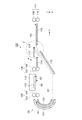
図4は、用紙反転ユニット40を装着部20に装着した状態で、主走査方向Xから見た記録装置1の概略構成を示す断面図である。記録部13の上方には、カバー10を上部に備えた画像読取部11が配置される。装着部20の下方には、回動軸24を支点として揺動する揺動部材23に支持される給送ローラー22が備えられる。
FIG. 4 is a cross-sectional view illustrating a schematic configuration of the
用紙反転ユニット40の筐体は、背面壁部48、上部壁部49を含んで構成される。用紙反転ユニット40は、中間搬送駆動ローラー50、中間搬送駆動ローラー50の駆動回転により従動回転する従動ローラー51,52,53、回動軸44を支点として揺動する揺動部材45、回動軸46を支点として揺動する揺動部材47、を含んで構成される。また、用紙反転ユニット40は、背面壁部48と揺動部材45との間に設けられた壁部材43、開閉蓋9、差込口8を構成する部材を含む。
The housing of the
用紙カセット12に載置された用紙P1は、給送ローラー22の駆動回転により、分離斜面25を通り、壁部材43と実線に示す揺動部材45との間に形成された空間領域である搬送路S1に給送される。矢印方向に駆動回転する中間搬送駆動ローラー50と、従動ローラー52,53によって挟持された用紙P1は、実線に示す揺動部材47と中間搬送駆動ローラー50との間の空間領域である搬送路S2を通り、上部壁部49と、記録装置1に設けられた壁部21との間に形成された空間領域である搬送路S3に搬送され、壁部21の上部に形成された搬送面21aに沿って搬送される。
The paper P1 placed on the
搬送面21aに沿って搬送される用紙P1は、駆動回転する搬送駆動ローラー26と、搬送駆動ローラー26の駆動回転により従動回転する従動ローラー27とに挟持され、液体噴射ヘッド3と対向する位置を支持部材28に支持されて下流側に搬送される。
The paper P1 transported along the
主走査方向Xに往復移動する液体噴射ヘッド3によって、搬送される用紙P1にインクが噴射されて画像が記録される。用紙P1は、排出駆動ローラー29と、排出駆動ローラー29の駆動回転によって従動回転する従動ローラー30とに挟持され、搬送路形成部材31の上面に沿って下流側に搬送され、前面蓋部7が回動して形成された開口部から排出される。
The
破線に示すように開閉蓋9が背面側に回動された状態で、図2(a)の用紙P2が差込口8から挿入されると、破線に示すように揺動部材47の先端部が下方に回動し、差込口8の中間搬送駆動ローラー50側が開放される。
When the paper P2 in FIG. 2A is inserted from the
用紙P2は、駆動回転する中間搬送駆動ローラー50と従動ローラー53とに挟持されて搬送路S3に搬送される。そして、用紙P2は、搬送駆動ローラー26と従動ローラー27とによって搬送されながら、記録部13において画像が記録され、前面蓋部7が回動して形成された開口部から排出される。
The sheet P2 is nipped between the intermediate
次に、用紙反転ユニット40によって、用紙P1,P2が反転されて、用紙P1,P2の表面と裏面との両面に記録を行う動作について説明する。用紙カセット12から搬送路S1,S2を通り搬送された用紙P1、差込口8から挿入された用紙P2は、中間搬送駆動ローラー50と従動ローラー53によって下流側に搬送される。この時点では、用紙P1,P2は、表面が上方すなわち液体噴射ヘッド3側に向いた状態で、搬送駆動ローラー26と従動ローラー27とによって搬送され、記録部13において用紙P1,P2の表面に画像が記録される。
Next, a description will be given of an operation in which the sheets P1 and P2 are reversed by the
そして、表面に画像が記録された用紙P1,P2は、搬送駆動ローラー26の逆回転により、副走査方向Yにおける上流側(以降は、上流側という)に搬送され、矢印方向に駆動回転する中間搬送駆動ローラー50と、従動ローラー51とによって、従動ローラー51と揺動部材45との間の空間領域である搬送路S4に搬送される。
Then, the sheets P1 and P2 on which the images are recorded are conveyed to the upstream side in the sub-scanning direction Y (hereinafter referred to as the upstream side) by the reverse rotation of the
破線に示すように、揺動部材45は先端部が背面側に回動し、用紙P1,P2は搬送路S1に搬送される。そして、用紙P1,P2は、中間搬送駆動ローラー50と従動ローラー52,53とによって搬送路S2,S3を通り搬送される。この時点における用紙P1,P2は、裏面が上方を向いた姿勢で搬送面21aに沿って下流側に搬送され、搬送駆動ローラー26と従動ローラー27とによって搬送され、記録部13において用紙P1,P2の裏面に画像が記録される。
As shown by the broken line, the tip of the swinging
液体噴射ヘッド3の上流側には、用紙P1,P2の上流側および下流側の端部を検出する、例えば光学式の端部検出部32が備えられる。
On the upstream side of the
図3(c)は、レンズシート給送ユニット70の斜視図である。図5は、レンズシート給送ユニット70を、筐体5に設けられた装着部20に装着した状態で、記録装置1を背面側から見た外観斜視図である。装着部20には、図3(c)のレンズシート給送ユニット70を着脱可能に備えることが可能である。
FIG. 3C is a perspective view of the lens
図3(a)の装着部20には、図3(b)の用紙反転ユニット40または図3(c)のレンズシート給送ユニット70が着脱可能に装着される。すなわち、用紙反転ユニット40とレンズシート給送ユニット70のうちの一方が装着部20に装着状態にあるとき、他方は装着部20から取り外された状態にある。
The
ここで、レンズシートLSについて説明する。図8(a)は、レンズシートLSをレンチキュラーレンズLS1側から見た図である。レンチキュラーレンズLS1は、方向Hを長手方向とする複数のシリンドリカル凸レンズL(以降は、レンズLという)が、一定のピッチKで幅方向Wに並列配置された構成となっている。 Here, the lens sheet LS will be described. FIG. 8A shows the lens sheet LS viewed from the lenticular lens LS1 side. The lenticular lens LS1 has a configuration in which a plurality of cylindrical convex lenses L (hereinafter referred to as lenses L) having a direction H as a longitudinal direction are arranged in parallel in the width direction W at a constant pitch K.
図8(b)は、方向Hから見たレンズシートLSの概略構成を示す断面図である。レンズシートLSは、表面に位置するレンチキュラーレンズLS1と、このレンチキュラーレンズLS1の裏面と接するインク吸収層LS2と、レンズシートLSの裏面に位置するインク透過層LS3とを具備している。レンチキュラーレンズLS1においては、それぞれのレンズLを進行する光の焦点が、レンチキュラーレンズLS1の裏面に位置するように、レンズLの曲率が形成される。 FIG. 8B is a cross-sectional view illustrating a schematic configuration of the lens sheet LS viewed from the direction H. The lens sheet LS includes a lenticular lens LS1 located on the front surface, an ink absorption layer LS2 in contact with the back surface of the lenticular lens LS1, and an ink transmission layer LS3 located on the back surface of the lens sheet LS. In the lenticular lens LS1, the curvature of the lens L is formed so that the focal point of the light traveling through each lens L is located on the back surface of the lenticular lens LS1.
インク透過層LS3は、不図示のノズルから噴射されたインク滴が最初に付着する部分であり、付着したインクが透過していく部分である。このインク透過層LS3は、たとえば酸化チタン、シリカゲル、PMMA(メタクリル樹脂)等の微粒子、硫酸バリウム、ガラスファイバー、プラスチックファイバー等を材質として形成されている。また、インク吸収層LS2は、インク透過層LS3を透過したインクを吸収し固着させる部位である。このインク吸収層LS2は、たとえばPVA(ポリビニルアルコール)等の親水性ポリマー樹脂、カチオン化合物、シリカ等の微粒子等を材質として形成されている。また、レンチキュラーレンズLS1は、PET、PETG、APET、PP、PS、PVC、アクリル、UV樹脂等を材質として形成されている。 The ink permeable layer LS3 is a portion to which an ink droplet ejected from a nozzle (not shown) first adheres, and is a portion through which the adhered ink passes. This ink transmission layer LS3 is made of, for example, fine particles such as titanium oxide, silica gel, PMMA (methacrylic resin), barium sulfate, glass fiber, plastic fiber, and the like. The ink absorption layer LS2 is a part that absorbs and fixes the ink that has passed through the ink transmission layer LS3. The ink absorption layer LS2 is formed of, for example, a hydrophilic polymer resin such as PVA (polyvinyl alcohol), a cationic compound, fine particles such as silica, or the like. The lenticular lens LS1 is made of PET, PETG, APET, PP, PS, PVC, acrylic, UV resin, or the like.
なお、インク吸収層LS2は透明であると共に、インク透過層LS3は、白色である。しかしながら、インク吸収層LS2が白色であっても良く、またインク透過層LS3が透明であっても良く、さらにインク透過層LS3とインク吸収層LS2の両方が透明であっても良い。また、本実施例では、インク透過層LS3が存在することにより、印刷後であっても、レンズシートLSを直ぐに触ることが可能となっている。しかしながら、レンズシートLSは、インク透過層LS3を具備しない構成を採用しても良い。 The ink absorption layer LS2 is transparent, and the ink transmission layer LS3 is white. However, the ink absorption layer LS2 may be white, the ink transmission layer LS3 may be transparent, and both the ink transmission layer LS3 and the ink absorption layer LS2 may be transparent. In the present embodiment, the presence of the ink transmission layer LS3 allows the lens sheet LS to be touched immediately even after printing. However, the lens sheet LS may adopt a configuration that does not include the ink transmission layer LS3.
また、図8(a)に示すように、本実施例におけるレンズシートLSは矩形状の外観を有し、レンズシートLSの幅方向Wの両端部(方向Hに延びる縁部)が、レンズLの長手方向と平行となっている。 Further, as shown in FIG. 8A, the lens sheet LS in the present embodiment has a rectangular appearance, and both end portions (edge portions extending in the direction H) of the lens sheet LS in the width direction W are the lens L. It is parallel to the longitudinal direction.
図6(a)は、レンズシート給送ユニット70の斜視図である。レンズシート給送ユニット70は、底部76、底部76の主走査方向Xにおける両側に設けられて上方に立設する立設部75a,75bを有する。
FIG. 6A is a perspective view of the lens
底部76の上部における主走査方向Xにおける両側には、レンズシートLSの主走査方向Xにおける両端部の位置を規制するエッジガイド72a,72bが、主走査方向Xにスライド可能に備えられる。エッジガイド72a,72bは、底部76から上方に立設するとともに、副走査方向Yに延在する形状である。
Edge guides 72a and 72b for regulating the positions of both end portions of the lens sheet LS in the main scanning direction X are provided on both sides of the upper portion of the
底部76の上部には、シートガイド71が設けられる。シートガイド71は、エッジガイド72a,72bによってレンズシートLSの両端部が規制される主走査方向Xにおける最大の範囲内に設けられる。また、シートガイド71は、底部76の上部における副走査方向Yにおいては、エッジガイド72a,72bが設けられた範囲を除いて、前面側の端部から背面側の端部まで設けられる。
A
図6(b)は、底部76の上部に設けられたシートガイド71の破線Rで示した円内の部分を拡大した図である。図6(c)は、シートガイド71と、シートガイド71の上部に載置されたレンズシートLSを、副走査方向Yから見た断面図である。
FIG. 6B is an enlarged view of a portion in a circle indicated by a broken line R of the
図6(c)のシートガイド71は、基板710と複数の凸部711とを備えている。基板710は、樹脂等から形成される板状部材である。凸部711は、本実施形態では、レンズシートLSのレンチキュラーレンズLS1と同一形状に形成され、図8(b)のレンチキュラーレンズLS1の配設ピッチKと同一ピッチに形成される。また、凸部711は、図6(b)に示すように、副走査方向Yに延びるようにして連続して形成される。
The
本実施形態では、シートガイド71は、基板710にレンチキュラーレンズLS1と同一部材である凸部711が貼付されて構成される。
In the present embodiment, the
尚、基板710を樹脂成形により作成する場合には、成形金型に予め凸部711に対応する型面を形成して、凸部711を基板710と一体に成形するようにしても良い。また、基板710に凸部711を一体に樹脂成形する場合には、基板710を形成する樹脂材をフッ素樹脂等の低摩擦の樹脂材とすることで、レンズシートLSと凸部711との摩擦を小さくすることができ、レンズシートLSの搬送を滑らかに行うことができる。また、基板710を金属板により形成してもよい。この場合には、金属板を切削加工することにより凸部711を形成することができる。
Note that when the
図6(a)の底部76の上方には、回転軸77と同軸上に設けられた給送ローラー74が備えられる。回転軸77は、立設部75a,75bに設けられた軸受け部(不図示)によって回転可能に備えられる。
A feeding
底部76の上方における給送ローラー74の上流側には、押圧ローラー73が備えられる。押圧ローラー73は、立設部75a,75bに設けられた、鉛直方向Zの位置が変動可能な軸受け部(不図示)によって回転可能に備えられる。
A
図7は、レンズシート給送ユニット70によりレンズシートLSを給送する状態を示す断面図である。図7は、用紙反転ユニット40が装着部20から取り外され、レンズシート給送ユニット70が装着部20に装着された状態にある。
FIG. 7 is a cross-sectional view showing a state in which the lens sheet LS is fed by the lens
レンズシート給送ユニット70が装着部20に装着された状態で、給送ローラー74を備えた回転軸77は、歯車などによって構成される伝達機構(不図示)によって回転駆動力を得て回転する。これにより、レンズシートLSは、シートガイド71上をスライド移動し、下流側に給送される。
In a state where the lens
また、押圧ローラー73は、シートガイド71上をスライド移動するレンズシートLSを押圧した状態で回転する。これにより、図6(c)のレンズシートLSのレンチキュラーレンズLS1と、シートガイド71の凸部711との嵌合状態が維持されるので、シートガイド71に対してレンズシートLSが移動することを規制する。
The
副走査方向Yにおいて、給送ローラー74によって下流側に搬送されるレンズシートLSの上流側および下流側の端部は、端部検出部32によって検出される。
In the sub-scanning direction Y, the upstream end portion and the downstream end portion of the lens sheet LS conveyed downstream by the feeding
さらに、レンズシートLSは、記録部13において画像が記録され、前面蓋部7が回動して形成された開口部から排出される。
Further, the lens sheet LS has an image recorded in the
図10は、レンズシートLSを搭載したトレイ80を示す図である。レンズシートLSが搭載されたトレイ80を、図6(a)のレンズシート給送ユニット70によって給送するようにしてもよい。
FIG. 10 is a view showing a
トレイ80は、鉛直方向Zから見た外形形状が矩形状を有し、上端面より窪んだ矩形状の凹部81を有する。凹部81には、レンズシートLSが収容される。凹部81には、レンズシートLSの端部を主走査方向Xにおいて押圧する押圧部材82と、レンズシートLSの端部を副走査方向Yにおいて押圧する押圧部材83とが備えられる。これにより、レンズシートLSの位置がトレイ80に対して固定される。
The
また、図7に示すように、用紙反転ユニット40が装着部20から取り外された状態では、記録部13の上流側が開放された状態となる。これにより、記録装置1は、筐体5の前面側から挿入されたレンズシートLSに対しても記録を行うことが可能である。使用者は、図4の操作パネル6、前面蓋部7を前面側にそれぞれ回動し、記録装置1の前面側が開口した状態で、レンズシートLSを挿入する。
Further, as shown in FIG. 7, when the
記録装置1は、排出駆動ローラー29、従動ローラー30、搬送駆動ローラー26、従動ローラー27を用いて、レンズシートLSを上流側に搬送する。そして、記録装置1は、レンズシートLSを下流側に搬送しながら、記録部13によってレンズシートLSに記録を行う。レンズシートLSを上流側に搬送するときに、記録部13によってレンズシートLSに記録を行うようにしてもよい。
The
用紙P1,P2は、第1の被記録媒体である。第1の被記録媒体は、紙材などの柔軟な部材で構成されたものであり、第1の被記録媒体が湾曲した搬送経路を通ることにより、湾曲した搬送経路で停止したり、損傷を受けることがない。 The sheets P1 and P2 are first recording media. The first recording medium is composed of a flexible member such as a paper material. When the first recording medium passes through the curved conveyance path, the first recording medium stops on the curved conveyance path or is damaged. I do not receive it.
レンズシートLSは、第2の被記録媒体である。第2の被記録媒体は、樹脂や金属などの部材を含んで構成されたものである。また、厚い紙材で構成されたものも第2の被記録媒体に含まれる。第2の被記録媒体は、第1の被記録媒体より剛性が高い。 The lens sheet LS is a second recording medium. The second recording medium is configured to include a member such as resin or metal. The second recording medium includes a thick paper material. The second recording medium has higher rigidity than the first recording medium.
用紙反転ユニット40は、第1搬送装置を構成する。図4の用紙反転ユニット40には、中間搬送駆動ローラー50の外周側に、搬送路S1,S2,S4によって湾曲した湾曲反転経路が設けられる。
The
レンズシート給送ユニット70は、第2搬送装置を構成する。図7のレンズシート給送ユニット70には、壁部21の搬送面21aに沿って直線状に搬送する直線搬送経路が設けられる。
The lens
以上、本実施形態で説明した記録装置1は、装置本体としての筐体5と、筐体5の内部に設けられ、用紙P1,P2、用紙P1,P2より剛性の高いレンズシートLSに記録する記録部13と、搬送装置(用紙反転ユニット40、レンズシート給送ユニット70)を装着する装着部20と、用紙P1を収容する第1の被記録媒体収容部としての用紙カセット12と、用紙カセット12から送り出された用紙P1を湾曲反転させて記録部13へ案内する湾曲反転経路を有し、前記湾曲反転経路の構成部材がユニット化され、装着部20に着脱可能に備えられる第1搬送装置としての用紙反転ユニット40と、を備える。そして、装着部20には、レンズシートLSを直線搬送可能な第2搬送装置としてのレンズシート給送ユニット70が装着され、レンズシートLSを記録部13によって記録を行う。
As described above, the
この構成によれば、記録装置1は、大型化することなく、用紙P1,P2および用紙P1,P2より剛性の高いレンズシートLSを搬送させることができる。
According to this configuration, the
また、レンズシート給送ユニット70は、図10のレンズシートLSを載置するトレイ80を搬送する。これにより、トレイ80に載置された状態で搬送することによってレンズシートLSの位置が変動することを抑制できる。
Further, the lens
また、装置前面または背面のいずれか一方からレンズシートLSを搬送可能である。これにより、レンズシートLSを筐体5の外側から内部に給送する方向において、使用者にとっての選択肢が増える。
Further, the lens sheet LS can be conveyed from either the front surface or the back surface of the apparatus. This increases the options for the user in the direction of feeding the lens sheet LS from the outside of the
また、記録部13に設けられて、液体としてのインクを噴射する液体噴射ヘッド3と、液体噴射ヘッド3と対向する位置に、レンズシートLSまたはトレイ80を支持する支持面を有する支持部材28と、を備え、レンズシート給送ユニット70の装着時において、レンズシート給送ユニット70の搬送面(シートガイド71によって構成される搬送面)と、支持部材28の支持面とは略同一面で形成される。
Further, a
これにより、レンズシートLSは曲げられることなく搬送されるので、レンズシートLSが損傷したり、搬送面や支持面で停止することがない。 Thereby, since the lens sheet LS is conveyed without being bent, the lens sheet LS is not damaged or stopped at the conveyance surface or the support surface.
また、レンズシート給送ユニット70は、レンズシートLSまたはトレイ80を押圧する押圧ローラー73を備える。
The lens
これによれば、図6(c)のレンズシートLSのレンチキュラーレンズLS1と、シートガイド71の凸部711との嵌合状態が維持されるので、シートガイド71に対してレンズシートLSが移動することを抑制できる。
According to this, since the fitting state between the lenticular lens LS1 of the lens sheet LS of FIG. 6C and the
また、レンズシート給送ユニット70は、レンズシートLSを搬送する搬送駆動ローラーとしての給送ローラー74を備える。これにより、レンズシートLSを記録部13側に搬送することができる。
Further, the lens
また、給送ローラー74は、用紙P1,P2を搬送する駆動力によって、駆動される。これにより、給送ローラー74を駆動するための駆動力を発生する駆動機構を別に設けなくてもよいので、記録装置1が大型化することを抑制できる。
Further, the feeding
また、レンズシート給送ユニット70は、レンズシートLSの搬送方向と交わる方向(主走査方向X)の端部の位置を規制するとともに、レンズシートLSの搬送方向をガイドするガイド部としてのエッジガイド72a,72bを備える。これにより、レンズシートLSに形成される画像品質の低下を抑制できる。
Further, the lens
また、レンズシート給送ユニット70は、図6(b)のシートガイド71を備え、シートガイド71は、レンズシートLSの搬送方向と交わる方向(主走査方向X)において、レンズシートLSのレンズLによって形成される凹凸部と嵌合する嵌合部としての複数の凸部711を備える。この構成により、主走査方向XにおけるレンズシートLSの位置を定めることができる。
Further, the lens
また、用紙反転ユニット40は、被記録面が反転された姿勢の用紙P1,P2を搬送する。これにより、用紙反転ユニット40を用いて、用紙P1,P2の被記録面を反転させることができる。
Further, the
また、レンズシートLSは、視差変化による立体視可能な画像を形成する構成を備える。これにより、記録装置1によって、視差変化による立体視可能な画像をレンズシートLSに形成することができる。
In addition, the lens sheet LS includes a configuration that forms a stereoscopically viewable image by changing the parallax. Thereby, the
また、用紙反転ユニット40は、用紙P2を傾斜した姿勢で収容する、第2の被記録媒体収容部としての差込口8を上部に設け、差込口8から記録部13へ用紙P2を搬送する搬送経路を備える。
In addition, the
この構成によれば、用紙P2を記録部13に給送する手段において、使用者にとっての選択肢が増えるとともに、記録装置1が大型化することを抑制できる。
According to this configuration, in the means for feeding the paper P2 to the
本実施形態の図4の記録装置1は、記録部13の上流側に、用紙P1,P2の搬送経路が交差する部分(搬送路S3)が設けられたが、本発明は、用紙の搬送経路が交差する部分を、記録部の下流側に設けた記録装置にも適用する。
In the
図9は、主走査方向から見た図で、用紙の搬送経路が交差する部分を、記録部の下流側に設けた記録装置120の概略構成を示す図である。記録装置120には、内側壁部102と外側壁部101との間に湾曲経路が構成された用紙反転部100が備えられる。また、主走査方向に往復移動するキャリッジ112に備えられた液体噴射ヘッド113を含んで構成される記録部の下流側に、用紙の搬送経路が交差する部分C(破線の円内)が設けられる。用紙の搬送経路が交差する部分Cには、軸118を支点として揺動する揺動部材117が設けられる。
FIG. 9 is a diagram illustrating a schematic configuration of the
液体噴射ヘッド113の上流側には、ローラー103,104のうちの一方を駆動ローラーとし他方を従動ローラーとするローラー対105が備えられる。液体噴射ヘッド113の下流側には、ローラー106,107のうちの一方を駆動ローラーとし他方を従動ローラーとするローラー対108、ローラー109,110のうちの一方を駆動ローラーとし他方を従動ローラーとするローラー対111が備えられる。
On the upstream side of the
実線矢印A1,A2に示すように、用紙が、用紙反転部100を通り、ローラー対105,108によって、搬送面を構成する部材114に沿って下流側(図面右側)に搬送される。搬送される用紙は、液体噴射ヘッド113と対向する位置において一方の被記録面に画像が形成される。
As indicated by solid line arrows A1 and A2, the sheet passes through the
実線矢印A3に示すように、用紙は、揺動部材117が実線に示した回動位置にあって搬送経路が開放された状態にあるので、ローラー対111によって、搬送面を構成する部材115に沿って下流側に搬送される。
As indicated by the solid line arrow A3, the sheet is in a state where the swinging
そして、用紙は、ローラー対111の逆回転によって、上流側(図面左側)に搬送される。このとき、揺動部材117が破線に示した位置に回動し、部材114側の搬送経路が閉じ、部材116側の搬送経路が開放されることにより、破線矢印B1に示すように、用紙は、搬送面を構成する部材116に沿って搬送される。そして、用紙は、再び用紙反転部100の湾曲経路を通り、液体噴射ヘッド113と対向する位置を通り、他方の被記録面に画像が形成される。
Then, the sheet is conveyed to the upstream side (left side in the drawing) by the reverse rotation of the
1,120…記録装置、5…筐体、8…差込口、12…用紙カセット、13…記録部、20…装着部、28…支持部材、40…用紙反転ユニット、70…レンズシート給送ユニット、71…シートガイド、72a,72b…エッジガイド、73…押圧ローラー、74…給送ローラー、77…回転軸、80…トレイ、82,83…ガイド部材、711…凸部、P1,P2…用紙、S1,S2,S3,S4…搬送路、LS…レンズシート。 DESCRIPTION OF SYMBOLS 1,120 ... Recording device, 5 ... Case, 8 ... Inlet, 12 ... Paper cassette, 13 ... Recording part, 20 ... Mounting part, 28 ... Support member, 40 ... Paper reversing unit, 70 ... Lens sheet feeding Unit: 71 ... sheet guide, 72a, 72b ... edge guide, 73 ... pressing roller, 74 ... feed roller, 77 ... rotating shaft, 80 ... tray, 82,83 ... guide member, 711 ... convex, P1, P2 ... Paper, S1, S2, S3, S4 ... conveying path, LS ... lens sheet.
Claims (13)
前記第1の被記録媒体を湾曲反転させ前記記録部へ案内する湾曲反転経路を有する第1搬送装置と、前記第2の被記録媒体を直線搬送可能な第2搬送装置と、
前記記録部が記録を行う被記録媒体の種類に応じて、前記第1搬送装置及び前記第2搬送装置を選択可能に装着可能な装着部と、
前記装置本体内部に設けられ、前記第2の被記録媒体を搬送可能な搬送経路と、を有し、
前記第2搬送装置の搬送面は、前記搬送経路の搬送面と略同一面であることを特徴とする記録装置。 An apparatus main body, and the device provided inside the main body, a recording section for recording the second recording medium including a rigidity high rather resin or metal from the first recording medium and the first recording medium,
A first transport device having a curved reversing path for curving and reversing the first recording medium and guiding the recording medium; a second transport device capable of linearly transporting the second recording medium;
A mounting unit capable of selectively mounting the first transport device and the second transport device according to the type of recording medium on which the recording unit performs recording ,
A conveyance path provided inside the apparatus main body and capable of conveying the second recording medium ,
The conveying surface of the second transport device, recording apparatus characterized substantially flush der Rukoto and transport surface of the transport path.
前記第2の被記録媒体は、前記第2の被記録媒体の搬送方向の一方向側である装置前面、または、前記搬送方向の他方向側である装置背面から給送されることを特徴とする記録装置。 The recording apparatus according to claim 1 ,
It said second recording medium, and the second front surface of the apparatus is a one-way side in the transport direction of the recording medium, or characterized in that it is fed from the rear of the unit is the other side of the transport direction Recording device.
前記第2搬送装置は、前記装置背面に設けられた前記装着部に装着され、前記装置背面から突出しないことを特徴とする記録装置。 The recording apparatus, wherein the second transport device is mounted on the mounting portion provided on the back surface of the device and does not protrude from the back surface of the device.
前記第1搬送装置及び前記第2搬送装置を前記装着部に装着するときの方向は同じであることを特徴とする記録装置。 The recording apparatus according to claim 1, wherein directions when the first transport device and the second transport device are mounted on the mounting portion are the same.
前記第2搬送装置は、前記第2の被記録媒体を載置するトレイを搬送することを特徴とする記録装置。 The recording apparatus according to claim 1 , wherein:
The recording apparatus, wherein the second transport device transports a tray on which the second recording medium is placed.
前記記録部に備えられて、液体を噴射する液体噴射ヘッドと、
前記液体噴射ヘッドと対向する位置に、前記第2の被記録媒体または前記トレイを支持する支持面を有する支持部材と、を備え、
前記第2搬送装置の装着時において、前記第2搬送装置の搬送面と、前記支持部材の前記支持面とは略同一面で形成されることを特徴とする記録装置。 The recording apparatus according to claim 5 ,
A liquid ejecting head that is provided in the recording unit and ejects liquid;
A support member having a support surface for supporting the second recording medium or the tray at a position facing the liquid ejecting head;
The recording apparatus according to claim 1, wherein when the second transport device is mounted, the transport surface of the second transport device and the support surface of the support member are formed on substantially the same surface.
前記第2搬送装置は、前記第2の被記録媒体または前記トレイを押圧する押圧ローラーを備えることを特徴とする記録装置。 The recording apparatus according to claim 5 or 6 , wherein
The recording apparatus, wherein the second transport device includes a pressing roller that presses the second recording medium or the tray.
前記第2搬送装置は、前記第2の被記録媒体を搬送する搬送駆動ローラーを備えることを特徴とする記録装置。 The recording apparatus according to any one of claims 1 to 7 ,
The recording apparatus, wherein the second transport device includes a transport driving roller for transporting the second recording medium.
前記搬送駆動ローラーは、前記第1の被記録媒体を搬送する駆動力によって、駆動されることを特徴とする記録装置。 The recording apparatus according to claim 8 , wherein
The recording apparatus, wherein the transport driving roller is driven by a driving force for transporting the first recording medium.
前記第2搬送装置は、前記第2の被記録媒体の搬送方向と交わる方向の端部の位置を規制するとともに、前記第2の被記録媒体の搬送方向をガイドするガイド部を備えることを特徴とする記録装置。 The recording apparatus according to any one of claims 1 to 9 ,
The second transport device includes a guide portion that regulates a position of an end portion in a direction intersecting a transport direction of the second recording medium and guides the transport direction of the second recording medium. A recording device.
前記第2搬送装置は、前記第2の被記録媒体の搬送方向と交わる方向において、前記第2の被記録媒体の凹凸部と嵌合する嵌合部を備えることを特徴とする記録装置。 The recording apparatus according to any one of claims 1 to 10 ,
The recording apparatus, wherein the second transport device includes a fitting portion that fits with a concavo-convex portion of the second recording medium in a direction intersecting the transport direction of the second recording medium.
前記第1搬送装置は、被記録面が反転された姿勢の前記第1の被記録媒体を搬送することを特徴とする記録装置。 The recording apparatus according to any one of claims 1 to 11 ,
The recording apparatus, wherein the first transport apparatus transports the first recording medium in a posture in which a recording surface is inverted.
前記第2の被記録媒体は、レンズシートであることを特徴とする記録装置。 The recording apparatus, wherein the second recording medium is a lens sheet.
Priority Applications (2)
| Application Number | Priority Date | Filing Date | Title |
|---|---|---|---|
| JP2013266619A JP6281281B2 (en) | 2013-12-25 | 2013-12-25 | Recording device |
| US14/582,577 US9199490B2 (en) | 2013-12-25 | 2014-12-24 | Recording device |
Applications Claiming Priority (1)
| Application Number | Priority Date | Filing Date | Title |
|---|---|---|---|
| JP2013266619A JP6281281B2 (en) | 2013-12-25 | 2013-12-25 | Recording device |
Publications (3)
| Publication Number | Publication Date |
|---|---|
| JP2015120319A JP2015120319A (en) | 2015-07-02 |
| JP2015120319A5 JP2015120319A5 (en) | 2017-01-19 |
| JP6281281B2 true JP6281281B2 (en) | 2018-02-21 |
Family
ID=53532425
Family Applications (1)
| Application Number | Title | Priority Date | Filing Date |
|---|---|---|---|
| JP2013266619A Active JP6281281B2 (en) | 2013-12-25 | 2013-12-25 | Recording device |
Country Status (1)
| Country | Link |
|---|---|
| JP (1) | JP6281281B2 (en) |
Families Citing this family (5)
| Publication number | Priority date | Publication date | Assignee | Title |
|---|---|---|---|---|
| JP6730657B2 (en) * | 2016-02-01 | 2020-07-29 | セイコーエプソン株式会社 | Recording device |
| JP6891567B2 (en) * | 2017-03-17 | 2021-06-18 | 富士フイルムビジネスイノベーション株式会社 | Image forming device |
| JP7099130B2 (en) * | 2018-07-27 | 2022-07-12 | セイコーエプソン株式会社 | Printing equipment |
| JP7380135B2 (en) | 2019-11-27 | 2023-11-15 | セイコーエプソン株式会社 | Media transport equipment and processing equipment |
| JP7439503B2 (en) | 2019-12-26 | 2024-02-28 | セイコーエプソン株式会社 | Media transport equipment and processing equipment |
Family Cites Families (4)
| Publication number | Priority date | Publication date | Assignee | Title |
|---|---|---|---|---|
| JPH05162413A (en) * | 1991-12-11 | 1993-06-29 | Casio Electron Mfg Co Ltd | Assembling image formation apparatus |
| JP4765564B2 (en) * | 2005-11-08 | 2011-09-07 | セイコーエプソン株式会社 | Print media transport tray |
| JP2010247961A (en) * | 2009-04-16 | 2010-11-04 | Seiko Epson Corp | Recording device and transfer method |
| JP2013166390A (en) * | 2013-05-16 | 2013-08-29 | Seiko Epson Corp | Recording device |
-
2013
- 2013-12-25 JP JP2013266619A patent/JP6281281B2/en active Active
Also Published As
| Publication number | Publication date |
|---|---|
| JP2015120319A (en) | 2015-07-02 |
Similar Documents
| Publication | Publication Date | Title |
|---|---|---|
| JP6281281B2 (en) | Recording device | |
| US9387694B2 (en) | Recording apparatus | |
| JP4238994B2 (en) | Sheet-like member conveying apparatus and information processing apparatus having the conveying apparatus | |
| JP5041046B2 (en) | Recording device | |
| JP6446946B2 (en) | Conveying apparatus and inkjet recording apparatus | |
| US9199490B2 (en) | Recording device | |
| JP6402975B2 (en) | Image reading device | |
| JP6322998B2 (en) | Recording device | |
| JP6295648B2 (en) | Recording device | |
| JP2020164290A (en) | Sheet feeding device | |
| JP2019214176A (en) | Printer | |
| US9409736B2 (en) | Sheet conveying device and image recording apparatus | |
| JP6326842B2 (en) | Image reading device | |
| JP5910030B2 (en) | Image recording device | |
| US9527289B2 (en) | Recording device | |
| JP6288422B2 (en) | Recording device | |
| JP6337650B2 (en) | Image reading device | |
| JP6528958B2 (en) | Recording device | |
| JP6882712B2 (en) | Recording device | |
| JP2021095235A (en) | Image recording apparatus | |
| JP2016064890A (en) | Image recording device | |
| JP2011190028A (en) | Image recording device | |
| JP5772056B2 (en) | Medium transport mechanism and recording apparatus provided with the same | |
| JP5787070B2 (en) | Recording device | |
| JP2011148215A (en) | Recording apparatus |
Legal Events
| Date | Code | Title | Description |
|---|---|---|---|
| RD04 | Notification of resignation of power of attorney |
Free format text: JAPANESE INTERMEDIATE CODE: A7424 Effective date: 20160617 |
|
| RD03 | Notification of appointment of power of attorney |
Free format text: JAPANESE INTERMEDIATE CODE: A7423 Effective date: 20160627 |
|
| A521 | Written amendment |
Free format text: JAPANESE INTERMEDIATE CODE: A523 Effective date: 20161206 |
|
| A621 | Written request for application examination |
Free format text: JAPANESE INTERMEDIATE CODE: A621 Effective date: 20161206 |
|
| A977 | Report on retrieval |
Free format text: JAPANESE INTERMEDIATE CODE: A971007 Effective date: 20171016 |
|
| A131 | Notification of reasons for refusal |
Free format text: JAPANESE INTERMEDIATE CODE: A131 Effective date: 20171024 |
|
| A521 | Written amendment |
Free format text: JAPANESE INTERMEDIATE CODE: A523 Effective date: 20171201 |
|
| TRDD | Decision of grant or rejection written | ||
| A01 | Written decision to grant a patent or to grant a registration (utility model) |
Free format text: JAPANESE INTERMEDIATE CODE: A01 Effective date: 20171226 |
|
| A61 | First payment of annual fees (during grant procedure) |
Free format text: JAPANESE INTERMEDIATE CODE: A61 Effective date: 20180108 |
|
| R150 | Certificate of patent or registration of utility model |
Ref document number: 6281281 Country of ref document: JP Free format text: JAPANESE INTERMEDIATE CODE: R150 |