JP6280147B2 - Unmanned work vehicle - Google Patents
Unmanned work vehicle Download PDFInfo
- Publication number
- JP6280147B2 JP6280147B2 JP2016055548A JP2016055548A JP6280147B2 JP 6280147 B2 JP6280147 B2 JP 6280147B2 JP 2016055548 A JP2016055548 A JP 2016055548A JP 2016055548 A JP2016055548 A JP 2016055548A JP 6280147 B2 JP6280147 B2 JP 6280147B2
- Authority
- JP
- Japan
- Prior art keywords
- sign
- work vehicle
- image
- camera
- unit
- Prior art date
- Legal status (The legal status is an assumption and is not a legal conclusion. Google has not performed a legal analysis and makes no representation as to the accuracy of the status listed.)
- Expired - Fee Related
Links
- 238000010191 image analysis Methods 0.000 claims description 60
- 238000000034 method Methods 0.000 claims description 53
- 239000000284 extract Substances 0.000 claims description 18
- 239000003550 marker Substances 0.000 description 45
- 238000003384 imaging method Methods 0.000 description 22
- 238000001514 detection method Methods 0.000 description 20
- 230000008569 process Effects 0.000 description 17
- 230000001133 acceleration Effects 0.000 description 13
- 239000000758 substrate Substances 0.000 description 13
- 238000013459 approach Methods 0.000 description 8
- 230000004888 barrier function Effects 0.000 description 6
- 230000000694 effects Effects 0.000 description 3
- 244000025254 Cannabis sativa Species 0.000 description 2
- 238000010586 diagram Methods 0.000 description 2
- 230000002452 interceptive effect Effects 0.000 description 2
- 241001520823 Zoysia Species 0.000 description 1
- 230000009471 action Effects 0.000 description 1
- 238000004458 analytical method Methods 0.000 description 1
- 230000000903 blocking effect Effects 0.000 description 1
- 230000006870 function Effects 0.000 description 1
- 230000005484 gravity Effects 0.000 description 1
- 230000006872 improvement Effects 0.000 description 1
- 239000000203 mixture Substances 0.000 description 1
- 239000011435 rock Substances 0.000 description 1
- 239000004575 stone Substances 0.000 description 1
- 239000002023 wood Substances 0.000 description 1
Images


Classifications
-
- G—PHYSICS
- G05—CONTROLLING; REGULATING
- G05D—SYSTEMS FOR CONTROLLING OR REGULATING NON-ELECTRIC VARIABLES
- G05D1/00—Control of position, course or altitude of land, water, air, or space vehicles, e.g. automatic pilot
- G05D1/02—Control of position or course in two dimensions
- G05D1/021—Control of position or course in two dimensions specially adapted to land vehicles
- G05D1/0231—Control of position or course in two dimensions specially adapted to land vehicles using optical position detecting means
- G05D1/0246—Control of position or course in two dimensions specially adapted to land vehicles using optical position detecting means using a video camera in combination with image processing means
- G05D1/0253—Control of position or course in two dimensions specially adapted to land vehicles using optical position detecting means using a video camera in combination with image processing means extracting relative motion information from a plurality of images taken successively, e.g. visual odometry, optical flow
-
- G—PHYSICS
- G06—COMPUTING; CALCULATING OR COUNTING
- G06T—IMAGE DATA PROCESSING OR GENERATION, IN GENERAL
- G06T7/00—Image analysis
- G06T7/70—Determining position or orientation of objects or cameras
- G06T7/73—Determining position or orientation of objects or cameras using feature-based methods
- G06T7/74—Determining position or orientation of objects or cameras using feature-based methods involving reference images or patches
-
- A—HUMAN NECESSITIES
- A01—AGRICULTURE; FORESTRY; ANIMAL HUSBANDRY; HUNTING; TRAPPING; FISHING
- A01D—HARVESTING; MOWING
- A01D34/00—Mowers; Mowing apparatus of harvesters
- A01D34/006—Control or measuring arrangements
- A01D34/008—Control or measuring arrangements for automated or remotely controlled operation
-
- A—HUMAN NECESSITIES
- A01—AGRICULTURE; FORESTRY; ANIMAL HUSBANDRY; HUNTING; TRAPPING; FISHING
- A01D—HARVESTING; MOWING
- A01D34/00—Mowers; Mowing apparatus of harvesters
- A01D34/01—Mowers; Mowing apparatus of harvesters characterised by features relating to the type of cutting apparatus
- A01D34/412—Mowers; Mowing apparatus of harvesters characterised by features relating to the type of cutting apparatus having rotating cutters
- A01D34/63—Mowers; Mowing apparatus of harvesters characterised by features relating to the type of cutting apparatus having rotating cutters having cutters rotating about a vertical axis
- A01D34/64—Mowers; Mowing apparatus of harvesters characterised by features relating to the type of cutting apparatus having rotating cutters having cutters rotating about a vertical axis mounted on a vehicle, e.g. a tractor, or drawn by an animal or a vehicle
-
- A—HUMAN NECESSITIES
- A01—AGRICULTURE; FORESTRY; ANIMAL HUSBANDRY; HUNTING; TRAPPING; FISHING
- A01D—HARVESTING; MOWING
- A01D34/00—Mowers; Mowing apparatus of harvesters
- A01D34/01—Mowers; Mowing apparatus of harvesters characterised by features relating to the type of cutting apparatus
- A01D34/412—Mowers; Mowing apparatus of harvesters characterised by features relating to the type of cutting apparatus having rotating cutters
- A01D34/63—Mowers; Mowing apparatus of harvesters characterised by features relating to the type of cutting apparatus having rotating cutters having cutters rotating about a vertical axis
- A01D34/81—Casings; Housings
-
- B—PERFORMING OPERATIONS; TRANSPORTING
- B60—VEHICLES IN GENERAL
- B60W—CONJOINT CONTROL OF VEHICLE SUB-UNITS OF DIFFERENT TYPE OR DIFFERENT FUNCTION; CONTROL SYSTEMS SPECIALLY ADAPTED FOR HYBRID VEHICLES; ROAD VEHICLE DRIVE CONTROL SYSTEMS FOR PURPOSES NOT RELATED TO THE CONTROL OF A PARTICULAR SUB-UNIT
- B60W30/00—Purposes of road vehicle drive control systems not related to the control of a particular sub-unit, e.g. of systems using conjoint control of vehicle sub-units, or advanced driver assistance systems for ensuring comfort, stability and safety or drive control systems for propelling or retarding the vehicle
- B60W30/18—Propelling the vehicle
-
- G—PHYSICS
- G05—CONTROLLING; REGULATING
- G05D—SYSTEMS FOR CONTROLLING OR REGULATING NON-ELECTRIC VARIABLES
- G05D1/00—Control of position, course or altitude of land, water, air, or space vehicles, e.g. automatic pilot
- G05D1/0088—Control of position, course or altitude of land, water, air, or space vehicles, e.g. automatic pilot characterized by the autonomous decision making process, e.g. artificial intelligence, predefined behaviours
-
- G—PHYSICS
- G05—CONTROLLING; REGULATING
- G05D—SYSTEMS FOR CONTROLLING OR REGULATING NON-ELECTRIC VARIABLES
- G05D1/00—Control of position, course or altitude of land, water, air, or space vehicles, e.g. automatic pilot
- G05D1/02—Control of position or course in two dimensions
- G05D1/021—Control of position or course in two dimensions specially adapted to land vehicles
- G05D1/0212—Control of position or course in two dimensions specially adapted to land vehicles with means for defining a desired trajectory
- G05D1/0223—Control of position or course in two dimensions specially adapted to land vehicles with means for defining a desired trajectory involving speed control of the vehicle
-
- G—PHYSICS
- G05—CONTROLLING; REGULATING
- G05D—SYSTEMS FOR CONTROLLING OR REGULATING NON-ELECTRIC VARIABLES
- G05D1/00—Control of position, course or altitude of land, water, air, or space vehicles, e.g. automatic pilot
- G05D1/02—Control of position or course in two dimensions
- G05D1/021—Control of position or course in two dimensions specially adapted to land vehicles
- G05D1/0212—Control of position or course in two dimensions specially adapted to land vehicles with means for defining a desired trajectory
- G05D1/0225—Control of position or course in two dimensions specially adapted to land vehicles with means for defining a desired trajectory involving docking at a fixed facility, e.g. base station or loading bay
-
- G—PHYSICS
- G05—CONTROLLING; REGULATING
- G05D—SYSTEMS FOR CONTROLLING OR REGULATING NON-ELECTRIC VARIABLES
- G05D1/00—Control of position, course or altitude of land, water, air, or space vehicles, e.g. automatic pilot
- G05D1/02—Control of position or course in two dimensions
- G05D1/021—Control of position or course in two dimensions specially adapted to land vehicles
- G05D1/0231—Control of position or course in two dimensions specially adapted to land vehicles using optical position detecting means
- G05D1/0234—Control of position or course in two dimensions specially adapted to land vehicles using optical position detecting means using optical markers or beacons
-
- G—PHYSICS
- G05—CONTROLLING; REGULATING
- G05D—SYSTEMS FOR CONTROLLING OR REGULATING NON-ELECTRIC VARIABLES
- G05D1/00—Control of position, course or altitude of land, water, air, or space vehicles, e.g. automatic pilot
- G05D1/02—Control of position or course in two dimensions
- G05D1/021—Control of position or course in two dimensions specially adapted to land vehicles
- G05D1/0231—Control of position or course in two dimensions specially adapted to land vehicles using optical position detecting means
- G05D1/0246—Control of position or course in two dimensions specially adapted to land vehicles using optical position detecting means using a video camera in combination with image processing means
-
- G—PHYSICS
- G06—COMPUTING; CALCULATING OR COUNTING
- G06F—ELECTRIC DIGITAL DATA PROCESSING
- G06F18/00—Pattern recognition
- G06F18/20—Analysing
- G06F18/22—Matching criteria, e.g. proximity measures
-
- G—PHYSICS
- G06—COMPUTING; CALCULATING OR COUNTING
- G06T—IMAGE DATA PROCESSING OR GENERATION, IN GENERAL
- G06T7/00—Image analysis
- G06T7/70—Determining position or orientation of objects or cameras
- G06T7/73—Determining position or orientation of objects or cameras using feature-based methods
-
- G—PHYSICS
- G06—COMPUTING; CALCULATING OR COUNTING
- G06V—IMAGE OR VIDEO RECOGNITION OR UNDERSTANDING
- G06V20/00—Scenes; Scene-specific elements
- G06V20/50—Context or environment of the image
- G06V20/56—Context or environment of the image exterior to a vehicle by using sensors mounted on the vehicle
-
- A—HUMAN NECESSITIES
- A01—AGRICULTURE; FORESTRY; ANIMAL HUSBANDRY; HUNTING; TRAPPING; FISHING
- A01D—HARVESTING; MOWING
- A01D2101/00—Lawn-mowers
-
- B—PERFORMING OPERATIONS; TRANSPORTING
- B60—VEHICLES IN GENERAL
- B60W—CONJOINT CONTROL OF VEHICLE SUB-UNITS OF DIFFERENT TYPE OR DIFFERENT FUNCTION; CONTROL SYSTEMS SPECIALLY ADAPTED FOR HYBRID VEHICLES; ROAD VEHICLE DRIVE CONTROL SYSTEMS FOR PURPOSES NOT RELATED TO THE CONTROL OF A PARTICULAR SUB-UNIT
- B60W2420/00—Indexing codes relating to the type of sensors based on the principle of their operation
- B60W2420/40—Photo or light sensitive means, e.g. infrared sensors
- B60W2420/403—Image sensing, e.g. optical camera
-
- G—PHYSICS
- G06—COMPUTING; CALCULATING OR COUNTING
- G06T—IMAGE DATA PROCESSING OR GENERATION, IN GENERAL
- G06T2207/00—Indexing scheme for image analysis or image enhancement
- G06T2207/10—Image acquisition modality
- G06T2207/10016—Video; Image sequence
-
- G—PHYSICS
- G06—COMPUTING; CALCULATING OR COUNTING
- G06T—IMAGE DATA PROCESSING OR GENERATION, IN GENERAL
- G06T2207/00—Indexing scheme for image analysis or image enhancement
- G06T2207/30—Subject of image; Context of image processing
- G06T2207/30204—Marker
-
- G—PHYSICS
- G06—COMPUTING; CALCULATING OR COUNTING
- G06T—IMAGE DATA PROCESSING OR GENERATION, IN GENERAL
- G06T2207/00—Indexing scheme for image analysis or image enhancement
- G06T2207/30—Subject of image; Context of image processing
- G06T2207/30248—Vehicle exterior or interior
- G06T2207/30252—Vehicle exterior; Vicinity of vehicle
Description
本発明は、無人走行作業車に関する。本発明は、特に、無人走行作業車が作業を行う作業エリアの設定にかかるユーザーの労力を軽減可能な無人走行作業車に関する。 The present invention relates to an unmanned traveling work vehicle. In particular, the present invention relates to an unmanned traveling work vehicle that can reduce a user's labor for setting a work area where the unmanned traveling work vehicle performs work.
従来から、例えば芝刈り作業用ブレード等の作業装置を搭載し、設定された作業エリアを無人走行する間に作業装置を作動させる無人走行作業車が提案されている。無人走行作業車が無人走行する作業エリアは、例えばワイヤ等の物理的な障壁をユーザーが設置することによって設定される。そのため、無人走行作業車は、物理的な障壁に接触したときに例えば旋回して方向転換することによって、作業エリアの外を走行することがない。 2. Description of the Related Art Conventionally, there has been proposed an unmanned traveling vehicle equipped with a working device such as a lawn mowing blade and operating the working device while unmanned traveling in a set work area. The work area where the unmanned traveling work vehicle travels unattended is set by the user installing a physical barrier such as a wire. For this reason, the unmanned traveling work vehicle does not travel outside the work area, for example, by turning and turning when it touches a physical barrier.
ところで、物理的な障壁によって作業エリアを設定するためには、ユーザーが、作業エリアの内と外との境界の全体にわたって例えばワイヤ等の物理的な障壁を、無人走行作業車と接触する高さに設置する必要がある。ここで、特許文献1には、作業エリアの内と外との境界の位置情報を記憶すること可能な物理的な障壁を必要としないロボット芝刈機(無人走行作業車)が開示されている。
By the way, in order to set a work area with a physical barrier, the height at which the user contacts a physical barrier such as a wire with an unmanned traveling work vehicle over the entire boundary between the inside and outside of the work area. It is necessary to install in. Here,
特許文献1に開示されている無人走行作業車には、ユーザーが把持可能なハンドルが設けられており、ユーザーがこのハンドルを把持して無人走行作業車の走行を案内することができる。特許文献1に開示されている無人走行作業車は、ユーザーが無人走行作業車の走行を作業エリアの内と外との境界に沿って案内する間に、自身の現在位置を取得して記憶することによってこの境界の位置を記憶することができる。
The unmanned traveling work vehicle disclosed in
特許文献1に開示されている無人走行作業車は、作業エリアの内と外との境界の位置を記憶した後は、作業エリアの内と外との境界の位置と自身の現在位置とを比較することによって、作業エリア内のみの走行を実現することができる。そのため、特許文献1に開示されている無人走行作業車では、ユーザーがワイヤ等の物理的な障壁を作業エリアの内と外との境界の全体にわたって設置する必要がない。
After storing the position of the boundary between the inside and outside of the work area, the unmanned traveling work vehicle disclosed in
しかしながら、特許文献1に開示されている無人走行作業車では、作業エリアの設定をするために、ユーザーが無人走行作業車の走行を作業エリアの内と外との境界に沿って案内する必要がある。そのため、特許文献1に開示されている無人走行作業車では、作業エリアの設定にかかるユーザーの労力を軽減するためには改良の余地があることを本発明者らは認識した。
However, in the unmanned traveling work vehicle disclosed in
本発明の1つの目的は、無人走行作業車が作業を行う作業エリアの設定にかかるユーザーの労力を軽減可能な無人走行作業車を提供することにある。本発明の他の目的は、以下に例示する態様及び好ましい実施形態、並びに添付の図面を参照することによって、当業者に明らかになるであろう。 One object of the present invention is to provide an unmanned traveling work vehicle that can reduce the user's labor for setting a work area in which the unmanned traveling work vehicle works. Other objects of the present invention will become apparent to those skilled in the art by referring to the aspects and preferred embodiments exemplified below and the accompanying drawings.
本発明に従う第1の態様は、所定の作業エリア内で自動的に作業を行う無人走行作業車であって、
前記無人走行作業車に設けられているカメラが撮像する画像に含まれる標識を抽出する画像解析部を備え、
前記無人走行作業車が一定の方向に移動している間に、前記画像解析部が、前記カメラが撮像する前記画像から抽出できていた前記標識を、前記カメラが撮像する前記画像から抽出できない状況が発生し、その後に前記状況が解消したときに、
前記画像解析部は、前記状況が発生する前に抽出していた前記標識と、前記状況が解消した後に抽出する前記標識とが同一の前記標識であるか否かを判定する無人走行作業車に関係する。
A first aspect according to the present invention is an unmanned traveling work vehicle that automatically performs work in a predetermined work area,
An image analysis unit that extracts a sign included in an image captured by a camera provided in the unmanned traveling work vehicle;
While the unmanned traveling work vehicle is moving in a certain direction, the image analysis unit cannot extract the sign that has been extracted from the image captured by the camera from the image captured by the camera. Occurs and then the situation is resolved ,
The image analysis unit is an unmanned traveling vehicle that determines whether the sign extracted before the situation occurs and the sign extracted after the situation is resolved are the same sign. Involved.
画像解析部が、カメラが撮像する画像から抽出できていた標識を、カメラが撮像する画像から抽出できない状況を、ロストとも呼ぶ。ロストは、例えば、カメラと標識との間を障害物が遮ることが原因となり得る。画像解析部が、ロストが発生する前に抽出していた標識と、ロストが解消した後に抽出する標識とが同一か否かを判定できないとすると、例えば、無人走行作業車はロストが発生する前後で、画像解析部が抽出する標識を異なる標識として認識することが想定される。例えば、無人走行作業車が三角測量法によって標識の位置情報を取得している間に、ロストが発生したときには、標識の位置情報を精度良く取得できないこと又は標識の位置情報を取得することができないことが想定される。第1の態様においては、画像解析部が、ロストが発生する前に抽出していた標識と、ロストが解消した後に抽出する標識とが同一の標識であるか否かを判定することによって、例えば、ユーザーが、無人走行作業車が移動する間に障害物の影響がない位置まで無人走行作業車を案内する必要がない。 The situation where the image analysis unit cannot extract the sign that has been extracted from the image captured by the camera from the image captured by the camera is also referred to as lost. Lost can be caused, for example, by an obstacle blocking between the camera and the sign. If the image analysis unit cannot determine whether or not the sign that was extracted before the lost occurred is the same as the sign that was extracted after the lost is resolved, for example, Thus, it is assumed that the signs extracted by the image analysis unit are recognized as different signs. For example, when the unmanned traveling work vehicle acquires the position information of the sign by the triangulation method, when the loss occurs, the position information of the sign cannot be acquired accurately or the position information of the sign cannot be acquired. It is assumed that In the first aspect, the image analysis unit determines whether or not the label extracted before the occurrence of the lost and the label extracted after the lost is the same, for example, The user does not need to guide the unmanned traveling work vehicle to a position where the obstacle is not affected while the unmanned traveling work vehicle moves.
本発明に従う第2の態様では、第1の態様において、前記画像解析部は、前記状況が発生する前に前記カメラが撮像した前記画像に含まれる前記標識の形状特徴と、前記状況が解消した後に前記カメラが撮像した前記画像に含まれる前記標識の形状特徴とを比較した結果を用いて、
前記状況が発生する前に抽出していた前記標識と、前記状況が解消した後に抽出する前記標識とが同一の前記標識であるか否かを判定してもよい。
In a second aspect according to the present invention, in the first aspect, the image analysis unit eliminates the shape characteristic of the sign included in the image captured by the camera before the situation occurs and the situation. Using the result of comparison with the shape feature of the sign included in the image captured by the camera later,
It may be determined whether the sign that has been extracted before the situation occurs and the sign that is extracted after the situation has been resolved are the same sign.
第2の態様においては、標識の形状特徴を判定に用いることができる。 In the second aspect, the shape feature of the sign can be used for determination.
本発明に従う第3の態様では、第1又は2の態様において、前記画像解析部は、前記状況が発生する前に前記カメラが撮像した前記画像に含まれる前記標識の近傍の風景の形状特徴と、前記状況が解消した後に前記カメラが撮像した前記画像に含まれる前記標識の形状特徴とを比較した結果を用いて、
前記状況が発生する前に抽出していた前記標識と、前記状況が解消した後に抽出する前記標識とが同一の前記標識であるか否かを判定してもよい。
In a third aspect according to the present invention, in the first or second aspect, the image analysis unit includes a shape feature of a landscape in the vicinity of the sign included in the image captured by the camera before the situation occurs. , Using the result of comparing the shape characteristics of the sign included in the image captured by the camera after the situation has been resolved,
It may be determined whether the sign that has been extracted before the situation occurs and the sign that is extracted after the situation has been resolved are the same sign.
第3の態様においては、標識の近傍の風景の形状特徴を判定に用いることができる。 In the third aspect, the shape feature of the scenery in the vicinity of the sign can be used for the determination.
本発明に従う第4の態様では、第1から3の態様において、前記画像解析部は、前記状況が発生する前に前記カメラが前記標識を含む第1の画像を撮像した位置から前記状況が解消した後に前記カメラが前記標識を含む第2の画像を撮像した位置までの距離を用いて、前記第1の画像に含まれる前記標識が前記第2の画像に含まれる位置を予測し、前記第2の画像において、予測された前記標識が含まれる前記位置と実際に前記標識が含まれる位置とを比較した結果を用いて、
前記状況が発生する前に抽出していた前記標識と、前記状況が解消した後に抽出する前記標識とが同一の前記標識であるか否かを判定してもよい。
According to a fourth aspect of the present invention, in the first to third aspects, the image analysis unit eliminates the situation from a position where the camera has captured the first image including the sign before the situation occurs. Then, using the distance to the position where the camera captured the second image including the sign, the position included in the first image is predicted, and the position included in the second image is predicted. In the image of 2, using the result of comparing the position that includes the predicted sign and the position that actually includes the sign,
It may be determined whether the sign that has been extracted before the situation occurs and the sign that is extracted after the situation has been resolved are the same sign.
第4の態様においては、無人走行作業車が移動した距離を判定に用いることができる。 In the fourth aspect, the distance traveled by the unmanned traveling work vehicle can be used for the determination.
以下に説明する好ましい実施形態は、本発明を容易に理解するために用いられている。従って、当業者は、本発明が、以下に説明される実施形態によって不当に限定されないことを留意すべきである。 The preferred embodiments described below are used to facilitate an understanding of the present invention. Accordingly, those skilled in the art should note that the present invention is not unduly limited by the embodiments described below.
《1.無人走行作業車の構成例》
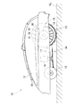
図1及び図2を参照して、無人走行作業車10の全体の構成の例を説明する。以下、無人走行作業車10を、作業車10とも呼ぶ。図1には、作業車10の一例として、芝草を刈るように自主的に走行可能なロボット式芝刈機10が示されている。作業車10は、ハウジング11と、ハウジング11の前部に備えた左右の前輪12と、ハウジング11の後部に備えた左右の後輪13と、ハウジング11の中央の下部に備えた作業部14と、を含む。図1に示される例においては、作業部14の一例として、ロボット式芝刈機10の芝刈ブレード14が示されている。
<< 1. Configuration example of an unmanned traveling vehicle >>
With reference to FIG.1 and FIG.2, the example of the whole structure of the unmanned traveling working
作業車10は、左右の後輪13を個別に駆動する左右の走行用モータ15と、作業部14を駆動する作業部駆動用モータ16と、バッテリ17と、車輪速センサ18と、電子制御装置(ECU;Electronic Control Unit)31、角速度センサ32及び加速度センサ33を搭載する基板30と、をハウジング11内に備える。また、作業車10は、作業車10の外部を撮像可能なカメラ21をハウジング11上に有する。カメラ21は、例えば、CCD、CMOS等の撮像センサと、被写体の像を撮像センサの撮像面に形成する撮像レンズとを有し、デジタル形式の画像を生成することができる。
The
走行用モータ15、作業部駆動用モータ16、車輪速センサ18、ECU31、角速度センサ32、加速度センサ33及びカメラ21は、バッテリ17から電力が供給される。例えば、走行用モータ15、作業部駆動用モータ16、車輪速センサ18、角速度センサ32、加速度センサ33及びカメラ21は、ECU31を経由してバッテリ17から電力が供給されてもよい。
The traveling
ECU31は、車輪速センサ18、角速度センサ32、加速度センサ33及びカメラ21から信号(又はデータ)を受け取り、走行用モータ15と作業部駆動用モータ16との動作を制御する。また、ECU31は、左右の走行用モータ15を個別に制御することによって、作業車10の移動を制御することができる。
The
すなわち、図2に示されているように、左の走行用モータ15は左の後輪13を、右の走行用モータ15は右の後輪13を、個別に駆動する。例えば、左右の走行用モータ15の双方が等速で正転することによって、作業車10は前方向に直進走行(前進)をする。同様に、左右の走行用モータ15の双方が等速で逆転することによって、作業車10は後方向に直進走行(後進)をする。
That is, as shown in FIG. 2, the
また、左側の走行用モータ15と右側の走行用モータ15とが異なる速度で正転することによって、作業車10は左右の走行用モータ15の回転速度の遅い側の方向に、旋回する。さらに、左右の走行用モータ15の一方が正転すると共に他方が同じ回転速度で逆転することによって、作業車10は、作業車10の位置が変わることなく、左右の走行用モータ15の逆転している側の方向に旋回可能である。
Further, when the
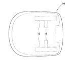
図3を参照して、基板30及び基板30に接続される装置等の構成の例を説明する。図3に示されているように、基板30は、ECU31と、角速度センサ32と、加速度センサ33と、左右の走行用モータ15の回転を個別に制御するドライバ36と、作業部駆動用モータ16の回転を制御するドライバ37と、を備える。また、基板30は、カメラ21、バッテリ17及び車輪速センサ18と電気的に接続されている。
With reference to FIG. 3, an example of the configuration of the
角速度センサ32は、作業車10の図示されていない重心位置の鉛直軸回りの回転角速度であるヨーレートを表す信号をECU31に対して出力する。すなわち、ECU31は、角速度センサ32からヨーレートを表す信号を受け取ることによって、作業車10の正面方向(進行方向)を演算等して取得することができる。
The
加速度センサ33は、作業車10の例えば前後方向、左右方向及び上下方向の3方向に作用する加速度を表す信号をECU31に対して出力する。加速度センサ33は、必ずしも3方向に作用する加速度を表す信号を出力する必要はなく、例えば上記3方向のうちの1方向又は2方向に作用する加速度を表す信号を出力してもよい。
The
ドライバ36は、ECU31から受け取る信号に応じて、左右の走行用モータ15の回転を個別に制御する。ドライバ37は、ECU31から受け取る信号に応じて、作業部駆動用モータ16の回転を制御する。ここで、図3に示される例においては、角速度センサ32、加速度センサ33、ドライバ36及びドライバ37は、ECU31とは別の構成要素として基板30上に備えられているが、例えば、これらの少なくとも1つ以上をECU31が備えてもよい。
The
車輪速センサ18は、後輪13の回転速度を検出可能に作業車10に備えられており、後輪13の回転速度を表す信号を基板30、具体的にはECU31に対して出力する。すなわち、ECU31は、車輪速センサ18から後輪13の回転速度を表す信号を受け取ることによって、作業車10が移動した距離を演算等して取得することができる。
The
カメラ21は、作業車10の外部を撮像可能に作業車10に備えられており、撮像した画像のデータを基板30、具体的にはECU31に対して出力する。ここで、図3に示される例においては、1つのカメラ21が基板30と電気的に接続されているが、2以上のカメラ21が基板30に接続されていてもよい。
The
また、作業車10の外部を周囲全体にわたって撮像可能に、適切な個数のカメラ21が作業車10の適切な位置に備えられていることが好ましい。例えば、作業車10のハウジング11の前側と後側と左側と右側とに1つずつ、合計4つのカメラ21が備えられることが好ましい。代替的に、例えば、作業車10の外部を周囲全体にわたって撮像可能な画角を有する1つのカメラ21が、作業車10のハウジング11の上位部に備えられてもよい。
In addition, it is preferable that an appropriate number of
図4を参照して、ECU31の構成の例を説明する。ECU31は、例えば、CPU(Central Processing Unit)等の処理部40と、RAM(Random Access Memory)、ROM(Read Only Memory)等の記憶部50と、を含むマイクロコンピュータで構成される。記憶部50には、作業車10が作業を行う範囲である作業エリアに関するマップデータ(マップ)51が記憶されている。
An example of the configuration of the
処理部40は、例えば、記憶部50に記憶されている図示されていないプログラムを実行することによって、移動方向決定部41、画像解析部43、挙動取得部44及び測量部45として機能する。代替的に、移動方向決定部41、画像解析部43、挙動取得部44及び測量部45の少なくとも1つは、例えばアナログ回路等のハードウェアで実現されてもよい。
The
移動方向決定部41は、作業車10が移動する方向(移動方向)を決定する。画像解析部43は、カメラ21が作業車10の外部を撮像した画像を受け取り、例えば、公知の画像処理、パターンマッチング手法等を用いて画像を解析する。作業車10が複数のカメラ21を備えるときは、画像解析部43は、例えば、複数のカメラ21から受け取る作業車10の外部を撮像した画像を結合して得られる、作業車10の周囲全体にわたる画像を解析してもよい。画像解析部43は、受け取った画像に後述する標識が含まれているときには、標識を抽出する。そして、画像解析部43は、作業車10の正面方向(進行方向)と、作業車10の現在位置から抽出した標識を指す方向との角度差を演算等することによって取得する。
The movement
挙動取得部44は、作業車10が移動した距離及び方向を含む挙動情報を取得する。挙動取得部44は、車輪速センサ18から受け取る信号に応じて作業車10が移動した距離を演算等して取得する。また、挙動取得部44は、角速度センサ32から受け取る信号に応じて作業車10が移動した方向を演算等して取得する。挙動取得部44は、例えば、加速度センサ33から受け取る信号に応じて演算等して取得した情報を、さらに挙動情報に含んでもよい。
The behavior acquisition unit 44 acquires behavior information including the distance and direction that the
測量部45は、画像解析部43による解析結果及び挙動取得部44による挙動情報を用いて、画像解析部43が抽出した標識の位置情報を後述する三角測量法によって取得する。測量部45は、例えば、取得した標識の位置情報を、マップ51に反映させる。
The surveying
作業車10は、作業車10の動作モードとして、例えば、作業モードと測量モードとを有している。作業車10は、作業モードで動作するときは、作業エリア内を自主的に走行し、例えば芝草を刈る等の作業を行う。また、作業車10は、測量モードで動作するときは、自主的に走行している間に標識の位置情報を取得してマップ51を更新する。
The
《2.無人走行作業車の動作の例》
《2−1.作業エリアと無人走行作業車の動作との関係》
図5を参照して、作業エリア70と作業車10の動作との関係について説明する。図5には、作業エリア70を上から見た例が示されている。図5に示されている例では、作業エリア70が破線で囲まれた範囲として示されている。また、図5に示されている例では、作業車10を収容可能なステーション60が示されている。作業車10は、ステーション60に収容されることによってバッテリ17の充電が可能となる。また、作業車10は、作業モード又は測量モードでの動作を終えたときに、ステーション60まで移動して収容されてもよい。なお、図5に示されている例においては、ステーション60は作業エリア70の内側と外側とをまたがっているような状態で配置されているが、ステーション60は、作業エリア70の内側に配置されていてもよく、作業エリア70の外側に配置されていてもよい。
<< 2. Example of operation of an unmanned traveling vehicle >>
<< 2-1. Relationship between work area and operation of unmanned work vehicle >>
The relationship between the
作業車10は、ECU31の記憶部50が記憶しているマップ51上に作業エリア70を設定(又は記憶)することができる。マップ51は、例えば、地面と同一平面を表す二次元マップであり、マップ51上の位置情報(二次元座標)と実空間上の位置情報(二次元座標)とは対応関係にある。実空間上の位置情報(二次元座標)は、例えば、地面と同一平面上の座標平面で表され、この座標平面は、ステーション60が配置されている位置又は予め設定された位置を原点としてX軸及びX軸と直角に交差するY軸の2つの座標軸で構成される。なお、図5に示される例においては、原点、X軸及びY軸の図示が省略されており、X軸正方向及びY軸正方向の例が表されている。
The
図5に示されている例では、長方形の作業エリア70が示されており、この長方形の4つの頂点には標識71(71−1,71−2,71−3,71−4)が存在している。すなわち、図5に示されている例においては、マップ51上では、実空間上で4つの標識71(71−1,71−2,71−3,71−4)の位置に対応する4つの座標点によって規定される長方形の内側の範囲が作業エリア70として設定されている。
In the example shown in FIG. 5, a
作業車10は、上述したように、ECU31の挙動取得部44によって、作業車10が移動した距離及び作業車10が移動した方向を含む挙動情報を取得することができる。そのため、作業車10は、マップ51上において、作業車10の現在位置を把握することができる。
As described above, the
このように、作業車10は、マップ51上に作業エリア70を設定した後は、作業エリア70の内側のみを走行することができる。その結果、作業車10は、例えば、作業モードで動作するときに、作業エリア70の内側のみを自主的に走行し、芝草を刈る等の作業を行うことが実現できる。
Thus, after setting the
マップ51上で作業エリア70を設定するためには、実空間上の作業エリア70の内側と外側との境界に関する位置情報(二次元座標)を把握する必要がある。作業車10では、測量部45が、実空間上の作業エリア70の内側と外側との境界に関する位置情報として、実空間上の標識71の位置情報(二次元座標)を三角測量法によって取得する。なお、ユーザーはマップ51を編集可能であり、例えば、マップ51上に反映された標識71の位置情報から任意の距離だけ離れた位置を作業エリア70の内側と外側との境界に設定してもよい。
In order to set the
また、標識71は、画像解析部43がカメラ21から受け取った画像から抽出可能な物であり、例えば地面に自立可能な棒状の物であってもよい。また、画像解析部43がカメラ21から受け取った画像から抽出可能である限り、木、石等が標識71として使用されてもよい。さらに、標識71は、例えば、カメラ21が撮像対象とする特定の周波数領域の光を発光可能に構成されていてもよい。
The
《2−2.三角測量法による標識の位置情報の取得》
図6を参照して、測量部45が三角測量法を用いて、標識71の位置情報(二次元座標)を取得する方法の一例を説明する。図6には、一定方向に移動する作業車10と、標識71とを上から見た例が示されている。
<< 2-2. Acquisition of location information of sign by triangulation method >>
With reference to FIG. 6, an example of a method in which the
作業車10が一定方向に移動するときに通る、位置10−Aと位置10−Bとの距離をLとする。位置10−Aと標識71の位置とを結ぶ直線の距離をHAとする。位置10−Aと標識71の位置とを結ぶ直線と、作業車10が移動した方向と、がなす角をθAとする。位置10−Bと標識71の位置とを結ぶ直線と、作業車10が移動した方向と、がなす角をθBとする。位置10−Aと標識71の位置とを通る直線と、位置10−Bと標識71の位置とを通る直線と、がなす角をθαとする。このとき、正弦定理から次の式(1)が得られる。
HA/sin(π−θB)=L/sinθα
HA/sinθB=L/sin(θB−θA) (1)
(∵ sin(π−θB)=sinθB, θα=θB−θA)
Let L be the distance between position 10-A and position 10-B through which work
HA / sin (π−θB) = L / sin θα
HA / sin θB = L / sin (θB−θA) (1)
(∵ sin (π−θB) = sin θB, θα = θB−θA)
また、式(1)を変形することによって、次の式(2)が得られる。
HA=L・sinθB/sin(θB−θA) (2)
Further, the following equation (2) is obtained by modifying the equation (1).
HA = L · sin θB / sin (θB−θA) (2)
このように、LとθAとθBとを得ることによって、式(2)を演算してHAを決定することができる。ここで、測量部45は、作業車10が位置10−Aから位置10−Bまで一定方向に移動することによって、LとθAとθBとを得ることができる。すなわち、Lは挙動取得部44が取得し、θAとθBとは画像解析部43が取得する。したがって、測量部45は、標識71が、位置10−Aにおいて作業車10の正面方向(進行方向)との角度差がθAの方向であって、位置10−AからHAだけ離れた位置に配置されていることを取得することができる。以上のように、測量部45は、三角測量法を用いて、標識71の位置情報(二次元座標)を取得する。
Thus, by obtaining L, θA, and θB, HA can be determined by calculating equation (2). Here, the surveying
以下、測量部45が三角測量法を用いて標識71の位置情報を取得するときに、作業車10が一定の移動方向に移動する間に通る2つの位置(図6において位置10−A及び位置10−Bに相当)のうち、一方を第1地点(図6において位置10−Aに相当)とも呼び、他方を第2地点(図6において位置10−Bに相当)とも呼ぶ。また、第1地点から標識71を指す方向と移動方向との角度差を第1角度(図6において角度θAに相当)とも呼び、第2地点から標識71を指す方向と移動方向との角度差を第2角度(図6において角度θBに相当)とも呼ぶ。
Hereinafter, when the surveying
《2−3.測量モードにおける無人走行作業車の動作の例》
図7及び図8を参照して、測量モードにおける作業車10の動作の例を説明する。図7には、作業車10と4つの標識71(71−1,71−2,71−3,71−4)とを上から見た例が示されている。図7に示される例おいて、作業車10は位置10−1で測量モードの実行を開始したとする。
<< 2-3. Example of operation of unmanned work vehicle in survey mode >>
With reference to FIG.7 and FIG.8, the example of operation | movement of the working
測量モードの実行を開始した作業車10は、位置10−1で作業車10の外部をカメラ21によって撮像する。画像解析部43は、カメラ21が撮像した画像を受け取って解析する。画像解析部43は、解析した画像に標識71−1が含まれているときに、標識71−1を抽出する。測量部45は、画像解析部43が抽出した標識71−1の位置情報の取得を開始する。
The
移動方向決定部41は、測量部45が位置情報の取得を開始する標識71−1について、位置情報を取得するために作業車10が移動する移動方向を決定する。すなわち、移動方向決定部41は、作業車10が標識71(標識71−1)と接触しない方向であって、且つ、作業車10の現在位置(位置10−1)から標識71(標識71−1)を指す方向との角度差θg(θg1)が90degよりも小さくなる方向を、作業車10の移動方向として決定する。
The movement
移動方向決定部41によって作業車10の移動方向が決定されると、作業車10は正面方向(進行方向)と移動方向決定部41が決定した移動方向とが一致するまで旋回する。正面方向(進行方向)と移動方向決定部41が決定した移動方向とが一致した後に、作業車10が正面方向(進行方向)に移動(前進)する。作業車10が移動している間に、測量部45が上述した三角測量法によって標識71(標識71−1)の位置情報を取得する。
When the movement direction of the
以上のように、測量部45が標識71の位置情報の取得を開始するときに、移動方向決定部41が作業車10の移動方向を決定することによって、ユーザーが標識71の位置情報を自身で取得すること及び作業車10の移動方向を案内することなく、標識71の位置情報を取得することができる。また、移動方向決定部41が決定する移動方向が、作業車10が標識71と接触しない方向であって、且つ、作業車10の現在位置から標識71を指す方向との角度差θgが90degよりも小さくなる方向であることによって、作業車10が決定された移動方向に移動している間に、作業車10と標識71との距離が近づくタイミングが発生する。すなわち、作業車10と標識71との距離が近づくタイミングが発生しない、作業車10の現在位置から標識71を指す方向との角度差θgが90deg以上となる方向に作業車10が移動する場合と比較して、標識71との距離が近いときに撮像された画像に基づいて標識71の位置情報を取得することができる。
As described above, when the surveying
移動方向決定部41が決定する移動方向は、作業車10が標識71と接触しない方向であって、且つ、作業車10の現在位置から標識71を指す方向との角度差θgが45degよりも小さくなる方向であることが好ましい。この場合、作業車10が決定された移動方向に移動している間に、作業車10と標識71との距離が近づくタイミングが十分に発生する。
The movement direction determined by the movement
また、測量部45は、画像解析部43が抽出した標識71(71−1)の位置情報の取得が完了しているか否かを判定してもよい。そして、標識71(71−1)の位置情報の取得が完了していないと判定したときに、測量部45は標識71(71−1)の位置情報の取得を開始してもよい。例えば、測量部45は、マップ51を参照して、位置情報が記憶されている標識71を、位置情報の取得が完了した標識71と判定してもよい。代替的に、測量部45は、位置情報の取得が所定の回数実行された標識71を、位置情報の取得が完了した標識71と判定してもよい。
Further, the surveying
測量部45が、位置情報の取得が完了していない標識71の位置情報の取得を開始することによって、すでに位置情報の取得が完了している標識71について、再度位置情報の取得を実行されることを防ぐことができる。その結果、例えば、測量モードにおける動作にかかるバッテリ17の電力消費を軽減することができる。
The surveying
また、画像解析部43は、受け取った画像に複数の標識71が含まれているときには、これら全ての標識71を抽出する。測量部45は、画像解析部43が抽出した複数の標識71のなかに位置情報の取得が完了していない標識71が含まれているか判定する。位置情報の取得が完了していない標識71が含まれているときは、測量部45は、位置情報の取得が完了していない標識71のうち作業車10の現在位置からの視認性の最も良い標識71の位置情報の取得を開始する。作業車10の現在位置からの視認性の最も良い標識71とは、例えば、受け取った画像上での大きさが最も大きい標識71であってもよい。例えば、標識71の位置情報の取得が完了した位置でカメラ21が撮像する画像に、位置情報の取得が完了していない標識71が含まれなくなるまで、同様の手順が繰り返される。
Further, when the received image includes a plurality of
具体的に、図7に示される例において、作業車10が位置10−1のときにカメラ21が撮像する画像に位置情報の取得が完了していない4つの標識71(71−1,71−2,71−3,71−4)が含まれたとする。このとき、画像解析部43は受け取った画像に含まれる4つの標識71(71−1,71−2,71−3,71−4)を抽出し、測量部45は4つの標識71(71−1,71−2,71−3,71−4)の位置情報の取得が完了していないと判定する。測量部45は、位置情報の取得が完了していない4つの標識71(71−1,71−2,71−3,71−4)のうち作業車10の現在位置(位置10−1)からの視認性の最も良い標識71−1の位置情報の取得を開始する。そして、移動方向決定部41によって作業車10の移動方向が決定され、決定された移動方向に作業車10が移動している間に測量部45が標識71−1の位置情報を取得する。
Specifically, in the example shown in FIG. 7, when the
その後、標識71−1の位置情報の取得が完了した位置(例えば位置10−2)でカメラ21が撮像する画像に、4つの標識71(71−1,71−2,71−3,71−4)が含まれたとする。このとき、画像解析部43は受け取った画像に含まれる4つの標識71(71−1,71−2,71−3,71−4)を抽出し、測量部45は3つの標識71(71−2,71−3,71−4)の位置情報の取得が完了していないと判定する。測量部45は、位置情報の取得が完了していない3つの標識71(71−2,71−3,71−4)のうち作業車10の現在位置(位置10−2)からの視認性の最も良い標識71−2の位置情報の取得を開始する。
Thereafter, four signs 71 (71-1, 71-2, 71-3, 71- are displayed on the image captured by the
標識71−2の位置情報の取得が完了した位置(例えば位置10−3)において同様の手順によって標識71−3の位置情報の取得が開始され、さらに標識71−3の位置情報の取得が完了した位置(例えば位置10−4)において同様の手順によって標識71−4の位置情報の取得が開始される。ここで、いずれの標識71の位置情報の取得が開始されるときも、移動方向決定部41が決定する移動方向は、作業車10が標識71と接触しない方向であって、且つ、作業車10の現在位置から標識71を指す方向との角度差θg(θg1,θg2,θg3,θg4)が90degよりも小さくなる方向である。
The acquisition of the position information of the sign 71-3 is started by the same procedure at the position where the acquisition of the position information of the sign 71-2 is completed (for example, the position 10-3), and the acquisition of the position information of the sign 71-3 is further completed. The acquisition of the position information of the marker 71-4 is started by the same procedure at the position (for example, the position 10-4). Here, when the acquisition of the position information of any
標識71−4の位置情報の取得が完了した位置(図示されていない)でカメラ21が撮像する画像に、位置情報の取得が完了していない標識71が含まれていない(全ての標識71の位置情報の取得が完了した)と測量部45が判定すると、作業車10は測量モードでの動作を終了してもよい。しかしながら、代替的に、例えば、全ての標識71の位置情報の取得が3回完了されたときに、作業車10が測量モードでの動作を終了してもよい。
The image captured by the
このように、カメラ21が撮像した画像に複数の標識71が含まれるときに、測量部45が位置情報の取得する標識71を決定することによって、ユーザーが位置情報の取得する標識71を決定する必要がない。また、測量部45は、位置情報の取得が完了していない標識71のなかから作業車10の現在位置からの視認性の最も良い標識71の位置情報の取得を開始することによって、例えば現在位置からの距離が最も遠い標識71の位置情報の取得を開始する場合と比較して、全ての標識71の位置情報の取得が完了するまでに必要とする移動距離が短くなる。その結果、測量モードにおける動作にかかるバッテリ17の電力消費を軽減することができる。
As described above, when a plurality of
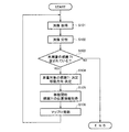
図8に示されるフローチャートを参照して、測量モードにおける作業車10の動作の一連の流れの例を説明する。ステップS101では、作業車10のカメラ21が作業車10の外部を撮像する。ステップS102では、画像解析部43が、カメラ21が撮像した画像を分析し、画像に含まれる標識71を抽出する。ステップS103では、測量部45が、画像解析部43が抽出した標識71のなかに位置情報の取得が完了していない標識71が含まれているか否かを判定する。
With reference to the flowchart shown in FIG. 8, an example of a series of flows of the operation of the
ステップS103の判定がYESのときにフローはステップS104に進み、ステップS103の判定がNOのときにフローは終了する。ステップS104では、測量部45が位置情報を取得する標識71を決定し、移動方向決定部41が作業車10の移動方向を決定する。ステップS105では、作業車10は移動方向決定部41が決定した移動方向に移動を開始し、作業車10がこの移動方向に移動している間に測量部45が標識71の位置情報を上述した三角測量法によって取得する。
When the determination in step S103 is YES, the flow proceeds to step S104, and when the determination in step S103 is NO, the flow ends. In step S <b> 104, the surveying
ステップS106では、測量部45は、取得した標識71の位置情報をマップ51に反映させて、マップ51を更新する。マップ51の更新が終了すると、フローは再度ステップS101に進む。すなわち、ステップS103のステップで、画像解析部43が抽出した標識71のなかに位置情報の取得が完了していない標識71が含まれていないと判定されるまで、ステップS101からステップS106の処理が繰り返される。
In step S <b> 106, the surveying
《2−4.位置情報の取得の精度》
図9、図10及び図11を参照して、測量部45による標識71の位置情報の取得の精度について説明する。図9には、作業車10と標識71とを上から見た例が示されている。また、図9に示される例においては、作業車10と標識71とは距離Hだけ離れている。
<< 2-4. Accuracy of location information acquisition >>
With reference to FIG. 9, FIG. 10, and FIG. 11, the accuracy of acquisition of the position information of the
ここで、一般的にデジタル形式の画像を生成可能なカメラでは、被写体の像を撮像センサの撮像面に形成するときに、撮像センサの分解能、撮像レンズの焦点距離等に起因した誤差が生じる。この誤差が影響して、カメラ21が撮像するときに所定の角度の撮像誤差±θp(撮像誤差の範囲は2θp)が生じる。撮像誤差±θpが生じることによって、作業車10から距離Hだけ離れる標識71は、実空間上の2Htanθpの範囲の誤差を含んだ状態で撮像される。すなわち、カメラ21と標識71との距離が遠くなることに応じて撮像誤差の影響が大きくなる。
Here, in a camera that can generally generate a digital image, an error due to the resolution of the imaging sensor, the focal length of the imaging lens, and the like occurs when an image of a subject is formed on the imaging surface of the imaging sensor. Due to this error, when the
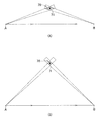
図10及び図11を参照して、三角測量法による標識71の位置情報の取得における撮像誤差の影響を説明する。図10の(A)及び(B)に示される領域76は、三角測量法を用いて標識71の位置情報が取得される誤差の範囲を表す。領域76は、第1地点の例である位置Aで標識71を撮像するときの撮像誤差と、第2地点の例である位置Bで標識71を撮像するときの撮像誤差と、が重なって形成される領域である。
With reference to FIG. 10 and FIG. 11, the influence of the imaging error in the acquisition of the position information of the
図10に示される(A)の例と(B)の例と間で、位置A(第1地点)と標識71との距離及び位置B(第2地点)と標識71との距離は概ね同じである。しかしながら、位置A(第1地点)、標識71、位置B(第2地点)からなる角度が図10の(A)に示される例よりも90[deg]に近い図10の(B)の方が、領域76が小さくなっている。なお、位置A(第1地点)、標識71、位置B(第2地点)からなる角度は、第1角度と第2角度との角度差と同じである。
The distance between the position A (first point) and the
このように、撮像誤差を考慮すると、三角測量法に用いる第1角度と第2角度との角度差が90[deg]に近い程、標識71の位置情報の取得の精度が向上する。すなわち、測量部45は、作業車10が移動方向に移動している間に、第1角度と第2角度との角度差が90[deg]に近づくように、第1地点及び/又は第2地点を決定することによって、撮像誤差を軽減することができる。その結果、ユーザーが、標識71の位置情報の取得の精度を担保するために、第1地点及び第2地点を決定する必要がない。
As described above, in consideration of the imaging error, the accuracy of obtaining the position information of the
また、図11には、第1角度と第2角度との角度差が略90[deg]であるときの三角測量法を用いた標識71の位置情報の取得の精度を表す2つの例として、図11の(A)及び(B)が示されている。図11の(A)の領域76と(B)の領域76とでは、図11の(A)の方が大きくなっている。これは、図11の(A)における位置A(第1地点)と標識71との距離が図11の(B)のにおける位置A(第1地点)と標識71との距離よりも長くなっていることにより、撮像誤差が大きく影響しているためである。
Moreover, in FIG. 11, as two examples showing the acquisition accuracy of the position information of the
第1角度と第2角度との角度差が略90[deg]であるときに、第1地点と標識71との距離及び第2地点と標識71との距離の双方が最も短くなる条件は、図11の(B)に示されるように第1角度θAが略45[deg]及び第2角度θBが略135[deg]が成立するときである。すなわち、測量部45は、作業車10が移動方向に移動している間に、第1角度が45[deg]に近づくように第1地点を決定すると共に、第2角度が135[deg]に近づくように第2地点を決定することによって、標識71の位置情報の取得の精度が向上する。
When the angle difference between the first angle and the second angle is approximately 90 [deg], the condition that both the distance between the first point and the
ここで、標識71の位置情報の取得の精度の観点からも、測量部45が標識71の位置情報の取得を開始するときに移動方向決定部41が決定する移動方向は、作業車10が標識71と接触しない方向であって、且つ、作業車10の現在位置から標識71を指す方向との角度差θgが45degよりも小さくなる方向であることが好ましい。すなわち、作業車10の移動方向が作業車10の現在位置から標識71を指す方向との角度差θgが45degよりも小さくなる方向であるときには、作業車10が移動している間に、第1角度が45[deg]となる第1地点を必ず通る。
Here, also from the viewpoint of the accuracy of the acquisition of the position information of the
《2−5.標識の位置情報の取得に係る処理》
図12に示されるフローチャートを参照して、測量部45が標識71の位置情報の取得するときの詳細の処理の例を説明する。図12に示されるフローチャートは、図8に示されるフローチャートにおけるステップS105の詳細な処理の例である。
<< 2-5. Processing related to acquisition of sign position information >>
An example of detailed processing when the surveying
ステップS201では、測量部45は、標識71検出フラグがONであるか否かを判定する。ステップS201の判定がYESのときにフローはステップS205に進み、ステップS201の判定がNOのときにフローはステップS202に進む。なお、図8に示されるフローチャートにおけるステップS104からステップS105に進んだ直後は、標識71検出フラグはOFFである。
In step S201, the surveying
ステップS202では、測量部45は、現在位置でカメラ21が撮像した画像に標識71が含まれているか否かを判定する。ステップS202の判定がYESのときにフローはステップS203に進み、ステップS202の判定がNOのときにフローはSTARTに戻る。
In step S202, the surveying
ステップS203では、測量部45は、ステップS202で判定した画像を撮像した位置における作業車10の移動方向と作業車10から標識71を指す方向との角度差を、第1角度として記憶する。以下、画像を撮像した位置における作業車10の移動方向と作業車10から標識71を指す方向との角度差を、標識71検出角度とも呼ぶ。測量部45は、例えば、標識71検出角度を画像解析部43から受け取る。また、ステップS203では、測量部45は、ステップS202で判定した画像を撮像した位置を第1地点として記憶する。以下、画像を撮像した位置を、標識71検出位置とも呼ぶ。測量部45は、例えば、標識71検出位置を挙動取得部44から受け取る。
In step S203, the surveying
ステップS204では、測量部45は、標識71検出フラグをONにする。ステップS204の処理が終了すると、フローはSTARTへ戻る。ステップS205では、測量部45は、第1角度が確定されているか否かを判定する。ステップS205の判定がYESのときにフローはステップS211に進み、ステップS205の判定がNOのときにフローはステップS206に進む。
In step S204, the surveying
ステップS206では、現在位置でカメラ21が撮像した画像に標識71が含まれているか否かを判定する。ステップS206の判定がYESのときにフローはステップS207に進み、ステップS206の判定がNOのときにフローは終了する。なお、ステップS206の判定がNOでフローは終了するときは、検出できていた標識71が何かしらの原因で検出できない(画像解析部43が標識71を抽出できない)状況が発生しているため、例えば、図8のフローチャートのステップS101に戻る。
In step S206, it is determined whether or not the
ステップS207では、ステップS206で判定した画像を撮像した位置における標識71検出角度が、第1角度よりも45[deg]に近いか否かを判定する。ステップS207の判定がYESのときにフローはステップS208に進み、ステップS207の判定がNOのときにフローはステップS209に進む。
In step S207, it is determined whether the
ステップS208では、測量部45は、現在記憶されている第1角度に代えて、ステップS206で判定した画像を撮像した位置における標識71検出角度を新たに第1角度として記憶(上書き)する。また、ステップS208では、測量部45は、現在記憶されている第1地点に代えて、ステップS206で判定した画像を撮像した位置を新たに第1地点として記憶(上書き)する。
In step S208, the surveying
ステップS209では、測量部45は、現在記憶されている第1角度及び現在記憶されている第1地点を、三角測量法に用いる第1角度及び第1地点として確定する。ステップS210では、測量部45は、ステップS206で判定した画像を撮像した位置における標識71検出角度を第2角度として記憶し、画像を撮像した位置を第2地点として記憶する。ステップS208又はステップS210の処理が終了すると、フローはSTARTへ戻る。
In step S209, the surveying
測量部45は、ステップS207、ステップS208、ステップS209の処理を有することによって、作業車10が移動方向に移動している間に、第1角度が45[deg]に近づくように第1地点を決定することができる。その結果、標識71の位置情報の取得の精度が向上する。
The surveying
ステップS211では、現在位置でカメラ21が撮像した画像に標識71が含まれているか否かを判定する。ステップS211の判定がYESのときにフローはステップS212に進み、ステップS211の判定がNOのときにフローはステップS214に進む。
In step S211, it is determined whether or not the
ステップS212では、ステップS211で判定した画像を撮像した位置における標識71検出角度と確定された第1角度との角度差が、現在記憶されている第2角度と確定された第1角度との角度差よりも、90[deg]に近いか否かを判定する。ステップS212の判定がYESのときにフローはステップS213に進み、ステップS212の判定がNOのときにフローはステップS214に進む。
In step S212, the difference between the detected angle of the
ステップS213では、測量部45は、現在記憶されている第2角度に代えて、ステップS211で判定した画像を撮像した位置における標識71検出角度を新たに第2角度として記憶する。また、ステップS213では、測量部45は、現在記憶されている第2地点に代えて、ステップS211で判定した画像を撮像した位置を新たに第2地点として記憶する。ステップS213の処理が終了すると、フローはSTARTへ戻る。
In step S213, the surveying
ステップS214では、測量部45は、現在記憶されている第2角度及び現在記憶されている第2地点を、三角測量法に用いる第2角度及び第2地点として確定する。ステップS215では、測量部45は、確定された第1角度、確定された第2角度、確定された第1地点と確定された第2地点との距離を用いて、三角測量法によって標識71の位置情報を演算して取得する。ステップS215の処理が終了すると、フローは終了する。すなわち、ステップS215の処理が終了すると、図8に示されるフローチャートのステップS106に進む。
In step S214, the surveying
測量部45は、ステップS212、ステップS213、ステップS214の処理を有することによって、作業車10が移動方向に移動している間に、第2角度が135[deg]に近づくように第2地点を決定することができる。その結果、標識71の位置情報の取得の精度が向上する。
The surveying
図12に示されているフローチャートは一例であって、測量部45は、全てのステップの処理を実行する必要はない。測量部45は、例えば、第1地点を確定するための処理、すなわち、図12に示されているフローチャートのステップS201からステップS209までに相当する処理を、実行してもよい。また、測量部45は、例えば、第2地点を確定するための処理、すなわち、図12に示されているフローチャートのステップS211からステップS215までに相当する処理を、実行してもよい。
The flowchart shown in FIG. 12 is an example, and the surveying
《2−6.特別な場合における動作》
図13及び図14を参照して、特別な場合の例として、作業車10が移動している間に、画像解析部43が、カメラ21が撮像する画像から抽出できていた標識71を、カメラ21が撮像する画像から抽出できない状況が発生したときの動作の例を説明する。以下、この「画像解析部43が、カメラ21が撮像する画像から抽出できていた標識71を、カメラ21が撮像する画像から抽出できない状況」を、ロストとも呼ぶ。ロストは、例えば、位置が固定されている木、岩等又は位置が固定されていない人、動物等が障害物78となってカメラ21と標識71との間を遮るときに発生し得る。また、ロストは、例えば、逆光等によっても発生し得る。
<< 2-6. Action in special cases >>
Referring to FIGS. 13 and 14, as an example of a special case, the
図13には、一定の移動方向に移動する作業車10と標識71とを上から見た例が示されている。また、図13には、障害物78が示されている。図13に示されているように、位置10−A、位置10−B、位置10−E及び位置10−Fからは、障害物78と干渉することなく、作業車10と標識71とを直線でつなぐことができる。その一方で、図13に示されているように、位置10−C及び10−Dからは、障害物78と干渉することなく、作業車10と標識71とを直線でつなぐことができない。
FIG. 13 shows an example in which the
すなわち、例えば作業車10がカメラ21で外部を撮像しながら図13に示される移動方向に移動する間に、位置10−A及び位置10−Bにおいて撮像する画像から画像解析部43が抽出していた標識71を、位置10−Cにおいて撮像する画像から画像解析部43が抽出できなくなる状況(ロスト)が発生する。その後、位置10−Eまで作業車10が移動したときに、撮像する画像から画像解析部43が再度標識71を抽出可能になり、ロストが解消される。
That is, for example, while the
例えば、何かしらの対策もなされないとすると、画像解析部43は、ロスト発生前に抽出した標識71と、ロスト解消後に抽出する標識71とを異なる標識71として認識することが想定される。例えば、測量部45が標識71の位置情報を取得するために作業車10が移動している間に、このようなロストが発生したとすると、測量部45が標識71の位置情報を精度良く取得できないこと又は標識71の位置情報を取得することができないことが想定される。すなわち、測量部45が標識71の位置情報を取得するための情報は、作業車10が位置10−Cに到達するまで(ロスト発生前)に得た情報(標識71検出角度及び標識71検出位置)又は、作業車10が位置10−Eに到達した後(ロスト解消後)に得た情報(標識71検出角度及び標識71検出位置)のいずれか一方に限られることが想定される。
For example, if no countermeasure is taken, it is assumed that the
例えば、図12に示されるフローチャートに従うと、ステップS211の判定でNO又はステップS206の判定でNOとなる。例えばステップS211の判定でNOとなるときは、作業車10が位置10−Cまで移動する間に記憶された第2角度及び第2地点が三角測量法に用いる第2角度及び第2地点として確定され(ステップS214)、すでに確定している第1角度及び第1地点とともに三角測量法によって標識71の位置情報が取得される(ステップS215)。この場合には、標識71の位置情報を精度良く取得できない可能性がある。また、例えばステップS206の判定でNOとなるときは、標識71の位置情報が取得されることなくフローが終了する。
For example, according to the flowchart shown in FIG. 12, the determination in step S211 is NO or the determination in step S206 is NO. For example, when the determination in step S211 is NO, the second angle and the second point stored while the
ここで、図13に示されている例では、位置10−Eまで作業車10が移動したときに、撮像する画像から画像解析部43が再度標識71を抽出可能になるため、画像解析部43は、ロスト発生前に抽出していた標識71とロスト解消後に抽出する標識71とが同一の標識71であるか否かを判定してもよい。画像解析部43がロスト発生前に抽出していた標識71とロスト解消後に抽出する標識71とが同一の標識71であるときは、測量部45は、ロスト発生前に得た情報(標識71検出角度及び標識71検出位置)と、ロスト解消後に得た情報(標識71検出角度及び標識71検出位置)との双方を用いて標識71の位置情報を取得してもよい。
Here, in the example illustrated in FIG. 13, when the
そうすると、測量部45が、例えば、ロスト発生前に得た情報又は、ロスト解消後に得た情報の一方のみを用いて標識71の位置情報を取得する場合と比較して、標識71の位置情報を精度良く取得することができる。また、例えば、ユーザーが、作業車10が移動する間に障害物78の影響がない位置まで作業車10を案内する必要がない。
Then, compared with the case where the surveying
図14を参照して、ロストが発生した後に解消したときに、画像解析部43が、ロスト解消後に抽出する標識71と、ロスト発生前に抽出していた標識71とが同一の標識71であるか否かを判定する方法の例を説明する。
Referring to FIG. 14, when the loss is resolved after the occurrence of the lost, the
図14の(A)は、ロスト発生前にカメラ21が撮像した画像の例として、図13の例の位置10−Bで撮像された画像80Bを示す。図14の(B)は、ロスト解消後にカメラ21が撮像した画像の例として、図13の例の位置10−Eで撮像された画像89Eを示す。図14の(C)は、画像解析部43が画像80Bのなかから標識71以外を取り除く画像処理を施した画像の例として、加工画像80Biを示す。図14の(D)は、画像解析部43が画像80Eのなかから標識71以外を取り除く画像処理を施した画像の例として、加工画像80Eiを示す。なお、図14では、障害物78の図示を省略している。
FIG. 14A shows an
1つの方法の例として、画像解析部43は、画像80B上における標識71の近傍の風景の形状特徴と、画像80E上における標識71の近傍の風景の形状特徴とを比較してもよい。画像解析部43は、この比較結果に応じて、画像80Bに含まれる標識71と画像80Eに含まれる標識71とが同一の標識71であるか否かを判定してもよい。この方法の例によると、標識71の近傍の風景の形状特徴を判定に用いることができる。例えば、標識71の近傍の風景に特徴的なもの(例えば木等)が含まれている場合等に効果がある。また、例えば、ロスト解消後に撮像された画像に複数の同一形状の標識71が含まれている場合等、標識71の形状特徴のみで同一性を判定することが困難な場合にも判定の精度を担保する効果がある。
As an example of one method, the
他の方法の例として、画像解析部43は、図13の例の位置10−Bと図13の例の位置10−Eとの距離を用いて、画像80Bに含まれる標識71が画像80Eにおいて含まれる位置を予測して、予測された画像80E上での標識71の位置と、実際の画像80E上での標識71の位置とを比較してもよい。画像解析部43は、この比較結果に応じて、画像80Bに含まれる標識71と画像80Eに含まれる標識71とが同一の標識71であるか否かを判定してもよい。この方法の例によると、作業車10が移動した距離を判定に用いることができる。例えば、例えば、ロスト解消後に撮像された画像に複数の同一形状の標識71が含まれている場合等、標識71の形状特徴のみで同一性を判定することが困難な場合にも判定の精度を担保する効果がある。
As another example of the method, the
また、他の方法の例として、加工画像80Bi上における標識71の形状特徴と、加工画像80Ei上における標識71の形状特徴とを比較してもよい。画像解析部43は、この比較結果に応じて、画像80Bに含まれる標識71と画像80Eに含まれる標識71とが同一の標識71であるか否かを判定してもよい。この方法の例によると、標識71の形状特徴を判定に用いることができる。例えば、標識71の形状が特徴的な形状を有している場合等に特に効果がある。
As another example of the method, the shape feature of the
また、さらなる他の方法の例として、画像解析部43は、図13の例の位置10−Bと図13の例の位置10−Eとの距離を用いて、加工画像80Biに含まれる標識71が加工画像80Eiにおいて含まれる位置を予測して、予測された加工画像80Ei上での標識71の位置と、実際の加工画像80Ei上での標識71の位置とを比較してもよい。画像解析部43は、この比較結果に応じて、画像80Bに含まれる標識71と画像80Eに含まれる標識71とが同一の標識71であるか否かを判定してもよい。この方法の例によると、作業車10が移動した距離を判定に用いることができる。例えば、例えば、ロスト解消後に撮像された画像に複数の同一形状の標識71が含まれている場合等、標識71の形状特徴のみで同一性を判定することが困難な場合にも判定の精度を担保する効果がある。
As still another example of the method, the
ロストが発生した後に解消したときに、画像解析部43が、ロスト解消後に抽出する標識71と、ロスト発生前に抽出していた標識71とが同一の標識71であるか否かを判定する方法の例をいくつか挙げた。画像解析部43は、これらの方法の1つを単独で実行した結果を用いて判定してもよいし、これらの方法の2つ以上の方法を実行した結果を用いて総合的に判定してもよい。また、画像解析部43は、ここで挙げられていない他の方法を併せて実行して、その結果も考慮して総合的に判定してもよい。
A method of determining whether or not the
ここまで説明した作業車10の動作は、全てが実施される必要はない。すなわち、作業車10は、ここまで説明した動作の例のうちの一部を実施してもよい。
All the operations of the
本発明は、上述の例示的な実施形態に限定されず、また、当業者は、上述の例示的な実施形態を特許請求の範囲に含まれる範囲まで、容易に変更することができるであろう。 The present invention is not limited to the above-described exemplary embodiments, and those skilled in the art will be able to easily modify the above-described exemplary embodiments to the extent included in the claims. .
10・・・無人走行作業車、18・・・車輪速センサ、21・・・カメラ、30・・・基板、31・・・電子制御装置(ECU)、32・・・角速度センサ、33・・・加速度センサ、41・・・移動方向決定部、43・・・画像解析部、44・・・挙動検出部、45・・・測量部、51・・・マップ、70・・・作業エリア、71・・・標識。
DESCRIPTION OF
Claims (4)
前記無人走行作業車に設けられているカメラが撮像する画像に含まれる標識を抽出する画像解析部を備え、
前記無人走行作業車が一定の方向に移動している間に、前記画像解析部が、前記カメラが撮像する前記画像から抽出できていた前記標識を、前記カメラが撮像する前記画像から抽出できない状況が発生し、その後に前記状況が解消したときに、
前記画像解析部は、前記状況が発生する前に抽出していた前記標識と、前記状況が解消した後に抽出する前記標識とが同一の前記標識であるか否かを判定する無人走行作業車。 An unmanned traveling work vehicle that automatically performs work within a predetermined work area,
An image analysis unit that extracts a sign included in an image captured by a camera provided in the unmanned traveling work vehicle;
While the unmanned traveling work vehicle is moving in a certain direction, the image analysis unit cannot extract the sign that has been extracted from the image captured by the camera from the image captured by the camera. Occurs and then the situation is resolved ,
The image analysis unit is an unmanned traveling work vehicle that determines whether the sign extracted before the situation occurs and the sign extracted after the situation is resolved are the same sign.
前記状況が発生する前に抽出していた前記標識と、前記状況が解消した後に抽出する前記標識とが同一の前記標識であるか否かを判定する、請求項1に記載の無人走行作業車。 The image analysis unit includes a shape characteristic of the sign included in the image captured by the camera before the situation occurs, and a shape of the sign included in the image captured by the camera after the situation is resolved. Using the result of comparing the features,
2. The unmanned traveling work vehicle according to claim 1, wherein it is determined whether or not the sign extracted before the situation occurs and the sign extracted after the situation is resolved are the same sign. .
前記状況が発生する前に抽出していた前記標識と、前記状況が解消した後に抽出する前記標識とが同一の前記標識であるか否かを判定する、請求項1又は2に記載の無人走行作業車。 The image analysis unit includes a shape feature of a landscape in the vicinity of the sign included in the image captured by the camera before the situation occurs and the image captured by the camera after the situation is resolved. Using the result of comparing the shape characteristics of the sign,
The unmanned traveling according to claim 1 or 2, wherein the sign that has been extracted before the situation occurs and the sign that is extracted after the situation has been resolved are the same sign. Work vehicle.
前記状況が発生する前に抽出していた前記標識と、前記状況が解消した後に抽出する前記標識とが同一の前記標識であるか否かを判定する、請求項1から3のいずれか1項に記載の無人走行作業車。 The position where the camera has captured the second image including the sign after the situation has been resolved from the position where the camera has captured the first image including the sign before the situation has occurred. Is used to predict the position where the sign included in the first image is included in the second image, and the actual position and the position where the predicted sign is included in the second image. Using the result of comparing the position where the label is included in
4. The method according to claim 1, wherein it is determined whether or not the sign extracted before the situation occurs and the sign extracted after the situation is resolved are the same sign. The unmanned traveling work vehicle described in 1.
Priority Applications (4)
| Application Number | Priority Date | Filing Date | Title |
|---|---|---|---|
| JP2016055548A JP6280147B2 (en) | 2016-03-18 | 2016-03-18 | Unmanned work vehicle |
| EP17160833.4A EP3226207B1 (en) | 2016-03-18 | 2017-03-14 | Automatic operation vehicle |
| US15/460,774 US10068141B2 (en) | 2016-03-18 | 2017-03-16 | Automatic operation vehicle |
| CN201710157130.XA CN107203208B (en) | 2016-03-18 | 2017-03-16 | Unmanned operation vehicle |
Applications Claiming Priority (1)
| Application Number | Priority Date | Filing Date | Title |
|---|---|---|---|
| JP2016055548A JP6280147B2 (en) | 2016-03-18 | 2016-03-18 | Unmanned work vehicle |
Publications (2)
| Publication Number | Publication Date |
|---|---|
| JP2017173875A JP2017173875A (en) | 2017-09-28 |
| JP6280147B2 true JP6280147B2 (en) | 2018-02-14 |
Family
ID=58461056
Family Applications (1)
| Application Number | Title | Priority Date | Filing Date |
|---|---|---|---|
| JP2016055548A Expired - Fee Related JP6280147B2 (en) | 2016-03-18 | 2016-03-18 | Unmanned work vehicle |
Country Status (4)
| Country | Link |
|---|---|
| US (1) | US10068141B2 (en) |
| EP (1) | EP3226207B1 (en) |
| JP (1) | JP6280147B2 (en) |
| CN (1) | CN107203208B (en) |
Families Citing this family (10)
| Publication number | Priority date | Publication date | Assignee | Title |
|---|---|---|---|---|
| US11181923B2 (en) * | 2015-06-23 | 2021-11-23 | Nec Corporation | Detection system, detection method, and program |
| CN109640618B (en) * | 2016-06-24 | 2022-10-11 | Mtd产品公司 | Efficient cutting system |
| US10720125B2 (en) * | 2017-07-24 | 2020-07-21 | Intel Corporation | Method and system of wireless data transmission for virtual or augmented reality head mounted displays |
| WO2019034144A1 (en) * | 2017-08-18 | 2019-02-21 | 苏州科瓴精密机械科技有限公司 | Smart mower |
| KR101984926B1 (en) * | 2018-01-19 | 2019-05-31 | 엘지전자 주식회사 | Mowing robot |
| CN109254581B (en) * | 2018-08-10 | 2021-07-02 | 合肥哈工库讯智能科技有限公司 | AGV dolly intelligent operation regulation and control system based on running state analysis |
| WO2020105124A1 (en) * | 2018-11-20 | 2020-05-28 | 本田技研工業株式会社 | Autonomous work machine, autonomous work machine control method, and program |
| WO2020105123A1 (en) * | 2018-11-20 | 2020-05-28 | 本田技研工業株式会社 | Autonomous work machine, autonomous work machine control method, and program |
| CN112996377B (en) * | 2018-11-20 | 2023-11-28 | 本田技研工业株式会社 | Autonomous working machine, control method for autonomous working machine, and storage medium |
| DE112019007983T5 (en) * | 2019-12-20 | 2022-12-15 | Honda Motor Co., Ltd. | Working machine and processing device |
Family Cites Families (11)
| Publication number | Priority date | Publication date | Assignee | Title |
|---|---|---|---|---|
| KR100483548B1 (en) * | 2002-07-26 | 2005-04-15 | 삼성광주전자 주식회사 | Robot cleaner and system and method of controlling thereof |
| JP4189377B2 (en) * | 2004-12-24 | 2008-12-03 | 株式会社東芝 | Mobile robot, mobile robot movement method, and mobile program |
| JP2010238008A (en) * | 2009-03-31 | 2010-10-21 | Fujitsu Ltd | Video feature extraction apparatus and program |
| KR101083394B1 (en) * | 2009-10-30 | 2011-11-14 | 주식회사 유진로봇 | Apparatus and Method for Building and Updating a Map for Mobile Robot Localization |
| KR101677634B1 (en) * | 2010-07-12 | 2016-11-18 | 엘지전자 주식회사 | Robot cleaner and controlling method of the same |
| KR101311100B1 (en) * | 2011-08-27 | 2013-09-25 | 고려대학교 산학협력단 | Method for recognizing the self position of a mobile robot unit using arbitrary ceiling features on the ceiling image/feature map |
| CN103680291B (en) * | 2012-09-09 | 2016-12-21 | 复旦大学 | The method synchronizing location and mapping based on ceiling vision |
| JP2014112055A (en) * | 2012-12-05 | 2014-06-19 | Denso It Laboratory Inc | Estimation method for camera attitude and estimation system for camera attitude |
| US9354070B2 (en) * | 2013-10-31 | 2016-05-31 | Crown Equipment Corporation | Systems, methods, and industrial vehicles for determining the visibility of features |
| WO2015153109A1 (en) | 2014-03-31 | 2015-10-08 | Irobot Corporation | Autonomous mobile robot |
| JP2015225450A (en) * | 2014-05-27 | 2015-12-14 | 村田機械株式会社 | Autonomous traveling vehicle, and object recognition method in autonomous traveling vehicle |
-
2016
- 2016-03-18 JP JP2016055548A patent/JP6280147B2/en not_active Expired - Fee Related
-
2017
- 2017-03-14 EP EP17160833.4A patent/EP3226207B1/en active Active
- 2017-03-16 CN CN201710157130.XA patent/CN107203208B/en active Active
- 2017-03-16 US US15/460,774 patent/US10068141B2/en active Active
Also Published As
| Publication number | Publication date |
|---|---|
| EP3226207A1 (en) | 2017-10-04 |
| CN107203208A (en) | 2017-09-26 |
| US10068141B2 (en) | 2018-09-04 |
| US20170270369A1 (en) | 2017-09-21 |
| JP2017173875A (en) | 2017-09-28 |
| CN107203208B (en) | 2020-07-28 |
| EP3226207B1 (en) | 2019-07-17 |
Similar Documents
| Publication | Publication Date | Title |
|---|---|---|
| JP6280147B2 (en) | Unmanned work vehicle | |
| JP6243944B2 (en) | Unmanned work vehicle | |
| CN104714547B (en) | Autonomous gardens vehicle with camera | |
| JP6235640B2 (en) | Unmanned work vehicle | |
| US20100053593A1 (en) | Apparatus, systems, and methods for rotating a lidar device to map objects in an environment in three dimensions | |
| KR102056147B1 (en) | Registration method of distance data and 3D scan data for autonomous vehicle and method thereof | |
| JP5310285B2 (en) | Self-position estimation apparatus and self-position estimation method | |
| JP2012235712A (en) | Automatic mower with mowing situation monitoring function | |
| KR100901311B1 (en) | Autonomous mobile platform | |
| CN111213153A (en) | Target object motion state detection method, device and storage medium | |
| WO2019093282A1 (en) | Environment acquisition system | |
| JP2004120661A (en) | Moving object periphery monitoring apparatus | |
| JP4116116B2 (en) | Ranging origin recognition device for moving objects | |
| EP3430879B1 (en) | Unmanned traveling work vehicle | |
| JP2021077003A (en) | Travel-through propriety determination device and control device for moving body | |
| CN112513931A (en) | System and method for creating a single-view composite image | |
| JP2020064029A (en) | Mobile body controller | |
| US11892850B2 (en) | Autonomous work machine, method of controlling the same, and storage medium | |
| KR101040528B1 (en) | Sensor assembly for detecting terrain and autonomous mobile platform having the same | |
| KR101487681B1 (en) | Apparatus for guide moving path of robot | |
| WO2023127337A1 (en) | Information processing device, information processing method, and program | |
| WO2022188174A1 (en) | Movable platform, control method of movable platform, and storage medium |
Legal Events
| Date | Code | Title | Description |
|---|---|---|---|
| A131 | Notification of reasons for refusal |
Free format text: JAPANESE INTERMEDIATE CODE: A131 Effective date: 20171020 |
|
| A521 | Request for written amendment filed |
Free format text: JAPANESE INTERMEDIATE CODE: A523 Effective date: 20171207 |
|
| TRDD | Decision of grant or rejection written | ||
| A01 | Written decision to grant a patent or to grant a registration (utility model) |
Free format text: JAPANESE INTERMEDIATE CODE: A01 Effective date: 20171222 |
|
| A61 | First payment of annual fees (during grant procedure) |
Free format text: JAPANESE INTERMEDIATE CODE: A61 Effective date: 20180118 |
|
| R150 | Certificate of patent or registration of utility model |
Ref document number: 6280147 Country of ref document: JP Free format text: JAPANESE INTERMEDIATE CODE: R150 |
|
| LAPS | Cancellation because of no payment of annual fees |