JP6280138B2 - Safety device for injection syringe - Google Patents
Safety device for injection syringe Download PDFInfo
- Publication number
- JP6280138B2 JP6280138B2 JP2015551167A JP2015551167A JP6280138B2 JP 6280138 B2 JP6280138 B2 JP 6280138B2 JP 2015551167 A JP2015551167 A JP 2015551167A JP 2015551167 A JP2015551167 A JP 2015551167A JP 6280138 B2 JP6280138 B2 JP 6280138B2
- Authority
- JP
- Japan
- Prior art keywords
- safety device
- distal
- syringe
- proximal
- plunger
- Prior art date
- Legal status (The legal status is an assumption and is not a legal conclusion. Google has not performed a legal analysis and makes no representation as to the accuracy of the status listed.)
- Active
Links
Images


Classifications
-
- A—HUMAN NECESSITIES
- A61—MEDICAL OR VETERINARY SCIENCE; HYGIENE
- A61M—DEVICES FOR INTRODUCING MEDIA INTO, OR ONTO, THE BODY; DEVICES FOR TRANSDUCING BODY MEDIA OR FOR TAKING MEDIA FROM THE BODY; DEVICES FOR PRODUCING OR ENDING SLEEP OR STUPOR
- A61M5/00—Devices for bringing media into the body in a subcutaneous, intra-vascular or intramuscular way; Accessories therefor, e.g. filling or cleaning devices, arm-rests
- A61M5/178—Syringes
- A61M5/31—Details
- A61M5/32—Needles; Details of needles pertaining to their connection with syringe or hub; Accessories for bringing the needle into, or holding the needle on, the body; Devices for protection of needles
- A61M5/3205—Apparatus for removing or disposing of used needles or syringes, e.g. containers; Means for protection against accidental injuries from used needles
- A61M5/321—Means for protection against accidental injuries by used needles
- A61M5/3243—Means for protection against accidental injuries by used needles being axially-extensible, e.g. protective sleeves coaxially slidable on the syringe barrel
- A61M5/326—Fully automatic sleeve extension, i.e. in which triggering of the sleeve does not require a deliberate action by the user
-
- A—HUMAN NECESSITIES
- A61—MEDICAL OR VETERINARY SCIENCE; HYGIENE
- A61M—DEVICES FOR INTRODUCING MEDIA INTO, OR ONTO, THE BODY; DEVICES FOR TRANSDUCING BODY MEDIA OR FOR TAKING MEDIA FROM THE BODY; DEVICES FOR PRODUCING OR ENDING SLEEP OR STUPOR
- A61M5/00—Devices for bringing media into the body in a subcutaneous, intra-vascular or intramuscular way; Accessories therefor, e.g. filling or cleaning devices, arm-rests
- A61M5/178—Syringes
- A61M5/31—Details
- A61M5/315—Pistons; Piston-rods; Guiding, blocking or restricting the movement of the rod or piston; Appliances on the rod for facilitating dosing ; Dosing mechanisms
- A61M5/31511—Piston or piston-rod constructions, e.g. connection of piston with piston-rod
-
- A—HUMAN NECESSITIES
- A61—MEDICAL OR VETERINARY SCIENCE; HYGIENE
- A61M—DEVICES FOR INTRODUCING MEDIA INTO, OR ONTO, THE BODY; DEVICES FOR TRANSDUCING BODY MEDIA OR FOR TAKING MEDIA FROM THE BODY; DEVICES FOR PRODUCING OR ENDING SLEEP OR STUPOR
- A61M5/00—Devices for bringing media into the body in a subcutaneous, intra-vascular or intramuscular way; Accessories therefor, e.g. filling or cleaning devices, arm-rests
- A61M5/178—Syringes
- A61M5/31—Details
- A61M5/32—Needles; Details of needles pertaining to their connection with syringe or hub; Accessories for bringing the needle into, or holding the needle on, the body; Devices for protection of needles
- A61M5/3205—Apparatus for removing or disposing of used needles or syringes, e.g. containers; Means for protection against accidental injuries from used needles
- A61M5/321—Means for protection against accidental injuries by used needles
- A61M5/3243—Means for protection against accidental injuries by used needles being axially-extensible, e.g. protective sleeves coaxially slidable on the syringe barrel
- A61M5/326—Fully automatic sleeve extension, i.e. in which triggering of the sleeve does not require a deliberate action by the user
- A61M2005/3261—Fully automatic sleeve extension, i.e. in which triggering of the sleeve does not require a deliberate action by the user triggered by radial deflection of the anchoring parts between sleeve and syringe barrel, e.g. spreading of sleeve retaining hooks having slanted surfaces by engagement with conically shaped collet of the piston rod during the last portion of the injection stroke of the plunger
Description
本発明は、特にプレフィルドシリンジ用の、液体注射シリンジ用の安全装置の分野に関する。 The present invention relates to the field of safety devices for liquid injection syringes, particularly for prefilled syringes.
プレフィルド液体注射シリンジは、従来技術から知られている。シリンジは、管状の本体を備え、管状の本体は、液体用容器を形成し、本体の遠位端でそれに針または取付具が取り付けられ、取付具は、針キャリアをシリンジ本体に固定するためのものである。シリンジは、シリンジ本体内を密封的に移動可能なピストンも含む。通常、ピストンは、ゴム部品である。 Prefilled liquid injection syringes are known from the prior art. The syringe includes a tubular body, the tubular body forms a liquid container, and a needle or fitting is attached thereto at the distal end of the body, the fitting for securing the needle carrier to the syringe body. Is. The syringe also includes a piston that is sealably movable within the syringe body. Usually, the piston is a rubber part.
上記のようなシリンジ用の安全装置は、例えば特許文献1からも知られている。安全装置は、シリンジサポートおよび保護シースを備え、シリンジサポートは、管状の形を有し、シリンジ本体と同軸であり、保護シースも管状の形を有し、保護シースとシリンジサポートとは、軸方向に相対的に移動可能である。シリンジサポートは、保護シースに収容され、実質的にそれと同軸である。安全装置は、プランジャロッドも含み、プランジャロッドは、シリンジのピストンに固定されることを目的として作られている。ロッドは、針が覆われていない注入位置から、針がシースで覆われる安全位置に向かう、シリンジサポートに対する保護シースの移動を引き起こすようになっている。安全装置は、シリンジアセンブリを取り扱っている人が、液体が患者の体内に注入された後に、誤って針で刺されることがないように、針が自動的にシース内に引き込まれることを可能にする。この種の安全装置は、「受動」安全装置とも称される。 A safety device for a syringe as described above is also known from Patent Document 1, for example. The safety device includes a syringe support and a protective sheath, the syringe support has a tubular shape and is coaxial with the syringe body, the protective sheath also has a tubular shape, and the protective sheath and the syringe support are in an axial direction. Is relatively movable. The syringe support is housed in the protective sheath and is substantially coaxial therewith. The safety device also includes a plunger rod, which is intended to be fixed to the piston of the syringe. The rod is adapted to cause movement of the protective sheath relative to the syringe support from an injection position where the needle is not covered to a safe position where the needle is covered with the sheath. The safety device allows the person handling the syringe assembly to automatically retract the needle into the sheath to prevent accidental puncture after the liquid is injected into the patient's body To do. This type of safety device is also referred to as a “passive” safety device.
「近位」という用語は、要素の「遠位」端よりも近い、ユーザーによって作動されるプランジャロッドの端部の要素または要素の端部を、示すのに使用される。従って、「遠位」という用語は、軸方向において針に近い要素を示すのに使用される。 The term “proximal” is used to indicate an element or end of an element at the end of a plunger rod that is actuated by a user that is closer to the “distal” end of the element. Thus, the term “distal” is used to indicate an element close to the needle in the axial direction.
しかしながら、サポートまたはシリンジに対する、すなわち針に対する、シースの移動は、液体の終了の注入位置でピストンがシリンジの本体の遠位端に近いところにあるときに、常に起こる。 However, movement of the sheath relative to the support or syringe, ie relative to the needle, always occurs when the piston is near the distal end of the syringe body at the final injection position of the liquid.
しかし、ある場合には、サポートに対するシースの移動は、ピストンが液体の終了の注入位置に到達したときに自動的に行われないことは、興味を引く。 However, in some cases it is interesting that the movement of the sheath relative to the support does not occur automatically when the piston reaches the end of liquid injection position.
例えば、即席注射の場合に、すなわち、注入される液体が、プレフィルドシリンジ本体に収容された溶媒をバイアルに収容された有効成分と混ぜ合わせることにより、最初に再構成される必要があるときに、バイアルへの溶媒の注入終了時に、サポートに対する保護シースの移動が引き起こされないことは、興味深い。実際、シリンジは、患者の体内に注入される前に、混合物の所望の体積で再充填される必要がある。針で刺すことによる汚染のリスクを回避するために安全装置が始動される必要があるのは、この2番目の注入終了時だけである。 For example, in the case of instant injection, i.e. when the liquid to be injected needs to be reconstituted first by mixing the solvent contained in the prefilled syringe body with the active ingredient contained in the vial, It is interesting that the movement of the protective sheath relative to the support is not triggered at the end of the injection of the solvent into the vial. In fact, the syringe needs to be refilled with the desired volume of the mixture before being injected into the patient's body. It is only at the end of this second injection that the safety device needs to be activated to avoid the risk of contamination due to needle sticks.
さらに、大きな製造公差が許容される特にガラスシリンジでは、通常プランジャはシリンジ本体の遠位端に到達していないものの、安全装置は、プランジャの近位部のストローク端付近で作動される。これは、非常に少ない量の液体を注射する(特に乳幼児または子供に薬剤を注射する)性能に悪影響をもたらす。ユーザーが、空気の気泡を除去するために、またはシリンジ本体に収容された液体の体積を減らすために、プランジャを押すときに、安全装置が作動されることがあり、シリンジ内の薬剤をそれ以上注入できないからである。 Further, especially in glass syringes where large manufacturing tolerances are allowed, the safety device is actuated near the proximal stroke end of the plunger, although the plunger usually does not reach the distal end of the syringe body. This adversely affects the performance of injecting very small amounts of liquid (especially injecting drugs into infants or children). When the user presses the plunger to remove air bubbles or reduce the volume of liquid contained in the syringe body, the safety device may be activated and no more drug in the syringe This is because it cannot be injected.
本発明の課題は、ピストンストローク端で自動的に始動されない、およびシリンジ本体に収容された製品の完全な送達を可能にする、安全装置を提供することである。 It is an object of the present invention to provide a safety device that is not automatically triggered at the end of the piston stroke and that allows complete delivery of the product contained in the syringe body.
従って、本発明は、注射シリンジ用の安全装置を提供し、注射シリンジは、注射針が取り付けられた本体を備え、装置は、
‐シリンジの本体内をスライド自在に移動可能な遠位プランジャ部、
‐近位トリガ部、
を含むプランジャロッドを、装置が備え、近位トリガ部は、針が覆われていない注入位置から、針がシースで覆われる安全位置に向かう、保護シースの移動を引き起こすように構成され、近位トリガ部は、遠位プランジャ部がそのストロークの遠位端に達すると、遠位プランジャ部に対して動くことができ、保護シースの移動を引き起こすようになっていることを、特徴とする。
Accordingly, the present invention provides a safety device for an injection syringe, the injection syringe comprising a body to which an injection needle is attached, the device comprising:
-A distal plunger part slidably movable within the body of the syringe,
-Proximal trigger,
The device includes a plunger rod including a proximal trigger portion configured to cause movement of the protective sheath from an injection position where the needle is not covered to a safe position where the needle is covered by the sheath, and proximal The trigger portion is characterized in that when the distal plunger portion reaches the distal end of its stroke, it can move relative to the distal plunger portion to cause movement of the protective sheath.
遠位プランジャ部が、シリンジ本体の遠位端、すなわち注入終了位置、に到達すると、近位トリガ部が、注入方向に遠位プランジャ部に対してなお動くことができる結果、ユーザーは、安全装置が始動されるかどうかを決めることができる。当然のことながら、プランジャロッドはピストンを備えても備えなくてもよい。 When the distal plunger portion reaches the distal end of the syringe body, i.e., the injection end position, the proximal trigger portion can still move relative to the distal plunger portion in the injection direction, so that the user can You can decide whether will be started. Of course, the plunger rod may or may not include a piston.
ユーザーが安全装置を作動させたくなければ、遠位プランジャ部が、そのストロークの遠位端でストッパーに到達すると、すなわち、遠位プランジャ部に取り付けられたピストンの遠位表面が、または遠位プランジャ部の遠位表面が、その最終遠位位置に到達したときに、ユーザーは、プランジャの近位トリガ部にそれ以上圧力を加えない。これに対し、注入後に針がシースで覆われる必要があれば、ピストンがシリンジの遠位端に到達すると、ユーザーは、プランジャロッドの近位トリガ部にさらに圧力を加える。近位トリガ部は、遠位プランジャ部に対して動き、注入位置から安全位置に向かう保護シースの移動を引き起こす。この種の安全装置は、「能動」安全装置とも称される。 If the user does not want to activate the safety device, when the distal plunger part reaches the stopper at the distal end of its stroke, ie the distal surface of the piston attached to the distal plunger part or the distal plunger When the distal surface of the part reaches its final distal position, the user applies no further pressure to the proximal trigger part of the plunger. In contrast, if the needle needs to be covered with a sheath after injection, the user applies more pressure to the proximal trigger portion of the plunger rod when the piston reaches the distal end of the syringe. The proximal trigger portion moves relative to the distal plunger portion and causes movement of the protective sheath from the injection position toward the safe position. This type of safety device is also referred to as an “active” safety device.
安全装置のオンデマンド作動の利点は、シースの移動が、遠位プランジャ部がシリンジ本体の遠位端に到達した場合にのみ引き起こされ得るので、シリンジ本体に収容された液体の送達が完了するのを可能にすることである。例えば、即席注射の場合に、プレフィルドシリンジに収容された全ての溶媒がバイアルに注入され、それ故溶液における有効成分の濃度再現性が向上する。 The advantage of on-demand operation of the safety device is that the movement of the sheath can only be triggered when the distal plunger portion reaches the distal end of the syringe body, thus completing the delivery of the liquid contained in the syringe body. Is to make it possible. For example, in the case of instant injection, all of the solvent contained in the prefilled syringe is injected into the vial, thus improving the concentration reproducibility of the active ingredient in the solution.
これは、非常に少ない量の液体を注入するときにも有利である。注入される量が少ないときでも、すなわち、ピストンストロークが、おおよそ数ミリメートル(mm)、優先的には5mm未満、さらに好ましくは3mm未満、であっても、ピストンは、シリンジ本体の遠位端に到達できるので、液体の送達量を正確に調節でき、必要に応じて、注入終了時に安全装置を始動させることができる。これは、子供または乳幼児への薬剤送達に、特に有利である。実際、その結果、シリンジ本体内に少量の薬剤だけが残るように投与量の初めの部分が廃棄される、標準的なプレフィルドシリンジを使用できる。シリンジ本体に収容された液体の量を減らしている間であって、液体を患者に注入する前に、安全装置を始動させてしまうリスクは、それ故低下する。このような場合には、少量の薬剤の完全な送達が重要であり、提案される安全装置によって、シリンジ上のピストンが、針の保護シースを自動的に始動させずに、必ずそのストローク端に到達することが可能となる。 This is also advantageous when injecting very small amounts of liquid. Even when the volume to be injected is small, i.e. the piston stroke is approximately a few millimeters (mm), preferentially less than 5 mm, more preferably less than 3 mm, the piston is at the distal end of the syringe body. Because it can be reached, the delivery volume of the liquid can be precisely adjusted and, if necessary, the safety device can be started at the end of the infusion. This is particularly advantageous for drug delivery to children or infants. In fact, a standard prefilled syringe can be used, as a result of which the first part of the dose is discarded so that only a small amount of drug remains in the syringe body. The risk of starting the safety device while reducing the amount of liquid contained in the syringe body and before injecting the liquid into the patient is therefore reduced. In such cases, complete delivery of a small amount of drug is important, and the proposed safety device ensures that the piston on the syringe does not automatically trigger the protective sheath of the needle, but at the end of its stroke. It becomes possible to reach.
別の利点は、安全装置を、「受動」から「能動」に、プランジャロッドだけを変えることによって容易に変形できることであり、安全装置の他の要素は全て、変更なしである。これは、安全装置の標準化を高める。受動安全装置または能動安全装置を使用するという選択は、プレフィルドシリンジを販売する企業が行う。 Another advantage is that the safety device can be easily deformed from “passive” to “active” by changing only the plunger rod, all other elements of the safety device being unchanged. This enhances the standardization of safety devices. The choice of using a passive or active safety device is made by the company that sells the prefilled syringe.
通常、プランジャロッドは安全装置に含まれるのに対して、プランジャロッドの遠位部に取り付けられるピストンは、プレフィルドシリンジに含まれるが、ある実施形態では、プランジャロッドは、ピストンを備える。通常また、プレフィルドシリンジは、シリンジサポートに挿入され、シリンジサポートは、保護シース上または保護シース内にスライド自在に取り付けられる。さらに、ピストンは、望ましくはゴム製である。 Typically, the plunger rod is included in the safety device, whereas the piston attached to the distal portion of the plunger rod is included in the prefilled syringe, but in some embodiments the plunger rod comprises a piston. Typically, the prefilled syringe is also inserted into the syringe support, which is slidably mounted on or within the protective sheath. Furthermore, the piston is desirably made of rubber.
安全装置は、単独でまたは組み合わせで、以下の特徴の少なくとも1つを含むこともできる。
‐遠位プランジャ部および近位トリガ部は、変形可能な手段によって連結され、変形可能な手段は、シリンジ本体に収容された液体を注入するときに、シリンジ本体内でピストンを動かすのに要する力よりも大きい力の下で変形可能である。それ故、シリンジ本体内でピストンを動かすために及ぼされる力の下で、変形可能な手段は、少し変形するが、変形は、ピストンがシリンジ本体の遠位端と接触するとすぐに、すなわち遠位プランジャ部がそのストローク端に到達したときに、安全装置を作動させるほど大きくない。従って、シースの移動が引き起こされる行程で、プランジャロッドの遠位部に対して近位部を移動させるのに必要な力は、注入中にシリンジ本体内でピストンを動かすのに必要な力よりも大きく、それ故、ユーザーは、遠位プランジャ部ストロークの終わりに、安全装置が作動される必要があるかどうかを決めることができる。
‐変形可能な手段は、弾性手段を備える。プランジャロッドに加わる力は、ピストンがシリンジ本体の壁に張り付き得るので、注入開始時に大きくなり得る。その力は、注入終了時に安全装置を作動させるのに必要な力よりも大きいかもしれない。それ故、変形可能な手段が弾力性のあることは、有利である。注入の開始後、プランジャロッドに加えられる力が、通常の射出力に低下するときに、変形可能な手段は、その初期形状に近い形状を再び取ることができる。変形可能な手段が、注入終了時に少し変形したとしても、変形は、ピストンの遠位表面がシリンジ本体の遠位端と接触するとすぐに、安全装置を自動的に作動させるほど大きくない。
‐弾性手段は、遠位プランジャ部および/または近位トリガ部に、接着、はんだ付け、スナップ嵌合、またはオーバーモールドされたエラストマー材料を備える。
‐弾性手段は、ピストンと一体である。
‐弾性手段はばねである。このような場合には、ばねをピストンロッドの近位部に配置でき、近位トリガ部は、キャップのような形をした要素で支えられ、遠位プランジャ部は、別の環状要素で支えられる。
‐遠位プランジャ部および近位トリガ部は、ばね用のシートをそれぞれ形成する。
‐遠位プランジャ部と近位トリガ部とは、互いにスナップ固定される。
‐遠位プランジャ部および近位トリガ部は、相補的な回転防止手段をそれぞれ備える。従って、遠位プランジャ部および近位トリガ部は、互いに対して回転できない。それ故、ピストンへのプランジャロッドのねじ込みが、より簡単である。
‐相補的な回転防止手段は、溝と協働するラグを備える。
The safety device can also include at least one of the following features, alone or in combination.
The distal plunger part and the proximal trigger part are connected by a deformable means, which is the force required to move the piston within the syringe body when injecting a liquid contained in the syringe body Can be deformed under greater force. Therefore, under the force exerted to move the piston within the syringe body, the deformable means deforms slightly, but the deformation occurs as soon as the piston contacts the distal end of the syringe body, ie distally. When the plunger part reaches its stroke end, it is not so large as to activate the safety device. Therefore, the force required to move the proximal portion relative to the distal portion of the plunger rod in the stroke that causes movement of the sheath is greater than the force required to move the piston within the syringe body during injection. Large and therefore the user can decide whether the safety device needs to be activated at the end of the distal plunger stroke.
The deformable means comprise elastic means. The force applied to the plunger rod can be large at the start of injection because the piston can stick to the wall of the syringe body. That force may be greater than the force required to activate the safety device at the end of the injection. It is therefore advantageous for the deformable means to be resilient. After the start of injection, the deformable means can again assume a shape close to its initial shape when the force applied to the plunger rod drops to normal firing power. Even if the deformable means is slightly deformed at the end of the injection, the deformation is not so great as to automatically activate the safety device as soon as the distal surface of the piston contacts the distal end of the syringe body.
The elastic means comprises an elastomeric material glued, soldered, snap-fit or overmolded to the distal plunger part and / or the proximal trigger part;
The elastic means is integral with the piston;
The elastic means is a spring; In such a case, the spring can be placed at the proximal portion of the piston rod, the proximal trigger portion being supported by an element shaped like a cap and the distal plunger portion being supported by another annular element. .
The distal plunger part and the proximal trigger part each form a seat for the spring;
The distal plunger part and the proximal trigger part are snapped together.
The distal plunger part and the proximal trigger part each comprise complementary anti-rotation means; Accordingly, the distal plunger portion and the proximal trigger portion cannot rotate with respect to each other. Therefore, it is easier to screw the plunger rod into the piston.
The complementary anti-rotation means comprises a lug that cooperates with the groove;
本発明は、本発明による安全装置のおよび液体注射シリンジのアセンブリも、提供する。シリンジは、通常は予め充填される。 The present invention also provides an assembly of a safety device and a liquid injection syringe according to the present invention. The syringe is usually prefilled.
発明のこれらのおよびさらなる課題、実施形態、様相は、図および以下の詳細な説明を参照することで明らかになる。 These and further objects, embodiments, and aspects of the invention will become apparent upon reference to the figures and the following detailed description.
本発明は、これから発明の特定の実施形態に関して記述される。しかしながら、この発明は、異なる形で実施されてよく、ここに示される実施形態に限定されると解釈されるべきではない。むしろ、これらの実施形態は、この開示が徹底的かつ完全になるように、および発明の範囲を当業者に十分に伝えるために、提供される。 The present invention will now be described with respect to particular embodiments of the invention. This invention may, however, be embodied in different forms and should not be construed as limited to the embodiments set forth herein. Rather, these embodiments are provided so that this disclosure will be thorough and complete, and will fully convey the scope of the invention to those skilled in the art.
安全装置12およびプレフィルド注射シリンジ14のアセンブリ10の望ましい実施形態が、図1‐4に示される。
A preferred embodiment of the
図1では、シリンジ14は、液体用容器を形成する管状シリンジ本体16を備える。本体16は、カラー20の付いた開口近位端16Pと、遠位端16Dと、を有し、遠位端16Dは、通常近位端16Pから収束する円錐の形であり、注射針18が取り付けられている。例えばシリンジ本体16はガラス材料製であり、それはまたプラスチック材料製でもあり得る。
In FIG. 1, the
シリンジ14は、ピストン22も含み、ピストン22は、図1に示される注入の準備ができている位置から、図2に示される注入の終了の位置まで、本体16内を密封的に軸方向に移動可能であるように取り付けられ、図2に示される注入の終了の位置では、ピストン22は、本体16の遠位端16Dと接触する。
The
安全装置12は、保護シース24と称される概ね管状の形の第1部材と、シリンジサポート26と称される概ね管状の形の第2部材と、を備える。サポート26は、シース24内に収容される。例えば、シース24およびサポート26は、プラスチック材料製である。
シース24とサポート26とは、針18が覆われていない注入位置と、針18がシース24で覆われる安全位置と、の間で、軸方向に相対的に移動可能である。シース24は把持手段も備え、把持手段は、この実施形態では、2つの外径方向タブ42を含む。シース24は、相補的な保持手段36,38により注入位置にロックされ、相補的な保持手段36,38は、それぞれサポート26およびシース24によって支えられる。これらの保持手段は、スラストばね40の弾性復元力に対抗する。第1保持手段38は、軸方向タング44の自由端によって形成され、軸方向タング44は、シース24の近位端24Dに設けられる。タング44は、径方向に弾性的に変形可能である。第2保持手段36は、シリンジサポート26の近位部26Pに形成される。
The
安全装置は、図4のようにシースを安全位置にロックするためのロック手段も有する。ロック手段は、シリンジサポート26の遠位端26Dに形成された少なくとも1つの径方向突起50を備え、径方向突起50は、シース24に形成された一対のアバットメント46,48の間でスナップ結合し、サポート26および従って針16に対するシース24の軸方向の動きを防止する。
The safety device also has a locking means for locking the sheath in a safe position as shown in FIG. The locking means comprises at least one
安全装置12は、例えばプラスチック材料製の、プランジャロッド28も備える。プランジャロッド28は、遠位プランジャ部28Dおよび近位トリガ部28Pを備える。遠位部28Dおよび近位部28Pは、変形可能な手段によって連結され、変形可能な手段は、この実施形態では弾性手段30であり、弾性手段30は、遠位部28Dにおよび近位部28Pに、接着、はんだ付け、スナップ嵌合、またはオーバーモールドされる。近位部28Pは、注入位置から安全位置へのシース26の移動を引き起こすように構成される。
The
この実施形態では、エラストマー材料30は、プランジャロッド28の軸方向の軸に沿って一定でない断面を有し、中央の断面は、端の断面よりも小さい。プランジャロッド28は、例えばプランジャロッド28をピストン22にねじ込むことにより、ピストン22に取り付けられる。
In this embodiment, the
シリンジ14の本体は、既知の方法でサポート26に収容される。より具体的には、カラー20が、サポート26に形成されたシート32と、サポート26に固定された少なくとも1つの可倒式ロックアバットメント34と、の間にスナップ固定されるので、シリンジ本体16は、このシリンジサポート26内を軸方向に移動することができず、この実施形態では、サポート26は、2つの直径方向で向かい合うロックアバットメント34を有する。
The body of the
図1‐4を参照して、アセンブリ10の動作が説明される。
With reference to FIGS. 1-4, the operation of the
プレフィルドシリンジ本体16が安全装置12に取り付けられ、プランジャロッド18がピストン22にねじ込まれると、アセンブリ10は、注入位置にあって使用できる状態になっている。
When the
ユーザーは、アセンブリ10を手に取り、2本の指を外径方向タブ42に当て、1本の指をピストンロッドの近位部28Pに当てる。その後、ユーザーは、図2に見られるように、遠位部28Dがそのストローク端に到達し、ピストン22がシリンジ本体16の遠位端16Dと接触するまで、プランジャロッド18に及ぼす。この位置では、プランジャロッド18の近位部28Pは、まだそのストローク端に到達していない。
The user picks up the
ユーザーが安全装置12を作動させたければ、シリンジ本体16内でプランジャを動かすのに使用される力よりも大きい力が、図3のように、この例では軸方向および径方向に、エラストマー材料30を変形させるのに、および近位部28Pをタング44と協働させ、タング44を径方向に変形させて保持手段36および38をアンロックするのに、必要とされる。説明されているように、プランジャロッドの近位部28Pは、その注入位置からその安全位置に向かうシース24の移動を引き起こすように構成され、移動はサポート26に対してである。この目的のため、近位部28Pは、タング44の内径よりも大きい外径を有する。近位部28Pがタング44に到達したときに、近位部28Pは、タング44を脇へ押して径方向に変形させ、第1および第2保持手段38,36を切り離す。それ故、戻り止めになる、ばね40に対向する力はない。安全装置12は作動され、プランジャロッド28の近位部28Pは、そのストローク端に到達している。
If the user wishes to activate the
ばね40によって駆動されて、サポート26に対するシース24の移動が引き起こされ、図4に示されるように、シースはその安全位置を取る。2つの突起50が一対のアバットメント46,48間でそれぞれスナップ固定される結果、シース24およびサポート26が安全位置にロックされることが、分かる。
Driven by the
ユーザーが安全装置12を作動させたくなければ、プランジャロッド28の遠位部28Dがそのストローク端に到達すると、ユーザーは、ピストン22がシリンジ本体の遠位端16Dに到達したものの、プランジャロッドの近位部28Pに追加の力を加えず、安全装置は作動されず、アセンブリやシリンジは、例えば再構成された混合物で、充填されることができる。
If the user does not want to actuate the
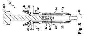
図1‐4の実施形態に共通する要素が同じ符号で識別される、図8‐11に示される実施形態では、プランジャロッド28、より具体的には遠位プランジャ部28Dは、ピストン22を備える。この例では、エラストマー材料30は、ピストン22と一体になっている。それは、遠位プランジャ部28Dに、接着、はんだ付け、スナップ嵌合、またはオーバーモールドされることもあり得る。
In the embodiment shown in FIGS. 8-11, elements common to the embodiment of FIGS. 1-4 are identified by the same reference numerals, the
アセンブリ10の動作は、前述のものと同様である。ピストン22が、すなわちプランジャロッドの遠位部28Dが、図9に示されるように、そのストローク端に到達すると、ユーザーが安全装置12を作動させたい場合、シリンジ本体16内でプランジャを動かすのに使用される力よりも大きい力が、図10のように、この例では軸方向および径方向に、エラストマー材料30を変形させるのに、および近位部28Pをタング44と協働させ、タング44を径方向に変形させて保持手段36および38をアンロックするのに、必要とされる。エラストマー材料30の変形によって、遠位部28Dに対する近位トリガ部28Pの移動が可能になり、従って近位部28Pがそのストローク端に到達する。
The operation of the
図5‐7に示される別の望ましい実施形態では、図1‐4の実施形態に共通する要素は、同じ符号で識別される。 In another preferred embodiment shown in FIGS. 5-7, elements common to the embodiments of FIGS. 1-4 are identified with the same reference numerals.
安全装置12およびシリンジ14は、プランジャロッド28を除き、先の実施形態で説明されたものと同様である。
The
図5‐7の実施形態では、プランジャロッド28は、ピストンにねじ込まれた遠位プランジャ部28Dと、駆動ばね52によって遠位部に連結された近位部28Pと、を備える。
In the embodiment of FIGS. 5-7, the
近位トリガ部28Pは、本質的に平坦な底部54および環状壁70を有する、一般的なキャップの形を取る。平坦な底部54は、内部環状突起56を支え、内部環状突起56は、近位部28P内の中央に駆動ばね52が位置するのを助け、平坦な底部54は、駆動ばね52用のシートを形成する。環状壁70の外径は、タング44の内径よりも大きい。
The
遠位部28Dは、その遠位端58に、駆動ばね52を受容する溝60を備える。溝60は、外側環状壁64および内部円筒状突起62によって形成され、内部円筒状突起62は、環状突起56に摺接して収容される。
近位部28Pおよび遠位部28Dは、相補的なスナップ固定手段66,68を備える。スナップ固定手段は、一方では、遠位部28Dの近位端58の外側環状壁64で支持されるビード66によって形成され、他方では、近位部28Pの環状壁70の内面で支持されるラグ68によって形成される。駆動ばね52が、内部環状突起56の周りで、キャップ形の近位部28P内に配置されると、近位部は、遠位部28Dに取り付けられる。駆動ばね52は、2つの部分28P,28Dの間で圧縮状態にある。駆動ばね52の力に対抗する相補的なスナップ固定手段66,68は、遠位部28Dと近位部28Pとを一緒に固定する。
The
プランジャロッド28は、遠位部28Pに対する近位部28Pの回転を回避する回転防止手段を備える。回転防止手段は、一方では、近位部28Pの環状壁70の内面で支持されるラグ68を備え、他方では、外側環状壁64に形成された溝72を備える。これらの回転防止手段68,72は、相補的であり、互いに協働する。この例では、ラグ68は、スナップ固定手段も回転防止手段も形成していることが、留意されるべきである。これらの相補的な回転防止手段により、ピストンへのプランジャロッド28のねじ込みが容易になる。
The
アセンブリ10の動作は、先の実施形態に関して説明されたものと同様である。プランジャロッド28の遠位部28Pが、図6のようにそのストローク端に到達すると、すなわち、ピストン22がシリンジ本体の遠位端16Dと接触するときに、ユーザーは、安全装置を作動させたいかどうかを決めることができる。プランジャロッドの近位部28Pは、そのストローク端にまだ到達していない。
The operation of
安全装置12が作動される必要があれば、駆動ばね52をさらに圧縮して、近位部28Pを、図7のように、そのストローク端の位置にするように、ピストンロッド28の近位部28Pに加えられる補足的な力を要する。実際には、駆動ばね52を圧縮させるのに要する力は、シリンジ本体内でピストンを動かすのに要する力よりも大きい。
If the
環状壁70の外径は、タング44の内径よりも大きく、近位部28Pがタング44に到達したときに、近位部28Pは、タング44を脇へ押して径方向に変形させ、第1および第2保持手段38,36を切り離す。それ故、戻り止めになる、ばね40に対向する力はない。安全装置12は作動され、プランジャロッド28の近位部28Pは、そのストローク端に到達している。
The outer diameter of the
ばね40によって駆動されて、先に説明されたのと同様に、サポート26に対するシース24の移動が引き起こされ、シースはその安全位置を取る。
Driven by the
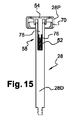
図15に示される実施形態のプランジャロッド28は、図5‐7のものと同様である。近位トリガ部28Pは、本質的に平坦な底部54、環状壁70および内部円筒状突起78を有する、一般的なキャップの形を取る。駆動ばね52は、プランジャロッドの遠位部28Dの近位端58に収められた空間76に受容され、内部円筒状突起78は、安全装置の作動に際して駆動ばね52を圧縮するように、空間76内をスライド自在に移動可能である。
The
図12‐14は、図5‐7の実施形態と同様の、別の実施形態を示し、針18は、ルアーロック74と称される固定エンドピースを介して、シリンジ本体16に取り付けられている。ルアーロック74により、プレフィルドシリンジは、安全装置12の有無にかかわらず、シリンジ本体に取り付けられる針なしで保管できる。従って、保管中に、シリンジはよりコンパクトである。
FIGS. 12-14 illustrate another embodiment, similar to the embodiment of FIGS. 5-7, wherein the
ルアーロックによって、シリンジ本体16で支えられる針18を変更することもできる。例えば、即席注射の場合に、第1の針が、溶媒をバイアルに注入するのに使用され、通常はより細い第2の針が、再構成された混合物を患者の体内に注入するのに使用される。
The
図16に示される実施形態では、弾性手段は弾性ラグを備え、弾性ラグは、プランジャロッド28の遠位部28Dを近位部28Pに接続する。
In the embodiment shown in FIG. 16, the elastic means comprises an elastic lug, which connects the
弾性変形手段が説明されたが、変形手段は、可塑性であることも可能であり、変形手段を塑性的に変形させるのに必要な力は、シースの移動が引き起こされる行程で、シリンジ本体内でピストンを動かすのに必要な力よりも大きい。 Although the elastic deformation means has been described, the deformation means can also be plastic, and the force required to plastically deform the deformation means is the stroke that causes the sheath to move, within the syringe body. Greater than the force required to move the piston.
図17に示されるように、プランジャロッド28の近位部28Pは、遠位部28Dの近位端と近位トリガ部の環状壁70との間の、複数の破断可能なリンク82を備える。プランジャロッド28の遠位部28Pに取り付けられたピストン22(図17に図示せず)が、シリンジ本体の遠位端16Dと接触するときに、ユーザーは、安全装置を作動させたいかどうかを決めることができる。プランジャロッドの近位部28Pは、そのストローク端にまだ到達していない。安全装置を作動させるために、プランジャロッド28の遠位部28Dがそのストローク端に到達すると、ユーザーは、近位部28Pをそのストローク端に到達させるのに、および近位部28Pをタング44と協働させ、タング44を径方向に変形させて保持手段36および38をアンロックするのに、破断可能なリンクを破断する追加的な力を加える必要がある。
As shown in FIG. 17, the
リンク82が、破断可能である代わりに、弾性的にまたは塑性的に、変形可能でもあり得ることが、留意されるべきである。
It should be noted that the
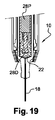
図18および19は、シリンジ14および安全装置12のアセンブリ10の第8実施形態を示し、プランジャロッド28は、近位トリガ部28Pを受容する中空円筒状遠位部28Dを備える。近位部28Pは、遠位部28D内をスライド自在に移動可能である。中空円筒状遠位部28Dは、その内面の遠位端で突起84を支える。図18の実施形態では、突起84は円錐形を有し、その断面は、装置の近位端に向かって減少する。プランジャロッド28の近位部28Pは、変形可能な環状突起86を支え、環状突起86は、遠位部28Dの内面で支えられる突起84と協働する。注入に際して、環状突起86は突起84を押し、注入に要する力は、環状突起86を変形させるのに必要な力よりも小さく、近位部28Pも遠位部28Dも、シリンジの本体16内を一緒にスライドする。プランジャロッド28の遠位部28Dの遠位端に取り付けられたピストン22が、シリンジ本体の遠位端16Dと接触するときに、ユーザーは、安全装置を作動させたいかどうかを決めることができる。プランジャロッドの近位部28Pは、そのストローク端にまだ到達していない。安全装置を作動させるために、プランジャロッド28の遠位部28Dがそのストローク端に到達すると、ユーザーは、突起84が環状突起86内に受容されるように、環状突起86を変形させる追加的な力を加える必要がある。従って、近位部28Pは、そのストローク端に到達でき、近位部28Pは、タング44と協働でき、タング44を径方向に変形させて保持手段36および38をアンロックする。
18 and 19 show an eighth embodiment of the
弾性手段は、所定値までプレストレスが導入され得る(すなわち、弾性手段は、プレストレス値よりも大きい力がプランジャロッド28の近位トリガ部28Pに及ぼされない限り、変形しない)ことが、留意されるべきである。
It is noted that the elastic means may be prestressed to a predetermined value (ie, the elastic means will not deform unless a force greater than the prestress value is exerted on the
スラストばね40の剛性は、安全装置を作動させるのに必要な力に応じて適合されてよい。
The rigidity of the
安全装置は、シリンジサポートなしで動作することもでき、シースはシリンジ本体に取り付けられる。 The safety device can also operate without a syringe support and the sheath is attached to the syringe body.
プランジャロッドはシーリングビードを備えてもよく、それ故、前述のピストンは不要である。従って、遠位プランジャロッドがシリンジ本体の遠位端と接触したときに、プランジャロッドのストローク端が到達する。
The plunger rod may be provided with a sealing bead and therefore the aforementioned piston is not necessary. Thus, the stroke end of the plunger rod arrives when the distal plunger rod contacts the distal end of the syringe body.
Claims (9)
‐遠位プランジャ部(28D)と、
‐近位トリガ部(28P)と、
を含み、
遠位プランジャ部(28D)は、シリンジの本体(16)内をスライド自在に移動可能であり、
近位トリガ部(28P)は、保護シース(24)の、前記針(18)が覆われていない注入位置から前記針(18)が前記シース(24)で覆われる安全位置に向かう移動を、引き起こすように構成され、
近位トリガ部(28P)は、前記保護シース(24)の移動を引き起こすように、遠位プランジャ部がそのストロークの遠位端に達すると、遠位プランジャ部(28D)に対して動くことができ、遠位プランジャ部(28D)および近位トリガ部(28P)は、近位トリガ部(28P)に対する遠位プランジャ部(28D)の回転を回避する相補的な回転防止手段(68,72)をそれぞれ備えることを特徴とする、安全装置。 A safety device (12) for a prefilled injection syringe (14), wherein the injection syringe is attached to a body (16) to which an injection needle (18) is attached and to be movable within the body (16). The safety device (12) comprises a plunger rod (28) screwed into the piston (22), the plunger rod (28) comprising:
-A distal plunger part (28D);
-A proximal trigger part (28P);
Only including,
The distal plunger (28D) is slidably movable within the syringe body (16);
The proximal trigger portion (28P) moves the protective sheath (24) from an injection position where the needle (18) is not covered toward a safe position where the needle (18) is covered by the sheath (24), Configured to cause and
The proximal trigger portion (28P) may move relative to the distal plunger portion (28D) when the distal plunger portion reaches the distal end of its stroke to cause movement of the protective sheath (24). The distal plunger portion (28D) and the proximal trigger portion (28P) can be complementary anti-rotation means (68, 72) to avoid rotation of the distal plunger portion (28D) relative to the proximal trigger portion (28P) A safety device comprising:
Applications Claiming Priority (3)
| Application Number | Priority Date | Filing Date | Title |
|---|---|---|---|
| EP13305010.4A EP2752211A1 (en) | 2013-01-07 | 2013-01-07 | Safety device for an injection syringue |
| EP13305010.4 | 2013-01-07 | ||
| PCT/EP2013/077826 WO2014106600A1 (en) | 2013-01-07 | 2013-12-20 | Safety device for an injection syringe |
Publications (2)
| Publication Number | Publication Date |
|---|---|
| JP2016501692A JP2016501692A (en) | 2016-01-21 |
| JP6280138B2 true JP6280138B2 (en) | 2018-02-14 |
Family
ID=47628075
Family Applications (1)
| Application Number | Title | Priority Date | Filing Date |
|---|---|---|---|
| JP2015551167A Active JP6280138B2 (en) | 2013-01-07 | 2013-12-20 | Safety device for injection syringe |
Country Status (11)
| Country | Link |
|---|---|
| US (1) | US9446204B2 (en) |
| EP (2) | EP2752211A1 (en) |
| JP (1) | JP6280138B2 (en) |
| KR (1) | KR20150105403A (en) |
| CN (1) | CN105263549B (en) |
| BR (1) | BR112015015559A2 (en) |
| CA (1) | CA2892256A1 (en) |
| HK (1) | HK1211522A1 (en) |
| MX (1) | MX358723B (en) |
| RU (1) | RU2674924C2 (en) |
| WO (1) | WO2014106600A1 (en) |
Families Citing this family (11)
| Publication number | Priority date | Publication date | Assignee | Title |
|---|---|---|---|---|
| US20150367083A1 (en) * | 2013-02-06 | 2015-12-24 | Weibel Cds Ag | Dispensing device for dispensing a fluid |
| GB2529621B (en) * | 2014-08-21 | 2016-12-07 | Owen Mumford Ltd | Safety syringe |
| WO2016101031A1 (en) | 2014-12-23 | 2016-06-30 | Davoodi Pty Ltd | Delivery apparatus, system and associated methods |
| BR112017026138B1 (en) * | 2015-06-03 | 2022-08-02 | Injecto Group A/S | INJECTOR TO PREVENT ACCIDENTAL NEEDLE ADHERENCES |
| GB201600989D0 (en) * | 2016-01-19 | 2016-03-02 | Owen Mumford Ltd | Safety syringe apparatus |
| GB2546499A (en) | 2016-01-19 | 2017-07-26 | Owen Mumford Ltd | Safety syringe |
| KR101707884B1 (en) * | 2016-05-10 | 2017-02-17 | (주)에프에이 | An Injection Filter |
| WO2018025274A1 (en) * | 2016-08-05 | 2018-02-08 | Bharat Serums And Vaccines Ltd | A safety housing based implant/ medicament injecting system |
| WO2019158538A1 (en) * | 2018-02-19 | 2019-08-22 | Becton Dickinson France | An injection system comprising a syringe and a protective assembly |
| US11957542B2 (en) | 2020-04-30 | 2024-04-16 | Automed Patent Holdco, Llc | Sensing complete injection for animal injection device |
| CN213554490U (en) * | 2020-09-18 | 2021-06-29 | 山东威高普瑞医药包装有限公司 | Safety device for a prefilled syringe and injection device |
Family Cites Families (32)
| Publication number | Priority date | Publication date | Assignee | Title |
|---|---|---|---|---|
| US4064879A (en) * | 1976-04-06 | 1977-12-27 | Metatech Corporation | Pressure-indicating syringe |
| US5085640A (en) * | 1990-04-06 | 1992-02-04 | Gibbs Andrew H | Non-reusable medical needle apparatus |
| EP0693946B1 (en) * | 1993-03-24 | 2001-05-16 | Owen Mumford Limited | Improvements relating to injection devices |
| US5314415A (en) * | 1993-07-21 | 1994-05-24 | Sterling Winthrop Inc. | Aspirating plunger for power injector cartridges |
| US5411489A (en) * | 1994-05-06 | 1995-05-02 | Sterling Winthrop Inc. | Pre-filled syringe and pre-filled cartridge having actuating cylinder/plunger rod combination for reducing syringing force |
| US5562626A (en) * | 1995-09-11 | 1996-10-08 | Sanpietro; Joseph A. | Safety syringe |
| SE9803662D0 (en) * | 1998-10-26 | 1998-10-26 | Pharmacia & Upjohn Ab | autoinjector |
| US20020091361A1 (en) * | 1999-09-09 | 2002-07-11 | Rosoff Jack P. | Multiple-dose syringe |
| CN1184303C (en) * | 2000-03-21 | 2005-01-12 | 王振山 | Wine for mourishing blood, heart and brain |
| DE60204293T2 (en) * | 2001-03-05 | 2006-02-02 | Becton Dickinson France | SAFETY SYRINGE |
| AUPR373001A0 (en) * | 2001-03-14 | 2001-04-12 | Glenord Pty Ltd | Improved non-reusable syringe |
| FR2830765B1 (en) * | 2001-10-15 | 2004-07-23 | Plastic Omnium Cie | SAFETY DEVICE FOR A SYRINGE |
| US6976976B2 (en) * | 2002-03-27 | 2005-12-20 | Safety Syringes, Inc. | Syringe with needle guard injection device |
| US20040039337A1 (en) * | 2002-08-21 | 2004-02-26 | Letzing Michael Alexander | Portable safety auto-injector |
| DK1551482T3 (en) * | 2002-10-11 | 2012-04-10 | Becton Dickinson Co | Single-use syringe with safety shield |
| GB0312852D0 (en) * | 2003-06-05 | 2003-07-09 | Owen Mumford Ltd | Improvements relating to syringe firing mechanisms |
| FR2861310B1 (en) * | 2003-10-22 | 2006-09-22 | Plastef Investissements | SECURE INJECTION SYRINGE DEVICE |
| FR2861598B1 (en) * | 2003-10-29 | 2006-06-16 | Plastef Investissements | SECURE INJECTION DEVICE FOR A SYRINGE |
| WO2005089831A1 (en) * | 2004-03-16 | 2005-09-29 | Glenord Pty Ltd | Single use retractable syringe |
| US20090270803A1 (en) * | 2006-06-16 | 2009-10-29 | Marc Brunel | Safety device for injecting a medicinal product, such as a lyophilized product |
| FR2905273B1 (en) * | 2006-09-06 | 2009-04-03 | Becton Dickinson France Soc Pa | AUTOMATIC INJECTION DEVICE WITH TIMING MEANS. |
| DE202007005394U1 (en) * | 2007-04-13 | 2007-08-09 | B. Braun Melsungen Ag | Safety nozzle, has piston rod whose release movement is enabled in distal direction relative to nozzle cylinder during attachment of piston to distal front wall of piston rod, in order to release retaining flange |
| CN101854966B (en) * | 2007-09-25 | 2012-10-10 | 贝克顿迪金森法国公司 | Autoinjector received in external socket |
| FR2922112B1 (en) * | 2007-10-11 | 2009-12-04 | Rexam Pharma La Verpilliere | SAFETY DEVICE FOR A LIQUID INJECTION SYRINGE AND SYRINGE ASSEMBLY COMPRISING SAID DEVICE |
| US7976510B2 (en) * | 2008-02-28 | 2011-07-12 | Becton, Dickinson And Company | Syringe with adjustable two piece plunger rod |
| JP5611208B2 (en) * | 2008-08-05 | 2014-10-22 | アンタレス・ファーマ・インコーポレーテッド | Multiple dose injection device |
| GB0823693D0 (en) * | 2008-12-31 | 2009-02-04 | Owen Mumford Ltd | Autoinjector |
| EP2482872B2 (en) * | 2009-09-30 | 2019-12-11 | Sanofi-Aventis Deutschland GmbH | Method for assembling a drug delivery device, assembly for a drug delivery device and piston rod for a drug delivery device |
| CN104689426B (en) * | 2009-10-21 | 2018-10-02 | 欧文蒙福德有限公司 | Automatic injector |
| FR2959419B1 (en) * | 2010-04-28 | 2013-06-28 | Rexam Healthcare La Verpillier | SAFETY DEVICE FOR PRE-FILLED INJECTION SYRINGE |
| US8728040B2 (en) * | 2010-06-23 | 2014-05-20 | Tcb Medical Devices, Llc | Injector for auto-injection of medication and associated method of use |
| GB2487235A (en) * | 2011-01-17 | 2012-07-18 | Owen Mumford Ltd | Injection device with pneumatic damping of the drive mechanism |
-
2013
- 2013-01-07 EP EP13305010.4A patent/EP2752211A1/en not_active Withdrawn
- 2013-12-20 JP JP2015551167A patent/JP6280138B2/en active Active
- 2013-12-20 RU RU2015129462A patent/RU2674924C2/en not_active IP Right Cessation
- 2013-12-20 WO PCT/EP2013/077826 patent/WO2014106600A1/en active Application Filing
- 2013-12-20 BR BR112015015559A patent/BR112015015559A2/en active Search and Examination
- 2013-12-20 EP EP13814151.0A patent/EP2941288B1/en active Active
- 2013-12-20 KR KR1020157021187A patent/KR20150105403A/en not_active Application Discontinuation
- 2013-12-20 CN CN201380069764.XA patent/CN105263549B/en active Active
- 2013-12-20 CA CA2892256A patent/CA2892256A1/en not_active Abandoned
- 2013-12-20 MX MX2015007654A patent/MX358723B/en active IP Right Grant
-
2014
- 2014-01-06 US US14/148,115 patent/US9446204B2/en active Active
-
2015
- 2015-12-16 HK HK15112405.7A patent/HK1211522A1/en unknown
Also Published As
| Publication number | Publication date |
|---|---|
| EP2941288A1 (en) | 2015-11-11 |
| BR112015015559A2 (en) | 2017-07-11 |
| MX2015007654A (en) | 2015-11-16 |
| US9446204B2 (en) | 2016-09-20 |
| HK1211522A1 (en) | 2016-05-27 |
| RU2674924C2 (en) | 2018-12-13 |
| CN105263549B (en) | 2017-11-24 |
| RU2015129462A (en) | 2017-02-09 |
| KR20150105403A (en) | 2015-09-16 |
| CA2892256A1 (en) | 2014-07-10 |
| EP2752211A1 (en) | 2014-07-09 |
| CN105263549A (en) | 2016-01-20 |
| JP2016501692A (en) | 2016-01-21 |
| WO2014106600A1 (en) | 2014-07-10 |
| MX358723B (en) | 2018-09-03 |
| EP2941288B1 (en) | 2021-05-05 |
| US20140194828A1 (en) | 2014-07-10 |
Similar Documents
| Publication | Publication Date | Title |
|---|---|---|
| JP6280138B2 (en) | Safety device for injection syringe | |
| KR101230434B1 (en) | Prefilled retractable syringe, plunger and needle assembly therefor | |
| TWI498138B (en) | Injection device | |
| EP3116568B1 (en) | Automatic medication injection device | |
| US9259537B2 (en) | Injection device with retractable needle | |
| RU2678410C2 (en) | Activator for automatic injector | |
| WO2006008086A1 (en) | Safety kit for protecting the needle of a standard syringe, a glass syringe or a carpule | |
| US20160346483A1 (en) | Injection needle covering system | |
| KR20160137658A (en) | Medicament delivery device | |
| KR102209807B1 (en) | Cap with hemispherical part for medical injector | |
| JP4125491B2 (en) | Safety assembly for prefilled syringes for injecting liquids, especially drugs | |
| CN112996552B (en) | Cap remover with gasket compression | |
| JP2021514238A (en) | Injection system with syringe and protective assembly | |
| US10758677B2 (en) | Drive mechanism | |
| US7662131B2 (en) | Liquid-injection syringe assembly, and a sheath for the assembly | |
| EP3274028B1 (en) | Deformable piston washer | |
| US11103647B2 (en) | Injection device comprising a cover cap and a system for preventing the cover cap from being remounted | |
| US20220080124A1 (en) | Drug reservoir for separate storage of substances |
Legal Events
| Date | Code | Title | Description |
|---|---|---|---|
| A621 | Written request for application examination |
Free format text: JAPANESE INTERMEDIATE CODE: A621 Effective date: 20161101 |
|
| A977 | Report on retrieval |
Free format text: JAPANESE INTERMEDIATE CODE: A971007 Effective date: 20170824 |
|
| A131 | Notification of reasons for refusal |
Free format text: JAPANESE INTERMEDIATE CODE: A131 Effective date: 20170829 |
|
| A521 | Request for written amendment filed |
Free format text: JAPANESE INTERMEDIATE CODE: A523 Effective date: 20171129 |
|
| TRDD | Decision of grant or rejection written | ||
| A01 | Written decision to grant a patent or to grant a registration (utility model) |
Free format text: JAPANESE INTERMEDIATE CODE: A01 Effective date: 20171219 |
|
| A61 | First payment of annual fees (during grant procedure) |
Free format text: JAPANESE INTERMEDIATE CODE: A61 Effective date: 20180118 |
|
| R150 | Certificate of patent or registration of utility model |
Ref document number: 6280138 Country of ref document: JP Free format text: JAPANESE INTERMEDIATE CODE: R150 |
|
| R250 | Receipt of annual fees |
Free format text: JAPANESE INTERMEDIATE CODE: R250 |
|
| R250 | Receipt of annual fees |
Free format text: JAPANESE INTERMEDIATE CODE: R250 |
|
| R250 | Receipt of annual fees |
Free format text: JAPANESE INTERMEDIATE CODE: R250 |