JP6278000B2 - FUEL CELL SYSTEM, FUEL CELL VEHICLE, AND METHOD FOR CONTROLLING FUEL CELL SYSTEM - Google Patents
FUEL CELL SYSTEM, FUEL CELL VEHICLE, AND METHOD FOR CONTROLLING FUEL CELL SYSTEM Download PDFInfo
- Publication number
- JP6278000B2 JP6278000B2 JP2015106092A JP2015106092A JP6278000B2 JP 6278000 B2 JP6278000 B2 JP 6278000B2 JP 2015106092 A JP2015106092 A JP 2015106092A JP 2015106092 A JP2015106092 A JP 2015106092A JP 6278000 B2 JP6278000 B2 JP 6278000B2
- Authority
- JP
- Japan
- Prior art keywords
- power
- fuel cell
- secondary battery
- vehicle
- upper limit
- Prior art date
- Legal status (The legal status is an assumption and is not a legal conclusion. Google has not performed a legal analysis and makes no representation as to the accuracy of the status listed.)
- Active
Links
Images


Classifications
-
- Y—GENERAL TAGGING OF NEW TECHNOLOGICAL DEVELOPMENTS; GENERAL TAGGING OF CROSS-SECTIONAL TECHNOLOGIES SPANNING OVER SEVERAL SECTIONS OF THE IPC; TECHNICAL SUBJECTS COVERED BY FORMER USPC CROSS-REFERENCE ART COLLECTIONS [XRACs] AND DIGESTS
- Y02—TECHNOLOGIES OR APPLICATIONS FOR MITIGATION OR ADAPTATION AGAINST CLIMATE CHANGE
- Y02E—REDUCTION OF GREENHOUSE GAS [GHG] EMISSIONS, RELATED TO ENERGY GENERATION, TRANSMISSION OR DISTRIBUTION
- Y02E60/00—Enabling technologies; Technologies with a potential or indirect contribution to GHG emissions mitigation
- Y02E60/30—Hydrogen technology
- Y02E60/50—Fuel cells
Description
本発明は、車両に搭載される燃料電池システム、燃料電池車両、および、その制御方法に関する。 The present invention relates to a fuel cell system mounted on a vehicle, a fuel cell vehicle, and a control method thereof.
従来から、車両に搭載される燃料電池システムにおいて、アクセル踏込量に応じて燃料電池の発電要求電力(指令電力)を算出し、燃料電池の発電電力が指令電力に一致するように、燃料電池に供給される酸素量および水素量を制御するものが知られている(特許文献1)。この燃料電池システムは、車両の減速時のようにモーターの消費電力が減少するときには、燃料電池の指令電力を減少させる。 Conventionally, in a fuel cell system mounted on a vehicle, the required power generation (command power) of the fuel cell is calculated in accordance with the accelerator depression amount, and the fuel cell is configured so that the generated power of the fuel cell matches the command power. One that controls the amount of oxygen and the amount of hydrogen supplied is known (Patent Document 1). This fuel cell system reduces the command power of the fuel cell when the power consumption of the motor decreases, such as during deceleration of the vehicle.
しかしながら、アクセル踏込量の急減などによってモーターの消費電力が急減した場合に、対応して燃料電池の発電電力が減少するまでに時間的な遅れがあるため、その間に発電された電力の過剰分は二次電池に充電され、二次電池において過充電が発生する問題があった。 However, when the power consumption of the motor suddenly decreases due to a sudden decrease in the amount of accelerator depression, there is a time lag until the power generation power of the fuel cell decreases correspondingly, so the excess power generated during that time is There was a problem that the secondary battery was charged and overcharge occurred in the secondary battery.
本発明は、上述の課題を解決するためになされたものであり、以下の形態として実現することが可能である。
本発明の第1の形態は、
車両に搭載される燃料電池システムであって、
前記車両を駆動するモーターに電力を供給する燃料電池と、
前記モーターに電力を供給する二次電池と、
前記二次電池の温度および蓄電量を検出するSOC検出部と、
前記車両のアクセル踏込量を検出するアクセル位置検出部と、
前記燃料電池の発電電力を制御する制御部と、を備え、
前記制御部は、
前記アクセル踏込量と、前記二次電池の温度を用いて検出された前記二次電池の蓄電量とに基づいて、前記燃料電池に指令される発電要求電力を算出する発電要求電力算出部と、
前記アクセル踏込量と、前記二次電池の温度および蓄電量とに基づいて、前記燃料電池が発電可能な上限要求電力を算出する上限要求電力算出部と、を備え、
前記上限要求電力には、前記二次電池の温度および蓄電量に基づいて算出された許容充電電力が含まれており、
前記制御部は、
前記モーターの消費電力が急減する条件として予め設定されている条件を満たしたか否かを判定し、
前記条件を満たしていると判定すると、前記許容充電電力をゼロにして前記上限要求電力を算出し、
前記条件を満たしていないと判定すると、前記二次電池の温度および蓄電量に基づいて算出された許容充電電力を用いて前記上限要求電力を算出し、
算出した前記発電要求電力が算出した前記上限要求電力を上回る場合、前記燃料電池に対して、算出した前記上限要求電力に対応した発電を実行させる、
燃料電池システムである。
本発明の第2の形態は、
車両に搭載される燃料電池システムであって、
前記車両を駆動するモーターに電力を供給する燃料電池と、
前記モーターに電力を供給する二次電池と、
前記二次電池の温度および蓄電量を検出するSOC検出部と、
前記車両のアクセル踏込量を検出するアクセル位置検出部と、
前記アクセル踏込量と、前記二次電池の温度を用いて検出された前記二次電池の蓄電量とに基づいて、前記燃料電池に指令される発電要求電力を算出する制御部と、を備え、
前記発電要求電力には、前記二次電池の温度および蓄電量に応じて算出される充電電力が含まれており、
前記制御部は、
前記モーターの消費電力が急減する条件として予め設定されている条件を満たしたか否かを判定し、
前記条件を満たしていると判定すると、前記二次電池の温度および蓄電量に基づいて算出された充電電力をゼロにして前記発電要求電力を算出し、
前記条件を満たしていないと判定すると、前記二次電池の温度および蓄電量に基づいて算出された充電電力を用いて前記発電要求電力を算出する、
燃料電池システムである。
本発明の第3の形態は、
車両に搭載される燃料電池システムであって、
前記車両を駆動するモーターに電力を供給する燃料電池と、
前記モーターに電力を供給する二次電池と、
前記二次電池の温度および蓄電量を検出するSOC検出部と、
前記車両のアクセル踏込量を検出するアクセル位置検出部と、
前記燃料電池の発電電力を制御する制御部と、を備え、
前記制御部は、
前記アクセル踏込量と、前記二次電池の温度を用いて検出された前記二次電池の蓄電量とに基づいて、前記燃料電池に指令される発電要求電力を算出する発電要求電力算出部と、
前記アクセル踏込量と、前記二次電池の温度および蓄電量とに基づいて、前記燃料電池が発電可能な上限要求電力を算出する上限要求電力算出部と、を備え、
前記上限要求電力には、前記二次電池の温度および蓄電量と、補正係数とに基づいて算出された許容充電電力が含まれており、
前記制御部は、
前記モーターの消費電力が急減する条件として予め設定されている条件を満たしたか否かを判定し、
前記条件を満たしていると判定すると、前記条件を満たしていない場合よりも前記補正係数を低減させることにより前記許容充電電力を低減させて前記上限要求電力を算出し、
前記条件を満たしていないと判定すると、前記条件を満たしている場合よりも前記補正係数を大きくすることにより前記許容充電電力を増加させて前記上限要求電力を算出し、
算出した前記発電要求電力が算出した前記上限要求電力を上回る場合、前記燃料電池に対して、算出した前記上限要求電力に対応した発電を実行させる、
燃料電池システムである。
本発明は以下の形態としても実現することができる。
The present invention has been made to solve the above-described problems, and can be realized as the following forms.
The first aspect of the present invention is:
A fuel cell system mounted on a vehicle,
A fuel cell that supplies power to a motor that drives the vehicle;
A secondary battery for supplying power to the motor;
An SOC detection unit for detecting a temperature and a storage amount of the secondary battery;
An accelerator position detector for detecting an accelerator depression amount of the vehicle;
A control unit for controlling the generated power of the fuel cell,
The controller is
Based on the accelerator depression amount and the storage amount of the secondary battery detected using the temperature of the secondary battery, a required generation power calculation unit that calculates the required generation power commanded to the fuel cell;
An upper limit required power calculation unit that calculates an upper limit required power that can be generated by the fuel cell, based on the accelerator depression amount, the temperature of the secondary battery, and the storage amount;
The upper limit required power includes an allowable charging power calculated based on a temperature and a storage amount of the secondary battery,
The controller is
It is determined whether or not a condition set in advance as a condition for rapidly reducing the power consumption of the motor is satisfied,
If it is determined that the condition is satisfied, the upper limit required power is calculated by setting the allowable charging power to zero,
When it is determined that the condition is not satisfied, the upper limit required power is calculated using the allowable charging power calculated based on the temperature and the charged amount of the secondary battery,
When the calculated power generation required power exceeds the calculated upper limit required power, the fuel cell is caused to execute power generation corresponding to the calculated upper limit required power.
It is a fuel cell system.
The second aspect of the present invention is:
A fuel cell system mounted on a vehicle,
A fuel cell that supplies power to a motor that drives the vehicle;
A secondary battery for supplying power to the motor;
An SOC detection unit for detecting a temperature and a storage amount of the secondary battery;
An accelerator position detector for detecting an accelerator depression amount of the vehicle;
A control unit that calculates the required power generation to be commanded to the fuel cell based on the accelerator depression amount and the storage amount of the secondary battery detected using the temperature of the secondary battery;
The power generation required power includes charging power calculated according to the temperature and the amount of electricity stored in the secondary battery,
The controller is
It is determined whether or not a condition set in advance as a condition for rapidly reducing the power consumption of the motor is satisfied,
When it is determined that the condition is satisfied, the power generation required power is calculated by setting the charging power calculated based on the temperature and the storage amount of the secondary battery to zero,
When it is determined that the condition is not satisfied, the power generation required power is calculated using the charging power calculated based on the temperature and the amount of power stored in the secondary battery.
It is a fuel cell system.
The third aspect of the present invention is:
A fuel cell system mounted on a vehicle,
A fuel cell that supplies power to a motor that drives the vehicle;
A secondary battery for supplying power to the motor;
An SOC detection unit for detecting a temperature and a storage amount of the secondary battery;
An accelerator position detector for detecting an accelerator depression amount of the vehicle;
A control unit for controlling the generated power of the fuel cell,
The controller is
Based on the accelerator depression amount and the storage amount of the secondary battery detected using the temperature of the secondary battery, a required generation power calculation unit that calculates the required generation power commanded to the fuel cell;
An upper limit required power calculation unit that calculates an upper limit required power that can be generated by the fuel cell, based on the accelerator depression amount, the temperature of the secondary battery, and the storage amount;
The upper limit required power includes an allowable charging power calculated based on a temperature and a storage amount of the secondary battery, and a correction coefficient,
The controller is
It is determined whether or not a condition set in advance as a condition for rapidly reducing the power consumption of the motor is satisfied,
When it is determined that the condition is satisfied, the upper limit required power is calculated by reducing the allowable charging power by reducing the correction coefficient than when the condition is not satisfied,
When it is determined that the condition is not satisfied, the upper limit required power is calculated by increasing the allowable charging power by increasing the correction coefficient than when the condition is satisfied,
When the calculated power generation required power exceeds the calculated upper limit required power, the fuel cell is caused to execute power generation corresponding to the calculated upper limit required power.
It is a fuel cell system.
The present invention can also be realized in the following forms.
(1)本発明の一形態によれば、車両に搭載される燃料電池システムが提供される。この燃料電池システムは、前記車両を駆動するモーターに電力を供給する燃料電池と、前記モーターに電力を供給する二次電池と、前記二次電池の温度および蓄電量を検出するSOC検出部と、前記車両のアクセル踏込量を検出するアクセル位置検出部と、前記燃料電池の発電電力を制御する制御部と、を備え、前記制御部は、前記アクセル踏込量と、前記二次電池の温度および蓄電量とに基づいて、前記燃料電池に指令される発電要求電力を算出する発電要求電力算出部と、前記アクセル踏込量と、前記二次電池の温度および蓄電量とに基づいて、前記燃料電池が発電可能な上限要求電力を算出する上限要求電力算出部と、を備え、前記上限要求電力には、前記二次電池の温度および蓄電量に基づいて算出された許容充電電力が含まれており、前記制御部は、前記モーターの消費電力が急減する条件として予め設定されている条件を満たしたか否かを判定し、前記条件を満たしていると判定すると、前記許容充電電力をゼロにして前記上限要求電力を算出し、前記条件を満たしていないと判定すると、前記二次電池の温度および蓄電量に基づいて算出された許容充電電力を用いて前記上限要求電力を算出し、算出した前記発電要求電力が算出した前記上限要求電力を上回る場合、前記燃料電池に対して、算出した前記上限要求電力に対応した発電を実行させるように構成されている。この構成によれば、モーターの消費電力が急減するときには、二次電池の許容充電電力がゼロになって燃料電池の上限要求電力(指令電力)が減少するため、燃料電池の発電電力を速やかに低減させることができる。これにより、モーター消費電力の急減時における、二次電池の過充電の発生を低減させることができる。 (1) According to one aspect of the present invention, a fuel cell system mounted on a vehicle is provided. The fuel cell system includes a fuel cell that supplies electric power to a motor that drives the vehicle, a secondary battery that supplies electric power to the motor, an SOC detection unit that detects a temperature and a storage amount of the secondary battery, An accelerator position detection unit that detects an accelerator depression amount of the vehicle; and a control unit that controls electric power generated by the fuel cell, wherein the control unit includes the accelerator depression amount, the temperature of the secondary battery, and power storage. The fuel cell based on the power generation required power calculation unit that calculates the power generation required power commanded to the fuel cell based on the amount, the accelerator depression amount, the temperature of the secondary battery, and the storage amount. An upper limit required power calculation unit that calculates an upper limit required power that can be generated, and the upper limit required power includes an allowable charging power calculated based on a temperature and a storage amount of the secondary battery. The control unit determines whether or not a condition set in advance as a condition for rapidly reducing the power consumption of the motor is satisfied, and determines that the condition is satisfied. When the upper limit required power is calculated and it is determined that the condition is not satisfied, the upper limit required power is calculated using the allowable charging power calculated based on the temperature and the charged amount of the secondary battery, and the calculated power generation When the required power exceeds the calculated upper limit required power, the fuel cell is configured to execute power generation corresponding to the calculated upper limit required power. According to this configuration, when the power consumption of the motor suddenly decreases, the allowable charging power of the secondary battery becomes zero and the upper limit required power (command power) of the fuel cell is reduced. Can be reduced. Thereby, the occurrence of overcharge of the secondary battery when the motor power consumption is suddenly reduced can be reduced.
(2)上記形態の燃料電池システムにおいて、前記予め設定されている条件は、前記アクセル踏込量の減少速度が第1の閾値以上となることであってもよい。この構成によれば、モーター消費電力が急減する状態を容易に検出することができる。 (2) In the fuel cell system according to the above aspect, the preset condition may be that a decrease rate of the accelerator depression amount is equal to or greater than a first threshold value. According to this configuration, it is possible to easily detect a state in which the motor power consumption is rapidly reduced.
(3)上記形態の燃料電池システムにおいて、前記予め設定されている条件は、前記車両のシフトポジションがドライブからニュートラルに切り替えられ、かつ、前記燃料電池の発電電力が第2の閾値以上となることであってもよい。この構成によれば、モーター消費電力が急減する状態を容易に検出することができる。 (3) In the fuel cell system of the above aspect, the preset condition is that the shift position of the vehicle is switched from drive to neutral, and the generated power of the fuel cell is equal to or greater than a second threshold value. It may be. According to this configuration, it is possible to easily detect a state in which the motor power consumption is rapidly reduced.
(4)本発明の他の形態によれば、車両に搭載される燃料電池システムが提供される。この燃料電池システムは、前記車両を駆動するモーターに電力を供給する燃料電池と、前記モーターに電力を供給する二次電池と、前記二次電池の温度および蓄電量を検出するSOC検出部と、前記車両のアクセル踏込量を検出するアクセル位置検出部と、前記アクセル踏込量と、前記二次電池の温度および蓄電量とに基づいて、前記燃料電池に指令される発電要求電力を算出する制御部と、を備え、前記発電要求電力には、前記二次電池の温度および蓄電量に応じて算出される充電電力が含まれており、前記制御部は、前記モーターの消費電力が急減する条件として予め設定されている条件を満たしたか否かを判定し、前記条件を満たしていると判定すると、前記二次電池の温度および蓄電量に基づいて算出された充電電力をゼロにして前記発電要求電力を算出し、前記条件を満たしていないと判定すると、前記二次電池の温度および蓄電量に基づいて算出された充電電力を用いて前記発電要求電力を算出するように構成されている。この構成によれば、モーターの消費電力が急減するときには、発電要求電力(指令電力)に含まれる充電電力がゼロになって燃料電池の発電要求電力が減少するため、燃料電池の発電電力を速やかに低減させることができる。これにより、モーター消費電力の急減時における、二次電池の過充電の発生を低減させることができる。 (4) According to another aspect of the present invention, a fuel cell system mounted on a vehicle is provided. The fuel cell system includes a fuel cell that supplies electric power to a motor that drives the vehicle, a secondary battery that supplies electric power to the motor, an SOC detection unit that detects a temperature and a storage amount of the secondary battery, An accelerator position detection unit that detects an accelerator depression amount of the vehicle, and a control unit that calculates an electric power generation request commanded to the fuel cell based on the accelerator depression amount, a temperature and a storage amount of the secondary battery The power required for power generation includes charging power calculated according to the temperature and the amount of power stored in the secondary battery, and the control unit is configured to rapidly reduce the power consumption of the motor. It is determined whether or not a preset condition is satisfied, and if it is determined that the condition is satisfied, the charging power calculated based on the temperature and the storage amount of the secondary battery is set to zero before The power generation request power is calculated, and when it is determined that the condition is not satisfied, the power generation request power is calculated using the charging power calculated based on the temperature and the storage amount of the secondary battery. . According to this configuration, when the power consumption of the motor suddenly decreases, the charging power included in the power generation required power (command power) becomes zero and the power generation required power of the fuel cell decreases. Can be reduced. Thereby, the occurrence of overcharge of the secondary battery when the motor power consumption is suddenly reduced can be reduced.
(5)本発明の他の形態によれば、車両に搭載される燃料電池システムが提供される。この燃料電池システムは、前記車両を駆動するモーターに電力を供給する燃料電池と、前記モーターに電力を供給する二次電池と、前記二次電池の温度および蓄電量を検出するSOC検出部と、前記車両のアクセル踏込量を検出するアクセル位置検出部と、前記燃料電池の発電電力を制御する制御部と、を備え、前記制御部は、前記アクセル踏込量と、前記二次電池の温度および蓄電量とに基づいて、前記燃料電池に指令される発電要求電力を算出する発電要求電力算出部と、前記アクセル踏込量と、前記二次電池の温度および蓄電量とに基づいて、前記燃料電池が発電可能な上限要求電力を算出する上限要求電力算出部と、を備え、前記上限要求電力には、前記二次電池の温度および蓄電量と、補正係数とに基づいて算出された許容充電電力が含まれており、前記制御部は、前記モーターの消費電力が急減する条件として予め設定されている条件を満たしたか否かを判定し、前記条件を満たしていると判定すると、前記条件を満たしていない場合よりも前記補正係数を低減させることにより記許容充電電力を低減させて前記上限要求電力を算出し、前記条件を満たしていないと判定すると、前記条件を満たしている場合よりも前記補正係数を大きくすることにより前記許容充電電力を増加させて前記上限要求電力を算出し、算出した前記発電要求電力が算出した前記上限要求電力を上回る場合、前記燃料電池に対して、算出した前記上限要求電力に対応した発電を実行させるように構成されている。この構成によれば、モーターの消費電力が急減するときには、二次電池の許容充電電力が減少して上限要求電力(指令電力)が減少するため、燃料電池の発電電力を速やかに低減させることができる。これにより、モーター消費電力の急減時における、二次電池の過充電の発生を低減させることができる。 (5) According to another aspect of the present invention, a fuel cell system mounted on a vehicle is provided. The fuel cell system includes a fuel cell that supplies electric power to a motor that drives the vehicle, a secondary battery that supplies electric power to the motor, an SOC detection unit that detects a temperature and a storage amount of the secondary battery, An accelerator position detection unit that detects an accelerator depression amount of the vehicle; and a control unit that controls electric power generated by the fuel cell, wherein the control unit includes the accelerator depression amount, the temperature of the secondary battery, and power storage. The fuel cell based on the power generation required power calculation unit that calculates the power generation required power commanded to the fuel cell based on the amount, the accelerator depression amount, the temperature of the secondary battery, and the storage amount. An upper limit required power calculation unit that calculates an upper limit required power that can be generated, and the upper limit required power includes an allowable charging power calculated based on a temperature and a storage amount of the secondary battery, and a correction coefficient. The control unit determines whether or not a condition set in advance as a condition for rapidly reducing the power consumption of the motor is satisfied, and if the condition is determined to satisfy the condition, the condition is satisfied When the upper limit required power is calculated by reducing the allowable charging power by reducing the correction coefficient than when not satisfying the condition, the correction is performed more than when the condition is satisfied. The upper limit required power is calculated by increasing the allowable charging power by increasing a coefficient, and when the calculated power generation required power exceeds the calculated upper limit required power, the calculated upper limit for the fuel cell is calculated. The power generation corresponding to the required power is executed. According to this configuration, when the power consumption of the motor suddenly decreases, the allowable charging power of the secondary battery decreases and the upper limit required power (command power) decreases, so that the generated power of the fuel cell can be quickly reduced. it can. Thereby, the occurrence of overcharge of the secondary battery when the motor power consumption is suddenly reduced can be reduced.
(6)上記形態の燃料電池システムにおいて、前記予め設定されている条件は、前記予め設定されている条件は、ブレーキによる前記車両の制動力が前記モーターによる前記車両の駆動力よりも大きくなることであってもよい。この構成によれば、モーター消費電力が急減する状態を容易に検出することができる。 (6) In the fuel cell system according to the above aspect, the preset condition is that the braking force of the vehicle by a brake is larger than the driving force of the vehicle by the motor. It may be. According to this configuration, it is possible to easily detect a state in which the motor power consumption is rapidly reduced.
(7)上記形態の燃料電池システムにおいて、前記制御部は、前記条件を満たしていると判定したときにおいて、前記アクセル踏込量が予め設定された値以下の場合には、前記アクセル踏込量が前記予め設定された値よりも大きい場合よりも前記補正係数を大きくする、この構成によれば、アクセル踏込量が小さい場合であっても、燃料電池の発電電力の低下によって燃料電池の電位が上昇することを抑制できる。 (7) In the fuel cell system of the above aspect, when the control unit determines that the condition is satisfied, and the accelerator depression amount is equal to or less than a preset value, the accelerator depression amount is According to this configuration, the correction coefficient is made larger than when the value is larger than a preset value. According to this configuration, even when the accelerator depression amount is small, the potential of the fuel cell increases due to a decrease in the generated power of the fuel cell. This can be suppressed.
なお、本発明は、種々の態様で実現することが可能であり、例えば、燃料電池を搭載した車両、車両に搭載される燃料電池システムの制御方法、この制御方法を実行する制御装置、この制御方法を実現するコンピュータプログラム、そのコンピュータプログラムを記録した記録媒体などの形態で実現することができる。 The present invention can be realized in various modes. For example, a vehicle on which a fuel cell is mounted, a control method for a fuel cell system mounted on the vehicle, a control device that executes this control method, and this control The present invention can be realized in the form of a computer program for realizing the method, a recording medium on which the computer program is recorded, and the like.
A.第1実施形態:
図1は、第1実施形態の燃料電池システム100を搭載した燃料電池車両10の構成を示す概略図である。燃料電池車両10は、燃料電池110と、FC昇圧コンバーター120と、パワーコントロールユニット(PCU)130と、トラクションモーター136と、エアコンプレッサー(ACP)138と、車速検出部139と、二次電池140と、SOC検出部142と、FC補機150と、制御装置180と、アクセル位置検出部190と、車輪WLと、を備える。燃料電池車両10は、燃料電池110および二次電池140から供給される電力によってトラクションモーター136を駆動させて走行する。燃料電池システム100は、例えば、上述した燃料電池車両10の機能部のうち、トラクションモーター136と、車輪WLとを除いた機能部によって構成される。
A. First embodiment:
FIG. 1 is a schematic diagram showing the configuration of a
燃料電池110は、反応ガスとして水素と酸素の供給を受けて発電する固体高分子形燃料電池である。なお、燃料電池110としては、固体高分子形燃料電池に限らず、他の種々のタイプの燃料電池を採用することができる。燃料電池110は、FC昇圧コンバーター120を介して高圧直流配線DCHに接続され、高圧直流配線DCHを介してPCU130に含まれるモータードライバー132及びACPドライバー137に接続されている。FC昇圧コンバーター120は、燃料電池110の出力電圧VFCをモータードライバー132及びACPドライバー137で利用可能な高圧電圧VHに昇圧する。
The
モータードライバー132は、三相インバーター回路によって構成され、トラクションモーター136に接続されている。モータードライバー132は、FC昇圧コンバーター120を介して供給される燃料電池110の出力電力、および、DC/DCコンバーター134を介して供給される二次電池140の出力電力を三相交流電力に変換してトラクションモーター136に供給する。トラクションモーター136は、三相コイルを備える同期モーターによって構成され、ギア等を介して車輪WLを駆動する。また、トラクションモーター136は、燃料電池車両10の制動時において、燃料電池車両10の運動エネルギーを回生させて回生電力を発生させる発電機としても機能する。車速検出部139は、燃料電池車両10の車速SVHCL[km/h]を検出し、制御装置180に送信する。
The
DC/DCコンバーター134は、制御装置180からの駆動信号に応じて高圧直流配線DCHの電圧レベルを調整し、二次電池140の充電/放電の状態を切り替える。なお、トラクションモーター136において回生電力が発生する場合には、その回生電力は、モータードライバー132によって直流電力に変換され、DC/DCコンバーター134を介して二次電池140に充電される。
The DC /
ACPドライバー137は、三相インバーター回路によって構成され、ACP138に接続されている。ACPドライバー137は、FC昇圧コンバーター120を介して供給される燃料電池110の出力電力、および、DC/DCコンバーター134を介して供給される二次電池140の出力電力を三相交流電力に変換してACP138に供給する。ACP138は、三相コイルを備える同期モーターによって構成され、供給された電力に応じてモーターを駆動させ、発電に使用される酸素(空気)を燃料電池110に供給する。
The
二次電池140は、電力エネルギーを蓄え、充電と放電を繰り返すことができる蓄電装置であり、例えば、リチウムイオン電池で構成することができる。なお、二次電池140としては、鉛蓄電池、ニッケルカドミウム電池、ニッケル水素電池など他の種類の電池であってもよい。二次電池140は、低圧直流配線DCLを介してPCU130に含まれるDC/DCコンバーター134に接続され、さらに、DC/DCコンバーター134を介して高圧直流配線DCHに接続されている。
The
SOC検出部142は、二次電池140の蓄電量(SOC)[%]を検出し、制御装置180に送信する。なお、本明細書において「蓄電量(SOC)」とは、二次電池140の現在の充電容量に対する充電残量の比率を意味する。SOC検出部142は、二次電池140の温度Tbaや、出力電圧V、出力電流Iを検出し、それらの検出値に基づき、蓄電量(SOC)を検出する。なお、本実施形態のSOC検出部142は、二次電池140の温度Tbaについても制御装置180に送信する。
The
FC補機150は、低圧直流配線DCLに接続され、燃料電池110や二次電池140から供給される電力によって駆動する。FC補機150は、燃料電池110に反応ガスを供給する燃料ポンプ、及び、燃料電池110に冷媒を供給する冷媒ポンプ等の燃料電池110の発電のための補機類である。アクセル位置検出部190は、運転者によるアクセルの踏み込み量(アクセル踏込量DACC)[%]を検出し、制御装置180に送信する。
The FC
制御装置180は、中央処理装置と主記憶装置とを備えるマイクロコンピュータによって構成されている。制御装置180は、運転者によるアクセル操作などの操作を検出すると、その操作内容に応じて、燃料電池110の発電や二次電池140の充放電を制御する。制御装置180は、モータードライバー132と、DC/DCコンバーター134とにそれぞれ、アクセル踏込量DACCに応じた駆動信号を生成して送信する。モータードライバー132は、制御装置180の駆動信号に応じて、交流電圧のパルス幅を調整するなどして、トラクションモーター136にアクセル踏込量DACCに応じた回転駆動をさせる。制御装置180は、トラクションモーター136をアクセル踏込量DACCに応じた回転駆動せるために必要な電力に対して、二次電池140が負担する電力の割合(二次電池アシスト率)と、二次電池140の温度および蓄電量(SOC)との関係が示された二次電池アシスト制御マップを備えており、このマップを用いて、二次電池アシスト率を決定する。
The
図2は、制御装置180の構成を説明するための図である。制御装置180は、PM−ECU181と、FC―ECU182と、FDC−ECU183と、MG−ECU184と、の4つのECU(Electronic Control Unit)を含んでいる。PM−ECU181は、燃料電池車両10のアクセル踏込量DACCを取得し、トラクションモーター136をアクセル踏込量DACCに応じた回転数で駆動させるために必要な種々の要求や指令を他のECUに対して発行する。FC―ECU182は、燃料電池110およびFC補機150を制御し、PM−ECU181から、後述する要求信号SREQを受信すると、燃料電池110の発電能力や特性に応じた回答信号SRESをPM−ECU181に発行する。FDC―ECU183は、FC昇圧コンバーター120を制御し、PM−ECU181から、後述するパワー指令PCOMを受信すると、パワー指令PCOMに応じた電力を燃料電池110からトラクションモーター136およびACP138に供給させる。MG−ECU184は、モータードライバー132、ACPドライバー137、および、DC/DCコンバーター134を制御し、PM−ECU181から、後述するトルク指令TCOMを受信すると、トルク指令TCOMに応じたトルクをトラクションモーター136およびACP138に発生させる。4つのECUの具体的な動作の一例を以下で説明する。
FIG. 2 is a diagram for explaining the configuration of the
PM−ECU181は、アクセルペダルが運転者により踏み込まれた際に、アクセル位置検出部190によって検出されたアクセル踏込量DACCを受信する。PM−ECU181は、アクセル踏込量DACCを受信すると、アクセル踏込量DACCに応じたトラクションモーター136の必要なトルク量であるアクセル要求トルクTACC[N・m]を算出する。アクセル要求トルクTACCは、例えば、DACCとTACCとの関係を示す演算式から算出することができる。PM−ECU181は、また、アクセル要求トルクTACCからドラビリ要求トルクTMOD[N・m]を算出する。ドラビリ要求トルクTMODは、アクセル要求トルクTACCの変化量ΔTACC[N・m/s]が閾値(レートリミッター)ΔTth1以上である場合に、変化量ΔTACCに対してレート処理(なめし処理)をおこなって変化量ΔTACCが減少するように算出される。アクセル要求トルクTACCに対応させて燃料電池車両10の加減速を制御すると、加減速が急峻になり快適性が低下するため、ドラビリ要求トルクTMODが設定される。PM−ECU181は、算出したドラビリ要求トルクTMODを含むトルク指令TCOMをMG−ECU184に発行する。MG−ECU184は、ドラビリ要求トルクTMODを含むトルク指令TCOMを受信すると、ドラビリ要求トルクTMODに応じた出力トルクが発生するようにトラクションモーター136を制御する。トラクションモーター136に実際に発生するトルクを実行トルクTACTとも呼ぶ。また、実行トルクの発生によってトラクションモーター136が消費する電力をT/M消費電力PCONSとも呼ぶ。
The PM-ECU 181 receives the accelerator depression amount D ACC detected by the
PM−ECU181は、算出したドラビリ要求トルクTMODから車両要求電力PVHCL[W]を算出する。車両要求電力PVHCLは、燃料電池車両10をドラビリ要求トルクTMODに対応する運転状態とするために必要な電力であり、燃料電池110の発電要求電力(指令電力PCOM)である。車両要求電力PVHCLは、下記の式(1)から算出される。
PVHCL=max{PT/M+PAUX+Pchg ,POC} ・・・(1)
ここで、PT/Mは、トラクションモーター136の駆動要求電力[W]であり、PAUXは、FC補機150やACP138の駆動要求電力[W]であり、Pchgは、二次電池140に充電される電力[W]である。POCは、間欠運転時等において高電位回避電圧とするために必要な電力[W]である。PT/Mは、例えば、トラクションモーター136の回転数および要求トルクと、PT/Mとの関係を示すモーター特性から算出することができる。PAUXは、例えば、現在のFC補機150、ACP138の消費電力の実測値に基づいて算出することができる。なお、PAUXは、FC補機150の消費電力を定数とし、ACP138の消費電力はモーターの回転数、要求トルクと、消費電力との関係を示すモーター特性から算出してもよい。Pchgは、例えば、二次電池140の目標のSOC(例えば、60%)と、現在のSOCと、Pchgとの関係を示したマップから算出することができる。POCは、燃料電池110の電力―電流特性(P−I特性)、電流―電圧特性(I−V特性)から算出することができる。なお、POCは固定値であってもよい。この「車両要求電力PVHCL」は、特許請求の範囲の「燃料電池の発電要求電力」に該当する。「Pchg」は、特許請求の範囲の「充電電力」に該当する。
PM-ECU 181 calculates vehicle required power P VHCL [W] from calculated driveability required torque T MOD . The vehicle required power P VHCL is power required to bring the
P VLCL = max {P T / M + P AUX + P chg , P OC } (1)
Here, P T / M is the required drive power [W] of the
PM−ECU181は、また、算出したドラビリ要求トルクTMODおよび二次電池140の状態から燃料電池110の上限要求電力PMAX[W]を算出する。上限要求電力PMAXは、燃料電池110の発電要求電力、すなわち、車両要求電力PVHCLの上限値(ガード値)である。上限要求電力PMAXは、下記の式(2)から算出される。
PMAX=PT/M+PAUX+α・PWin ・・・(2)
ここで、PWinは、二次電池140の温度および蓄電量に応じて設定される充電電力の上限値[W]である。αは、補正係数である。PWinは、二次電池140のSOC充放電特性および温度充放電特性から算出することができる。SOC充放電特性とは、二次電池140の蓄電量(SOC)と、入力(充電)電力Pinの許容入力上限値Winおよび出力(放電)電力Poutの許容出力上限値Woutと、が対応付けられたマップである。温度充放電特性とは、二次電池140の温度Tbaと、入力電力の許容入力上限値Winおよび出力電力の許容出力上限値Woutと、が対応付けられたマップである。PM−ECU181は、SOC検出部142から取得した蓄電量(SOC)とSOC充放電特性から特定される許容入力上限値Winと、SOC検出部142から取得した温度Tbaと温度充放電特性から特定される許容入力上限値Winと、の小さい方をPWinとして採用することができる。補正係数αは、後述する補正係数設定制御によって算出される。以後、αとPWinとの積(α・PWin)を二次電池140の「許容充電電力」とも呼ぶ。本実施形態の「PM−ECU181」は、特許請求の範囲の「発電要求電力算出部」および「上限要求電力算出部」に該当する。
The PM-ECU 181 also calculates the upper limit required power P MAX [W] of the
P MAX = P T / M + P AUX + α · P Win (2)
Here, P Win is the upper limit [W] of the charging power set according to the temperature of the
PM−ECU181は、それぞれ算出した、車両要求電力PVHCL(指令電力PCOM)と上限要求電力PMAXとの比較をおこない、車両要求電力PVHCLが上限要求電力PMAXを上回っていないか否かを判定する。車両要求電力PVHCLが上限要求電力PMAXを上回っていない場合には、PM−ECU181は、算出した車両要求電力PVHCLを含む要求信号SREQをFC―ECU182に発行する。一方、車両要求電力PVHCLが上限要求電力PMAXを上回っている場合には、上限要求電力PMAXの値を車両要求電力PVHCLとして設定する。その後、値がPMAXの車両要求電力PVHCLを含む要求信号SREQをFC―ECU182に発行する。
The PM-ECU 181 compares the calculated vehicle required power P VHCL (command power P COM ) and the upper limit required power P MAX, and determines whether the vehicle required power P VHCL exceeds the upper limit required power P MAX . Determine. When the vehicle request power P VHCL does not exceed the upper limit required power P MAX is, PM-ECU181 issues a request signal SREQ including the calculated vehicle request power P VHCL the FC-ECU182. On the other hand, when vehicle request power P VHCL exceeds the upper limit required power P MAX sets the value of the upper limit required power P MAX as the vehicle demand power P VHCL. Thereafter, a request signal SREQ including the vehicle required power P HVCL whose value is P MAX is issued to the FC-
FC―ECU182は、車両要求電力PVHCLを含む要求信号SREQを受信すると、車両要求電力PVHCLが燃料電池110の許容電力PALW[W]を越えているか否の判定をおこなう。許容電力PALWとは、現在の燃料電池110が発電可能な電力の上限値であり、燃料電池110の現在の状態を示す種々のパラメーターから算出することができる。燃料電池110の現在の状態を示すパラメーターとは、例えば、燃料電池110の温度、ACP138が取り込む外気の量、燃料電池110に供給される水素を貯蔵する水素タンク内の水素の残量、燃料電池110のアノード圧力およびカソード圧力などが含まれる。FC―ECU182は、これらのパラメーターと許容電力PALWとの対応関係が示されたマップから許容電力PALWを算出することができる。FC―ECU182は、車両要求電力PVHCLが許容電力PALWを越えていなければ、車両要求電力PVHCLに対応する電流値I[A]および電圧値V[V]を含む回答信号SRESをPM−ECU181に発行する。車両要求電力PVHCLに対応する電流値Iおよび電圧値Vは、燃料電池110のP−I特性、I−V特性から算出することができる。FC―ECU182は、車両要求電力PVHCLが許容電力PALWを越えていれば、許容電力PALWに対応する電流値Iおよび電圧値Vを含む回答信号SRESをPM−ECU181に発行する。
When the FC-
PM−ECU181は、車両要求電力PVHCLまたは許容電力PALWに対応する電流値Iおよび電圧値Vを含む回答信号SRESを受信すると、受信した電流値Iおよび電圧値Vをパワー指令PCOMとしてFDC―ECU183に発行する。パワー指令PCOMには、車両要求電力PVHCLまたは許容電力PALWに対応する電流値Iおよび電圧値Vのほかに、上限要求電力PMAXが含まれていてもよい。すなわち、パワー指令PCOMにも上限ガードを実施してもよい。FDC―ECU183は、パワー指令PCOMを受信すると、パワー指令PCOMに応じた電流値Iおよび電圧値Vを燃料電池110が出力するようにFC昇圧コンバーター120を制御する。燃料電池110が実際に出力する電力をFC発電電力PFCとも呼ぶ。パワー指令PCOMに上限要求電力PMAXが含まれている場合、FDC―ECU183は、電流値Iおよび電圧値Vが上限要求電力PMAX以下となるように電流値Iおよび電圧値Vを適宜補正し、補正した電流値Iおよび電圧値Vを燃料電池110が出力するようにFC昇圧コンバーター120を制御してもよい。
When the PM-ECU 181 receives the answer signal SRES including the current value I and the voltage value V corresponding to the vehicle required power P VHCL or the allowable power P ALW , the PM-ECU 181 uses the received current value I and voltage value V as the power command PCOM as the FDC- Issued to the
一方、PM−ECU181は、アクセル要求トルクTACCからACP駆動要求電力PRQ[W]を算出する。ACP駆動要求電力PRQは、ACP138をアクセル要求トルクTACCに対応する駆動状態とするために必要な電力であり、例えば、TACCとPRQとの関係を示す演算式から算出することができる。PM−ECU181は、算出したACP駆動要求電力PRQを含む要求信号SREQをFC―ECU182に発行する。
On the other hand, PM-ECU 181 calculates ACP drive request power P RQ [W] from accelerator request torque T ACC . The ACP drive request power P RQ is power required to set the
FC―ECU182は、ACP駆動要求電力PRQを含む要求信号SREQを受信すると、ACP駆動要求電力PRQに対応するACP138の回転数(必要回転数)RRQ[rpm]を算出する。必要回転数RRQは、例えば、以下の方法で算出することができる。まず、ACP駆動要求電力PRQの値、燃料電池110のP−I特性、I−V特性から、ACP駆動要求電力PRQを発生させるための燃料電池110の電流値Iを算出する。そして、算出した電流値Iに対応する電荷量、および、発電時の電気化学反応式から、ACP駆動要求電力PRQ発生させるための酸素量を算出する。そして、算出した酸素量、および、空気の成分比率から、ACP駆動要求電力PRQを発生させるための空気量を算出し、算出した空気量からACP138の必要回転数RRQを算出する。FC―ECU182は、算出した必要回転数RRQを含む回答信号SRESをPM−ECU181に発行する。
FC-ECU182 receives the request signal SREQ including ACP required driving power P RQ, the rotational speed of ACP138 corresponding to ACP required driving power P RQ (required rotational speed) is calculated R RQ [rpm]. The required rotational speed RRQ can be calculated by the following method, for example. First, the value of the ACP required driving power P RQ, P-I characteristics of the
PM−ECU181は、必要回転数RRQを含む回答信号SRESを受信すると、必要回転数RRQからACP要求トルクTACP[N・m]を算出する。PM−ECU181は、算出したACP要求トルクTACPを含むトルク指令TCOMをMG−ECU184に発行する。MG−ECU184は、ACP要求トルクTACPを含むトルク指令TCOMを受信すると、ACP要求トルクTACPに応じた出力トルクが発生するようにACP138を制御する。
PM-ECU181 receives the reply signal SRES containing the required rotational speed R RQ, calculates the ACP required torque T ACP [N · m] from the required rotation speed R RQ. PM-ECU181 issues a torque command TCOM including the calculated ACP requested torque T ACP on MG-ECU184. When MG-
上述のように、本実施形態のPM−ECU181は、車両要求電力PVHCL(指令電力PCOM)をドラビリ要求トルクTMODから算出し、ACP駆動要求電力PRQをアクセル要求トルクTACCから算出するように構成されている。この構成により、算出した車両要求電力PVHCL、すなわち、燃料電池110の発電要求電力が急減するときには、ACP駆動要求電力PRQの減少速度を、発電要求電力(車両要求電力PVHCL)の減少速度よりも速くすることができる。これにより、車両要求電力PVHCLの急減時における燃料電池110のドライアップの発生や、余剰発電による燃費が悪化を抑制できる。具体的には、ACP138はイナーシャにより応答が遅く、車両要求電力PVHCLが急減した場合に、ACP駆動要求電力PRQがゼロになってもACP138が停止するまで、燃料電池110に酸素が供給される。この余分な酸素の供給により、燃料電池110のドライアップや余剰発電が発生する。一方、ACP駆動要求電力PRQの減少速度を、車両要求電力PVHCLの減少速度よりも速くすることで、ACP駆動要求電力PRQに対してACP138が遅れて供給した酸素量が、その時点において車両要求電力PVHCLに必要な空気量に近づくように構成される。これにより、車両要求電力PVHCLがゼロとなってからの不要な酸素の供給が抑制され、燃料電池110のドライアップや余剰発電が発生抑制することができる。
As described above, the PM-ECU 181 of the present embodiment calculates the vehicle required power P VHCL (command power P COM ) from the drive request torque T MOD and calculates the ACP drive request power P RQ from the accelerator request torque T ACC . It is configured as follows. With this configuration, when the calculated vehicle required power P VHCL , that is, when the power generation required power of the
また、本実施形態のPM−ECU181は、上限要求電力PMAXによって車両要求電力PVHCL(指令電力PCOM)の上限を規制するように構成されている。この構成により、二次電池140の温度や蓄電量(SOC)によって許容入力上限値Winが減少している場合には、それにともなって車両要求電力PVHCLを減少させることができる。これにより、FC発電電力PFCが抑制されて二次電池140における過充電の発生を低減させることができる。具体的には、上限要求電力PMAXと車両要求電力PVHCLとを比較すると、上限要求電力PMAXは、二次電池140への充電電力Pchgが、許容充電電力α・PWinに置き換えられた構成となっている。許容充電電力α・PWinは、二次電池140の温度および蓄電量(SOC)による許容入力上限値Winと補正係数との積であるため、許容入力上限値Winが減少している場合には、許容充電電力α・PWinも減少する。よって、例えば、二次電池140の蓄電量(SOC)が高い時や、二次電池140の温度が高い時など、許容入力上限値Winが減少している場合には、上限要求電力PMAXによって車両要求電力PVHCLを低減させることができる。本実施形態のPM−ECU181は、上限要求電力PMAXに含まれる補正係数αを以下の制御(補正係数設定制御)によって算出する。
Further, the PM-ECU 181 of the present embodiment is configured to regulate the upper limit of the vehicle required power P VHCL (command power P COM ) by the upper limit required power P MAX . With this configuration, when the allowable input limit value W in is reduced by the temperature and the amount of charge in the secondary battery 140 (SOC) can reduce the required vehicle power P VHCL accordingly. This makes it possible to FC generated power P FC is to reduce the occurrence of overcharge in the
図3は、補正係数設定制御を説明するためのフローチャートである。PM−ECU181は、まず、トラクションモーター136が消費する電力であるT/M消費電力PCONSが急減するか否かの判定をおこなう(ステップS110)。T/M消費電力PCONSが急減するか否かの判定は、T/M消費電力PCONSが急減する条件として予め設定されている条件を満たしたか否かによって判定する。ここでは、予め設定されている条件として、アクセル踏込量DACCの減少速度、すなわち、単位時間あたりの減少幅|ΔDACC|(0>ΔDACC[%/s])が閾値ΔDth以上(|ΔDACC|≧ΔDth)となること、または、|ΔDACC|≧ΔDthとなった後、予め設定された時間内であること、が設定されている。本実施形態では、アクセルが完全にOFFになった後も所定の時間内はT/M消費電力PCONSが急減し続けるため、「|ΔDACC|≧ΔDthとなった後予め設定された時間内であること」も「T/M消費電力PCONSが急減する条件」に含まれる。この「予め設定されている条件」としては、T/M消費電力PCONSが急減すると考えられる任意の条件を設定することができる。例えば、この条件として、ドラビリ要求トルクTMODの単位時間あたりの減少幅|ΔTMOD|が閾値ΔTth1以上となることが設定されていてもよい。または、アクセル要求トルクTACCの単位時間あたりの減少幅|ΔTACC|が閾値ΔTth2以上となること、または、|ΔT ACC|≧ΔTth2となった後予め設定された時間内であること、が設定されていてもよい。本実施形態の「閾値ΔDth」は、特許請求の範囲の「第1の閾値」に該当する。
FIG. 3 is a flowchart for explaining the correction coefficient setting control. The PM-ECU 181 first determines whether or not the T / M power consumption P CONS, which is the power consumed by the
アクセル踏込量DACCの単位時間あたりの減少幅|ΔDACC|が閾値ΔDthより小さい場合(|ΔDACC|<ΔDth)など、T/M消費電力PCONSが急減しない場合(ステップS110:No)には、PM−ECU181は、二次電池140の温度Tbaおよび蓄電量(SOC)に基づいて補正係数αの算出をおこなう。また、PM−ECU181は、上限要求電力PMAXおよび車両要求電力PVHCLの算出をおこなう(ステップS120)。
When the decrease amount | ΔD ACC | per unit time of the accelerator depression amount D ACC is smaller than the threshold value ΔDth (| ΔD ACC | <ΔDth) or the T / M power consumption P CONS does not rapidly decrease (step S110: No). The PM-ECU 181 calculates the correction coefficient α based on the temperature Tba of the
図4は、補正係数αと二次電池140の温度Tbaおよび蓄電量(SOC)との関係を例示した説明図である。図4には、二次電池140の温度(例えば、T1、T2、T3)[℃]ごとの蓄電量(SOC)と補正係数αとの関係が示されている。図4のマップは、二次電池140のSOC充放電特性および温度充放電特性から算出することができる。図3に戻り、PM−ECU181は、図4のマップを用いて補正係数αを算出した後、算出した補正係数αと上述した式(2)から上限要求電力PMAXを算出する。また、PM−ECU181は、上述した式(1)から車両要求電力PVHCL(指令電力PCOM)を算出する。
FIG. 4 is an explanatory diagram illustrating the relationship between the correction coefficient α, the temperature Tba of the
一方、アクセル踏込量DACCの単位時間あたりの減少幅|ΔDACC |が閾値ΔDth以上の場合(|ΔDACC|≧ΔDth)など、T/M消費電力PCONSが急減する場合(ステップS110:Yes)には、PM−ECU181は、補正係数αをゼロとする。そして、補正係数αをゼロとして、式(2)から上限要求電力PMAXの算出をおこなう。また、PM−ECU181は、式(1)から車両要求電力PVHCL(指令電力PCOM)の算出をおこなう(ステップS130)。 On the other hand, when the T / M power consumption P CONS decreases rapidly, such as when the decrease amount | ΔD ACC | per unit time of the accelerator depression amount D ACC is greater than or equal to the threshold ΔDth (| ΔD ACC | ≧ ΔDth) (step S110: Yes) ), The PM-ECU 181 sets the correction coefficient α to zero. Then, the upper limit required power P MAX is calculated from the equation (2) with the correction coefficient α set to zero. Further, the PM-ECU 181 calculates the vehicle required power P VHCL (command power P COM ) from the equation (1) (step S130).
上限要求電力PMAXと車両要求電力PVHCLとを算出した後、PM−ECU181は、車両要求電力PVHCLが上限要求電力PMAXを上回っていないか否かの判定をおこなう(ステップS140)。車両要求電力PVHCLが上限要求電力PMAXを上回っていない場合には、PM−ECU181は、算出した車両要求電力PVHCLを含む要求信号SREQをFC―ECU182に発行する(ステップS160)。このとき、上限要求電力PMAXおよび車両要求電力PVHCLを含むパワー指令PCOMをFDC―ECU183に発行してもよい。
After calculating the upper limit required power P MAX and the vehicle required power P VLCL , the PM-ECU 181 determines whether or not the vehicle required power P VHCL exceeds the upper limit required power P MAX (step S140). When the vehicle request power P VHCL does not exceed the upper limit required power P MAX is, PM-ECU181 issues a request signal SREQ including the calculated vehicle request power P VHCL the FC-ECU182 (step S160). At this time, a power command PCOM including the upper limit required power P MAX and the vehicle required power P VHCl may be issued to the FDC-
一方、車両要求電力PVHCLが上限要求電力PMAXを上回っている場合には、PM−ECU181は、上限要求電力PMAXの値を車両要求電力PVHCLとして設定する(ステップS150)。このとき、上限要求電力PMAXの値をパワー指令PCOMに設定してもよい。その後、値がPMAXの車両要求電力PVHCLを含む要求信号SREQをFC―ECU182に発行する(ステップS160)。また、このとき、値がPMAXの車両要求電力PVHCLを含むパワー指令PCOMをFDC―ECU183に発行してもよい。
On the other hand, when the vehicle required power P VLCL exceeds the upper limit required power P MAX , the PM-ECU 181 sets the value of the upper limit required power P MAX as the vehicle required power P VCL (step S150). At this time, the value of the upper limit required power P MAX may be set in the power command PCOM. Thereafter, a request signal SREQ including a vehicle required power P HVCL with a value of P MAX is issued to the FC-ECU 182 (step S160). Further, at this time, a power command PCOM including a vehicle required power P VHCl with a value of P MAX may be issued to the FDC-
図5は、本実施形態の燃料電池車両10の状態を例示したタイミングチャートである。図5には、アクセル踏込量DACCと、アクセル要求トルクTACCと、ドラビリ要求トルクTMODと、実行トルクTACTと、補正係数αと、上限要求電力PMAXと、車両要求電力PVHCL(指令電力PCOM)と、FC発電電力PFCと、ACP駆動要求電力PRQとの時系列変化が例示されている。また、図5には、上限要求電力PMAXが存在しなかった場合における車両要求電力PVHCLの一部が例示されている。ここでは、T1時点において運転者がアクセルOFFを開始し、T2時点においてアクセルが完全にOFFになったものとして説明する。また、T1〜T2期間においてアクセル踏込量DACCの減少幅|ΔDACC|が閾値ΔDth以上(|ΔDACC|≧ΔDth)となっており、T2〜T4期間は、|ΔDACC|≧ΔDth後(T2時点後)予め設定された時間内であるものとして説明する。
FIG. 5 is a timing chart illustrating the state of the
アクセル要求トルクTACCは、アクセル踏込量DACCに対応するため、T1時点から減少を開始し、T2時点においてゼロとなる。ドラビリ要求トルクTMODは、アクセル要求トルクTACCに対してレート処理されるため、アクセル要求トルクTACCよりも緩やかに減少する。実行トルクTACTは、ドラビリ要求トルクTMODに対応するため、同様にT1〜T4期間にかけて緩やかに減少する。補正係数αは、T1〜T4期間にかけてゼロとなる。T1〜T4期間は、T/M消費電力PCONSが急減する期間に該当するためである。 The accelerator required torque T ACC corresponds to the accelerator depression amount D ACC, and therefore starts to decrease from time T1 and becomes zero at time T2. Drivability required torque T MOD is to be rate processing with respect to the accelerator demanded torque T ACC, slowly decreases than the accelerator demanded torque T ACC. Since the execution torque T ACT corresponds to the required driving torque T MOD , similarly, the execution torque T ACT gradually decreases over the period T1 to T4. The correction coefficient α becomes zero over the period T1 to T4. This is because the period T1 to T4 corresponds to a period in which the T / M power consumption P CONS rapidly decreases.
上限要求電力PMAXは、T1時点において値が大きく減少する。T1時点において補正係数αがゼロになり、上限要求電力PMAXに含まれるα・PWinがゼロとなるためである。上限要求電力PMAXは、T1〜T3期間において値が減少する。ドラビリ要求トルクTMODの減少により、上限要求電力PMAXに含まれるPT/M+PAUXが減少するためである。また、上限要求電力PMAXは、T3時点において値が下限値(ガード値)としてのWin保護設定電力PPROとなる。Win保護設定電力PPROとは、二次電池140を保護するために二次電池140に最低限供給すべき電力の値であり予め設定されている。上限要求電力PMAXは、T4時点において値が大きく増加する。T4時点において補正係数αがゼロではなくなり、上限要求電力PMAXに含まれるα・PWinがゼロではなくなるためである。
The value of the upper limit required power P MAX greatly decreases at time T1. This is because the correction coefficient α becomes zero at time T1, and α · P Win included in the upper limit required power P MAX becomes zero. The value of the upper limit required power P MAX decreases during the period T1 to T3. This is because P T / M + P AUX included in the upper limit required power P MAX decreases due to the decrease in the required drive torque T MOD . Further, the upper limit required power P MAX becomes the Win protection set power P PRO whose value is the lower limit value (guard value) at the time point T3. The Win protection set power P PRO is a value of power that should be supplied to the
車両要求電力PVHCL(指令電力PCOM)は、ドラビリ要求トルクTMODに対応する一方、上限要求電力PMAXが上限値(ガード値)となる。ここでは、車両要求電力PVHCLは、T1時点において値が大きく減少する。T1時点において上限要求電力PMAXが急減するためである。車両要求電力PVHCLは、T1〜T4期間において、値が上限要求電力PMAXによって抑制される。FC発電電力PFCは、車両要求電力PVHCLに対応するため、車両要求電力PVHCLが上限要求電力PMAXによって抑制される場合には、同じく抑制される。ACP駆動要求電力PRQは、アクセル要求トルクTACCに対応するため、T1〜T2期間にかけて減少する。 The vehicle required power P VHCL (command power P COM ) corresponds to the drivability required torque T MOD , while the upper limit required power P MAX becomes an upper limit value (guard value). Here, the value of vehicle required power P VLCL greatly decreases at time T1. This is because the upper limit required power P MAX suddenly decreases at time T1. The vehicle required power P VHCL is suppressed by the upper limit required power P MAX during the period T1 to T4. FC generated power P FC, in order to correspond to the vehicle request power P VHCL, when vehicle request power P VHCL is suppressed by the upper limit required power P MAX is also suppressed. ACP required driving power P RQ, in order to correspond to the accelerator demanded torque T ACC, decreases toward T1~T2 period.
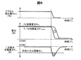
図6は、比較例1の燃料電池車両の状態を例示したタイミングチャートである。図6には、アクセル踏込量DACCと、FC発電電力PFCと、T/M消費電力PCONSと、二次電池140の入力(充電)電力Pinと、許容入力上限値Winとの時系列変化が例示されている。比較例1の燃料電池車両は、上限要求電力PMAXの算出をおこなわない点以外は本実施形態の燃料電池車両10と同じである。この場合、アクセルOFF等によってT/M消費電力PCONSが減少すると、車両要求電力PVHCLに含まれるPT/M+PAUXが減少し、これにともなってFC発電電力PFCが減少する。しかし、T/M消費電力PCONSの急減時には、FC発電電力PFCがこのT/M消費電力PCONSの急減に対応するまでに時間的な遅れがあるため、その間に発電された電力の過剰分は二次電池に充電され、二次電池において過充電が発生する場合がある。また、二次電池140に供給される入力(充電)電力Pinが許容入力上限値Winを上回ることがある。一方、本実施形態によれば、T/M消費電力PCONSが急減する場合には、車両要求電力PVHCLに含まれるPT/M+PAUXが減少するほか、許容充電電力α・PWinがゼロになるため、FC発電電力PFCを速やかに低減させることができる。これにより、過剰な電力の発生は抑制され、二次電池140の過充電を抑制できる。また、二次電池140に供給される充電電力Pinが許容入力上限値Winを上回ることを抑制できる。
FIG. 6 is a timing chart illustrating the state of the fuel cell vehicle of Comparative Example 1. 6 shows, the accelerator depression amount D ACC, and FC generated power P FC, the T / M power P CONS, input (charge) and the power P in of the
図7は、比較例2の燃料電池車両の状態を例示したタイミングチャートである。図7には、二次電池の蓄電量(SOC)と、FC発電電力PFCと、車両要求電力PVHCLと、燃料電池の発電電圧と、FC捕機の消費電力の時系列変化が例示されている。比較例2の燃料電池車両は、上限要求電力PMAXの算出をおこなわない点、および、車両要求電力PVHCLをPT/M+PAUX+Pchgから算出する点以外は本実施形態の燃料電池車両10と同じである。車両要求電力PVHCLをPT/M+PAUX+Pchgから算出した場合、間欠運転時には、高電位回避電圧を発生させるための発電電力が車両要求電力PVHCLよりも大きくなる場合がある。この場合、FC発電電力PFCが車両要求電力PVHCLよりも大きくなる。FC発電電力PFCが車両要求電力PVHCLよりも大きくなることで発電電力の過剰分が二次電池に充電され、二次電池において過充電が発生する場合がある。一方、本実施形態の車両要求電力PVHCLは、PT/M+PAUX+Pchgと、POCのうちの大きい方となるように構成されている。これにより、FC発電電力PFCが車両要求電力PVHCLよりも大きくなる状態の発生を抑制できる。
FIG. 7 is a timing chart illustrating the state of the fuel cell vehicle of Comparative Example 2. FIG. 7 exemplifies time-series changes in the storage amount (SOC) of the secondary battery, the FC generated power P FC , the vehicle required power P VLCL , the power generation voltage of the fuel cell, and the power consumption of the FC catcher. ing. The fuel cell vehicle of Comparative Example 2 is the fuel cell vehicle of the present embodiment except that the upper limit required power P MAX is not calculated and the vehicle required power P VLCL is calculated from P T / M + P AUX +
また、比較例2において、FC捕機の要求電力を定数として設定している場合には、FC捕機の実消費が要求電力よりも小さくなることがあり、この場合、発電電力の余剰分が二次電池に充電され、二次電池において過充電が発生することがある。一方、本実施形態によれば、FC捕機の要求電力を定数として設定していても、上限要求電力P MAX に含まれる許容充電電力α・PWinが二次電池の蓄電量(SOC)の増加に応じて減少するため、FC発電電力PFCが抑制されて二次電池における過充電の発生が抑制される。 Moreover, in the comparative example 2, when the required power of the FC catcher is set as a constant, the actual consumption of the FC catcher may be smaller than the required power. In this case, the surplus of the generated power is The secondary battery is charged, and overcharge may occur in the secondary battery. On the other hand, according to the present embodiment, even if the required power of the FC catcher is set as a constant, the allowable charge power α · P Win included in the upper limit required power P MAX is equal to the charged amount (SOC) of the secondary battery. to reduce in accordance with the increase, occurrence of overcharge in the secondary battery is FC generated power P FC is suppressed is suppressed.
以上説明した、本実施形態の燃料電池車両10によれば、T/M消費電力PCONSが急減するときには、二次電池140の許容充電電力α・P Win がゼロになって上限要求電力PMAXが減少するため、FC発電電力PFCを速やかに低減させることができる。これにより、T/M消費電力PCONSの急減時における、二次電池140の過充電の発生を低減させることができる。また、本実施形態の上限要求電力PMAXは、二次電池140の温度および蓄電量(SOC)による許容入力上限値Winと補正係数との積である許容充電電力α・PWinを含んでいる。よって、二次電池140の温度や蓄電量(SOC)によって許容入力上限値Winが減少している場合には、それにともなって車両要求電力PVHCLを減少させることができる。これにより、FC発電電力PFCが抑制されて二次電池140における過充電の発生を低減させることができる。
According to the
B.第2実施形態:
図8は、第2実施形態の燃料電池車両10Aの状態を例示したタイミングチャートある。図8には、燃料電池車両10Aのシフトポジションと、補正係数αと、上限要求電力PMAXと、車両要求電力PVHCLと、FC発電電力PFCと、ACP駆動要求電力PRQとの時系列変化が例示されている。第2実施形態の燃料電池車両10Aは、補正係数設定制御(図3)のステップS110における「予め設定されている条件」の内容が異なる点以外は第1実施形態の燃料電池車両10と同じである。第2実施形態の燃料電池車両10Aは、「予め設定されている条件」として、シフトポジションがD(ドライブ)からN(ニュートラル)に切り替えられ、かつ、FC発電電力PFCがWin保護設定電力PPRO以上となること、または、これらの状態となった後予め設定された時間内であることが設定されている。Win保護設定電力PPROは、第1実施形態と同様に、二次電池140を保護するために二次電池140に最低限供給すべき電力の値である。本実施形態の「Win保護設定電力PPRO」は、特許請求の範囲の「第2の閾値」に該当する。
B. Second embodiment:
FIG. 8 is a timing chart illustrating the state of the fuel cell vehicle 10A of the second embodiment. 8 includes a shift position of the fuel cell vehicle 10 A, and the correction coefficient alpha, and the upper limit required power P MAX, and vehicle request power P VHCL, and FC generated power P FC, when the ACP required driving power P RQ A series change is illustrated. The fuel cell vehicle 10A of the second embodiment is the same as the
燃料電池車両10AのシフトポジションがD(ドライブ)からN(ニュートラル)に切り替えられた場合、T/M消費電力PCONSが急減する。この場合であっても、二次電池140の許容充電電力α・P Win がゼロになって上限要求電力PMAXが減少するため、FC発電電力PFCを速やかに低減させることができる。これにより、T/M消費電力PCONSの急減時における、二次電池140の過充電の発生を低減させることができる。
If the shift position of the fuel cell vehicle 10 A is switched from the D (drive) to N (neutral), T / M power P CONS rapidly decreases. Even in this case, the allowable charging power α · P Win of the
C.第3実施形態:
図9は、第3実施形態の補正係数設定制御を説明するためのフローチャートである。第3実施形態の補正係数設定制御は、第1実施形態の補正係数設定制御(図3)と比較して、ステップS110、S115、S125、S135が異なり、それ以外(ステップS120、S140、S150、S160)は同じである。第3実施形態のステップS110では、「予め設定されている条件」として、ブレーキによる燃料電池車両10Bの制動力Fbがトラクションモーター136による燃料電池車両10Bのタイヤの駆動力Fdよりも大きくなること(Fb>Fd)、が設定されている。燃料電池車両10Bの制動力Fbは、運転者によるブレーキの踏み込み量(ブレーキ踏込量DBR)[%]から算出することができる。ブレーキ踏込量DBRは、例えば、燃料電池車両10Bがブレーキ位置検出部を備えることによって検出できる。このブレーキ位置検出部は、検出したブレーキ踏込量DBRを制御装置180に送信してもよい。燃料電池車両10Bの駆動力Fdは、例えば、アクセル踏込量DACCと、トラクションモーター136の回転数とから算出することができる。制動力Fbが駆動力Fdよりも大きくなった場合(Fb>Fd)とは、例えば、運転者が燃料電池車両10Bの加速中にブレーキを踏んだときに生じ得る。この場合、燃料電池車両10Bでは、燃料電池110の発電中にトラクションモーター136の回転数が急減し、トラクションモーター136の消費電力(T/M消費電力PCONS)が急減する。
C. Third embodiment:
FIG. 9 is a flowchart for explaining correction coefficient setting control according to the third embodiment. The correction coefficient setting control of the third embodiment is different from the correction coefficient setting control (FIG. 3) of the first embodiment in steps S110, S115, S125, and S135, and the others (steps S120, S140, S150, S160) is the same. In step S110 of the third embodiment, as a “predetermined condition”, the braking force Fb of the fuel cell vehicle 10B by the brake is greater than the driving force Fd of the tire of the fuel cell vehicle 10B by the traction motor 136 ( Fb> Fd) is set. The braking force Fb of the fuel cell vehicle 10B can be calculated from the brake depression amount (brake depression amount D BR ) [%] by the driver. Brake depression amount D BR, for example, a fuel cell vehicle 10B can be detected by providing a braking position detection unit. The brake position detection unit may transmit the detected brake depression amount DBR to the
PM−ECU181は、制動力Fbが駆動力Fdよりも大きい状態(Fb>Fd)であると判定すると、ロック予測フラグをONにする(ステップS125)。一方、制動力Fbが駆動力Fd以下の状態(Fb≦Fd)であると判定すると、ロック予測フラグをOFFにする(ステップS115)。ロック予測フラグは、トラクションモーター136においてモータロックが発生する可能性がある状態か否かを示す。制動力Fbが駆動力Fdよりも大きくなった場合には、トラクションモーター136においてモータロックが発生しやすい状態と考えられるため、このフラグが立てられる。ステップS135では、PM−ECU181は、ロック予測フラグ、二次電池140の温度Tbaおよび蓄電量(SOC)に基づいて補正係数αの算出をおこなう。また、PM−ECU181は、上限要求電力PMAXおよび車両要求電力PVHCLの算出をおこなう。
When determining that the braking force Fb is greater than the driving force Fd (Fb> Fd), the PM-ECU 181 turns on the lock prediction flag (step S125). On the other hand, if it is determined that the braking force Fb is equal to or less than the driving force Fd (Fb ≦ Fd), the lock prediction flag is turned OFF (step S115). The lock prediction flag indicates whether or not there is a possibility that motor lock may occur in the
図10は、第3実施形態における補正係数αと二次電池140の温度Tbaおよび蓄電量(SOC)との関係を例示した説明図である。図10には、二次電池140の温度(例えば、T1、T2、T3)[℃]ごとの蓄電量(SOC)と補正係数αとの関係が、ロック予測フラグがONの場合とOFFの場合とについて、それぞれ示されている。図10に示すように、補正係数αは、二次電池140の温度および蓄電量が同じ場合には、ロック予測フラグがONの場合の補正係数αは、OFFの場合よりも値が小さくなるように設定されている。すなわち、ロック予測フラグがONのとき、補正係数αが相対的に減少するように構成されている。なお、ロック予測フラグがOFFのときの補正係数αの値は、第1実施形態の図4と同じであることが好ましい。
FIG. 10 is an explanatory diagram illustrating the relationship between the correction coefficient α, the temperature Tba of the
図11は、第3実施形態の燃料電池車両10Bの状態を例示したタイミングチャートである。図11には、燃料電池車両10Bの駆動力Fdと、制動力Fbと、ロック予測フラグと、補正係数αと、上限要求電力PMAXと、車両要求電力PVHCLと、FC発電電力PFCと、ACP駆動要求電力PRQとの時系列変化が例示されている。ここでは、T1時点において運転者がアクセルを緩めるとともにブレーキの踏み込みを開始し、T2時点において制動力Fbが駆動力Fdよりも大きくなり、T3時点において車両が停止したものとして説明する。T2時点において、ロック予測フラグがONになり、補正係数αが減少し、上限要求電力PMAXが減少する。上限要求電力PMAXにはα・PWinが含まれているためである(上記式(2)参照)。これにより、実際にモータロックが発生する前に、FC発電電力PFCを絞り始めることができ、二次電池140の過充電を抑制できる。
FIG. 11 is a timing chart illustrating the state of the fuel cell vehicle 10B of the third embodiment. In FIG. 11, the driving force Fd, the braking force Fb, the lock prediction flag, the correction coefficient α, the upper limit required power P MAX , the vehicle required power P VHCL, and the FC generated power P FC of the fuel cell vehicle 10B A time-series change with the ACP drive required power PRQ is illustrated. Here, it is assumed that the driver releases the accelerator and starts to depress the brake at time T1, the braking force Fb becomes larger than the driving force Fd at time T2, and the vehicle stops at time T3. At time T2, the lock prediction flag is turned ON, the correction coefficient α is decreased, and the upper limit required power P MAX is decreased. This is because the upper limit required power P MAX includes α · P Win (see the above formula (2)). Thereby, before the motor lock actually occurs, the FC generated power P FC can be started to be reduced, and the overcharge of the
以上説明した、本実施形態の燃料電池車両10Bによっても、T/M消費電力PCONSが急減するときには、上限要求電力PMAXが減少するため、FC発電電力PFCを速やかに低減させることができる。これにより、T/M消費電力PCONSの急減時における、二次電池140の過充電の発生を低減させることができる。従来から、燃料電池車両の加速中にブレーキを踏むと、トラクションモーター136の回転数が急減して、発電の余剰電力による二次電池140の過充電が発生することがあった。これは、T/M消費電力PCONSの急減時には、通信の遅れ等により、車両要求電力PVHCL(指令電力PCOM)の減少が遅れるためである。本実施形態によれば、制動力Fbが駆動力Fdよりも大きくなったときに、制動力Fbが駆動力Fd以下の場合よりも、上限要求電力PMAXを減少させるため、FC発電電力PFCを速やかに低減させることができる。これにより、T/M消費電力PCONSの急減時における、二次電池140の過充電の発生を低減させることができる。
Also with the fuel cell vehicle 10B of the present embodiment described above, when the T / M power consumption P CONS decreases rapidly, the upper limit required power P MAX decreases, so that the FC generated power P FC can be quickly reduced. . This can reduce the occurrence of overcharge of the
D.第4実施形態:
図12は、第4実施形態の補正係数設定制御を説明するためのフローチャートである。第4実施形態の補正係数設定制御は、第3実施形態の補正係数設定制御(図9)と比較して、ステップS127が追加されている点が異なる。ステップS127では、PM−ECU181は、アクセル踏込量DACCが閾値ThACCよりも大きいか否かの判定をおこなう。ここでは、閾値ThACCとして10[%]が設定されている。閾値ThACCは、10[%]以外の数値であってもよい。アクセル踏込量DACCが閾値ThACC以下の場合(ステップS127:No)、ロック予測フラグがONにも関わらず、補正係数αをロック予測フラグOFF時の値(図10)とする。すなわち、アクセル踏込量DACCが閾値ThACC以下の場合には、ロック予測に基づいて補正係数αを減少させない。アクセル踏込量DACCが値ThACC以下の場合には、上限要求電力PMAXが高電位回避電圧を発生させるための発電電力よりも小さくなるおそれがある。そのため、この場合には、ロック予測フラグがONであっても、補正係数αを減少させないようにすることによって、高電位回避電圧を発生させることができる。なお、他の実施例として、アクセル踏込量DACCが閾値ThACC以下の場合には、補正係数αの値を図10において、ロック予測フラグOFF時の値よりも小さく、ロック予測フラグがONの時よりも大きい値にしてもよい。この場合、高電位回避をおこないつつ、二次電池140の過充電の発生を抑制できる。
D. Fourth embodiment:
FIG. 12 is a flowchart for explaining correction coefficient setting control according to the fourth embodiment. The correction coefficient setting control of the fourth embodiment is different from the correction coefficient setting control (FIG. 9) of the third embodiment in that step S127 is added. In step S127, PM-ECU 181 determines whether or not accelerator depression amount D ACC is greater than threshold value Th ACC . Here, 10 [%] is set as the threshold Th ACC . The threshold value Th ACC may be a numerical value other than 10 [%]. When the accelerator depression amount D ACC is equal to or less than the threshold value Th ACC (step S127: No), the correction coefficient α is set to the value when the lock prediction flag is OFF (FIG. 10) regardless of whether the lock prediction flag is ON. That is, when the accelerator depression amount D ACC is equal to or smaller than the threshold Th ACC , the correction coefficient α is not decreased based on the lock prediction. When the accelerator depression amount D ACC is equal to or less than the value Th ACC , the upper limit required power P MAX may be smaller than the generated power for generating the high potential avoidance voltage. Therefore, in this case, even if the lock prediction flag is ON, the high potential avoidance voltage can be generated by not reducing the correction coefficient α. As another example, when the accelerator depression amount D ACC is equal to or smaller than the threshold Th ACC , the value of the correction coefficient α in FIG. 10 is smaller than the value when the lock prediction flag is OFF, and the lock prediction flag is ON. You may make it a value larger than time. In this case, the occurrence of overcharge of the
図13は、第4実施形態の燃料電池車両10Cの状態を例示したタイミングチャートである。図13には、アクセル踏込量DACCと、駆動力Fdと、制動力Fbと、ロック予測フラグと、補正係数αと、上限要求電力PMAXとの時系列変化が例示されている。ここでは、アクセル踏込量DACCが閾値ThACCよりも小さく、T1時点において運転者がアクセルを緩めるとともにブレーキの踏み込みを開始し、T2時点において制動力Fbが駆動力Fdよりも大きくなったものとして説明する。T2時点において、ロック予測フラグがONになるが、補正係数αが減少しない。そのため、上限要求電力PMAXは、値が減少しない。これにより、上限要求電力PMAXが高電位回避電圧を発生させるための発電電力よりも小さくなることを抑制できる。 FIG. 13 is a timing chart illustrating the state of the fuel cell vehicle 10C of the fourth embodiment. FIG. 13 illustrates time-series changes in the accelerator depression amount D ACC , the driving force Fd, the braking force Fb, the lock prediction flag, the correction coefficient α, and the upper limit required power P MAX . Here, it is assumed that the accelerator depression amount D ACC is smaller than the threshold Th ACC , the driver loosens the accelerator and starts to depress the brake at time T1, and the braking force Fb becomes larger than the driving force Fd at time T2. explain. At time T2, the lock prediction flag is turned on, but the correction coefficient α does not decrease. Therefore, the value of the upper limit required power P MAX does not decrease. Thus, it is possible to suppress the upper limit required power P MAX is smaller than the generated electric power for generating the high-potential avoidance voltage.
E.第5実施形態:
図14は、第5実施形態の補正係数設定制御を説明するためのフローチャートである。第5実施形態の補正係数設定制御は、第4実施形態の補正係数設定制御(図12)と比較して、ステップS127の位置がステップS125の上流側にある点が異なる。この構成の場合、「予め設定されている条件」を満たしていても(ステップS110:Yes)、アクセル踏込量DACCが閾値ThACC以下の場合(ステップS127:No)には、ロック予測フラグがONにならない。この場合であっても、アクセル踏込量DACCが閾値ThACC以下の場合には、補正係数αが減少しないため、高電位回避電圧を発生させることができる。
E. Fifth embodiment:
FIG. 14 is a flowchart for explaining correction coefficient setting control according to the fifth embodiment. The correction coefficient setting control of the fifth embodiment is different from the correction coefficient setting control (FIG. 12) of the fourth embodiment in that the position of step S127 is on the upstream side of step S125. In the case of this configuration, even when the “predetermined condition” is satisfied (step S110: Yes), when the accelerator depression amount D ACC is equal to or smaller than the threshold Th ACC (step S127: No), the lock prediction flag is set. Does not turn on. Even in this case, when the accelerator depression amount D ACC is equal to or smaller than the threshold value Th ACC , the correction coefficient α does not decrease, so that a high potential avoidance voltage can be generated.
F.変形例:
なお、この発明は上記の実施形態に限られるものではなく、その要旨を逸脱しない範囲において種々の態様において実施することが可能であり、例えば次のような変形も可能である。
F. Variations:
The present invention is not limited to the above-described type state, that without departing from the spirit and scope may be reduced to practice in various embodiments, it is also possible for example, the following modifications.
F−1.変形例1:
本実施形態では、ACP駆動要求電力PRQは、ACP138をアクセル要求トルクTACCに対応する駆動状態とするために必要な電力であるとした。しかし、ACP駆動要求電力PRQには、バルブの駆動電力などACP138の駆動電力以外の電力が含まれていてもよい。
F-1. Modification 1:
In the present embodiment, ACP required driving power P RQ was that the power necessary for the driving state corresponding to ACP138 the accelerator demanded torque T ACC. However, ACP to the required driving power P RQ, may include power other than the driving power of ACP138 a driving power of the valve.
F−2.変形例2:
本実施形態では、PM−ECU181は、車両要求電力PVHCL(指令電力PCOM)と上限要求電力PMAXとの比較をおこない、車両要求電力PVHCLが上限要求電力PMAXを上回っていないか否かを判定するとした。しかし、PM−ECU181は、車両要求電力PVHCLと上限要求電力PMAXとを比較せずに、これらをパワー指令PCOMとしてFDC―ECU183に発行し、FDC―ECU183が車両要求電力PVHCLと上限要求電力PMAXとを比較してもよい。また、PM−ECU181とFDC―ECU183のそれぞれが車両要求電力PVHCLと上限要求電力PMAXとを比較してもよい。
F-2. Modification 2:
In the present embodiment, the PM-ECU 181 compares the vehicle required power P VHCL (command power P COM ) with the upper limit required power P MAX and determines whether or not the vehicle required power P VHCL exceeds the upper limit required power P MAX. Judgment was made. However, the PM-ECU 181 issues the power command PCOM as a power command PCOM to the FDC-
F−3.変形例3:
第1実施形態および第2実施形態の補正係数設定制御(図3)では、ステップS110において「予め設定されている条件」を満たしていると判定された場合、補正係数αをゼロにする(ステップS130)ものとして説明した。しかし、「予め設定されている条件」を満たしている場合に、補正係数αをゼロにするのではなく、第3実施形態のように、「予め設定されている条件」を満たしていない場合よりもαの値を小さくするように構成してもよい。この場合であっても、「予め設定されている条件」を満たしているときに上限要求電力PMAXを減少させることがきるため、二次電池140の過充電の発生を低減できる。一方、第3実施形態において、「予め設定されている条件」を満たしていると判定された場合に、補正係数αをゼロにするように構成してもよい。
F-3. Modification 3:
In the correction coefficient setting control (FIG. 3) of the first embodiment and the second embodiment, if it is determined in step S110 that the “preset condition” is satisfied, the correction coefficient α is set to zero (step S130). However, when the “predetermined condition” is satisfied, the correction coefficient α is not set to zero, but when the “predetermined condition” is not satisfied as in the third embodiment. Also, the value of α may be reduced. Even in this case, the upper limit required power P MAX can be reduced when the “predetermined condition” is satisfied, so that the occurrence of overcharge of the
F−4.変形例4:
第4実施形態の補正係数設定制御(図12)では、アクセル踏込量DACCが閾値ThACC以下の場合(ステップS127:No)には、ロック予測に基づいて補正係数αを減少させないものとして説明した。しかし、アクセル踏込量DACCが閾値ThACC以下の場合であっても、ロック予測に基づいて、補正係数αを減少させてもよい。このときの補正係数αは、アクセル踏込量DACCが閾値ThACCよりも大きいときの補正係数α(図10の「ロック予測フラグON時」)よりも値が大きくなることが好ましい。これにより、高電位回避をおこないつつ、二次電池140の過充電の発生を抑制できる。
F-4. Modification 4:
In the correction coefficient setting control (FIG. 12) of the fourth embodiment, when the accelerator depression amount D ACC is equal to or smaller than the threshold Th ACC (step S127: No), it is assumed that the correction coefficient α is not decreased based on the lock prediction. did. However, even when the accelerator depression amount D ACC is equal to or smaller than the threshold Th ACC , the correction coefficient α may be decreased based on the lock prediction. The correction coefficient α at this time is preferably larger than the correction coefficient α when the accelerator depression amount D ACC is larger than the threshold Th ACC (“when the lock prediction flag is ON” in FIG. 10). Thereby, generation | occurrence | production of the overcharge of the
F−5.変形例5:
本発明の一実施形態において、制御装置180は、T/M消費電力PCONSが急減する条件として予め設定されている条件を満たしたか否かを判定し、その条件を満たしていると判定した場合に、二次電池140の温度および蓄電量に基づいて算出された充電電力Pchgをゼロにして車両要求電力PVHCLをPT/M+PAUX+Pchgから算出し、その条件を満たしていないと判定した場合に、二次電池140の温度および蓄電量に基づいて算出された充電電力Pchgを用いてPT/M+PAUX+Pchgから車両要求電力PVHCLを算出してもよい。こうすることによっても、T/M消費電力PCONSが急減するときには、車両要求電力PVHCLに含まれる充電電力Pchgがゼロになって車両要求電力PVHCLが減少するため、二次電池140の過充電の発生を抑制できる。
F-5. Modification 5:
In one embodiment of the present invention, the
10…燃料電池車両
100…燃料電池システム
110…燃料電池
120…FC昇圧コンバーター
130…パワーコントロールユニット
132…モータードライバー
136…トラクションモーター
138…エアコンプレッサー
139…車速検出部
140…二次電池
142…SOC検出部
150…FC補機
180…制御装置
190…アクセル位置検出部
WL…車輪
DESCRIPTION OF
Claims (11)
前記車両を駆動するモーターに電力を供給する燃料電池と、
前記モーターに電力を供給する二次電池と、
前記二次電池の温度および蓄電量を検出するSOC検出部と、
前記車両のアクセル踏込量を検出するアクセル位置検出部と、
前記燃料電池の発電電力を制御する制御部と、を備え、
前記制御部は、
前記アクセル踏込量と、前記二次電池の温度を用いて検出された前記二次電池の蓄電量とに基づいて、前記燃料電池に指令される発電要求電力を算出する発電要求電力算出部と、
前記アクセル踏込量と、前記二次電池の温度および蓄電量とに基づいて、前記燃料電池が発電可能な上限要求電力を算出する上限要求電力算出部と、を備え、
前記上限要求電力には、前記二次電池の温度および蓄電量に基づいて算出された許容充電電力が含まれており、
前記制御部は、
前記モーターの消費電力が急減する条件として予め設定されている条件を満たしたか否かを判定し、
前記条件を満たしていると判定すると、前記許容充電電力をゼロにして前記上限要求電力を算出し、
前記条件を満たしていないと判定すると、前記二次電池の温度および蓄電量に基づいて算出された許容充電電力を用いて前記上限要求電力を算出し、
算出した前記発電要求電力が算出した前記上限要求電力を上回る場合、前記燃料電池に対して、算出した前記上限要求電力に対応した発電を実行させる、
燃料電池システム。 A fuel cell system mounted on a vehicle,
A fuel cell that supplies power to a motor that drives the vehicle;
A secondary battery for supplying power to the motor;
An SOC detection unit for detecting a temperature and a storage amount of the secondary battery;
An accelerator position detector for detecting an accelerator depression amount of the vehicle;
A control unit for controlling the generated power of the fuel cell,
The controller is
Based on the accelerator depression amount and the storage amount of the secondary battery detected using the temperature of the secondary battery, a required generation power calculation unit that calculates the required generation power commanded to the fuel cell;
An upper limit required power calculation unit that calculates an upper limit required power that can be generated by the fuel cell, based on the accelerator depression amount, the temperature of the secondary battery, and the storage amount;
The upper limit required power includes an allowable charging power calculated based on a temperature and a storage amount of the secondary battery,
The controller is
It is determined whether or not a condition set in advance as a condition for rapidly reducing the power consumption of the motor is satisfied,
If it is determined that the condition is satisfied, the upper limit required power is calculated by setting the allowable charging power to zero,
When it is determined that the condition is not satisfied, the upper limit required power is calculated using the allowable charging power calculated based on the temperature and the amount of power stored in the secondary battery,
When the calculated power generation required power exceeds the calculated upper limit required power, the fuel cell is caused to execute power generation corresponding to the calculated upper limit required power.
Fuel cell system.
前記予め設定されている条件は、前記アクセル踏込量の減少速度が第1の閾値以上となることである、燃料電池システム。 The fuel cell system according to claim 1,
The fuel cell system in which the preset condition is that a decrease rate of the accelerator depression amount is equal to or greater than a first threshold value.
前記予め設定されている条件は、前記車両のシフトポジションがドライブからニュートラルに切り替えられ、かつ、前記燃料電池の発電電力が第2の閾値以上となることである、燃料電池システム。 The fuel cell system according to claim 1,
The preset condition is a fuel cell system in which the shift position of the vehicle is switched from drive to neutral, and the generated power of the fuel cell is equal to or greater than a second threshold value.
前記車両を駆動するモーターに電力を供給する燃料電池と、
前記モーターに電力を供給する二次電池と、
前記二次電池の温度および蓄電量を検出するSOC検出部と、
前記車両のアクセル踏込量を検出するアクセル位置検出部と、
前記アクセル踏込量と、前記二次電池の温度を用いて検出された前記二次電池の蓄電量とに基づいて、前記燃料電池に指令される発電要求電力を算出する制御部と、を備え、
前記発電要求電力には、前記二次電池の温度および蓄電量に応じて算出される充電電力が含まれており、
前記制御部は、
前記モーターの消費電力が急減する条件として予め設定されている条件を満たしたか否かを判定し、
前記条件を満たしていると判定すると、前記二次電池の温度および蓄電量に基づいて算出された充電電力をゼロにして前記発電要求電力を算出し、
前記条件を満たしていないと判定すると、前記二次電池の温度および蓄電量に基づいて算出された充電電力を用いて前記発電要求電力を算出する、
燃料電池システム。 A fuel cell system mounted on a vehicle,
A fuel cell that supplies power to a motor that drives the vehicle;
A secondary battery for supplying power to the motor;
An SOC detection unit for detecting a temperature and a storage amount of the secondary battery;
An accelerator position detector for detecting an accelerator depression amount of the vehicle;
A control unit that calculates the required power generation to be commanded to the fuel cell based on the accelerator depression amount and the storage amount of the secondary battery detected using the temperature of the secondary battery ;
The power generation required power includes charging power calculated according to the temperature and the amount of electricity stored in the secondary battery,
The controller is
It is determined whether or not a condition set in advance as a condition for rapidly reducing the power consumption of the motor is satisfied,
When it is determined that the condition is satisfied, the power generation required power is calculated by setting the charging power calculated based on the temperature and the storage amount of the secondary battery to zero,
When it is determined that the condition is not satisfied, the power generation required power is calculated using the charging power calculated based on the temperature and the amount of power stored in the secondary battery.
Fuel cell system.
前記予め設定されている条件は、前記アクセル踏込量の減少速度が第1の閾値以上となることである、燃料電池システム。 The fuel cell system according to claim 4, wherein
The fuel cell system in which the preset condition is that a decrease rate of the accelerator depression amount is equal to or greater than a first threshold value.
前記予め設定されている条件は、前記車両のシフトポジションがドライブからニュートラルに切り替えられ、かつ、前記燃料電池の発電電力が第2の閾値以上となることである、燃料電池システム。 The fuel cell system according to claim 4, wherein
The preset condition is a fuel cell system in which the shift position of the vehicle is switched from drive to neutral, and the generated power of the fuel cell is equal to or greater than a second threshold value.
請求項1から請求項6までのいずれか一項に記載の燃料電池システムと、
前記燃料電池システムから供給される電力によって前記車両を駆動させるモーターと、を備える車両。 A vehicle,
A fuel cell system according to any one of claims 1 to 6,
And a motor that drives the vehicle with electric power supplied from the fuel cell system.
前記燃料電池システムは、前記車両を駆動するモーターに電力を供給する燃料電池と、前記モーターに電力を供給する二次電池とを含んでおり、
前記制御方法は、
前記車両のアクセル踏込量と、前記二次電池の温度とを検出して、前記アクセル踏込量と、前記二次電池の温度を用いて検出した前記二次電池の蓄電量とに基づいて、前記燃料電池に指令される発電要求電力を算出し、
前記アクセル踏込量と、前記二次電池の温度および蓄電量とに基づいて、前記燃料電池が発電可能な上限要求電力を算出し、前記上限要求電力には、前記二次電池の温度および蓄電量に基づいて算出された許容充電電力が含まれており、
前記モーターの消費電力が急減する条件として予め設定されている条件を満たしたか否かを判定し、
前記条件を満たしていると判定すると、前記許容充電電力をゼロにして前記上限要求電力を算出し、
前記条件を満たしていないと判定すると、前記二次電池の温度および蓄電量に基づいて算出された許容充電電力を用いて前記上限要求電力を算出し、
算出した前記発電要求電力が算出した前記上限要求電力を上回る場合、前記燃料電池に対して、算出した前記上限要求電力に対応した発電を実行させる、制御方法。 A control method for a fuel cell system mounted on a vehicle,
The fuel cell system includes a fuel cell that supplies electric power to a motor that drives the vehicle, and a secondary battery that supplies electric power to the motor,
The control method is:
An accelerator depression amount of the vehicle, by detecting the temperature of the secondary battery, and the accelerator depression amount, based on the storage amount of the secondary battery detected by using the temperature of the secondary battery, Calculate power generation required power commanded to the fuel cell,
Based on the accelerator depression amount and the temperature and storage amount of the secondary battery, an upper limit required power that can be generated by the fuel cell is calculated, and the upper limit required power includes the temperature and storage amount of the secondary battery. The allowable charging power calculated based on
It is determined whether or not a condition set in advance as a condition for rapidly reducing the power consumption of the motor is satisfied,
If it is determined that the condition is satisfied, the upper limit required power is calculated by setting the allowable charging power to zero,
When it is determined that the condition is not satisfied, the upper limit required power is calculated using the allowable charging power calculated based on the temperature and the charged amount of the secondary battery,
A control method of causing the fuel cell to perform power generation corresponding to the calculated upper limit required power when the calculated required power generation exceeds the calculated upper limit required power.
前記車両を駆動するモーターに電力を供給する燃料電池と、
前記モーターに電力を供給する二次電池と、
前記二次電池の温度および蓄電量を検出するSOC検出部と、
前記車両のアクセル踏込量を検出するアクセル位置検出部と、
前記燃料電池の発電電力を制御する制御部と、を備え、
前記制御部は、
前記アクセル踏込量と、前記二次電池の温度を用いて検出された前記二次電池の蓄電量とに基づいて、前記燃料電池に指令される発電要求電力を算出する発電要求電力算出部と、
前記アクセル踏込量と、前記二次電池の温度および蓄電量とに基づいて、前記燃料電池が発電可能な上限要求電力を算出する上限要求電力算出部と、を備え、
前記上限要求電力には、前記二次電池の温度および蓄電量と、補正係数とに基づいて算出された許容充電電力が含まれており、
前記制御部は、
前記モーターの消費電力が急減する条件として予め設定されている条件を満たしたか否かを判定し、
前記条件を満たしていると判定すると、前記条件を満たしていない場合よりも前記補正係数を低減させることにより前記許容充電電力を低減させて前記上限要求電力を算出し、
前記条件を満たしていないと判定すると、前記条件を満たしている場合よりも前記補正係数を大きくすることにより前記許容充電電力を増加させて前記上限要求電力を算出し、
算出した前記発電要求電力が算出した前記上限要求電力を上回る場合、前記燃料電池に対して、算出した前記上限要求電力に対応した発電を実行させる、
燃料電池システム。 A fuel cell system mounted on a vehicle,
A fuel cell that supplies power to a motor that drives the vehicle;
A secondary battery for supplying power to the motor;
An SOC detection unit for detecting a temperature and a storage amount of the secondary battery;
An accelerator position detector for detecting an accelerator depression amount of the vehicle;
A control unit for controlling the generated power of the fuel cell,
The controller is
Based on the accelerator depression amount and the storage amount of the secondary battery detected using the temperature of the secondary battery, a required generation power calculation unit that calculates the required generation power commanded to the fuel cell;
An upper limit required power calculation unit that calculates an upper limit required power that can be generated by the fuel cell, based on the accelerator depression amount, the temperature of the secondary battery, and the storage amount;
The upper limit required power includes an allowable charging power calculated based on a temperature and a storage amount of the secondary battery, and a correction coefficient,
The controller is
It is determined whether or not a condition set in advance as a condition for rapidly reducing the power consumption of the motor is satisfied,
When it is determined that the condition is satisfied, the upper limit required power is calculated by reducing the allowable charging power by reducing the correction coefficient than when the condition is not satisfied,
When it is determined that the condition is not satisfied, the upper limit required power is calculated by increasing the allowable charging power by increasing the correction coefficient than when the condition is satisfied,
When the calculated power generation required power exceeds the calculated upper limit required power, the fuel cell is caused to execute power generation corresponding to the calculated upper limit required power.
Fuel cell system.
前記予め設定されている条件は、ブレーキによる前記車両の制動力が前記モーターによる前記車両の駆動力よりも大きくなることである、燃料電池システム。 The fuel cell system according to claim 9, wherein
The preset condition is that the braking force of the vehicle by a brake is larger than the driving force of the vehicle by the motor.
前記制御部は、前記条件を満たしていると判定したときにおいて、前記アクセル踏込量が予め設定された値以下の場合には、前記アクセル踏込量が前記予め設定された値よりも大きい場合よりも前記補正係数を大きくする、燃料電池システム。 The fuel cell system according to claim 10, wherein
When the control unit determines that the condition is satisfied and the accelerator depression amount is equal to or smaller than a preset value, the accelerator depression amount is larger than the preset value. A fuel cell system in which the correction coefficient is increased.
Priority Applications (6)
| Application Number | Priority Date | Filing Date | Title |
|---|---|---|---|
| US14/926,254 US9776526B2 (en) | 2014-11-14 | 2015-10-29 | Fuel cell system, fuel cell vehicle, and method of controlling fuel cell system |
| CA2911062A CA2911062C (en) | 2014-11-14 | 2015-11-03 | Fuel cell system, fuel cell vehicle, and method of controlling fuel cell system |
| KR1020150155015A KR101805986B1 (en) | 2014-11-14 | 2015-11-05 | Fuel cell system, fuel cell vehicle, and method of controlling fuel cell system |
| DE102015119266.7A DE102015119266B9 (en) | 2014-11-14 | 2015-11-09 | Fuel cell system, fuel cell vehicle and method for controlling a fuel cell system |
| CN201510770703.7A CN105633437B (en) | 2014-11-14 | 2015-11-12 | The control method of fuel cell system, fuel-cell vehicle and fuel cell system |
| US15/647,434 US9873351B2 (en) | 2014-11-14 | 2017-07-12 | Fuel cell system, fuel cell vehicle, and method of controlling fuel cell system |
Applications Claiming Priority (2)
| Application Number | Priority Date | Filing Date | Title |
|---|---|---|---|
| JP2014231646 | 2014-11-14 | ||
| JP2014231646 | 2014-11-14 |
Publications (3)
| Publication Number | Publication Date |
|---|---|
| JP2016103460A JP2016103460A (en) | 2016-06-02 |
| JP2016103460A5 JP2016103460A5 (en) | 2017-01-05 |
| JP6278000B2 true JP6278000B2 (en) | 2018-02-14 |
Family
ID=56089594
Family Applications (1)
| Application Number | Title | Priority Date | Filing Date |
|---|---|---|---|
| JP2015106092A Active JP6278000B2 (en) | 2014-11-14 | 2015-05-26 | FUEL CELL SYSTEM, FUEL CELL VEHICLE, AND METHOD FOR CONTROLLING FUEL CELL SYSTEM |
Country Status (2)
| Country | Link |
|---|---|
| JP (1) | JP6278000B2 (en) |
| KR (1) | KR101805986B1 (en) |
Families Citing this family (9)
| Publication number | Priority date | Publication date | Assignee | Title |
|---|---|---|---|---|
| JP6855902B2 (en) * | 2017-04-24 | 2021-04-07 | トヨタ自動車株式会社 | Fuel cell system |
| CN110370951B (en) * | 2018-04-11 | 2023-01-24 | 中车唐山机车车辆有限公司 | Electric car power supply control method and system and electric car |
| CN110014838B (en) * | 2019-03-29 | 2020-11-27 | 武汉格罗夫氢能汽车有限公司 | Whole vehicle power-on and power-off control method based on multi-power system |
| JP7272321B2 (en) * | 2020-05-29 | 2023-05-12 | トヨタ自動車株式会社 | fuel cell system |
| JP7402122B2 (en) | 2020-06-04 | 2023-12-20 | 本田技研工業株式会社 | Power supply control system, power supply control method, and program |
| JP7139391B2 (en) | 2020-07-27 | 2022-09-20 | 本田技研工業株式会社 | Power supply control system and power supply control method |
| JP2022034394A (en) | 2020-08-18 | 2022-03-03 | 本田技研工業株式会社 | Power supply control system, power supply control method, and program |
| JP7179805B2 (en) | 2020-09-04 | 2022-11-29 | 本田技研工業株式会社 | Power generation control system, power generation control method, and program |
| CN112848972B (en) * | 2021-03-16 | 2023-01-13 | 金龙联合汽车工业(苏州)有限公司 | Fuel cell control method and system under low temperature condition |
Family Cites Families (7)
| Publication number | Priority date | Publication date | Assignee | Title |
|---|---|---|---|---|
| JP3698101B2 (en) * | 2001-12-25 | 2005-09-21 | 日産自動車株式会社 | Control device for fuel reforming fuel cell system |
| JP2006092786A (en) * | 2004-09-21 | 2006-04-06 | Toyota Motor Corp | Fuel cell system and vehicle equipped with fuel cell system |
| JP2008226595A (en) * | 2007-03-12 | 2008-09-25 | Toyota Motor Corp | Fuel cell system and its control method |
| JP5101583B2 (en) | 2009-09-16 | 2012-12-19 | 本田技研工業株式会社 | Fuel cell vehicle |
| JP2012240442A (en) * | 2011-05-16 | 2012-12-10 | Mitsubishi Motors Corp | Hybrid vehicle |
| JP5812516B2 (en) * | 2012-03-14 | 2015-11-17 | トヨタ自動車株式会社 | Fuel cell system |
| CN105144451B (en) * | 2013-04-16 | 2017-07-18 | 日产自动车株式会社 | The control method of fuel cell system and fuel cell system |
-
2015
- 2015-05-26 JP JP2015106092A patent/JP6278000B2/en active Active
- 2015-11-05 KR KR1020150155015A patent/KR101805986B1/en active IP Right Grant
Also Published As
| Publication number | Publication date |
|---|---|
| KR20160058009A (en) | 2016-05-24 |
| JP2016103460A (en) | 2016-06-02 |
| KR101805986B1 (en) | 2017-12-06 |
Similar Documents
| Publication | Publication Date | Title |
|---|---|---|
| JP6278000B2 (en) | FUEL CELL SYSTEM, FUEL CELL VEHICLE, AND METHOD FOR CONTROLLING FUEL CELL SYSTEM | |
| JP6222049B2 (en) | FUEL CELL SYSTEM, FUEL CELL VEHICLE, AND METHOD FOR CONTROLLING FUEL CELL SYSTEM | |
| JP6172121B2 (en) | FUEL CELL SYSTEM, FUEL CELL VEHICLE, AND METHOD FOR CONTROLLING FUEL CELL SYSTEM | |
| US9873351B2 (en) | Fuel cell system, fuel cell vehicle, and method of controlling fuel cell system | |
| KR101742392B1 (en) | Method for controlling external electric power supply system of fuel cell-mounted vehicle, and external electric power supply system | |
| JP6146396B2 (en) | Vehicle driven by electric motor and method for controlling the vehicle | |
| US10099557B2 (en) | Vehicle driven by motor and control method of charging and discharging of secondary battery provided in vehicle | |
| JP6690376B2 (en) | Control device for fuel cell vehicle |
Legal Events
| Date | Code | Title | Description |
|---|---|---|---|
| A621 | Written request for application examination |
Free format text: JAPANESE INTERMEDIATE CODE: A621 Effective date: 20160923 |
|
| A521 | Written amendment |
Free format text: JAPANESE INTERMEDIATE CODE: A523 Effective date: 20161118 |
|
| A131 | Notification of reasons for refusal |
Free format text: JAPANESE INTERMEDIATE CODE: A131 Effective date: 20170516 |
|
| A977 | Report on retrieval |
Free format text: JAPANESE INTERMEDIATE CODE: A971007 Effective date: 20170517 |
|
| A521 | Written amendment |
Free format text: JAPANESE INTERMEDIATE CODE: A523 Effective date: 20170707 |
|
| TRDD | Decision of grant or rejection written | ||
| A01 | Written decision to grant a patent or to grant a registration (utility model) |
Free format text: JAPANESE INTERMEDIATE CODE: A01 Effective date: 20171219 |
|
| A61 | First payment of annual fees (during grant procedure) |
Free format text: JAPANESE INTERMEDIATE CODE: A61 Effective date: 20180101 |
|
| R151 | Written notification of patent or utility model registration |
Ref document number: 6278000 Country of ref document: JP Free format text: JAPANESE INTERMEDIATE CODE: R151 |