JP6271768B2 - Shader pipeline with shared data channel - Google Patents
Shader pipeline with shared data channel Download PDFInfo
- Publication number
- JP6271768B2 JP6271768B2 JP2016569551A JP2016569551A JP6271768B2 JP 6271768 B2 JP6271768 B2 JP 6271768B2 JP 2016569551 A JP2016569551 A JP 2016569551A JP 2016569551 A JP2016569551 A JP 2016569551A JP 6271768 B2 JP6271768 B2 JP 6271768B2
- Authority
- JP
- Japan
- Prior art keywords
- ring buffer
- graphics processing
- stages
- processing pipeline
- data
- Prior art date
- Legal status (The legal status is an assumption and is not a legal conclusion. Google has not performed a legal analysis and makes no representation as to the accuracy of the status listed.)
- Expired - Fee Related
Links
Images


Classifications
-
- G—PHYSICS
- G06—COMPUTING; CALCULATING OR COUNTING
- G06T—IMAGE DATA PROCESSING OR GENERATION, IN GENERAL
- G06T1/00—General purpose image data processing
- G06T1/60—Memory management
-
- G—PHYSICS
- G06—COMPUTING; CALCULATING OR COUNTING
- G06T—IMAGE DATA PROCESSING OR GENERATION, IN GENERAL
- G06T15/00—3D [Three Dimensional] image rendering
- G06T15/005—General purpose rendering architectures
-
- G—PHYSICS
- G06—COMPUTING; CALCULATING OR COUNTING
- G06T—IMAGE DATA PROCESSING OR GENERATION, IN GENERAL
- G06T1/00—General purpose image data processing
- G06T1/20—Processor architectures; Processor configuration, e.g. pipelining
-
- G—PHYSICS
- G06—COMPUTING; CALCULATING OR COUNTING
- G06T—IMAGE DATA PROCESSING OR GENERATION, IN GENERAL
- G06T15/00—3D [Three Dimensional] image rendering
- G06T15/50—Lighting effects
- G06T15/80—Shading
Description
[0001] この開示は、グラフィックス処理パイプライン(graphics processing pipeline)のステージ(stages)によって作り出され、消費されるデータを記憶するための共有されるデータチャネル(shared data channels)に関する。 [0001] This disclosure relates to shared data channels for storing data that is created and consumed by stages of a graphics processing pipeline.
[0002] コンピューティングデバイスのグラフィックス処理ユニット(GPU)は、3次元シーンの2次元表現(two-dimensional representation of a three-dimensional scene)をレンダリングするためのグラフィックスコマンドを処理するための複数のステージを含むグラフィックス処理パイプラインを実行することができる。3次元シーンは、複数の頂点で典型的に構成され、グラフィックス処理パイプラインは、3次元シーンの中の各頂点のために、3次元シーンの2次元表現をレンダリングするための固定の順序で実行される一連のステージを含む。 [0002] A graphics processing unit (GPU) of a computing device includes a plurality of graphics commands for processing a graphics command for rendering a two-dimensional representation of a three-dimensional scene. A graphics processing pipeline including stages can be executed. A 3D scene is typically composed of multiple vertices, and the graphics processing pipeline is in a fixed order to render a 2D representation of the 3D scene for each vertex in the 3D scene. Contains a series of stages to be performed.
[0003] グラフィックス処理パイプラインは、3次元シーンの頂点を変換する(transform)ために実行するシェーダステージのチェーン(chain of shader stages)を含み得る。シェーダステージの各々は、前のステージによって作り出されたデータを消費し、次のステージのためにデータを作り出す。シェーダステージのチェーンを通して流れる膨大なデータ量のため、どのようにしてシェーダステージのチェーンのためのデータが管理されるかは、GPUのパフォーマンスおよびメモリの効率性に影響することができる。 [0003] A graphics processing pipeline may include a chain of shader stages that execute to transform vertices of a three-dimensional scene. Each shader stage consumes the data produced by the previous stage and produces data for the next stage. Due to the huge amount of data that flows through the chain of shader stages, how the data for the chain of shader stages is managed can affect GPU performance and memory efficiency.
[0004] 本開示の一例では、グラフィックス処理のための方法は、グラフィックス処理ユニット(GPU)が、グラフィックス処理パイプラインの少なくとも2つのステージによって共有されるGPUのオンチップグラフィックスメモリの中に共有されるデータチャネルを割り当てること(allocating)を含み得る。方法は、GPUの中のシェーダユニット上で、グラフィックス処理パイプラインの少なくとも2つのステージを実行することをさらに含み得る。方法は、オンチップグラフィックスメモリの中の共有されるデータチャネルの中にGPUが、シェーダユニット上で実行しているグラフィックス処理パイプラインの少なくとも2つのステージの各々によって作り出されるデータを記憶することをさらに含み得る。 [0004] In an example of the present disclosure, a method for graphics processing is provided in a GPU on-chip graphics memory in which a graphics processing unit (GPU) is shared by at least two stages of a graphics processing pipeline. Allocating a shared data channel. The method may further include executing at least two stages of the graphics processing pipeline on a shader unit in the GPU. The method stores data produced by each of at least two stages of a graphics processing pipeline running on a shader unit in a shared data channel in on-chip graphics memory. May further be included.
[0005] 本開示の別の例では、グラフィックス処理のための装置は、グラフィックス処理パイプラインの少なくとも2つのステージによって共有されるグラフィックス処理ユニット(GPU)のオンチップグラフィックスメモリの中に共有されるデータチャネルを割り当てることと、GPUの中のシェーダユニット上で、グラフィックス処理パイプラインの少なくとも2つのステージを実行することと、オンチップグラフィックスメモリの中の共有されるデータチャネルの中に、シェーダユニット上で実行しているグラフィックス処理パイプラインの少なくとも2つのステージの各々によって作り出されるデータを記憶することとを行うように構成されるGPUを含み得る。 [0005] In another example of the present disclosure, an apparatus for graphics processing is in an on-chip graphics memory of a graphics processing unit (GPU) shared by at least two stages of a graphics processing pipeline. Allocating a shared data channel, executing at least two stages of the graphics processing pipeline on a shader unit in the GPU, and in a shared data channel in on-chip graphics memory And a GPU configured to store data produced by each of at least two stages of the graphics processing pipeline executing on the shader unit.
[0006] 本開示の別の例では、グラフィックス処理のためのグラフィックスのための装置は、グラフィックス処理パイプラインの少なくとも2つのステージによって共有されるグラフィックス処理ユニット(GPU)のオンチップグラフィックスメモリの中に共有されるデータチャネルを割り当てるための手段を含み得る。装置は、グラフィックス処理パイプラインの少なくとも2つのステージを実行するための手段をさらに含み得る。装置は、オンチップグラフィックスメモリの中の共有されるデータチャネルの中に、グラフィックス処理パイプラインの少なくとも2つのステージの各々の実行によって作り出されるデータを記憶するための手段をさらに含み得る。 [0006] In another example of the present disclosure, an apparatus for graphics for graphics processing is a graphics processing unit (GPU) on-chip graphic shared by at least two stages of a graphics processing pipeline. Means for allocating a shared data channel in the memory. The apparatus may further include means for performing at least two stages of the graphics processing pipeline. The apparatus may further include means for storing data produced by execution of each of the at least two stages of the graphics processing pipeline in a shared data channel in on-chip graphics memory.
[0007] 本開示の別の例では、コンピュータ可読記憶媒体は、命令を記憶することができ、命令は、実行されるとき、1つ以上のプログラマブルプロセッサに、共有されるデータチャネルを、グラフィックス処理パイプラインの少なくとも2つのステージによって共有されるそれのオンチップグラフィックスメモリの中に割り当てることと、シェーダユニット上で、グラフィックス処理パイプラインの少なくとも2つのステージを実行することと、オンチップグラフィックスメモリの中の共有されるデータチャネルの中に、シェーダユニット上で実行しているグラフィックス処理パイプラインの少なくとも2つのステージの各々によって作り出されるデータを記憶することとを行わせる。 [0007] In another example of the present disclosure, a computer-readable storage medium can store instructions, which when executed, share a data channel shared with one or more programmable processors, graphics, Allocating in its on-chip graphics memory shared by at least two stages of the processing pipeline, executing at least two stages of the graphics processing pipeline on the shader unit, and on-chip graphics Storing data produced by each of at least two stages of the graphics processing pipeline executing on the shader unit in a shared data channel in the memory.
[0008] 1つ以上の例の詳細は、添付の図面および以下の説明の中で記述される。他の特徴、目的、および利点は、説明および図面から、ならびに特許請求の範囲から明らかになるであろう。 [0008] The details of one or more examples are set forth in the accompanying drawings and the description below. Other features, objects, and advantages will be apparent from the description and drawings, and from the claims.
[0015] 一般に、本開示は、共有されるデータチャネルを持つ生産者−消費者モデル(producer-consumer model)を使用してシングルパスシェーダパイプライン(single pass shader pipeline)に関する技法を説明する。コンピューティングデバイスの中のグラフィカル処理ユニット(GPU)は、GPU上で同時にシェーダパイプラインの複数のステージを実行し得るシェーダユニット上でシェーダパイプラインを実行することができる。GPUの中のオンチップメモリの中に記憶されるデータは典型的に、コンピューティングデバイスのシステムメモリの中に記憶されるデータより速く、より効率的にアクセスされることができるため、GPUの中のシェーダユニットの効率性は、GPUの中のオンチップメモリの中のデータチャネルからデータを消費することによって、およびGPUの中のオンチップメモリの中のデータチャネルの中に記憶もされるデータを作り出すことによって増加させることができる。 [0015] In general, this disclosure describes techniques for a single pass shader pipeline using a producer-consumer model with shared data channels. A graphical processing unit (GPU) in a computing device can execute a shader pipeline on a shader unit that can simultaneously execute multiple stages of the shader pipeline on the GPU. Because data stored in on-chip memory in a GPU typically can be accessed faster and more efficiently than data stored in the system memory of a computing device, The efficiency of the shader unit is that it consumes data from the data channel in the on-chip memory in the GPU and stores the data stored in the data channel in the on-chip memory in the GPU. Can be increased by producing.
[0016] 一例では、GPUは、GPUの中のシェーダユニットによるシェーダパイプラインの実行によって消費され、作り出されるデータを記憶するために等しいサイズのデータチャネルを割り当て得る。しかしながら、GPUの中のオンチップメモリが典型的に、コンピューティングデバイスのシステムメモリより非常に少ない記憶スペースを含むため、GPUの中のオンチップメモリは、GPUの中のシェーダユニットによって消費され、作り出されるデータのすべてのために別個のデータチャネルを割り当てるのに十分な記憶スペースを有しないことがある。さらに、シェーダパイプラインのステージが、シェーダパイプラインのいくつかのステージがシェーダパイプラインの他のステージより多くのデータを作り出す傾向があるような、アンバランスであり得るため、シェーダパイプラインの各ステージによって作り出されるデータのためにオンチップメモリの中に等しいスペースを割り当てることは、オンチップメモリの中の記憶スペースを浪費し得る。加えて、オンチップメモリは、シェーダパイプラインのステージによって作り出されるデータの少なくともいくつかがより遅いシステムメモリの中に記憶される必要があり得るような、シェーダパイプラインの各ステージによって作り出されるデータのために等しいスペースを割り当てるために十分な記憶スペースを有しないことがあり、それによってGPUのパフォーマンスを低減させる。 [0016] In one example, a GPU may allocate an equally sized data channel to store data consumed and produced by the execution of a shader pipeline by a shader unit in the GPU. However, because on-chip memory in the GPU typically contains much less storage space than the system memory of the computing device, the on-chip memory in the GPU is consumed and created by shader units in the GPU. There may not be enough storage space to allocate a separate data channel for all of the data that is being recorded. In addition, each stage of the shader pipeline can be unbalanced, as some stages in the shader pipeline tend to produce more data than others in the shader pipeline. Allocating equal space in the on-chip memory for the data produced by can waste storage space in the on-chip memory. In addition, on-chip memory can be used for data produced by each stage of the shader pipeline such that at least some of the data produced by the stage of the shader pipeline may need to be stored in slower system memory. May not have enough storage space to allocate equal space, thereby reducing GPU performance.
[0017] 本開示の態様にしたがって、GPUは、シェーダパイプラインの2つ以上のステージが単一の共有されるデータチャネルを共有することができるような、共有されるデータチャネルを共有しているシェーダパイプラインの第1のステージからのデータを記憶するために使用されていない共有されるデータチャネルの中のスペースがデータチャネルを共有しているシェーダパイプラインの第2のステージからデータを記憶するために使用され得るような、GPUの中のオンチップメモリの中の共有されるデータチャネルを割り当て得る。このようにして、GPUの中のオンチップメモリは、より効率的な方法で利用され得る。さらに、他のアプローチに比べて、シェーダパイプラインによって作り出されるより多くのデータを潜在的に(potentially)記憶するために、より効率的な方法でGPUの中のオンチップメモリを利用することによって、GPUの中のオンチップメモリは、シェーダパイプラインのステージを実行しているシェーダユニットによって消費される準備ができているより多くのデータを記憶することができ、それによってシェーダユニットの利用を増大させ、GPUのパフォーマンスを増大させる。 [0017] In accordance with aspects of the present disclosure, a GPU shares a shared data channel such that two or more stages of a shader pipeline can share a single shared data channel. Space in the shared data channel that is not used to store data from the first stage of the shader pipeline stores data from the second stage of the shader pipeline that is sharing the data channel. May be allocated a shared data channel in on-chip memory in the GPU, such as may be used for In this way, on-chip memory in the GPU can be utilized in a more efficient manner. In addition, by utilizing on-chip memory in the GPU in a more efficient way to potentially store more data produced by the shader pipeline compared to other approaches, On-chip memory in the GPU can store more data that is ready to be consumed by the shader unit that is executing the stages of the shader pipeline, thereby increasing the utilization of the shader unit. Increase GPU performance.
[0018] 図1は、複数のグラフィックスパイプラインステージの間でデータチャネルを共有するための本開示の1つ以上の態様をインプリメントするように構成され得る例示的なコンピューティングデバイスを例示するブロック図である。図1に示されるように、デバイス2は、ビデオデバイス、メディアプレーヤ、セットトップボックス、モバイル電話およびいわゆるスマートフォンのようなワイヤレスハンドセット、携帯情報端末(PDAs)、デスクトップコンピュータ、ラップトップコンピュータ、ゲーミングコンソール、ビデオ会議ユニット、タブレットコンピューティングデバイス等に限られないが、それらを含むコンピューティングデバイスであり得る。図1の例では、デバイス2は、中央処理ユニット(CPU)6、システムメモリ10、およびGPU12を含み得る。デバイス2はまた、ディスプレイプロセッサ14、トランシーバモジュール3、ユーザインタフェース4、およびディスプレイ8を含み得る。トランシーバモジュール3およびディスプレイプロセッサ14は両方ともに、CPU6および/またはGPU12と同じ集積回路(IC)の一部であることができ、両方ともにCPU6および/またはGPU12を含む単一のICまたは複数のICsの外部に存在することができ、またはCPU6および/またはGPU12を含むICの外部に存在するICの中に形成され得る。
[0018] FIG. 1 is a block diagram illustrating an exemplary computing device that may be configured to implement one or more aspects of the present disclosure for sharing a data channel between multiple graphics pipeline stages. It is. As shown in FIG. 1, device 2 can be a video device, a media player, a set-top box, a wireless handset such as a mobile phone and a so-called smartphone, personal digital assistants (PDAs), desktop computers, laptop computers, gaming consoles, It can be a computing device including but not limited to a video conferencing unit, a tablet computing device, and the like. In the example of FIG. 1, the device 2 may include a central processing unit (CPU) 6,
[0019] デバイス2は、明確さの目的で図1に示されていない追加のモジュールまたはユニットを含み得る。例えば、デバイス2は、どちらも図1に示されていない、スピーカおよびマイクロホンを、デバイス2がモバイルワイヤレス電話である例において、またはデバイス2がメディアプレーヤであるスピーカにおいて電話通信を達成するために含み得る。デバイス2はまた、ビデオカメラを含み得る。さらに、デバイス2に示される様々なモジュールおよびユニットは、デバイス2のすべての例において必要とは限らないことがある。例えば、ユーザインタフェース4およびディスプレイ8は、デバイス2がデスクトップコンピュータ、あるいは外部のユーザインタフェースまたはディスプレイとインタフェースをとるために装備される他のデバイスである例におけるデバイス2の外部に存在し得る。 [0019] The device 2 may include additional modules or units not shown in FIG. 1 for purposes of clarity. For example, device 2 includes a speaker and microphone, both not shown in FIG. 1, to achieve telephone communication in an example where device 2 is a mobile wireless phone or in a speaker where device 2 is a media player. obtain. Device 2 may also include a video camera. Further, the various modules and units shown in device 2 may not be necessary in all examples of device 2. For example, the user interface 4 and the display 8 may be external to the device 2 in the example where the device 2 is a desktop computer or other device equipped to interface with an external user interface or display.
[0020] ユーザインタフェース4の例は、トラックボール、マウス、キーボード、および他のタイプの入力デバイスに限定されないが、それらを含む。ユーザインタフェース4はまた、タッチスクリーンであることもでき、ディスプレイ8の一部として組み込まれ得る。トランシーバモジュール3は、コンピューティングデバイス2と別のデバイスまたはネットワーク間でワイヤレスまたはワイヤード通信を可能にするための回路を含み得る。トランシーバモジュール3は、変調器、復調器、増幅器、およびワイヤードまたはワイヤレス通信のための他のそのような回路を含み得る。 [0020] Examples of the user interface 4 include, but are not limited to, a trackball, a mouse, a keyboard, and other types of input devices. The user interface 4 can also be a touch screen and can be incorporated as part of the display 8. The transceiver module 3 may include circuitry for enabling wireless or wired communication between the computing device 2 and another device or network. The transceiver module 3 may include a modulator, demodulator, amplifier, and other such circuits for wired or wireless communication.
[0021] CPU6は、実行のためのコンピュータプログラムの命令を処理するように構成される中央処理ユニット(CPU)のような、マイクロプロセッサであり得る。CPU6は、コンピューティングデバイス2のオペレーションを制御する汎用、または専用プロセッサを備え得る。ユーザは、CPU6に1つ以上のソフトウェアアプリケーションを実行させるために入力をコンピューティングデバイス2に提供し得る。CPU6上で実行するソフトウェアアプリケーションは、例えば、オペレーティングシステム、ワードプロセッサアプリケーション、電子メールアプリケーション、スプレッドシートアプリケーション、メディアプレーヤアプリケーション、ビデオゲームアプリケーション、グラフィカルユーザインタフェースアプリケーションまたは別のプログラムを含み得る。加えて、CPU6は、GPU12のオペレーションを制御するためにGPUドライバ22を実行し得る。ユーザは、キーボード、マウス、マイクロホン、タッチパッドまたはユーザインタフェース4を介してコンピューティングデバイス2に結合される別の入力デバイスのような1つ以上の入力デバイス(示されていない)を介して入力をコンピューティングデバイス2に提供し得る。
[0021] The CPU 6 may be a microprocessor, such as a central processing unit (CPU) configured to process instructions of a computer program for execution. The CPU 6 may comprise a general purpose or dedicated processor that controls the operation of the computing device 2. A user may provide input to the computing device 2 to cause the CPU 6 to execute one or more software applications. The software application executing on the CPU 6 may include, for example, an operating system, word processor application, email application, spreadsheet application, media player application, video game application, graphical user interface application, or another program. In addition, the CPU 6 may execute a
[0022] CPU6上で実行するソフトウェアアプリケーションは、ディスプレイ8へのグラフィックスデータのレンダリングをもたらすためにCPU6に命令する1つ以上のグラフィックスレンダリング命令を含み得る。いくつかの例では、ソフトウェア命令は、例えば、オープングラフィックスライブラリ(OpenGL(登録商標))アプリケーションプログラミングインタフェース(API)、オープングラフィックスライブラリ埋め込みシステム(Open Graphics Library Embedded Systems)(OpenGL ES)API、Direct3D API、X3D API、RenderMan API、WebGL API、または任意の他の公的または独自の基準グラフィックスAPI(public or proprietary standard graphics API)のようなグラフィックスAPIにしたがい得る。グラフィックスレンダリング命令を処理するために、CPU6は、GPU12にグラフィックスデータのレンダリングのいくつか、またはすべてを行わせるために、(例えば、GPUドライバ22を通して)1つ以上のグラフィックスレンダリングコマンドをGPU12に発行し(issue)得る。いくつかの例では、レンダリングされるためのグラフィックスデータは、例えば、点、線、三角形、四角形、トライアングルストリップ(triangle strips)などのグラフィックスプリミティブ(graphics primitives)のリストを含み得る。
A software application executing on the CPU 6 may include one or more graphics rendering instructions that instruct the CPU 6 to effect rendering of graphics data on the display 8. In some examples, the software instructions are, for example, an Open Graphics Library (OpenGL®) Application Programming Interface (API), an Open Graphics Library Embedded Systems (OpenGL ES) API, Direct3D. A graphics API such as an API, X3D API, RenderMan API, WebGL API, or any other public or proprietary standard graphics API may be followed. In order to process graphics rendering instructions, CPU 6 sends one or more graphics rendering commands to
[0023] GPU12は、ディスプレイ8への1つ以上のグラフィックスプリミティブをレンダリングするためにグラフィックスオペレーションを行うように構成され得る。したがって、CPU6上で実行しているソフトウェアアプリケーションのうちの1つがグラフィックス処理を要求するとき、CPU6は、ディスプレイ8へのレンダリングのためにグラフィックスコマンドおよびグラフィックスデータをGPU12に提供し得る。グラフィックスデータは、例えば、描画コマンド(drawing commands)、ステート情報、プリミティブ情報、テクスチャ情報等を含み得る。GPU12は、いくつかの例では、複雑なグラフィック関連オペレーションのCPU6より効率的な処理を提供する高度に並列な構造(highly-parallel structure)で構築され得る。例えば、GPU12は、シェーダユニットのような、複数の処理要素を含むことができ、それらは、並行して(in a parallel manner)複数の頂点またはピクセル上で動作するように構成される。GPU12の高度に並列な性質は、いくつかの例では、GPU12が、CPU6を使用してディスプレイ8に直接シーンを描写するより速くディスプレイ8上にグラフィックスイメージ(例えば、GUIsおよび2次元(2D)および/または3次元(3D)のグラフィックスシーン)を描写することを可能し得る。
[0023] The
[0024] GPU12は、いくつかの例では、コンピューティングデバイス2のマザーボードに組み込まれ得る。他の例では、GPU12は、コンピューティングデバイス2のマザーボードの中の一部にインストールされるグラフィックスカード上に存在し得る、または、そうでなければコンピューティングデバイス2と相互運用するように構成される周辺デバイス内に組み込まれ得る。GPU12は、1つ以上のマイクロプロセッサ、特定用途向け集積回路(ASICs)、フィールドプログラマブルゲートアレイ(FPGAs)、デジタルシグナルプロセッサ(DSPs)、または他の同等の集積回路またはディスクリート論理回路のような、1つ以上のプロセッサを含み得る。GPU12はまた、GPU12がマルチコアプロセッサと称され得るように、1つ以上のプロセッサコアを含み得る。
[0024] The
[0025] GPU12は、グラフィックスメモリ40に直接結合され得る。したがって、GPU12は、バスを使用することなしにグラフィックスメモリ40からデータを読み取り、グラフィックスメモリ40にデータを書き込み得る。言い換えれば、GPU12は、オフチップメモリの代わりに、ローカル記憶装置をローカルに使用してデータを処理し得る。そのようなグラフィックスメモリ40は、オンチップメモリと称され得る。このことは、バスを介してデータを読み取り、データを書き込むためのGPU12の必要性を取り除くことによって、GPU12がより効率的な方法で動作することを可能にし、それは、重いバストラヒックを経験し得る。しかしながら、いくつかの例では、GPU12は、別個のメモリを含み得ないが、バスを介してシステムメモリ10を代わりに利用し得る。グラフィックスメモリ40は、例えば、ランダムアクセスメモリ(RAM)、スタティックRAM(SRAM)、ダイナミックRAM(DRAM)、消去可能なプログラマブルROM(EPROM)、電気的に消去可能なプログラマブルROM(EEPROM(登録商標))、フラッシュメモリ、磁気データ媒体または光記憶媒体のような、1つ以上の揮発性、または不揮発性メモリ、または記憶デバイスを含み得る。
[0025] The
[0026] いくつかの例では、GPU12は、システムメモリ10の中に十分に形成された画像を記憶し得る。ディスプレイプロセッサ14は、システムメモリ10から画像を取り出すことができ、ディスプレイ8のピクセルに画像をディスプレイするために明るくさせる値を出力し得る。ディスプレイ8は、GPU12によって生成される画像コンテンツをディスプレイするデバイス2のディスプレイであり得る。ディスプレイ8は、液晶ディスプレイ(LCD)、有機発光ダイオードディスプレイ(OLED)、陰極線管(CRT)ディスプレイ、プラズマディスプレイ、または別のタイプのディスプレイデバイスであり得る。
In some examples,
[0027] 本開示の態様にしたがって、GPU12は、そのシェーダユニット上で複数のグラフィックスパイプラインステージを実行し得る。GPU12は、シェーダユニット上で実行している複数のグラフィックスパイプラインステージの2つのステージによって共有されるグラフィックスメモリ40の中で共有されるデータチャネルを作り得る。GPU12は、共有されるデータチャネルの中のシェーダユニット上で実行している複数のグラフィックスパイプラインステージの2つのステージの各々によって作り出されるデータを記憶し得る。
[0027] In accordance with aspects of this disclosure,
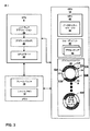
[0028] 図2は、3次元シーンの2次元表現を作るためにGPU12によって行われ得る例示的なグラフィックス処理パイプライン24を例示するブロック図である。グラフィックス処理パイプライン24は、グラフィックス処理コマンドを実行するために共に動作する複数のグラフィックス処理ステージを含み得る。図2に示されるように、グラフィックス処理パイプライン24は、入力アセンブラ26、頂点シェーダステージ(vertex shader stage)28、ハルシェーダステージ(hull shader stage)30、テッセレータステージ(tessellator stage)32、ドメインシェーダステージ34、ジオメトリシェーダステージ36、およびピクセルシェーダステージ38を含み得る。グラフィックス処理パイプライン24の中のコンポーネントの各々は、固定機能コンポーネント(fixed-function components)、(例えば、プログラマブルシェーダユニット上で実行しているシェーダプログラムの一部としての)プログラマブルコンポーネントとして、または固定機能とプログラマブルコンポーネントの組み合わせとしてインプリメントされ得る。
[0028] FIG. 2 is a block diagram illustrating an exemplary
[0029] GPU12は、GPUドライバ22を介して、CPU6から1つ以上のグラフィックス処理コマンドを受信するように、およびディスプレイ可能なグラフィックス画像(displayable graphics images)を生成するためにグラフィックス処理パイプライン24を介してグラフィックス処理コマンドを実行するように構成され得る。上記に説明されたように、グラフィックス処理パイプライン24は、グラフィックス処理コマンドを実行するために共に動作する複数のステージを含む。
[0029] The
[0030] グラフィックス処理パイプライン24の中の入力アセンブラ26は、グラフィックス処理パイプライン24にグラフィックスデータ(例えば、三角形、線、および点)を供給することを一般に担う固定機能ステージであり得る。例えば、入力アセンブラステージ26は、高次サーフェス(high order surfaces)、プリミティブ等のための頂点データを集めることができ、頂点データおよび属性を頂点シェーダステージ28に出力し得る。よって、入力アセンブラステージ26は、固定機能オペレーションを使用して、システムメモリ10のような、オフチップメモリから頂点を読み取り得る。入力アセンブラステージ26は次に、これらの頂点からパイプライン作業項目(pipeline work items)を作ることができ、その一方で頂点識別子(「VertexIDs」)、インスタンス識別子(頂点シェーダに利用可能である(made available to)「InstanceIDs」)、およびプリミティブ識別子(ジオメトリシェーダおよびピクセルシェーダに利用可能である「PrimitiveIDs」)も生成する。入力アセンブラステージ26は、頂点を読み取ると、VertexIDs、InstanceIDs、およびPrimitiveIDsを自動的に生成し得る。
[0030] The input assembler 26 in the
[0031] 頂点シェーダステージ28は、受信された頂点データおよび属性を処理し得る。例えば、頂点シェーダステージ28は、変換(transformations)、スキニング(skinning)、頂点変位(vertex displacement)、および頂点ごとの物質属性(per-vertex material attributes)を計算することのような頂点ごとの処理を行い得る。いくつかの例では、頂点シェーダステージ28は、テクスチャ座標、頂点カラー(vertex color)、頂点ライティング(vertex lighting)、フォグファクタ(fog factors)等を生成し得る。頂点シェーダステージ28は一般に、単一の入力頂点を取り、単一の、処理された出力頂点を出力する。
[0031]
[0032] ハルシェーダステージ30、テッセレータ32、およびドメインシェーダステージ34は、テッセレーションステージと集合的に称され得る。テッセレーションステージは、低詳細サブディビジョンサーフェス(low-detail subdivision surfaces)を高詳細プリミティブ(higher-detail primitives)に変換し(convert)、レンダリングのために高次サーフェスを適したサーフェス(例えば、三角形)にタイル表示する(tiles)。ハルシェーダステージ30は、頂点シェーダステージ28からプリミティブを受信し、少なくとも2つのアクションを実行することを担う。まず、ハルシェーダステージ30は、テッセレーションファクタのセットを決定することを典型的に担う。ハルシェーダステージ30は、プリミティブごとに1回テッセレーションファクタを生成し得る。テッセレーションファクタは、所与のプリミティブをどのくらい細かく(how finely)テッセレートする(tessellate)(例えば、プリミティブをより小さいパーツに分割する)かを決定するためにテッセレータステージ32によって使用され得る。ハルシェーダステージ30はまた、ドメインシェーダステージ34によって後で使用されることとなる制御点(control points)を生成することも担う。すなわち、例えば、ハルシェーダステージ30は、実際にテッセレートされた頂点(actual tessellated vertices)を作るためにドメインシェーダステージ34によって使用されることとなる制御点を生成することを担い、それは、レンダリングで最終的に使用される。
[0032] The
[0033] テッセレータステージ32がハルシェーダステージ30からデータを受信するとき、テッセレータステージ32は、現在のプリミティブタイプのための適切なサンプリングパターンを決定するためにいくつかのアルゴリズムのうちの1つを使用する。例えば、一般に、テッセレータステージ32は、(ハルシェーダステージ30によって決定されるような)テッセレーションの要求された量を現在の「ドメイン」内の座標点のグループに変換する。すなわち、ハルシェーダステージ30からのテッセレーションファクタ、ならびにテッセレータステージ32の特定の構成に依存して、テッセレータステージ32は、現在のプリミティブの中のどの点が入力プリミティブをより小さいパーツにテッセレートするためにサンプリングされる必要があるかを決定する。テッセレータステージ32の出力は、ドメイン点のセットであることができ、それは、重心座標(barycentric coordinates)を含み得る。
[0033] When
[0034] ドメインシェーダステージ34は、ハルシェーダステージ30によって作り出される制御点に加えて、ドメイン点を取り、新たな頂点を作るためにドメイン点を使用する。ドメインシェーダステージ34は、各テッセレートされた点に関する重心「ロケーション(location)」をパイプラインの中の次のステージにパスされる出力ジオメトリに変換するための現在のプリミティブ、テクスチャ、手続型のアルゴリズム(procedural algorithms)、またはその他のもののために生成される制御点の完全なリスト(complete list)を使用することができる。
[0034] In addition to the control points created by the
[0035] ジオメトリシェーダステージ36は、その頂点データ(例えば、三角形のための3つの頂点、線のための2つの頂点、または点のための単一の頂点)によって定義されるプリミティブを受信することができ、プリミティブをさらに処理し得る。例えば、ジオメトリシェーダステージ36は、他の可能性がある処理オペレーションの間で、シルエットエッジ検出(silhouette-edge detection)およびシャドウボリューム押出し(shadow volume extrusion)のようなプリミティブごとの処理を行い得る。よって、ジオメトリシェーダステージ36は、(1つ以上の頂点を含み得る)入力および出力0、1、または(この場合も先と同様に(again)1つ以上の頂点を含み得る)複数のプリミティブとして1つのプリミティブを受信し得る。出力プリミティブは、ジオメトリシェーダステージ36なしで可能であり得るより多くのデータを包含し得る。出力データの総量は、頂点カウントを乗じた(multipled by the vertex count)頂点サイズと同等であることができ、起動(invocation)ごとに制限され得る。ジオメトリシェーダステージ36からのストリーム出力は、このステージに達するプリミティブが、システムメモリ10のようなオフチップメモリに記憶されることを可能にし得る。ストリーム出力は、ジオメトリシェーダステージ36に典型的に関係しており(tied)、両方は、(例えば、APIを使用して)共にプログラムされ得る。
[0035] The
[0036] ラスタライザステージ(rasterizer stage)37は典型的に、ピクセルシェーダステージ38のために、プリミティブをクリッピングすること、およびプリミティブを準備することを担う固定機能ステージである。例えば、ラスタライザステージ37は、(カスタムクリップ境界(custom clip boundaries)を含む)クリッピング、パースペクティブデバイド(perspective divide)、ビューポート/切り取り選択(viewport/scissor selection)、およびインプリメンテーションを行うことができ、ターゲット選択およびプリミティブセットアップをレンダリングし得る。このようにして、ラスタライザステージ37は、ピクセルシェーダステージ38によってシェーディングするためのいくつかのフラグメント(fragments)を生成し得る。
[0036] The
[0037] ピクセルシェーダステージ38は、ラスタライザステージ37からフラグメントを受信し、カラーのような、ピクセルごとのデータを生成する。ピクセルシェーダステージ38はまた、テクスチャブレンディング(texture blending)およびライティングモデル計算(lighting model computation)のようなピクセルごとの処理も行い得る。よって、ピクセルシェーダステージ38は、入力として1つのピクセルを受信することができ、同じ相対位置(relative position)(またはピクセルのためのゼロ値)で1つのピクセルを出力し得る。
[0037] The
[0038] 本開示の態様にしたがって、グラフィックス処理パイプライン24の2つ以上のステージは、グラフィックスメモリ40の中で共有されるデータチャネルを共有し得る。例えば、頂点シェーダステージ28およびドメインシェーダステージ34によって作り出される頂点は、共有されるデータチャネルの中に記憶され得る。さらに、ハルシェーダステージ30およびジオメトリシェーダステージ36によって作り出されるプリミティブは、別の共有されるデータチャネルの中に記憶され得る。このようにして、GPU12は、グラフィックスメモリ40をより効率的に利用し得る。
[0038] In accordance with aspects of the present disclosure, two or more stages of
[0039] 図3は、さらに詳細に図1のCPU6、GPU12、およびシステムメモリ10の例示的なインプリメンテーションを例示するブロック図である。図3に示されるように、CPU6は、少なくとも1つのソフトウェアアプリケーション18、グラフィックスAPI20、およびGPUドライバ22を含むことができ、それらの各々は、CPU6上で実行する1つ以上のソフトウェアアプリケーションまたはサービスであり得る。
[0039] FIG. 3 is a block diagram illustrating an exemplary implementation of CPU 6,
[0040] CPU6およびGPU12に利用可能であるメモリは、システムメモリ10およびフレームバッファ16を含み得る。フレームバッファ16は、システムメモリ10の一部であることができ、またはシステムメモリ10から分離され得る。フレームバッファ16は、レンダリングされた画像データを記憶し得る。
[0040] Memory available to the CPU 6 and
[0041] ソフトウェアアプリケーション18は、GPU12の機能を利用する任意のアプリケーションであり得る。例えば、ソフトウェアアプリケーション18は、GUIアプリケーション、オペレーティングシステム、ポータブルマッピングアプリケーション(portable mapping application)、エンジニアリングまたは芸術的なアプリケーション(artistic applications)のためのコンピュータ支援設計プログラム(computer-aided design program)、ビデオゲームアプリケーション、あるいは2Dまたは3Dグラフィックスを使用する別のタイプのソフトウェアアプリケーションであり得る。
[0041] The software application 18 may be any application that uses the function of the
[0042] ソフトウェアアプリケーション18は、グラフィカルユーザインタフェース(GUI)および/またはグラフィックスシーンをレンダリングするためにGPU12に命令する1つ以上の描画命令を含み得る。例えば、描画命令は、GPU12によってレンダリングされるための1つ以上のグラフィックスプリミティブのセットを定義する命令を含み得る。いくつかの例では、描画命令は、GUIで使用される複数のウィンドウイングサーフェス(windowing surfaces)のすべてまたは一部を集合的に定義し得る。追加の例では、描画命令は、アプリケーションによって定義されるモデルスペースまたはワールドスペース内の1つ以上のグラフィックスオブジェクトを含むグラフィックスシーンのすべてまたは一部を集合的に定義し得る。
[0042] The software application 18 may include a graphical user interface (GUI) and / or one or more drawing instructions that instruct the
[0043] ソフトウェアアプリケーション18は、1つ以上のグラフィックスプリミティブをディスプレイ可能なグラフィックス画像にレンダリングするためのGPU12への1つ以上のコマンドを発行するために、グラフィックスAPI20を介して、GPUドライバ22を呼び出し得る。例えば、ソフトウェアアプリケーション18は、GPU12にプリミティブ定義(primitive definitions)を提供するために、グラフィックスAPI20を介して、GPUドライバ22を呼び出し得る。いくつかの例では、プリミティブ定義は、例えば、三角形、長方形、トライアングルファン(triangle fans)、トライアングルストリップ(triangle strips)等の描画プリミティブのリストの形でGPU12に提供され得る。プリミティブ定義は、レンダリングされるためのプリミティブと関連する1つ以上の頂点を特定する頂点仕様(vertex specifications)を含み得る。頂点仕様は、各頂点に関する位置座標(positional coordinates)および、いくつかの例では、例えば、カラー座標、法線ベクトル(normal vectors)、およびテクスチャ座標のような、頂点と関連する他の属性を含み得る。プリミティブ定義はまた、プリミティブタイプの情報(例えば、三角形、長方形、トライアングルファン、トライアングルストリップ等)、スケーリング情報、回転情報等も含み得る。ソフトウェアアプリケーション18によってGPUドライバ22に発行される命令に基づいて、GPUドライバ22は、プリミティブをレンダリングするために行うためのGPU12のための1つ以上のオペレーションを特定する1つ以上のコマンドを公式化し(formulate)得る。GPU12がCPU6からコマンドを受信するとき、グラフィックス処理パイプライン24は、そのコマンドを復号し、そのコマンドにおいて特定されたオペレーションを行うようにグラフィックス処理パイプライン24を構成する。例えば、グラフィックス処理パイプライン24の中の入力アセンブラ26は、プリミティブデータを読み取ることができ、グラフィックス処理パイプライン24の中の他のグラフィックスパイプラインステージによる使用のためにデータをプリミティブにアセンブルし(assemble)得る。特定されたオペレーションを行った後、グラフィックス処理パイプライン24は、ディスプレイデバイスと関連するフレームバッファ16にレンダリングされたデータを出力する。
[0043] The software application 18 uses a GPU driver via the graphics API 20 to issue one or more commands to the
[0044] フレームバッファ16は、GPU12のために宛先ピクセル(destination pixels)を記憶する。各宛先ピクセルは、一意的なスクリーンピクセルロケーションと関連し得る。いくつかの例では、フレームバッファ16は、各宛先ピクセルのための宛先アルファ値(destination alpha value)およびカラーコンポーネントを記憶し得る。例えば、フレームバッファ16は、「RGB」コンポーネントがカラー値に対応し、「A」コンポーネントが宛先アルファ値に対応する各ピクセルに関する赤、緑、青、アルファ(RGBA)コンポーネントを記憶し得る。フレームバッファ16およびシステムメモリ10は、別個のメモリユニットであるように例示されているが、他の例では、フレームバッファ16は、システムメモリ10の一部であり得る。
[0044] The frame buffer 16 stores destination pixels for the
[0045] いくつかの例では、グラフィックス処理パイプライン24の頂点シェーダステージ28、ハルシェーダステージ30、ドメインシェーダステージ34、ジオメトリシェーダステージ、およびピクセルシェーダステージ38は、シェーダステージと見なされ得る。これらのシェーダステージは、GPU12の中のシェーダユニット46上で実行する1つ以上のシェーダプログラムとしてインプリメントされ得る。シェーダユニット46は、処理コンポーネントのプログラマブルパイプラインとして構成され得る。いくつかの例では、シェーディングユニット(shading unit)46は、「シェーダプロセッサ」、または「統合シェーダ(unified shaders)」と称されることができ、グラフィックスをレンダリングするためにジオメトリ、頂点、ピクセル、または他のシェーディングオペレーションを行い得る。シェーダユニット46は、プロセッサコア48を含むことができ、それらの各々は、オペレーションをフェッチする(fetching)および復号するための1つ以上のコンポーネント、算術計算(arithmetic calculations)を実行するための1つ以上の算術論理ユニット(arithmetic logic units)、1つ以上のメモリ、キャッシュ、およびレジスタを含み得る。
[0045] In some examples,
[0046] GPU12は、グラフィックス処理パイプライン24の中の頂点シェーダステージ28、ハルシェーダステージ30、ドメインシェーダステージ34、ジオメトリシェーダステージ36、およびピクセルシェーダステージ38のうちの1つ以上を実行するためにコマンドをシェーダユニット46に送ることによって、頂点シェーディング、ハルシェーディング、ドメインシェーディング、ジオメトリシェーディング、ピクセルシェーディング等のような様々なシェーディングオペレーションを行うためにシェーダユニット46を指定し得る。いくつかの例では、GPUドライバ22は、1つ以上のシェーダプログラムをコンパイルするように、およびコンパイルされたシェーダプログラムをGPU12内に包含される1つ以上のプログラマブルシェーダユニットにダウンロードするように構成され得る。シェーダプログラムは、例えば、OpenGLシェーディング言語(GLSL)、ハイレベルシェーディング言語(HLSL)、グラフィックスのためのC(Cg)シェーディング言語(C for Graphics (Cg) shading language)等のような、ハイレベルシェーディング言語で書き込まれ得る。コンパイルされたシェーダプログラムは、GPU12内のシェーダユニット46のオペレーションを制御する1つ以上の命令を含み得る。例えば、シェーダプログラムは、頂点シェーダステージ28の機能を行うためにシェーダユニット46によって実行され得る頂点シェーダプログラム、ハルシェーダステージ30の機能を行うためにシェーダユニット46によって実行され得るハルシェーダプログラム、ドメインシェーダステージ34の機能を行うためにシェーダユニット46によって実行され得るドメインシェーダプログラム、ジオメトリシェーダステージ36の機能を行うためにシェーダユニット46によって実行され得るジオメトリシェーダプログラム、および/またはピクセルシェーダ38の機能を行うためにシェーダユニット46によって実行され得るピクセルシェーダプログラムを含み得る。頂点シェーダプログラムは、プログラマブル頂点シェーダユニット、または統合(unified)シェーダユニットの実行を制御することができ、1つ以上の頂点ごとのオペレーションを特定する命令を含み得る。
[0046]
[0047] グラフィックスメモリ40は、GPU12の集積回路に物理的に組み込まれるオンチップ記憶装置、またはメモリである。グラフィックスメモリ40がオンチップであるため、GPU12は、システムバスを介してシステムメモリ10から値を読み取ること、またはシステムメモリ10に値を書き込むことより速くグラフィックスメモリ40から値を読み取り、またはグラフィックスメモリ40に値を書き込むことができ得る。そのようなものとして、シェーダユニット46のパフォーマンスは、グラフィックスメモリ40からグラフィックス処理パイプライン24のシェーダステージによって作り出される、および消費されるデータを読み取ること、および記憶することによって増加され得る。
The
[0048] 本開示の態様にしたがって、シェーダユニット46は、プロセッサコア48上で同時に複数のシェーディングオペレーションを行い得る。GPU12は、異なるプロセッサコア48上で実行されるためのグラフィックス処理パイプライン24の異なるシェーディングステージをイネーブルする(enable)コマンドをシェーディングユニット46に送ることができ、それによってグラフィックス処理パイプライン24のステージをインタリーブする。例えば、GPU12は、シェーディングユニット46に、シェーダユニット46の異なるプロセッサコア48上で同時に頂点シェーダステージ28およびジオメトリシェーダステージ36を実行させるコマンドをシェーディングユニット46に送り得る。別の例では、GPU12は、シェーディングユニット46に、複数のプロセッサ上で同時にジオメトリシェーダステージ36の複数の例を実行させるコマンドをシェーディングユニット46に送り得る。
[0048] In accordance with aspects of this disclosure, shader unit 46 may perform multiple shading operations on processor core 48 simultaneously. The
[0049] 本開示の態様にしたがって、グラフィックスメモリ40は、単一のデータチャネルを共有するためにグラフィックス処理パイプライン24の異なるステージによって作り出されるデータをイネーブルする(enable)共有されるデータチャネル50A−50N(「共有されるデータチャネル50」)のうちの1つ以上を含むことができ、それによってGPU12がグラフィックスメモリ40の中の限られたスペースをより効率的に利用することをイネーブルし、またシェーダプロセッサクラスタ46がグラフィックス処理パイプライン24の複数のステージを同時に実行するためにそのプロセッサコア48の利用を増加させることもイネーブルする。
[0049] In accordance with aspects of the present disclosure,
[0050] 共有されるデータチャネル50の中の各共有されるデータチャネルは、グラフィックス処理パイプライン24の2つ以上のステージによって作り出されるデータを記憶し得る。グラフィックス処理パイプライン24の個別のステージのためにデータチャネルを割り当てることとは対照的に、共有されるデータチャネル50の中の共有されるデータチャネルを共有することによって、グラフィックス処理パイプライン24の中のステージがより少ないデータを作り出す場合、同じ共有されるデータチャネルを共有する別のステージは、それが共有されるデータチャネルの中で作り出すより多くのデータを記憶することによってそのファクト(fact)を活用することが可能であり得る。
[0050] Each shared data channel in shared data channel 50 may store data produced by two or more stages of
[0051] 本開示の態様にしたがって、ジオメトリ処理ユニット(GPC)42は、共有されるデータチャネル50のステータスに基づいてシェーダプロセッサクラスタ46の実行をスケジューリングし得る。GPC42は、シェーダプロセッサクラスタ46によって実行されるためにグラフィックス処理パイプライン24のステージによって消費されるための十分なデータが共有されるデータチャネル50の中にあるか否かを決定するために、共有されるデータチャネル50をモニタし(monitor)得る。GPC42はまた、シェーダプロセッサクラスタ46によって実行されるためにグラフィックス処理パイプライン24のステージによって作り出されるデータを記憶するための十分なフリースペースが共有されるデータチャネル50の中にあるか否かを決定するために、共有されるデータチャネル50をモニタし得る。GPC42が、共有されるデータチャネル50の中に十分なデータおよびフリースペースが存在することを決定する場合、GPC42は、グラフィックス処理パイプライン24のステージのバッチ(batch of stages)を実行するために、実行コマンドをシェーダプロセッサクラスタ46に送り得る。ステージのバッチの実行を完了したことに応答して、シェーダプロセッサクラスタ46は、プロセッサクラスタ46がステージのバッチの実行を完了したことを示す信号をGPC42に送り得る。それに応答して、データチャネルマネージャ(data channel manager)44は、共有されるデータチャネル50のための関連のある読み取りおよび書き込みポインタをアップデートし得る。GPC42は、共有されるデータチャネル50を管理するデータチャネルマネージャ44を含み得る。データチャネルマネージャ44は、共有されるデータチャネル50にデータを書き込む、および共有されるデータチャネル50からデータを読み取るために共有されるデータチャネル50内でロケーションを指し示す共有されるデータチャネル50のための読み取りおよび書き込みポインタを管理し得る。
In accordance with aspects of this disclosure, geometry processing unit (GPC) 42 may schedule execution of shader processor cluster 46 based on the status of shared data channel 50. The
[0052] 本開示の態様にしたがって、共有されるデータチャネル50Aは、共有されるデータチャネル50Aがグラフィックス処理パイプライン24の第1のステージによって出力されたデータ55Aと、グラフィックス処理パイプライン24の第2のステージによって出力されたデータ55Bの両方を記憶し得るように、グラフィックス処理パイプライン24の2つ以上のステージによって共有されるデータチャネルであり得る。共有されるデータチャネル50Aは、データ55Aおよび55Bが、それらが作り出された、および/または消費されたとき、そのサイズを動的に増加と低減の両方をさせることができるようにリングバッファであることができ、それによって共有されるデータチャネル50Aに割り当てられたメモリブロックのより効率的な使用を可能にする。GPC42は、書き込みポインタ51Aおよび51B、ならびに読み取りポインタ53Aおよび53Bを管理し得る。書き込みポインタ51Aは、データ55Aを書き込むために、共有されるデータチャネル50Aのメモリロケーションを指し示すことができ、読み取りポインタ53Aは、データ55Aを読み取るために、共有されるデータチャネル50Aのメモリロケーションを指し示し得る。
[0052] In accordance with aspects of this disclosure, the shared
[0053] 典型的に、読み取りポインタ53Aおよび53Bが、それぞれ、キューの先頭(head of the queue)と称されることもある、データ55Aおよび55Bの中のデータの最も古い部分(oldest piece)を記憶する共有されるデータチャネル50Aのメモリロケーションを指し示すように、ならびに書き込みポインタ51Aおよび51Bが、それぞれ、キューの末端(tail of the queue)と称されることもある、データ55Aおよび55Bの中のデータの最も新しい部分を記憶する共有されるデータチャネル50Aのメモリロケーションを指し示すように、GPU12は、ファーストインファーストアウト(first-in-first-out)(FIFO)の順序で共有されるデータチャネル50Aの中にデータ55Aおよび55Bを記憶する。
[0053] Typically, read
[0054] 共有されるデータチャネル50Aはまた、データ55Aおよび55Bから読み取られたデータが共有されるデータチャネル50Aから削除され、それらのメモリロケーションが割り当てを解除され(deallocated)得るようにFIFOモードで動作し得る。以上のように、GPU12が共有されるデータチャネル50Aからデータ55Aを読み取るとき、共有されるデータチャネル50Aの中のフリースペース57は増加し、それによってGPU12のための共有されるデータチャネル50Aの中の追加のスペースがデータ55Bにデータを書き込むことを可能にする。同様に、GPU12が共有されるデータチャネル50Aからデータ55Bを読み取るとき、共有されるデータチャネル50Aの中のフリースペース59は増加し、それによってGPU12のための共有されるデータチャネル50Aの中の追加のスペースがデータ55Aにデータを書き込むことを可能にする。共有されるデータチャネル50Aのみが上記に詳細に説明されたが、共有されるデータチャネル50の中の各共有されるデータチャネルが、共有されるデータチャネル50Aに関して上記に説明された特徴を共有し得ることは理解されるべきである。
[0054] Shared data channel 50A is also in FIFO mode so that data read from
[0055] 図4は、グラフィックス処理パイプライン24の中で使用されている共有されるデータチャネル50の例を例示するブロック図である。図4に示されるように、共有されるデータチャネル50Aは、ステージによって作り出されるデータを記憶するためにグラフィックス処理パイプライン24のステージによって共有され得る。
具体的には、共有されるデータチャネル50Aは、グラフィックス処理パイプライン24のハルシェーダステージ30によって作り出されるデータ52を記憶することができ、グラフィックス処理パイプライン24のジオメトリシェーダステージ36によって作り出されるデータ54をさらに記憶し得る。データ52は、グラフィックス処理パイプライン24のドメインシェーダステージ34によって消費されることができ、データ54は、グラフィックス処理パイプライン24のピクセルシェーダステージによって消費され得る。
FIG. 4 is a block diagram illustrating an example of a shared data channel 50 that is used in the
Specifically, the shared
[0056] ハルシェーダステージ30およびジオメトリシェーダステージ36によって共有されるデータチャネル50Aに記憶されたデータ52およびデータ54は、それぞれ、ハルシェーダステージ30によって出力されるパッチ制御点およびジオメトリシェーダステージ36によって出力される頂点を含み得る。データチャネル50Aがデータ52および54をキャッシュしないため、データ52および54は、データ52および54から読み取られるデータが共有されるデータチャネル50Aから削除されるFIFOキューとして各々動作し得る。
[0056]
[0057] いくつかの例では、グラフィックス処理パイプライン24のいくつかのステージによって作り出される同じデータは、グラフィックス処理パイプライン24の他のステージによって複数回(multiple times)消費され得る。データがFIFOキューとして動作する共有されるデータチャネル50の1つに記憶される場合、FIFOキューに記憶されるデータがそれがFIFOキューから読み取られるとき削除され得るため、データを作り出すグラフィックス処理パイプライン24のステージは、同じデータを作り出すために複数回実行する必要があり得る。複数回同じ頂点を作り出すために複数回頂点シェーダ28またはドメインシェーダ34を実行することに代わって、GPU12は、キャッシュモード共有チャネル56の中で頂点シェーダ28およびドメインシェーダ34によって作り出されるデータを代わりにキャッシュし得る。
[0057] In some examples, the same data created by several stages of the
[0058] 例えば、頂点シェーダステージ28によって変換される頂点を含む、グラフィックス処理パイプライン24の頂点シェーダステージ28によって作り出されるデータは、グラフィックス処理パイプライン24のハルシェーダステージ30によって消費され得る。同様に、ドメインシェーダステージ34によって出力される頂点位置のような、グラフィックス処理パイプライン24のドメインシェーダステージ34によって作り出されるデータは、グラフィックス処理パイプライン24のジオメトリシェーダステージ36によって消費され得る。例えば、近接したプリミティブ(例えば、三角形)が頂点を共有し得るため、同じ頂点は、2つの近接した三角形を形成するために使用され得る。したがって、頂点シェーダステージ28およびドメインシェーダステージ34によって作り出される頂点データは、複数回消費され得る。頂点シェーダステージ28およびドメインシェーダステージ34によって作り出されるデータは、複数回消費され得るため、これらのステージによって作り出されるデータは、キャッシュされたデータが、それがキャッシュモード共有チャネル56から読み取られることに応答して削除され得ないように、キャッシュモード共有チャネル56の中でキャッシュされ得る。
[0058] For example, data produced by
[0059] 図5は、キャッシュモード共有チャネル56を例示するブロック図である。図5に示されるように、キャッシュモード共有チャネル56は、2つの共有されるデータチャネル:共有されるプリミティブキュー50Bおよび共有される頂点キャッシュ50C、ならびにキャッシュウィンドウ70を含み得る。共有される頂点キャッシュ50Cは、共有される頂点キャッシュ50Cに記憶されるデータが共有される頂点キャッシュ50Cから読み取られる際に削除されない場合があるようにキャッシュモードで動作し得る。共有されるプリミティブキュー50Bに記憶されるデータ62およびデータ64は、頂点シェーダステージ28およびドメインシェーダステージ34によって作り出されるプリミティブデータを含み得る。例えば、データ62は、各プリミティブのために頂点シェーダステージ28によって作り出された、共有される頂点キャッシュ50Cで記憶された頂点データの頂点インデックスおよびロケーションを含むことができ、データ64は、各プリミティブのためにドメインシェーダステージ34によって作り出された、共有される頂点キャッシュ50Cで記憶された頂点データの頂点インデックスおよびロケーションを含み得る。データ62および64はまた、関連するプリミティブの各々のための割り当て解除フラグ(deallocation flags)を含み得る。共有される頂点キャッシュ50Cに記憶されたデータ66は、頂点シェーダステージ28によって変換された頂点を含むことができ、一方、共有される頂点キャッシュ50Cに記憶されたデータ68は、ドメインシェーダステージ34によって出力された頂点位置を含み得る。GPC42は、キャッシュモード共有チャネル56がデータを受け取るために十分なフリースペースを有するか否かを決定するために、共有されるプリミティブキュー50Bと共有される頂点キャッシュ50Cの両方のフリースペースをチェックし得る。
FIG. 5 is a block diagram illustrating the cache mode shared
[0060] キャッシュウィンドウ70は、特定の頂点が、共有される頂点キャッシュ50Cの限られたウィンドウの中に既に記憶されている場合、インジケーションを記憶し得る。例えば、キャッシュウィンドウ70は、フリーアソシアティブキャッシュ(fully associative cache)として動作することができ、頂点を消費し得るシェーダの、共有される頂点キャッシュ50C内の頂点のデータロケーション、頂点インデックス、およびフラグのような、インジケーションを記憶し得る。 [0060] The cache window 70 may store an indication if a particular vertex is already stored in a limited window of the shared vertex cache 50C. For example, the cache window 70 can operate as a fully associative cache, such as vertex data locations, vertex indices, and flags of shared vertex cache 50C for shaders that can consume vertices. Indications can be stored.
[0061] プリミティブによるGPC42処理ジオメトリプリミティブ。頂点シェーダ28およびドメインシェーダ34のために、GPC42が、頂点インデックス上のキャッシュウィンドウ70、および/または頂点が属するシェーダをチェックすることに基づいて、プリミティブの特定の頂点が共有される頂点キャッシュ50Cの中に存在しないことを決定する場合、キャッシュミスが発生することがあり得、そしてGPC42は、所望の頂点を作り出すために、およびキャッシュモード共有チャネル56の中に作り出された頂点データを記憶するために適切なシェーダステージ(例えば、頂点シェーダ28またはドメインシェーダ34)を実行するためのコマンドをシェーダユニット46に送り得る。GPC42は、共有される頂点キャッシュ50Cで頂点データの頂点インデックスおよびロケーションを共有されるプリミティブキュー50Bに追加し得る。GPC42は、キャッシュモード共有チャネル56の中の今キャッシュされた頂点に関する適切なデータをキャッシュウィンドウ70に追加し得る。キャッシュウィンドウ70は、キャッシュミスの後にキャッシュウィンドウ70の中に余地がない場合、キャッシュウィンドウ70の中の最も古いスロットの中に関連し、共有されるプリミティブキュー50Bの中にセットされたそれの割り当て解除フラグを有する頂点が、キャッシュモード共有チャネル56に追加される最新の頂点に関する情報でセットされ得るようにファーストインファーストアウト(FIFO)の方法で動作し得る。しかしながら、GPC42が特定の頂点がキャッシュモード共有チャネル56の中でキャッシュされることを決定する場合、GPC42は、所望の頂点の共有される頂点キャッシュ50Cの中のメモリロケーションを使用することができ、共有される頂点キャッシュ50Cで頂点データの頂点インデックスおよびロケーションを共有されるプリミティブキュー50Bに追加することができる。このようにして、GPU12は、グラフィックス処理パイプライン24の中のステージの無関係な処理(extraneous processing)を低減することができる。
[0061] GPC42 processing geometry primitive by primitive. For the
[0062] ハルシェーダ30およびジオメトリシェーダ36を実行するために、GPC42は、共有されるプリミティブキュー50Bと共有される頂点キャッシュ50Cの両方からデータを消費し得る。GPC42は、共有されるプリミティブキュー50Bから共有される頂点キャッシュ50Cの中の頂点データの頂点インデックスおよびロケーションを読み取り得る。GPC42は次に、共有されるプリミティブキュー50Bから読み取ったロケーションを使用して、共有される頂点キャッシュ50Cから頂点データを読み取り得る。GPC42は、データを読み取った後、共有されるプリミティブキュー50Bの読み取りポインタを動かし得る。しかしながら、続くプリミティブが、共有される頂点キャッシュ50Cから丁度読み取られた同じ頂点も使用し得るため、キャッシュされた頂点が、共有される頂点キャッシュ50Cから読み取られた直後、GPC42は、共有される頂点キャッシュ50Cの読み取りポインタを即時に動かさないことがある。頂点を消費するプリミティブのための共有されるプリミティブキュー50Bの中の関連する割り当てを解除されたフラグがセットされる場合、GPC42は、読み取りポインタを動かすこと、およびキャッシュモード共有チャネル56から頂点を割り当て解除することを可能にされ得る。GPC42は、頂点データを消費するためのシェーダステージ(例えば、ハルシェーダ30およびジオメトリシェーダ36)を実行するために、および次のシェーダステージのための頂点を作り出し、共有されるデータチャネル50Aの中の作り出された頂点データを記憶するためにコマンドをシェーダユニット46に送り得る。
[0062] To execute the
[0063] GPC42は、デッドロックのためのキャッシュモード共有チャネル56および共有されるデータチャネル50Aをモニタし得る。一例では、キャッシュモード共有チャネル56が頂点シェーダステージ28によって作り出されるデータでいっぱいである場合、および共有されるデータチャネル50Aがハルシェーダステージ30によって作り出されるデータでいっぱいである場合、デッドロックは、発生し得る。この場合では、ハルシェーダステージ30が頂点ステージ28によって作り出されたデータを消費するため、ハルシェーダステージ30は、新たに作り出されたデータを記憶するための共有されるデータチャネル50Aの中のフリースペースが存在しないため、共有されるデータチャネル50Aに記憶されたデータを作り出すために頂点シェーダステージ28によって作り出され、キャッシュモード共有チャネル56の中に記憶されるデータを消費することができない。さらに、キャッシュモード共有チャネル56が、頂点シェーダステージ28によって作り出されるデータでいっぱいであり、そのデータのいずれもハルシェーダ30によって消費されることができないため、そのデータのいずれも、ドメインシェーダ34によって作り出されたデータを記憶するためのキャッシュモード共有チャネル56に関するスペースを解放する(free up)ために割り当てを解除されることができない。さらに、ドメインシェーダ34がハルシェーダステージ30によって作り出され、共有されるデータチャネル50Aの中に記憶されるデータを消費するため、ハルシェーダ30Aによって作り出され、共有されるデータチャネル50Aの中に記憶されるデータのいずれも、ジオメトリシェーダ36によって作り出されたデータを記憶するための共有されるデータチャネル50Aに関する、共有されるデータチャネル50Aの中のスペースを解放するためにドメインシェーダ34によって消費されることができない。
[0063]
[0064] キャッシュモード共有チャネル56と共有されるデータチャネル50A間のデッドロック状況を防ぐために、キャッシュモード共有チャネル56および共有されるデータチャネル50Aがそれぞれ、頂点シェーダ28およびハルシェーダ30によって作り出されるデータを記憶するだけでないように、GPC42は、それぞれドメインシェーダ34およびジオメトリシェーダ36によって作り出されるデータを記憶するためにキャッシュモード共有チャネル56および共有されるデータチャネル50Aの中のスペースを保持し(reserve)得る。GPC42は、共有されるプリミティブキュー50Bと共有される頂点キャッシュ50Cの両方のコンポーネントの中でキャッシュモード共有チャネル56のスペースの量、および例えば、シェーダクラスタ46の中の所与の数の波(waves)のためにドメインシェーダ34およびジオメトリシェーダ36からの出力を記憶するために必要であるスペースの量を決定することによって、保持するべき共有されるデータチャネル50Aのスペースの量を決定し得る。
[0064] In order to prevent a deadlock situation between the cache mode shared
[0065] 図6は、グラフィックス処理パイプラインのステージによってデータチャネルを共有するための例示的なプロセスを例示する流れ図である。図6に示されるように、処理は、GPU12が、グラフィックス処理パイプライン24の少なくとも2つのステージによって共有されるGPU12のオンチップグラフィックスメモリ40の中に共有されるデータチャネル50Aを割り当てることを含み得る(502)。プロセスは、GPU12の中のシェーダユニット46上で、グラフィックス処理パイプライン24の少なくとも2つのステージを実行することをさらに含み得る(504)。プロセスは、オンチップグラフィックスメモリ40の中の共有されるデータチャネル50Aの中にGPU12が、シェーダユニット46上で実行しているグラフィックス処理パイプライン24の少なくとも2つのステージによって作り出されるデータを記憶することをさらに含み得る(506)。
[0065] FIG. 6 is a flow diagram illustrating an exemplary process for sharing a data channel by stages of a graphics processing pipeline. As shown in FIG. 6, the process allows the
[0066] いくつかの例では、プロセスは、GPU12が、グラフィックス処理パイプライン24の第2の少なくとも2つのステージによって共有されるGPU12のオンチップグラフィックスメモリ40の中に第2のキャッシュモード共有チャネル56を割り当てることをさらに含むことができ、ここにおいて、共有されるデータチャネル50Aは、第1の共有されるデータチャネルである。いくつかの例では、プロセスは、GPU12の中のシェーダユニット46上で、グラフィックス処理パイプライン24の第2の少なくとも2つのステージを実行することをさらに含み得る。いくつかの例では、プロセスは、第2のキャッシュモード共有チャネル56の中にGPU12が、シェーダユニット46上で実行しているグラフィックス処理パイプライン24の第2の少なくとも2つのステージの各々によって作り出される第2のデータを記憶することをさらに含み得る。
[0066] In some examples, the process shares a second cache mode in the on-
[0067] いくつかの例では、データが、シェーダユニット46上で実行しているとき、グラフィックス処理パイプライン24の1つ以上のステージによって消費されるために第1の共有されるデータチャネル50A、または第2のキャッシュモード共有チャネル56で利用可能であり、ならびにフリースペースが、シェーダユニット46上で実行しているときグラフィックス処理パイプライン24の1つ以上のステージによって作り出されるデータを記憶するために第1の共有されるデータチャネル50A、または第2のキャッシュモード共有チャネル56で利用可能であるように、プロセスは、GPU12が、第1の共有されるデータチャネル50Aまたは第2のキャッシュモード共有チャネル56のステータスに少なくとも部分的に基づいてシェーダユニット46によってグラフィックス処理パイプライン24の1つ以上のステージの実行をスケジューリングすることをさらに含み得る。
[0067] In some examples, the first shared
[0068] いくつかの例では、グラフィックス処理パイプライン24の少なくとも2つのステージは、頂点シェーダ28およびドメインシェーダ34を含む。いくつかの例では、グラフィックス処理パイプライン24の第2の少なくとも2つのステージは、ハルシェーダ30およびジオメトリシェーダ36を含む。
[0068] In some examples, at least two stages of the
[0069] いくつかの例では、プロセスは、GPU12が、第1の共有されるデータチャネル50Aと第2のキャッシュモード共有チャネル56間のデッドロックを防ぐために、第1の共有されるデータチャネル50A、および第2のキャッシュモード共有チャネル56のうちの少なくとも1つの中のフリースペースを保持することをさらに含み得る。
[0069] In some examples, the process causes the first shared
[0070] 1つ以上の例では、説明された機能は、ハードウェア、ソフトウェア、ファームウェア、またはそれらの任意の組合せでインプリメントされ得る。ソフトウェアでインプリメントされる場合、これらの機能は、コンピュータ可読媒体上で、1つ以上の命令またはコードとして記憶または送信され得る。コンピュータ可読媒体は、1つの場所から別の場所へのコンピュータプログラムの転送を容易にするあらゆる媒体を含むコンピュータデータ記憶媒体または通信媒体を含み得る。データ記憶媒体は、本開示で説明された技法のインプリメンテーションのための命令、コード、および/またはデータ構造を取り出すために、1つ以上のコンピュータまたは1つ以上のプロセッサによってアクセスされることができるあらゆる利用可能な媒体であり得る。限定ではなく例として、そのようなコンピュータ可読媒体は、RAM、ROM、EEPROM、CD−ROMまたは他の光学ディスク記憶装置、磁気ディスク記憶装置または他の磁気記憶デバイス、あるいは命令またはデータ構造の形で所望のプログラムコードを搬送または記憶するために使用されることができ、コンピュータによってアクセスされることができる任意の他の媒体を備えることができる。また、任意の接続は、コンピュータ可読媒体と厳密には称される。例えば、ソフトウェアが、同軸ケーブル、光ファイバーケーブル、ツイストペア、デジタル加入者回線(DSL)、または赤外線、無線、およびマイクロ波のようなワイヤレス技術を使用して、ウェブサイト、サーバ、または他の遠隔ソースから送信される場合、同軸ケーブル、光ファイバーケーブル、ツイストペア、DSL、または赤外線、無線、およびマイクロ波のようなワイヤレス技術は、媒体の定義に含まれる。本明細書で使用される場合、ディスク(disk)およびディスク(disc)は、コンパクトディスク(CD)、レーザーディスク(登録商標)、光ディスク、デジタル多用途ディスク(DVD)、フロッピー(登録商標)ディスク、およびBlu−ray(登録商標)ディスクを含み、ここでディスク(disk)は通常、磁気的にデータを再生し、一方ディスク(disc)は、レーザーを用いて光学的にデータを再生する。上記の組み合わせはまた、コンピュータ可読媒体の範囲内に含まれるべきである。 [0070] In one or more examples, the functions described may be implemented in hardware, software, firmware, or any combination thereof. If implemented in software, the functions may be stored or transmitted as one or more instructions or code on a computer-readable medium. Computer-readable media can include computer data storage media or communication media including any medium that facilitates transfer of a computer program from one place to another. A data storage medium may be accessed by one or more computers or one or more processors to retrieve instructions, code, and / or data structures for implementation of the techniques described in this disclosure. It can be any available medium that can. By way of example, and not limitation, such computer readable media can be in the form of RAM, ROM, EEPROM, CD-ROM or other optical disk storage, magnetic disk storage or other magnetic storage device, or instructions or data structures. Any other medium that can be used to carry or store the desired program code and that can be accessed by a computer can be provided. Any connection is also strictly referred to as a computer-readable medium. For example, software can use a coaxial cable, fiber optic cable, twisted pair, digital subscriber line (DSL), or wireless technology such as infrared, wireless, and microwave from a website, server, or other remote source When transmitted, coaxial technologies, fiber optic cables, twisted pair, DSL, or wireless technologies such as infrared, radio, and microwave are included in the definition of media. As used herein, a disk and a disc are a compact disc (CD), a laser disc (registered trademark), an optical disc, a digital versatile disc (DVD), a floppy (registered trademark) disc, And Blu-ray® discs, where the disc typically reproduces data magnetically, while the disc reproduces data optically using a laser. Combinations of the above should also be included within the scope of computer-readable media.
[0071] コードは、1つ以上のデジタルシグナルプロセッサ(DSPs)、汎用マイクロプロセッサ、特定用途向け集積回路(ASICs)、フィールドプログラマブル論理アレイ(FPGAs)、または他の同等な集積またはディスクリート論理回路のような、1つ以上のプロセッサによって実行され得る。よって、本明細書で使用される場合、「プロセッサ」および「処理ユニット」という用語は、前述の構造、または本明細書に説明された技法のインプリメンテーションに適した任意の他の構造のいずれかを指し得る。加えて、いくつかの態様では、本明細書に説明された機能は、符号化および復号のために構成された専用ハードウェアおよび/またはソフトウェアモジュール内で提供され得る、あるいは組み合わせられたコーデックの中に組み込まれ得る。また、技法は、1つ以上の回路または論理要素で十分にインプリメントされることができる。 [0071] The code is like one or more digital signal processors (DSPs), general purpose microprocessors, application specific integrated circuits (ASICs), field programmable logic arrays (FPGAs), or other equivalent integrated or discrete logic circuits. Can be executed by one or more processors. Thus, as used herein, the terms “processor” and “processing unit” refer to either the aforementioned structure or any other structure suitable for implementation of the techniques described herein. Can point to. In addition, in some aspects, the functionality described herein may be provided in dedicated hardware and / or software modules configured for encoding and decoding, or in a combined codec. Can be incorporated into. Also, the techniques can be fully implemented with one or more circuits or logic elements.
[0072] 本開示の技法は、ワイヤレスハンドセット、集積回路(IC)またはICsのセット(すなわち、チップセット)を含む、幅広い様々なデバイスまたは装置においてインプリメントされ得る。様々なコンポーネント、モジュール、またはユニットは、開示された技法を行うように構成されるデバイスの機能的な態様を強調するために本開示の中で説明されるが、必ずしも異なるハードウェアユニットによる実現を要求しない。むしろ、上記に説明されたように、様々なユニットは、コーデックハードウェアユニットにおいて組み合わされ得るか、または適切なソフトウェアおよび/またはファームウェアと併せて、上記に説明されたような1つ以上のプロセッサを含む、相互運用のハードウェアユニット(interoperative hardware units)の集合によって提供され得る。 [0072] The techniques of this disclosure may be implemented in a wide variety of devices or apparatuses, including a wireless handset, an integrated circuit (IC) or a set of ICs (ie, a chipset). Various components, modules, or units are described in this disclosure to highlight functional aspects of a device configured to perform the disclosed techniques, but are not necessarily realized by different hardware units. Do not request. Rather, as described above, the various units can be combined in a codec hardware unit, or combined with appropriate software and / or firmware, with one or more processors as described above. It can be provided by a set of interoperating hardware units, including.
[0073] 様々な例が、説明された。これらおよび他の例は、以下の特許請求の範囲の範囲内にある。
以下に、本願出願の当初の特許請求の範囲に記載された発明を付記する。
[C1]
グラフィックス処理の方法であって、
グラフィックス処理ユニット(GPU)が、グラフィックス処理パイプラインの少なくとも2つのステージによって共有される前記GPUのオンチップグラフィックスメモリの中に共有されるデータチャネルを割り当てることと、
前記GPUの中のシェーダユニット上で、前記グラフィックス処理パイプラインの前記少なくとも2つのステージを実行することと、
オンチップグラフィックスメモリの中の前記共有されるデータチャネルの中に前記GPUが、前記シェーダユニット上で実行している前記グラフィックス処理パイプラインの前記少なくとも2つのステージの各々によって作り出されるデータを記憶することと、
を備える、方法。
[C2]
前記GPUが、前記グラフィックス処理パイプラインの第2の少なくとも2つのステージによって共有される前記GPUのオンチップグラフィックスメモリの中に第2の共有されるデータチャネルを割り当てることと、ここにおいて、前記共有されるデータチャネルは、第1の共有されるデータチャネルである、
前記GPUの中の前記シェーダユニット上で、前記グラフィックス処理パイプラインの前記第2の少なくとも2つのステージを実行することと、
前記第2の共有されるデータチャネルの中に前記GPUが、前記シェーダユニット上で実行している前記グラフィックス処理パイプラインの前記第2の少なくとも2つのステージの各々によって作り出される第2のデータを記憶することと、
をさらに備える、C1に記載の方法。
[C3]
データが、前記シェーダユニット上で実行している前記グラフィックス処理パイプラインの1つ以上のステージによって消費されるために前記第1の共有されるデータチャネル、または前記第2の共有されるデータチャネルにおいて利用可能であり、ならびにフリースペースが、前記シェーダユニット上で実行している前記グラフィックス処理パイプラインの前記1つ以上のステージによって作り出されるデータを記憶するために前記第1の共有されるデータチャネル、または前記第2の共有されるデータチャネルにおいて利用可能であるように、前記GPUが、前記第1の共有されるデータチャネル、または前記第2の共有されるデータチャネルのステータスに少なくとも部分的に基づいて前記シェーダユニット上で前記グラフィックス処理パイプラインの前記1つ以上のステージの前記実行をスケジューリングすることをさらに備える、C2に記載の方法。
[C4]
前記第1の共有されるデータチャネルは、前記第1の共有されるデータチャネルの中に記憶されたデータをキャッシュするためにキャッシュモードで動作し、前記第2の共有されるデータチャネルは、ファーストインファーストアウト(FIFO)モードで動作する、C2に記載の方法。
[C5]
前記第1の共有されるデータチャネルは、第1のリングバッファであり、前記第2の共有されるデータチャネルは、第2のリングバッファである、C2に記載の方法。
[C6]
前記第1の共有されるデータチャネルの中に記憶された前記データは、前記グラフィックス処理パイプラインの前記少なくとも2つのステージによって作り出される頂点データを備え、前記第2の共有されるデータチャネルの中に記憶された前記第2のデータは、前記グラフィックス処理パイプラインの前記第2の少なくとも2つのステージによって作り出されるプリミティブを備える、C2に記載の方法。
[C7]
前記グラフィックス処理パイプラインの前記少なくとも2つのステージは、頂点シェーダおよびドメインシェーダを備える、C6に記載の方法。
[C8]
前記グラフィックス処理パイプラインの前記第2の少なくとも2つのステージは、ハルシェーダおよびジオメトリシェーダを備える、C6に記載の方法。
[C9]
前記GPUが、前記第1の共有されるデータチャネルと前記第2の共有されるデータチャネル間のデッドロックを防ぐために、前記第1の共有されるデータチャネル、および前記第2の共有されるデータチャネルのうちの少なくとも1つの中のフリースペースを保持することをさらに備える、C2に記載の方法。
[C10]
グラフィックスデータを処理するように構成された装置であって、
グラフィックス処理パイプラインの少なくとも2つのステージによって共有されるグラフィックス処理ユニット(GPU)のオンチップグラフィックスメモリの中に共有されるデータチャネルを割り当てることと、
前記GPUの中のシェーダユニット上で、前記グラフィックス処理パイプラインの前記少なくとも2つのステージを実行することと、
オンチップグラフィックスメモリの中の前記共有されるデータチャネルの中に、前記シェーダユニット上で実行している前記グラフィックス処理パイプラインの前記少なくとも2つのステージの各々によって作り出されるデータを記憶することと、
を行うように構成される前記GPUを備える、装置。
[C11]
前記GPUは、
前記グラフィックス処理パイプラインの第2の少なくとも2つのステージによって共有される前記GPUのオンチップグラフィックスメモリの中に第2の共有されるデータチャネルを割り当てることと、ここにおいて、前記共有されるデータチャネルは、第1の共有されるデータチャネルである、
前記GPUの中の前記シェーダユニット上で、前記グラフィックス処理パイプラインの前記第2の少なくとも2つのステージを実行することと、
前記第2の共有されるデータチャネルの中に、前記シェーダユニット上で実行している前記グラフィックス処理パイプラインの前記第2の少なくとも2つのステージの各々によって作り出される第2のデータを記憶することと、
を行うようにさらに設定される、C10に記載の装置。
[C12]
前記GPUは、
データが、前記グラフィックス処理パイプラインの1つ以上のステージによって消費されるために前記第1の共有されるデータチャネル、または前記第2の共有されるデータチャネルにおいて利用可能であり、ならびにフリースペースが、前記シェーダユニット上で実行している前記グラフィックス処理パイプラインの前記1つ以上のステージによって作り出されるデータを記憶するために前記第1の共有されるデータチャネル、または前記第2の共有されるデータチャネルにおいて利用可能であるように、前記第1の共有されるデータチャネル、または前記第2の共有されるデータチャネルのステータスに少なくとも部分的に基づいて前記シェーダユニット上で前記グラフィックス処理パイプラインの前記1つ以上のステージの前記実行をスケジューリングするようにさらに構成される、C11に記載の装置。
[C13]
前記第1の共有されるデータチャネルは、前記第1の共有されるデータチャネルの中に記憶されたデータをキャッシュするためにキャッシュモードで動作し、前記第2の共有されるデータチャネルは、ファーストインファーストアウト(FIFO)モードで動作する、C11に記載の装置。
[C14]
前記第1の共有されるデータチャネルは、第1のリングバッファであり、前記第2の共有されるデータチャネルは、第2のリングバッファである、C11に記載の装置。
[C15]
前記第1の共有されるデータチャネルの中に記憶された前記データは、前記シェーダユニット上で実行している前記グラフィックス処理パイプラインの前記少なくとも2つのステージによって作り出される頂点データを備え、前記第2の共有されるデータチャネルの中に記憶された前記第2のデータは、前記シェーダユニット上で実行している前記グラフィックス処理パイプラインの前記第2の少なくとも2つのステージによって作り出されるプリミティブを備える、C11に記載の装置。
[C16]
前記GPUは、
前記第1の共有されるデータチャネルと前記第2の共有されるデータチャネル間のデッドロックを防ぐために、前記第1の共有されるデータチャネル、および前記第2の共有されるデータチャネルのうちの少なくとも1つの中のフリースペースを保持するようにさらに構成される、C11に記載の装置。
[C17]
装置であって、
グラフィックス処理パイプラインの少なくとも2つのステージによって共有されるグラフィックス処理ユニット(GPU)のオンチップグラフィックスメモリの中に共有されるデータチャネルを割り当てるための手段と、
前記グラフィックス処理パイプラインの前記少なくとも2つのステージを実行するための手段と、
オンチップグラフィックスメモリの中の前記共有されるデータチャネルの中に、前記グラフィックス処理パイプラインの前記少なくとも2つのステージの各々の実行によって作り出されるデータを記憶するための手段と、
を備える、装置。
[C18]
前記グラフィックス処理パイプラインの第2の少なくとも2つのステージによって共有される前記GPUのオンチップグラフィックスメモリの中に第2の共有されるデータチャネルを割り当てるための手段と、ここにおいて、前記共有されるデータチャネルは、第1の共有されるデータチャネルである、
前記グラフィックス処理パイプラインの前記第2の少なくとも2つのステージを実行するための手段と、
前記第2の共有されるデータチャネルの中に、前記グラフィックス処理パイプラインの前記第2の少なくとも2つのステージの各々の実行によって作り出される第2のデータを記憶するための手段と、
をさらに備える、C17に記載の装置。
[C19]
データが、前記グラフィックス処理パイプラインの1つ以上のステージによって消費されるために前記第1の共有されるデータチャネル、または前記第2の共有されるデータチャネルにおいて利用可能であり、ならびにフリースペースが、前記グラフィックス処理パイプラインの前記1つ以上のステージによって作り出されるデータを記憶するために前記第1の共有されるデータチャネル、または前記第2の共有されるデータチャネルにおいて利用可能であるように、前記第1の共有されるデータチャネル、または前記第2の共有されるデータチャネルのステータスに少なくとも部分的に基づいて前記グラフィックス処理パイプラインの前記1つ以上のステージの前記実行をスケジューリングする手段をさらに備える、C18に記載の装置。
[C20]
前記第1の共有されるデータチャネルは、前記第1の共有されるデータチャネルの中に記憶されたデータをキャッシュするためにキャッシュモードで動作し、前記第2の共有されるデータチャネルは、ファーストインファーストアウト(FIFO)モードで動作する、C18に記載の装置。
[C21]
前記第1の共有されるデータチャネルは、第1のリングバッファであり、前記第2の共有されるデータチャネルは、第2のリングバッファである、C18に記載の装置。
[C22]
前記第1の共有されるデータチャネルの中に記憶された前記データは、前記グラフィックス処理パイプラインの前記少なくとも2つのステージによって作り出される頂点データを備え、前記第2の共有されるデータチャネルの中に記憶された前記第2のデータは、前記グラフィックス処理パイプラインの前記第2の少なくとも2つのステージによって作り出されるプリミティブを備える、C18に記載の装置。
[C23]
前記第1の共有されるデータチャネルと前記第2の共有されるデータチャネル間のデッドロックを防ぐために、前記第1の共有されるデータチャネル、および前記第2の共有されるデータチャネルのうちの少なくとも1つの中のフリースペースを保持するための手段をさらに備える、C18に記載の装置。
[C24]
命令を記憶するコンピュータ可読記憶媒体であって、前記命令は、実行されるとき、1つ以上のプログラマブルプロセッサに、
共有されるデータチャネルを、グラフィックス処理パイプラインの少なくとも2つのステージによって共有されるそれのオンチップグラフィックスメモリの中に割り当てることと、
シェーダユニット上で、前記グラフィックス処理パイプラインの前記少なくとも2つのステージを実行することと、
オンチップグラフィックスメモリの中の前記共有されるデータチャネルの中に、前記シェーダユニット上で実行している前記グラフィックス処理パイプラインの前記少なくとも2つのステージの各々によって作り出されるデータを記憶することと、
を行わせる、コンピュータ可読記憶媒体。
[C25]
前記命令は、実行されるとき、前記1つ以上のプログラマブルプロセッサに、
前記グラフィックス処理パイプラインの第2の少なくとも2つのステージによって共有されるオンチップグラフィックスメモリの中に第2の共有されるデータチャネルを割り当てることと、ここにおいて、前記共有されるデータチャネルは、第1の共有されるデータチャネルである、
前記シェーダユニット上で、前記グラフィックス処理パイプラインの前記第2の少なくとも2つのステージを実行することと、
前記第2の共有されるデータチャネルの中に、前記シェーダユニット上で実行している前記グラフィックス処理パイプラインの前記第2の少なくとも2つのステージの各々によって作り出される第2のデータを記憶することと、
をさらに行わせる、C24に記載のコンピュータ可読記憶媒体。
[C26]
前記命令は、実行されるとき、前記1つ以上のプログラマブルプロセッサに、
データが、前記シェーダユニット上で実行している前記グラフィックス処理パイプラインの1つ以上のステージによって消費されるために前記第1の共有されるデータチャネル、または前記第2の共有されるデータチャネルにおいて利用可能であり、ならびにフリースペースが、前記シェーダユニット上で実行している前記グラフィックス処理パイプラインの前記1つ以上のステージによって作り出されるデータを記憶するために前記第1の共有されるデータチャネル、または前記第2の共有されるデータチャネルにおいて利用可能であるように、前記第1の共有されるデータチャネル、または前記第2の共有されるデータチャネルのステータスに少なくとも部分的に基づいて前記シェーダユニット上で前記グラフィックス処理パイプラインの前記1つ以上のステージの前記実行をスケジューリングすることをさらに行わせる、C25に記載のコンピュータ可読記憶媒体。
[C27]
前記第1の共有されるデータチャネルは、前記第1の共有されるデータチャネルの中に記憶されたデータをキャッシュするためにキャッシュモードで動作し、前記第2の共有されるデータチャネルは、ファーストインファーストアウト(FIFO)モードで動作する、C25に記載のコンピュータ可読記憶媒体。
[C28]
前記第1の共有されるデータチャネルは、第1のリングバッファであり、前記第2の共有されるデータチャネルは、第2のリングバッファである、C25に記載のコンピュータ可読記憶媒体。
[C29]
前記第1の共有されるデータチャネルの中に記憶された前記データは、前記シェーダユニット上で実行している前記グラフィックス処理パイプラインの前記少なくとも2つのステージによって作り出される頂点データを備え、前記第2の共有されるデータチャネルの中に記憶された前記第2のデータは、前記シェーダユニット上で実行している前記グラフィックス処理パイプラインの前記第2の少なくとも2つのステージによって作り出されるプリミティブを備える、C25に記載のコンピュータ可読記憶媒体。
[C30]
前記命令は、実行されるとき、前記1つ以上のプログラマブルプロセッサに、
前記第1の共有されるデータチャネルと前記第2の共有されるデータチャネル間のデッドロックを防ぐために、前記第1の共有されるデータチャネル、および前記第2の共有されるデータチャネルのうちの少なくとも1つの中のフリースペースを保持することをさらに行わせる、C25に記載のコンピュータ可読記憶媒体。
[0073] Various examples have been described. These and other examples are within the scope of the following claims.
Hereinafter, the invention described in the scope of claims of the present application will be appended.
[C1]
A method of graphics processing,
A graphics processing unit (GPU) assigns a shared data channel in the on-chip graphics memory of the GPU shared by at least two stages of the graphics processing pipeline;
Executing the at least two stages of the graphics processing pipeline on a shader unit in the GPU;
The GPU stores data produced by each of the at least two stages of the graphics processing pipeline executing on the shader unit in the shared data channel in on-chip graphics memory. To do
A method comprising:
[C2]
The GPU allocates a second shared data channel in the GPU's on-chip graphics memory shared by the second at least two stages of the graphics processing pipeline; The shared data channel is the first shared data channel.
Executing the second at least two stages of the graphics processing pipeline on the shader unit in the GPU;
In the second shared data channel, the GPU generates second data produced by each of the second at least two stages of the graphics processing pipeline executing on the shader unit. Remembering,
The method of C1, further comprising:
[C3]
The first shared data channel or the second shared data channel for data to be consumed by one or more stages of the graphics processing pipeline executing on the shader unit And the first shared data to store data produced by the one or more stages of the graphics processing pipeline executing on the shader unit. The GPU is at least partially in the status of the first shared data channel, or the second shared data channel, as available in the channel, or the second shared data channel. Based on the graphics processing on the shader unit. Further comprising the method according to C2 to schedule the execution of said one or more stages of the pipeline.
[C4]
The first shared data channel operates in a cache mode to cache data stored in the first shared data channel, and the second shared data channel is fast The method of C2, operating in in-first out (FIFO) mode.
[C5]
The method of C2, wherein the first shared data channel is a first ring buffer and the second shared data channel is a second ring buffer.
[C6]
The data stored in the first shared data channel comprises vertex data created by the at least two stages of the graphics processing pipeline, wherein the data is stored in the second shared data channel. The method of C2, wherein the second data stored in comprises a primitive created by the second at least two stages of the graphics processing pipeline.
[C7]
The method of C6, wherein the at least two stages of the graphics processing pipeline comprise a vertex shader and a domain shader.
[C8]
The method of C6, wherein the second at least two stages of the graphics processing pipeline comprise a hull shader and a geometry shader.
[C9]
In order for the GPU to prevent a deadlock between the first shared data channel and the second shared data channel, the first shared data channel and the second shared data The method of C2, further comprising maintaining free space in at least one of the channels.
[C10]
An apparatus configured to process graphics data,
Allocating a shared data channel in the on-chip graphics memory of a graphics processing unit (GPU) shared by at least two stages of the graphics processing pipeline;
Executing the at least two stages of the graphics processing pipeline on a shader unit in the GPU;
Storing data produced by each of the at least two stages of the graphics processing pipeline executing on the shader unit in the shared data channel in on-chip graphics memory; ,
An apparatus comprising the GPU configured to:
[C11]
The GPU is
Allocating a second shared data channel in the on-chip graphics memory of the GPU shared by the second at least two stages of the graphics processing pipeline, wherein the shared data The channel is the first shared data channel;
Executing the second at least two stages of the graphics processing pipeline on the shader unit in the GPU;
Storing second data produced by each of the second at least two stages of the graphics processing pipeline executing on the shader unit in the second shared data channel. When,
The apparatus of C10, further configured to perform:
[C12]
The GPU is
Data is available in the first shared data channel or the second shared data channel to be consumed by one or more stages of the graphics processing pipeline, and free space The first shared data channel for storing data produced by the one or more stages of the graphics processing pipeline executing on the shader unit, or the second shared The graphics processing pipe on the shader unit based at least in part on the status of the first shared data channel, or the second shared data channel, as available in the data channel The execution of the one or more stages of the line; Scheduling is further configured to, according to C11.
[C13]
The first shared data channel operates in a cache mode to cache data stored in the first shared data channel, and the second shared data channel is fast The apparatus of C11, operating in in-first out (FIFO) mode.
[C14]
The apparatus of C11, wherein the first shared data channel is a first ring buffer and the second shared data channel is a second ring buffer.
[C15]
The data stored in the first shared data channel comprises vertex data produced by the at least two stages of the graphics processing pipeline executing on the shader unit; The second data stored in two shared data channels comprises primitives created by the second at least two stages of the graphics processing pipeline executing on the shader unit. , C11.
[C16]
The GPU is
Of the first shared data channel and the second shared data channel to prevent deadlock between the first shared data channel and the second shared data channel; The apparatus of C11, further configured to retain free space in at least one.
[C17]
A device,
Means for allocating a shared data channel in an on-chip graphics memory of a graphics processing unit (GPU) shared by at least two stages of the graphics processing pipeline;
Means for performing the at least two stages of the graphics processing pipeline;
Means for storing data produced by execution of each of the at least two stages of the graphics processing pipeline in the shared data channel in on-chip graphics memory;
An apparatus comprising:
[C18]
Means for allocating a second shared data channel in the on-chip graphics memory of the GPU shared by the second at least two stages of the graphics processing pipeline, wherein the shared The data channel is the first shared data channel,
Means for performing the second at least two stages of the graphics processing pipeline;
Means for storing in the second shared data channel second data created by execution of each of the second at least two stages of the graphics processing pipeline;
The apparatus according to C17, further comprising:
[C19]
Data is available in the first shared data channel or the second shared data channel to be consumed by one or more stages of the graphics processing pipeline, and free space Is available in the first shared data channel or the second shared data channel to store data produced by the one or more stages of the graphics processing pipeline. Scheduling the execution of the one or more stages of the graphics processing pipeline based at least in part on the status of the first shared data channel or the second shared data channel The apparatus of C18, further comprising means.
[C20]
The first shared data channel operates in a cache mode to cache data stored in the first shared data channel, and the second shared data channel is fast The apparatus of C18, operating in in-first out (FIFO) mode.
[C21]
The apparatus of C18, wherein the first shared data channel is a first ring buffer and the second shared data channel is a second ring buffer.
[C22]
The data stored in the first shared data channel comprises vertex data created by the at least two stages of the graphics processing pipeline, wherein the data is stored in the second shared data channel. The apparatus according to C18, wherein the second data stored in comprises a primitive produced by the second at least two stages of the graphics processing pipeline.
[C23]
Of the first shared data channel and the second shared data channel to prevent deadlock between the first shared data channel and the second shared data channel; The apparatus of C18, further comprising means for retaining free space in at least one.
[C24]
A computer-readable storage medium for storing instructions, wherein the instructions are executed by one or more programmable processors when executed.
Allocating a shared data channel in its on-chip graphics memory shared by at least two stages of the graphics processing pipeline;
Executing the at least two stages of the graphics processing pipeline on a shader unit;
Storing data produced by each of the at least two stages of the graphics processing pipeline executing on the shader unit in the shared data channel in on-chip graphics memory; ,
A computer-readable storage medium for causing
[C25]
When the instructions are executed, the one or more programmable processors are:
Allocating a second shared data channel in on-chip graphics memory shared by the second at least two stages of the graphics processing pipeline, wherein the shared data channel is: A first shared data channel,
Executing the second at least two stages of the graphics processing pipeline on the shader unit;
Storing second data produced by each of the second at least two stages of the graphics processing pipeline executing on the shader unit in the second shared data channel. When,
The computer-readable storage medium according to C24, further performing:
[C26]
When the instructions are executed, the one or more programmable processors are:
The first shared data channel or the second shared data channel for data to be consumed by one or more stages of the graphics processing pipeline executing on the shader unit And the first shared data to store data produced by the one or more stages of the graphics processing pipeline executing on the shader unit. Based on at least in part the status of the first shared data channel, or the second shared data channel, as available in the channel, or the second shared data channel. The graphics processing pipeline on the shader unit The further causing a scheduling the execution of one or more stages, a computer-readable medium according to C25.
[C27]
The first shared data channel operates in a cache mode to cache data stored in the first shared data channel, and the second shared data channel is fast The computer-readable storage medium according to C25, operating in in-first-out (FIFO) mode.
[C28]
The computer readable storage medium of C25, wherein the first shared data channel is a first ring buffer and the second shared data channel is a second ring buffer.
[C29]
The data stored in the first shared data channel comprises vertex data produced by the at least two stages of the graphics processing pipeline executing on the shader unit; The second data stored in two shared data channels comprises primitives created by the second at least two stages of the graphics processing pipeline executing on the shader unit. The computer-readable storage medium according to C25.
[C30]
When the instructions are executed, the one or more programmable processors are:
Of the first shared data channel and the second shared data channel to prevent deadlock between the first shared data channel and the second shared data channel; The computer-readable storage medium of C25, further causing retaining free space in at least one.
Claims (18)
グラフィックス処理ユニット(GPU)が、前記GPUのオンチップグラフィックスメモリの中に第1の共有されるデータチャネルとして第1のリングバッファを割り当てることと、ここにおいて前記第1のリングバッファは、グラフィックス処理パイプラインの第1の2つのステージによって作り出される第1および第2のデータを記憶するために、前記グラフィックス処理パイプラインの前記それぞれの第1の2つのステージによって共有され、
前記GPUが、前記グラフィックス処理パイプラインの第2の2つのステージによって作り出される第3および第4のデータを記憶するために、前記グラフィックス処理パイプラインの前記それぞれの第2の2つのステージによって共有される前記GPUの前記オンチップグラフィックスメモリの中に第2の共有されるデータチャネルとして第2のリングバッファを割り当てることと、
前記GPUの中のシェーダユニット上で、前記グラフィックス処理パイプラインの前記第1の2つのステージのうちの1つが、前記第1のリングバッファ内に記憶される前記第1のデータを作り出すために、前記第2のリングバッファの中に記憶される前記第3のデータを消費することを含む、前記グラフィックス処理パイプラインの前記第1の2つのステージ、および前記グラフィックス処理パイプラインの前記第2の2つのステージを実行することと、
前記GPUが、前記第1のリングバッファと前記第2のリングバッファ間のデッドロックを防ぐために、前記グラフィックス処理パイプラインの前記第1の2つのステージのうちの第2のものによって作り出される前記第2のデータを記憶するための前記第1のリングバッファの中のフリースペース、および前記グラフィックス処理パイプラインの前記第2の2つのステージのうちの1つによって作り出される前記第4のデータを記憶するための前記第2のリングバッファの中のフリースペースを保持することと、
オンチップグラフィックスメモリの中の前記第1のリングバッファ内に前記GPUが、前記シェーダユニット上で実行している前記グラフィックス処理パイプラインの第1の2つのステージによって作り出される前記第1および第2のデータを、前記グラフィックス処理パイプラインの前記第1の2つのステージによって作り出される前記第1および第2のデータのキューとして記憶することと、
オンチップグラフィックスメモリの中の前記第1のリングバッファから前記GPUが、前記第1のリングバッファから読み取られる前記グラフィックス処理パイプラインの前記第1の2つのステージのうちの前記第2のものによって作り出される前記第2のデータを前記リングバッファから削除することを含む、前記グラフィックス処理パイプラインの前記第1の2つのステージのうちの前記第2のものによって作り出される前記第2のデータを読み取ることと、それによって前記GPUが前記グラフィックス処理パイプラインの前記第1の2つのステージのうちの前記1つによって作り出される追加のデータを記憶するための前記第1のリングバッファの中のスペースを増加させ、
を備える、方法。 A method of graphics processing,
A graphics processing unit (GPU) allocates a first ring buffer as a first shared data channel in an on-chip graphics memory of the GPU, wherein the first ring buffer is a graphics Shared by the respective first two stages of the graphics processing pipeline to store first and second data produced by the first two stages of the graphics processing pipeline;
In order for the GPU to store third and fourth data created by the second two stages of the graphics processing pipeline, by the respective second two stages of the graphics processing pipeline Allocating a second ring buffer as a second shared data channel in the on-chip graphics memory of the GPU to be shared;
On a shader unit in the GPU, one of the first two stages of the graphics processing pipeline produces the first data stored in the first ring buffer. Consuming the third data stored in the second ring buffer, the first two stages of the graphics processing pipeline, and the first of the graphics processing pipeline Performing two stages of 2 ,
The GPU is created by a second one of the first two stages of the graphics processing pipeline to prevent deadlock between the first ring buffer and the second ring buffer. Free space in the first ring buffer for storing second data, and the fourth data produced by one of the second two stages of the graphics processing pipeline. Holding free space in the second ring buffer for storing;
On-chip graphics the GPU in the first ring buffer in the memory, wherein running on the shader unit graphics processing pipe first two stay the first to di the thus produced line and a the second data, is stored as the graphics processing pipeline of the first two stage to result of the first and second data produced queue,
On-chip the GPU from the first ring buffer in the graphics memory are those wherein the second of said first two stages of the graphics processing pipeline to be read from the first ring buffer said second data produced by what the second one of said second data includes deleting from the ring buffer, the first two stages of the graphics processing pipeline created by reading it and thereby the space in the first ring buffer for storing additional data that the GPU is created by the one of the first two stages of the graphics processing pipeline Increase
A method comprising:
メモリと、
グラフィックス処理ユニット(GPU)のオンチップグラフィックスメモリの中に第1の共有されるデータチャネルとして第1のリングバッファを割り当てることと、ここにおいて前記第1のリングバッファは、グラフィックス処理パイプラインの第1の2つのステージによって作り出される第1および第2のデータを記憶するために、前記グラフィックス処理パイプラインの前記それぞれの第1の2つのステージによって共有され、
前記グラフィックス処理パイプラインの第2の2つのステージによって作り出される第3および第4のデータを記憶するために、前記グラフィックス処理パイプラインの前記それぞれの第2の2つのステージによって共有される前記GPUの前記オンチップグラフィックスメモリの中に第2の共有されるデータチャネルとして第2のリングバッファを割り当てることと、
前記GPUの中のシェーダユニット上で、前記グラフィックス処理パイプラインの前記第1の2つのステージのうちの1つが、前記第1のリングバッファ内に記憶される前記第1のデータを作り出すために、前記第2のリングバッファの中に記憶される前記第3のデータを消費することを含む、前記グラフィックス処理パイプラインの前記第1の2つのステージ、および前記グラフィックス処理パイプラインの前記第2の2つのステージを実行することと、
前記第1のリングバッファと前記第2のリングバッファ間のデッドロックを防ぐために、前記グラフィックス処理パイプラインの前記第1の2つのステージのうちの第2のものによって作り出される前記第2のデータを記憶するための前記第1のリングバッファの中のフリースペース、および前記グラフィックス処理パイプラインの前記第2の2つのステージのうちの1つによって作り出される前記第4のデータを記憶するための前記第2のリングバッファの中のフリースペースを保持することと、
オンチップグラフィックスメモリの中の前記第1のリングバッファ内に、前記シェーダユニット上で実行している前記グラフィックス処理パイプラインの前記第1の2つのステージによって作り出される前記第1および第2のデータを、前記グラフィックス処理パイプラインの前記第1の2つのステージによって作り出される前記第1および第2のデータのキューとして記憶することと、
前記第1のリングバッファから読み取られる前記グラフィックス処理パイプラインの前記第1の2つのステージのうちの前記第2のものによって作り出される前記第2のデータを前記リングバッファから削除することを含む、前記グラフィックス処理パイプラインの前記第1の2つのステージのうちの前記第2のものによって作り出される前記第2のデータを、オンチップグラフィックスメモリの中の前記第1のリングバッファから読み取ることと、それによって前記GPUが前記グラフィックス処理パイプラインの前記第1の2つのステージのうちの前記1つによって作り出される追加のデータを記憶するための前記第1のリングバッファの中のスペースを増加させ、
を行うように構成される前記GPUと、
を備える、装置。 An apparatus configured to process graphics data,
Memory,
Allocating a first ring buffer as a first shared data channel in an on-chip graphics memory of a graphics processing unit (GPU), wherein the first ring buffer is a graphics processing pipeline Shared by the respective first two stages of the graphics processing pipeline to store first and second data produced by the first two stages of
Shared by the respective second two stages of the graphics processing pipeline to store third and fourth data produced by the second two stages of the graphics processing pipeline Allocating a second ring buffer as a second shared data channel in the on-chip graphics memory of the GPU;
On a shader unit in the GPU, one of the first two stages of the graphics processing pipeline produces the first data stored in the first ring buffer. Consuming the third data stored in the second ring buffer, the first two stages of the graphics processing pipeline, and the first of the graphics processing pipeline Performing two stages of 2 ,
The second data produced by a second one of the first two stages of the graphics processing pipeline to prevent deadlock between the first ring buffer and the second ring buffer. Free space in the first ring buffer for storing and the fourth data produced by one of the second two stages of the graphics processing pipeline Holding free space in the second ring buffer;
On-chip graphics said in memory first ring buffer, the first and the is in the first two stage graphics processing pipeline Thus produced running on said shader unit and storing the second data, as the graphics processing pipeline of the first two to stage Therefore the created first and second data queue,
Includes deleting the second data created by the second one of the first two stages of the graphics processing pipeline to be read from the first ring buffer from the ring buffer, said second data produced by the second one of the first two stages of the graphics processing pipeline, and reading from the first ring buffer in the on-chip graphics memory , thereby increasing the space in the first ring buffer for storing additional data that the GPU is created by the one of the first two stages of the graphics processing pipeline ,
Said GPU configured to:
An apparatus comprising:
データが、前記グラフィックス処理パイプラインの1つ以上のステージによって消費されるために前記第1のリングバッファ、または前記第2のリングバッファにおいて利用可能であり、ならびにフリースペースが、前記シェーダプロセッサ上で実行している前記グラフィックス処理パイプラインの前記1つ以上のステージによって作り出されるデータを記憶するために前記第1のリングバッファ、または前記第2のリングバッファにおいて利用可能であるように、前記第1のリングバッファ、または前記第2のリングバッファのステータスに少なくとも部分的に基づいて前記シェーダプロセッサ上で前記グラフィックス処理パイプラインの前記1つ以上のステージの前記実行をスケジューリングするようにさらに構成される、請求項7に記載の装置。 The GPU is
Data, the first ring buffer in order to be consumed by one or more stages of the graphics processing pipeline, or available in the second ring buffer, as well as free space, on the shader processor As available in the first ring buffer or the second ring buffer to store data produced by the one or more stages of the graphics processing pipeline executing in Further configured to schedule the execution of the one or more stages of the graphics processing pipeline on the shader processor based at least in part on a status of a first ring buffer or the second ring buffer is the, serial to claim 7 Device.
グラフィックス処理ユニット(GPU)のオンチップグラフィックスメモリの中に第1の共有されるデータチャネルとして第1のリングバッファを割り当てるための手段と、ここにおいて前記第1のリングバッファは、グラフィックス処理パイプラインの第1の2つのステージによって作り出される第1および第2のデータを記憶するために、前記グラフィックス処理パイプラインの前記それぞれの第1の2つのステージによって共有され、
前記グラフィックス処理パイプラインの第2の2つのステージによって作り出される第3および第4のデータを記憶するために、前記グラフィックス処理パイプラインの前記それぞれの第2の2つのステージによって共有される前記GPUの前記オンチップグラフィックスメモリの中に第2の共有されるデータチャネルとして第2のリングバッファを割り当てるための手段と、
前記グラフィックス処理パイプラインの前記第1の2つのステージのうちの1つが、前記第1のリングバッファ内に記憶される前記第1のデータを作り出すために、前記第2のリングバッファの中に記憶される前記第3のデータを消費することを含む、前記グラフィックス処理パイプラインの前記第1の2つのステージ、および前記グラフィックス処理パイプラインの前記第2の2つのステージを実行するための手段と、
前記第1のリングバッファと前記第2のリングバッファ間のデッドロックを防ぐために、前記グラフィックス処理パイプラインの前記第1の2つのステージのうちの第2のものによって作り出される前記第2のデータを記憶するための前記第1のリングバッファの中のフリースペース、および前記グラフィックス処理パイプラインの前記第2の2つのステージのうちの1つによって作り出される前記第4のデータを記憶するための前記第2のリングバッファの中のフリースペースを保持するための手段と、
オンチップグラフィックスメモリの中の前記第1のリングバッファ内に、シェーダユニット上で実行している前記グラフィックス処理パイプラインの前記第1の2つのステージによって作り出される前記第1および第2のデータを、前記グラフィックス処理パイプラインの前記第1の2つのステージによって作り出される前記第1および第2のデータのキューとして記憶するための手段と、
前記第1のリングバッファから読み取られる前記グラフィックス処理パイプラインの前記第1の2つのステージのうちの前記第2のものによって作り出される前記第2のデータを前記リングバッファから削除することを含む、前記グラフィックス処理パイプラインの前記第1の2つのステージのうちの前記第2のものによって作り出される前記第2のデータを、オンチップグラフィックスメモリの中の前記第1のリングバッファからGPUが読み取るための手段と、それによって前記GPUが前記グラフィックス処理パイプラインの前記第1の2つのステージのうちの前記1つによって作り出される追加のデータを記憶するための前記第1のリングバッファの中のスペースを増加させ、
を備える、装置。 A device,
Means for allocating a first ring buffer as a first shared data channel in an on-chip graphics memory of a graphics processing unit (GPU), wherein the first ring buffer is a graphics processing unit; Shared by the respective first two stages of the graphics processing pipeline to store first and second data produced by the first two stages of the pipeline;
Shared by the respective second two stages of the graphics processing pipeline to store third and fourth data produced by the second two stages of the graphics processing pipeline Means for allocating a second ring buffer as a second shared data channel in the on-chip graphics memory of the GPU;
One of the first two stages of the graphics processing pipeline is in the second ring buffer to produce the first data stored in the first ring buffer. Consuming the first two stages of the graphics processing pipeline and executing the second two stages of the graphics processing pipeline, including consuming the third data to be stored Means,
The second data produced by a second one of the first two stages of the graphics processing pipeline to prevent deadlock between the first ring buffer and the second ring buffer. Free space in the first ring buffer for storing and the fourth data produced by one of the second two stages of the graphics processing pipeline Means for holding free space in the second ring buffer;
On-chip graphics to the first ring buffer in memory, the running on the shader unit graphics processing pipe the first two stage to thus said first and second produced line means for storing the data, as the graphics processing pipeline of the first two stage to thus said first and second produced data queues of,
Includes deleting the second data created by the second one of the first two stages of the graphics processing pipeline to be read from the first ring buffer from the ring buffer, said second data produced by the second one of the first two stages of the graphics processing pipeline, GPU reads from the first ring buffer in the on-chip graphics memory and means for, whereby in said first ring buffer for storing additional data that the GPU is created by the one of the first two stages of the graphics processing pipeline Increase space,
An apparatus comprising:
オンチップグラフィックスメモリの中に第1の共有されるデータチャネルとして第1のリングバッファを割り当てることと、ここにおいて前記第1のリングバッファは、グラフィックス処理パイプラインの第1の2つのステージによって作り出される第1および第2のデータを記憶するために、前記グラフィックス処理パイプラインの前記それぞれの第1の2つのステージによって共有され、
前記グラフィックス処理パイプラインの第2の2つのステージによって作り出される第3および第4のデータを記憶するために、前記グラフィックス処理パイプラインの前記それぞれの第2の2つのステージによって共有される前記オンチップグラフィックスメモリの中に第2の共有されるデータチャネルとして第2のリングバッファを割り当てることと、
シェーダユニット上で、前記グラフィックス処理パイプラインの前記第1の2つのステージのうちの1つが、前記第1のリングバッファ内に記憶される前記第1のデータを作り出すために、前記第2のリングバッファの中に記憶される前記第3のデータを消費することを含む、前記グラフィックス処理パイプラインの前記第1の2つのステージ、および前記グラフィックス処理パイプラインの前記第2の2つのステージを実行することと、
前記第1のリングバッファと前記第2のリングバッファ間のデッドロックを防ぐために、前記グラフィックス処理パイプラインの前記第1の2つのステージのうちの第2のものによって作り出される前記第2のデータを記憶するための前記第1のリングバッファの中のフリースペース、および前記グラフィックス処理パイプラインの前記第2の2つのステージのうちの1つによって作り出される前記第4のデータを記憶するための前記第2のリングバッファの中のフリースペースを保持することと、
オンチップグラフィックスメモリの中の前記リングバッファ内に、前記シェーダユニット上で実行している前記グラフィックス処理パイプラインの前記第1の2つのステージによって作り出される前記第1および第2のデータを、前記グラフィックス処理パイプラインの前記第1の2つのステージによって作り出される前記第1および第2のデータのキューとして記憶することと、
前記第1のリングバッファから読み取られる前記グラフィックス処理パイプラインの前記第1の2つのステージのうちの前記第2のものによって作り出される前記第2のデータを前記リングバッファから削除することを含む、前記グラフィックス処理パイプラインの前記第1の2つのステージのうちの前記第2のものによって作り出される前記第2のデータを、オンチップグラフィックスメモリの中の前記第1のリングバッファから読み取ることと、それによって前記1つ以上のプログラマブルプロセッサが前記グラフィックス処理パイプラインの前記第1の2つのステージのうちの前記1つによって作り出される追加のデータを記憶するための前記第1のリングバッファの中のスペースを増加させ、
を行わせる、非一時的コンピュータ可読記憶媒体。 A non-transitory computer readable storage medium for storing instructions, wherein the instructions are executed by one or more programmable processors when executed.
Allocating a first ring buffer as a first shared data channel in the on-chip graphics memory, wherein the first ring buffer is defined by the first two stages of the graphics processing pipeline. Shared by the respective first two stages of the graphics processing pipeline to store generated first and second data ;
Shared by the respective second two stages of the graphics processing pipeline to store third and fourth data produced by the second two stages of the graphics processing pipeline Allocating a second ring buffer as a second shared data channel in on-chip graphics memory;
On a shader unit , one of the first two stages of the graphics processing pipeline produces the first data to be stored in the first ring buffer. Consuming the third data stored in a ring buffer, the first two stages of the graphics processing pipeline, and the second two stages of the graphics processing pipeline And running
The second data produced by a second one of the first two stages of the graphics processing pipeline to prevent deadlock between the first ring buffer and the second ring buffer. Free space in the first ring buffer for storing and the fourth data produced by one of the second two stages of the graphics processing pipeline Holding free space in the second ring buffer;
On-chip the ring buffer in the graphics memory, said first and second data said are in the first two stage graphics processing pipeline Thus produced running on said shader unit and it, and stores as the graphics processing pipeline of the first and second data queue first produced depending on the two stage of
Includes deleting the second data created by the second one of the first two stages of the graphics processing pipeline to be read from the first ring buffer from the ring buffer, said second data produced by the second one of the first two stages of the graphics processing pipeline, and reading from the first ring buffer in the on-chip graphics memory whereby in said first ring buffer for storing additional data to which the one or more programmable processors is created by the one of the first two stages of the graphics processing pipeline Increase the space of
A non-transitory computer-readable storage medium.
データが、前記シェーダユニット上で実行している前記グラフィックス処理パイプラインの1つ以上のステージによって消費されるために前記第1のリングバッファ、または前記第2のリングバッファにおいて利用可能であり、ならびにフリースペースが、前記シェーダユニット上で実行している前記グラフィックス処理パイプラインの前記1つ以上のステージによって作り出されるデータを記憶するために前記第1のリングバッファ、または前記第2のリングバッファにおいて利用可能であるように、前記第1のリングバッファ、または前記第2のリングバッファのステータスに少なくとも部分的に基づいて前記シェーダユニット上で前記グラフィックス処理パイプラインの前記1つ以上のステージの前記実行をスケジューリングすることをさらに行わせる、請求項15に記載の非一時的コンピュータ可読記憶媒体。 When the instructions are executed, the one or more programmable processors are:
Data is available in the first ring buffer or the second ring buffer to be consumed by one or more stages of the graphics processing pipeline executing on the shader unit; and free space, said to store data created by the one or more stages of the graphics processing pipeline running on the shader unit first ring buffer or the second ring buffer, Of the one or more stages of the graphics processing pipeline on the shader unit based at least in part on the status of the first ring buffer or the second ring buffer , as available at Scheduling the execution Further causes, non-transitory computer readable storage medium of claim 15.
Applications Claiming Priority (3)
| Application Number | Priority Date | Filing Date | Title |
|---|---|---|---|
| US14/182,976 | 2014-02-18 | ||
| US14/182,976 US9679347B2 (en) | 2014-02-18 | 2014-02-18 | Shader pipeline with shared data channels |
| PCT/US2015/012917 WO2015126574A1 (en) | 2014-02-18 | 2015-01-26 | Shader pipeline with shared data channels |
Publications (3)
| Publication Number | Publication Date |
|---|---|
| JP2017509092A JP2017509092A (en) | 2017-03-30 |
| JP2017509092A5 JP2017509092A5 (en) | 2017-08-31 |
| JP6271768B2 true JP6271768B2 (en) | 2018-01-31 |
Family
ID=52469922
Family Applications (1)
| Application Number | Title | Priority Date | Filing Date |
|---|---|---|---|
| JP2016569551A Expired - Fee Related JP6271768B2 (en) | 2014-02-18 | 2015-01-26 | Shader pipeline with shared data channel |
Country Status (7)
| Country | Link |
|---|---|
| US (1) | US9679347B2 (en) |
| EP (1) | EP3108452B1 (en) |
| JP (1) | JP6271768B2 (en) |
| KR (1) | KR101813429B1 (en) |
| CN (1) | CN106030663B (en) |
| ES (1) | ES2820716T3 (en) |
| WO (1) | WO2015126574A1 (en) |
Families Citing this family (14)
| Publication number | Priority date | Publication date | Assignee | Title |
|---|---|---|---|---|
| US9842428B2 (en) * | 2014-06-27 | 2017-12-12 | Samsung Electronics Co., Ltd. | Dynamically optimized deferred rendering pipeline |
| US10055807B2 (en) * | 2016-03-02 | 2018-08-21 | Samsung Electronics Co., Ltd. | Hardware architecture for acceleration of computer vision and imaging processing |
| US10559112B2 (en) * | 2016-03-11 | 2020-02-11 | Intel Corporation | Hybrid mechanism for efficient rendering of graphics images in computing environments |
| US10460513B2 (en) | 2016-09-22 | 2019-10-29 | Advanced Micro Devices, Inc. | Combined world-space pipeline shader stages |
| US20180173560A1 (en) * | 2016-12-21 | 2018-06-21 | Apple Inc. | Processing circuit hardware resource allocation system |
| GB2560709B (en) * | 2017-03-14 | 2021-02-24 | Imagination Tech Ltd | Graphics processing method and system for processing sub-primitives |
| CN107613046B (en) * | 2017-08-22 | 2020-12-18 | 创新先进技术有限公司 | Filter pipeline system, image data processing method and device and electronic equipment |
| US11120603B2 (en) | 2019-06-18 | 2021-09-14 | Samsung Electronics Co., Ltd. | Heavy-weight/light-weight GPU shader core pair architecture |
| US11514549B2 (en) | 2020-02-03 | 2022-11-29 | Sony Interactive Entertainment Inc. | System and method for efficient multi-GPU rendering of geometry by generating information in one rendering phase for use in another rendering phase |
| US11263718B2 (en) * | 2020-02-03 | 2022-03-01 | Sony Interactive Entertainment Inc. | System and method for efficient multi-GPU rendering of geometry by pretesting against in interleaved screen regions before rendering |
| US11508110B2 (en) | 2020-02-03 | 2022-11-22 | Sony Interactive Entertainment Inc. | System and method for efficient multi-GPU rendering of geometry by performing geometry analysis before rendering |
| US11416961B2 (en) | 2020-05-29 | 2022-08-16 | Samsung Electronics Co., Ltd. | Variable entry transitional ring storage for efficiently accessing graphics states |
| US20230097097A1 (en) * | 2021-09-29 | 2023-03-30 | Advanced Micro Devices, Inc. | Graphics primitives and positions through memory buffers |
| US11941723B2 (en) * | 2021-12-29 | 2024-03-26 | Advanced Micro Devices, Inc. | Dynamic dispatch for workgroup distribution |
Family Cites Families (20)
| Publication number | Priority date | Publication date | Assignee | Title |
|---|---|---|---|---|
| DE10144788A1 (en) * | 2001-09-11 | 2003-04-30 | Siemens Ag | Process data recording method e.g. for robot, involves storing process data in data buffer memory having first-in-first out characteristic |
| US20080079737A1 (en) | 2003-11-19 | 2008-04-03 | Reuven Bakalash | Multi-mode parallel graphics rendering and display system supporting real-time detection of mode control commands (MCCS) programmed within pre-profiled scenes of the graphics-based application |
| US6911985B1 (en) * | 2003-12-10 | 2005-06-28 | Lsi Logic Corporation | Method and apparatus for reducing frame buffer size in graphics systems |
| US7694061B2 (en) * | 2004-09-08 | 2010-04-06 | Fisher-Rosemount Systems, Inc. | Discarding a partially received message from a data queue |
| US7612783B2 (en) * | 2006-05-08 | 2009-11-03 | Ati Technologies Inc. | Advanced anti-aliasing with multiple graphics processing units |
| US7551176B2 (en) | 2006-08-24 | 2009-06-23 | Via Technologies, Inc. | Systems and methods for providing shared attribute evaluation circuits in a graphics processing unit |
| US8176265B2 (en) | 2006-10-30 | 2012-05-08 | Nvidia Corporation | Shared single-access memory with management of multiple parallel requests |
| US7973804B2 (en) | 2008-03-11 | 2011-07-05 | International Business Machines Corporation | Image processing with highly threaded texture fragment generation |
| US8184120B2 (en) * | 2008-05-19 | 2012-05-22 | Siemens Aktiengesellschaft | Framework for processing and rendering large volume data |
| JP5616333B2 (en) * | 2008-05-29 | 2014-10-29 | アドバンスト・マイクロ・ディバイシズ・インコーポレイテッドAdvanced Micro Devices Incorporated | System, method and computer program for plane filling engines using geometry shaders |
| US20100164954A1 (en) * | 2008-12-31 | 2010-07-01 | Sathe Rahul P | Tessellator Whose Tessellation Time Grows Linearly with the Amount of Tessellation |
| US9436969B2 (en) | 2009-10-05 | 2016-09-06 | Nvidia Corporation | Time slice processing of tessellation and geometry shaders |
| US20110285718A1 (en) | 2010-05-21 | 2011-11-24 | Kilgard Mark J | Point containment for quadratic bèzier strokes |
| WO2012108912A1 (en) * | 2011-02-07 | 2012-08-16 | Intel Corporation | Co-phasing of transmissions from multiple infrastructure nodes |
| GB2491156B (en) | 2011-05-25 | 2019-08-07 | Advanced Risc Mach Ltd | Processing pipeline control |
| US8842122B2 (en) * | 2011-12-15 | 2014-09-23 | Qualcomm Incorporated | Graphics processing unit with command processor |
| US9256915B2 (en) * | 2012-01-27 | 2016-02-09 | Qualcomm Incorporated | Graphics processing unit buffer management |
| US10535185B2 (en) | 2012-04-04 | 2020-01-14 | Qualcomm Incorporated | Patched shading in graphics processing |
| US9619853B2 (en) * | 2012-08-09 | 2017-04-11 | Qualcomm Incorporated | GPU-accelerated path rendering |
| US9330495B2 (en) * | 2012-08-09 | 2016-05-03 | Qualcomm Incorporated | Extending DX11 GPU for programmable vector graphics |
-
2014
- 2014-02-18 US US14/182,976 patent/US9679347B2/en active Active
-
2015
- 2015-01-26 CN CN201580008868.9A patent/CN106030663B/en active Active
- 2015-01-26 WO PCT/US2015/012917 patent/WO2015126574A1/en active Application Filing
- 2015-01-26 EP EP15704425.6A patent/EP3108452B1/en active Active
- 2015-01-26 JP JP2016569551A patent/JP6271768B2/en not_active Expired - Fee Related
- 2015-01-26 KR KR1020167023022A patent/KR101813429B1/en active IP Right Grant
- 2015-01-26 ES ES15704425T patent/ES2820716T3/en active Active
Also Published As
| Publication number | Publication date |
|---|---|
| CN106030663A (en) | 2016-10-12 |
| EP3108452B1 (en) | 2020-06-24 |
| WO2015126574A1 (en) | 2015-08-27 |
| CN106030663B (en) | 2018-10-30 |
| US9679347B2 (en) | 2017-06-13 |
| KR101813429B1 (en) | 2017-12-28 |
| US20150235341A1 (en) | 2015-08-20 |
| JP2017509092A (en) | 2017-03-30 |
| EP3108452A1 (en) | 2016-12-28 |
| ES2820716T3 (en) | 2021-04-22 |
| KR20160123311A (en) | 2016-10-25 |
Similar Documents
| Publication | Publication Date | Title |
|---|---|---|
| JP6271768B2 (en) | Shader pipeline with shared data channel | |
| JP6273380B2 (en) | Start node determination for tree traversal in raytracing applications | |
| US10176621B2 (en) | Using compute shaders as front end for vertex shaders | |
| US10134102B2 (en) | Graphics processing hardware for using compute shaders as front end for vertex shaders | |
| KR102003655B1 (en) | Determining the Start Node for Tree Traversal for Shadow Lays in Graphics Processing | |
| JP6294565B2 (en) | Shader program execution technique for use in graphics processing | |
| KR102006584B1 (en) | Dynamic switching between rate depth testing and convex depth testing | |
| CN108027955B (en) | Techniques for storage of bandwidth-compressed graphics data | |
| JP6325756B2 (en) | Single pass surface splatting | |
| JP2016520909A (en) | Query processing for tile-based renderers | |
| CN110554976A (en) | Memory cache management for graphics processing | |
| US10157443B1 (en) | Deferred batching of incremental constant loads |
Legal Events
| Date | Code | Title | Description |
|---|---|---|---|
| A521 | Request for written amendment filed |
Free format text: JAPANESE INTERMEDIATE CODE: A523 Effective date: 20170720 |
|
| A621 | Written request for application examination |
Free format text: JAPANESE INTERMEDIATE CODE: A621 Effective date: 20170720 |
|
| A871 | Explanation of circumstances concerning accelerated examination |
Free format text: JAPANESE INTERMEDIATE CODE: A871 Effective date: 20170720 |
|
| A977 | Report on retrieval |
Free format text: JAPANESE INTERMEDIATE CODE: A971007 Effective date: 20171116 |
|
| A975 | Report on accelerated examination |
Free format text: JAPANESE INTERMEDIATE CODE: A971005 Effective date: 20171124 |
|
| TRDD | Decision of grant or rejection written | ||
| A01 | Written decision to grant a patent or to grant a registration (utility model) |
Free format text: JAPANESE INTERMEDIATE CODE: A01 Effective date: 20171205 |
|
| A61 | First payment of annual fees (during grant procedure) |
Free format text: JAPANESE INTERMEDIATE CODE: A61 Effective date: 20171227 |
|
| R150 | Certificate of patent or registration of utility model |
Ref document number: 6271768 Country of ref document: JP Free format text: JAPANESE INTERMEDIATE CODE: R150 |
|
| LAPS | Cancellation because of no payment of annual fees |