JP6270609B2 - Determination of magnetic resonance control sequence - Google Patents
Determination of magnetic resonance control sequence Download PDFInfo
- Publication number
- JP6270609B2 JP6270609B2 JP2014089218A JP2014089218A JP6270609B2 JP 6270609 B2 JP6270609 B2 JP 6270609B2 JP 2014089218 A JP2014089218 A JP 2014089218A JP 2014089218 A JP2014089218 A JP 2014089218A JP 6270609 B2 JP6270609 B2 JP 6270609B2
- Authority
- JP
- Japan
- Prior art keywords
- selection direction
- selection
- pulse
- control sequence
- magnetic resonance
- Prior art date
- Legal status (The legal status is an assumption and is not a legal conclusion. Google has not performed a legal analysis and makes no representation as to the accuracy of the status listed.)
- Active
Links
- 238000000034 method Methods 0.000 claims description 59
- 230000005284 excitation Effects 0.000 claims description 31
- 238000001208 nuclear magnetic resonance pulse sequence Methods 0.000 claims description 31
- 238000005259 measurement Methods 0.000 claims description 25
- 238000007689 inspection Methods 0.000 claims description 12
- 230000005540 biological transmission Effects 0.000 claims description 7
- 238000004590 computer program Methods 0.000 claims description 3
- 230000008569 process Effects 0.000 claims description 2
- 238000012163 sequencing technique Methods 0.000 claims description 2
- 230000000007 visual effect Effects 0.000 description 18
- 238000010586 diagram Methods 0.000 description 10
- 230000008859 change Effects 0.000 description 7
- 230000008901 benefit Effects 0.000 description 6
- 239000000126 substance Substances 0.000 description 6
- 238000003384 imaging method Methods 0.000 description 5
- 238000003325 tomography Methods 0.000 description 5
- 238000007796 conventional method Methods 0.000 description 4
- 230000000694 effects Effects 0.000 description 3
- 238000005070 sampling Methods 0.000 description 3
- 230000035945 sensitivity Effects 0.000 description 3
- 230000007480 spreading Effects 0.000 description 3
- 230000009471 action Effects 0.000 description 2
- 210000000577 adipose tissue Anatomy 0.000 description 2
- 230000001419 dependent effect Effects 0.000 description 2
- 230000001965 increasing effect Effects 0.000 description 2
- 238000005457 optimization Methods 0.000 description 2
- 230000004044 response Effects 0.000 description 2
- BGPVFRJUHWVFKM-UHFFFAOYSA-N N1=C2C=CC=CC2=[N+]([O-])C1(CC1)CCC21N=C1C=CC=CC1=[N+]2[O-] Chemical compound N1=C2C=CC=CC2=[N+]([O-])C1(CC1)CCC21N=C1C=CC=CC1=[N+]2[O-] BGPVFRJUHWVFKM-UHFFFAOYSA-N 0.000 description 1
- 238000010521 absorption reaction Methods 0.000 description 1
- 238000011161 development Methods 0.000 description 1
- 230000018109 developmental process Effects 0.000 description 1
- 230000008034 disappearance Effects 0.000 description 1
- 230000006872 improvement Effects 0.000 description 1
- 230000001939 inductive effect Effects 0.000 description 1
- 230000005415 magnetization Effects 0.000 description 1
- 238000000264 spin echo pulse sequence Methods 0.000 description 1
- XLYOFNOQVPJJNP-UHFFFAOYSA-N water Substances O XLYOFNOQVPJJNP-UHFFFAOYSA-N 0.000 description 1
Images


Classifications
-
- A—HUMAN NECESSITIES
- A61—MEDICAL OR VETERINARY SCIENCE; HYGIENE
- A61B—DIAGNOSIS; SURGERY; IDENTIFICATION
- A61B5/00—Measuring for diagnostic purposes; Identification of persons
- A61B5/05—Detecting, measuring or recording for diagnosis by means of electric currents or magnetic fields; Measuring using microwaves or radio waves
- A61B5/055—Detecting, measuring or recording for diagnosis by means of electric currents or magnetic fields; Measuring using microwaves or radio waves involving electronic [EMR] or nuclear [NMR] magnetic resonance, e.g. magnetic resonance imaging
-
- G—PHYSICS
- G01—MEASURING; TESTING
- G01R—MEASURING ELECTRIC VARIABLES; MEASURING MAGNETIC VARIABLES
- G01R33/00—Arrangements or instruments for measuring magnetic variables
- G01R33/20—Arrangements or instruments for measuring magnetic variables involving magnetic resonance
- G01R33/44—Arrangements or instruments for measuring magnetic variables involving magnetic resonance using nuclear magnetic resonance [NMR]
- G01R33/48—NMR imaging systems
- G01R33/54—Signal processing systems, e.g. using pulse sequences ; Generation or control of pulse sequences; Operator console
- G01R33/543—Control of the operation of the MR system, e.g. setting of acquisition parameters prior to or during MR data acquisition, dynamic shimming, use of one or more scout images for scan plane prescription
-
- G—PHYSICS
- G01—MEASURING; TESTING
- G01R—MEASURING ELECTRIC VARIABLES; MEASURING MAGNETIC VARIABLES
- G01R33/00—Arrangements or instruments for measuring magnetic variables
- G01R33/20—Arrangements or instruments for measuring magnetic variables involving magnetic resonance
- G01R33/44—Arrangements or instruments for measuring magnetic variables involving magnetic resonance using nuclear magnetic resonance [NMR]
- G01R33/48—NMR imaging systems
- G01R33/483—NMR imaging systems with selection of signals or spectra from particular regions of the volume, e.g. in vivo spectroscopy
- G01R33/4833—NMR imaging systems with selection of signals or spectra from particular regions of the volume, e.g. in vivo spectroscopy using spatially selective excitation of the volume of interest, e.g. selecting non-orthogonal or inclined slices
-
- G—PHYSICS
- G01—MEASURING; TESTING
- G01R—MEASURING ELECTRIC VARIABLES; MEASURING MAGNETIC VARIABLES
- G01R33/00—Arrangements or instruments for measuring magnetic variables
- G01R33/20—Arrangements or instruments for measuring magnetic variables involving magnetic resonance
- G01R33/44—Arrangements or instruments for measuring magnetic variables involving magnetic resonance using nuclear magnetic resonance [NMR]
- G01R33/48—NMR imaging systems
- G01R33/54—Signal processing systems, e.g. using pulse sequences ; Generation or control of pulse sequences; Operator console
- G01R33/56—Image enhancement or correction, e.g. subtraction or averaging techniques, e.g. improvement of signal-to-noise ratio and resolution
- G01R33/561—Image enhancement or correction, e.g. subtraction or averaging techniques, e.g. improvement of signal-to-noise ratio and resolution by reduction of the scanning time, i.e. fast acquiring systems, e.g. using echo-planar pulse sequences
- G01R33/5611—Parallel magnetic resonance imaging, e.g. sensitivity encoding [SENSE], simultaneous acquisition of spatial harmonics [SMASH], unaliasing by Fourier encoding of the overlaps using the temporal dimension [UNFOLD], k-t-broad-use linear acquisition speed-up technique [k-t-BLAST], k-t-SENSE
- G01R33/5612—Parallel RF transmission, i.e. RF pulse transmission using a plurality of independent transmission channels
-
- G—PHYSICS
- G01—MEASURING; TESTING
- G01R—MEASURING ELECTRIC VARIABLES; MEASURING MAGNETIC VARIABLES
- G01R33/00—Arrangements or instruments for measuring magnetic variables
- G01R33/20—Arrangements or instruments for measuring magnetic variables involving magnetic resonance
- G01R33/44—Arrangements or instruments for measuring magnetic variables involving magnetic resonance using nuclear magnetic resonance [NMR]
- G01R33/48—NMR imaging systems
- G01R33/54—Signal processing systems, e.g. using pulse sequences ; Generation or control of pulse sequences; Operator console
- G01R33/56—Image enhancement or correction, e.g. subtraction or averaging techniques, e.g. improvement of signal-to-noise ratio and resolution
- G01R33/561—Image enhancement or correction, e.g. subtraction or averaging techniques, e.g. improvement of signal-to-noise ratio and resolution by reduction of the scanning time, i.e. fast acquiring systems, e.g. using echo-planar pulse sequences
- G01R33/5615—Echo train techniques involving acquiring plural, differently encoded, echo signals after one RF excitation, e.g. using gradient refocusing in echo planar imaging [EPI], RF refocusing in rapid acquisition with relaxation enhancement [RARE] or using both RF and gradient refocusing in gradient and spin echo imaging [GRASE]
- G01R33/5618—Echo train techniques involving acquiring plural, differently encoded, echo signals after one RF excitation, e.g. using gradient refocusing in echo planar imaging [EPI], RF refocusing in rapid acquisition with relaxation enhancement [RARE] or using both RF and gradient refocusing in gradient and spin echo imaging [GRASE] using both RF and gradient refocusing, e.g. GRASE
-
- G—PHYSICS
- G01—MEASURING; TESTING
- G01R—MEASURING ELECTRIC VARIABLES; MEASURING MAGNETIC VARIABLES
- G01R33/00—Arrangements or instruments for measuring magnetic variables
- G01R33/20—Arrangements or instruments for measuring magnetic variables involving magnetic resonance
- G01R33/44—Arrangements or instruments for measuring magnetic variables involving magnetic resonance using nuclear magnetic resonance [NMR]
- G01R33/48—NMR imaging systems
- G01R33/54—Signal processing systems, e.g. using pulse sequences ; Generation or control of pulse sequences; Operator console
- G01R33/56—Image enhancement or correction, e.g. subtraction or averaging techniques, e.g. improvement of signal-to-noise ratio and resolution
- G01R33/561—Image enhancement or correction, e.g. subtraction or averaging techniques, e.g. improvement of signal-to-noise ratio and resolution by reduction of the scanning time, i.e. fast acquiring systems, e.g. using echo-planar pulse sequences
- G01R33/5619—Image enhancement or correction, e.g. subtraction or averaging techniques, e.g. improvement of signal-to-noise ratio and resolution by reduction of the scanning time, i.e. fast acquiring systems, e.g. using echo-planar pulse sequences by temporal sharing of data, e.g. keyhole, block regional interpolation scheme for k-Space [BRISK]
-
- G—PHYSICS
- G01—MEASURING; TESTING
- G01R—MEASURING ELECTRIC VARIABLES; MEASURING MAGNETIC VARIABLES
- G01R33/00—Arrangements or instruments for measuring magnetic variables
- G01R33/20—Arrangements or instruments for measuring magnetic variables involving magnetic resonance
- G01R33/44—Arrangements or instruments for measuring magnetic variables involving magnetic resonance using nuclear magnetic resonance [NMR]
- G01R33/48—NMR imaging systems
- G01R33/54—Signal processing systems, e.g. using pulse sequences ; Generation or control of pulse sequences; Operator console
- G01R33/56—Image enhancement or correction, e.g. subtraction or averaging techniques, e.g. improvement of signal-to-noise ratio and resolution
- G01R33/565—Correction of image distortions, e.g. due to magnetic field inhomogeneities
- G01R33/56545—Correction of image distortions, e.g. due to magnetic field inhomogeneities caused by finite or discrete sampling, e.g. Gibbs ringing, truncation artefacts, phase aliasing artefacts
-
- G—PHYSICS
- G01—MEASURING; TESTING
- G01R—MEASURING ELECTRIC VARIABLES; MEASURING MAGNETIC VARIABLES
- G01R33/00—Arrangements or instruments for measuring magnetic variables
- G01R33/20—Arrangements or instruments for measuring magnetic variables involving magnetic resonance
- G01R33/44—Arrangements or instruments for measuring magnetic variables involving magnetic resonance using nuclear magnetic resonance [NMR]
- G01R33/48—NMR imaging systems
- G01R33/54—Signal processing systems, e.g. using pulse sequences ; Generation or control of pulse sequences; Operator console
- G01R33/56—Image enhancement or correction, e.g. subtraction or averaging techniques, e.g. improvement of signal-to-noise ratio and resolution
- G01R33/561—Image enhancement or correction, e.g. subtraction or averaging techniques, e.g. improvement of signal-to-noise ratio and resolution by reduction of the scanning time, i.e. fast acquiring systems, e.g. using echo-planar pulse sequences
- G01R33/5615—Echo train techniques involving acquiring plural, differently encoded, echo signals after one RF excitation, e.g. using gradient refocusing in echo planar imaging [EPI], RF refocusing in rapid acquisition with relaxation enhancement [RARE] or using both RF and gradient refocusing in gradient and spin echo imaging [GRASE]
- G01R33/5617—Echo train techniques involving acquiring plural, differently encoded, echo signals after one RF excitation, e.g. using gradient refocusing in echo planar imaging [EPI], RF refocusing in rapid acquisition with relaxation enhancement [RARE] or using both RF and gradient refocusing in gradient and spin echo imaging [GRASE] using RF refocusing, e.g. RARE
Landscapes
- Physics & Mathematics (AREA)
- High Energy & Nuclear Physics (AREA)
- Condensed Matter Physics & Semiconductors (AREA)
- General Physics & Mathematics (AREA)
- Health & Medical Sciences (AREA)
- Engineering & Computer Science (AREA)
- Signal Processing (AREA)
- Nuclear Medicine, Radiotherapy & Molecular Imaging (AREA)
- General Health & Medical Sciences (AREA)
- Radiology & Medical Imaging (AREA)
- Optics & Photonics (AREA)
- Spectroscopy & Molecular Physics (AREA)
- Life Sciences & Earth Sciences (AREA)
- Biophysics (AREA)
- Pathology (AREA)
- Biomedical Technology (AREA)
- Heart & Thoracic Surgery (AREA)
- Medical Informatics (AREA)
- Molecular Biology (AREA)
- Surgery (AREA)
- Animal Behavior & Ethology (AREA)
- Public Health (AREA)
- Veterinary Medicine (AREA)
- Magnetic Resonance Imaging Apparatus (AREA)
Description
本発明は、第1の選択方向に空間選択的に作用する少なくとも1つの第1のパルス配列と、第2の選択方向に空間選択的に作用する後続の第2のパルス配列とを有する磁気共鳴制御シーケンスを決定する方法に関する。更に、本発明は、このような磁気共鳴制御シーケンスにより磁気共鳴システムを動作させる方法、このような磁気共鳴制御シーケンスを決定する制御シーケンス決定装置、ならびにこの種の制御シーケンス決定装置を有する磁気共鳴システムに関する。 The invention relates to a magnetic resonance comprising at least one first pulse arrangement acting spatially in a first selection direction and a subsequent second pulse arrangement acting spatially in a second selection direction. The present invention relates to a method for determining a control sequence. Furthermore, the present invention provides a method for operating a magnetic resonance system with such a magnetic resonance control sequence, a control sequence determination device for determining such a magnetic resonance control sequence, and a magnetic resonance system having such a control sequence determination device About.
磁気共鳴トモグラフィシステムとも呼ばれる磁気共鳴装置においては、一般に被検体が基本磁場システムにより、例えば1、5、3又は7テスラの比較的高い基本磁場(B0磁場)に曝される。これに加えて傾斜磁場システムにより傾斜磁場が印加される。高周波送信システムを介して適切なアンテナ装置により、高周波励起信号(HF信号)が送出され、これは、この高周波磁場(B1磁場)により共鳴励起される特定の原子の核スピンを基本磁場の磁力線に対して定められたフリップ角だけ傾けようとするものである。核スピンが緩和される際に高周波信号、いわゆる磁気共鳴信号が放射され、これが適切な受信アンテナにより受信されて、後処理される。このようにして取得された生データから、最終的に所望の画像データが再構成される。 In a magnetic resonance apparatus, also called a magnetic resonance tomography system, a subject is generally exposed to a relatively high basic magnetic field (B 0 magnetic field) of, for example, 1, 5, 3, or 7 Tesla by a basic magnetic field system. In addition to this, a gradient magnetic field is applied by a gradient magnetic field system. A high-frequency excitation signal (HF signal) is sent out by an appropriate antenna device via a high-frequency transmission system, and this means that the nuclear spin of a specific atom that is resonantly excited by this high-frequency magnetic field (B 1 magnetic field) Is intended to be tilted by a predetermined flip angle. When the nuclear spin is relaxed, a high-frequency signal, a so-called magnetic resonance signal, is emitted, which is received by a suitable receiving antenna and post-processed. Desired image data is finally reconstructed from the raw data thus obtained.
特定の測定のためには、送出されるべき高周波パルス列と、それに協調して切り替えられるべき傾斜磁場パルス列(スライス選択方向、位相エンコード方向および読み出し方向の適切な傾斜磁場パルスを含む)とを含むパルスシーケンスが送出されるべきである。画像化のために、特にシーケンス内でのタイミングが重要である。即ち、どんな時間的間隔でどのパルスが相前後して続くかが重要である。一般には、多数の制御パラメータ値がいわゆる測定プロトコルにおいて規定されている。その測定プロトコルは、事前に作成しておき、特定の測定のために、例えば記憶装置から呼び出し、場合により操作者により現場で変更することができる。操作者は、例えば測定されるべきスライスのスタックの定められたスライス間隔、スライス厚等のような付加的なパラメータ値を予め設定することができる。これらの全ての制御パラメータ値に基づいて磁気共鳴制御シーケンスが算出される。この磁気共鳴制御シーケンスは、測定シーケンス、「MRシーケンス」(磁気共鳴シーケンス)、あるいは略して単に「シーケンス」とも呼ばれる。 For a specific measurement, a pulse comprising a high-frequency pulse train to be transmitted and a gradient magnetic field pulse train (including appropriate gradient magnetic field pulses in the slice selection direction, phase encoding direction and readout direction) to be switched in concert therewith The sequence should be sent out. For imaging purposes, timing within the sequence is particularly important. That is, it is important which pulse continues at what time interval. In general, a large number of control parameter values are defined in so-called measurement protocols. The measurement protocol can be created in advance and recalled from a storage device for a specific measurement, for example, and can be changed in the field by an operator. The operator can preset additional parameter values such as, for example, a defined slice interval, slice thickness, etc. of the stack of slices to be measured. A magnetic resonance control sequence is calculated based on all these control parameter values. This magnetic resonance control sequence is also called a measurement sequence, “MR sequence” (magnetic resonance sequence), or simply “sequence” for short.
古典的な方法では、対象内部の画像の取得がスライスごとに行われる。その都度選択的に1つのかなり薄い、一般には1〜5mmの断層(スライス)が励起される。このような選択励起は、高周波励起パルスに協調してスライス選択方向の傾斜磁場が印加されることによって行われる。励起する高周波パルスと付属の傾斜磁場とからなるこのようなパルス配列によって、高周波パルスが傾斜磁場によって特定された範囲にのみ選択的に作用することが達成される。大抵の場合、これらのスライス選択方向は、いわゆるz軸に平行に、即ちトモグラフィ装置の縦軸に平行に向けられており、つまりトモグラフィ装置内にいる患者の縦軸にも平行に向けられている。1つのスライス内での空間エンコーディングは、第1の方向(大抵はy方向)の位相エンコーディングと、第2の方向(大抵はx方向)の読み出しエンコーディングとによって行われる。このようにして、生データが登録される2次元の周波数空間、いわゆるk空間が満たされる。2次元のフーリエ変換によって、スライス画像が生じる。 In the classic method, an image inside the object is acquired for each slice. In each case, one fairly thin, generally 1-5 mm slice is activated. Such selective excitation is performed by applying a gradient magnetic field in the slice selection direction in cooperation with the high-frequency excitation pulse. With such a pulse arrangement consisting of a high-frequency pulse to be excited and an accompanying gradient magnetic field, it is achieved that the high-frequency pulse selectively acts only on the range specified by the gradient magnetic field. In most cases, these slice selection directions are oriented parallel to the so-called z-axis, i.e. parallel to the longitudinal axis of the tomography device, i.e. parallel to the longitudinal axis of the patient in the tomography device. ing. Spatial encoding within one slice is performed by phase encoding in a first direction (usually y direction) and readout encoding in a second direction (usually x direction). In this way, a two-dimensional frequency space in which raw data is registered, the so-called k space, is filled. A slice image is generated by the two-dimensional Fourier transform.
現在では、より大きい3次元のボリュームを励起して3D法で測定することができる。この場合、励起過程では、もはや1つの薄い断層(一般に「スライス」と呼ばれる)ではなくて、1つの比較的厚い断層(一般に「スラブ」と呼ばれる)が励起される。もちろん、これらの大抵は10mm以上の厚みのスラブは、生データを取得する際に改めてスライス選択方向に空間分解されて測定されなければならない。これは、一般に第2の位相エンコーディングによって行われる。即ち、この方法では、2つ方向において位相エンコーディングが行われ、1つの方向において読み出しエンコーディングが行われる。それによって3次元k空間が生データで満たされ、それから3Dフーリエ変換によって3次元の画像ボリュームが生成される。 At present, larger 3D volumes can be excited and measured by 3D methods. In this case, in the excitation process, one relatively thick fault (commonly referred to as “slab”) is excited instead of one thin fault (commonly referred to as “slice”). Of course, most of these slabs having a thickness of 10 mm or more must be measured after being spatially resolved in the slice selection direction when raw data is acquired. This is generally done by a second phase encoding. That is, in this method, phase encoding is performed in two directions, and read encoding is performed in one direction. Thereby, the three-dimensional k-space is filled with raw data, and then a three-dimensional image volume is generated by 3D Fourier transform.
測定中における位相エンコードステップが主として生データのための全体取得時間を決定するので、一方では極力少ない位相エンコードステップで済ませることが有利である。他方ではk空間が十分に密に十分に覆われなければならない(即ち、十分なサンプリングが行われなければならない)。さもなければ折り返しアーチファクト(エイリアシングアーチファクト)が発生するからである。従って、密に十分なサンプリングをするためには、励起されるべきボリュームの長さが各位相エンコード方向においてできるだけ短くなければならず、そのボリュームは位置空間において検査対象を完全に覆わなければならない。スライス選択方向において、そのボリュームはスラブの境界によって決定されている。即ち、第1のパルス配列の選択によってスラブ厚を決定することができ、従ってスライス選択方向において位相エンコーディングによって覆われるべきボリュームの長さを決定することができる。しかし、スライス選択方向に対して垂直な第2の位相エンコード方向において、通常は検査対象の全幅が考慮されなければならない。この方向においても幅を制限するために、高周波励起パルスを伴うスライス選択方向に選択的に作用する第1のパルス配列の後に、第2の方向に選択的に作用する他のパルス配列、即ち、第2の方向に印加される相応の傾斜磁場を伴うリフォーカスパルスを送出することが提案された。「内部ボリュームリフォーカシング」とも呼ばれるこの方法は例えば非特許文献1に記載されている。
Since the phase encoding step during the measurement mainly determines the overall acquisition time for the raw data, it is advantageous to have as few phase encoding steps as possible. On the other hand, the k-space must be sufficiently densely and sufficiently covered (ie, sufficient sampling must be performed). Otherwise, aliasing artifacts (aliasing artifacts) occur. Therefore, in order to be densely and sufficiently sampled, the length of the volume to be excited must be as short as possible in each phase encoding direction, and the volume must completely cover the examination object in the position space. In the slice selection direction, the volume is determined by the boundary of the slab. That is, the slab thickness can be determined by selection of the first pulse arrangement, and thus the length of the volume to be covered by phase encoding in the slice selection direction can be determined. However, in the second phase encoding direction perpendicular to the slice selection direction, the full width of the object to be inspected must usually be considered. In order to limit the width also in this direction, after the first pulse arrangement selectively acting in the slice selection direction with the high-frequency excitation pulse, another pulse arrangement acting selectively in the second direction, i.e. It has been proposed to send a refocusing pulse with a corresponding gradient field applied in the second direction. This method, also called “internal volume refocusing”, is described in Non-Patent
従って、スライスボリュームは2つの方向において選択的に制限され、それによって既に両方向における位相エンコードステップの低減にもかかわらずアーチファクトつまり折り返しアーチファクトに関する改善を達成することができる。もちろん、特に大きい視野範囲が選ばれる場合に、特に脂肪によって化学シフトに起因して、またしても折り返しアーチファクト又は信号消失が生じ得ることが判明した。 Thus, the slice volume is selectively limited in two directions, so that an improvement with respect to artifacts or aliasing artifacts can be achieved despite already reducing the phase encoding step in both directions. Of course, it has been found that folding artifacts or signal loss can occur again, especially when fat is selected, especially due to chemical shifts due to fat.
本発明の課題は、画像内に折り返しアーチファクトが発生する危険をさらに低減することを可能にする、冒頭に述べた如き磁気共鳴制御シーケンスの決定方法および相応の制御シーケンス決定装置を提供することにある。 An object of the present invention is to provide a magnetic resonance control sequence determination method and a corresponding control sequence determination apparatus as described at the beginning, which can further reduce the risk of occurrence of aliasing artifacts in an image. .
磁気共鳴制御シーケンスの決定方法に関する課題は、本発明によれば、第1の選択方向に空間選択的に作用する少なくとも1つの第1のパルス配列と、第2の選択方向に空間選択的に作用する後続の第2のパルス配列とを有する磁気共鳴制御シーケンスを決定する方法であって、励起されるべき視野ボリュームの空間的な広がりを規定する視野ボリュームサイズパラメータ値が獲得され、その後、第1の選択方向および第2の選択方向が、互いに異なる選択方向において励起されるべき視野ボリュームの空間的な広がりの長さ比に応じて自動的に決定されることによって解決される(請求項1)。
磁気共鳴制御シーケンスの決定方法に関する本発明の実施態様は次の通りである。
・第1のパルス配列がスラブ励起高周波パルスを含み、第2のパルス配列がリフォーカス高周波パルスを含み、スラブ励起高周波パルスの目標フリップ角がリフォーカス高周波パルスの目標フリップ角よりも小さい(請求項2)。
・第1の選択方向を規定する第1の選択方向パラメータおよび第2の選択方向を規定する第2の選択方向パラメータが獲得され、第1の選択方向および第2の選択方向が、互いに異なる選択方向において励起されるべき視野ボリュームの空間的な広がりの長さ比に応じて設定されている条件に適合しない場合に、第1の選択方向パラメータおよび第2の選択方向パラメータが自動的に変更される(請求項3)。
・第2の選択方向が視野ボリュームの最も少ない広がりの方向に置かれる(請求項4)。
・獲得された第1の選択方向パラメータおよび獲得された第2の選択方向パラメータが、第1および第2の選択方向を、第2の選択方向が第1の選択方向よりも長い視野ボリュームの広がりの方向にあるように規定する場合に、第1の選択方向と第2の選択方向とが交換される(請求項5)。
本発明によれば、先ず本発明による方法で磁気共鳴制御シーケンスを決定し、その後この磁気共鳴制御シーケンスを利用して磁気共鳴システムを動作させる磁気共鳴システムの動作方法が提案される(請求項6)。
制御シーケンス決定装置に関する課題は、本発明によれば、
第1の選択方向に空間選択的に作用する少なくとも1つの第1のパルス配列と、第2の選択方向に空間選択的に作用する後続の第2のパルス配列とを含む磁気共鳴制御シーケンスを決定する制御シーケンス決定装置であって、
励起されるべき視野ボリュームの空間的な広がりを規定する視野ボリュームサイズパラメータ値を獲得するための入力インターフェース装置と、
互いに異なる選択方向において励起されるべき視野ボリュームの空間的な広がりの長さ比に応じて第1の選択方向および第2の選択方向を自動的に決定するように構成されている方向規定ユニットと、
視野ボリュームサイズパラメータ値と決定された第1の選択方向および第2の選択方向とを考慮してパルス配列を決定するためのパルス配列決定ユニットと、
を有する制御シーケンス決定装置によっても解決される(請求項7)。
制御シーケンス決定装置に関する本発明の実施態様は次の通りである。
・第1の選択方向を規定する第1の選択方向パラメータおよび第2の選択方向を規定する第2の選択方向パラメータを獲得するための選択方向パラメータインターフェースと、
第1の選択方向および第2の選択方向が、互いに異なる選択方向において励起されるべき視野ボリュームの空間的な広がりの長さ比に応じて予め与えられた条件に適合しているか否かを検査する方向パラメータ検査ユニットと、
第1の選択方向および第2の選択方向が予め与えられた条件に適合しない場合に、第1の選択方向パラメータおよび第2の選択方向パラメータを自動的に変更する方向パラメータ変更ユニットと、
を有する(請求項8)。
本発明によれば、高周波送信装置と、傾斜磁場システムと、予め与えられた磁気共鳴制御シーケンスに基づいて所望の測定を実施するべく高周波パルス列を送出すると共にそれに協調して傾斜磁場システムを介して傾斜磁場パルス列を送出するように構成されている制御装置とを有する磁気共鳴システムにおいて、
磁気共鳴制御シーケンスを決定して、その磁気共鳴制御シーケンスを制御装置に伝送するために本発明による制御シーケンス決定装置を有する磁気共鳴システムも提案される(請求項9)。
さらに、本願発明によれば、プログラムが制御シーケンス決定装置内で実行される際に本発明による方法の全てのステップを実行するためのプログラムコード部分を有する、制御シーケンス決定装置の記憶装置内にロード可能なコンピュータプログラムも提案される(請求項10)。
According to the present invention, at least one first pulse arrangement that acts spatially in the first selection direction and spatially selective action in the second selection direction are provided. And a subsequent second pulse sequence to obtain a field volume size parameter value defining a spatial extent of the field volume to be excited, after which the first The second selection direction and the second selection direction are automatically determined according to a length ratio of a spatial extent of the field volume to be excited in different selection directions (claim 1). .
An embodiment of the present invention relating to a method for determining a magnetic resonance control sequence is as follows.
The first pulse array includes a slab excitation radio frequency pulse, the second pulse array includes a refocus radio frequency pulse, and the target flip angle of the slab excitation radio frequency pulse is smaller than the target flip angle of the refocus radio frequency pulse. 2).
A first selection direction parameter that defines the first selection direction and a second selection direction parameter that defines the second selection direction are obtained, and the first selection direction and the second selection direction are different from each other. The first selection direction parameter and the second selection direction parameter are automatically changed when the conditions set according to the length ratio of the spatial extent of the field volume to be excited in the direction are not met. (Claim 3).
The second selection direction is placed in the direction of the least spread of the viewing volume (claim 4);
The gained first selection direction parameter and the acquired second selection direction parameter are the first and second selection directions, and the second selection direction is longer than the first selection direction. The first selection direction and the second selection direction are exchanged when defined to be in the direction (Claim 5).
According to the present invention, a method of operating a magnetic resonance system is proposed in which a magnetic resonance control sequence is first determined by the method according to the present invention, and then the magnetic resonance system is operated using this magnetic resonance control sequence. ).
According to the present invention, the problem related to the control sequence determination device is
Determining a magnetic resonance control sequence comprising at least one first pulse sequence that acts spatially in a first selection direction and a subsequent second pulse sequence that acts spatially in a second selection direction A control sequence determination device for
An input interface device for obtaining a field volume size parameter value defining a spatial extent of the field volume to be excited;
A direction defining unit configured to automatically determine a first selection direction and a second selection direction in response to a length ratio of a spatial extent of a field volume to be excited in different selection directions; ,
A pulse arrangement determination unit for determining a pulse arrangement in consideration of the field volume size parameter value and the determined first selection direction and the second selection direction;
It is also solved by a control sequence determination device having the following (claim 7).
The embodiment of the present invention relating to the control sequence determination apparatus is as follows.
A selection direction parameter interface for obtaining a first selection direction parameter defining a first selection direction and a second selection direction parameter defining a second selection direction;
Check whether the first selection direction and the second selection direction meet a predetermined condition according to the length ratio of the spatial extent of the field volume to be excited in different selection directions. A direction parameter inspection unit to perform,
A direction parameter changing unit for automatically changing the first selection direction parameter and the second selection direction parameter when the first selection direction and the second selection direction do not meet a predetermined condition;
(Claim 8).
According to the present invention, a high-frequency transmission device, a gradient magnetic field system, and a high-frequency pulse train are sent out in order to perform a desired measurement based on a magnetic resonance control sequence given in advance. A magnetic resonance system having a controller configured to deliver a gradient magnetic field pulse train;
A magnetic resonance system having a control sequence determination device according to the present invention for determining a magnetic resonance control sequence and transmitting the magnetic resonance control sequence to the control device is also proposed (claim 9).
Furthermore, according to the present invention, a program code portion for executing all the steps of the method according to the invention when the program is executed in the control sequence determination device is loaded into the storage device of the control sequence determination device. A possible computer program is also proposed (claim 10).
本発明による方法では、上述のように、第1の選択方向、例えばスライス選択方向に空間選択的に作用する少なくとも1つの第1のパルス配列、例えば傾斜磁場を伴うスラブ励起高周波パルスを含む磁気共鳴制御シーケンスが決定される。3D撮像法の際にスライス選択方向において位相エンコーディングが行われる場合にも、この方向は区別のために以下において引き続きスライス選択方向と呼び、古典的な位相エンコード方向は位相エンコード方向と呼ぶ。この第1のパルス配列の後に直接的又は間接的に(即ち、場合により有り得る他のパルスの後に)、例えばリフォーカス高周波パルスおよび傾斜磁場を含みかつ第2の方向、例えば古典的な位相エンコード方向に選択的に作用する第2のパルス配列が続く。このようにして、例えば上述の内部ボリュームリフォーカシングが達成され、全体としてスライス選択方向および位相エンコード方向において制限されたサイズを有する視野ボリュームが励起される。好ましくは第1の選択方向と第2の選択方向とが互いに直交するとよい。 In the method according to the invention, as described above, a magnetic resonance comprising at least one first pulse arrangement acting spatially in a first selection direction, for example a slice selection direction, for example a slab-excited radio frequency pulse with a gradient magnetic field. A control sequence is determined. Even when phase encoding is performed in the slice selection direction during the 3D imaging method, this direction will be referred to as the slice selection direction in the following for the sake of distinction, and the classical phase encoding direction is referred to as the phase encoding direction. Directly or indirectly after this first pulse sequence (ie after possibly other pulses), including for example a refocusing radio frequency pulse and a gradient field and in a second direction, for example the classical phase encoding direction Followed by a second pulse sequence that acts selectively. In this way, for example, the above-described internal volume refocusing is achieved, and a field volume having a limited size in the slice selection direction and the phase encoding direction as a whole is excited. Preferably, the first selection direction and the second selection direction are perpendicular to each other.
このために、互いに異なる方向において励起されるべき視野ボリュームの空間的な広がりを規定する視野ボリュームのサイズパラメータ値が獲得される。これらのサイズパラメータ値は、例えば、スライス選択方向の幅および古典的な位相エンコード方向の幅であり、さらに場合によってその両方向に対してまたしても直交することが好ましい読み出しエンコード方向の幅である。視野範囲の幾何学的なサイズは、少なくとも部分的に他の測定データを参照することによっても、例えば他のサイズ対する割合又は倍数としての比等でサイズを表示することによっても、規定することができる。例えば、x方向の視野範囲の広がりを直接的に(mmで)表示し、y方向のサイズをx方向の視野範囲の広がりに対する%(例えば、50%)で表示し、z方向のサイズを視野範囲内もしくはスラブ内のスライス数(例えば、64)として表示することができる。それから、視野範囲内の再構成されるべきスライス画像のスライス厚(例えば、1mm)との乗算によって、z方向の視野範囲の厚さが得られる(与えられた例のデータの場合、64mmである)。 For this purpose, a field volume size parameter value is obtained which defines the spatial extent of the field volume to be excited in different directions. These size parameter values are, for example, the width in the slice selection direction and the width in the classical phase encoding direction, and in some cases the width in the read encoding direction that is preferably also orthogonal to both directions. . The geometric size of the field of view can be defined at least in part by referring to other measurement data, for example by displaying the size as a ratio or a multiple of other sizes. it can. For example, the extent of the field of view in the x direction is displayed directly (in mm), the size in the y direction is displayed as a percentage (eg 50%) of the extent of the field of view in the x direction, and the size in the z direction is It can be displayed as the number of slices within the range or slab (eg, 64). Then, by multiplying the slice thickness (eg 1 mm) of the slice image to be reconstructed within the field of view, the thickness of the field of view in the z direction is obtained (64 mm for the example data given) ).
視野ボリュームサイズパラメータ値の獲得は、磁気共鳴システムの他の構成要素から、例えばユーザインターフェースにより又はデータバンクを有する記憶ユニット等から、データを受け取ることであると理解することもできる。特に、ユーザインターフェースはこれらのデータを手動で入力するためのグラフィカルユーザインターフェースであってもよい。 The acquisition of the field volume size parameter value can also be understood as receiving data from other components of the magnetic resonance system, for example by means of a user interface or from a storage unit having a data bank. In particular, the user interface may be a graphical user interface for manually entering these data.
本発明によれば、第1の選択方向および第2の選択方向は、互いに異なる選択方向において励起されるべき視野ボリュームの空間的な広がりの長さ比に応じて、即ち、例えば、互いに異なる選択方向において励起されるべき視野ボリュームの少なくとも2つの視野ボリュームサイズパラメータ値に応じて自動的に決定される。これは、一般に第1の選択方向および第2の選択方向が予め固定的に設定されている、例えば制御プロトコル内で固定的に規定されている従来の手法とは相違する。通常、従来では、制御プロトコルにおいて、スライス選択方向をz方向、即ち患者身体の長手方向に向け、位相エンコード方向をz方向に対して垂直なy方向に向けることが決定されている。これに対して、本発明による方法では、例えば可能な選択方向が予め決定されているだけでよい。即ち、どの方向(例えば、x方向、y方向およびz方向)が原理的に選択方向として使用可能であるかは決定されているが、その可能な方向のどれにおいて、例えばスライス選択および選択的リフォーカスが行われるかは決定されていない。 According to the invention, the first selection direction and the second selection direction depend on the length ratio of the spatial extent of the field volume to be excited in different selection directions, ie, for example, different selections. Automatically determined in response to at least two field volume size parameter values of the field volume to be excited in the direction. This is different from a conventional method in which the first selection direction and the second selection direction are generally fixed in advance, for example, fixed in the control protocol. Usually, in the control protocol, it has been determined that the slice selection direction is in the z direction, that is, the longitudinal direction of the patient body, and the phase encoding direction is in the y direction perpendicular to the z direction. On the other hand, in the method according to the present invention, for example, possible selection directions need only be predetermined. That is, it has been determined which directions (eg, x, y, and z directions) can be used as selection directions in principle, but in which of those possible directions, for example, slice selection and selective redirection. It is not determined whether the focus will be performed.
本発明者は、第1の選択方向および第2の選択方向、即ち特にスライス選択方向および位相エンコード方向の厳密な設定が、視野ボリュームがどのように個々の方向に広がっているかに関係なく、比較的高頻度に、折り返しアーチファクトに関する次善の結果をもたらすことを確認した。以下においてこのことをさらに詳細に説明する。しかし、励起されるべき視野ボリュームのサイズの長さ比に応じて第1および第2の選択方向を後になってはじめて決定することによって、常に緊急の要求に最適な解決策を見つけ出すことができ、それによって多くの場合に折り返しに起因するアーチファクトを完全に回避することができる。 The inventor compared the first selection direction and the second selection direction, i.e. the exact setting of the slice selection direction and the phase encoding direction, regardless of how the field volume is spread in individual directions. It was confirmed that the results of suboptimal artifacts with suboptimal frequency were high. This will be described in more detail below. However, by determining the first and second selection directions only afterwards according to the length ratio of the size of the field volume to be excited, it is always possible to find the optimal solution for urgent demands, Thereby, in many cases, artifacts due to folding can be completely avoided.
第1の選択方向に空間選択的に作用する少なくとも1つの第1のパルス配列と、第2の選択方向に空間選択的に作用する後続の第2のパルス配列とを含む磁気共鳴制御シーケンスを決定する本発明による制御シーケンス決定装置は、励起されるべき視野ボリュームの空間的な広がりを規定する視野ボリュームサイズパラメータ値を獲得するための少なくとも1つの入力インターフェース装置を必要とする。さらに、制御シーケンス決定装置は、本発明に従って、励起されるべき視野ボリュームの(可能な)互いに異なる選択方向の空間的な広がりの長さ比に応じて第1の選択方向および第2の選択方向を自動的に決定するように構成されている方向規定ユニットを必要とする。最後に、制御シーケンス決定装置は、なおも、視野ボリュームサイズパラメータ値と決定された第1の選択方向および第2の選択方向とを考慮してパルス配列もしくは完全なシーケンスを決定するためのパルス配列決定ユニットを持たなければならない。 Determining a magnetic resonance control sequence comprising at least one first pulse sequence that acts spatially in a first selection direction and a subsequent second pulse sequence that acts spatially in a second selection direction The control sequence determination device according to the invention requires at least one input interface device for obtaining a field volume size parameter value that defines the spatial extent of the field volume to be excited. In addition, the control sequence determination device can, according to the invention, a first selection direction and a second selection direction according to the ratio of the spatial extents of the (possible) different selection directions of the field volume to be excited. Requires a direction-defining unit configured to determine automatically. Finally, the control sequence determination device still determines the pulse arrangement or the complete arrangement in consideration of the field volume size parameter value and the determined first selection direction and the second selection direction. Must have a decision unit.
さらに、制御シーケンス決定装置は、シーケンスを磁気共鳴トモグラフィシステムの他の制御ユニットに伝送するための適切な制御シーケンス出力インターフェースを持たなければならない。制御シーケンス出力インターフェースは、例えば直接的に測定を制御するためにそのシーケンスを磁気共鳴制御システムに伝送するインターフェースであってよいが、ネットワークを介してデータを発送するか、後で利用するためにデータを記憶装置に保存するかのいずれか一方または両方を行うインターフェースであってもよい。 Furthermore, the control sequence determination device must have a suitable control sequence output interface for transmitting the sequence to other control units of the magnetic resonance tomography system. The control sequence output interface may be an interface that transmits the sequence to the magnetic resonance control system, for example, directly to control the measurement, but may send data over the network or data for later use. May be an interface that performs either one or both of the above.
本発明による磁気共鳴システムは、高周波パルスを送出する高周波送信装置のほかに、必要な傾斜磁場を投入するための傾斜磁場システムと、予め与えられた磁気共鳴制御シーケンスに基づいて所望の測定を実施するべく高周波パルス列を送出すると共にそれに協調して傾斜磁場システムを介して傾斜磁場パルス列を送出するように構成されている制御装置とを有する。さらに、磁気共鳴システムは、本発明による方法で制御シーケンスを決定して、その制御シーケンスを制御装置に伝送するために上記の制御シーケンス決定装置を有する。 The magnetic resonance system according to the present invention performs a desired measurement based on a gradient magnetic field system for supplying a necessary gradient magnetic field and a magnetic resonance control sequence given in advance, in addition to a high-frequency transmitter that transmits a high-frequency pulse. And a control device configured to transmit a high-frequency pulse train and to transmit a gradient magnetic field pulse train via a gradient magnetic field system in cooperation therewith. Furthermore, the magnetic resonance system comprises the control sequence determination device described above for determining a control sequence with the method according to the invention and transmitting the control sequence to the control device.
従って、既述の方法に基づく磁気共鳴システムの本発明による動作方法では、制御シーケンスを決定し、その制御シーケンスを利用して磁気共鳴システムを動作させる。 Therefore, in the operation method according to the present invention of the magnetic resonance system based on the above-described method, the control sequence is determined, and the magnetic resonance system is operated using the control sequence.
制御シーケンス決定装置の主要部分はソフトウェア構成要素として構成することができる。このことは、特に方向規定ユニットおよびパルス配列決定ユニットに関係する。同様に、上述のインターフェースは、少なくとも部分的にソフトウェアとして構成することができ、場合によっては既存のコンピュータのハードウェアインターフェースを用いてもよい。それゆえ、本発明は、プログラムが制御シーケンス決定装置において実行される際に本発明による方法の全てのステップを実行するためのプログラムコード部分を有する、直接的に制御シーケンス決定装置の記憶装置にロード可能なコンピュータプログラムも含む。このようなソフトウェアによる実現は、制御シーケンス決定に使用される従来装置も、適切な方法でプログラムを実現することによって、本発明による方法で最適化された制御シーケンスを決定するように変更することができるという利点を有する。 The main part of the control sequence determination device can be configured as a software component. This is particularly relevant for the direction defining unit and the pulse sequencing unit. Similarly, the above-described interface can be configured at least in part as software, and in some cases, an existing computer hardware interface may be used. Therefore, the present invention loads directly into the storage device of the control sequence determination device, which has a program code part for executing all the steps of the method according to the present invention when the program is executed in the control sequence determination device. Includes possible computer programs. Such software implementation can be changed so that the conventional apparatus used for determining the control sequence also determines the control sequence optimized by the method according to the present invention by realizing the program in an appropriate manner. It has the advantage of being able to.
従属請求項ならびに以下における説明は格別に有利な本発明の発展形態および実施形態を含み、特に1つのカテゴリーの請求項を、他の請求項カテゴリーの従属請求項と同様に発展的に構成することができ、異なる実施例の特徴事項を他の実施例を構成するために組み合わせることもできる。 The dependent claims as well as the following description include particularly advantageous developments and embodiments of the invention, in particular the claim of one category is developed in the same way as the dependent claims of the other claim categories. And features of different embodiments can be combined to construct other embodiments.
既に述べたように、本発明による方法は、例えば内部ボリュームリフォーカシングのためのシーケンスにおいて必要とされるように、第1のパルス配列がスラブ励起高周波パルスを含み、第2のパルス配列がリフォーカス高周波パルスを含むならば格別に有利である。スラブ励起高周波パルスの平均的な目標フリップ角は、リフォーカス高周波パルスの平均的な目標フリップ角よりも小さいことが好ましい。 As already mentioned, the method according to the invention allows the first pulse sequence to contain slab-excited radio frequency pulses and the second pulse sequence to be refocused, for example as required in a sequence for internal volume refocusing. It is particularly advantageous if high frequency pulses are included. The average target flip angle of the slab excitation high frequency pulse is preferably smaller than the average target flip angle of the refocus high frequency pulse.
たとえ本発明による方法が内部ボリュームリフォーカシングのためのシーケンスに格別に有利に適用可能であるにしても、このことは、本発明による方法が、互いに異なる選択方向が所望の視野ボリュームのサイズに応じて決定される場合に特別な最適化効果を達成できるその他のパルスシーケンスにも本発明による方法が利用できることを排除するものではない。 Even if the method according to the invention can be applied with particular advantage to a sequence for internal volume refocusing, this means that the method according to the invention allows different selection directions depending on the size of the desired viewing volume. It is not excluded that the method according to the invention can also be used for other pulse sequences that can achieve a special optimization effect when determined in this way.
本発明の好ましい実施例においては、先ず第1の選択方向パラメータと第2の選択方向パラメータとが獲得される。第1の選択方向パラメータは、例えばスライス選択方向パラメータ、即ち可能な空間方向のどれがスライス選択方向であるかを予め設定する制御指令である。第2の選択方向パラメータは、例えば第2の選択方向を規定するリフォーカス方向パラメータ、即ち他の空間方向のうちのどの空間方向にリフォーカスパルスが選択的に送出されるか、もしくは他の空間方向のうちのどの空間方向に傾斜磁場がそのリフォーカス高周波パルスに対して投入されるかを指定するリフォーカス方向パラメータである。第1および第2の選択方向パラメータのこの獲得は、使用者がこれらの方向を明確に設定するユーザインターフェースを介して行われる。しかし、通常これらの選択方向パラメータは、既にそれぞれの制御シーケンス型について予め与えられているプロトコルから読み出され、あとわずかに操作者によって選択されて特定の他のパラメータの調整によって変更されるだけである。第1の選択方向および第2の選択方向が視野ボリュームサイズパラメータ値に応じて予め与えられた条件に適合しない場合には、第1および第2の選択方向パラメータが自動的に変更される。換言するならば、励起されるべき視野ボリュームにおけるどのサイズに応じて第1および第2の選択方向を選択するべきかを規定する条件が前もって確認されてから、この条件に関して、獲得された選択方向パラメータの検査が行われる。その条件を満たしていない場合には、その条件が守られるように選択方向パラメータの相応の変更、例えば交換が行われる。 In a preferred embodiment of the invention, first a first selection direction parameter and a second selection direction parameter are obtained. The first selection direction parameter is, for example, a slice selection direction parameter, that is, a control command that presets which of the possible spatial directions is the slice selection direction. The second selection direction parameter is, for example, a refocus direction parameter that defines the second selection direction, that is, in which spatial direction of other spatial directions the refocusing pulse is selectively transmitted, or other space This is a refocus direction parameter for designating which spatial direction of the direction the gradient magnetic field is applied to the refocus high-frequency pulse. This acquisition of the first and second selection direction parameters is done via a user interface in which the user explicitly sets these directions. However, usually these selection direction parameters are read from the protocols already given for each control sequence type and only slightly selected by the operator and changed by adjusting certain other parameters. is there. If the first selection direction and the second selection direction do not meet the condition given in advance according to the visual field volume size parameter value, the first and second selection direction parameters are automatically changed. In other words, the conditions that define which first and second selection directions are to be selected according to which size in the field volume to be excited are determined in advance, and with respect to this condition, the obtained selection direction is obtained. A parameter check is performed. If the condition is not met, the selection direction parameter is changed accordingly, for example, exchanged so that the condition is observed.
このために、制御シーケンス決定装置は、第1の選択方向を規定する第1の選択方向パラメータおよび第2の選択方向を規定する第2の選択方向パラメータを獲得するための選択方向パラメータインターフェースを有することが好ましい。この場合にも、そのインターフェースは、例えば上述のユーザインターフェース、又は予め与えられたプロトコルからこれらのデータを読み出すインターフェースであるとよい。制御シーケンス決定装置はさらに方向パラメータ検査ユニットと方向パラメータ変更ユニットとを有する。方向パラメータ検査ユニットは、第1の選択方向および第2の選択方向が、視野ボリュームサイズパラメータ値に応じて予め与えられた条件に適合するか否かを検査する。方向パラメータ変更ユニットは、第1および第2の選択方向が予め与えられた条件に適合しない場合に、第1および第2の選択方向パラメータを自動的に変更する。 For this purpose, the control sequence determination device has a selection direction parameter interface for obtaining a first selection direction parameter defining a first selection direction and a second selection direction parameter defining a second selection direction. It is preferable. Also in this case, the interface may be, for example, the above-described user interface or an interface that reads out these data from a predetermined protocol. The control sequence determination device further includes a direction parameter inspection unit and a direction parameter change unit. The direction parameter inspection unit inspects whether the first selection direction and the second selection direction meet a predetermined condition according to the visual field volume size parameter value. The direction parameter changing unit automatically changes the first and second selection direction parameters when the first and second selection directions do not meet a predetermined condition.
この方法は、既に今まで使用されていたプロトコルにいかなる変更も必要でないという利点を有する。全ての使用者入力を今までと同じように行うことができ、方法全体は操作者が何も気づくことなくバックグランドにおいて全自動で進行する。この場合には特に次の利点がある。2D画像は一般に「読み出し方向」および「位相エンコード方向」の次元で表示される。3D測定の場合にもスライス選択方向が画像スタック方向の次元である。しかし、本発明の手法で軸もしくは選択方向が変更された際に、使用者にとって観察視角は同じままであり、即ち、例えばサジタル撮像はサジタル撮像のままであって変わらない。本発明による方法は、最適化された方向選択に基づいて画像データが相応に少ないアーチファクトを有する点にある。 This method has the advantage that no changes are required to the protocols that have already been used. All user input can be performed as before, and the entire method proceeds fully automatically in the background without the operator being aware of anything. This case has the following advantages. A 2D image is generally displayed with dimensions of “reading direction” and “phase encoding direction”. Also in the case of 3D measurement, the slice selection direction is the dimension in the image stack direction. However, when the axis or selection direction is changed by the method of the present invention, the viewing viewing angle remains the same for the user, that is, for example, sagittal imaging remains sagittal imaging and does not change. The method according to the invention is that the image data has correspondingly fewer artifacts based on an optimized direction selection.
内部ボリュームリフォーカス方法の場合に、第2の選択方向、即ちリフォーカスパルスが選択的に作用する方向が、視野ボリュームの最も少ない広がりの方向に置かれるならば、格別に有利である。換言するならば、その方向選択は、リフォーカス高周波パルスおよび付属の傾斜磁場が所望の視野ボリュームの最小幅方向のボリュームを選択するように行われる。 In the case of the internal volume refocusing method, it is particularly advantageous if the second selection direction, i.e. the direction in which the refocusing pulse acts selectively, is placed in the direction of the smallest spread of the visual field volume. In other words, the direction selection is performed so that the refocus radio frequency pulse and the attached gradient magnetic field select the volume in the minimum width direction of the desired visual field volume.
既に説明したように、スライス選択方向パラメータおよびリフォーカス方向パラメータが、例えばプロトコルから獲得されて、選択された条件に関して検査されるかぎりは、このことは次のことを意味する。即ち、獲得されたスライス選択方向パラメータおよび獲得されたリフォーカス方向パラメータが、第1の選択方向および第2の選択方向を、視野ボリュームの広がり方向に関して第2の選択方向が第1の選択方向よりも長い広がりの方向に向くように規定する場合には、第1の選択方向と第2の選択方向とが交換されることを意味する。 As already explained, as long as the slice selection direction parameter and the refocus direction parameter are obtained, for example, from the protocol and examined for the selected condition, this means the following: That is, the acquired slice selection direction parameter and the acquired refocus direction parameter indicate the first selection direction and the second selection direction, and the second selection direction is greater than the first selection direction with respect to the visual field volume spreading direction. In the case of defining the direction so as to be in the direction of the long spread, it means that the first selection direction and the second selection direction are exchanged.
この条件、もしくは選択方向の選択は、内部ボリュームリフォーカス法の場合にリフォーカスパルスが一般にスラブ励起高周波パルスよりも著しく大きい目標フリップ角に達しなければならないために有利である。というのは、一般にスラブ励起高周波パルスについては90°の平均的な目標フリップ角が設定されるのに対して、後続のリフォーカスパルスは、最適には180°の平均的な目標フリップ角を有するが、場合によって幾らか低減することができ、例えば145°から180°までの範囲の値に低減することができる。従って、リフォーカス高周波パルスは、極端な場合、スラブ励起高周波パルスの目標フリップ角のほぼ2倍の大きさの目標フリップ角を有する。このように大きな目標フリップ角を達成するためには、リフォーカス高周波パルスは相応に高い振幅を持たなければならない。他方では、高周波振幅が、技術システムおよび/またはSAR条件(SAR=比吸収率、患者の最大許容高周波被曝)によって制限される。それゆえ、制限された振幅において所望の目標フリップ角を達成するためには、リフォーカス高周波パルスが時間的に延ばされ、即ち相対的に長くされなければならない。パルスのバンド幅がパルス時間に対して反比例するので、この長いパルス時間がリフォーカス高周波パルスの低減されたバンド幅をもたらす。しかし、バンド幅は、励起もしくはリフォーカスされるべきスライスの規定の厚みに必要な傾斜磁場強度を決定する。同じ空間的な幅を励起もしくはリフォーカスするためには、バンド幅が低いほど、空間的選択のために使用される傾斜磁場の振幅も低くしなければならない。他方では、スライス選択傾斜磁場が低いほど、基本磁場の不均一性および化学シフトに対する脆弱性が大きい。結局、組み合わせでこれらの条件は次の結果をもたらす。即ち、内部ボリュームリフォーカス法の場合に、まさに低い傾斜磁場振幅に起因してB0不均一性および化学シフト作用に対して著しく高い敏感性が存在するリフォーカス方向において、画像データへの脂肪信号の望ましくない折り返しおよび/または水信号の消失アーチファクトが生じる。従って、本発明による方法により、特に、操作者によって決定された励起されるべき視野ボリュームの最小の広がりを持つ方向にリフォーカスパルスがスライス選択的に作用するようにすることができる。それによって、その傾斜磁場振幅を、より大きいボリューム幅の方向にリフォーカスする場合よりも幾らか高く選ぶことができるので、B0不均一性および化学シフトに対する敏感性が低減される。その結果脂肪組織の折り返しによるアーチファクトの危険が低減される。 This condition, or selection of the selection direction, is advantageous because in the case of the internal volume refocus method, the refocus pulse generally has to reach a target flip angle that is significantly greater than the slab excitation high frequency pulse. This is because an average target flip angle of 90 ° is generally set for slab excitation radio frequency pulses, while subsequent refocus pulses optimally have an average target flip angle of 180 °. However, in some cases it can be reduced somewhat, for example to values in the range from 145 ° to 180 °. Therefore, the refocus high-frequency pulse has a target flip angle that is almost twice as large as the target flip angle of the slab excitation high-frequency pulse in an extreme case. In order to achieve such a large target flip angle, the refocus high frequency pulse must have a correspondingly high amplitude. On the other hand, the high frequency amplitude is limited by the technical system and / or SAR conditions (SAR = specific absorption rate, maximum allowable high frequency exposure of the patient). Therefore, in order to achieve the desired target flip angle at a limited amplitude, the refocus high frequency pulse must be extended in time, i.e., relatively long. Since the pulse bandwidth is inversely proportional to the pulse time, this long pulse time results in a reduced bandwidth of the refocused high frequency pulse. However, the bandwidth determines the gradient field strength required for the defined thickness of the slice to be excited or refocused. In order to excite or refocus the same spatial width, the lower the bandwidth, the lower the gradient field amplitude used for spatial selection. On the other hand, the lower the slice selective gradient field, the greater the basic field inhomogeneity and vulnerability to chemical shifts. After all, these conditions in combination yield the following results: That is, in the case of the internal volume refocusing method, the fat signal to the image data in the refocusing direction in which remarkably high sensitivity to B 0 inhomogeneity and chemical shift action exists due to the very low gradient magnetic field amplitude. Undesirable folding and / or disappearance artifacts of the water signal. Thus, the method according to the invention makes it possible for the refocusing pulse to act in a slice-selective manner, in particular in the direction with the smallest extent of the field volume to be excited determined by the operator. Thereby, the gradient field amplitude can be chosen somewhat higher than when refocusing in the direction of larger volume widths, thus reducing the sensitivity to B 0 inhomogeneities and chemical shifts. As a result, the risk of artifacts due to folding of adipose tissue is reduced.
この方法は、特に、一般に操作者が内部ボリュームリフォーカス法の場合にも、z方向の視野範囲をそれに対して垂直な位相エンコード方向よりも短く選ぶことから、有意義である。これは、操作者が薄いスライスを用いる通常のスライス励起法によるこの手法に慣れているためである。他方では、通常のプロトコルにおいては、スライス選択方向がz方向に決定され、リフォーカス方向が古典的な位相エンコード方向(大抵はy方向)に決定されている。このことは、大抵の場合、なによりもリフォーカス高周波パルスが選択的に作用しなければならない方向が長いサイズを有する方向の1つであることをもたらす。上述の方法によって、今や既存のプロトコルを変更することなく、かつ操作者による視野範囲サイズ選択に影響を及ぼすことなく、改善された画像データ結果を有する最適な状態を達成することできる。というのは、空間方向条件の検査と、これらの条件が守られていない場合における自動的な方向変更とを含む上述の方法ステップの介在によって、そのような最適な状態を簡単に達成することができるからである。 This method is particularly significant because the operator generally selects the field of view in the z direction to be shorter than the phase encoding direction perpendicular thereto, even in the case of the internal volume refocusing method. This is because the operator is accustomed to this technique by the normal slice excitation method using a thin slice. On the other hand, in the normal protocol, the slice selection direction is determined in the z direction, and the refocus direction is determined in the classical phase encoding direction (usually the y direction). This often leads to the fact that, above all, the direction in which the refocusing high-frequency pulse must act selectively is one of the longer sizes. With the method described above, an optimal state with improved image data results can now be achieved without changing the existing protocol and without affecting the viewing range size selection by the operator. This is because it is possible to easily achieve such an optimal state through the intervention of the method steps described above, including the examination of spatial direction conditions and automatic direction changes when these conditions are not observed. Because it can.
以下において、添付図面を参照しながら実施例に基づいて本発明をもう一度さらに詳細に説明する。 In the following, the invention will be described again in more detail on the basis of examples with reference to the accompanying drawings.
図1には、本発明による磁気共鳴装置1が大まかに模式的に示されている。この磁気共鳴装置は、一方では本来の磁気共鳴スキャナ2およびその中にある検査空間8ないし患者用トンネルを有する。患者用テーブル7は患者用トンネル8の中に移動可能であるので、そのテーブルの上に横たわる患者O又は被検体は、検査中に、その磁気共鳴スキャナ2内の定められた位置において、その内部に配置された磁石システムおよび高周波システムに対して相対的に配置可能であり、もしくは測定中に異なる位置への移動も可能である。
FIG. 1 schematically shows a
磁気共鳴スキャナ2の構成要素には、ここでは基本磁場磁石3と、x方向、y方向、z方向の傾斜磁場を発生するための傾斜磁場コイルを有する傾斜磁場システム4と、全身高周波コイル5とが属している。x方向、y方向、z方向(空間座標系)の傾斜磁場コイルは互いに独立に制御可能であるので、予め与えられた組合せによって、任意の論理的な空間方向、例えば、空間座標系の軸に対して平行でないスライス選択方向、位相エンコード方向又は読み出し方向に傾斜磁場を印加することができる。検査対象O内に誘導される磁気共鳴信号の受信は全身コイル5を介して行われ、その全身コイル5により、通常は磁気共鳴信号を誘導するための高周波信号も送出される。しかし、一般に、この磁気共鳴信号は、患者Oの例えば上方又は下方に置かれた局所コイル(これらのコイルのうち1つのみが図示されている)を有する局所コイル装置6により受信される。これらの全ての構成要素は当業者に基本的に知られており、従って図1では大まかに模式的にしか示されていない。
The components of the
磁気共鳴スキャナ2の構成要素は制御装置10によって制御可能である。この制御装置10は制御コンピュータであり、この制御コンピュータは、多数の(場合によっては空間的に分離され適切なケーブル等を介して互いに接続された)個別コンピュータから構成することができる。ターミナルインターフェース17を介して、この制御装置10はターミナル20に接続されており、このターミナル20を介して操作者は装置1全体を操作することができる。ここでの事例において、そのターミナル20は、キーボードと、1つ又は複数の画面と、例えばマウス等の他の入力装置とを備えたコンピュータ21を有する。つまり、このようなコンピュータ21として構成されていることにより、操作者はグラフィカルユーザインターフェースを使用することができる。
The components of the
制御装置10は、とりわけ傾斜磁場制御ユニット11を有し、この傾斜磁場制御ユニット11も複数の部分構成要素から構成することができる。この傾斜磁場制御ユニット11を介して個々の傾斜磁場コイルが傾斜磁場パルスシーケンスGSに従って制御信号により切り替えられる。上述のように、測定中に正確に予定された時間的位置で投入されて正確に予定された時間的経過に合わせられる傾斜磁場パルスが重要である。
The
さらに、制御装置10は、全身高周波コイル5にその都度高周波パルスを制御シーケンスASの予め与えられた高周波パルスシーケンスHFSに従って供給する高周波送信ユニット12を有する。高周波パルスシーケンスHFSは、上述の励起パルスおよびリフォーカスパルスを含む。磁気共鳴信号の受信は局所コイル装置6により行われ、局所コイル装置6によって受信された生データRDが高周波受信ユニット13によって読み出されて処理される。磁気共鳴信号はディジタル形式で生データRDとして再構成ユニット14に伝送される。再構成ユニット14は、生データから画像データBDを再構成し、それらを記憶装置16に保存するか、操作者が画像データBDを観察できるようにインターフェース17を介してターミナル20へ伝送するかのいずれか一方又は両方を行う。画像データBDは、ネットワークNWを介して他の個所で保存および/または表示を行い、解析を行うこともできる。代替として、局所コイル装置を介する高周波パルスシーケンスの送出および/または全身高周波コイルによる磁気共鳴信号の受信を行ってもよい(図示されていない)。
Furthermore, the
他のインターフェース18を介して、例えば患者用テーブル7又は基本磁場磁石3のような磁気共鳴スキャナ2の他の構成要素に制御指令が伝達され、又は測定値もしくは他の情報が伝送される。
Via
傾斜磁場制御ユニット11、高周波送信ユニット12および高周波受信ユニット13はそれぞれ測定制御ユニット15によって協調制御される。この測定制御ユニット15は、適切な指令によって、パルスシーケンスの所望の傾斜磁場パルスシーケンスGS(即ち、傾斜磁場パルス列)および高周波パルスシーケンスHFSを送出する。更に、適切な時点で、局所コイル装置6の局所コイルにおける磁気共鳴信号は高周波受信ユニット13によって読み出されて後処理される。即ち、例えば高周波受信ユニット13のADC(アナログディジタル変換器)を受信に切り替えることによって、読み出し時間枠を設定しなければならない。同様に測定制御ユニット15はインターフェース18を制御する。
The gradient magnetic
しかし、このような磁気共鳴測定の基本的な経過および制御のための上述の構成要素は当業者には知られているので、ここではそれらの細部をこれ以上言及しない。ところで、このような磁気共鳴スキャナ2および付属の制御装置は、ここでは同様に詳細に説明しない多数の他の構成要素を有し得る。ここで指摘しておくに、磁気共鳴スキャナ2は、例えば横方向に開いた患者用空間を有するように、あるいは身体の一部のみが配置できる小型のスキャナとしても構成することもできる。
However, since the above-described components for the basic course and control of such magnetic resonance measurements are known to those skilled in the art, no further details will be mentioned here. By the way, such a
測定を開始するために、操作者は、ターミナル20を介して、この測定のために予定された制御プロトコルPを、種々の測定のために多数の制御プロトコルPが格納されている記憶装置16から選び出すことができる。この制御プロトコルPは、とりわけその都度の測定のための種々の制御パラメータ値SPを含む。これらの制御パラメータ値SPには、例えばシーケンス型、個々の高周波パルスの目標磁化、エコー時間、繰り返し時間、種々の選択方向等が含まれる。同様に、ここでは既にスライス厚、分解能、スライス数が設定され、あるいは3D励起の場合、特に内部ボリューム法の場合には、スラブ厚又は視野ボリュームの他のサイズ、即ち上述の視野ボリュームサイズパラメータが予め与えられているとよい。これらの全てのパラメータ値はこのプロトコルの呼び出し時に操作者に受け継ぎのために提示され、操作者はユーザインターフェースによりこれらの値を任意に変更して、実際の検査課題に適合させることができる。
In order to start a measurement, the operator, via the terminal 20, transfers the control protocol P scheduled for this measurement from the
さらに、操作者は記憶装置16からではなくてネットワークNWを介して相応の制御パラメータ値SPを有する制御プロトコルを、例えば磁気共鳴装置の製造者から呼び出して、これを以下に記載するように利用することができる。
Furthermore, the operator calls a control protocol having a corresponding control parameter value SP not via the
選択された視野ボリュームサイズパラメータを含む制御パラメータ値SPに基づいて、制御シーケンスASが決定され、この制御シーケンスASに従って最終的に残りの構成要素の制御が測定制御ユニット15によって行われる。この場合に制御シーケンスASは、ターミナル20の一部として示された制御シーケンス決定装置22において算出され、制御シーケンス出力インターフェース25を介して磁気共鳴スキャナ2の制御装置10に伝送される。以下において、制御シーケンス決定装置22およびそれの個々の構成要素の正確な動作態様をさらに説明する。
Based on the control parameter value SP including the selected visual field volume size parameter, the control sequence AS is determined, and finally the remaining components are controlled by the
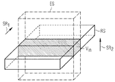
既に上述したように、内部ボリュームリフォーカス法において、スラブ励起高周波パルス(スラブ励起高周波パルスはこのスラブ励起高周波パルスに合わせて印加される傾斜磁場を伴う)と、後続のリフォーカス高周波パルス(リフォーカス高周波パルスは第1方向に対して垂直に向く方向の傾斜磁場を伴う)との的確な選択によって、両選択方向において制限された視野ボリュームVinが励起される。このことが模範的に図2に示されている。視野ボリュームVin(「内部ボリューム」とも、又はしばしば「撮像視野」(Field of View)又は略して「FoV」とも呼ばれる)は、スラブ励起高周波パルスによって選択的に励起されるボリュームESと、リフォーカス高周波パルスによって選択的に励起されるリフォーカススライスRSとの交差領域によって生じる。第3の方向において、この内部ボリュームVinは読み出しエンコードによって制限される。 As already described above, in the internal volume refocus method, the slab excitation radio frequency pulse (the slab excitation radio frequency pulse is accompanied by a gradient magnetic field applied in accordance with the slab excitation radio frequency pulse) and the subsequent refocus radio frequency pulse (refocus The precise selection of the high-frequency pulse (with a gradient magnetic field oriented perpendicular to the first direction) excites a limited field volume Vin in both selected directions. This is exemplarily shown in FIG. The field volume V in (also called “internal volume” or often “Field of View” or “FoV” for short) is a volume ES that is selectively excited by slab-excited radio frequency pulses and refocusing. This is caused by the crossing region with the refocus slice RS that is selectively excited by the high frequency pulse. In the third direction, the internal volume V in is limited by the read encoded.
実際には、第1のスライス選択方向SR1および第2のスライス選択方向SR2を任意に置くことができる。しかし、通常、これらの方向はプロトコルによって決定されており、大概は、スラブ励起高周波パルスによってスライス選択が行われる第1の選択方向SR1がz方向に向き、これに垂直な第2の選択方向SR2がy方向に向いている。これらの選択方向SR1,SR2を決定する(第1の選択方向パラメータとしての)スライス選択方向パラメータSRPおよび(第2の選択方向パラメータとしての)リフォーカス方向パラメータRRPが、通常はその他の制御パラメータSPと一緒に共通に、例えば図1に示されているように、(選択方向パラメータインターフェース24も成す)インターフェース24を介して制御シーケンス決定装置22によって受信される。さらに、付属のグラフィカルユーザインターフェースを有するターミナル20のコンピュータ21を介して、操作者は視野ボリュームサイズパラメータ値dx,dy,dz、即ち視野ボリュームVinの長さ、幅および高さを決定することができる。場合によっては、相応のパラメータを既にプロトコルP内の制御パラメータSPによって規定しておき、操作者が視野ボリュームサイズパラメータ値dx,dy,dzを変更することができるようにしてもよい。適切なインターフェース装置23を介して、制御シーケンス決定装置22は、この視野ボリュームのサイズパラメータ値dx,dy,dzを受信することができる。
Actually, the first slice selection direction SR 1 and the second slice selection direction SR 2 can be arbitrarily set. Usually, however, these directions are determined by the protocol. In general, the first selection direction SR 1 in which slice selection is performed by the slab excitation high-frequency pulse is oriented in the z direction, and the second selection direction perpendicular thereto. SR 2 is in the y direction. The slice selection direction parameter SRP (as the first selection direction parameter) and the refocus direction parameter RRP (as the second selection direction parameter) that determine these selection directions SR 1 , SR 2 are usually other controls. In common with the parameter SP, it is received by the control
図3および図4には、患者Oの大まかに模式的に示された上半身内の典型的な視野ボリュームVinの例が示されている。上半身は、一般にz方向、即ちトモグラフィ装置の長手軸の方向に向けられる。図3は上半身を上から見た平面図、図4はz方向に対して垂直な断面図を示す。ユーザインターフェースにより、操作者は視野ボリュームVinのサイズ、即ちz方向の幅dz、y方向の幅dyおよびx方向の幅dxを入力することができる。このために、操作者に対して一般に概観画像がコンピュータ21のモニターに表示され、グラフィカルユーザインターフェースによって、操作者が視野ボリュームVinを描き入れることができるので、概観表示において選定された範囲に適合する適切な視野ボリュームサイズパラメータ値dx,dy,dzが自動的に生成される。これが図3および図4にも示されているように、大抵の操作者は、歴史的理由から視野ボリュームVinを、相対的にz方向に狭くy方向およびx方向に著しく長くなるように選定する。これは、次のことに根ざしている。即ち、操作者は、従来のマルチスライス応用による伝統的なやり方で個別の薄いスライスを選択し、各スライスおいて画像を作成し、しかもz軸に対して垂直な断層画像を生成することに慣れていることである。実際には、3次元励起の場合に視野ボリュームVinのこの種のサイズ選択は全く必要でなく、むしろスラブが同じように略z方向に平行であり、即ちy方向に最も狭い幅を有することができる。
3 and 4 show an example of a typical visual field volume Vin in the upper body schematically shown by a patient O. The upper body is generally oriented in the z direction, i.e. in the direction of the longitudinal axis of the tomography device. 3 is a plan view of the upper body viewed from above, and FIG. 4 is a cross-sectional view perpendicular to the z direction. A user interface, the operator can input the size of the viewing volume V in, i.e. z-direction width dz, the width dy and x width dx in the y direction. For this, in general overview image is displayed on the monitor of the
しかし、従来の方法において、z方向およびy方向の視野ボリュームサイズパラメータ値dz,dyが、z方向の幅をy方向の幅よりも狭くするように選ばれると同時に、従来のプロトコルにおいて予定されているように、第1の選択方向SR1がz方向に、第2の選択方向SR2がy方向に置かれるならば、このことが、大抵は次の結果を招く。即ち、視野ボリュームVinの幅dyの全体にわたって十分なサンプリングを達成するためには、リフォーカス高周波パルスを送出する際に、第2の選択方向SR2の傾斜磁場振幅を極端に低く選ばなければならないという結果である。 However, in the conventional method, the field volume size parameter values dz and dy in the z direction and the y direction are selected so that the width in the z direction is narrower than the width in the y direction, and at the same time, it is scheduled in the conventional protocol. As such, if the first selection direction SR 1 is placed in the z direction and the second selection direction SR 2 is placed in the y direction, this usually results in: That is, in order to achieve adequate sampling over the entire width dy of the viewing volume V in, at the time of sending the refocusing RF pulses, to be chosen extremely low second gradient amplitude selection direction SR 2 It is the result of not becoming.
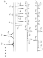
内部ボリュームリフォーカシングを用いる相応の3Dターボスピンエコーシーケンス(TSEシーケンス)AS'のシーケンスダイアグラムが図5に示されている。このパルスダイアグラムでは、通常のように時間tに対して、高周波パルスおよび読み出し時間枠が示され、またそれに協調して印加されるべき傾斜磁場が異なる重なり合う時間軸上に示されている。図5はパルスシーケンスAS’の始まりだけを示す。 A sequence diagram of a corresponding 3D turbo spin echo sequence (TSE sequence) AS ′ using internal volume refocusing is shown in FIG. In this pulse diagram, a high-frequency pulse and a readout time frame are shown with respect to time t as usual, and gradient magnetic fields to be applied in cooperation therewith are shown on different overlapping time axes. FIG. 5 shows only the beginning of the pulse sequence AS '.
上段の時間軸上には高周波パルスHFS,HFRおよび読み出し時間枠W1,W2,W3が示され、その下の時間軸上には読み出し方向の傾斜磁場パルスGR1,GR2,GR3,GR4が示され、3段目の時間軸上には古典的な位相エンコード方向の傾斜磁場パルスGP1’,GP2’,GP3’,GP4’,GP5’,GP6’,GP7’,GP8’,GP9’,GP10’が示され、最下段の時間軸上にはスライス選択方向(ここではz方向)の傾斜磁場パルスGS1’,GS2’,GS3’,GS4’,GS5’,GS6’,GS7’,GS8’,GS9’,GS10’,GS11’が示されている。 Upper frequency pulse HF S is on the time axis, HF R and read time window W 1, W 2, W 3 are shown, gradient pulses GR 1 read direction on the time axis of the underlying, GR 2, GR 3 and GR 4 are shown, and the gradient magnetic field pulses GP 1 ′, GP 2 ′, GP 3 ′, GP 4 ′, GP 5 ′, GP 5 ′, GP 6 in the classical phase encoding direction are shown on the third stage time axis. , GP 7 ′, GP 8 ′, GP 9 ′, GP 10 ′ are shown, and gradient magnetic field pulses GS 1 ′, GS 2 ′ in the slice selection direction (z direction in this case) are displayed on the bottom time axis. GS 3 ′, GS 4 ′, GS 5 ′, GS 6 ′, GS 7 ′, GS 8 ′, GS 9 ′, GS 10 ′, GS 11 ′ are shown.
このパルスダイアグラムで認識できるように、スラブ励起高周波パルスHFSとスライス選択方向に平行に印加される傾斜磁場GS2’とからなる第1のパルス配列PA1’は、スライス選択方向、即ちここではz方向の1つのスライスを選択的に励起する。この傾斜磁場パルスGS2’の前に印加された傾斜磁場パルスGS1’は、以前の励起の残留信号をディフェーズするためのスポイラー傾斜磁場である。傾斜磁場パルスGS3’,GS4’はリフェーズ傾斜磁場である。スライス選択傾斜磁場GS2’によって信号が(各傾斜磁場によるのと同様に)ディフェーズされ、スライス選択後に再びリフェーズされなければならない。通常は傾斜磁場パルスGS3’,GS4’が合わせて傾斜磁場パルスGS2’の半分の面積を持つことが必要である。傾斜磁場パルスGS4’はリフォーカス高周波パルスの後に印加されるので、傾斜磁場パルスGS4’は傾斜磁場パルスGS3’とは異なる符号を持つ。 As can be recognized in this pulse diagram, the first pulse array PA 1 ′ composed of the slab excitation high-frequency pulse HF S and the gradient magnetic field GS 2 ′ applied in parallel to the slice selection direction is in the slice selection direction, that is, here. Selectively excite one slice in the z direction. The gradient magnetic field pulse GS 1 ′ applied before this gradient magnetic field pulse GS 2 ′ is a spoiler gradient magnetic field for dephasing the residual signal of the previous excitation. The gradient magnetic field pulses GS 3 ′ and GS 4 ′ are rephase gradient magnetic fields. The signal must be dephased (as with each gradient) by the slice selection gradient GS 2 'and rephased again after slice selection. Normally, it is necessary that the gradient magnetic field pulses GS 3 ′ and GS 4 ′ have a half area of the gradient magnetic field pulse GS 2 ′. Since the gradient magnetic field pulse GS 4 ′ is applied after the refocusing high frequency pulse, the gradient magnetic field pulse GS 4 ′ has a different sign from the gradient magnetic field pulse GS 3 ′.
続いて、位相エンコード方向、即ちここではy方向の傾斜磁場パルスGP2’が並行して付き添っているリフォーカス高周波パルスHFRを含む第2のパルス配列PA2’が送出される。位相エンコード方向のこの傾斜磁場GP2’は、リフォーカス高周波パルスも選択的に作用するようにする。それゆえに、図2に示されているように、他のエンコードを内部ボリュームVinに限定することができる。その際に、第1のパルス配列PA1’および第2のパルス配列PA2’、特に傾斜磁場パルスGS2’,GP2’は、視野領域つまり内部ボリュームVinのサイズが各方向において使用者によって設定されたサイズに正確に一致するように選ばれる。 Subsequently, a phase encoding direction, i.e. where the 'second pulse sequence PA 2 comprising refocusing RF pulse HF R which is accompanied in parallel' gradient pulse GP 2 in the y direction is sent. This gradient magnetic field GP 2 ′ in the phase encoding direction causes the refocusing radio frequency pulse to act selectively. Therefore, as shown in FIG. 2, it is possible to limit the other encoded the internal volume V in. At that time, the first pulse array PA 1 ′ and the second pulse array PA 2 ′, in particular the gradient magnetic field pulses GS 2 ′ and GP 2 ′, are used by the user in the size of the visual field region, that is, the internal volume Vin in each direction. Chosen to exactly match the size set by.
読み出し方向の他の傾斜磁場パルスGR1,GR2,GR3,GR4は次の機能を有する。傾斜磁場パルスGR1はディフェーズ傾斜磁場である。この傾斜磁場パルスGR1によって、信号が先ずディフェーズされ、その後読み出し時間枠(読み出し)期間中にリフェーズされる。それによって、信号最大値が正確に読み出しの中心において生じる。傾斜磁場GR2,GR3,GR4は通常の読み出し傾斜磁場である。 The other gradient magnetic field pulses GR 1 , GR 2 , GR 3 , GR 4 in the readout direction have the following functions. The gradient magnetic field pulse GR 1 is a dephase gradient magnetic field. By this gradient magnetic field pulse GR 1 , the signal is first dephased and then rephased during the readout time frame (readout) period. Thereby, the signal maximum occurs exactly at the center of the readout. The gradient magnetic fields GR 2 , GR 3 , GR 4 are normal readout gradient magnetic fields.
位相エンコード方向の傾斜磁場パルスGP1’,GP3’は、FIDアーチファクトを避けるためにリフォーカスパルスHFRを中心にして配置されたスポイラー傾斜磁場およびリフェーズ傾斜磁場である。 Gradient pulses GP 1 in the phase encoding direction ', GP 3' is a spoiler gradient magnetic field and rephasing gradient magnetic field which is arranged around the refocusing pulse HF R to avoid FID artifacts.
位相エンコード方向の他の傾斜磁場パルスGP4’,…,GP10’は通常の位相エンコード傾斜磁場である。スライス選択方向の他の傾斜磁場GS5’,…,GS11’はスライス選択方向の通常の位相エンコード傾斜磁場である。 The other gradient magnetic field pulses GP 4 ′,..., GP 10 ′ in the phase encode direction are normal phase encode gradient magnetic fields. The other gradient magnetic fields GS 5 ′,..., GS 11 ′ in the slice selection direction are normal phase encoding gradient magnetic fields in the slice selection direction.
図5から分かるように、リフォーカス高周波パルスHFRは、スラブ選択高周波パルスHFSよりも著しく長い。これは、リフォーカシングの際には、90°の目標フリップ角で足りるスラブ励起の際よりも著しく大きい、つまり145°〜180°の目標フリップ角を使用するからである。しかし、リフォーカス高周波パルスHFRの振幅は、種々の理由から、例えばシステム制約によるB1限界および/またはSAR理由から任意に高めることができないので、リフォーカス高周波パルスHFRを相応に長くせざるを得ない。上記理由から、このことは、特に、内部ボリュームもしくは視野範囲Vinにおけるy方向の著しく幅の広いサイズ(これは、既に図4に基づいて説明したように操作者により設定される)との合計で、位相エンコード方向、即ちy方向の傾斜磁場パルスGP2’を極めて少なく選ばなければならないという結果をもたらす。このことは、またしてもB0不均一性および化学シフトに基づく作用に関する高い敏感性をもたらすので、脂肪組織による折り返しアーチファクトの確率が高くなる。 As it can be seen from FIG. 5, refocusing RF pulse HF R is significantly longer than the slab select RF pulse HF S. This is because during refocusing, a target flip angle of 145 ° to 180 ° is used, which is significantly greater than slab excitation, which requires a target flip angle of 90 °. However, the amplitude of the refocusing high-frequency pulse HF R cannot be increased arbitrarily for various reasons, for example, due to the B 1 limit due to system constraints and / or the SAR reason, so the refocusing high-frequency pulse HF R must be lengthened accordingly. I do not get. For the above reasons, this is especially the sum of the internal volume or the remarkably wide size in the y direction in the field of view range Vin (which is set by the operator as already explained with reference to FIG. 4). in the result that the phase encoding direction, i.e. must be chosen very small in the y direction of the gradient pulse GP 2 '. This again results in a high sensitivity for effects based on B 0 inhomogeneities and chemical shifts, increasing the probability of folding artifacts due to adipose tissue.
この問題を回避するために、本発明による方法において、第1の選択方向SR1および第2の選択方向SR2は、励起されるべき視野ボリュームVinのサイズの長さ比に応じて自動的に選択される。このためには、プロトコルによって予め与えられる制御パラメータSPと、使用者によって承認又は設定されるような視野ボリュームサイズパラメータ値dx,dy,dzとに基づいて制御シーケンスASを作成する通常の方法に、付加的な方法ステップを導入することで十分である。 To avoid this problem, in the method according to the invention, the first selection direction SR 1 and the second selection direction SR 2 automatically according to the length ratio of the size of the viewing volume V in to be excited Selected. For this purpose, a normal method of creating the control sequence AS based on the control parameter SP given in advance by the protocol and the visual field volume size parameter values dx, dy, dz as approved or set by the user, It is sufficient to introduce additional method steps.
このことを以下において図6に基づいて説明する。第1の方法ステップIにおいて、通常の方法でスライス選択方向パラメータSRP(即ち、ここではスラブ選択方向パラメータ)およびリフォーカス方向パラメータRRPが獲得され、例えばプロトコルから受け取られる。さらに視野ボリュームサイズパラメータ値dx,dy,dzが獲得される。これは、図1による実施例では、既に述べたようにインターフェース23,24により行われる。
This will be described below with reference to FIG. In a first method step I, a slice selection direction parameter SRP (ie here a slab selection direction parameter) and a refocus direction parameter RRP are obtained and received from the protocol, for example, in a conventional manner. Further, visual field volume size parameter values dx, dy, dz are obtained. In the embodiment according to FIG. 1, this is done by the
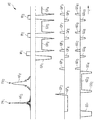
これらのデータは方向規定ユニット26に伝送される。この方向規定ユニット26は方向パラメータ検査ユニット27を有し、この方向パラメータ検査ユニット27は、第1の選択方向SR1および第2の選択方向SR2が視野ボリュームサイズに関して予め与えられた条件に適合するか否かを検査する。このことが図6において方法ステップIIに示されている。具体的には、ここでは古典的な位相エンコード方向、即ちy方向の幅もしくは視野ボリュームサイズパラメータ値dyが、古典的なスラブ選択方向、即ちz方向の幅もしくは視野ボリュームサイズパラメータ値dzよりも大きいか否かが検査される。さらに、スライス選択方向パラメータSRPが同様にz方向にあるように選ばれているか否かが検査される。この古典的な組み合わせが与えられている場合には、即ち、視野ボリュームVinの広がり方向に関してリフォーカス高周波パルスHFRがスラブ励起高周波パルスHFSよりも長い広がり方向に選択的に作用しなければならないように、使用者によって視野ボリュームVinのサイズが選ばれ、かつプロトコルによって第1の選択方向SR1および第2の選択方向SR2が規定されている場合には(図6における分岐“y”)、ステップIIIにおいて、スライス選択方向パラメータSRPおよびリフォーカス方向パラメータRRPは、スライス選択方向がy方向に向きかつリフォーカス方向がz方向に向くように変更される。それによって、自動的に、スラブ選択高周波パルスHFSはy方向、即ち古典的な位相エンコード方向にだけ作用し、そしてリフォーカス高周波パルスHFRはスライス選択方向、即ちz方向にだけ作用する。方向パラメータSRPおよびリフォーカス方向パラメータRRPのこの交換は、例えば、方向パラメータ検査ユニット27の結果を受け取る方向規定ユニット26の方向パラメータ変更ユニット28において実行することができる。
These data are transmitted to the
ステップIIにおける検査の際に両条件のうちの1つが満たされていないことが明らかである場合、それは、(偶然に)操作者がもともと、z方向のサイズがy方向のサイズよりも大きくなるように視野ボリュームVinを選んだことに起因する。この場合には(図6における分岐“n”)、選択方向パラメータSRPおよびリフォーカス方向パラメータRRPの変更もしくは交換を行う必要はない。 If it is clear during inspection in step II that one of the two conditions is not met, it is (by chance) that the operator originally has a size in the z direction that is larger than the size in the y direction. due to the fact that chose the viewing volume V in to. In this case (the branch “n” in FIG. 6), it is not necessary to change or exchange the selection direction parameter SRP and the refocus direction parameter RRP.
そのように自動的に最適化された選択方向パラメータSRPおよびリフォーカス方向パラメータRRPを用いて従来の方法により制御シーケンスASを決定することができる。 The control sequence AS can be determined by the conventional method using the selection direction parameter SRP and the refocus direction parameter RRP that are automatically optimized as described above.
制御シーケンスの決定はパルス配列決定ユニット29において行われる。
The control sequence is determined in the pulse
図7は、図5における制御シーケンスAS’に類似した制御シーケンスASを有する相応のパルスダイアグラムを示すが、しかしここでは、第1の選択方向SR1および第2の選択方向SR2が視野ボリュームVinの、使用者によって選択されたサイズを考慮して選ばれるという趣旨で、第1のパルス配列PA1および第2のパルス配列PA2が、本発明による方法により最適化される。このことは、ここではスラブ励起高周波パルスHFSに並行して、もはやスライス選択方向、即ちz方向の傾斜磁場が送出されずに、その代わりに古典的な位相エンコード方向、即ちy方向の傾斜磁場GP1が送出されることをもたらす。従って、ここでは、著しく低い目標フリップ角さえ達成すればよいスラブ励起高周波パルスHFSが、視野ボリュームVinの長いほうの広がり方向に選択的に作用しなければならない(図3における視野ボリュームVinのz方向の広がりに比べたy方向の広がり、図4参照)。しかし、これは問題ではない。というのはスラブ励起高周波パルスHFSが90°の目標フリップ角さえ達成すればよいからである。それとは異なり、制御シーケンスASのパルス配列PA2は、リフォーカス高周波パルスHFRに並行して今やスライス選択方向、即ち、z方向の傾斜磁場パルスGS3が送出されるように選ばれている。リフォーカス高周波パルスHFRは比較的少ない広がりdzにわたって選択的に作用しさえすればよい。このことは、スライス選択方向zの該傾斜磁場パルスGS3が、従来において位相エンコード方向に投入される傾斜磁場パルスGP2’(図5参照)よりも高く選ぶことができるということをもたらす。従って、全体として、制御シーケンスASがB0不均一性に対して、また特に化学シフトに対して敏感でなくなるので、高い確率で折り返しアーチファクトを回避することができる。 FIG. 7 shows a corresponding pulse diagram with a control sequence AS similar to the control sequence AS ′ in FIG. 5, but here the first selection direction SR 1 and the second selection direction SR 2 have a field volume V the in, the effect that is selected in consideration of the selected size by the user, the first pulse sequence PA 1 and a second pulse sequence PA 2, are optimized by the method according to the invention. This means that in parallel with the slab excitation radio frequency pulse HF S , the gradient field in the slice selection direction, ie the z direction, is no longer delivered, but instead the classical phase encoding direction, ie the gradient field in the y direction. GP 1 is sent out. Therefore, here, the slab excitation radio frequency pulse HF S, which only needs to achieve a very low target flip angle, must act selectively in the longer spreading direction of the field volume Vin (view field volume Vin in FIG. 3). The spread in the y direction compared to the spread in the z direction, see FIG. But this is not a problem. This is because the slab excitation high frequency pulse HF S only needs to achieve a target flip angle of 90 °. Unlike that, the pulse sequence PA 2 of the control sequence AS is now the slice selection direction parallel to the refocusing RF pulse HF R, i.e., the gradient pulse GS 3 in the z direction is selected to be sent. The refocusing high frequency pulse HF R only needs to act selectively over a relatively small spread dz. This leads to the fact that the gradient magnetic field pulse GS 3 in the slice selection direction z can be selected higher than the gradient magnetic field pulse GP 2 ′ (see FIG. 5) conventionally applied in the phase encoding direction. Therefore, as a whole, the control sequence AS is less sensitive to B 0 inhomogeneities and in particular to chemical shifts, so that aliasing artifacts can be avoided with a high probability.
図7において、読み出し方向GR1,GR2,GR3,GR4は、ここでも、上記において図5に対して述べたと同じ機能を有する。同様に位相エンコード方向の傾斜磁場パルスGP2,GP3ならびに傾斜磁場パルスGS1,GS3,GS4は、上記の説明と同様に、スポイラー傾斜磁場もしくはリフォーカス傾斜磁場として用いられる。位相エンコード方向の他の傾斜磁場GP4,…,GP10ならびにスライス選択方向の他の傾斜磁場GP4,…,GP11も、またしても通常の位相エンコード傾斜磁場である。 In FIG. 7, the read directions GR 1 , GR 2 , GR 3 , GR 4 again have the same function as described above for FIG. Similarly, the gradient magnetic field pulses GP 2 , GP 3 and the gradient magnetic field pulses GS 1 , GS 3 , GS 4 in the phase encoding direction are used as a spoiler gradient magnetic field or a refocus gradient magnetic field in the same manner as described above. Other gradient GP 4 in the phase encoding direction, ..., GP 10 and the slice selection direction other gradient GP 4, ..., GP 11 also be also a normal phase encoding gradient magnetic field.
ここで指摘しておくに、第3の方向、即ち読み出し方向を考慮した最適化も行い得ることは自明である。このために方法ステップIIおよびIIIを相応に変更することだけが必要であり、その際に、読み出し方向においてはサンプリングを相応に高めるのに時間がかからないことから、読み出し方向は常に、使用者によって選択された視野ボリュームの最長のサイズに相当するように置かれる。 As pointed out here, it is obvious that optimization in consideration of the third direction, that is, the reading direction can also be performed. For this, it is only necessary to change method steps II and III accordingly, in which case the reading direction is always selected by the user since it does not take time to increase the sampling accordingly. Placed so as to correspond to the longest size of the visual field volume.
この本発明による方法の特別な利点は、従来の方法を、図6に示す方法ステップIIおよびIIIに関して補足するだけでよく、その他の点では方法又は既存のプロトコルにおいてそれ以上の変更を行う必要がないことにある。さらに、この本発明による方法は、追加のハードウェアを必要としないという利点も有する。原理的には、従来において公知のMR装置の全てに、従って1つのみの送信チャンネルを有するシステムにもpTXシステムにも適用することができる。 This particular advantage of the method according to the invention is that the conventional method only needs to be supplemented with respect to the method steps II and III shown in FIG. 6, otherwise there is a need to make further changes in the method or existing protocols. There is nothing. Furthermore, this method according to the invention also has the advantage that no additional hardware is required. In principle, it can be applied to all conventionally known MR devices and thus to systems with only one transmission channel as well as pTX systems.
最後にもう一度指摘しておくに、上記において詳細に説明した方法および構造は、実施例であって、請求項によって設定されている限り本発明の範囲を逸脱することなく広範に当業者によって変更可能である。例えば制御シーケンス決定装置22は、ターミナル上で実現する代わりに、制御装置10自体の一部として、特に測定制御ユニット15の構成要素として実現することもできる。同様に、制御シーケンス決定装置は、例えばネットワークNWを介して磁気共鳴装置1に接続されている別個のコンピュータシステム上でも実現することができる。念のために指摘しておくに、「1つの」なる表現は、該当する特徴事項が複数も存在することを排除するものではない。同様に用語「ユニット」および「モジュール」は、これらが場合によっては空間的にも分散させられた複数の構成要素から構成されていることを排除するものではない。
Finally, it should be pointed out once again that the methods and structures described in detail above are examples and can be varied widely by a person skilled in the art without departing from the scope of the invention as long as they are defined by the claims. It is. For example, instead of being realized on the terminal, the control
1 磁気共鳴装置
2 磁気共鳴スキャナ
3 基本磁場磁石
4 傾斜磁場システム
5 全身高周波コイル
6 局所コイル装置
7 患者用テーブル
8 検査空間(患者用トンネル)
10 制御装置
11 傾斜磁場制御ユニット
12 高周波送信ユニット
13 高周波受信ユニット
14 再構成ユニット
15 測定制御ユニット
16 記憶装置
17 インターフェース
18 インターフェース
20 ターミナル
21 コンピュータ
22 制御シーケンス決定装置
23 インターフェース装置
24 インターフェース
25 制御シーケンス出力インターフェース
26 方向規定ユニット
27 方向パラメータ検査ユニット
28 方向パラメータ変更ユニット
29 パルス配列決定装置
AS 制御シーケンス
BD 画像データ
GS 傾斜磁場パルスシーケンス
HFS 高周波パルスシーケンス
NW ネットワーク
O 検査対象(患者)
P 制御プロトコル
RD 生データ
RRP リフォーカス方向パラメータ
RS リフォーカス
SP 制御パラメータ値
SRP スライス選択方向パラメータ
Vin 視野ボリューム
DESCRIPTION OF
DESCRIPTION OF
P Control protocol RD Raw data RRP Refocus direction parameter RS Refocus SP Control parameter value SRP Slice selection direction parameter V in visual field volume
Claims (9)
励起されるべき視野ボリューム(Vin)の空間的な広がりを規定する視野ボリュームサイズパラメータ値(dx,dy,dz)が獲得され、
その後、第1の選択方向(SR1)および第2の選択方向(SR2)が、互いに異なる選択方向(SR1,SR2)において励起されるべき視野ボリューム(Vin)の空間的な広がりの長さ比に応じて自動的に決定され、
第1のパルス配列(PA 1 ,PA 1 ’)がスラブ励起高周波パルス(HF S )を含み、
第2のパルス配列(PA 2 ,PA 2 ’)がリフォーカス高周波パルス(HF R )を含み、
スラブ励起高周波パルス(HF S )の目標フリップ角がリフォーカス高周波パルス(HF R )の目標フリップ角よりも小さい磁気共鳴制御シーケンスの決定方法。 At least one first pulse arrangement (PA 1 , PA 1 ′) acting spatially in the first selection direction (SR 1 ) and spatially selective in the second selection direction (SR 2 ). A method for determining a magnetic resonance control sequence (AS) having a subsequent second pulse sequence (PA 2 , PA 2 ′),
A field volume size parameter value (dx, dy, dz) that defines the spatial extent of the field volume (V in ) to be excited is obtained;
Thereafter, the first selection direction (SR 1 ) and the second selection direction (SR 2 ) are spatially expanded in the view volume (V in ) to be excited in the different selection directions (SR 1 , SR 2 ). Automatically determined according to the length ratio of
The first pulse sequence (PA 1 , PA 1 ′) includes slab excitation radio frequency pulses (HF S ),
The second pulse sequence (PA 2 , PA 2 ′) includes a refocusing high frequency pulse (HF R ),
A method of determining a magnetic resonance control sequence in which a target flip angle of a slab excitation high frequency pulse (HF S ) is smaller than a target flip angle of a refocus high frequency pulse (HF R ) .
第1の選択方向(SR1)および第2の選択方向(SR2)が、互いに異なる選択方向(SR1,SR2)において励起されるべき視野ボリューム(Vin)の空間的な広がりの長さ比に応じて設定されている条件に適合しない場合に、第1の選択方向パラメータ(SRP)および第2の選択方向パラメータ(RRP)が自動的に変更される請求項1記載の方法。 A first selection direction parameter (SRP) defining a first selection direction (SR 1 ) and a second selection direction parameter (RRP) defining a second selection direction (SR 2 ) are obtained;
The first selection direction (SR 1 ) and the second selection direction (SR 2 ) are the length of the spatial extension of the field volume (V in ) to be excited in the different selection directions (SR 1 , SR 2 ). set if that does not conform to it and conditions the method of claim 1, wherein the first selection direction parameter (SRP) and the second selection direction parameter (RRP) is automatically changed in accordance with the ratio.
その後この磁気共鳴制御シーケンス(AS)を利用して磁気共鳴システム(1)を動作させる磁気共鳴システム(1)の動作方法。 First determine the magnetic resonance control sequence (AS) by a method according to one of claims 1 to 4,
Thereafter, the magnetic resonance system (1) is operated by using the magnetic resonance control sequence (AS) to operate the magnetic resonance system (1).
励起されるべき視野ボリューム(Vin)の空間的な広がりを規定する視野ボリュームサイズパラメータ値(dx,dy,dz)を獲得するための入力インターフェース装置(23)と、
互いに異なる選択方向(SR1,SR2)において励起されるべき視野ボリューム(Vin)の空間的な広がりの長さ比に応じて第1の選択方向(SR1)および第2の選択方向(SR2)を自動的に決定するように構成されている方向規定ユニット(26)と、
視野ボリュームサイズパラメータ値(dx,dy,dz)と決定された第1の選択方向(SR1)および第2の選択方向(SR2)とを考慮してパルス配列(PA1,PA1',PA2,PA2’)を決定するためのパルス配列決定ユニット(29)と、を有し、
第1のパルス配列(PA 1 ,PA 1 ’)がスラブ励起高周波パルス(HF S )を含み、
第2のパルス配列(PA 2 ,PA 2 ’)がリフォーカス高周波パルス(HF R )を含み、
スラブ励起高周波パルス(HF S )の目標フリップ角がリフォーカス高周波パルス(HF R )の目標フリップ角よりも小さい制御シーケンス決定装置(22)。 At least one first pulse arrangement (PA 1 , PA 1 ′) acting spatially in the first selection direction (SR 1 ) and spatially selective in the second selection direction (SR 2 ). A control sequence determination device (22) for determining a magnetic resonance control sequence (AS) including a subsequent second pulse sequence (PA 2 , PA 2 ′),
An input interface device (23) for obtaining a field volume size parameter value (dx, dy, dz) that defines the spatial extent of the field volume (V in ) to be excited;
The first selection direction (SR 1 ) and the second selection direction (depending on the length ratio of the spatial extent of the field volume (V in ) to be excited in different selection directions (SR 1 , SR 2 ) SR 2 ), a direction defining unit (26) configured to automatically determine;
Considering the field volume size parameter value (dx, dy, dz) and the determined first selection direction (SR 1 ) and second selection direction (SR 2 ), the pulse arrangement (PA 1 , PA 1 ′, A pulse sequencing unit (29) for determining PA 2 , PA 2 ′) ,
The first pulse sequence (PA 1 , PA 1 ′) includes slab excitation radio frequency pulses (HF S ),
The second pulse sequence (PA 2 , PA 2 ′) includes a refocusing high frequency pulse (HF R ),
A control sequence determination device (22) in which the target flip angle of the slab excitation high-frequency pulse (HF S ) is smaller than the target flip angle of the refocus high-frequency pulse (HF R ).
第1の選択方向(SR1)および第2の選択方向(SR2)が、互いに異なる選択方向(SR1,SR2)において励起されるべき視野ボリューム(Vin)の空間的な広がりの長さ比に応じて予め与えられた条件に適合しているか否かを検査する方向パラメータ検査ユニット(27)と、
第1の選択方向(SR1)および第2の選択方向(SR2)が予め与えられた条件に適合しない場合に、第1の選択方向パラメータ(SRP)および第2の選択方向パラメータ(RRP)を自動的に変更する方向パラメータ変更ユニット(28)と、
を有する請求項6記載の制御シーケンス決定装置(22)。 Selection direction for obtaining a first selection direction parameter (SRP) defining a first selection direction (SR 1 ) and a second selection direction parameter (RRP) defining a second selection direction (SR 2 ) A parameter interface (24);
The first selection direction (SR 1 ) and the second selection direction (SR 2 ) are the length of the spatial extension of the field volume (V in ) to be excited in the different selection directions (SR 1 , SR 2 ). A direction parameter inspection unit (27) for inspecting whether or not a predetermined condition is met according to the thickness ratio;
The first selection direction parameter (SRP) and the second selection direction parameter (RRP) when the first selection direction (SR 1 ) and the second selection direction (SR 2 ) do not meet a predetermined condition. A direction parameter changing unit (28) for automatically changing
The control sequence determination device (22) according to claim 6, comprising:
磁気共鳴制御シーケンスを決定して、その磁気共鳴制御シーケンスを制御装置(15)に伝送するために請求項6又は7記載の制御シーケンス決定装置(22)を有することを特徴とする磁気共鳴システム(1)。 A high-frequency transmission device (6), a gradient magnetic field system (4), and a high-frequency pulse train are transmitted to perform a desired measurement based on a magnetic resonance control sequence (AS) given in advance, and the gradient magnetic field system cooperates therewith. A magnetic resonance system (1) having a controller (15) configured to deliver a gradient magnetic field pulse train (GP) via
Magnetic resonance system comprising a control sequence determination device (22) according to claim 6 or 7 for determining a magnetic resonance control sequence and transmitting the magnetic resonance control sequence to the control device (15). 1).
Storage of the control sequence determination device (22) having program code parts for executing all the steps of the method according to one of claims 1 to 5 when executed in the control sequence determination device (22) A computer program that can be loaded into the device.
Applications Claiming Priority (2)
| Application Number | Priority Date | Filing Date | Title |
|---|---|---|---|
| DE102013207390.9 | 2013-04-24 | ||
| DE102013207390.9A DE102013207390B4 (en) | 2013-04-24 | 2013-04-24 | Determining a magnetic resonance drive sequence with an automatic adaptation of a first and a second selection direction |
Publications (3)
| Publication Number | Publication Date |
|---|---|
| JP2014213207A JP2014213207A (en) | 2014-11-17 |
| JP2014213207A5 JP2014213207A5 (en) | 2017-04-13 |
| JP6270609B2 true JP6270609B2 (en) | 2018-01-31 |
Family
ID=51684945
Family Applications (1)
| Application Number | Title | Priority Date | Filing Date |
|---|---|---|---|
| JP2014089218A Active JP6270609B2 (en) | 2013-04-24 | 2014-04-23 | Determination of magnetic resonance control sequence |
Country Status (5)
| Country | Link |
|---|---|
| US (1) | US9702952B2 (en) |
| JP (1) | JP6270609B2 (en) |
| KR (1) | KR101655126B1 (en) |
| CN (1) | CN104122519B (en) |
| DE (1) | DE102013207390B4 (en) |
Families Citing this family (5)
| Publication number | Priority date | Publication date | Assignee | Title |
|---|---|---|---|---|
| DE102013220301B4 (en) * | 2013-10-08 | 2015-07-16 | Siemens Aktiengesellschaft | Determining a drive sequence for a magnetic resonance imaging system using a feasibility criterion |
| DE102016200549A1 (en) | 2016-01-18 | 2017-07-20 | Siemens Healthcare Gmbh | Method for setting an MRI sequence |
| CN108020796B (en) * | 2016-10-31 | 2021-10-29 | 西门子(深圳)磁共振有限公司 | Magnetic resonance diffusion weighted imaging method and device |
| EP3535595B1 (en) * | 2016-11-07 | 2024-01-03 | Oxford University Innovation Limited | Correction method for magnetic resonance t1-mapping of visceral organs in the presence of elevated iron and elevated fat levels, and in the presence of off-resonance frequencies |
| JP6996985B2 (en) * | 2018-01-10 | 2022-01-17 | キヤノンメディカルシステムズ株式会社 | Magnetic resonance imaging device |
Family Cites Families (21)
| Publication number | Priority date | Publication date | Assignee | Title |
|---|---|---|---|---|
| JPS61275645A (en) * | 1985-05-31 | 1986-12-05 | Shimadzu Corp | Data gathering method for mri device |
| JPS62224337A (en) * | 1985-12-28 | 1987-10-02 | 旭化成株式会社 | Image information lead-out method using nuclear magnetic resonance |
| JPS62217950A (en) * | 1986-03-18 | 1987-09-25 | 横河メディカルシステム株式会社 | Nmr imaging apparatus |
| JPS6354155A (en) * | 1986-08-25 | 1988-03-08 | 旭化成株式会社 | Method for obtaining nuclear magnetic resonance information |
| JP2874927B2 (en) * | 1990-01-09 | 1999-03-24 | 株式会社東芝 | MRI equipment |
| JPH04108427A (en) * | 1990-08-29 | 1992-04-09 | Hitachi Ltd | Very high speed photographic method for mri part area and magnetic resonance diagnostic device based thereon |
| US5270654A (en) * | 1991-07-05 | 1993-12-14 | Feinberg David A | Ultra-fast multi-section MRI using gradient and spin echo (grase) imaging |
| JP3839992B2 (en) * | 1999-03-31 | 2006-11-01 | 株式会社東芝 | Magnetic resonance imaging system |
| US6541971B1 (en) * | 2001-06-28 | 2003-04-01 | Koninklijke Philips Electronics, N.V. | Multi-dimensional spatial NMR excitation |
| DE10203237B4 (en) * | 2002-01-28 | 2006-08-17 | Siemens Ag | Method for magnetic resonance imaging with automatic adjustment of the measuring field |
| JP4309632B2 (en) * | 2002-10-08 | 2009-08-05 | 株式会社東芝 | Magnetic resonance imaging system |
| DE102004026616B4 (en) * | 2004-06-01 | 2007-09-20 | Siemens Ag | Method for measuring an examination area with a magnetic resonance apparatus |
| CA2664770C (en) | 2006-09-29 | 2014-05-27 | Toray Industries, Inc. | Cell adsorption column |
| US8547101B2 (en) * | 2008-10-17 | 2013-10-01 | Hitachi Medical Corporation | Magnetic resonance imaging device |
| JP2010207568A (en) * | 2009-02-10 | 2010-09-24 | Toshiba Corp | Magnetic resonance imaging apparatus |
| US8085043B2 (en) * | 2009-04-03 | 2011-12-27 | Siemens Aktiengesellschaft | Method for image data acquisition with a magnetic resonance device |
| DE102010038777B4 (en) | 2010-08-02 | 2012-12-13 | Siemens Aktiengesellschaft | Creation of MR images of a predetermined volume section within an examination object with continuous table displacement |
| DE102011080215B4 (en) * | 2011-08-01 | 2013-02-28 | Siemens Aktiengesellschaft | Acquisition of MR data in a predetermined range |
| DE102011083398B4 (en) | 2011-09-26 | 2014-03-13 | Siemens Aktiengesellschaft | Generation of T2-weighted magnetic resonance images |
| DE102011083959B4 (en) | 2011-10-04 | 2021-02-25 | Siemens Healthcare Gmbh | Method for controlling a magnetic resonance system |
| US9851424B2 (en) * | 2012-01-30 | 2017-12-26 | Hitachi, Ltd. | Magnetic resonance imaging apparatus |
-
2013
- 2013-04-24 DE DE102013207390.9A patent/DE102013207390B4/en active Active
-
2014
- 2014-04-21 KR KR1020140047407A patent/KR101655126B1/en active IP Right Grant
- 2014-04-22 CN CN201410161995.XA patent/CN104122519B/en active Active
- 2014-04-23 JP JP2014089218A patent/JP6270609B2/en active Active
- 2014-04-24 US US14/260,609 patent/US9702952B2/en active Active
Also Published As
| Publication number | Publication date |
|---|---|
| CN104122519A (en) | 2014-10-29 |
| KR101655126B1 (en) | 2016-09-07 |
| KR20140127163A (en) | 2014-11-03 |
| JP2014213207A (en) | 2014-11-17 |
| US20140320127A1 (en) | 2014-10-30 |
| US9702952B2 (en) | 2017-07-11 |
| DE102013207390A1 (en) | 2014-10-30 |
| DE102013207390B4 (en) | 2015-03-05 |
| CN104122519B (en) | 2017-04-12 |
Similar Documents
| Publication | Publication Date | Title |
|---|---|---|
| US9684048B2 (en) | Optimization of a pulse sequence for a magnetic resonance system | |
| JP6406851B2 (en) | Magnetic resonance system operation sequence setting method, magnetic field distribution map analyzer, control sequence setting device, magnetic resonance system, and computer program | |
| US8938281B2 (en) | MR imaging using multi-channel RF excitation | |
| US9778339B2 (en) | Method and device for optimization of a pulse sequence for a magnetic resonance system | |
| JP6270609B2 (en) | Determination of magnetic resonance control sequence | |
| EP3044604B1 (en) | Metal resistant mr imaging | |
| KR20140001159A (en) | A system for simultaneous dual-slab acquisition of mr images | |
| JPWO2006117922A1 (en) | Magnetic resonance imaging device | |
| US7603157B2 (en) | Method and magnetic resonance imaging apparatus for compensating contrast inhomogeneities in magnetic resonance images | |
| US9159145B2 (en) | Fast dual contrast MR imaging | |
| US9846213B2 (en) | Optimization of the noise development of a 3D gradient echo sequence in a magnetic resonance system | |
| JP6762284B2 (en) | Magnetic resonance imaging device and noise removal method | |
| US8456163B2 (en) | Variable image resolution MR imaging system | |
| JP2006021023A (en) | Magnetic resonance diagnostic system | |
| US10156622B2 (en) | Method and apparatus for sectional optimization of radial MR pulse sequences | |
| US20180299524A1 (en) | Method and magnetic resonance apparatus for optimizing the simultaneous acquisition of magnetic resonance data from multiple slabs or slices | |
| US9535149B2 (en) | Method and apparatus for acquisition of magnetic resonance data | |
| US10048334B2 (en) | Test of a reordering algorithm of a spin echo magnetic resonance pulse sequence | |
| US9229083B2 (en) | Magnetic resonance method and system to generate an optimized MR image of an examination subject | |
| US9841478B2 (en) | Method and control device to operate a magnetic resonance system | |
| US10254366B2 (en) | Method and magnetic resonance apparatus for determining a pulse sequence | |
| US9500733B2 (en) | Method and apparatus for obtaining main magnetic field information and radio pulse related information in a magnetic resonance imaging system with different flip angles | |
| CN106443532B (en) | Optimization of layer orientation | |
| US10551463B2 (en) | Method and magnetic resonance apparatus for reconstructing an image from data acquired from a frequency-modulated balanced steady-state free precession sequence | |
| JP4208646B2 (en) | Magnetic resonance imaging system |
Legal Events
| Date | Code | Title | Description |
|---|---|---|---|
| A521 | Request for written amendment filed |
Free format text: JAPANESE INTERMEDIATE CODE: A523 Effective date: 20170310 |
|
| A621 | Written request for application examination |
Free format text: JAPANESE INTERMEDIATE CODE: A621 Effective date: 20170310 |
|
| A871 | Explanation of circumstances concerning accelerated examination |
Free format text: JAPANESE INTERMEDIATE CODE: A871 Effective date: 20170404 |
|
| A975 | Report on accelerated examination |
Free format text: JAPANESE INTERMEDIATE CODE: A971005 Effective date: 20170609 |
|
| A131 | Notification of reasons for refusal |
Free format text: JAPANESE INTERMEDIATE CODE: A131 Effective date: 20170620 |
|
| A521 | Request for written amendment filed |
Free format text: JAPANESE INTERMEDIATE CODE: A523 Effective date: 20170915 |
|
| TRDD | Decision of grant or rejection written | ||
| A01 | Written decision to grant a patent or to grant a registration (utility model) |
Free format text: JAPANESE INTERMEDIATE CODE: A01 Effective date: 20171205 |
|
| A61 | First payment of annual fees (during grant procedure) |
Free format text: JAPANESE INTERMEDIATE CODE: A61 Effective date: 20171226 |
|
| R150 | Certificate of patent or registration of utility model |
Ref document number: 6270609 Country of ref document: JP Free format text: JAPANESE INTERMEDIATE CODE: R150 |
|
| R250 | Receipt of annual fees |
Free format text: JAPANESE INTERMEDIATE CODE: R250 |
|
| S111 | Request for change of ownership or part of ownership |
Free format text: JAPANESE INTERMEDIATE CODE: R313113 |
|
| R250 | Receipt of annual fees |
Free format text: JAPANESE INTERMEDIATE CODE: R250 |
|
| R360 | Written notification for declining of transfer of rights |
Free format text: JAPANESE INTERMEDIATE CODE: R360 |
|
| R360 | Written notification for declining of transfer of rights |
Free format text: JAPANESE INTERMEDIATE CODE: R360 |
|
| R371 | Transfer withdrawn |
Free format text: JAPANESE INTERMEDIATE CODE: R371 |
|
| S111 | Request for change of ownership or part of ownership |
Free format text: JAPANESE INTERMEDIATE CODE: R313113 |
|
| R360 | Written notification for declining of transfer of rights |
Free format text: JAPANESE INTERMEDIATE CODE: R360 |
|
| R360 | Written notification for declining of transfer of rights |
Free format text: JAPANESE INTERMEDIATE CODE: R360 |
|
| R371 | Transfer withdrawn |
Free format text: JAPANESE INTERMEDIATE CODE: R371 |
|
| S111 | Request for change of ownership or part of ownership |
Free format text: JAPANESE INTERMEDIATE CODE: R313113 |
|
| R350 | Written notification of registration of transfer |
Free format text: JAPANESE INTERMEDIATE CODE: R350 |
|
| R250 | Receipt of annual fees |
Free format text: JAPANESE INTERMEDIATE CODE: R250 |
|
| R250 | Receipt of annual fees |
Free format text: JAPANESE INTERMEDIATE CODE: R250 |