JP6268076B2 - Leakage current correction in humid environment - Google Patents
Leakage current correction in humid environment Download PDFInfo
- Publication number
- JP6268076B2 JP6268076B2 JP2014234194A JP2014234194A JP6268076B2 JP 6268076 B2 JP6268076 B2 JP 6268076B2 JP 2014234194 A JP2014234194 A JP 2014234194A JP 2014234194 A JP2014234194 A JP 2014234194A JP 6268076 B2 JP6268076 B2 JP 6268076B2
- Authority
- JP
- Japan
- Prior art keywords
- current
- output current
- humidity sensor
- humidity
- increases
- Prior art date
- Legal status (The legal status is an assumption and is not a legal conclusion. Google has not performed a legal analysis and makes no representation as to the accuracy of the status listed.)
- Active
Links
Images


Classifications
-
- G—PHYSICS
- G03—PHOTOGRAPHY; CINEMATOGRAPHY; ANALOGOUS TECHNIQUES USING WAVES OTHER THAN OPTICAL WAVES; ELECTROGRAPHY; HOLOGRAPHY
- G03G—ELECTROGRAPHY; ELECTROPHOTOGRAPHY; MAGNETOGRAPHY
- G03G21/00—Arrangements not provided for by groups G03G13/00 - G03G19/00, e.g. cleaning, elimination of residual charge
- G03G21/20—Humidity or temperature control also ozone evacuation; Internal apparatus environment control
- G03G21/203—Humidity
-
- G—PHYSICS
- G01—MEASURING; TESTING
- G01N—INVESTIGATING OR ANALYSING MATERIALS BY DETERMINING THEIR CHEMICAL OR PHYSICAL PROPERTIES
- G01N27/00—Investigating or analysing materials by the use of electric, electrochemical, or magnetic means
-
- G—PHYSICS
- G03—PHOTOGRAPHY; CINEMATOGRAPHY; ANALOGOUS TECHNIQUES USING WAVES OTHER THAN OPTICAL WAVES; ELECTROGRAPHY; HOLOGRAPHY
- G03G—ELECTROGRAPHY; ELECTROPHOTOGRAPHY; MAGNETOGRAPHY
- G03G15/00—Apparatus for electrographic processes using a charge pattern
- G03G15/14—Apparatus for electrographic processes using a charge pattern for transferring a pattern to a second base
- G03G15/16—Apparatus for electrographic processes using a charge pattern for transferring a pattern to a second base of a toner pattern, e.g. a powder pattern, e.g. magnetic transfer
- G03G15/1665—Apparatus for electrographic processes using a charge pattern for transferring a pattern to a second base of a toner pattern, e.g. a powder pattern, e.g. magnetic transfer by introducing the second base in the nip formed by the recording member and at least one transfer member, e.g. in combination with bias or heat
- G03G15/167—Apparatus for electrographic processes using a charge pattern for transferring a pattern to a second base of a toner pattern, e.g. a powder pattern, e.g. magnetic transfer by introducing the second base in the nip formed by the recording member and at least one transfer member, e.g. in combination with bias or heat at least one of the recording member or the transfer member being rotatable during the transfer
- G03G15/1675—Apparatus for electrographic processes using a charge pattern for transferring a pattern to a second base of a toner pattern, e.g. a powder pattern, e.g. magnetic transfer by introducing the second base in the nip formed by the recording member and at least one transfer member, e.g. in combination with bias or heat at least one of the recording member or the transfer member being rotatable during the transfer with means for controlling the bias applied in the transfer nip
-
- G—PHYSICS
- G01—MEASURING; TESTING
- G01N—INVESTIGATING OR ANALYSING MATERIALS BY DETERMINING THEIR CHEMICAL OR PHYSICAL PROPERTIES
- G01N27/00—Investigating or analysing materials by the use of electric, electrochemical, or magnetic means
- G01N27/02—Investigating or analysing materials by the use of electric, electrochemical, or magnetic means by investigating impedance
- G01N27/04—Investigating or analysing materials by the use of electric, electrochemical, or magnetic means by investigating impedance by investigating resistance
- G01N27/12—Investigating or analysing materials by the use of electric, electrochemical, or magnetic means by investigating impedance by investigating resistance of a solid body in dependence upon absorption of a fluid; of a solid body in dependence upon reaction with a fluid, for detecting components in the fluid
- G01N27/121—Investigating or analysing materials by the use of electric, electrochemical, or magnetic means by investigating impedance by investigating resistance of a solid body in dependence upon absorption of a fluid; of a solid body in dependence upon reaction with a fluid, for detecting components in the fluid for determining moisture content, e.g. humidity, of the fluid
-
- G—PHYSICS
- G03—PHOTOGRAPHY; CINEMATOGRAPHY; ANALOGOUS TECHNIQUES USING WAVES OTHER THAN OPTICAL WAVES; ELECTROGRAPHY; HOLOGRAPHY
- G03G—ELECTROGRAPHY; ELECTROPHOTOGRAPHY; MAGNETOGRAPHY
- G03G15/00—Apparatus for electrographic processes using a charge pattern
- G03G15/80—Details relating to power supplies, circuits boards, electrical connections
Landscapes
- General Physics & Mathematics (AREA)
- Physics & Mathematics (AREA)
- Life Sciences & Earth Sciences (AREA)
- Chemical & Material Sciences (AREA)
- Engineering & Computer Science (AREA)
- Environmental Sciences (AREA)
- Environmental & Geological Engineering (AREA)
- Ecology (AREA)
- Biodiversity & Conservation Biology (AREA)
- Atmospheric Sciences (AREA)
- Health & Medical Sciences (AREA)
- Pathology (AREA)
- Immunology (AREA)
- General Health & Medical Sciences (AREA)
- Biochemistry (AREA)
- Analytical Chemistry (AREA)
- Electrochemistry (AREA)
- Chemical Kinetics & Catalysis (AREA)
- Control Or Security For Electrophotography (AREA)
- Testing Of Short-Circuits, Discontinuities, Leakage, Or Incorrect Line Connections (AREA)
- Electrophotography Configuration And Component (AREA)
- Power Sources (AREA)
- Dc-Dc Converters (AREA)
Description
本発明のシステムおよび方法は一般に回路構成のリーク電流に係り、より詳細には、湿潤環境で使用される回路のリーク電流を補正することに関する。 The systems and methods of the present invention generally relate to circuit configuration leakage currents, and more particularly to correcting leakage currents in circuits used in wet environments.
一部の高電圧電源のアプリケーションでは、高電圧出力回路からのリーク電流は、リーク電流が同じ量だけ出力電流を削減するので、制限する必要がある。このようなアプリケーションの一例として、静電プリンタのバイアス転写ロール(BTR)を充電するための高電圧直流電流源が挙げられる。典型的には、100μAを十分に下回る電流を得るためにはBTRにおいて6kV以下の電圧が必要とされる。BTRの電流源もμAの精度を有する必要があり、リーク電流はバイアス転写ロールの性能を実質的に低下させてしまう。 In some high voltage power supply applications, the leakage current from the high voltage output circuit needs to be limited because the leakage current reduces the output current by the same amount. An example of such an application is a high voltage direct current source for charging a bias transfer roll (BTR) of an electrostatic printer. Typically, a voltage of 6 kV or less is required at the BTR to obtain a current well below 100 μA. The current source of the BTR also needs to have μA accuracy, and the leakage current substantially deteriorates the performance of the bias transfer roll.
プリント回路基板(PCB)の高電圧回路は、湿潤環境に置かれた場合、電流が漏洩しやすい。PCB材料は吸水能力があるため、表面が相対的に導電性を帯び、リーク電流の原因となり得る。リーク電流を引き起こす一因は、材料特性およびPCBの表面(フラックス残渣)の被湿潤レベルであった。また、この影響は特に高電圧および低電流の印加時に顕著に見られ、その動作は絶縁性に頼っていた。 High voltage circuits on printed circuit boards (PCBs) tend to leak current when placed in a humid environment. Since the PCB material has a water absorption capability, the surface is relatively conductive and may cause a leakage current. One cause of the leakage current was the material properties and the wet level of the PCB surface (flux residue). In addition, this effect is particularly noticeable when a high voltage and a low current are applied, and the operation relies on insulation.
このようなリーク電流を減らすために使用される数多くの方法が提供されている。その一つとして、高電圧回路が湿潤環境にさらされないように筐体に封入する方法が提供されている。これらの(ポッティング)工法は非常に有効であるが、相対的にコストが高い。インタフェーシングのために高電圧出力をPCB上で利用する必要がある場合、この工法では不十分であった。 Numerous methods are provided that can be used to reduce such leakage current. As one of them, a method for enclosing a high voltage circuit in a housing so as not to be exposed to a humid environment is provided. These (potting) methods are very effective, but relatively expensive. This method was not sufficient when high voltage output had to be utilized on the PCB for interfacing.
別の方法としては、導電性遮蔽体によって高電圧(回路)が囲繞または隔離される遮蔽工法を使用する方法が提供されている。遮蔽体によってピックアップされたリーク電流を測定し、この測定値を使用して、出力電流または電圧を補正する。この方法は、遮蔽体が高電圧回路の近傍に配設され、回路が完全に囲繞されたときに最大効果を発揮する。しかしながら、このような遮蔽体を用いると、リークが増えるとともに、絶縁破壊(アーク放電/トラッキング)の潜在的な可能性が生じてしまう。更に、PCBの片面では(遮蔽体が存在しない)頂面にわたるリークを測定することができない。 As another method, a method using a shielding method in which a high voltage (circuit) is surrounded or isolated by a conductive shield is provided. The leakage current picked up by the shield is measured and this measurement is used to correct the output current or voltage. This method is most effective when the shield is placed in the vicinity of the high voltage circuit and the circuit is completely enclosed. However, the use of such a shield increases leakage and the potential for dielectric breakdown (arc discharge / tracking). Furthermore, leaks across the top surface (no shield) on one side of the PCB cannot be measured.
一般にプリンタに使用される別の方法として、湿度センサを利用する方法が提供されている。この場合、一般的なマシン環境の相対的湿度を監視し、監視された湿度をプロセッサユニットへフィードバックし、画質を維持するために必要な設定値を変更する。これらの設定値の一つはBTR電流である。しかしながら、このアプローチは、高電圧電源(HVPS)が存在するエリアの(相対)湿度が全く異なり得ることに配慮していない。また、HVPSのPCB表面の被湿潤度やPCBのそれまでの吸水含有率が経時的な一定係数とは認められない。更に、このような方法は、制御されたPCBクリーン度で作製されているHVPSに依存しているという問題があった。 As another method generally used for a printer, a method using a humidity sensor is provided. In this case, the relative humidity of a general machine environment is monitored, the monitored humidity is fed back to the processor unit, and a setting value necessary for maintaining the image quality is changed. One of these set values is the BTR current. However, this approach does not take into account that the (relative) humidity in areas where high voltage power supplies (HVPS) are present can be quite different. Further, the wetness of the HVPS PCB surface and the water absorption content of the PCB up to that point are not recognized as constant coefficients over time. Furthermore, such a method has the problem of relying on HVPS being produced with a controlled PCB cleanliness.
本発明に例示されている装置は、内部湿潤場所(例えば、装置の外部エリアよりも高い湿度レベルを受ける内部の場所)を有している。これらの装置は、装置の内部湿潤場所内の少なくとも一つの電流源を利用し、この電流源には湿度レベルの上昇に伴って増加したリーク電流を受流する。また、電気負荷素子は電流源に接続されている。電流源は電気負荷素子へ一次出力電流を送出する。しかしながら、湿度の上昇によりリーク電流が増加した分だけ、電気負荷素子に送出される一次出力電流が低下するという問題があった。 The device illustrated in the present invention has an internal wet location (eg, an internal location that is subject to a higher humidity level than the external area of the device). These devices utilize at least one current source in the internal wet location of the device that receives a leakage current that increases with increasing humidity level. The electric load element is connected to a current source. The current source delivers a primary output current to the electrical load element. However, there is a problem that the primary output current sent to the electric load element is reduced by the amount of increase in the leakage current due to the increase in humidity.
このような課題を解決するために、本発明による装置は、電流源に接続された任意の分圧器と、装置の内部湿潤場所内の湿度センサと、該分圧器と該湿度センサに接続された増幅器と、を含む。湿度センサは湿度レベルが上昇するにつれて高くなった電流信号を生成し、増幅器は湿度センサによって生成された信号を増幅して、補償出力電流を生成する。一次出力電流は分圧器(あれば)によって増幅器へ供給されるので、増幅器は一次出力電流が上昇するにつれて高くなったレベルで湿度センサによって生成された信号を増幅させる。よって、増幅器は、補償出力電流をリーク電流に等しくするレベルで、湿度センサによって生成された信号を増幅させる。 In order to solve such problems, the device according to the present invention is connected to an arbitrary voltage divider connected to a current source, a humidity sensor in an internal wet location of the device, the voltage divider and the humidity sensor. And an amplifier. The humidity sensor produces a current signal that increases as the humidity level increases, and the amplifier amplifies the signal produced by the humidity sensor to produce a compensated output current. Since the primary output current is supplied to the amplifier by a voltage divider (if any), the amplifier amplifies the signal generated by the humidity sensor at a level that increases as the primary output current increases. Thus, the amplifier amplifies the signal generated by the humidity sensor at a level that makes the compensated output current equal to the leakage current.
更に、増幅器は、一次出力電流を有する電気負荷素子へ補償出力電流を送出する。これが、電気負荷素子をして、リーク電流に影響されない電源電流としての補償出力電流に組み合わされた一次出力電流を受流させる。 In addition, the amplifier delivers a compensated output current to an electrical load element having a primary output current. This causes the electrical load element to receive the primary output current combined with the compensated output current as the power supply current that is not affected by the leakage current.
一例において、湿度センサは、対向端子と、該対向端子に接続されたインターリーブ導体と、インターリーブ導体間に配置された電気絶縁体と、を含む。更に、電流源および湿度センサは、同じプリント回路基板に配置され得、装置の湿潤場所で展開される被湿潤度や湿度に対して同様に反応するほぼ同じ大きさで互いに離間配置された素子(例えば、ほぼ同じ大きさの導体および絶縁体)を有し得る。これによって、湿度センサからの増幅された信号は電流源が受流するリーク電流に一致し、よって、一次出力電流を補う極めて有効な補償出力電流として機能することが可能になり、電気負荷素子がリーク電流に影響されない電力電流を受流することが可能となる。 In one example, the humidity sensor includes a counter terminal, an interleaved conductor connected to the counter terminal, and an electrical insulator disposed between the interleaved conductors. In addition, the current source and the humidity sensor can be located on the same printed circuit board and are spaced apart from each other in approximately the same size that reacts similarly to the wetness and humidity deployed at the wet location of the device ( For example, conductors and insulators of approximately the same size). This allows the amplified signal from the humidity sensor to match the leakage current received by the current source, thus allowing it to function as a very effective compensated output current that supplements the primary output current, and the electrical load element It is possible to receive power current that is not affected by leakage current.
本発明の例示的な印刷装置は、プリントエンジンと、該プリントエンジン内の内部湿潤場所(例えば、プリントエンジンの外部のエリアの湿度レベルより高い湿度レベルを受ける内部の場所)と、を有している。これらの印刷装置は印刷装置の内部湿潤場所内で少なくとも一つの電流源を利用し、この電流源は湿度レベルが上昇するにつれて高くなるリーク電流を受流する。更に、電気負荷素子は電流源に接続されている。電流源は電気負荷素子へ一次出力電流を送出する。しかしながら、上昇した湿度に起因してリーク電流が増加した分だけ、電気負荷素子に送出される一次出力電流が低下する。 An exemplary printing device of the present invention includes a print engine and an internal wet location within the print engine (eg, an internal location that receives a humidity level higher than the humidity level in an area outside the print engine). Yes. These printing devices utilize at least one current source in the internal wet location of the printing device, which receives a leakage current that increases as the humidity level increases. Furthermore, the electrical load element is connected to a current source. The current source delivers a primary output current to the electrical load element. However, the primary output current delivered to the electrical load element is reduced by the amount of increase in the leakage current due to the increased humidity.
このような課題を解決するために、本発明による印刷装置は、電流源に接続された任意の分圧器と、印刷装置の内部湿潤場所内の湿度センサと、該分圧器と該湿度センサに接続された増幅器と、を含む。湿度センサは湿度レベルが上昇するにつれて高くなる電流信号を生成し、増幅器は湿度センサによって生成された信号を増幅して、補償出力電流を生成する。一次出力電流は分圧器(あれば)によって増幅器へ供給されるので、増幅器は一次出力電流が上昇するにつれて高くなったレベルで湿度センサによって生成された信号を増幅させる。よって、増幅器は、補償出力電流をリーク電流に等しくするレベルで、湿度センサによって生成された信号を増幅させる。 In order to solve such problems, a printing apparatus according to the present invention includes an arbitrary voltage divider connected to a current source, a humidity sensor in an internal wet location of the printing apparatus, and the voltage divider and the humidity sensor. Amplifier. The humidity sensor generates a current signal that increases as the humidity level increases, and the amplifier amplifies the signal generated by the humidity sensor to generate a compensated output current. Since the primary output current is supplied to the amplifier by a voltage divider (if any), the amplifier amplifies the signal generated by the humidity sensor at a level that increases as the primary output current increases. Thus, the amplifier amplifies the signal generated by the humidity sensor at a level that makes the compensated output current equal to the leakage current.
また、増幅器は一次出力電流を有する電気負荷素子へ補償出力電流を送出する。これが電気負荷素子をしてリーク電流の影響を受けない電源電流としての補償出力電流と組み合わされた一次出力電流を受流させる。 The amplifier also delivers a compensated output current to an electrical load element having a primary output current. This causes the electric load element to receive the primary output current combined with the compensation output current as the power supply current that is not affected by the leakage current.
一例において、湿度センサは、対向端子と、該対向端子に接続されたインターリーブ導体と、インターリーブ導体間に配置された電気絶縁体と、を含む。更に、電流源および湿度センサは、同じプリント回路基板に配置されており、印刷装置の湿潤場所で展開される被湿潤度や湿度に対して同様に反応するほぼ同じ大きさで互いに離間配置された素子(例えば、ほぼ同じ大きさの導体および絶縁体)を有し得る。これによって、湿度センサからの増幅された信号は電流源が受流するリーク電流に一致し、よって、一次出力電流を補う極めて有効な補償出力電流として機能することが可能になり、電気負荷がリーク電流に影響されない電力電流を受流することが可能となる。 In one example, the humidity sensor includes a counter terminal, an interleaved conductor connected to the counter terminal, and an electrical insulator disposed between the interleaved conductors. In addition, the current source and the humidity sensor are located on the same printed circuit board and are spaced apart from each other in approximately the same size that reacts similarly to the degree of wetness and humidity deployed at the wet location of the printing device. It may have elements (eg, conductors and insulators of approximately the same size). This allows the amplified signal from the humidity sensor to match the leakage current received by the current source, thus allowing it to function as a very effective compensated output current that compensates for the primary output current and leaks the electrical load. It becomes possible to receive a power current that is not affected by the current.
以上および他の特徴が以下の本発明の詳細な説明において記載され、明確に理解されよう。 These and other features are described and will be clearly understood in the following detailed description of the invention.
添付図面を参照して様々な例示的なシステムおよび方法を以下に詳細に説明する。 Various exemplary systems and methods are described in detail below with reference to the accompanying drawings.
上述したように、このようなリーク電流を回避するかまたは削減するために数多くの方法が提供されている。しかしながら、各々が数えきれないほどの課題を抱えている。したがって、本発明の例示的な装置はPCB回路図に感湿素子を提供する。例えば、感湿素子(湿度センサ)は櫛形パターンの導体および絶縁体と、インターリーブトラックの各々に接続された二つの端子と、を有する小エリアであってもよい。 As described above, numerous methods have been provided to avoid or reduce such leakage currents. However, each has enormous challenges. Thus, the exemplary apparatus of the present invention provides a moisture sensitive element in the PCB schematic. For example, the humidity sensitive element (humidity sensor) may be a small area having a comb-shaped conductor and an insulator and two terminals connected to each of the interleave tracks.
湿度センサは、高電圧電流源の出力電圧に比例する電圧が印加される高インピーダンスのトランス抵抗増幅器に接続されている。トランス抵抗増幅器はセンサ電流を高電圧出力においてリーク電流を表す電圧へ変換する。電圧はHVPS出力電流を補正するために使用され、PCBの吸水や吸着に関連した局所的湿度の測度である。高圧回路およびセンサは、これらの両方が同じ表面条件を有する同じPCB材料上に配置されるので、同じ湿度にさらされる。よって、適切なスケーリングが変換回路によって使用されるので、補正電圧は高湿度によって生じた出力リーク電流を効果的に補償する。 The humidity sensor is connected to a high impedance transformer resistance amplifier to which a voltage proportional to the output voltage of the high voltage current source is applied. The transformer resistance amplifier converts the sensor current into a voltage representing the leakage current at the high voltage output. The voltage is used to correct the HVPS output current and is a measure of local humidity associated with PCB water absorption and adsorption. The high voltage circuit and the sensor are exposed to the same humidity because they are both placed on the same PCB material having the same surface conditions. Thus, since proper scaling is used by the conversion circuit, the correction voltage effectively compensates for output leakage current caused by high humidity.
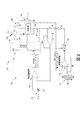
図1は、典型的な高電圧電流源を概略的に示す図である。図1において、整流102を有するフライバック変換器118はDC高電圧を生成するために使用される。図1において、I0は出力電流106であり、負荷116に供給される。リークがない(Ileak=0)場合、誤差増幅器108の反転入力における電圧はI0.RSである。出力電流106は(電圧源110により)VSETによって設定され、I0=VSET/RSとなる。リーク112がある場合、誤差増幅器108の反転入力における電圧(I0+Ileak).RSであり、よって、出力電流106Io=VSETRS−Ileakとなる。言い換えれば、出力電流106は、リーク電流112が(アイテム114によって示されるように)出力電流の成分であると考えられるので、Ileakが予想より低いことから、この回路は幾分有効であるが、誤差増幅器108はリーク112を適切に補償するとはいえない。
FIG. 1 schematically illustrates a typical high voltage current source. In FIG. 1, a
本明細書中の図面において同一の識別番号は同一または同様の構成要素を指している。図2は、以上のような課題を解決するために、トランス抵抗増幅器122と、減算論理素子124と、分圧器126と、を有する湿度センサ120を含む。図中、Rhは湿度センサ120の抵抗を表し、リーク112は抵抗器Rleakでモデル化され得る。
In the drawings in this specification, the same identification numbers indicate the same or similar components. FIG. 2 includes a
図2に示したシステムにおいて、電流Ileak112を補償し、誤差増幅器108の反転入力が、あたかもリークがなかったかの如く、I0.RSを受信することを可能にする。
トランス抵抗増幅器122の出力は、
![]()
![]()
よって、補償電流IRCは、等式

これは、Ileak112に等しい。
![]()
The output of the
![]()
![]()
Thus, the compensation current IR C is, equation
This is equal to
![]()
以上の等式は、湿度センサ120(IRh)を流れる電流がリーク電流112に比例していることを示している。これはすべての湿度レベルだけでなくすべての出力電圧レベル(VO)にも有効である。より具体的には、リーク電流112は、分圧器126によって感知される電流源210からの出力電圧VOに依存するが、トランス抵抗増幅器122を介して分圧器126からVM=VO.βの送信によるIRhにも同様の依存傾向が必要とされる。より具体的には、分圧器126は以下の等式に使用される:
![]()
![]()
![]()
V0は省略できる:
![]()
![]()
![]()
![]()
![]()
V0 can be omitted:
![]()
![]()
当業者は、様々な抵抗素子(Rf、Rc、βなど)が必要に応じて各個別の特定状況ごとに正確なスケーリングを実行するように調整かつカスタマイズされ得ることを理解するであろう。更に、当業者は、図1および2が単に二つの具体例にすぎず、以下に提示される特許請求の範囲が、図3〜5に示したより汎用化された構造などの(アナログおよびディジタルの両面で)より汎用化された構造に適用可能であることを理解するであろう。よって、図2は必要とされる動作の単なる表示にすぎない。本発明が、アナログおよびディジタルの両面でより多くのインプリメンテーションの可能性があることが理解されよう。 Those skilled in the art will appreciate that the various resistive elements (Rf, Rc, β, etc.) can be adjusted and customized to perform accurate scaling for each individual specific situation as needed. Further, those skilled in the art will appreciate that FIGS. 1 and 2 are merely two examples, and that the claims presented below are more generalized structures such as those shown in FIGS. 3-5 (analog and digital). It will be understood that it is applicable to more generalized structures (both sides). Thus, FIG. 2 is merely a display of the required operations. It will be appreciated that the present invention has more implementation possibilities in both analog and digital.
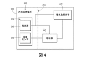
図3に示したように、本明細書の例示的な装置(その一つをアイテム200として示す)は、少なくとも一つの内部湿潤場所202(例えば、装置200の外部エリアの湿度レベルより高い湿度レベルを受ける内部の場所202)を有している。相対的に高い湿度エリア202は、装置200の内部全体(ライン204で示す)より小さいかまたは装置200の内部全体が相対的に高い湿度を受ける可能性がある。
As shown in FIG. 3, the exemplary device herein (one of which is shown as item 200) has a humidity level that is higher than at least one internal wet location 202 (eg, a humidity level in an external area of device 200). Internal location 202). The relatively
装置200は同装置200の内部湿潤場所202内で少なくとも一つの電流源210を利用する。また、電気負荷素子220は電流源210に接続されている。電流源210は電気負荷素子220へ一次出力電流(例えば、直流(DC))を提供する。電流源210は、湿潤場所202の湿度レベルが高くなるにつれて増加した不要なリーク電流を受け、このような湿度の上昇に起因してリーク電流が増加した分だけ電気負荷素子220へ送出される一次出力電流を低下させる。
The
このような課題を解決するために、本発明による装置200は、電流源210に接続された分圧器222と、装置200の内部湿潤場所202内の湿度センサ212と、該分圧器222と該湿度センサ212に接続された増幅器224と、を含む。湿度センサ212は湿度レベルが上昇するにつれて高くなった電流信号を生成し、増幅器224は湿度センサ212によって生成された信号を増幅して、補償出力電流を生成する。増幅器224は、一次出力電流が上昇するにつれて高くなったレベルで湿度センサ212が生成した信号の増幅を提供する(図3に示したように、一次出力電流は分圧器222によって増幅器224へ送出される)。よって、増幅器224は、補償出力電流をリーク電流と同等にするレベルで湿度センサ212が生成した信号を増幅させる。
In order to solve such a problem, the
また、増幅器224は、一次出力電流を有する電気負荷素子220へ補償出力電流を送出する。これにより電気負荷素子220がリーク電流の影響を受けない(リーク電流によって低下しない)電源電流としての補償出力電流と組み合わされた一次出力電流を受けることが可能になる。
In addition, the
また、電流源210と湿度センサ212は、同一のプリント回路基板214上に配置され、装置200の湿潤場所202内の被湿潤度および湿度に対してほぼ同様に反応するほぼ同じ大きさを有し互いに間隔をとって配設されている素子(例えば、ほぼ同じ大きさの導体および絶縁体)を有することができる。ここでも、被湿潤度および湿度はリーク電流の多くを生じる役割を果たす。電流源210と湿度センサ212がほぼ同様の大きさの導体および絶縁体を有することで、湿度センサ212からの増幅信号を電流源210が受けるリーク電流に一致させることを可能とし、よって、一次出力電流を補う極めて有効な補償出力電流として機能し、電気負荷素子220がリーク電流に影響されない電力電流を受けることができる。
Also, the
一例において、湿度センサ212は、対向端子、これらの端子に接続されたインターリーブ導体、インターリーブ導体(例えば、図2に示したアイテム120において示されたインターリーブ導体)間に発生する電気絶縁性を含むことができる。しかしながら、当業者は、任意の湿度センサ(または湿度および被湿潤度によって影響される導電性を有する素子/回路)は要素212として使用されてよいことを理解するであろう。図4および5は、分圧器222を設けていないこと以外は図3と同様の構造を示している。図4の構造もまた、増幅器224へ出力電流を供給し、増幅器224は一次出力電流が増加するにつれて出力電流を補償する際に増加を提供することを可能にする。図5の構造は、一次出力電流の増加に伴って出力電流を補償する際に増加を提供しないが、図5の構造は、リーク電流を補償することを補助する。また、図5に示した構造は、低コストで、小型であるが、ある状況に対して十分に対応できる構造である。図4の構造も、増幅器が一次出力電流の増加を補償することを可能にする。よって、図4の構造において、性能低下がなく、低コストで、(図からもわかるように)小型構造である。
In one example,
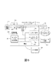
図6は、印刷装置304であるコンピュータ装置を示しており、印刷装置304は、本発明のシステムおよび方法と共に使用され、例えば、プリンタ、複写機、複合機、多機能装置(MFD)などを含み得る。印刷装置304は、プロセッサ324と、コンピュータ装置300の外部のコンピュータネットワーク302と、に動作可能に連結されたコントローラ/プロセッサ324および通信ポート(入力/出力)326を含む。更に、印刷装置304は、(電源322を介して)外部電源328からの供給電源上で動作するグラフィックユーザインターフェースアセンブリ336などの少なくとも一つのアクセサリ機能コンポーネントを含むことができる。
FIG. 6 shows a computer device, which is a
入出力装置326はコンピュータ装置300に対して通信をやり取りするために使用される。プロセッサ324はコンピュータ装置の様々なアクションをコントロールする。(光、磁気、コンデンサベースなどの)非一時的なコンピュータ記憶媒体装置330はプロセッサ324によって読み出し可能であり、プロセッサ324が本明細書に記載したような様々な機能をコンピュータ装置に実行させるように実施する指令を格納する。よって、図6に示したように、筐体は電源322によって交流(AC)電源328から供給された電力で動作する一以上の機能的コンポーネントを有している。電源322は蓄電素子(例えば、バッテリなど)を含むことができる。
The input /
印刷装置304は、プロセッサ324に動作可能に接続された各々が上記に例示し説明した構造(図2〜5参照)を含む少なくとも一つのマーキング装置(プリントエンジン)310、給紙装置314からこのマーキング装置(複数可)310へ媒体シートを供給するように位置決めされた媒体経路316などを含む。プリントエンジン(複数可)から様々なマーキングを受けとった後、媒体シートは、必要に応じて、様々な印刷済みシートを折り畳み、ホチキス止め、仕分けなどを行うことができるフィニッシャ308へパスされる。また、印刷装置304は、(電源322を介して)外部電源328からの供給電源上で動作する(スキャナ/ドキュメントハンドラ312などの)少なくとも一つのアクセサリ機能コンポーネントを含むこともできる。
The
図3〜6に概略的に示したすべての要素は、現在知られているか、または今後開発され得るかにかかわらず、上述の機能と同じ機能を実行するすべての周知のデバイスを網羅することを意図している。よって、本明細書に例示したものは、本明細書の構造をより明確に理解してもらうために利用されているにすぎず、以下の特許請求の範囲を限定するものではない。 All elements shown schematically in FIGS. 3-6 are intended to cover all known devices that perform the same functions as described above, whether currently known or may be developed in the future. Intended. Therefore, what was illustrated in this specification is only used in order that a structure of this specification may be understood more clearly, and does not limit the following claims.
数多くのコンピュータ装置が上述されている。チップベースの中央処理装置(CPU)、グラフィックユーザインターフェース(GUI)を含む入力/出力デバイス、メモリ、比較器、プロセッサなどを含むコンピュータ装置は良く知られており、Dellコンピュータ社(米国、テキサス州、ラウンドロック)、アップルコンピュータ社(米国、カリフォルニア州、クパチーノ)などの製造者から容易に入手できる。このようなコンピュータ装置は、入力/出力装置、電源、プロセッサ、電子記憶メモリ、配線などを一般に含むが、読者の皆様には、本明細書に記載されているシステムおよび方法の顕著な側面をより良好に理解していただきたいので、ここでは詳述しない。同様に、スキャナおよび他の同様の周辺機器は、ゼロックス社(米国、コネティカット、ノーウォーク)から入手できるが、説明をより明確にし、本発明をより良好に理解していただきたいので、ここでは、詳述しない。 A number of computer devices have been described above. Computer devices including chip-based central processing units (CPUs), input / output devices including graphic user interfaces (GUIs), memories, comparators, processors, etc. are well known, Dell Computer Corporation (Texas, USA, Round Rock), Apple Computer Inc. (Cupuccino, California, USA) and other manufacturers. Such computing devices typically include input / output devices, power supplies, processors, electronic storage memory, wiring, etc., but readers will appreciate the significant aspects of the systems and methods described herein. It will not be described in detail here as it is better understood. Similarly, scanners and other similar peripherals are available from Xerox Corporation (USA, Connecticut, Norwalk), but for clarity of explanation and a better understanding of the present invention, Not detailed.
本明細書中で使用されている用語「プリンタ」または「印刷装置」は、ディジタル複写機、製本機、ファクシミリ装置、複合機などの任意の装置を包含し、任意の目的のために印刷出力機能を実行する。プリンタ、印刷エンジンなどの詳細は周知であり、本開示が提示する特徴に注目してもらうために本明細書では詳細な説明はしない。本発明によるシステムおよび方法は、本明細書にカラー、モノクロでプリントするか、または、カラーまたはモノクロの画像データを取り扱うシステムおよび方法を包含することができる。すべての前述のシステムおよび方法は、具体的に、静電グラフィックおよび/またはゼログラフィックマシンおよび/またはプロセスに適用可能である。 As used herein, the term “printer” or “printing device” includes any device such as a digital copying machine, a bookbinding machine, a facsimile machine, and a multifunction machine, and has a print output function for any purpose. Execute. Details of printers, print engines, etc. are well known, and will not be described in detail herein in order to draw attention to the features presented by the present disclosure. Systems and methods according to the present invention can include systems and methods that print in color, monochrome, or handle color or monochrome image data herein. All the aforementioned systems and methods are specifically applicable to electrostatic graphics and / or xerographic machines and / or processes.
更に、「接触(touching、)」、「上に(on)」、「直接接触している(in direct contact)」、「当接している(abutting)」、「直接隣り合っている(directly adjacent to)」などの用語は、少なくとも一つの要素が(他の要素が上記の要素を分離させずに)他の要素に物理的に接触することを意味する。また、自動化(automated)または「自動的に(automatically)」の用語は、(マシンまたはユーザによって)プロセスがスタートすると、一以上のマシンがユーザからの更なる入力がなくてもプロセスを実行することを意味する。 In addition, “touching”, “on”, “in direct contact”, “acting”, “directly adjacent” to) "means that at least one element is in physical contact with another element (without the other element separating the above elements). Also, the term “automated” or “automatically” means that when a process is started (by a machine or a user), one or more machines execute the process without further input from the user. Means.
望ましくは、上記に開示した、他の、または代替的な特徴および機能を多くの他の異なるシステムまたはアプリケーションに組み合わせてもよいことが理解されよう。以下の特許請求の範囲に意図して包合される、現在は予見または予期できないが、今後、当業者によって様々な代替、修正、変形、または改良が行われる可能性がある。ある特定のクレーム自体に具体的に定義されていなければ、本発明のシステムおよび方法のステップまたは構成要素は、任意の特定の順序、数、位置、大きさ、形状、角度、色、または材料を制約するものとして、上記の実施例から示唆または取り込むことはできない。 It will be appreciated that other or alternative features and functions disclosed above may be combined into many other different systems or applications, as desired. Various alternatives, modifications, variations, or improvements may be made by those skilled in the art in the future, which are now foreseen or unexpected, and are intended to be encompassed by the following claims. Unless specifically defined in certain claims themselves, the steps or components of the systems and methods of the present invention may be in any particular order, number, location, size, shape, angle, color, or material. As a limitation, it cannot be suggested or taken from the above examples.
Claims (20)
前記装置の外部エリアの湿度レベルより高い湿度レベルを有している内部湿潤場所と、
前記装置の前記内部湿潤場所内の電流源であって、前記湿度レベルが上昇するにつれて高くなるリーク電流を受流する電流源と、
前記装置の前記内部湿潤場所内に設けられた湿度センサであって、前記湿度レベルが上昇するにつれて高くなる信号を生成する湿度センサと、
前記電流源と前記湿度センサに連結された増幅器と、
前記電流源と前記増幅器に連結された電気負荷素子と、
を含み、
前記電流源が前記電気負荷素子へ一次出力電流を送出し、
前記一次出力電流の低下に対応して前記リーク電流を増加させ、
前記増幅器が、補償出力電流を生成するために前記湿度センサによって生成された前記信号を増幅させ、
前記増幅器が、前記補償出力電流を前記リーク電流に等しくさせるレベルにおいて前記湿度センサによって生成された前記信号を増幅させ、
前記増幅器が、前記一次出力電流を有する前記電気負荷素子へ前記補償出力電流を送出する、
装置。 A device,
An internal wet location having a humidity level higher than the humidity level of the external area of the device;
A current source in the internal wet location of the apparatus for receiving a leakage current that increases as the humidity level increases;
A humidity sensor provided in the internal wet location of the device, wherein the humidity sensor generates a signal that increases as the humidity level increases;
An amplifier coupled to the current source and the humidity sensor;
An electrical load element coupled to the current source and the amplifier;
Including
The current source delivers a primary output current to the electrical load element;
Increasing the leakage current in response to a decrease in the primary output current,
The amplifier amplifies the signal generated by the humidity sensor to generate a compensated output current;
The amplifier amplifies the signal generated by the humidity sensor at a level that makes the compensated output current equal to the leakage current;
The amplifier delivers the compensated output current to the electrical load element having the primary output current;
apparatus.
対向端子と、
前記対向端子に接続されたインターリーブ導体と、
前記インターリーブ導体間に設けられた電気絶縁体と、
を含む請求項1に記載の装置。 The humidity sensor is
Opposite terminal,
An interleaved conductor connected to the opposing terminal;
An electrical insulator provided between the interleaved conductors;
The apparatus of claim 1 comprising:
前記一次出力電流が増加するにつれて増加するリーク電流を受流する請求項1に記載の装置。 The current source is
The apparatus of claim 1, wherein the apparatus receives a leakage current that increases as the primary output current increases.
プリントエンジンと、
前記プリントエンジン内に設けられ、前記プリントエンジンの外部エリアの湿度レベルより高い湿度レベルを有している内部湿潤場所と、
前記装置の前記内部湿潤場所内の電流源であって、前記湿度レベルが上昇するにつれて高くなるリーク電流を受流する電流源と、
前記電流源に連結された分圧器と、
前記装置の前記内部湿潤場所内に設けられた湿度センサであって、前記湿度レベルが上昇するにつれて高くなる信号を生成する湿度センサと、
前記分圧器と前記湿度センサに連結された増幅器と、
前記電流源と前記増幅器に連結された電気負荷素子と、
を含み、
前記電流源が前記電気負荷素子へ一次出力電流を送出し、
前記一次出力電流の低下に対応して前記リーク電流を増加させ、
前記増幅器が、補償出力電流を生成するために前記湿度センサによって生成された前記信号を増幅させ、
前記増幅器が、前記分圧器によって前記増幅器に提供された前記一次出力電流が上昇するにつれて高くなるレベルで前記湿度センサによって生成された前記信号を増幅させ、
前記増幅器が、前記補償出力電流を前記リーク電流に等しくさせる前記レベルにおいて前記湿度センサによって生成された前記信号を増幅させ、
前記増幅器が、前記一次出力電流を有する前記電気負荷素子へ前記補償出力電流を送出する、
装置。 A device,
A print engine,
An internal wet location provided within the print engine and having a humidity level higher than a humidity level of an external area of the print engine;
A current source in the internal wet location of the apparatus for receiving a leakage current that increases as the humidity level increases;
A voltage divider coupled to the current source;
A humidity sensor provided in the internal wet location of the device, wherein the humidity sensor generates a signal that increases as the humidity level increases;
An amplifier coupled to the voltage divider and the humidity sensor;
An electrical load element coupled to the current source and the amplifier;
Including
The current source delivers a primary output current to the electrical load element;
Increasing the leakage current in response to a decrease in the primary output current,
The amplifier amplifies the signal generated by the humidity sensor to generate a compensated output current;
The amplifier amplifies the signal generated by the humidity sensor at a level that increases as the primary output current provided to the amplifier by the voltage divider increases;
The amplifier amplifies the signal generated by the humidity sensor at the level that causes the compensated output current to be equal to the leakage current;
The amplifier delivers the compensated output current to the electrical load element having the primary output current;
apparatus.
対向端子と、
前記対向端子に接続されたインターリーブ導体と、
前記インターリーブ導体間に設けられた電気絶縁体と、
を含む請求項8に記載の装置。 The humidity sensor is
Opposite terminal,
An interleaved conductor connected to the opposing terminal;
An electrical insulator provided between the interleaved conductors;
The apparatus of claim 8 comprising:
前記一次出力電流が増加するにつれて増加するリーク電流を受流する請求項8に記載の装置。 The current source is
9. The apparatus of claim 8, wherein the apparatus receives a leakage current that increases as the primary output current increases.
プリントエンジンと、
前記プリントエンジン内に設けられ、前記プリントエンジンの外部エリアの湿度レベルより高い湿度レベルを有している内部湿潤場所と、
前記装置の前記内部湿潤場所内の電流源であって、前記湿度レベルが上昇するにつれて高くなるリーク電流を受流する電流源と、
前記電流源に連結された分圧器と、
前記装置の前記内部湿潤場所内に設けられた湿度センサであって、前記湿度レベルが上昇するにつれて高くなる信号を生成する湿度センサと、
前記分圧器と前記湿度センサに連結された増幅器と、
前記電流源と前記増幅器に連結された電気負荷素子と、
を含み、
前記電流源が前記電気負荷素子へ一次出力電流を送出し、
前記リーク電流の増加分だけ前記一次出力電流を低下させ、
前記増幅器が、補償出力電流を生成するために前記湿度センサによって生成された前記信号を増幅させ、
前記増幅器が、前記分圧器によって前記増幅器に提供された前記一次出力電流が上昇するにつれて高くなるレベルで前記湿度センサによって生成された前記信号を増幅させ、
前記増幅器が、前記補償出力電流を前記リーク電流に等しくさせる前記レベルにおいて前記湿度センサによって生成された前記信号を増幅させ、
前記増幅器が、前記一次出力電流を有する前記電気負荷素子へ前記補償出力電流を送出する、
装置。 A device,
A print engine,
An internal wet location provided within the print engine and having a humidity level higher than a humidity level of an external area of the print engine;
A current source in the internal wet location of the apparatus for receiving a leakage current that increases as the humidity level increases;
A voltage divider coupled to the current source;
A humidity sensor provided in the internal wet location of the device, wherein the humidity sensor generates a signal that increases as the humidity level increases;
An amplifier coupled to the voltage divider and the humidity sensor;
An electrical load element coupled to the current source and the amplifier;
Including
The current source delivers a primary output current to the electrical load element;
Reducing the primary output current by an increase in the leakage current;
The amplifier amplifies the signal generated by the humidity sensor to generate a compensated output current;
The amplifier amplifies the signal generated by the humidity sensor at a level that increases as the primary output current provided to the amplifier by the voltage divider increases;
The amplifier amplifies the signal generated by the humidity sensor at the level that causes the compensated output current to be equal to the leakage current;
The amplifier delivers the compensated output current to the electrical load element having the primary output current;
apparatus.
対向端子と、
前記対向端子に接続されたインターリーブ導体と、
前記インターリーブ導体間に設けられた電気絶縁体と、
を含む請求項15に記載の装置。 The humidity sensor is
Opposite terminal,
An interleaved conductor connected to the opposing terminal;
An electrical insulator provided between the interleaved conductors;
The apparatus of claim 15 comprising:
16. The current source and the humidity sensor have conductors and insulators of approximately the same size that are substantially similar to wetness and humidity and spaced from each other. The device described.
Applications Claiming Priority (2)
| Application Number | Priority Date | Filing Date | Title |
|---|---|---|---|
| US14/093,582 US9164477B2 (en) | 2013-12-02 | 2013-12-02 | Current leakage correction in humid environments |
| US14/093,582 | 2013-12-02 |
Publications (3)
| Publication Number | Publication Date |
|---|---|
| JP2015106158A JP2015106158A (en) | 2015-06-08 |
| JP2015106158A5 JP2015106158A5 (en) | 2017-12-28 |
| JP6268076B2 true JP6268076B2 (en) | 2018-01-24 |
Family
ID=53265249
Family Applications (1)
| Application Number | Title | Priority Date | Filing Date |
|---|---|---|---|
| JP2014234194A Active JP6268076B2 (en) | 2013-12-02 | 2014-11-19 | Leakage current correction in humid environment |
Country Status (2)
| Country | Link |
|---|---|
| US (1) | US9164477B2 (en) |
| JP (1) | JP6268076B2 (en) |
Families Citing this family (2)
| Publication number | Priority date | Publication date | Assignee | Title |
|---|---|---|---|---|
| DE102018126608A1 (en) * | 2018-10-25 | 2020-04-30 | Sensus Spectrum Llc | Measuring device for determining a measured value in humid ambient conditions |
| CN111880111A (en) * | 2020-06-23 | 2020-11-03 | 南方电网科学研究院有限责任公司 | Leakage current measuring device, system and method for high-voltage direct current cable |
Family Cites Families (14)
| Publication number | Priority date | Publication date | Assignee | Title |
|---|---|---|---|---|
| JPH01291274A (en) * | 1988-05-18 | 1989-11-22 | Oki Electric Ind Co Ltd | Developing device for electrophotographic device |
| KR960007569Y1 (en) | 1990-06-30 | 1996-08-30 | 엘지전자 주식회사 | Fan motor rotating number regulating circuit in microwave oven |
| JP3258180B2 (en) * | 1994-10-19 | 2002-02-18 | シャープ株式会社 | Charging device design method |
| CN1099590C (en) | 1994-12-29 | 2003-01-22 | Nec东金株式会社 | Humidity sensor |
| US5757195A (en) | 1996-07-19 | 1998-05-26 | Honeywell Inc. | Humidity sensing circuit |
| JP3426895B2 (en) * | 1997-01-30 | 2003-07-14 | シャープ株式会社 | Image quality compensation device for image forming apparatus |
| US6079121A (en) * | 1998-08-03 | 2000-06-27 | Ther-O-Disc, Incorporated | Humidity-modulated dual-setpoint temperature controller |
| JP3440457B2 (en) | 1998-12-14 | 2003-08-25 | 松下電器産業株式会社 | Humidity detecting device and method |
| KR100351810B1 (en) * | 1999-12-13 | 2002-09-11 | 엘지전자 주식회사 | absolute humidity sensor |
| DE10052532C2 (en) | 2000-10-23 | 2002-11-14 | Conducta Endress & Hauser | Printed circuit board with an input circuit for receiving and processing an electrical signal and using the printed circuit board |
| AU2001244821A1 (en) | 2000-11-21 | 2002-06-03 | Lg Electronics Inc. | Bolometric humidity sensor and cooker using the same and method for controlling the cooker |
| JP2003122107A (en) * | 2001-10-17 | 2003-04-25 | Canon Inc | Developing device |
| KR100598403B1 (en) | 2004-11-17 | 2006-07-07 | 삼성전자주식회사 | Microwave heating apparatus and control method thereof |
| US7999416B2 (en) | 2008-04-14 | 2011-08-16 | Emergie H. T. International Inc. | Module for controlling a switch in a high voltage electrical substation |
-
2013
- 2013-12-02 US US14/093,582 patent/US9164477B2/en not_active Expired - Fee Related
-
2014
- 2014-11-19 JP JP2014234194A patent/JP6268076B2/en active Active
Also Published As
| Publication number | Publication date |
|---|---|
| US9164477B2 (en) | 2015-10-20 |
| US20150153709A1 (en) | 2015-06-04 |
| JP2015106158A (en) | 2015-06-08 |
Similar Documents
| Publication | Publication Date | Title |
|---|---|---|
| US10842019B2 (en) | Printed circuit board and image forming apparatus | |
| KR101743518B1 (en) | Image forming apparatus and circuit board in image forming apparatus | |
| US7391334B2 (en) | Connection checking system, printer device, method of checking connected state, connection checking program, and recording medium storing connection checking program | |
| JP2008058481A (en) | Image forming apparatus and disconnection inspection method therefor | |
| JP6268076B2 (en) | Leakage current correction in humid environment | |
| JP7387828B2 (en) | Image forming device | |
| CN113954529B (en) | Consumable allowance display method, consumable chip, consumable and storage medium | |
| KR101238372B1 (en) | Apparatus for supplying high voltage power | |
| JP2005243575A (en) | Connection determining mechanism, printer, connection determining method, connection determining program, and recording medium recording connection determining program | |
| US20230209699A1 (en) | Humidity-adjusted power supply | |
| US8260167B2 (en) | High-voltage power supply | |
| US11061349B2 (en) | Heating device, fixing device and image forming apparatus | |
| JP4306369B2 (en) | Power supply device and image forming apparatus | |
| US10139778B2 (en) | Image forming apparatus and method of controlling transfer power thereof | |
| EP0448026A2 (en) | Power supply. | |
| JP2017227821A (en) | Image formation apparatus | |
| JP5826785B2 (en) | Image forming apparatus | |
| US20230116799A1 (en) | Capacitance based paper detection | |
| JP4421379B2 (en) | Remaining amount detection device | |
| JP4423923B2 (en) | Image forming apparatus | |
| JP4775467B2 (en) | High voltage power supply | |
| JP2023061607A (en) | Operation device and electronic apparatus | |
| JPH1067441A (en) | Paper feeder | |
| JP2021026931A (en) | Rotary switch switching position detection circuit, and image forming apparatus including the same | |
| JP2006091286A (en) | Image forming device |
Legal Events
| Date | Code | Title | Description |
|---|---|---|---|
| A521 | Request for written amendment filed |
Free format text: JAPANESE INTERMEDIATE CODE: A523 Effective date: 20171115 |
|
| A621 | Written request for application examination |
Free format text: JAPANESE INTERMEDIATE CODE: A621 Effective date: 20171115 |
|
| A871 | Explanation of circumstances concerning accelerated examination |
Free format text: JAPANESE INTERMEDIATE CODE: A871 Effective date: 20171115 |
|
| A975 | Report on accelerated examination |
Free format text: JAPANESE INTERMEDIATE CODE: A971005 Effective date: 20171213 |
|
| TRDD | Decision of grant or rejection written | ||
| A01 | Written decision to grant a patent or to grant a registration (utility model) |
Free format text: JAPANESE INTERMEDIATE CODE: A01 Effective date: 20171219 |
|
| R150 | Certificate of patent or registration of utility model |
Ref document number: 6268076 Country of ref document: JP Free format text: JAPANESE INTERMEDIATE CODE: R150 |
|
| R250 | Receipt of annual fees |
Free format text: JAPANESE INTERMEDIATE CODE: R250 |
|
| R250 | Receipt of annual fees |
Free format text: JAPANESE INTERMEDIATE CODE: R250 |
|
| R250 | Receipt of annual fees |
Free format text: JAPANESE INTERMEDIATE CODE: R250 |