JP6267700B2 - 3D scanning and positioning interface - Google Patents
3D scanning and positioning interface Download PDFInfo
- Publication number
- JP6267700B2 JP6267700B2 JP2015522189A JP2015522189A JP6267700B2 JP 6267700 B2 JP6267700 B2 JP 6267700B2 JP 2015522189 A JP2015522189 A JP 2015522189A JP 2015522189 A JP2015522189 A JP 2015522189A JP 6267700 B2 JP6267700 B2 JP 6267700B2
- Authority
- JP
- Japan
- Prior art keywords
- posture
- freedom
- estimated
- unreliable
- index
- Prior art date
- Legal status (The legal status is an assumption and is not a legal conclusion. Google has not performed a legal analysis and makes no representation as to the accuracy of the status listed.)
- Active
Links
- 230000000007 visual effect Effects 0.000 claims description 60
- 230000035945 sensitivity Effects 0.000 claims description 25
- 238000000034 method Methods 0.000 claims description 22
- 239000011159 matrix material Substances 0.000 claims description 18
- 230000001186 cumulative effect Effects 0.000 claims description 16
- 230000001960 triggered effect Effects 0.000 claims description 13
- 230000002123 temporal effect Effects 0.000 claims description 5
- 238000001514 detection method Methods 0.000 claims description 2
- 206010034719 Personality change Diseases 0.000 claims 1
- 239000013598 vector Substances 0.000 description 21
- 238000013519 translation Methods 0.000 description 17
- 230000014616 translation Effects 0.000 description 17
- 238000013459 approach Methods 0.000 description 7
- 230000005484 gravity Effects 0.000 description 5
- 230000006870 function Effects 0.000 description 4
- 238000012360 testing method Methods 0.000 description 4
- 230000008859 change Effects 0.000 description 3
- 238000012546 transfer Methods 0.000 description 3
- 230000009466 transformation Effects 0.000 description 3
- 238000009825 accumulation Methods 0.000 description 2
- 238000006243 chemical reaction Methods 0.000 description 2
- 230000003247 decreasing effect Effects 0.000 description 2
- 238000010586 diagram Methods 0.000 description 2
- 238000006073 displacement reaction Methods 0.000 description 2
- 230000008569 process Effects 0.000 description 2
- 230000008901 benefit Effects 0.000 description 1
- 239000003086 colorant Substances 0.000 description 1
- 238000011109 contamination Methods 0.000 description 1
- 230000007423 decrease Effects 0.000 description 1
- 239000004744 fabric Substances 0.000 description 1
- 238000001914 filtration Methods 0.000 description 1
- 238000005286 illumination Methods 0.000 description 1
- 238000003384 imaging method Methods 0.000 description 1
- 238000010606 normalization Methods 0.000 description 1
- 230000003287 optical effect Effects 0.000 description 1
- 230000002265 prevention Effects 0.000 description 1
- 238000012545 processing Methods 0.000 description 1
- 238000005070 sampling Methods 0.000 description 1
- 230000011218 segmentation Effects 0.000 description 1
Images


Classifications
-
- G—PHYSICS
- G01—MEASURING; TESTING
- G01B—MEASURING LENGTH, THICKNESS OR SIMILAR LINEAR DIMENSIONS; MEASURING ANGLES; MEASURING AREAS; MEASURING IRREGULARITIES OF SURFACES OR CONTOURS
- G01B21/00—Measuring arrangements or details thereof, where the measuring technique is not covered by the other groups of this subclass, unspecified or not relevant
- G01B21/20—Measuring arrangements or details thereof, where the measuring technique is not covered by the other groups of this subclass, unspecified or not relevant for measuring contours or curvatures, e.g. determining profile
-
- G—PHYSICS
- G01—MEASURING; TESTING
- G01B—MEASURING LENGTH, THICKNESS OR SIMILAR LINEAR DIMENSIONS; MEASURING ANGLES; MEASURING AREAS; MEASURING IRREGULARITIES OF SURFACES OR CONTOURS
- G01B11/00—Measuring arrangements characterised by the use of optical techniques
- G01B11/002—Measuring arrangements characterised by the use of optical techniques for measuring two or more coordinates
-
- G—PHYSICS
- G01—MEASURING; TESTING
- G01B—MEASURING LENGTH, THICKNESS OR SIMILAR LINEAR DIMENSIONS; MEASURING ANGLES; MEASURING AREAS; MEASURING IRREGULARITIES OF SURFACES OR CONTOURS
- G01B11/00—Measuring arrangements characterised by the use of optical techniques
- G01B11/24—Measuring arrangements characterised by the use of optical techniques for measuring contours or curvatures
- G01B11/25—Measuring arrangements characterised by the use of optical techniques for measuring contours or curvatures by projecting a pattern, e.g. one or more lines, moiré fringes on the object
-
- G—PHYSICS
- G06—COMPUTING; CALCULATING OR COUNTING
- G06T—IMAGE DATA PROCESSING OR GENERATION, IN GENERAL
- G06T7/00—Image analysis
- G06T7/50—Depth or shape recovery
- G06T7/521—Depth or shape recovery from laser ranging, e.g. using interferometry; from the projection of structured light
-
- G—PHYSICS
- G06—COMPUTING; CALCULATING OR COUNTING
- G06T—IMAGE DATA PROCESSING OR GENERATION, IN GENERAL
- G06T7/00—Image analysis
- G06T7/70—Determining position or orientation of objects or cameras
- G06T7/73—Determining position or orientation of objects or cameras using feature-based methods
-
- G—PHYSICS
- G01—MEASURING; TESTING
- G01B—MEASURING LENGTH, THICKNESS OR SIMILAR LINEAR DIMENSIONS; MEASURING ANGLES; MEASURING AREAS; MEASURING IRREGULARITIES OF SURFACES OR CONTOURS
- G01B2210/00—Aspects not specifically covered by any group under G01B, e.g. of wheel alignment, caliper-like sensors
- G01B2210/52—Combining or merging partially overlapping images to an overall image
-
- G—PHYSICS
- G06—COMPUTING; CALCULATING OR COUNTING
- G06T—IMAGE DATA PROCESSING OR GENERATION, IN GENERAL
- G06T2200/00—Indexing scheme for image data processing or generation, in general
- G06T2200/04—Indexing scheme for image data processing or generation, in general involving 3D image data
-
- G—PHYSICS
- G06—COMPUTING; CALCULATING OR COUNTING
- G06T—IMAGE DATA PROCESSING OR GENERATION, IN GENERAL
- G06T2207/00—Indexing scheme for image analysis or image enhancement
- G06T2207/10—Image acquisition modality
- G06T2207/10028—Range image; Depth image; 3D point clouds
Landscapes
- Physics & Mathematics (AREA)
- Engineering & Computer Science (AREA)
- General Physics & Mathematics (AREA)
- Computer Vision & Pattern Recognition (AREA)
- Theoretical Computer Science (AREA)
- Optics & Photonics (AREA)
- Length Measuring Devices With Unspecified Measuring Means (AREA)
- Image Analysis (AREA)
- Length Measuring Devices By Optical Means (AREA)
- Processing Or Creating Images (AREA)
Description
本発明は、物体の表面形状の3次元走査の分野に主に関し、より詳細には、立体照明立体視法に関する。 The present invention relates mainly to the field of three-dimensional scanning of the surface shape of an object, and more particularly to stereoscopic illumination stereoscopic viewing.
物体の表面形状の3次元走査およびデジタル化は、多くの業界およびサービスにおいて一般的に用いられており、その用途は極めて多い。物体の形状は、センサとその物体の表面上の1組の点との間の距離を測定する測距センサを用いて、走査されデジタル化される。センサは、物体の表面の断面を所与の視点から取得する。走査断面の伸張または表面全体の走査を行うために、センサまたは物体をいくつかの視点のうちの1つへ移動させ、センサと物体との間の全ての相対的姿勢間の空間関係を取得する。 Three-dimensional scanning and digitization of object surface shapes are commonly used in many industries and services, and their applications are numerous. The shape of the object is scanned and digitized using a ranging sensor that measures the distance between the sensor and a set of points on the surface of the object. The sensor obtains a cross-section of the surface of the object from a given viewpoint. To stretch the scan section or scan the entire surface, move the sensor or object to one of several viewpoints to obtain the spatial relationship between all relative poses between the sensor and the object. .
これらの空間関係の測定および計算については、いくつかのアプローチが存在する。これらのアプローチのうち1つにおいては、観測物体の形状を利用して、空間における、相対的なセンサの位置および向き、すなわち、その姿勢を計算する。これらの形状ベースのアプローチの場合、その場面で、標的または追加の基準を添付する必要が無いため、その取得の設定のための時間が短くてすむ。姿勢推定を信頼性良く確実に行うには、観測された形状断面の形状の複雑度が不十分である場合がある。平面状、球状、円筒状表面などの状態においては、センサー姿勢の6つの自由度を一義的に決定することが不可能であることが周知である。ノイズが存在する場合、非理想的な状態に起因して、信頼性の欠如した姿勢推定が発生し得る。 There are several approaches for measuring and calculating these spatial relationships. In one of these approaches, the shape of the observed object is used to calculate the relative sensor position and orientation in space, that is, its orientation. For these shape-based approaches, there is no need to attach a target or additional criteria in the scene, so the time for setting up the acquisition is reduced. In order to perform posture estimation reliably and reliably, the shape complexity of the observed shape cross section may be insufficient. It is well known that it is impossible to uniquely determine the six degrees of freedom of the sensor posture in a state such as a flat surface, a spherical surface, or a cylindrical surface. In the presence of noise, unreliable pose estimation can occur due to non-ideal conditions.
本発明の1つの広い側面によれば、位置決めの非信頼性についての指標を提供するシステムが提供される。このシステムは、物体の表面形状を走査し、当該スキャナのための形状ベースの位置決めを用いて複数のフレームの各フレームについて1組の3D点を累積するスキャナと、上記スキャナのために、上記3D点を用いて推定姿勢を推定する姿勢推定器と、上記推定姿勢が拘束されない位置決めを有するかを決定することを行う姿勢推定器と、上記推定姿勢が拘束されない位置決めを有するかどうかを決定し、上記推定された姿勢が拘束されない位置決めを有する場合には、上記推定姿勢を信頼性の欠如した姿勢推定として特定する非信頼性姿勢検出器と、上記信頼性の欠如した姿勢推定が検出された旨の指標を生成する指標生成器とを有する。 According to one broad aspect of the invention, a system is provided that provides an indication of positioning unreliability. The system scans the surface shape of the object and accumulates a set of 3D points for each frame of the plurality of frames using shape-based positioning for the scanner, and for the scanner the 3D A posture estimator that estimates an estimated posture using points, a posture estimator that determines whether the estimated posture has unconstrained positioning, and determines whether the estimated posture has unconstrained positioning, If the estimated posture has unconstrained positioning, an unreliable posture detector that identifies the estimated posture as an unreliable posture estimate, and that the unreliable posture estimate has been detected. And an index generator for generating the index.
一実施形態において、システムは、上記推定された姿勢において少なくとも1つ問題のある自由度を特定する自由度識別子をさらに有し、上記自由度識別子は、上記非信頼性姿勢検出器によってトリガされ、上記指標生成器によって生成された指標は、上記指標に少なくとも1つの問題のある自由度についての情報を含む。 In one embodiment, the system further comprises a degree of freedom identifier that identifies at least one problematic degree of freedom in the estimated posture, the degree of freedom identifier triggered by the unreliable posture detector, The index generated by the index generator includes information about at least one degree of freedom in which the index is problematic.
一実施形態において、指標生成器によって生成された指標は、問題のある自由度全てについての情報を含む。 In one embodiment, the index generated by the index generator includes information about all problematic degrees of freedom.
一実施形態において、システムは、上記複数のフレームのうち少なくとも2つにおいて上記スキャナにより再観察可能な特徴点の存在を検出する特徴点検出器をさらに有し、上記姿勢推定器は、上記3D点と共に上記特徴点を用いて上記推定姿勢を推定し、上記非信頼性姿勢検出器は、上記特徴点を用いて上記推定姿勢を信頼性の欠如した姿勢推定として特定する。 In one embodiment, the system further includes a feature point detector that detects the presence of a feature point that can be re-observed by the scanner in at least two of the plurality of frames, and the posture estimator includes the 3D point. In addition, the estimated posture is estimated using the feature point, and the unreliable posture detector specifies the estimated posture as the posture estimation lacking reliability using the feature point.
一実施形態において、システムは、スピーカをさらに有し、上記指標生成器は、上記スピーカに可聴指標を出させる。 In one embodiment, the system further comprises a speaker, and the indicator generator causes the speaker to emit an audible indicator.
一実施形態において、システムは、視覚インターフェースをさらに有し、上記指標生成器は、上記視覚インターフェースに視覚指標を表示させ、上記視覚指標は、テキストメッセージおよびグラフィカルメッセージのうち少なくとも1つである。 In one embodiment, the system further comprises a visual interface, wherein the indicator generator causes the visual interface to display a visual indicator, the visual indicator being at least one of a text message and a graphical message.
一実施形態において、システムは、モデルビルダをさらに有し、上記モデルビルダは、上記1組の3D点を用いて上記表面の形状の累積モデルを構築し、上記視覚インターフェースは、上記累積モデルのグラフィカル表示を表示し、上記視覚指標は、上記累積モデルの上記グラフィカル表示上に重ねられる。 In one embodiment, the system further comprises a model builder that builds a cumulative model of the surface shape using the set of 3D points, and the visual interface is a graphical representation of the cumulative model. A display is displayed and the visual indicator is overlaid on the graphical display of the cumulative model.
一実施形態において、システムは、上記1組の3D点によって変更された上記累積モデルの全ボクセルにおけるボクセル感度レベルの平均を累積するボクセル感度レベル計算器をさらに有し、上記視覚インターフェースは、上記ボクセル感度レベルに対応する色を用いて上記累積モデルの上記グラフィカル表示を表示する。 In one embodiment, the system further comprises a voxel sensitivity level calculator that accumulates an average of voxel sensitivity levels in all voxels of the cumulative model modified by the set of 3D points, the visual interface comprising the voxel The graphical representation of the cumulative model is displayed using a color corresponding to a sensitivity level.
一実施形態において、システムは、上記信頼性の欠如した姿勢の推定の信頼性欠如のレベルを決定し、上記信頼性欠如のレベルを所定の信頼性欠如の閾値と比較し、上記信頼性欠如のレベルが上記所定の信頼性欠如の閾値よりも低い場合にのみ、上記フレームのそれぞれの1組の3D点を上記モデルビルダーへ転送するフレーム選択器をさらに有する。 In one embodiment, the system determines a level of unreliability of the unreliable posture estimate, compares the level of unreliability to a predetermined unreliability threshold, and It further comprises a frame selector that transfers each set of 3D points of the frame to the model builder only if the level is below the predetermined unreliability threshold.
一実施形態において、上記視覚インターフェースは、上記走査の現在のフレームのグラフィカル表示を表示し、上記視覚指標は、上記現在のフレームの上記グラフィカル表示上に重ねられる。 In one embodiment, the visual interface displays a graphical representation of the current frame of the scan, and the visual indicator is overlaid on the graphical representation of the current frame.
一実施形態において、システムは、上記非信頼性姿勢検出器によってトリガされ、上記推定姿勢を用いて姿勢感度レベルを上記推定姿勢へ属性の付加をする姿勢感度レベル属性付加器をさらに含み、上記指標生成器によって生成された指標は、上記指標と共に、上記視覚指標の色である上記姿勢感度レベルについての情報を含む。 In one embodiment, the system further includes a posture sensitivity level attribute adder that is triggered by the unreliable posture detector and adds a posture sensitivity level to the estimated posture using the estimated posture. The index generated by the generator includes information on the posture sensitivity level that is the color of the visual index together with the index.
一実施形態において、システムは、上記推定姿勢に少なくとも1つの問題のある自由度を特定する自由度識別子をさらに有し、上記信頼性の欠如した自由度の識別子は、上記非信頼性姿勢検出器によってトリガされ、上記指標生成器によって生成された指標は、上記指標と共に、少なくとも1つの問題のある自由度についての情報を含み、上記グラフィカルメッセージは、上記問題のある自由度に対応する向きと共に表示される少なくとも1つの矢印を含む。 In one embodiment, the system further comprises a degree of freedom identifier that identifies at least one problematic degree of freedom in the estimated pose, wherein the unreliable degree of freedom identifier is the unreliable pose detector. The indicator triggered by and generated by the indicator generator includes information about at least one problematic degree of freedom along with the indicator, and the graphical message is displayed with an orientation corresponding to the problematic degree of freedom. At least one arrow.
一実施形態において、システムは、 ユーザからコマンドを受信し位置決め信頼性の検証を行うユーザコマンドインターフェースをさらに有し、上記非信頼性姿勢検出器と指標生成器は、上記コマンドによってトリガされて、上記信頼性の欠如した姿勢推定が検出された旨の指標を生成する。 In one embodiment, the system further comprises a user command interface for receiving a command from a user and verifying positioning reliability, wherein the unreliable attitude detector and the index generator are triggered by the command, An indicator that a posture estimation lacking reliability has been detected is generated.
本発明の別の広い側面によれば、位置決め信頼性の欠如についての指標を提供する方法が提供される。この方法は、物体の表面形状を走査し、当該スキャナのための形状ベースの位置決めを用いて複数のフレームの各フレームについて1組の3D点を累積することと、上記スキャナのために、上記3D点を用いて推定姿勢を推定することと、上記推定姿勢が拘束されない位置決めを有するかを決定することを行うことと、上記推定姿勢が拘束されない位置決めを有するかどうかを決定し、上記推定された姿勢が拘束されない位置決めを有する場合には、上記推定姿勢を信頼性の欠如した姿勢推定として特定することと、上記信頼性の欠如した姿勢推定が検出された旨の指標を生成することとを含む。 According to another broad aspect of the invention, a method is provided for providing an indication of lack of positioning reliability. The method scans the surface shape of the object and accumulates a set of 3D points for each frame of the plurality of frames using shape-based positioning for the scanner, and for the scanner the 3D Estimating an estimated posture using points, determining whether the estimated posture has unconstrained positioning, determining whether the estimated posture has unconstrained positioning, and estimating the estimated If the posture has unconstrained positioning, including specifying the estimated posture as a posture estimation lacking reliability and generating an indicator that the posture estimation lacking reliability is detected .
一実施形態において、上記推定姿勢が拘束されない位置決めを有するかどうかを決定することは、上記推定姿勢の変化の関数としてフレームの当てはめの質記述する共分散行列を用い、上記共分散行列の固有ベクトルを抽出し、上記固有ベクトルの対応する固有値の比率を計算し、所定の閾値を用いて、上記比率のうち少なくとも1つの高い比率を特定し、上記高い比率から、少なくとも1つの問題のある固有ベクトルを抽出し、ただ一つの高い比率がある場合には、上記表面形状の種類を決定して、直線状突起、回転表面およびらせんのうち1つに対応させ、高い比率が2つある場合には、上記表面形状の種類を確認し円筒に対応させ、高い比率が3つある場合には、上記表面形状の種類を決定し平面および球のうち1つに対応させることによって表面の形状の種類を決定することを含む。 In one embodiment, determining whether the estimated pose has unconstrained positioning uses a covariance matrix describing the quality of the frame fit as a function of the change in estimated pose, and the eigenvector of the covariance matrix is Extracting, calculating a ratio of corresponding eigenvalues of the eigenvector, identifying at least one high ratio of the ratios using a predetermined threshold, and extracting at least one problematic eigenvector from the high ratio If there is only one high ratio, the type of surface shape is determined to correspond to one of linear protrusions, rotating surfaces and spirals, and if there are two high ratios, the surface Check the type of shape and make it correspond to the cylinder. If there are three high ratios, determine the type of surface shape and make it correspond to one of the plane and sphere. Therefore comprising determining the type of the shape of the surface.
一実施形態において、システムは、上記複数のフレームのうちのn個の最新のフレームにおいて信頼性の欠如した姿勢推定を有するu個のフレームの数が所定の閾値に達したとき、上記指標を生成するために上記指標生成器をトリガする時間的フィルタをさらに有する。 In one embodiment, the system generates the indication when the number of u frames with unreliable pose estimates in the n latest frames of the plurality of frames reaches a predetermined threshold. And a temporal filter for triggering the indicator generator.
本発明の別の広範な局面によれば、システムおよび位置決め信頼性の欠如についての指標を提供する方法が提供される。このシステムは、物体の表面形状を走査することおよび各フレームについて形状ベースの位置決めを用いて1組の3D点を累積することを行うスキャナと、スキャナのために推定された姿勢を3D点を用いて推定する姿勢推定器と、推定された姿勢が拘束されない位置決めを有するかを決定する、信頼性の欠如した姿勢の検出器と、信頼性の欠如した姿勢推定が検出された旨の指標を生成する指標生成器とを含む。一実施形態において、自由度識別子は、推定された姿勢において問題のある自由度を特定する。一実施形態において、特徴点検出器は、再観察可能な特徴点を検出し、姿勢推定器は、特徴点を3D点と共に用いて、推定された姿勢を推定する。信頼性の欠如した姿勢の検出器は、特徴点を用いて、推定された姿勢を信頼性の欠如した姿勢推定として推定する。 According to another broad aspect of the invention, a system and method for providing an indication of lack of positioning reliability is provided. The system uses a scanner that scans the surface shape of the object and accumulates a set of 3D points using shape-based positioning for each frame, and the estimated pose for the scanner using the 3D points. Generate a posture estimator to estimate, an unreliable posture detector to determine if the estimated posture has unconstrained positioning, and an indicator that an unreliable posture estimate has been detected And an indicator generator. In one embodiment, the degree of freedom identifier identifies a degree of freedom that is problematic in the estimated pose. In one embodiment, the feature point detector detects re-observable feature points, and the pose estimator uses the feature points together with 3D points to estimate the estimated pose. The posture detector lacking reliability estimates the estimated posture as the posture estimation lacking reliability using the feature points.
添付の図面は、本発明の主要な側面のより良い理解を提供するものとして記載され、本明細書中において用いられかつ本明細書の一部を構成する。これらの図面は、本発明の例示的な実施形態を例示し、本記載と共に本発明の原理を説明する役割を担う。添付の図面は、縮尺通りに記述されることを意図していない。 The accompanying drawings are described as providing a better understanding of the main aspects of the invention and are used in and constitute a part of this specification. These drawings illustrate exemplary embodiments of the invention and, together with the description, serve to explain the principles of the invention. The accompanying drawings are not intended to be drawn to scale.
以下の実施形態の記載において、添付図面の参照は、本発明が実施可能な例を示すために、行われる。本発明の範囲から逸脱することなく他の実施形態も可能であることが理解される。 In the following description of the embodiments, reference is made to the accompanying drawings to show examples in which the invention can be practiced. It will be understood that other embodiments are possible without departing from the scope of the invention.
図1(従来技術)は、物体102を示す。物体102の表面は、測距センサ101を用いて測定100がされる。センサーは、視野103内のその固有の座標系内の1組の3D点を取得する。その後、センサの物体に対する相対的位置および向きが少し変更される。センサは、既に取得された表面断面との重なりを確保しつつ、物体の新たな断面を観測する。そのため、累積された観測断面が各新規フレームにおいて拡張される。物体の表面形状が剛性を保持していると仮定した場合、現在の3Dフレームを既に観測された断面と適合させて、前回のフレームの座標系についてまたは累積された表面モデルの座標系についてセンサの剛体変換を得る。この目的のための周知の方法が存在する。例えば、PおよびQが2組の網または法線が関連付けられた点の組であるとする。各点piからqiにおけるQの接線までの平方距離の合計を最小化させる、3x3の回転行列Rおよび3x1の並進ベクトルtによって構成される剛体変換が、以下のように求められる。
FIG. 1 (prior art) shows an

アライメント誤差Eを最小化する回転が小さい場合、行列Rおよびベクトルtは、Rの線形化後に解くことができる。 If the rotation that minimizes the alignment error E is small, the matrix R and the vector t can be solved after the linearization of R.
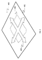
図2は、上記した形状ベースの位置決めアプローチが信頼できなくなる状態200を示す。表1は、図2に示す各表面種類についての拘束されないパラメータを示す。
FIG. 2 shows a
球状断面201の近隣の表面断面を観測しつつ、センサーの相対的な向きを決定することは不可能である。独自の解法は無い。3つの向きの自由度は、拘束されない。ほぼ平面の表面断面202が観測される場合、その平面内の2つの平行移動を一意に決定することはできない。さらに、その平面の法線ベクトルの回りの回転角度も決定することができない。回転表面203、204からの断面の観測は、拘束されない向きの角度に結びつく。標的が付された平面断面も、このカテゴリーに入る。円筒断面205の場合、円筒軸の回りの回転角度だけでなく軸に沿った1つの平行移動が、拘束されない。直線状突起206の場合、1つの平行移動方向が、拘束されない。らせん運動207の場合、回転角度および軸に沿った平行移動が制約が不十分となる。これらの場合は、通例である。
It is impossible to determine the relative orientation of the sensor while observing a surface cross section in the vicinity of the
これらの場合のうちいくつかは、さらに一般化することができる。例えば、同一の法線ベクトルを備える平面の組の観測は、平面表面の種類202に対応する。同心球または円筒断面を観測することは、球201または円筒表面の種類205が観測される状態に対応する。これは、回転または平行な直線状突起の同心表面の断面にもあてはまる。
Some of these cases can be further generalized. For example, observation of a set of planes with the same normal vector corresponds to the
これらの状態200のうちの1つが発生した場合、位置決めシステムは、位置決め信頼性を確保するために他の特性を利用する必要がある。位置決め信頼性は、完全な表面モデル内で物体の大きな表面断面を統合するための必要な条件である。テクスチャ情報を利用することまたは物体上に標的を付することが可能である。テクスチャの役割は、標的の役割と同様である。テクスチャ中の特徴点を検出し、フレーム間または現在のフレームとこれらの特徴点を含む基準モデルとの間で整合させることができる。標的により、良い精度での抽出が可能となるという利点が得られ、これにより、信頼性のあるセンサー位置決めが可能となる。
If one of these
フレームを累積しながら、拘束されない位置決めのこれらの状態の検出と誤差の防止を可能にすることは困難である。このような状態が検出された場合、本発明のシステムは、信頼性の欠如した自由度についてユーザに通知することができる。これは、リアルタイムで行うことが可能である。そして、必要なときに標的を表面へ付加することが可能になる。また、モデル化された表面全体についての診断を提供し、どこで位置決めが信頼性があるのかどこで信頼性が低いかもしくは信頼性が欠如ししているのかを示すことができる。 While accumulating frames, it is difficult to enable detection of these states of unconstrained positioning and prevention of errors. If such a condition is detected, the system of the present invention can inform the user about the degree of freedom that is unreliable. This can be done in real time. The target can then be added to the surface when needed. It can also provide diagnostics for the entire modeled surface, indicating where the positioning is reliable, where it is unreliable or lacking reliability.
Gelfandら(「Geometrically Stable Sampling for the ICP Algorithm」、Proc.International Conference on 3D Digital Imaging and Modeling、2003、pp.260−267)および「Shape Segmentation Using Local Slippage Analysis」、ACM Symposium on Geometory Processing、2004、pp.219−228において)は、3D表面の点の組からより弱い自由度を特定するための数学的ツールについての提案をしている。彼らは、方程式1を変換ベクトル(r、t)の関数として書き直している。ここで、rは、3本の正準軸x、yおよびzの回りの回転ベクトルであり、tは、3D空間中の並進ベクトルである。これは、以下の共分散行列Cの表現を得ることを可能にする。この表現は、ベクトル[ΔrT ΔtT]によってQに対する最適アライメントからのPの小さな変位の後に、方程式1中のエネルギーE(アライメント誤差)がどれくらい変化するかを特徴付ける。 Gelfand et al. ( "Geometrically Stable Sampling for the ICP Algorithm", Proc.International Conference on 3D Digital Imaging and Modeling, 2003, pp.260-267) and "Shape Segmentation Using Local Slippage Analysis", ACM Symposium on Geometory Processing, 2004, pp. 219-228) proposes a mathematical tool for identifying weaker degrees of freedom from a set of 3D surface points. They rewrite equation 1 as a function of the transformation vector (r, t). Here, r is a rotation vector around the three canonical axes x, y and z, and t is a translation vector in 3D space. This makes it possible to obtain a representation of the following covariance matrix C: This representation characterizes how the energy E (alignment error) in Equation 1 changes after a small displacement of P from the optimal alignment for Q by the vector [Δr T Δt T ].
この式中、piは、Q中の点であり、niは、Q中の対応する整合点における表面法線である。[ΔrT ΔtT]による変位後の予測されるエネルギー変化は、以下のように表される。 Where p i is a point in Q and n i is the surface normal at the corresponding matching point in Q. The expected energy change after displacement due to [Δr T Δt T ] is expressed as follows.
この増加が相対的に小さな変換は、入力組が相互にスライドし得る方向に対応するため、変換の制約が不十分である。これらの方向を特定するために、行列Cの固有ベクトルを抽出し、対応する固有値の比率を計算する。固有値がλ1からλ6へ増加していると仮定すると、以下の比率が計算される。 This relatively small increase in conversion corresponds to the direction in which the input sets can slide relative to each other, so that the conversion constraints are insufficient. In order to identify these directions, the eigenvectors of the matrix C are extracted and the ratio of the corresponding eigenvalues is calculated. Assuming that the eigenvalue increases from λ 1 to λ 6 , the following ratio is calculated:
共分散行列から良好な推定を得るために、点の正規化の後に方程式2を計算する。すなわち、これらの点をそれらの平均に対して事前に集中させ、原点への平均距離が1となるように、その変換された座標をスケーリングする。 To obtain a good estimate from the covariance matrix, equation 2 is calculated after point normalization. That is, these points are concentrated in advance with respect to their average, and the transformed coordinates are scaled so that the average distance to the origin is 1.
本発明のシステムにおいて、特徴点(例えば、標的)も観測される場合、共分散行列は、以下のように計算される。 In the system of the present invention, when a feature point (eg, target) is also observed, the covariance matrix is calculated as follows.
最も信頼性の低い自由度を特定するために、最大固有値とその他の固有値それぞれとの間の比率を考慮する。興味深いことに、図2および表1から、実際の表面の観測は、6個の自由度のうち少なくとも3個を拘束することが明らかである。これらの固有値を降順にソートしたなら、信頼性のより低い自由度の部分集合を特定するための1つの簡単な方法は、第3の固有値から、これらの順番に並べられた比率においてどこに重要なステップが存在するかを特定することにある。因数10は、これら2つの部分集合を区別し得る。また、条件数が閾値よりも高いことも確認される。例えば、この閾値は100を超え得る。固有値についての他の値または基準も利用できることは明らかである。そして、信頼性のより低い運動を表す対応する固有ベクトルが得られる。正準軸[rxryrztxtytz](ここで、rx、ryおよびrzは回転成分であり、tx、tyおよびtzは平行移動成分である)と完全にアライメントしていない固有ベクトルは、均一な平行移動と重畳された均一な回転によって構成される生成されていないらせん運動をあらわすことは、注意に値する。1つの標的が検出された場合、表面断面上の3D点および固定特徴点の組み合は、1つの回転自由度へ拘束するため、1つを超えない固有ベクトルが、高位の条件数にタグ付けすることができる。1つを超える標的が表面点と共に観測された場合、固有ベクトルをタグ付けすることはできない。この観測は、方程式3中の局所的エネルギー基準に従って姿勢を良好に拘束する。 To identify the least reliable degrees of freedom, consider the ratio between the largest eigenvalue and each of the other eigenvalues. Interestingly, from FIG. 2 and Table 1, it is clear that actual surface observations constrain at least 3 out of 6 degrees of freedom. If these eigenvalues are sorted in descending order, one simple way to identify a subset of less reliable degrees of freedom is that, from the third eigenvalue, where important in these ordered ratios, It is to identify whether a step exists. A factor of 10 can distinguish these two subsets. It is also confirmed that the condition number is higher than the threshold value. For example, this threshold can exceed 100. Obviously, other values or criteria for the eigenvalues can also be used. A corresponding eigenvector representing a less reliable motion is then obtained. Canonical axis [r x r y r z t x t y t z ] (where r x , r y and r z are rotational components and tx, ty and tz are translational components) It is worth noting that an unaligned eigenvector represents an ungenerated spiral motion composed of uniform translation and superimposed uniform rotation. If one target is detected, the combination of 3D points and fixed feature points on the surface cross-section is constrained to one rotational degree of freedom, so no more than one eigenvector tags the higher condition number. be able to. If more than one target is observed with a surface point, the eigenvector cannot be tagged. This observation better constrains the posture according to the local energy criteria in Equation 3.
それにも関わらず、小さな動き、細かい位置合わせをビュー間に想定できない場合において、対称性が可能であり対象性を特定することおよび/または分析することが可能である。例えば、PCT特許出願公開第WO 2012/168,904号には、可能な対称性を検出するための方法およびシステムが記載されている。 Nevertheless, in cases where small movements and fine alignment cannot be assumed between views, symmetry is possible and subjectivity can be identified and / or analyzed. For example, PCT Patent Application Publication No. WO 2012 / 168,904 describes a method and system for detecting possible symmetry.
信頼性最も低い自由度に対応する固有ベクトルを特定されたなら、これらの固有ベクトルの成分が分析される。各固有ベクトルは、[rx、ry、rz、tx、ty、tz]を成分とする6成分ベクトルである。これを[rt]と簡単に表す。各ベクトルはらせんを示すため、らせんのピッチにより、動きの種類の特定が支援される。ピッチの式は、以下のように表される。 Once the eigenvectors corresponding to the least reliable degrees of freedom are identified, the components of these eigenvectors are analyzed. Each eigenvector is a six-component vector having [r x , r y , r z , t x , t y , t z ] as components. This is simply expressed as [rt]. Since each vector represents a helix, the pitch of the helix helps identify the type of motion. The formula of the pitch is expressed as follows.
0のピッチは均一な回転と関連付けられる一方、極めて大きな(無限の)ピッチは平行移動に近づく。信頼性のより低い自由度のサーチ時において固有ベクトルが1つだけ特定された場合、ピッチが計算され、回転、平行移動またはらせん運動を割り当てることが可能かが決定される。これが回転である場合、観測された表面は、回転表面203および204の場合に対応する。これが平行移動である場合、観測された表面断面は、直線状突起206として挙動する。そうではない場合、これはらせん207である。
A pitch of 0 is associated with a uniform rotation, while a very large (infinite) pitch approaches translation. If only one eigenvector is identified during a search for a less reliable degree of freedom, the pitch is calculated to determine if it is possible to assign rotation, translation or helical motion. If this is a rotation, the observed surface corresponds to the case of rotating
2つの固有ベクトルが特定された場合、対応する場合は円筒205であることを確認する必要がある。1つの固有ベクトルが低ピッチでの回転を記述するのに対し、第2の固有ベクトルは、平行移動、高ピッチ値を円筒軸に沿って表現する。これらは、ピッチを用いて特定することも可能である。最後に、3つの固有ベクトルが特定される場合がある。この場合は、球201または平面202に対応する。ピッチの小さな値が計算された場合、球201の場合の3つの回転を示し、各固有ベクトルについて1つを示す。各固有ベクトルと関連付けられた回転ベクトルr1、r2およびr3は、ほぼ直交しているはずである。平面断面202の存在下において、1つの回転および2つの平行移動が特定され、それぞれ異なる固有ベクトルに属する。同一法線を用いて平面の存在を検出する方法において、点乗積ri・rj(i≠j)が計算される。これらの回転成分は全て、平面に対してほぼ平行である。絶対値は、一般的に0.9よりも高い。
When two eigenvectors are specified, it is necessary to confirm that the
平面202と球201とを区別するための別のアプローチは、現在のフレームの観測された3D点に面を当てはめることである。これは、3D点の平均を減算した後、3D点の共分散行列の固有値を抽出することにより、達成される。最小の固有値は、平面に対する法線である固有ベクトルに対応する。そして、最小の固有値に対する2番目に大きい固有値の比率に閾値を適用して、平面202と球201との間の決定をすることが可能である。それにもかかわらず、第1のアプローチの場合、平行な平面を検出するであろうから、より良好な結果が得られる。上記したように、平行な平面が観測される場合、同じく信頼性の欠如した自由度につながる。その位置を平行移動でスライドさせ、平面の共通の法線ベクトルの回りに回転させることができる。この点において、観測された表面の種類が決定されたことになる。
Another approach to distinguish between
手順900の全体が、図9Aと図9Bにまとめられている。図9Aにおいて、表面形状種類を決定するための方法の例示的なステップは、フレームの当てはめの質を推定された姿勢の変化の関数として記述する共分散行列を用いるステップ(901)と、共分散行列の固有ベクトルを抽出するステップ(903)と、固有ベクトルの対応する固有値の比率を計算するステップ(905)と、比率のうち少なくとも1つの高比率を所定の閾値を用いて特定するステップ(907)と、少なくとも1つの問題のある固有ベクトルを高比率から抽出すること(909)と、高い比率の数を決定するステップ(911)と、高比率の数を用いて表面形状の種類を決定するステップ(913)とを含む。単一の高比率がある場合、直線状突起、回転表面およびらせんのうち1つに対応する表面形状種類が決定される。高比率が2つある場合、円筒に対応する表面形状種類と確認される。高比率が3つある場合、平面および球面のうち1つに対応する表面形状の種類が決定される。 The entire procedure 900 is summarized in FIGS. 9A and 9B. In FIG. 9A, exemplary steps of the method for determining the surface shape type include using a covariance matrix (901) describing the quality of the frame fit as a function of estimated pose change, and covariance Extracting an eigenvector of the matrix (903), calculating a ratio of corresponding eigenvalues of the eigenvector (905), identifying at least one high ratio of the ratios using a predetermined threshold (907), Extracting at least one problematic eigenvector from the high ratio (909), determining the number of high ratios (911), and determining the type of surface shape using the number of high ratios (913) ). If there is a single high ratio, the surface shape type corresponding to one of the linear protrusion, rotating surface and helix is determined. When there are two high ratios, the surface shape type corresponding to the cylinder is confirmed. When there are three high ratios, the type of surface shape corresponding to one of a plane and a spherical surface is determined.
図9Bは、高い比率の数を用いて表面形状種類を決定するステップ(913)の例示的なサブステップの詳細を示す。 FIG. 9B shows details of exemplary sub-steps of determining the surface shape type (913) using a high ratio number.
可能性のある滑りを表す固有ベクトルが1つだけであるか否かが試験される(921)。試験が肯定的である場合、特定された固有ベクトルのピッチが計算され、その値について試験される(922)。ピッチが高レベル(例えば>1)である場合、表面種類が直線状突起に対応することを確認される(923)。試験が失敗した場合(922)、ピッチ値が0に近いか否か(例えば<0.1)が試験される(924)。ピッチが0に近い場合、表面種類は回転表面であり(925)、そうでは無い場合、らせんであることが確認される(926)。 It is tested (921) whether there is only one eigenvector representing a possible slip. If the test is positive, the pitch of the identified eigenvector is calculated and tested for that value (922). If the pitch is at a high level (eg> 1), it is confirmed that the surface type corresponds to a linear protrusion (923). If the test fails (922), it is tested (924) whether the pitch value is close to 0 (eg, <0.1). If the pitch is close to 0, the surface type is a rotating surface (925), otherwise it is confirmed that it is distorted (926).
共分散行列の最高固有値と比較して高比率を示す固有値が1つよりも多い場合、このような固有値が2つ有るかが試験される(927)。試験が肯定的である場合、円筒表面であることを確認される(928)。 If there is more than one eigenvalue indicating a high ratio compared to the highest eigenvalue of the covariance matrix, it is tested whether there are two such eigenvalues (927). If the test is positive, it is confirmed to be a cylindrical surface (928).
そうでは無い場合、3つの固有値が高比率を示すことが確認される(929)。試験が肯定的である場合、3つの点乗積ri・rj(i≠j)が試験される(930)。これら全てが高い(例えば>0.9)場合、平面表面種類であることが確認される(931)。そうではない場合、球状表面種類が存在することを確認する(932)。 Otherwise, it is confirmed that the three eigenvalues indicate a high ratio (929). If the test is positive, the three dot products r i · r j (i ≠ j) are tested (930). If all of these are high (eg> 0.9), it is confirmed that the surface type is a plane (931). If not, check that there is a spherical surface type (932).
最高固有値に対して高比率を有する固有値が3つを超えることは無いため、表面においてずれが無いと決定される(933)。 Since there are no more than three eigenvalues having a high ratio to the highest eigenvalue, it is determined that there is no deviation on the surface (933).
ユーザを支援するため、視覚指標を提供することができる。この視覚指標は、特定された場合に特有のものであり得る。この視覚指標は、既にユーザが利用することが可能な現在のフレームの表示上に重畳され得る。あるいは、可聴指標を用いてもよい。 A visual indicator can be provided to assist the user. This visual indicator may be unique when specified. This visual indicator can be superimposed on a display of the current frame that is already available to the user. Alternatively, an audible indicator may be used.
ユーザインターフェースにおける視覚重畳の例を図3〜図7に示す。図3において、円筒型の表示300が図示される。現在のフレーム302が物体301上に重畳される。典型的には、物体の完全取得およびモデル化の後のみに、物体全体が表示される。そのため、部分的にモデル化された物体上に現在のフレームが重畳されたようにみえる。矢印303が現在のフレームの上方に表示される。この記号303の表示により、円筒軸に沿った平行移動の動きおよび同一軸の回りの回転の信頼性がより低い可能性が示される。回転を示す矢印を、円筒301の曲率に従って曲線状にすることができる。
Examples of visual superimposition in the user interface are shown in FIGS. In FIG. 3, a
この指標303は、センサー変位時の誤差累積の回避のため、ユーザが動きをより制約すべきである旨を示す。動きを制約するための1つの方法として、標的を物体301上またはその側方に付加する方法がある。
This
図4は、平面断面401の表示400を示す。現在のフレーム402が平面401上に重畳されている様子が図示されている。ここでも、平面の部分的に累積されたモデルのみが走査プロセス時において視認可能である場合が多い。精度損失の可能性についてユーザに通知するために平行移動および法線軸双方を表示することが可能であるが、この表示を簡略化し、平行移動自由度403のみを表示してもよい。その場合、ユーザは、簡潔なグラフィカルメッセージ403から、位置決め支援のためのいくつかの特徴が無いことを理解する。絵文字403が現在のフレーム表示402上に重畳される。
FIG. 4 shows a
図5は、直線状突起表面種類501を含む表示500を示す。モデル化物体501が現在のフレーム502と共に図示されている。この場合、システムは、図示の矢印503に沿った位置決めにおいて、表面種類および信頼性の欠如を検出する。
FIG. 5 shows a
図6は、球601の表示600を示す。物体601および現在のフレーム602が図示されている。最も信頼性のある自由度の簡潔な表示603が図示されている。この場合、ロール(球に対する法線の回りの角度回転)は表示されず、有用と思われるときに表示され得る。
FIG. 6 shows a
図7は、回転表面701の表示700を示す。物体701が、重畳された現在のフレーム702と共に図示されている。矢印703は回転および暗示的にその軸を示す。この軸が暗示的に示されているのは、位置決めにおける信頼性がより低いためである。
FIG. 7 shows a
らせん207の表示は図示されていない。簡潔なバージョンにおいて、ユーザは、円筒の1つ(図3を参照)と同様の視覚フィードバックを見る。なぜならば、この場合、軸の回りの回転およびこの同一軸に沿った平行移動はどちらとも、信頼性が最も低い自由度であるからである。
The display of
他の変化および種類の視覚フィードバックが表示可能であることは明らかである。例えば、平面表面1000のための別の視覚フィードバックが図10に示されている。矢印1003は簡単な線として表示され、平面の法線ベクトルに沿って方向付けられた回転軸1004が表示される。モデル化表面1001および現在のフレーム1002が図示されている。
It is clear that other changes and types of visual feedback can be displayed. For example, another visual feedback for a
図11において、視覚フィードバック1100の別の例が図示されている。アイコン1103が表示されて、現在のフレーム1102が取得される表面上の少なくとも1つの標的の付加が提案される。ここで、表面モデル1101も表示されている。平面表面の特定の場合において、自由度を完全に拘束するために、1つ以上の標的を付加すべきである。
In FIG. 11, another example of
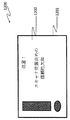
図12は、さらに別の例示的な視覚フィードバック1200を示す。視覚フィードバック1200はテキストメッセージ1201であり、ユーザへの警告メッセージ1202を含む。本例において、テキストメッセージ1201は以下のような内容である:「注意!スキャナ位置決めの信頼性が欠如しています」。本例において、ずれの性質についてのユーザへの通知は無い。スキャナ位置決めの信頼性が現在欠如している旨のみが、ユーザへ警告される。その場合、ユーザは、別の種類のフィードバックをユーザインターフェース上において起動することおよび/または単に標的をその場面に付加することを決定し得る。
視覚フィードバック
現在のフレーム上に重畳された視覚フィードバックと、任意選択的に部分的にモデル化された物体とを表示するステップについて、本明細書中において以下詳述する。
FIG. 12 shows yet another example
Visual feedback The step of displaying visual feedback superimposed on the current frame and optionally a partially modeled object is described in detail herein below.
先ず、図5に示す平行移動の場合について考える。その目的は、現在のフレームの表示上に長手方向矢印を重畳することである。矢印は、位置決めの信頼性がより低い方向に沿って方向付けられる。現在のフレームの3D点の平均(重心)が計算される。重心に最も近い3D点を特定した後、一定の任意のオフセットが、表示されているビューの光軸方向において付加される。その結果、見ている人と表面との間にある矢印の幻影を生成する。そのため、この矢印は、この位置において描写され、特定された固有ベクトルの並進ベクトル成分の方向に向けられる。矢印が図5のような幅で描写された場合、現在のフレーム中の3D点の平均法線ベクトルを計算した後、矢印の計算された方向に外積を付加する前に、そのロールを計算することができる。 First, consider the case of translation shown in FIG. Its purpose is to superimpose a longitudinal arrow on the display of the current frame. The arrows are directed along a direction with less positioning reliability. The average (centroid) of 3D points in the current frame is calculated. After identifying the 3D point closest to the center of gravity, a certain arbitrary offset is added in the optical axis direction of the displayed view. The result is an illusion of an arrow between the viewer and the surface. Therefore, this arrow is drawn at this position and is directed toward the translation vector component of the identified eigenvector. If the arrow is drawn with a width as in FIG. 5, after calculating the average normal vector of the 3D points in the current frame, calculate its roll before adding the outer product in the calculated direction of the arrow be able to.
図7に示す単一の回転の場合、固有ベクトルから回転軸の方向を特定した後、軸位置を計算する。この目的のため、軸方向を考える。なぜならば、任意の平面の法線ベクトルおよび3D点がこの平面内において突出するからである。各3D点と関連付けられた法線も、同一平面内において突出し、2Dベクトルを得る。各突出点およびその突出法線により、突起平面内の線が規定される。この探索軸は、線の組全体に対する平方距離の合計を最小化するこの点においてこの平面と公差する。これらの距離それぞれに対し、重みも付加される。この重みは、各点と関連付けられた突出法線ベクトルの長さに比例するように設定される。より詳細には、以下のようにしてXをサーチする。 In the case of the single rotation shown in FIG. 7, after specifying the direction of the rotation axis from the eigenvector, the axis position is calculated. For this purpose, consider the axial direction. This is because the normal vector and 3D point of an arbitrary plane protrude in this plane. The normals associated with each 3D point also protrude in the same plane to obtain a 2D vector. Each protrusion point and its protrusion normal define a line in the protrusion plane. This search axis is tolerant with this plane at this point which minimizes the sum of square distances for the entire set of lines. A weight is also added to each of these distances. This weight is set to be proportional to the length of the protruding normal vector associated with each point. More specifically, X is searched as follows.
式中、Xは、平面aiにおいて求められる2D点であり、ciは、直線のパラメータであり、wiは、各点と関連付けられた重みである。発見された点Xおよび回転軸の方向から、軸が3Dに設定される。曲線矢印の中心が計算された回転軸となるように、曲線矢印が位置決めされる。本例において、曲率半径は固定されるが、3D点の関数(例えば、回転軸の回りの慣性)に基づいて調節することが可能であることは明らかである。この軸に沿って、矢印は、軸上の点の重心の突起に配置される。最後に、例えばノイズに起因するあるフレームから他のフレームへの軸の回りにおける振動を回避するため、センサーのy軸に対応するベクトルを、矢印が描写されている平面内において突出させる。同じことを曲線矢印の固有のy軸について行った後、後者の突出したy軸をセンサーの突出したy軸とアライメントをとる。このようにして、曲線矢印のクロッキングは、観測表面に対するセンサー視点に依存する。 Where X is a 2D point determined in plane a i , c i is a straight line parameter, and w i is the weight associated with each point. From the found point X and the direction of the axis of rotation, the axis is set to 3D. The curved arrow is positioned so that the center of the curved arrow becomes the calculated rotation axis. In this example, the radius of curvature is fixed, but it is clear that it can be adjusted based on a 3D point function (eg, inertia around the axis of rotation). Along this axis, an arrow is placed on the protrusion at the center of gravity of the point on the axis. Finally, in order to avoid vibrations around the axis from one frame to the other, for example due to noise, a vector corresponding to the y-axis of the sensor is projected in the plane in which the arrows are drawn. After doing the same for the unique y-axis of the curved arrow, the latter protruding y-axis is aligned with the protruding y-axis of the sensor. In this way, the clocking of the curved arrow depends on the sensor viewpoint with respect to the observation surface.
図3に示す円筒の場合、回転表面に適用される手順を適用して、回転軸を決定する。その後、円筒曲率が推定される。その結果、表示されたクロス矢印を曲げることが可能になる。そのために、曲率半径を3D点の組全体から推定する。この半径は、それらの点と円筒軸との間の平均距離に等しくされる。最後に、円筒の視認可能な表面がセンサー視点に対して凸状または凹状にみえるかを決定する。そのために、3D点の重心を計算し、最も近い3D点を特定する。特定された最も近い3D点が計算された重心よりもセンサーに近い場合、円筒は凸状にみえる。そうではない場合、凹状にみえる。この窪みは、単に指標である。同じ軸を共有する円筒の同軸の断面を観測することができ、これらの円筒は、センサー視点に対して全て凹状でなくてもよい。それにもかかわらず、曲率の計算された半径は、それぞれ凸状または凹状であるかによってわずかに増減する。この半径は、20%程度増減させられる。その結果、重畳されたクロス矢印を表示後に完全に視認可能とすることができる。 In the case of the cylinder shown in FIG. 3, the procedure applied to the rotating surface is applied to determine the axis of rotation. Thereafter, the cylindrical curvature is estimated. As a result, the displayed cross arrow can be bent. For this purpose, the radius of curvature is estimated from the entire set of 3D points. This radius is made equal to the average distance between those points and the cylinder axis. Finally, it is determined whether the visible surface of the cylinder looks convex or concave with respect to the sensor viewpoint. Therefore, the center of gravity of the 3D point is calculated, and the closest 3D point is specified. If the identified closest 3D point is closer to the sensor than the calculated center of gravity, the cylinder will appear convex. If not, it looks concave. This depression is merely an indicator. Coaxial cross sections of cylinders sharing the same axis can be observed, and these cylinders need not be all concave with respect to the sensor viewpoint. Nevertheless, the calculated radius of curvature slightly increases or decreases depending on whether it is convex or concave, respectively. This radius is increased or decreased by about 20%. As a result, the superimposed cross arrow can be made completely visible after being displayed.
図4に示す平面断面の場合、クロス矢印も用いられる。直線状突起について述べた手順と同じ手順に従って、クロス位置を計算する。2つの方向は直交している。平面に対して法線である軸の回りの、例えばノイズに起因する可能性のある振動を回避するために、回転表面のための単一の回転の場合における向きを安定化させる同じ手順が用いられる。クロスの法線ベクトルを、3D点と関連付けられた平均法線として計算することができる。これは、関連付けられた回転成分の並数が最大である固有ベクトルの回転成分(ri)として得ることも可能である。 In the case of the plane cross section shown in FIG. 4, a cross arrow is also used. The cross position is calculated according to the same procedure as described for the linear protrusion. The two directions are orthogonal. The same procedure is used to stabilize the orientation in the case of a single rotation for the rotating surface to avoid vibrations around an axis that is normal to the plane, for example due to noise. It is done. The cross normal vector can be calculated as the average normal associated with the 3D point. This can also be obtained as the rotation component (r i ) of the eigenvector with the maximum number of associated rotation components.
球状断面の場合が特定された後、標準的な最小二乗方法に基づいて、1組の3D点に球を当てはめる。この手順から、中心および半径が得られる。同様に、円筒の場合について行われ、曲率がセンサー視点に対して凹状または凸状に分類され、表示目的のために半径を増減させる。曲線状のクロス矢印は、重心に対して最も近い3D点に配置される。それは、先ず、法線ベクトルが3D点と関連付けられた平均法線に基づいて決定される平面に向けられる。その後、この平面内において、単一の回転の場合に用いた手順と同じ手順を用いてクロスの向きを安定させる。同じ理由によって、これは、フレーム間のノイズに起因する振動が防止する。 After the case of a spherical cross-section is identified, a sphere is fitted to a set of 3D points based on a standard least squares method. From this procedure, the center and radius are obtained. Similarly, for the case of a cylinder, the curvature is classified as concave or convex with respect to the sensor viewpoint, and the radius is increased or decreased for display purposes. A curved cross arrow is placed at the 3D point closest to the center of gravity. It is first directed to a plane in which the normal vector is determined based on the average normal associated with the 3D point. Then, in this plane, the direction of the cloth is stabilized using the same procedure as that used in the case of a single rotation. For the same reason, this prevents vibrations due to noise between frames.
物体を走査しながら、上記した視覚指標を作動させることができる。信頼性のより低い自由度が特定された場合、位置決めアラームを作動させるために矢印を表示することができる。これらの矢印は、例えば赤色に着色することができる。ユーザは、標的を物体またはその環境に付加し、走査物体の走査を継続し得る。信頼性のより低い自由度が無くなった場合、視覚指標の表示が停止される。そうではない場合、同様のまたは異なる視覚指標が表示され得る。 The visual indicator described above can be activated while scanning the object. If a less reliable degree of freedom is identified, an arrow can be displayed to activate a positioning alarm. These arrows can be colored red, for example. The user can add the target to the object or its environment and continue scanning the scanned object. When the degree of freedom with lower reliability disappears, the display of the visual index is stopped. Otherwise, similar or different visual indicators may be displayed.
一実施形態において、システムは、位置決め信頼性が確保されるまでは、3D点の新たに観測されたフレームを物体表面の累積モデルへ付加しない。これは、誤って配置されたフレームを用いたモデルの汚染を防止する。 In one embodiment, the system does not add a newly observed frame of 3D points to the cumulative model of the object surface until positioning reliability is ensured. This prevents contamination of the model with misplaced frames.
一実施形態において、信頼性のより低い自由度を特定するためのより厳格な閾値を用いて、ユーザへ警告を表示することができる。この警告は、同じ矢印だが色が異なる(例えば、黄色の)矢印を用いて表示することができる。その結果、ユーザの注意を、(累積されたモデルへの影響が壊滅的になる前に解消することが可能な)可能性のある位置決め信頼性の問題に向けることが可能になる。 In one embodiment, a warning can be displayed to the user with a stricter threshold to identify a less reliable degree of freedom. This warning can be displayed using arrows with the same arrow but different colors (eg, yellow). As a result, the user's attention can be directed to potential positioning reliability issues (which can be resolved before the impact on the accumulated model becomes devastating).
ノイズおよび視点問題に起因して、共分散行列値における変化が可能になり、その結果、固有値比率が閾値に近い場合に視覚フィードバックがちらつく場合がある。このようなちらつきを防止するため、時間的なフィルタリングを用いることができる。それを行うための一つの方法は、n個の最新のフレームに対するアラーム数をカウントし、視覚フィードバックアラームを作動させる前に、現在のフレームを含んで、所定の閾値を超えるフレームがいつ問題となるかを決定することである。例えば、閾値は、n個の最新のフレーム中のn/2フレームであり得る。フレームレートが15Hzに近い場合、nの典型的な値は20である。検討されたフレーム数は、1秒内に取得されたフレーム数を少し上回る。
診断モード
信頼性のより低い自由度を分析することにより、ユーザによる物体走査を支援できる、極めて興味深い可能性が得られる。例えば、体積表面を再構築する枠組みにおいて、次のように、3D取得点によって変更された全ボクセル中の条件数の平均を累積および更新することができる。
Due to noise and viewpoint problems, changes in the covariance matrix values are possible, and as a result, visual feedback may flicker when the eigenvalue ratio is close to the threshold. Temporal filtering can be used to prevent such flickering. One way to do that is to count the number of alarms for the n most recent frames, and when the visual feedback alarm is activated, frames that exceed a predetermined threshold, including the current frame, become a problem. Is to decide. For example, the threshold may be n / 2 frames in the n most recent frames. A typical value of n is 20 when the frame rate is close to 15 Hz. The number of frames considered is slightly higher than the number of frames acquired in one second.
Diagnostic Mode Analyzing the less reliable degrees of freedom provides a very interesting possibility that can assist the user in scanning the object. For example, in the framework of reconstructing the volume surface, the average of the condition numbers in all voxels modified by the 3D acquisition point can be accumulated and updated as follows.
![]()
![]()
式中、Wtは、時間ステップtにおける共分散行列の条件数であり、信頼性の欠如した姿勢推定の非信頼性のレベルを提供する。パラメータβは、メモリを制御する定数であり、現在の値および前回の値を重み付けする。βの典型的な値は0.5である。条件数の平均は、ボクセル感度レベルである。リアルタイムまたは走査後の走査の間、平均条件数またはボクセル感度レベルに対応する色でモデルを表示することが可能である。色付きモデル800の一例を図8に示す。物体802が表示され、位置決め信頼性に問題があると特定された断面が、1つの色801で表示される(図8では、パターンが示されている)。一方、問題のあることに近い断面は、別の色803で表示される(図8中の別のパターン)。上記したような診断モードにおいて、システムは、モデル中のフレームを(問題があると判断される場合であっても)統合する。その結果、モデル化物体をグローバルに視覚化した後、ユーザは、標的を付加する決定や物体またはそのいくつかの断面を再走査する決定を下すことができる。
Where W t is the condition number of the covariance matrix at time step t and provides an unreliable level of pose estimation that is unreliable. The parameter β is a constant that controls the memory, and weights the current value and the previous value. A typical value for β is 0.5. The average of the condition numbers is the voxel sensitivity level. During real-time or post-scan scanning, the model can be displayed in a color corresponding to the average condition number or voxel sensitivity level. An example of the
図14Aおよび図14Bは、センサーの計算された位置および向きが領域内に逸脱している場合の、形状ベースの位置決めの可能性のある結果1400を示す。14Aには、基準モデル1404が図示されている。図14Bでは、1403の近くの領域1401での表面のずれに起因して、ゆがんだモデル1402が取得されている。
14A and 14B show a
別の診断モードにおいて、モデルは累積されていない。システムは、姿勢信頼性を分析する。この分析は、現在のフレームまたはいくつかのフレーム(典型的には20個未満のフレーム)のみに基づいて行われ、いかなるモデルも累積しない。診断モードのための例示的な視覚フィードバック1300が図13に図示される。視覚フィードバック1300は、図5に示すものと同様である。矢印1302および現在のフレーム1301が図示されているが、ここではモデルは図示されていない。
例示的なシステム実施形態
図15は、位置決めの非信頼性についての指標を提供するためのシステム1500の例示的な構成要素のブロック図である。本システムは、スキャナ1501を含む。スキャナ1501は、物体の表面形状を走査することと、複数のフレームの各フレームについて、スキャナのための形状ベースの位置決めを用いて1組の3D点を累積することとを行う。スキャナは、姿勢推定器1503を含む。姿勢推定器1503は、スキャナのために推定された姿勢を3D点を用いて推定する。非信頼性姿勢検出器1505は、推定された姿勢が拘束されない位置決めを有するかどうかを決定し、推定された姿勢が拘束されない位置決めを有する場合は、この推定された姿勢を信頼性の欠如した姿勢推定として特定する。指標生成器1507は、信頼性の欠如した姿勢推定が検出された旨の指標を生成する。
In another diagnostic mode, the model is not cumulative. The system analyzes posture reliability. This analysis is based on the current frame or only a few frames (typically less than 20 frames) and does not accumulate any model. An exemplary
Exemplary System Embodiment FIG. 15 is a block diagram of exemplary components of a
一実施形態において、システム1500は、自由度識別子1509をさらに含む。自由度識別子1509は、推定された姿勢において、問題のある自由度を少なくとも1つ特定する。自由度識別子は、非信頼性姿勢検出器1505によってトリガされ、指標生成器1507によって生成された指標は、少なくとも1つの問題のある自由度についての情報を指標と共に含む。
In one embodiment,
一実施形態において、指標生成器1507によって生成された指標は、問題のある自由度全てについての情報を含む。
In one embodiment, the index generated by the
一実施形態において、システム1500は、特徴点検出器1511をさらに含む。特徴点検出器1511は、スキャナ1501により再観察可能な特徴点の存在を複数のフレームのうち少なくとも2つにおいて検出する。姿勢推定器1503は、特徴点を3D点と共に用いて、推定された姿勢を推定する。非信頼性姿勢検出器1505は、特徴点を用いて、推定された姿勢を信頼性の欠如した姿勢推定として特定する。特徴点検出器1511は、特徴点のモデルを累積して、再観察可能な特徴点の検出をフレーム内において行う。
In one embodiment, the
一実施形態において、システム1500は、スピーカ1513をさらに含む。指標生成器1507は、スピーカ1513に可聴指標を出させる。
In one embodiment,
一実施形態において、システム1500は、視覚インターフェース1515をさらに含む。指標生成器1507は、視覚インターフェース1515に視覚指標を表示させる。視覚指標は、テキストメッセージおよびグラフィカルメッセージのうちの少なくとも1つである。
In one embodiment,
一実施形態において、システム1500は、モデルビルダ1517をさらに含む。モデルビルダ1517は、表面の形状の累積モデルを1組の3D点を用いて構築する。視覚インターフェース1515は、累積モデルのグラフィカル表示を表示し、視覚指標は、累積モデルのグラフィカル表示上に重畳される。
In one embodiment,
一実施形態において、システム1500は、ボクセル感度レベル計算器1519をさらに含む。ボクセル感度レベル計算器1519は、1組の3D点によって変更された累積モデルの全ボクセルにおけるボクセル感度レベルの平均を累積する。視覚インターフェース1515は、累積モデルのグラフィカル表示をボクセル感度レベルに対応する色と共に表示する。
In one embodiment,
一実施形態において、システム1500は、フレーム選択器1521をさらに含む。フレーム選択器1521は、信頼性の欠如した姿勢の推定の信頼性の欠如のレベルを決定することと、信頼性の欠如レベルと所定の信頼性の欠如閾値と比較することと、信頼性の欠如レベルが所定の信頼性の欠如閾値よりも低い場合にのみ、各フレームの1組の3D点をモデルビルダ1517へ転送することとを行う。別の実施形態において、フレーム選択器1521は、全フレームの全ての組の3D点を信頼性の欠如レベルの指標と共にモデルビルダー1517へ転送する。フレーム選択器1521は、信頼性の欠如レベルを認定するために1つまたは多数の信頼性の欠如閾値を用いた比較を行って、信頼性の欠如レベルの指標を準備する。さらに別の実施形態において、スキャナ1501は、モデルビルダ1517と通信して、全フレームの1組の3D点を転送する。フレーム選択器1521は、信頼性の欠如した姿勢推定の信頼性の欠如レベルを決定し、この情報をモデルビルダ1517へ通信する。
In one embodiment,
一実施形態において、視覚インターフェース1515は、走査の現在のフレームのグラフィカル表示を表示し、視覚指標は、現在のフレームのグラフィカル表示上に重畳される。
In one embodiment, the
一実施形態において、システム1500は、姿勢感度レベル属性付加器1523をさらに含む。姿勢感度レベル属性付加器1523は、推定された姿勢を用いて姿勢感度レベルを推定された姿勢へ属性付加する。姿勢感度レベル属性付加器1523は、非信頼性姿勢検出器1505によってトリガされる。指標生成器1507によって生成された指標は、姿勢感度レベルについての情報を指標と共に含み、姿勢感度レベルについての情報は、視覚指標の色である。
In one embodiment,
一実施形態において、システム1500は、自由度識別子1525をさらに含む。自由度識別子1525は、推定された姿勢において問題のある自由度を少なくとも1つを特定する。信頼性の欠如した自由度識別子1525は、非信頼性姿勢検出器1505によってトリガされる。指標生成器1507によって生成された指標は、少なくとも1つの問題のある自由度についての情報を指標と共に含み、グラフィカルメッセージは、少なくとも1つの矢印を含み、矢印は、問題のある自由度に対応する向きと共に表示される。
In one embodiment,
一実施形態において、システム1500は、ユーザコマンドインターフェース1527をさらに含む。ユーザコマンドインターフェース1527は、位置決め信頼性の検証を行うためのコマンドをユーザから受信し、非信頼性姿勢検出器1505および指標生成器1507は、信頼性の欠如した姿勢推定が検出された旨の指標を生成せよとのコマンドによってトリガされる。
In one embodiment,
一実施形態において、システム1500は、時間的フィルタ1529をさらに含む。時間的フィルタ1529は、複数のフレームのn個の最新のフレーム中の信頼性の欠如した姿勢推定を有するフレーム数が所定の閾値に到達した場合、指標生成器1507による指標の生成をトリガする。
In one embodiment,
上記の記載は、本発明者らが現在企図している例示的な実施形態に関連するが、本発明の広範な側面において、本明細書中に記載の要素の均等物が含まれることが理解される。 Although the above description relates to exemplary embodiments currently contemplated by the inventors, it is understood that in a broad aspect of the invention the equivalents of the elements described herein are included. Is done.
上記した実施形態は、ひとえに例示的なものである。よって、本発明の範囲は、添付の特許請求の範囲によって限定されることが意図される。 The above-described embodiments are merely exemplary. Accordingly, it is intended that the scope of the invention be limited by the appended claims.
Claims (15)
物体の表面形状を走査し、当該スキャナのための形状ベースの位置決めを用いて複数のフレームの各フレームについて1組の3D点を累積するスキャナと、
前記3D点を用いて、前記物体に関する前記スキャナの推定姿勢を推定する姿勢推定器と、
前記推定姿勢が拘束されない位置決めを有するかどうかを決定し、前記推定姿勢が拘束されない位置決めを有する場合には、前記推定姿勢を信頼性の欠如した姿勢推定として特定する非信頼性姿勢検出器と、
前記信頼性の欠如した姿勢推定が検出された旨の指標を生成する指標生成器とを有し、さらに、
6×6の共分散行列を用いて、前記推定姿勢において少なくとも1つ問題のある自由度を、6つの自由度の中から特定する自由度識別子をさらに有し、前記共分散行列は、前記推定姿勢の変化の関数としてフレームの当てはめの質を記述し、前記自由度識別子は、前記非信頼性姿勢検出器によってトリガされ、前記少なくとも1つ問題のある自由度は、前記拘束されない位置決めをもたらし、前記指標生成器によって生成された前記指標は、前記指標に前記少なくとも1つの問題のある自由度の全てについての情報を含む、システム。 A system that provides an indication of the lack of positioning reliability,
A scanner that scans the surface shape of the object and accumulates a set of 3D points for each frame of the plurality of frames using shape-based positioning for the scanner;
A posture estimator that estimates the estimated posture of the scanner with respect to the object using the 3D points;
Determining whether the estimated posture has unconstrained positioning, and if the estimated posture has unconstrained positioning, an unreliable posture detector that identifies the estimated posture as a posture estimation lacking reliability;
An index generator for generating an index indicating that the unreliable posture estimation is detected, and
A 6 × 6 covariance matrix is used to further include a degree of freedom identifier that identifies at least one problematic degree of freedom in the estimation posture from among the six degrees of freedom, and the covariance matrix includes Describes the quality of the frame fit as a function of attitude changes, the degree of freedom identifier is triggered by the unreliable attitude detector, and the at least one problematic degree of freedom results in the unconstrained positioning; The index generated by the index generator includes information about all of the at least one problematic degrees of freedom in the index.
前記グラフィカルメッセージは、前記問題のある自由度に対応する向きと共に表示される少なくとも1つの矢印を含む請求項5から請求項10のうちいずれか1項に記載のシステム。 A degree of freedom identifier identifying at least one problematic degree of freedom in the estimated pose, wherein the unreliable degree of freedom identifier is triggered by the unreliable posture detector, and the indicator generator The indicator generated by includes together with the indicator information about at least one problematic degree of freedom;
11. A system according to any one of claims 5 to 10, wherein the graphical message includes at least one arrow displayed with an orientation corresponding to the problematic degree of freedom.
物体の表面形状を走査し、当該スキャナのための形状ベースの位置決めを用いて複数のフレームの各フレームについて1組の3D点を累積することと、
前記3D点を用いて前記物体に関する前記スキャナの推定姿勢を推定することと、
前記推定姿勢が拘束されない位置決めを有するかどうかを決定し、前記推定姿勢が拘束されない位置決めを有する場合には、前記推定姿勢を信頼性の欠如した姿勢推定として特定することと、
6×6の共分散行列から抽出された固有ベクトルを用いて、6つの自由度の中から、前記推定姿勢において少なくとも1つ問題のある自由度を特定することとを含み、前記共分散行列は、前記推定姿勢の変化の関数としてフレームの当てはめの質を記述し、前記自由度を特定することは、前記推定姿勢が拘束されない位置決めを有するかどうかを決定することによってトリガされ、
前記信頼性の欠如した姿勢推定が検出された旨の指標を生成すること
をさらに含み、前記指標は、前記少なくとも1つ問題のある自由度のすべてについての情報を含む、方法。 A method for providing an indication of a lack of positioning reliability,
Scanning the surface shape of the object and accumulating a set of 3D points for each frame of the plurality of frames using shape-based positioning for the scanner;
Estimating the estimated posture of the scanner with respect to the object using the 3D points;
Determining whether the estimated attitude has unconstrained positioning, and if the estimated attitude has unconstrained positioning, identifying the estimated attitude as an unreliable attitude estimate;
Identifying at least one problematic degree of freedom in the estimated pose from among the six degrees of freedom using eigenvectors extracted from a 6 × 6 covariance matrix, wherein the covariance matrix comprises: Describes the quality of the frame fit as a function of changes in the estimated pose, and specifying the degrees of freedom is triggered by determining whether the estimated pose has unconstrained positioning;
The method further includes generating an indication that the unreliable pose estimate has been detected, the indicator including information about all of the at least one problematic degrees of freedom.
前記固有ベクトルの対応する固有値の比率を計算し、
所定の閾値を用いて、前記比率のうち少なくとも1つの高い比率を特定し、
前記高い比率から、少なくとも1つの問題のある固有ベクトルを抽出し、
ただ一つの高い比率がある場合には、前記表面形状の種類を決定して、直線状突起、回転表面およびらせんのうち1つに対応させ、
高い比率が2つある場合には、前記表面形状の種類を確認し円筒に対応させ、
高い比率が3つある場合には、前記表面形状の種類を決定し平面および球のうち1つに対応させることによって表面の形状の種類を決定することを含む請求項14に記載の方法。 Determining whether the estimated pose has unconstrained positioning;
Calculating the ratio of the corresponding eigenvalues of the eigenvector;
Identify a high ratio of at least one of the ratios using a predetermined threshold;
Extracting at least one problematic eigenvector from the high ratio;
If there is only one high ratio, determine the type of surface shape to correspond to one of linear protrusion, rotating surface and helix,
If there are two high ratios, check the type of surface shape and make it correspond to a cylinder.
15. The method of claim 14, including determining the surface shape type by determining the surface shape type and corresponding to one of a plane and a sphere if there are three high ratios.
Applications Claiming Priority (3)
| Application Number | Priority Date | Filing Date | Title |
|---|---|---|---|
| US201261672858P | 2012-07-18 | 2012-07-18 | |
| US61/672,858 | 2012-07-18 | ||
| PCT/IB2013/055258 WO2014013363A1 (en) | 2012-07-18 | 2013-06-26 | 3-d scanning and positioning interface |
Publications (2)
| Publication Number | Publication Date |
|---|---|
| JP2015524560A JP2015524560A (en) | 2015-08-24 |
| JP6267700B2 true JP6267700B2 (en) | 2018-01-24 |
Family
ID=49948361
Family Applications (1)
| Application Number | Title | Priority Date | Filing Date |
|---|---|---|---|
| JP2015522189A Active JP6267700B2 (en) | 2012-07-18 | 2013-06-26 | 3D scanning and positioning interface |
Country Status (6)
| Country | Link |
|---|---|
| US (2) | US10401142B2 (en) |
| EP (1) | EP2875314B1 (en) |
| JP (1) | JP6267700B2 (en) |
| CN (1) | CN104335006B (en) |
| CA (1) | CA2875754C (en) |
| WO (1) | WO2014013363A1 (en) |
Families Citing this family (14)
| Publication number | Priority date | Publication date | Assignee | Title |
|---|---|---|---|---|
| US10073531B2 (en) | 2015-10-07 | 2018-09-11 | Google Llc | Electronic device pose identification based on imagery and non-image sensor data |
| US11567201B2 (en) | 2016-03-11 | 2023-01-31 | Kaarta, Inc. | Laser scanner with real-time, online ego-motion estimation |
| WO2017155970A1 (en) | 2016-03-11 | 2017-09-14 | Kaarta, Inc. | Laser scanner with real-time, online ego-motion estimation |
| US11573325B2 (en) | 2016-03-11 | 2023-02-07 | Kaarta, Inc. | Systems and methods for improvements in scanning and mapping |
| US10989542B2 (en) | 2016-03-11 | 2021-04-27 | Kaarta, Inc. | Aligning measured signal data with slam localization data and uses thereof |
| JP6598814B2 (en) | 2017-04-05 | 2019-10-30 | キヤノン株式会社 | Information processing apparatus, information processing method, program, system, and article manufacturing method |
| EP3646058A4 (en) * | 2017-06-30 | 2020-12-02 | Kaarta, Inc. | Systems and methods for improvements in scanning and mapping |
| WO2019099605A1 (en) | 2017-11-17 | 2019-05-23 | Kaarta, Inc. | Methods and systems for geo-referencing mapping systems |
| WO2019165194A1 (en) | 2018-02-23 | 2019-08-29 | Kaarta, Inc. | Methods and systems for processing and colorizing point clouds and meshes |
| WO2019195270A1 (en) | 2018-04-03 | 2019-10-10 | Kaarta, Inc. | Methods and systems for real or near real-time point cloud map data confidence evaluation |
| WO2020009826A1 (en) | 2018-07-05 | 2020-01-09 | Kaarta, Inc. | Methods and systems for auto-leveling of point clouds and 3d models |
| WO2023220804A1 (en) * | 2022-05-20 | 2023-11-23 | Creaform Inc. | 3d scanner with structured light pattern projector and method of using same for performing light pattern matching and 3d reconstruction |
| WO2023220805A1 (en) * | 2022-05-20 | 2023-11-23 | Creaform Inc. | System, apparatus and method for performing a 3d surface scan and/or texture acquisition using rolling shutter cameras |
| WO2023225754A1 (en) * | 2022-05-27 | 2023-11-30 | Creaform Inc. | System, apparatus and method for providing 3d surface measurements with precision indication capabilities and use thereof |
Family Cites Families (56)
| Publication number | Priority date | Publication date | Assignee | Title |
|---|---|---|---|---|
| US5561526A (en) | 1994-05-26 | 1996-10-01 | Lockheed Missiles & Space Company, Inc. | Three-dimensional measurement device and system |
| JP3738456B2 (en) | 1994-11-14 | 2006-01-25 | マツダ株式会社 | Article position detection method and apparatus |
| DE69726025T2 (en) | 1996-06-13 | 2004-09-16 | K.U. Leuven Research & Development | METHOD AND DEVICE FOR OBTAINING A THREE-DIMENSIONAL SHAPE |
| JPH1021401A (en) | 1996-07-04 | 1998-01-23 | Canon Inc | Three-dimensional information processor |
| JP3113827B2 (en) * | 1996-11-28 | 2000-12-04 | インターナショナル・ビジネス・マシーンズ・コーポレ−ション | Method and apparatus for recognizing rectangular object |
| GB2353659A (en) | 1998-05-15 | 2001-02-28 | Tricorder Technology Plc | Method and apparatus for 3D representation |
| US6137491A (en) * | 1998-06-05 | 2000-10-24 | Microsoft Corporation | Method and apparatus for reconstructing geometry using geometrically constrained structure from motion with points on planes |
| US6748112B1 (en) | 1998-07-28 | 2004-06-08 | General Electric Company | Method and apparatus for finding shape deformations in objects having smooth surfaces |
| JP2000175176A (en) * | 1998-12-04 | 2000-06-23 | Hitachi Ltd | Supervisory method for mobile object and image supervisory device |
| JP4167390B2 (en) * | 2000-11-20 | 2008-10-15 | 日本電気株式会社 | Object collation method, object collation apparatus, and recording medium recording the program |
| US6578869B2 (en) * | 2001-03-26 | 2003-06-17 | Trw Inc. | Vehicle occupant position sensor utilizing image focus attributes |
| US6700668B2 (en) | 2002-06-25 | 2004-03-02 | General Electric Company | Method of measuring a part with a wide range of surface reflectivities |
| WO2004015369A2 (en) | 2002-08-09 | 2004-02-19 | Intersense, Inc. | Motion tracking system and method |
| US6985238B2 (en) | 2002-09-25 | 2006-01-10 | General Electric Company | Non-contact measurement system for large airfoils |
| US7639741B1 (en) * | 2002-12-06 | 2009-12-29 | Altera Corporation | Temporal filtering using object motion estimation |
| US7408986B2 (en) * | 2003-06-13 | 2008-08-05 | Microsoft Corporation | Increasing motion smoothness using frame interpolation with motion analysis |
| JP3779308B2 (en) | 2004-07-21 | 2006-05-24 | 独立行政法人科学技術振興機構 | Camera calibration system and three-dimensional measurement system |
| US7447558B2 (en) | 2004-09-18 | 2008-11-04 | The Ohio Willow Wood Company | Apparatus for determining a three dimensional shape of an object |
| US8473124B2 (en) * | 2004-11-08 | 2013-06-25 | Textron Innovations Inc. | Flight control system having a three control loop design |
| US7684602B2 (en) * | 2004-11-18 | 2010-03-23 | Siemens Medical Solutions Usa, Inc. | Method and system for local visualization for tubular structures |
| CN101189487B (en) | 2005-03-11 | 2010-08-11 | 形创有限公司 | Auto-referenced system and apparatus for three-dimensional scanning |
| US8082120B2 (en) | 2005-03-11 | 2011-12-20 | Creaform Inc. | Hand-held self-referenced apparatus for three-dimensional scanning |
| WO2006120759A1 (en) * | 2005-05-12 | 2006-11-16 | Techno Dream 21 Co., Ltd. | 3-dimensional shape measuring method and device thereof |
| US7275008B2 (en) | 2005-09-02 | 2007-09-25 | Nokia Corporation | Calibration of 3D field sensors |
| WO2007056541A2 (en) | 2005-11-08 | 2007-05-18 | Young Garrett J | Apparatus and method for generating light from multi - primary colors |
| CN101466998B (en) | 2005-11-09 | 2015-09-16 | 几何信息学股份有限公司 | The method and apparatus of absolute-coordinate three-dimensional surface imaging |
| JP4650752B2 (en) * | 2005-12-16 | 2011-03-16 | 株式会社Ihi | Self-position identification method and apparatus and three-dimensional shape measurement method and apparatus |
| US7567713B2 (en) * | 2006-02-08 | 2009-07-28 | Mitutoyo Corporation | Method utilizing intensity interpolation for measuring edge locations in a high precision machine vision inspection system |
| US20070201859A1 (en) | 2006-02-24 | 2007-08-30 | Logitech Europe S.A. | Method and system for use of 3D sensors in an image capture device |
| EP2096403B1 (en) | 2006-04-27 | 2011-01-26 | 3D Scanners Ltd | Optical scanning probe with a variable aperture at the light projector |
| EP1872715B1 (en) * | 2006-06-30 | 2009-05-13 | General Electric Company | Method and system for multi-channel biosignal processing |
| US8090194B2 (en) | 2006-11-21 | 2012-01-03 | Mantis Vision Ltd. | 3D geometric modeling and motion capture using both single and dual imaging |
| US7768655B2 (en) | 2006-12-20 | 2010-08-03 | General Electric Company | Methods and system for measuring an object |
| WO2008078744A1 (en) | 2006-12-25 | 2008-07-03 | Nec Corporation | Distance measuring device, method, and program |
| DE102007022361A1 (en) | 2007-05-04 | 2008-11-06 | Friedrich-Schiller-Universität Jena | Device and method for the contactless detection of spatial coordinates of a surface |
| US8172407B2 (en) | 2007-05-16 | 2012-05-08 | Honda Motor Co., Ltd. | Camera-projector duality: multi-projector 3D reconstruction |
| CN100554873C (en) | 2007-07-11 | 2009-10-28 | 华中科技大学 | A kind of based on two-dimensional encoded 3 D measuring method |
| US7768656B2 (en) | 2007-08-28 | 2010-08-03 | Artec Group, Inc. | System and method for three-dimensional measurement of the shape of material objects |
| JP5412169B2 (en) | 2008-04-23 | 2014-02-12 | 株式会社日立ハイテクノロジーズ | Defect observation method and defect observation apparatus |
| WO2010015086A1 (en) | 2008-08-06 | 2010-02-11 | Creaform Inc. | System for adaptive three-dimensional scanning of surface characteristics |
| US8139867B2 (en) * | 2008-12-05 | 2012-03-20 | Tandent Vision Science, Inc. | Image segregation system architecture |
| US20100142846A1 (en) * | 2008-12-05 | 2010-06-10 | Tandent Vision Science, Inc. | Solver for image segregation |
| US8139850B2 (en) * | 2008-12-05 | 2012-03-20 | Tandent Vision Science, Inc. | Constraint generation for use in image segregation |
| US8260050B2 (en) * | 2008-12-05 | 2012-09-04 | Tandent Vision Science, Inc. | Test bed for optimizing an image segregation |
| JP5602392B2 (en) | 2009-06-25 | 2014-10-08 | キヤノン株式会社 | Information processing apparatus, information processing method, and program |
| CN101620676B (en) | 2009-07-02 | 2012-05-23 | 浙江省电力公司 | Fast image recognition method of insulator contour |
| KR20110097140A (en) | 2010-02-24 | 2011-08-31 | 삼성전자주식회사 | Apparatus for estimating location of moving robot and method thereof |
| JP5625490B2 (en) | 2010-05-25 | 2014-11-19 | セイコーエプソン株式会社 | Projector, projection state adjustment method, and projection state adjustment program |
| CN102042814B (en) | 2010-06-24 | 2012-03-07 | 中国人民解放军国防科学技术大学 | Projection auxiliary photographing measurement method for three-dimensional topography of large storage yard |
| CN102338616B (en) | 2010-07-22 | 2016-08-17 | 首都师范大学 | Three-dimensional rotation scanning measurement system and method in conjunction with positioning and orientation system |
| JP4940461B2 (en) * | 2010-07-27 | 2012-05-30 | 株式会社三次元メディア | 3D object recognition apparatus and 3D object recognition method |
| CN102175182B (en) | 2011-01-27 | 2012-10-10 | 浙江大学宁波理工学院 | Structured light three-dimensional measurement device and complete point cloud data acquisition method thereof |
| US9325974B2 (en) | 2011-06-07 | 2016-04-26 | Creaform Inc. | Sensor positioning for 3D scanning |
| US8662676B1 (en) | 2012-03-14 | 2014-03-04 | Rawles Llc | Automatic projector calibration |
| US9338447B1 (en) | 2012-03-14 | 2016-05-10 | Amazon Technologies, Inc. | Calibrating devices by selecting images having a target having fiducial features |
| US9325973B1 (en) | 2014-07-08 | 2016-04-26 | Aquifi, Inc. | Dynamically reconfigurable optical pattern generator module useable with a system to rapidly reconstruct three-dimensional data |
-
2013
- 2013-06-26 JP JP2015522189A patent/JP6267700B2/en active Active
- 2013-06-26 WO PCT/IB2013/055258 patent/WO2014013363A1/en active Application Filing
- 2013-06-26 CA CA2875754A patent/CA2875754C/en active Active
- 2013-06-26 EP EP13819844.5A patent/EP2875314B1/en active Active
- 2013-06-26 CN CN201380029999.6A patent/CN104335006B/en active Active
- 2013-06-26 US US14/405,430 patent/US10401142B2/en active Active
-
2019
- 2019-08-29 US US16/555,726 patent/US10928183B2/en active Active
Also Published As
| Publication number | Publication date |
|---|---|
| CN104335006B (en) | 2017-05-24 |
| US20190383597A1 (en) | 2019-12-19 |
| EP2875314B1 (en) | 2017-08-16 |
| EP2875314A4 (en) | 2016-04-06 |
| EP2875314A1 (en) | 2015-05-27 |
| JP2015524560A (en) | 2015-08-24 |
| CN104335006A (en) | 2015-02-04 |
| US10928183B2 (en) | 2021-02-23 |
| CA2875754C (en) | 2015-06-02 |
| US10401142B2 (en) | 2019-09-03 |
| CA2875754A1 (en) | 2014-01-23 |
| US20150142378A1 (en) | 2015-05-21 |
| WO2014013363A1 (en) | 2014-01-23 |
Similar Documents
| Publication | Publication Date | Title |
|---|---|---|
| JP6267700B2 (en) | 3D scanning and positioning interface | |
| JP5838355B2 (en) | Spatial information detection device, human position detection device | |
| US8786700B2 (en) | Position and orientation measurement apparatus, position and orientation measurement method, and storage medium | |
| JP5548482B2 (en) | Position / orientation measuring apparatus, position / orientation measuring method, program, and storage medium | |
| US8965114B2 (en) | Object recognition apparatus, object recognition method, learning apparatus, learning method, storage medium and information processing system | |
| JP5480914B2 (en) | Point cloud data processing device, point cloud data processing method, and point cloud data processing program | |
| WO2013132801A1 (en) | Medical image display device and medical image display method as well as medical image display program | |
| US20160117824A1 (en) | Posture estimation method and robot | |
| Ruan et al. | Calibration of 3D sensors using a spherical target | |
| JP6328327B2 (en) | Image processing apparatus and image processing method | |
| JP2009165615A (en) | Tumor region size measurement method, apparatus, and program | |
| JP2008134161A (en) | Position attitude measuring method, and position attitude measuring device | |
| JP2019071578A (en) | Object detection device, object detection system, and object detection method | |
| JP2013205175A (en) | Device, method and program for recognizing three-dimensional target surface | |
| EP4394727A1 (en) | Method and sensing device for monitoring region of interest in workspace | |
| WO2019230205A1 (en) | Skeleton detection device and skeleton detection method | |
| JP6441581B2 (en) | Light detection for bending motion of flexible display | |
| JP2020125960A (en) | Moving object position estimating device and moving object position estimating program | |
| WO2016146728A1 (en) | Method and system for calibrating a network of multiple horizontally scanning range finders | |
| US11006927B2 (en) | Ultrasound imaging apparatus | |
| JP4935769B2 (en) | Plane region estimation apparatus and program | |
| JPWO2020075213A1 (en) | Measuring equipment, measuring methods and microscope systems | |
| JP2013037006A (en) | Information processor and information processing method | |
| Mohsin et al. | Calibration of Multiple Depth Sensor Network Using Reflective Pattern on Spheres: Theory and Experiments | |
| Ishiguro et al. | Identifying and localizing robots with omnidirectional vision sensors |
Legal Events
| Date | Code | Title | Description |
|---|---|---|---|
| A621 | Written request for application examination |
Free format text: JAPANESE INTERMEDIATE CODE: A621 Effective date: 20160325 |
|
| A131 | Notification of reasons for refusal |
Free format text: JAPANESE INTERMEDIATE CODE: A131 Effective date: 20170328 |
|
| A521 | Request for written amendment filed |
Free format text: JAPANESE INTERMEDIATE CODE: A523 Effective date: 20170628 |
|
| A131 | Notification of reasons for refusal |
Free format text: JAPANESE INTERMEDIATE CODE: A131 Effective date: 20171010 |
|
| A521 | Request for written amendment filed |
Free format text: JAPANESE INTERMEDIATE CODE: A523 Effective date: 20171113 |
|
| TRDD | Decision of grant or rejection written | ||
| A01 | Written decision to grant a patent or to grant a registration (utility model) |
Free format text: JAPANESE INTERMEDIATE CODE: A01 Effective date: 20171205 |
|
| R150 | Certificate of patent or registration of utility model |
Ref document number: 6267700 Country of ref document: JP Free format text: JAPANESE INTERMEDIATE CODE: R150 |
|
| S531 | Written request for registration of change of domicile |
Free format text: JAPANESE INTERMEDIATE CODE: R313531 |
|
| R350 | Written notification of registration of transfer |
Free format text: JAPANESE INTERMEDIATE CODE: R350 |
|
| R250 | Receipt of annual fees |
Free format text: JAPANESE INTERMEDIATE CODE: R250 |
|
| R250 | Receipt of annual fees |
Free format text: JAPANESE INTERMEDIATE CODE: R250 |
|
| R250 | Receipt of annual fees |
Free format text: JAPANESE INTERMEDIATE CODE: R250 |
|
| R250 | Receipt of annual fees |
Free format text: JAPANESE INTERMEDIATE CODE: R250 |