JP6267030B2 - Recording apparatus and recording method - Google Patents
Recording apparatus and recording method Download PDFInfo
- Publication number
- JP6267030B2 JP6267030B2 JP2014064375A JP2014064375A JP6267030B2 JP 6267030 B2 JP6267030 B2 JP 6267030B2 JP 2014064375 A JP2014064375 A JP 2014064375A JP 2014064375 A JP2014064375 A JP 2014064375A JP 6267030 B2 JP6267030 B2 JP 6267030B2
- Authority
- JP
- Japan
- Prior art keywords
- recording
- time
- unit
- post
- opening
- Prior art date
- Legal status (The legal status is an assumption and is not a legal conclusion. Google has not performed a legal analysis and makes no representation as to the accuracy of the status listed.)
- Active
Links
Images


Classifications
-
- B—PERFORMING OPERATIONS; TRANSPORTING
- B41—PRINTING; LINING MACHINES; TYPEWRITERS; STAMPS
- B41J—TYPEWRITERS; SELECTIVE PRINTING MECHANISMS, i.e. MECHANISMS PRINTING OTHERWISE THAN FROM A FORME; CORRECTION OF TYPOGRAPHICAL ERRORS
- B41J11/00—Devices or arrangements of selective printing mechanisms, e.g. ink-jet printers or thermal printers, for supporting or handling copy material in sheet or web form
- B41J11/0015—Devices or arrangements of selective printing mechanisms, e.g. ink-jet printers or thermal printers, for supporting or handling copy material in sheet or web form for treating before, during or after printing or for uniform coating or laminating the copy material before or after printing
-
- B—PERFORMING OPERATIONS; TRANSPORTING
- B41—PRINTING; LINING MACHINES; TYPEWRITERS; STAMPS
- B41J—TYPEWRITERS; SELECTIVE PRINTING MECHANISMS, i.e. MECHANISMS PRINTING OTHERWISE THAN FROM A FORME; CORRECTION OF TYPOGRAPHICAL ERRORS
- B41J2/00—Typewriters or selective printing mechanisms characterised by the printing or marking process for which they are designed
- B41J2/005—Typewriters or selective printing mechanisms characterised by the printing or marking process for which they are designed characterised by bringing liquid or particles selectively into contact with a printing material
- B41J2/01—Ink jet
- B41J2/135—Nozzles
- B41J2/165—Preventing or detecting of nozzle clogging, e.g. cleaning, capping or moistening for nozzles
- B41J2/16505—Caps, spittoons or covers for cleaning or preventing drying out
- B41J2/16508—Caps, spittoons or covers for cleaning or preventing drying out connected with the printer frame
- B41J2/16511—Constructions for cap positioning
-
- B—PERFORMING OPERATIONS; TRANSPORTING
- B41—PRINTING; LINING MACHINES; TYPEWRITERS; STAMPS
- B41J—TYPEWRITERS; SELECTIVE PRINTING MECHANISMS, i.e. MECHANISMS PRINTING OTHERWISE THAN FROM A FORME; CORRECTION OF TYPOGRAPHICAL ERRORS
- B41J2/00—Typewriters or selective printing mechanisms characterised by the printing or marking process for which they are designed
- B41J2/005—Typewriters or selective printing mechanisms characterised by the printing or marking process for which they are designed characterised by bringing liquid or particles selectively into contact with a printing material
- B41J2/01—Ink jet
- B41J2/135—Nozzles
- B41J2/165—Preventing or detecting of nozzle clogging, e.g. cleaning, capping or moistening for nozzles
- B41J2/16585—Preventing or detecting of nozzle clogging, e.g. cleaning, capping or moistening for nozzles for paper-width or non-reciprocating print heads
-
- B—PERFORMING OPERATIONS; TRANSPORTING
- B41—PRINTING; LINING MACHINES; TYPEWRITERS; STAMPS
- B41J—TYPEWRITERS; SELECTIVE PRINTING MECHANISMS, i.e. MECHANISMS PRINTING OTHERWISE THAN FROM A FORME; CORRECTION OF TYPOGRAPHICAL ERRORS
- B41J3/00—Typewriters or selective printing or marking mechanisms characterised by the purpose for which they are constructed
- B41J3/407—Typewriters or selective printing or marking mechanisms characterised by the purpose for which they are constructed for marking on special material
- B41J3/4075—Tape printers; Label printers
-
- B—PERFORMING OPERATIONS; TRANSPORTING
- B41—PRINTING; LINING MACHINES; TYPEWRITERS; STAMPS
- B41J—TYPEWRITERS; SELECTIVE PRINTING MECHANISMS, i.e. MECHANISMS PRINTING OTHERWISE THAN FROM A FORME; CORRECTION OF TYPOGRAPHICAL ERRORS
- B41J2/00—Typewriters or selective printing mechanisms characterised by the printing or marking process for which they are designed
- B41J2/005—Typewriters or selective printing mechanisms characterised by the printing or marking process for which they are designed characterised by bringing liquid or particles selectively into contact with a printing material
- B41J2/01—Ink jet
- B41J2/135—Nozzles
- B41J2/165—Preventing or detecting of nozzle clogging, e.g. cleaning, capping or moistening for nozzles
- B41J2/16517—Cleaning of print head nozzles
- B41J2002/16573—Cleaning process logic, e.g. for determining type or order of cleaning processes
-
- B—PERFORMING OPERATIONS; TRANSPORTING
- B41—PRINTING; LINING MACHINES; TYPEWRITERS; STAMPS
- B41J—TYPEWRITERS; SELECTIVE PRINTING MECHANISMS, i.e. MECHANISMS PRINTING OTHERWISE THAN FROM A FORME; CORRECTION OF TYPOGRAPHICAL ERRORS
- B41J2/00—Typewriters or selective printing mechanisms characterised by the printing or marking process for which they are designed
- B41J2/005—Typewriters or selective printing mechanisms characterised by the printing or marking process for which they are designed characterised by bringing liquid or particles selectively into contact with a printing material
- B41J2/01—Ink jet
- B41J2/135—Nozzles
- B41J2/165—Preventing or detecting of nozzle clogging, e.g. cleaning, capping or moistening for nozzles
- B41J2/16585—Preventing or detecting of nozzle clogging, e.g. cleaning, capping or moistening for nozzles for paper-width or non-reciprocating print heads
- B41J2002/16591—Preventing or detecting of nozzle clogging, e.g. cleaning, capping or moistening for nozzles for paper-width or non-reciprocating print heads for line print heads above an endless belt
Description
本発明は、記録媒体に向けて記録液を吐出可能な記録ヘッドを用いて前記記録媒体への記録を行う記録装置および記録方法に関する。 The present invention relates to a recording apparatus and a recording method for recording on a recording medium using a recording head capable of discharging a recording liquid toward the recording medium.
色材などを含んだ記録液を記録ヘッドに配列されている吐出口から吐出して記録を行なう記録装置では、吐出口の液体吐出性能を適正な状態に保つことが記録される良好な画像品質を維持するために重要である。そこで従来の記録装置では、記録動作が完了した後、記録ヘッドの吐出口が形成されている面(吐出口面)をキャップ部材で覆うキャッピングが行われている。このキャッピングは、吐出口面の損傷や記録液内の溶剤蒸発に伴う記録液の増粘・固化を低減し、吐出口の吐出性能の維持を図ることを可能とする。 In recording devices that record by discharging recording liquid containing coloring material from the discharge ports arranged in the recording head, good image quality is recorded by keeping the liquid discharge performance of the discharge ports in an appropriate state Is important to maintain. Therefore, in the conventional recording apparatus, after the recording operation is completed, capping is performed so that the surface (discharge port surface) on which the discharge port of the recording head is formed is covered with a cap member. This capping can reduce the increase in viscosity and solidification of the recording liquid due to damage to the discharge port surface and evaporation of the solvent in the recording liquid, and can maintain the discharge performance of the discharge port.
記録ヘッドを用いて記録を行う記録装置として、特許文献1には、長尺な台紙に貼り付けられた複数のラベルに、記録ヘッドにて記録を行う記録装置が開示されている。また、現在の記録装置の中には、記録ヘッドより下流側に記録済みの記録媒体などに対して所定の処理を行う後処理部を配置したものがある。例えば、上記特許文献1のように、記録ヘッドを用いてラベルに記録を行う記録装置では、記録済みのラベルを台紙から剥離させる剥離処理や各ラベルの切断処理などを行う後処理部を備えたものが知られている。
As a recording apparatus that performs recording using a recording head,
上記のように後処理部を備えた従来の記録装置では、所定枚数又は所定量の記録動作が完了するまではキャッピングが行われないようになっている。このため、記録動作が完了する間に後処理が行われる場合、その後処理の間に吐出口内の液体に増粘や固化が生じることがある。例えば、特許文献1に開示の記録装置では各ラベルの記録動作毎に剥離処理またはラベル切断処理などの後処理が実施され、後処理の間は記録動作が停止した状態となっており、吐出口からの液体の吐出は行われない。このため、後処理が実施されている間に吐出口内の液体に増粘や固化が生じ、記録ヘッドの吐出性能が低下することがある。
As described above, in the conventional recording apparatus including the post-processing unit, capping is not performed until a predetermined number of sheets or a predetermined amount of recording operation is completed. For this reason, when post-processing is performed while the recording operation is completed, the liquid in the discharge port may be thickened or solidified during the subsequent processing. For example, in the recording apparatus disclosed in
本願発明は、記録媒体に対して後処理を行う場合に、記録手段の吐出口内の液体の増粘や固化などに起因する吐出性能の低下を軽減することができる記録装置および記録方法の提供を目的とする。 The present invention provides a recording apparatus and a recording method capable of reducing a decrease in ejection performance caused by thickening or solidification of a liquid in an ejection port of a recording unit when post-processing is performed on a recording medium. Objective.
上記目的を達成するため、本発明は以下の構成を有する。
すなわち、本発明の第1の形態は、吐出口から記録液を吐出し、記録媒体に記録を行なう記録手段と、前記吐出口を覆う開閉手段と、前記記録手段による記録済みの記録媒体を所定の後処理が行われる後処理部へ搬送する搬送手段と、前記搬送手段により前記後処理部に搬送された前記記録済みの記録媒体が前記後処理部に停止する状態になることに応答して前記開閉手段を閉状態とし、操作者による前記記録済みの記録媒体を前記後処理部から取り外す操作に応答して前記開閉手段を開状態とする制御手段と、を有することを特徴とする。
In order to achieve the above object, the present invention has the following configuration.
That is, according to the first aspect of the present invention, a recording unit that discharges a recording liquid from an ejection port and performs recording on a recording medium, an opening / closing unit that covers the ejection port, and a recording medium that has been recorded by the recording unit are predetermined. In response to a transport unit transporting to a post-processing unit where post-processing is performed, and the recorded recording medium transported to the post-processing unit by the transport unit being stopped by the post-processing unit Control means for closing the opening / closing means and opening the opening / closing means in response to an operation by an operator to remove the recorded recording medium from the post-processing section .
また、本発明の第2の形態は、吐出口から記録液を吐出し、記録媒体に記録を行なう記録工程と、前記記録工程による記録済みの記録媒体を所定の後処理が行われる後処理部へ搬送する搬送工程と、前記搬送工程により前記後処理部に搬送された前記記録済みの記録媒体が前記後処理部に停止する状態になることに応答して、前記吐出口を閉状態とする工程と、操作者による前記記録済みの記録媒体を前記後処理部から取り外す操作に応答して前記吐出口を開状態とする工程と、を有することを特徴とする。
本発明の第3の形態は、吐出口から記録液を吐出し、記録媒体に記録を行なう記録手段と、前記吐出口を覆う開閉手段と、前記記録手段による記録済みの記録媒体を所定の後処理が行われる後処理部へ搬送する搬送手段と、前記記録手段による記録動作が終了してから次の記録動作が可能になるまでの時間を予測する予測手段と、前記搬送手段により前記後処理部に搬送された前記記録済みの記録媒体が前記後処理部に停止する状態になることに応答して、前記予測手段による予測時間に従って前記開閉手段を閉状態とする制御手段と、を有することを特徴とする。
本発明の第4の形態は、吐出口から記録液を吐出し、台紙に剥離可能に貼り付けられた複数のラベルに対して記録を行なう記録手段と、前記吐出口を覆う開閉手段と、前記記録手段による記録済みの台紙に貼り付けられたラベルを前記台紙から一部が剥離した状態とする後処理部へ搬送する搬送手段と、前記搬送手段により前記後処理部に搬送された前記記録済みのラベルの一部が前記台紙から剥離して前記後処理部に停止する状態になることに応答して前記開閉手段を閉状態とする制御手段と、を有することを特徴とする。
According to a second aspect of the present invention, there is provided a recording step in which recording liquid is discharged from the discharge port and recording is performed on a recording medium, and a post-processing unit in which a predetermined post-processing is performed on the recording medium recorded by the recording step. The discharge port is closed in response to the transfer step of transferring to the post-processing unit and the recorded recording medium transferred to the post-processing unit in the transfer step being stopped by the post-processing unit. And a step of opening the discharge port in response to an operation of removing the recorded recording medium from the post-processing unit by an operator.
According to a third aspect of the present invention, a recording unit that discharges a recording liquid from an ejection port and performs recording on a recording medium, an opening / closing unit that covers the ejection port, and a recording medium that has been recorded by the recording unit are disposed after a predetermined time. A transport unit that transports to a post-processing unit where processing is performed, a prediction unit that predicts a time from when the recording operation by the recording unit is completed until the next recording operation becomes possible, and the post-processing by the transport unit Control means for closing the open / close means in accordance with the time predicted by the prediction means in response to the recording medium transported to the section being stopped by the post-processing section. It is characterized by.
According to a fourth aspect of the present invention, there is provided a recording unit that discharges a recording liquid from an ejection port and performs recording on a plurality of labels that are detachably attached to a mount, an opening / closing unit that covers the ejection port, A transport unit that transports a label attached to a mount that has been recorded by a recording unit to a post-processing unit that is partially peeled off the mount, and the recorded that has been transported to the post-processing unit by the transport unit Control means for closing the opening / closing means in response to a state in which a part of the label is peeled off from the mount and is stopped by the post-processing section.
本願発明は、記録媒体に対して後処理を行う場合に、記録手段の吐出口内の液体の増粘や固化などに起因する吐出性能の低下を軽減することができる。 According to the present invention, when post-processing is performed on a recording medium, it is possible to reduce a decrease in ejection performance due to thickening or solidification of the liquid in the ejection port of the recording unit.
以下、本発明の実施形態について図面を参照して詳細に説明する。
(第1の実施形態)
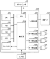
図1は、本実施形態における記録装置100と、記録装置100に接続されたホストコンピュータ(ホスト装置)10と、を備えた記録システムの概略構成を示す説明図である。ホストコンピュータ10は、記録装置100にて記録を行うべき記録データ、及び切断位置や記録媒体に関する情報などを、制御コマンドとしてプリンタケーブル11を介して記録装置100に出力する。
Hereinafter, embodiments of the present invention will be described in detail with reference to the drawings.
(First embodiment)
FIG. 1 is an explanatory diagram showing a schematic configuration of a recording system including a
本実施形態における記録装置100では、ロール状に巻いた連続紙を記録媒体103として用いる。記録媒体103は、帯状をなす長尺な台紙103Aと、この台紙103Aに長手方向に沿って、剥離可能に貼付けた複数のラベル103Bと、により構成されている。また、ロール状の記録媒体103は、記録装置100に設けられた媒体供給部102に保持されており、後述する搬送手段によって搬送方向(Y方向)に搬送される。なお、本実施形態における搬送手段は、記録媒体103を正搬送方向(Y1方向)だけでなく、正搬送方向とは逆方向である逆搬送方向(Y2方向)にも搬送可能となっている。記録媒体供給部102から正搬送方向(Y1方向)へと搬送された記録媒体103は、記録部110によって記録液が付与されて画像が記録された後、剥離部112によって記録済みのラベル103Bの一部分が台紙103Aから剥離される。
In the
記録媒体の搬送手段を構成する搬送ユニット104には、搬送モータ105、搬送ベルト106及び吸着ファン107が備えられている。搬送ベルト106は、ガイドローラ108A、108B、108C及び駆動ローラ108Dの間に架け渡されている。搬送モータ105の駆動力によって駆動ローラ108Dが回転することにより、搬送ベルト106が正搬送方向(Y1方向)もしくはその逆搬送方向(Y2方向)に移動する。吸着ファン107は図外のモータによって回転し、搬送ベルト106に形成された複数の吸着孔(不図示)から空気を吸引すると共に、吸引した空気を搬送ユニット104の、排出部としての排気口109から排出する。この吸着孔からの空気の吸引によって搬送ベルト106の表面(記録部110と対向する面)には記録媒体103が吸着される。これにより搬送ベルト106と共に記録媒体103は正搬送方向または逆搬送方向へと移動する。
A
記録部110には、記録手段としてインクジェット方式の記録ヘッド120が、搬送ベルト106の移動経路と対向する位置に着脱可能に搭載されている。記録ヘッド120は、搬送ベルト106によって搬送される記録媒体に向けて記録液(以下、インクともいう)を吐出可能とする複数の吐出口が形成されている。各吐出口には、記録ヘッド120の共通液室からインクが供給され、吐出口内に配置した吐出エネルギー発生素子の駆動により、吐出口からインクが吐出される。なお、記録ヘッド120において吐出口が形成されている面120aを吐出口面と称す。また、吐出エネルギー発生素子としては、電気熱変換素子(ヒータ)や電気機械変換素子(ピエゾ素子)などが知られている。電気熱変換素子は、電気エネルギーを受けて発熱し、その熱によって吐出口内のインクを発泡させ、その発泡時の圧力変化によって吐出口からインクを吐出させる。
An ink
記録ヘッド120の吐出口面120aには、搬送方向(Y方向)と交差する方向(本実施形態の場合、直交する方向(X方向))に沿って複数の吐出口が配置され、これら吐出口によって少なくとも一つの吐出口列が形成されている。本実施形態における記録ヘッド120は、フルラインタイプの記録ヘッドであり、使用する記録媒体103の幅に相当する長さの吐出口列が形成されている。
A plurality of discharge ports are arranged on the
記録動作に際して記録ヘッド120の吐出口は外気に露出した開放状態となっている。このとき、記録動作などによって一定時間内に吐出口からインク滴が吐出されている状況では、吐出口内のインクは頻繁にリフレッシュされることとなり、インクは吐出に適した状態に保たれる。一方、記録動作が開始された後、後述の後処理を実施すべく記録動作が停止された場合、開放状態にある吐出口から記録ヘッド120内の記録液の溶剤が蒸発し、記録液の増粘、固化などが生じて吐出口の吐出性能が低下することがある。
During the recording operation, the ejection port of the
そこで本実施形態では、記録ヘッド120内のインクの増粘、固化および吐出口面の損傷などを軽減するため、吐出口面120aの閉塞動作と開放動作とを選択的に実行可能な開閉機構としてのキャッピング機構(キャッピング手段)が設けられている。
Therefore, in the present embodiment, as an opening / closing mechanism capable of selectively executing the closing operation and the opening operation of the
本実施形態におけるキャッピング機構130は、記録ヘッド120を上下方向(Z方向)に移動させるヘッド移動機構140と、記録ヘッド120の吐出口面を覆うことが可能なキャッピング部材151を移動させるキャップ移動機構150とを備える。ヘッド移動機構140は、記録ヘッド120を備えた記録部110の側面に設けたラック141と、ラック141に噛合するピニオンギア142と、ピニオンギア142を回転させるヘッドモータ143と、を備える。本実施形態ではヘッドモータ143を駆動してピニオンギア142を回転させることにより、ラック141の設けられた記録部110と共に記録ヘッド120が上下方向(Z方向)に移動する。
The
キャップ移動機構150は、キャッピング部材151と、キャッピング部材151の一部に設けられたラック152と、ラック152に噛合するピニオンギア153と、ピニオンギア153を回転させるキャップモータ154と、を備える。本実施形態では、キャップモータ154を駆動してピニオンギア153を回転させることにより、これに噛合するラック152と共にキャッピング部材151が、Z方向と交差する方向(本実施形態では、Y方向)に沿って移動する。
The
このヘッド移動機構140とキャップ移動機構150とを所定の手順で動作させることにより、吐出口面120aをキャッピング部材151によって閉塞状態あるいは開放状態にすることができる。図1は記録ヘッド120aによって記録媒体103に記録を行っている状態、すなわちキャッピング部材151が吐出口面120aを開放する位置(退避位置)に保持されている状態を示している。ここで、記録ヘッド120の吐出口面120aを閉塞する閉塞動作を行う場合には、まず、ヘッドモータ143の駆動によって記録ヘッド120を、キャッピング部材151より上方へと移動させる。この後、キャップモータ154を駆動してキャッピング部材151をY1方向へと移動させ、吐出口面120aと所定の間隙を介して対向させる。この後、記録ヘッド120をヘッドモータ143の駆動によって下降させ、記録ヘッド120とキャッピング部材151とを接触させる。これにより、吐出口面120aはキャッピング部材151に閉塞され、外気との連通は遮断される。なお、以上説明した手順とは逆の手順でヘッド移動機構140とキャップ移動機構150とを作動させることにより、吐出口面120aを閉塞状態から開放状態へと切り替えられる。以下、この閉塞状態から開放状態への切換え動作を開放動作と称す。なお、開放動作が完了した開放完了状態になった際には、記録ヘッド120は、記録位置に搬送されたラベル103Bに対して記録可能な状態になっているものとする。本発明において、開放完了状態とは、記録ヘッド120によりラベル103Bに対して記録可能な記録可能状態である。
By operating the
また、記録装置100には記録媒体103に対する記録タイミングを定めるために記録媒体の各ラベルの先端位置を検出する先端検知センサ111が設けられている。この先端検出センサ111は、正搬送方向(Y1方向)に搬送される記録紙103の台紙103Aに貼り付けられた複数のラベル103Bそれぞれの先端を、記録ヘッド120によるラベル103Bに対する記録位置よりY1方向における上流位置で検出する。先端検知センサ111は、例えば、反射型センサ、透過型センサのいずれかまたは双方を備え、台紙とラベルとは透過率に差があることから受光量を検出することによって先端を検出することができる。また、記録媒体103のラベル103Bに先端検出用のマークが形成されている場合、マークと他の部分とで反射率に差があることから受光量を検出することによって記録媒体の先端を検出することもできる。また、搬送ユニット104に設けられたガイドローラ108Aの回転軸には、その回転軸に同期して回転する周知のロータリエンコーダが備えられ、先端検知センサ111とともに、記録媒体103の搬送位置を検出する搬送位置検出手段として機能する。
Further, the
Y1方向における、記録ヘッド120によるラベル103Bに対する記録位置の下流側には、記録部110で記録された記録済みのラベル103Bを台紙103Aから剥離させるための剥離部112が設けられている。この剥離部は、本発明における、所定の後処理が実行される後処理部である。この剥離部112は、搬送手段ユニット104によって正搬送方向(Y1方向)に搬送されてきた記録媒体103を、記録済みのラベル103Bと台紙103Aとを異なる方向へと導くことにより、記録済みのラベル103Bを剥離位置に位置させて台紙103Aから剥離させる。このとき、ラベル103Bは、一部分が台紙103Aから剥離され、他の部分が台紙103Aに付いている状態になっている。ラベル検知センサ113は、剥離されたラベル103Bが作業者によって剥離部112から取り出されたことを検出する。ラベルの取り出しが検出されると、搬送ユニット104によって連続紙103を記録開始位置まで正搬送方向(Y1方向)とは逆方向である逆搬送方向(Y2方向)に搬送した後、次の記録対象となるラベル(例えば、取り出されたラベルに最も近くに位置していたラベル)に対して記録を行う。なお、記録開始位置とは、記録対象となるラベルの先端が、先端検知センサ111よりもY1方向において上流側に位置するよう定められた位置である。なお、検出対象となるラベルは、本実施形態では取り出されたラベルの次のラベルとしている。但し、記録装置100の記録部110から剥離部に至る搬送経路の長さ、あるいは使用するラベルのY方向における長さによっては、取り出されたラベルの次のラベルよりさらにY1方向において上流側に位置する他のラベルが記録対象となる場合もある。
In the Y1 direction, a
図2は、本実施形態における記録装置100の制御系の概略構成を示すブロック図である。制御系200は、制御部としての中央処理装置(CPU)201を備える。CPU201は、不揮発性メモリ(ROM)202に格納されている制御プログラムを実行し、各周辺装置を制御する制御部として機能する。また、CPU201は、各種データ処理のワークエリアや受信バッファとして使用されるRAM203や、記録すべき画像の記録データを展開する展開部としてイメージメモリ204と接続されている。CPU201は、後述する取得時間Tや、後述する予測時間Tcなど記憶するメモリ206と接続されている。さらにCPU201は、記録ヘッド120を駆動するヘッド駆動回路205や、記録装置100に設けられた各種モータに対応したモータ駆動回路が接続されている。図2では前述の搬送モータ105、ヘッドモータ143およびキャップモータ154などのモータ駆動回路105Y、143Y及び154aを示しているが、記録装置100に設けられたモータのモータ駆動回路もCPU201によって制御される。モータとしては、記録装置記録ヘッドのクリーニング動作、記録動作、及び記録媒体の切断動作などを行うための駆動力を発する各種モータが設けられており、各々のモータ駆動回路もCPU201によって制御される。さらにCPU201は、記録媒体103の検知、装置内の各部の動作状態の検知などを行うセンサ群208が接続されている。このセンサ群208には、前述の先端検知センサ111、ラベル検知センサ113、およびロータリエンコーダなども含まれる。
FIG. 2 is a block diagram illustrating a schematic configuration of a control system of the
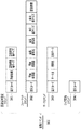
図3は、本実施形態の記録システムにおいて送信される各種コマンドを示す図である。ここに示す各種コマンドは、本実施形態のホストコンピュータ10からプリンタケーブル11を介して記録装置100に送信される。図3において、300は記録コマンドを示している。この記録コマンド300は、記録媒体の種類およびサイズ等を通知する記録媒体設定コマンド301、記録領域等を指定するフォーマットコマンド302、記録画像の記録データに関する情報を通知するデータコマンド303、ジョブ開始コマンド304などを含む。記録装置100は、ホストコンピュータ10から送信されてきた記録コマンド300に基づいて記録動作を行う。
FIG. 3 is a diagram showing various commands transmitted in the recording system of the present embodiment. Various commands shown here are transmitted from the
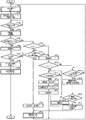
図4は本実施形態における全体的な制御動作を示すフローチャートである。なお、この図4に示す判定処理および制御処理は、CPU201によって実行される。
S401では、記録部110でのラベル103Bに対する記録動作が終了してから、CPU201は、その記録済みのラベル103Bが剥離部112にて台紙103Aから剥離され、作業者によって取り出されるまでの予測の経過時間の設定を行う。この予測設定によって設定された経過時間を予測時間Tcとして定める。予測時間Tcの設定方法は図5に基づいて後に説明する。
FIG. 4 is a flowchart showing an overall control operation in this embodiment. Note that the determination process and the control process shown in FIG.
In step S401, after the recording operation on the
S402では、CPU201は、記録ヘッド120の吐出口面120aがキャッピング部材151によって閉塞されていれば開放動作を実行させて、開放されていればそのままの状態で、搬送ユニット104によって記録媒体103を正搬送方向(Y1方向)に搬送することによって記録開始位置に位置していたラベルを記録位置に搬送しつつ、記録位置に搬送されるラベル103Bに対して記録部110からインクを吐出し、画像の記録を開始する。S403では、CPU201は、前記ラベル103Bへの記録動作が終了する記録終了位置まで記録媒体103が搬送されたか否かを判断する。
S404では、CPU201は、記録位置にあるラベル103Bへの記録動作が終了した時点から、記録済みのラベル103が剥離部112で台紙103Aから剥離され、作業者によって装置外へと取り出されるまでの経過時間である取得時間Tの計測を開始する。なお、この取得時間Tは、前述のS401において算出された予測時間Tcとは異なり、ラベルに対する記録動作終了時から装置外へ取り出されるまでの経過時間を実際に計測して得た計測時間を意味する。この後、S405では、CPU201は、次に記録を行うべき記録データの有無(RAM203に次に記録を行うべきで記録データが有るか無いか)を判定する。ここで、CPU201は、次に行うべき記録データが無いと判定した場合(S405のNO)、S406に移行し記録ヘッド120の吐出口面120aをキャッピング機構130のキャッピング部材151によって閉塞する前述の閉塞動作を行う。
In step S <b> 402, the
In S404, the
S407では、CPU201は、剥離部112へ送られて台紙103Aから剥離されたラベル103が、作業者によって取り出されてラベル無し状態になったか否かをラベル検出センサ113からの検出信号に基づいて判断する。CPU201は、ラベル無し状態になったと判断すると(S407のYES)、S408では前述のS404で開始したラベル取得時間Tの計測動作を終了し、計測開始から計測終了までの経過時間を取得時間Tとして設定し、取得時間Tを、S402における記録動作(最後に実施した記録動作)が何枚目であるかということと対応づけてメモリ206に記憶させる。S409では、CPU201は、記録媒体103を逆搬送方向(Y2方向)に搬送させ、次に記録を行うべきラベル103Bを前述の記録開始位置へ移動させ、次の記録データの受信を待つ。
In step S <b> 407, the
一方、S405において、CPU201は、次に記録を行うべき記録データがあると判断した場合(S405のYES)には、S408における閉塞動作を実施せず、S410へと移行する。S410では、CPU201は、前述の予測時間Tc(メモリ206に記憶された、S402における記録動作(最後に実施した記録動作)と対応した予測時間Tc)が後述する開放可能時間T1以下であるか否かを判断する。予測時間Tcが開放可能時間T1以下である場合には、CPU201は、記録ヘッド120の吐出口を開放状態に保ちつつ、剥離部112で剥離されたラベル103Bが作業者によって取り出されるのを待つ。ここで開放可能時間とは、記録ヘッド120による記録品質の低下を生じさせることなく吐出口面120aを継続的に開放させておくことが可能な時間の最大値(最大開放時間)から、前述の閉塞動作に要する時間と所定のマージンに対応する時間と、を差し引いた時間である。なお、開放可能時間は、所定のマージンに対応する時間を差し引かないものであってもよい。
On the other hand, if the
S411では、CPU201は、ラベル103Bへの記録動作が終了した時点から、ラベル検知センサ113によるラベル無しが検知されるまでの経過時間が開放可能時間以下(T1以下)であるか否かを判断する。ラベル検知センサ113が開放可能時間T1以内にラベル無しを検知した場合、CPU201は、S412において、前述のS404で開始された取得時間Tの計測を終了した後、計測開始から計測終了までの経過時間を取得時間Tとして設定し、取得時間Tを、S402における記録動作(最後に実施した記録動作)が何枚目であるかということと対応づけてメモリ206に記憶させる。この後、CPU201は、S414において、次のラベル103Bの記録を行うために、記録媒体103を逆搬送方向Y2へと搬送する、いわゆるバックフィードを行い、再びS401へと移行する。
In S411, the
CPU201は、S410において、予測時間Tcが開放可能時間T1より長いと判断した場合(S410のNO)、あるいはS411で開放可能時間T1以内にラベル検知センサ113がラベル無しを検知しなかった場合(S411のNO)にはS415へ移行する。CPU201は、S415において、記録ヘッド120の吐出口面120aをキャッピング部材によって覆う閉塞動作を実行し、インクの増粘、固化を抑制すると共に吐出口面120aを保護する。またCPU201は、S416において、ラベル無しが検知された時点でS417へと移行し、S404で開始されていた取得時間Tの計測を終了させる。この後、CPU201は、S418において、記録媒体103を記録開始位置へ搬送するバックフィードを行う。そして、CPU201は、S419において、記録ヘッド120の吐出口面120aの開放動作を行い記録可能な状態とする。
If the
なお、本実施形態において、CPU201は、あるラベルについての記録動作終了後、次に記録を行うべき記録データがあり、予測時間TcがT1以下であれば、キャッピング部材151による閉塞動作を実施しないようにしているが、本発明はこれに限らない。あるラベルについての記録動作終了後、次に記録を行うべき記録データがあった場合でも、CPU201がキャッピング151による閉塞動作を実施させるようにしてもよい。
In this embodiment, the
図5は、本実施形態で実施される予測時間Tcの算出処理を示すフローチャートである。図5に示すフローチャートはCPU201により実行される。
FIG. 5 is a flowchart showing the calculation process of the predicted time Tc implemented in this embodiment. The flowchart shown in FIG. 5 is executed by the
CPU201は、S501において、メモリ206に記憶されている情報に基づいて、過去にN回以上の記録動作(N枚を超えるラベルに対する記録動作)を実行しているか否かの判断を行う。CPU201は、過去にN回(N枚)以上の記録動作をしていないと判断した場合、S502において、予め定めた初期値を予測時間Tcとして設定し、この予測時間Tcを、これから実施する記録動作が何回目(何枚目)であるかということと対応づけてメモリ206に記憶させる。また、CPU201は、N≧1であり、1枚以上のラベルが記録されていると判断した場合は、前回以前のラベル記録動作における取得時間を予測時間Tcの設定に用いる。CPU201は、S501において、過去にN枚以上のラベル103Bに対して記録動作が行われている場合、これから実行する記録動作に対して直前に実行したN回の記録動作における取得時間Tの中央値を、予測時間Tcとして設定し、この予測時間Tcを、これから実施する記録動作が何回目(何枚目)であるかということと対応づけてメモリ206に記憶させる。
In step S <b> 501, the
図6および図7は、それぞれ、ラベル取得時間Tから予測時間Tcを算出した結果を示す図である。各図中、(a)は、メモリ206に記憶された情報であり、過去のラベル記録枚数と取得時間Tおよび取得時間の中央値とが対応づけられてメモリ206に記憶されていることを示す表であり、(b)は過去のラベル記録枚数、取得時間T、取得時間の中央値を示すグラフであり、(a)と(b)とは互いに対応している。
6 and 7 are diagrams showing the results of calculating the predicted time Tc from the label acquisition time T, respectively. In each figure, (a) is information stored in the
図6および図7では、例として、N=3、初期値=5秒、開放可能時間T1=4秒で、14枚のラベルの記録を行った場合を示す。また、記録ヘッドの吐出口面を開放状態から閉塞状態へと切り替える閉塞動作に要する時間と、吐出口面を閉塞状態から開放状態へと切り替える開放動作に要する時間と、を合わせた時間(閉塞・開放時間)は5秒とする。 6 and 7 show an example in which 14 labels are recorded with N = 3, an initial value = 5 seconds, and an openable time T1 = 4 seconds. In addition, the time required for the closing operation for switching the discharge port surface of the recording head from the open state to the closed state and the time required for the opening operation for switching the discharge port surface from the closed state to the open state are combined. The opening time is 5 seconds.
図6に示す例の場合、14枚目の記録動作の前に設定される予測時間Tcは、図5のフローのように、直前実行した11回目、12回目及び13回目の中央値(最長時間が25.6秒であり最短時間2.8秒がであるから中央値は3.1秒となる)から予測時間Tc=3.1であり、開放可能時間T1(=4秒)と予測時間Tcとの関係は、T1≧Tcである。なお、(N+1)枚目以降のラベルについては、6、12枚目のラベルを除き、キャッピング部材151による閉塞・開放動作がラベルへの記録動作後に行われない。このため、本実施形態の制御動作によって閉塞・開放動作を行った場合と、ラベル毎に閉塞・開放動作を行った場合とを比較すると、記録動作全体の所要時間が短縮される。
In the case of the example shown in FIG. 6, the predicted time Tc set before the recording operation of the 14th sheet is the median value (longest time) of the 11th, 12th and 13th times executed immediately before, as in the flow of FIG. Is 25.6 seconds and the shortest time is 2.8 seconds, so the median is 3.1 seconds) to the predicted time Tc = 3.1, the openable time T1 (= 4 seconds) and the predicted time The relationship with Tc is T1 ≧ Tc. For the (N + 1) th and subsequent labels, except for the sixth and twelfth labels, the closing / opening operation by the capping
また、図7に示す例の場合、14枚目の記録動作の前に設定される予測時間Tcは、中央値から求められる予測時間Tc=12.2秒であり、開放可能時間T1(4秒)と予測時間Tcとの関係は、T1<Tcとなる。このため、ラベルの記録動作が終了するとすぐにキャッピング部材による閉塞動作が行われる。 In the case of the example shown in FIG. 7, the predicted time Tc set before the recording operation of the 14th sheet is the predicted time Tc calculated from the median value = 12.2 seconds, and the openable time T1 (4 seconds). ) And the predicted time Tc is T1 <Tc. For this reason, the closing operation by the capping member is performed as soon as the label recording operation is completed.
すなわち、予測時間Tcが開放可能時間T1以下の場合、本実施形態の制御動作を実施することで、記録品質の低下を防止しながら、次のラベルを記録するまでにかかる時間を短縮し、生産性の低下を最小限に抑えることができる。 That is, when the predicted time Tc is equal to or shorter than the openable time T1, the control operation according to the present embodiment is performed to reduce the time required to record the next label while preventing the recording quality from being lowered. The decrease in sex can be minimized.
なお、図5ないし図7では、予測時間Tcの設定に中央値を用いた例を示したが、予測時間Tcは平均値を用いる方法やその他の方法によって算出することも可能であり、予測時間の算出方法は任意に設定可能である。また、予測時間Tcの算出に用いるサンプリング数Nは1以上の自然数とし、取得時間の変動などを勘案して適宜設定可能である。 5 to 7 show an example in which the median value is used for setting the predicted time Tc. However, the predicted time Tc can also be calculated by a method using an average value or other methods. The calculation method can be arbitrarily set. The sampling number N used for calculating the predicted time Tc is a natural number of 1 or more, and can be set as appropriate in consideration of fluctuations in acquisition time.
(第2の実施形態)
次に、本発明の第2の実施形態を説明する。以下の説明では、上記第1の実施形態と第2の実施形態との相違点について述べる。なお、この第2の実施形態においても、第1の実施形態と同様に、図1および図2に示す構成を有するものとする。
第1の実施形態では、CPU201は、閉塞動作を行うか否かを判定した。これに対し、この第2の実施形態では、CPU201は、記録ヘッド120に対する閉塞動作を実行させた後、剥離部112からラベルが取り出されたことをラベル検知手段113が検知する前に、予測時間Tcに応じて、吐出口面120aに対する開放動作を先行して開始させる。なおこの第2の実施形態では、CPU201は、キャッピング機構130によって記録ヘッドの吐出口面120aを閉塞状態から開放状態へと切り替える動作と次に記録すべきラベルを逆搬送する動作とを並行に動作させる。CPU201は、記録ヘッド120によるラベルに対する記録動作を終了させた後、ラベル検知センサ113によってラベル無しが検出されてからすぐに次に記録すべきラベルが記録開始位置に達するまで記録媒体を逆搬送させる。また、キャッピング機構130によって記録ヘッドの吐出口面120aを閉塞状態から開放が完了した状態へと切り替えるために要する時間が、ラベル無しが検出されてから次に記録すべきラベルを記録開始位置に達するまで記録媒体を逆搬送する時間より長いことを前提とする。
(Second Embodiment)
Next, a second embodiment of the present invention will be described. In the following description, differences between the first embodiment and the second embodiment will be described. Note that the second embodiment also has the configuration shown in FIGS. 1 and 2 as in the first embodiment.
In the first embodiment, the
図8は、本発明の第2の実施形態における全体的な制御動作を示すフローチャートである。図8に示すフローチャートはCPU201により実行される。図8に示すS701〜715、717、723、724、725に示す処理は、それぞれ第1の実施形態におけるS401〜415、416、417、418、419と同様であるため、説明を省略する。
FIG. 8 is a flowchart showing an overall control operation in the second embodiment of the present invention. The flowchart shown in FIG. 8 is executed by the
CPU201は、ステップS710において、予測時間Tc(メモリ206に記憶された、S702における記録動作(最後に実施した記録動作)と対応した予測時間Tc)が開放可能時間T1より長いと判断した場合(S710のNO)にはS715へと移行し、キャッピング機構130によって吐出口面120aを閉塞状態とする。次にCPU201は、S716において、予測時間Tcが記録準備時間を超える(T2を超える)かどうかを判断する。なお、記録準備時間T2とは、記録ヘッドの吐出口面を開放完了状態から閉塞状態へと切り替える閉塞動作に要する時間と、吐出口面を閉塞状態から開放完了状態へと切り替える開放動作に要する時間と、所定のマージンに対応した時間と、を合わせた時間である。記録準備時間T2は、所定のマージンに対応する時間を合わせないものであってもよい。
If the
CPU201は、予測時間Tcが記録準備時間T2より長い場合(S716のYES)、S718に移行し、ラベル103Bに対する記録動作終了から、(予測時間Tc−記録準備時間T2)の時間が経過したか否かを判断する。CPU201は、S719において、記録動作終了から(Tc−T2)の時間が経過した時点で、記録キャッピング機構130による開放動作、すなわち記録ヘッド120よって記録が可能となる記録準備動作を、予想されるラベルの取り出し動作に先行して開始させるとともに、開放時間T4の計測を開始する。次にCPU201は、S720おいて、S719における開放時間T4の計測の開始から開放可能時間T1以内にラベル無しがラベル検知センサ113によって検知されたか否かを判断する。ここで、CPU201は、開放可能時間T1以内にラベル無しが検知された場合には、S721において、開放時間T4の計測を終了させるとともに、S704で開始された取得時間Tの計測を終了した後、計測開始から計測終了までの経過時間を取得時間Tとして設定し、取得時間Tを、S702における記録動作(最後に実施した記録動作)が何枚目であるかということと対応づけてメモリ206に記憶させる。そして、CPU201は、S714において記録媒体103のバックフィードを行ない、次に記録すべきラベルを記録開始位置へと移動させる。この後、CPU201は、S701へと移行して予測時間を設定し、記録位置にあるラベルへの記録動作を開始する。また、CPU201は、S720において、T1時間以内にラベル無しが検知されなかった場合には、S722へと移行して開放時間T4の計測を終了させるとともに、キャッピング機構130により閉塞動作を行なう。この後、CPU201は、S717へと移行し、ここでラベル無しが検知されたと判断された場合には、先に説明したS712〜S714,S723、S701の処理を実行し、S702で記録位置にあるラベルへの記録を行う。
When the predicted time Tc is longer than the recording preparation time T2 (YES in S716), the
以上のようにこの第2の実施形態では、キャッピング機構130の開放動作に要する時間が、記録媒体103のバックフィードに要する時間よりも長い場合に、予測時間Tcに合わせてキャッピング機構130の記録準備動作(開放動作)を先行して行なう。これにより、記録ヘッド内のインクの増粘、固化などに起因する記録品質の低下を軽減しながら、次のラベルを記録するまでにかかる時間を短縮することができ、生産性の低下を抑えることができる。
As described above, in the second embodiment, when the time required for the opening operation of the
(他の実施形態)
上記第1、第2の実施形態では、台紙にラベルを貼り付けた記録媒体を用いる記録装置を例にとり説明したが、本発明は、上記各実施形態に用いられる記録媒体以外の記録媒体に対して記録動作を行なう記録装置にも適用可能である。
また、本発明は、上記第1、第2の実施形態のように記録済みのラベル103Bを台紙103Aから剥離させる剥離動作を後処理として行なう記録装置に限定されない。すなわち、本発明は記録動作を停止して後処理を実施するものであれば、後処理の形態は上記各実施形態に示したものに限定されない。例えば、排出部に排出された、連続紙からなる記録媒体を、所定の長さ毎に切断する切断処理を作業者が後処理として実行する記録装置においては、後処理実施中の記録動作は停止させるため、本発明を適用すれば、後処理動作中のインクの劣化による記録品質の低下を軽減することができる。この場合、排出部が、後処理が実行される部位となる。このため、排出部が本発明の後処理部に対応する。
(Other embodiments)
In the first and second embodiments, the recording apparatus using the recording medium with the label attached to the mount has been described as an example. However, the present invention is applicable to recording media other than the recording medium used in the above embodiments. The present invention can also be applied to a recording apparatus that performs a recording operation.
Further, the present invention is not limited to the recording apparatus that performs the peeling operation for peeling the recorded
また、上記各実施形態では、記録ヘッドの吐出口面に対し、閉塞、開放を行なうキャッピング機構を、記録ヘッドを移動させるヘッド移動機構と、キャップ部材を移動させるキャップ移動機構とにより構成した。このため、閉塞動作と開放動作の各々に要する時間は、ヘッドの移動時間とキャッピング部材の移動時間と合わせた時間となっている。これに対し、キャッピング機構を上記各実施形態とは異なる構成とすることも可能である。例えば、一定の位置に定められたキャッピング部材に対し、記録ヘッドのみを移動させて閉塞動作、開放動作を行なうようにすることも可能である。これによれば、閉塞動作、開放動作をそれぞれ単純化することができると共に、各動作の所要時間を短縮することが可能となる。 In each of the above embodiments, the capping mechanism that closes and opens the ejection port surface of the recording head includes the head moving mechanism that moves the recording head and the cap moving mechanism that moves the cap member. For this reason, the time required for each of the closing operation and the opening operation is a time combined with the moving time of the head and the moving time of the capping member. On the other hand, the capping mechanism may be configured differently from the above embodiments. For example, it is also possible to perform the closing operation and the opening operation by moving only the recording head with respect to the capping member set at a certain position. According to this, the closing operation and the opening operation can be simplified, and the time required for each operation can be shortened.
また、上記各実施形態では、記録媒体を連続的に搬送しつつフルラインタイプのインクジェット記録ヘッドを用いて記録を行なう記録装置を例に取り説明した。しかしながら、本発明は、上記のような形態の記録装置に限らず、他の形態の記録装置にも適用可能である。すなわち、記録媒体を搬送方向に沿って間欠的に搬送すると共に、記録媒体停止時に記録ヘッドを搬送方向と直交する方向に沿って移動させながら記録液を吐出して記録動作を行なうシリアル型の記録装置にも本発明は適用可能である。 In each of the above embodiments, a recording apparatus that performs recording using a full-line type inkjet recording head while continuously conveying a recording medium has been described as an example. However, the present invention is not limited to the recording apparatus having the above-described form, but can be applied to other forms of recording apparatuses. That is, a serial type recording in which the recording medium is intermittently transported along the transport direction and the recording head is ejected while moving the recording head along the direction orthogonal to the transport direction when the recording medium is stopped. The present invention can also be applied to an apparatus.
さらに、本発明は、連続紙に記録を行なう記録装置に限らず、カットシートに順次記録を行なう記録装置にも適用可能である。 Furthermore, the present invention is not limited to a recording apparatus that records on continuous paper, but can also be applied to a recording apparatus that sequentially records on cut sheets.
100 記録装置
103 記録媒体(連続紙)
103A 台紙
103B ラベル
104 搬送ユニット
110 記録部
120 記録ヘッド
112 剥離部
200 制御部
100
Claims (15)
前記吐出口を覆う開閉手段と、
前記記録手段による記録済みの記録媒体を所定の後処理が行われる後処理部へ搬送する搬送手段と、
前記搬送手段により前記後処理部に搬送された前記記録済みの記録媒体が前記後処理部に停止する状態になることに応答して前記開閉手段を閉状態とし、操作者による前記記録済みの記録媒体を前記後処理部から取り外す操作に応答して前記開閉手段を開状態とする制御手段と、
を有することを特徴とする記録装置。 Recording means for discharging the recording liquid from the discharge port and recording on a recording medium;
Opening and closing means for covering the discharge port;
Transport means for transporting a recording medium recorded by the recording means to a post-processing section where predetermined post-processing is performed;
In response to the recorded recording medium transported to the post-processing unit by the transport unit being stopped by the post-processing unit, the open / close unit is closed, and the recorded recording by an operator is performed. Control means for opening the opening and closing means in response to an operation of removing the medium from the post-processing unit ;
A recording apparatus comprising:
前記制御手段は、前記予測手段による予測時間に従って前記開閉手段を制御することを特徴とする請求項1または2に記載の記録装置。 A prediction means for predicting a time from when the recording operation by the recording means is completed until the next recording operation is possible;
The recording apparatus according to claim 1, wherein the control unit controls the opening / closing unit in accordance with a prediction time by the prediction unit.
前記予測時間が、前記記録手段の吐出口を継続的に開状態とさせておくことが可能な時間の最大値である最大開放時間から前記閉状態とするのに要する時間を差し引いた開放可能時間以下である場合には、前記開放可能時間において前記開閉手段による閉塞動作および開放動作を実行させず、
前記予測時間が前記開放可能時間より長い場合には、記録動作終了後に前記閉塞動作を行なう一方、次の記録動作の前に前記開放動作を行なうことを特徴とする請求項3ないし7のいずれか一項に記載の記録装置。 The control means includes
Opening time obtained by subtracting the time required for the predicted state from the maximum opening time, which is the maximum value of the time during which the discharge port of the recording unit can be continuously opened, from the maximum opening time. If it is below, do not perform the closing operation and the opening operation by the opening and closing means in the openable time,
8. The opening operation is performed before the next recording operation while the closing operation is performed after the recording operation is completed when the predicted time is longer than the possible opening time. The recording device according to one item.
記録装置。 9. The transport apparatus according to claim 3, further comprising transport means capable of transporting the recording medium in a forward transport direction and a reverse transport direction opposite to the forward transport direction. Recording device.
前記予測時間が前記記録準備時間以上であり、かつ前記次の記録動作を開始させるために前記記録媒体を前記逆搬送方向へと搬送する時間より前記開放動作に要する時間の方が長い場合に、
記録動作終了後に前記閉塞動作を行う一方、
記録動作終了後に前記記録準備時間が経過した時点から前記開放動作を行なう、ことを特徴とする請求項9に記載の記録装置。 The control means compares the estimated preparation time with a recording preparation time that combines the time required for the closing operation by the opening / closing means and the time required for the opening operation,
When the estimated time is equal to or longer than the recording preparation time, and the time required for the opening operation is longer than the time for transporting the recording medium in the reverse transport direction to start the next recording operation,
While performing the closing operation after the recording operation ends,
The recording apparatus according to claim 9, wherein the release operation is performed after the recording preparation time has elapsed after the recording operation is completed.
前記搬送手段は、前記記録媒体を搬送しつつ、前記記録手段によって記録された前記ラベルを前記台紙から剥離させる剥離手段と、
前記剥離手段によって剥離されたラベルが装置外へと取り出されたことを検知するラベル検知手段と、を備えることを特徴とする請求項3ないし10のいずれか一項に記載の記録装置。 The recording medium is composed of a mount made of continuous paper and a label attached to the mount so as to be peelable,
The conveying means is a peeling means for peeling the label recorded by the recording means from the mount while conveying the recording medium;
The recording apparatus according to claim 3, further comprising: a label detection unit that detects that the label peeled off by the peeling unit is taken out of the apparatus.
前記記録工程による記録済みの記録媒体を所定の後処理が行われる後処理部へ搬送する搬送工程と、
前記搬送工程により前記後処理部に搬送された前記記録済みの記録媒体が前記後処理部に停止する状態になることに応答して、前記吐出口を閉状態とする工程と、
操作者による前記記録済みの記録媒体を前記後処理部から取り外す操作に応答して前記吐出口を開状態とする工程と、
を有することを特徴とする記録方法。 A recording step of discharging recording liquid from the discharge port and recording on a recording medium;
A transporting step of transporting the recording medium recorded by the recording step to a post-processing unit where a predetermined post-processing is performed;
In response to the recording medium that has been transported to the post-processing unit being transported by the transporting process being stopped by the post-processing unit, closing the ejection port;
A step of opening the discharge port in response to an operation of removing the recorded recording medium from the post-processing unit by an operator;
A recording method characterized by comprising:
前記吐出口を覆う開閉手段と、
前記記録手段による記録済みの記録媒体を所定の後処理が行われる後処理部へ搬送する搬送手段と、
前記記録手段による記録動作が終了してから次の記録動作が可能になるまでの時間を予測する予測手段と、
前記搬送手段により前記後処理部に搬送された前記記録済みの記録媒体が前記後処理部に停止する状態になることに応答して、前記予測手段による予測時間に従って前記開閉手段を閉状態とする制御手段と、
を有することを特徴とする記録装置。 Recording means for discharging the recording liquid from the discharge port and recording on a recording medium;
Opening and closing means for covering the discharge port;
Transport means for transporting a recording medium recorded by the recording means to a post-processing section where predetermined post-processing is performed;
A predicting means for predicting a time from the end of the recording operation by the recording means until the next recording operation becomes possible;
In response to the recorded recording medium transported to the post-processing unit by the transport unit being stopped by the post-processing unit, the opening / closing unit is closed according to the time predicted by the prediction unit. Control means;
A recording apparatus comprising:
前記吐出口を覆う開閉手段と、
前記記録手段による記録済みの台紙に貼り付けられたラベルを前記台紙から一部が剥離した状態とする後処理部へ搬送する搬送手段と、
前記搬送手段により前記後処理部に搬送された前記記録済みのラベルの一部が前記台紙から剥離して前記後処理部に停止する状態になることに応答して前記開閉手段を閉状態とする制御手段と、
を有することを特徴とする記録装置。 Recording means for discharging recording liquid from the discharge port and recording on a plurality of labels attached to the mount so as to be peelable,
Opening and closing means for covering the discharge port;
A transport unit that transports a label attached to a mount that has been recorded by the recording unit to a post-processing unit that is partially peeled from the mount ; and
The opening / closing means is closed in response to a state in which a part of the recorded label conveyed to the post-processing section by the transport means is peeled off from the mount and stops at the post-processing section. Control means;
A recording apparatus comprising:
Priority Applications (3)
| Application Number | Priority Date | Filing Date | Title |
|---|---|---|---|
| JP2014064375A JP6267030B2 (en) | 2014-03-26 | 2014-03-26 | Recording apparatus and recording method |
| US14/668,188 US9908341B2 (en) | 2014-03-26 | 2015-03-25 | Printing apparatus and printing method |
| EP15160824.7A EP2939835B1 (en) | 2014-03-26 | 2015-03-25 | Printing apparatus and printing method |
Applications Claiming Priority (1)
| Application Number | Priority Date | Filing Date | Title |
|---|---|---|---|
| JP2014064375A JP6267030B2 (en) | 2014-03-26 | 2014-03-26 | Recording apparatus and recording method |
Publications (3)
| Publication Number | Publication Date |
|---|---|
| JP2015186846A JP2015186846A (en) | 2015-10-29 |
| JP2015186846A5 JP2015186846A5 (en) | 2016-03-31 |
| JP6267030B2 true JP6267030B2 (en) | 2018-01-24 |
Family
ID=52706095
Family Applications (1)
| Application Number | Title | Priority Date | Filing Date |
|---|---|---|---|
| JP2014064375A Active JP6267030B2 (en) | 2014-03-26 | 2014-03-26 | Recording apparatus and recording method |
Country Status (3)
| Country | Link |
|---|---|
| US (1) | US9908341B2 (en) |
| EP (1) | EP2939835B1 (en) |
| JP (1) | JP6267030B2 (en) |
Families Citing this family (4)
| Publication number | Priority date | Publication date | Assignee | Title |
|---|---|---|---|---|
| US9457925B1 (en) | 2015-04-21 | 2016-10-04 | Toshiba Tec Kabushiki Kaisha | Printing apparatus for controlling label mount rewind time, control method for controlling label mount rewind time and non-temporary recording medium |
| US10802463B1 (en) * | 2017-10-31 | 2020-10-13 | CMSI Technologies | Method of printing a tag and attaching the tag to a bag |
| US11814765B1 (en) * | 2019-04-23 | 2023-11-14 | CMSI Technologies | Method of printing a tag and attaching the tag to a bag |
| JP7455586B2 (en) | 2020-01-15 | 2024-03-26 | 東芝テック株式会社 | Label printer and label printer control program |
Family Cites Families (13)
| Publication number | Priority date | Publication date | Assignee | Title |
|---|---|---|---|---|
| JPH08323987A (en) | 1995-06-05 | 1996-12-10 | Citizen Watch Co Ltd | Nozzle capping method of ink-jet printing machine |
| JP3535837B2 (en) | 2000-07-21 | 2004-06-07 | キヤノン株式会社 | PRINTING APPARATUS, PRINTING SYSTEM, CONTROL METHOD, STORAGE MEDIUM, AND PROGRAM |
| JP4208640B2 (en) | 2002-06-04 | 2009-01-14 | キヤノン株式会社 | Printing system, printing control method, printing apparatus, and control method therefor |
| JP4307015B2 (en) | 2002-06-04 | 2009-08-05 | キヤノン株式会社 | Printing apparatus and control method thereof |
| JP4027161B2 (en) | 2002-06-04 | 2007-12-26 | キヤノン株式会社 | Printer apparatus and control method thereof |
| JP2004013349A (en) | 2002-06-04 | 2004-01-15 | Canon Inc | Imaging device, recording system, and recording control method thereof |
| JP4714622B2 (en) * | 2006-03-30 | 2011-06-29 | 富士フイルム株式会社 | Post-processing method and apparatus having post-processing apparatus for inkjet recording medium |
| JP4807203B2 (en) * | 2006-09-15 | 2011-11-02 | セイコーエプソン株式会社 | Double-sided recording apparatus and recording method |
| JP2010023498A (en) * | 2008-06-18 | 2010-02-04 | Canon Inc | Inkjet recorder and drying condition determination method of recorded image |
| JP5644056B2 (en) * | 2009-03-05 | 2014-12-24 | 株式会社リコー | Image forming apparatus and maintenance operation control program |
| JP5648540B2 (en) * | 2011-03-15 | 2015-01-07 | セイコーエプソン株式会社 | Printer control method and printer |
| JP2012192555A (en) | 2011-03-15 | 2012-10-11 | Seiko Epson Corp | Control method of printer and printer driver |
| JP5891602B2 (en) | 2011-04-28 | 2016-03-23 | 東洋製罐株式会社 | Inkjet printing apparatus and seamless can printing method using the same |
-
2014
- 2014-03-26 JP JP2014064375A patent/JP6267030B2/en active Active
-
2015
- 2015-03-25 EP EP15160824.7A patent/EP2939835B1/en active Active
- 2015-03-25 US US14/668,188 patent/US9908341B2/en active Active
Also Published As
| Publication number | Publication date |
|---|---|
| EP2939835A3 (en) | 2016-01-06 |
| EP2939835B1 (en) | 2021-05-05 |
| US9908341B2 (en) | 2018-03-06 |
| EP2939835A2 (en) | 2015-11-04 |
| US20150273882A1 (en) | 2015-10-01 |
| JP2015186846A (en) | 2015-10-29 |
Similar Documents
| Publication | Publication Date | Title |
|---|---|---|
| JP6267030B2 (en) | Recording apparatus and recording method | |
| JP7073564B2 (en) | Recording device and control method | |
| JP4906762B2 (en) | Printing apparatus and printing apparatus control method | |
| JP4807203B2 (en) | Double-sided recording apparatus and recording method | |
| US8882240B2 (en) | Inkjet printing apparatus and print head recovery method | |
| US8967890B2 (en) | Continuous sheet recording apparatus and method of controlling sorter in response to conveyance failure | |
| JP6713722B2 (en) | Image recording apparatus and image recording method | |
| EP2896505A2 (en) | Thermal printer | |
| JP5004539B2 (en) | Image recording apparatus, maintenance operation management method using the same, and program | |
| JP2010214876A (en) | Inkjet recorder | |
| JP5760911B2 (en) | Liquid ejection device | |
| JP2015147340A (en) | Printer and control method of the same | |
| JP2009233891A (en) | Inkjet recording apparatus and method | |
| JP6366945B2 (en) | Printing control apparatus, printing apparatus, inkjet printing apparatus, and printing method | |
| JP4658392B2 (en) | Inkjet recording device | |
| JP2011110801A (en) | Image recorder | |
| JP2011156680A (en) | Inkjet recording apparatus | |
| JP2021075011A (en) | Image recording device and image recording method | |
| JP2006076079A (en) | Inkjet printer | |
| JP2012035525A (en) | Inkjet image forming apparatus | |
| JP2015009388A (en) | Recording device and recording method | |
| JP5329182B2 (en) | Image recording apparatus and control method of image recording apparatus | |
| JP2010069837A (en) | Droplet jetting device, image formation device, and method of cleaning droplet jetting head | |
| JP2019093654A (en) | Inkjet recording device and wiping method of recording head | |
| JP2019098600A (en) | Ink jet recording apparatus and cleaning control method |
Legal Events
| Date | Code | Title | Description |
|---|---|---|---|
| A521 | Request for written amendment filed |
Free format text: JAPANESE INTERMEDIATE CODE: A523 Effective date: 20160215 |
|
| A621 | Written request for application examination |
Free format text: JAPANESE INTERMEDIATE CODE: A621 Effective date: 20160215 |
|
| A977 | Report on retrieval |
Free format text: JAPANESE INTERMEDIATE CODE: A971007 Effective date: 20161027 |
|
| A131 | Notification of reasons for refusal |
Free format text: JAPANESE INTERMEDIATE CODE: A131 Effective date: 20161108 |
|
| A521 | Request for written amendment filed |
Free format text: JAPANESE INTERMEDIATE CODE: A523 Effective date: 20161227 |
|
| A131 | Notification of reasons for refusal |
Free format text: JAPANESE INTERMEDIATE CODE: A131 Effective date: 20170530 |
|
| A521 | Request for written amendment filed |
Free format text: JAPANESE INTERMEDIATE CODE: A523 Effective date: 20170726 |
|
| TRDD | Decision of grant or rejection written | ||
| A01 | Written decision to grant a patent or to grant a registration (utility model) |
Free format text: JAPANESE INTERMEDIATE CODE: A01 Effective date: 20171205 |
|
| R150 | Certificate of patent or registration of utility model |
Ref document number: 6267030 Country of ref document: JP Free format text: JAPANESE INTERMEDIATE CODE: R150 |
|
| R250 | Receipt of annual fees |
Free format text: JAPANESE INTERMEDIATE CODE: R250 |
|
| R250 | Receipt of annual fees |
Free format text: JAPANESE INTERMEDIATE CODE: R250 |
|
| R250 | Receipt of annual fees |
Free format text: JAPANESE INTERMEDIATE CODE: R250 |