JP6263917B2 - Information processing apparatus, information processing method, and computer program - Google Patents
Information processing apparatus, information processing method, and computer program Download PDFInfo
- Publication number
- JP6263917B2 JP6263917B2 JP2013191634A JP2013191634A JP6263917B2 JP 6263917 B2 JP6263917 B2 JP 6263917B2 JP 2013191634 A JP2013191634 A JP 2013191634A JP 2013191634 A JP2013191634 A JP 2013191634A JP 6263917 B2 JP6263917 B2 JP 6263917B2
- Authority
- JP
- Japan
- Prior art keywords
- action
- data
- environment
- user
- projector
- Prior art date
- Legal status (The legal status is an assumption and is not a legal conclusion. Google has not performed a legal analysis and makes no representation as to the accuracy of the status listed.)
- Expired - Fee Related
Links
Images


Classifications
-
- G—PHYSICS
- G06—COMPUTING; CALCULATING OR COUNTING
- G06V—IMAGE OR VIDEO RECOGNITION OR UNDERSTANDING
- G06V40/00—Recognition of biometric, human-related or animal-related patterns in image or video data
- G06V40/20—Movements or behaviour, e.g. gesture recognition
-
- A—HUMAN NECESSITIES
- A63—SPORTS; GAMES; AMUSEMENTS
- A63F—CARD, BOARD, OR ROULETTE GAMES; INDOOR GAMES USING SMALL MOVING PLAYING BODIES; VIDEO GAMES; GAMES NOT OTHERWISE PROVIDED FOR
- A63F13/00—Video games, i.e. games using an electronically generated display having two or more dimensions
- A63F13/20—Input arrangements for video game devices
- A63F13/21—Input arrangements for video game devices characterised by their sensors, purposes or types
- A63F13/213—Input arrangements for video game devices characterised by their sensors, purposes or types comprising photodetecting means, e.g. cameras, photodiodes or infrared cells
-
- A—HUMAN NECESSITIES
- A63—SPORTS; GAMES; AMUSEMENTS
- A63F—CARD, BOARD, OR ROULETTE GAMES; INDOOR GAMES USING SMALL MOVING PLAYING BODIES; VIDEO GAMES; GAMES NOT OTHERWISE PROVIDED FOR
- A63F13/00—Video games, i.e. games using an electronically generated display having two or more dimensions
- A63F13/20—Input arrangements for video game devices
- A63F13/22—Setup operations, e.g. calibration, key configuration or button assignment
-
- A—HUMAN NECESSITIES
- A63—SPORTS; GAMES; AMUSEMENTS
- A63F—CARD, BOARD, OR ROULETTE GAMES; INDOOR GAMES USING SMALL MOVING PLAYING BODIES; VIDEO GAMES; GAMES NOT OTHERWISE PROVIDED FOR
- A63F13/00—Video games, i.e. games using an electronically generated display having two or more dimensions
- A63F13/25—Output arrangements for video game devices
-
- A—HUMAN NECESSITIES
- A63—SPORTS; GAMES; AMUSEMENTS
- A63F—CARD, BOARD, OR ROULETTE GAMES; INDOOR GAMES USING SMALL MOVING PLAYING BODIES; VIDEO GAMES; GAMES NOT OTHERWISE PROVIDED FOR
- A63F13/00—Video games, i.e. games using an electronically generated display having two or more dimensions
- A63F13/40—Processing input control signals of video game devices, e.g. signals generated by the player or derived from the environment
- A63F13/42—Processing input control signals of video game devices, e.g. signals generated by the player or derived from the environment by mapping the input signals into game commands, e.g. mapping the displacement of a stylus on a touch screen to the steering angle of a virtual vehicle
- A63F13/428—Processing input control signals of video game devices, e.g. signals generated by the player or derived from the environment by mapping the input signals into game commands, e.g. mapping the displacement of a stylus on a touch screen to the steering angle of a virtual vehicle involving motion or position input signals, e.g. signals representing the rotation of an input controller or a player's arm motions sensed by accelerometers or gyroscopes
-
- A—HUMAN NECESSITIES
- A63—SPORTS; GAMES; AMUSEMENTS
- A63F—CARD, BOARD, OR ROULETTE GAMES; INDOOR GAMES USING SMALL MOVING PLAYING BODIES; VIDEO GAMES; GAMES NOT OTHERWISE PROVIDED FOR
- A63F13/00—Video games, i.e. games using an electronically generated display having two or more dimensions
- A63F13/50—Controlling the output signals based on the game progress
- A63F13/53—Controlling the output signals based on the game progress involving additional visual information provided to the game scene, e.g. by overlay to simulate a head-up display [HUD] or displaying a laser sight in a shooting game
- A63F13/537—Controlling the output signals based on the game progress involving additional visual information provided to the game scene, e.g. by overlay to simulate a head-up display [HUD] or displaying a laser sight in a shooting game using indicators, e.g. showing the condition of a game character on screen
- A63F13/5375—Controlling the output signals based on the game progress involving additional visual information provided to the game scene, e.g. by overlay to simulate a head-up display [HUD] or displaying a laser sight in a shooting game using indicators, e.g. showing the condition of a game character on screen for graphically or textually suggesting an action, e.g. by displaying an arrow indicating a turn in a driving game
-
- A—HUMAN NECESSITIES
- A63—SPORTS; GAMES; AMUSEMENTS
- A63F—CARD, BOARD, OR ROULETTE GAMES; INDOOR GAMES USING SMALL MOVING PLAYING BODIES; VIDEO GAMES; GAMES NOT OTHERWISE PROVIDED FOR
- A63F13/00—Video games, i.e. games using an electronically generated display having two or more dimensions
- A63F13/60—Generating or modifying game content before or while executing the game program, e.g. authoring tools specially adapted for game development or game-integrated level editor
- A63F13/65—Generating or modifying game content before or while executing the game program, e.g. authoring tools specially adapted for game development or game-integrated level editor automatically by game devices or servers from real world data, e.g. measurement in live racing competition
-
- G—PHYSICS
- G06—COMPUTING; CALCULATING OR COUNTING
- G06F—ELECTRIC DIGITAL DATA PROCESSING
- G06F3/00—Input arrangements for transferring data to be processed into a form capable of being handled by the computer; Output arrangements for transferring data from processing unit to output unit, e.g. interface arrangements
- G06F3/01—Input arrangements or combined input and output arrangements for interaction between user and computer
- G06F3/011—Arrangements for interaction with the human body, e.g. for user immersion in virtual reality
-
- G—PHYSICS
- G06—COMPUTING; CALCULATING OR COUNTING
- G06F—ELECTRIC DIGITAL DATA PROCESSING
- G06F3/00—Input arrangements for transferring data to be processed into a form capable of being handled by the computer; Output arrangements for transferring data from processing unit to output unit, e.g. interface arrangements
- G06F3/01—Input arrangements or combined input and output arrangements for interaction between user and computer
- G06F3/017—Gesture based interaction, e.g. based on a set of recognized hand gestures
-
- G—PHYSICS
- G06—COMPUTING; CALCULATING OR COUNTING
- G06F—ELECTRIC DIGITAL DATA PROCESSING
- G06F3/00—Input arrangements for transferring data to be processed into a form capable of being handled by the computer; Output arrangements for transferring data from processing unit to output unit, e.g. interface arrangements
- G06F3/01—Input arrangements or combined input and output arrangements for interaction between user and computer
- G06F3/03—Arrangements for converting the position or the displacement of a member into a coded form
- G06F3/0304—Detection arrangements using opto-electronic means
-
- G—PHYSICS
- G06—COMPUTING; CALCULATING OR COUNTING
- G06N—COMPUTING ARRANGEMENTS BASED ON SPECIFIC COMPUTATIONAL MODELS
- G06N7/00—Computing arrangements based on specific mathematical models
- G06N7/01—Probabilistic graphical models, e.g. probabilistic networks
-
- G—PHYSICS
- G06—COMPUTING; CALCULATING OR COUNTING
- G06T—IMAGE DATA PROCESSING OR GENERATION, IN GENERAL
- G06T19/00—Manipulating 3D models or images for computer graphics
- G06T19/006—Mixed reality
-
- G—PHYSICS
- G06—COMPUTING; CALCULATING OR COUNTING
- G06V—IMAGE OR VIDEO RECOGNITION OR UNDERSTANDING
- G06V20/00—Scenes; Scene-specific elements
- G06V20/60—Type of objects
- G06V20/64—Three-dimensional objects
-
- G—PHYSICS
- G06—COMPUTING; CALCULATING OR COUNTING
- G06V—IMAGE OR VIDEO RECOGNITION OR UNDERSTANDING
- G06V40/00—Recognition of biometric, human-related or animal-related patterns in image or video data
- G06V40/20—Movements or behaviour, e.g. gesture recognition
- G06V40/23—Recognition of whole body movements, e.g. for sport training
-
- H—ELECTRICITY
- H04—ELECTRIC COMMUNICATION TECHNIQUE
- H04N—PICTORIAL COMMUNICATION, e.g. TELEVISION
- H04N13/00—Stereoscopic video systems; Multi-view video systems; Details thereof
- H04N13/30—Image reproducers
- H04N13/324—Colour aspects
-
- H—ELECTRICITY
- H04—ELECTRIC COMMUNICATION TECHNIQUE
- H04N—PICTORIAL COMMUNICATION, e.g. TELEVISION
- H04N13/00—Stereoscopic video systems; Multi-view video systems; Details thereof
- H04N13/30—Image reproducers
- H04N13/398—Synchronisation thereof; Control thereof
Description
本開示は、情報処理装置、情報処理方法及びコンピュータプログラムに関する。 The present disclosure relates to an information processing apparatus, an information processing method, and a computer program.
プロジェクタを利用して、仮想的な情報を現実世界の物体に重ね合わせて表示する、投影型拡張現実感システムと呼ばれる技術についての研究が進められている(例えば、特許文献1等参照)。既存の投影型拡張現実感システムの研究では、ユーザを誘導するための矢印を床や壁に投影したり、テーブルに物体を表示したり、模型の車に架空の色をつけたり、首から下げられる小型のプロジェクタを用いて腕に時計を表示したりする例が提案されている。 Research is being conducted on a technique called a projection-type augmented reality system that uses a projector to display virtual information superimposed on an object in the real world (see, for example, Patent Document 1). In research on existing projected augmented reality systems, a small arrow that can be used to project an arrow to guide the user onto the floor or wall, to display an object on the table, to add a fictitious color to the model car, or to be lowered from the neck An example has been proposed in which a clock is displayed on an arm using a projector.
投影型拡張現実感システムでは、環境を理解する能力が極めて重要である。なぜならば、投影型拡張現実感システムではプロジェクタは移動可能であり、プロジェクタの設置場所がユーザによって異なる。従って、プロジェクタの投影対象が常に一定であるとは限らないからである。 In a projected augmented reality system, the ability to understand the environment is extremely important. This is because the projector is movable in the projection type augmented reality system, and the installation location of the projector differs depending on the user. Therefore, the projection target of the projector is not always constant.
人間は、環境をひと目見るだけで、その環境内で取ることが出来る行動をある程度判断できる能力を備えている。心理学では、環境から知覚できる、行動の実現可能性をアフォーダンスと呼んでいる。そのアフォーダンスの自動的理解を投影型拡張現実感システムに適用できれば、投影対象に応じた映像の瞬時の決定が出来ることになる。 Humans have the ability to judge to some extent the actions that can be taken within an environment at a glance. In psychology, the feasibility of behavior that can be perceived from the environment is called affordance. If the automatic understanding of affordances can be applied to a projection-type augmented reality system, the video can be determined instantaneously according to the projection target.
そこで、本開示では、人間にとっての環境の行動実現可能性を自動的に理解して、その行動実現可能性を投影する映像に反映することが可能な、新規かつ改良された情報処理装置、情報処理方法及びコンピュータプログラムを提案する。 Therefore, in the present disclosure, a new and improved information processing apparatus and information capable of automatically understanding the action feasibility of the environment for human beings and reflecting the action feasibility on the projected image. A processing method and a computer program are proposed.
本開示によれば、環境の三次元形状のデータを取得し、前記三次元形状のデータの分析により、前記ユーザにとっての該環境の行動実現可能性を解析する行動実現可能性解析部と、前記行動実現可能性解析部の解析結果を用いて前記環境へ投影する映像を生成する映像生成部と、を備える、情報処理装置が提供される。 According to the present disclosure, an action feasibility analysis unit that obtains three-dimensional shape data of an environment and analyzes the action feasibility of the environment for the user by analyzing the three-dimensional shape data; There is provided an information processing apparatus including an image generation unit that generates an image to be projected onto the environment using an analysis result of the action feasibility analysis unit.
また本開示によれば、環境の三次元形状のデータを取得し、前記三次元形状のデータの分析により、前記ユーザにとっての該環境の行動実現可能性を解析するステップと、解析された前記行動実現可能性を用いて前記環境へ投影する映像を生成するステップと、を備える、情報処理方法が提供される。 According to the present disclosure, the step of acquiring the three-dimensional shape data of the environment, analyzing the action feasibility of the environment for the user by analyzing the three-dimensional shape data, and the analyzed behavior Generating an image to be projected onto the environment using feasibility, an information processing method is provided.
また本開示によれば、コンピュータに、環境の三次元形状のデータを取得し、前記三次元形状のデータの分析により、前記ユーザにとっての該環境の行動実現可能性を解析するステップと、解析された前記行動実現可能性を用いて前記環境へ投影する映像を生成するステップと、を実行させる、コンピュータプログラムが提供される。 Further, according to the present disclosure, the step of acquiring the three-dimensional shape data of the environment in the computer and analyzing the action feasibility of the environment for the user by analyzing the three-dimensional shape data is analyzed. And generating a video to be projected onto the environment using the action feasibility.
以上説明したように本開示によれば、人間にとっての環境の行動実現可能性を自動的に理解して、その行動実現可能性を投影する映像に反映することが可能な、新規かつ改良された情報処理装置、情報処理方法及びコンピュータプログラムを提供することができる。 As described above, according to the present disclosure, a new and improved capability of automatically understanding the action feasibility of the environment for human beings and reflecting the action feasibility on the projected image. An information processing apparatus, an information processing method, and a computer program can be provided.
なお、上記の効果は必ずしも限定的なものではなく、上記の効果とともに、または上記の効果に代えて、本明細書に示されたいずれかの効果、または本明細書から把握され得る他の効果が奏されてもよい。 Note that the above effects are not necessarily limited, and any of the effects shown in the present specification, or other effects that can be grasped from the present specification, together with or in place of the above effects. May be played.
以下に添付図面を参照しながら、本開示の好適な実施の形態について詳細に説明する。なお、本明細書及び図面において、実質的に同一の機能構成を有する構成要素については、同一の符号を付することにより重複説明を省略する。 Hereinafter, preferred embodiments of the present disclosure will be described in detail with reference to the accompanying drawings. In addition, in this specification and drawing, about the component which has the substantially same function structure, the duplicate description is abbreviate | omitted by attaching | subjecting the same code | symbol.
なお、説明は以下の順序で行うものとする。
1.本開示の一実施形態
1.1.概要
1.2.システム構成例
1.3.動作例
1.4.投影映像の例
2.ハードウェア構成例
3.まとめ
The description will be made in the following order.
1. One Embodiment of the Present Disclosure 1.1. Outline 1.2. System configuration example 1.3. Example of operation 1.4. Example of projected image 2. Hardware configuration example Summary
<1.本開示の一実施形態>
[1.1.概要]
まず、本開示の一実施形態に係る投影型拡張現実感システムの概要について説明する。投影型拡張現実感システムとは、プロジェクタを利用して仮想的な情報を現実世界のオブジェクトに重ね合わせて表示する技術を用いたシステムのことである。例えば、壁や床にナビゲーション用の矢印を表示したり、テーブルに物体を表示したり、模型の車に架空の色を付けたり、首から下げられる小型プジェクタを用いて自分の腕に時計を表示したりといった例が提案されている。
<1. One Embodiment of the Present Disclosure>
[1.1. Overview]
First, an overview of a projection-type augmented reality system according to an embodiment of the present disclosure will be described. A projected augmented reality system is a system that uses a technology to display virtual information superimposed on real-world objects using a projector. For example, display navigation arrows on the wall or floor, display objects on the table, color a fictional model car, or display a watch on your arm using a small projector that can be lowered from the neck An example is proposed.
プロジェクタの性能が年々向上し、プロジェクタから出力できる映像の質も向上してきていることを考慮すると、いずれは携帯可能な小型プロジェクタによって、環境全体に仮想的な映像を投影することが可能になると考えられる。 Considering that the performance of projectors has improved year by year and the quality of images that can be output from projectors has improved, we believe that it will be possible to project virtual images to the entire environment with a small portable projector. It is done.
投影型拡張現実感システムにとって、映像を投影する環境を理解する能力は極めて重要である。近年広まっている、建物に映像を投影する技術であるプロジェクションマッピングは、投影対象が予め決まっているため、映像を投影する環境の情報を、時間を掛けて手作業でシステムに覚えさせることが可能である。しかし、一般的な投影型拡張現実感システムは、プロジェクタは移動可能であり、プロジェクタの設置場所がユーザによって異なる。従って、プロジェクタの投影対象が常に一定であるとは限らない。そのため投影型拡張現実感システムは、環境の理解を自動的に行う能力を有することが求められる。 For projection augmented reality systems, the ability to understand the environment in which images are projected is extremely important. Projection mapping, a technology for projecting images onto buildings that has become widespread in recent years, allows the system to manually learn the information on the environment for projecting images over time because the projection target is predetermined. It is. However, in a general projection-type augmented reality system, the projector is movable, and the installation location of the projector differs depending on the user. Therefore, the projection target of the projector is not always constant. Therefore, the projection type augmented reality system is required to have the ability to automatically understand the environment.
上述したように、人間は、環境をひと目見るだけで、その環境内で取ることが出来る行動をある程度判断できる能力を備えている。以下で説明する本開示の一実施形態に係る投影型拡張現実感システムは、環境のアフォーダンス(行動実現可能性)を自動的に理解して、投影する映像に、その理解した環境のアフォーダンスを反映させることを特徴としている。 As described above, humans have the ability to determine to some extent the actions that can be taken within an environment by just looking at the environment. The projected augmented reality system according to an embodiment of the present disclosure described below automatically understands the affordance of the environment (action feasibility) and reflects the understood affordance of the environment on the projected image. It is characterized by letting.
[1.2.システム構成例]
続いて、図面を参照しながら本開示の一実施形態に係る投影型拡張現実感システムの構成例について説明する。図1は、本開示の一実施形態に係る投影型拡張現実感システム1の構成例を示す説明図である。以下、図1を用いて本開示の一実施形態に係る投影型拡張現実感システム1の構成例について説明する。
[1.2. System configuration example]
Subsequently, a configuration example of a projection augmented reality system according to an embodiment of the present disclosure will be described with reference to the drawings. FIG. 1 is an explanatory diagram illustrating a configuration example of a projection-type augmented reality system 1 according to an embodiment of the present disclosure. Hereinafter, a configuration example of the projection-type augmented reality system 1 according to an embodiment of the present disclosure will be described with reference to FIG.
図1に示した投影型拡張現実感システム1は、環境に映像を投影することで、仮想的な情報を現実世界の物体に重ね合わせて表示するシステムである。本実施形態では、映像が投影される環境は、室内、室外を問わないものとする。環境内のいずれの表面も映像の投影対象となり得るだけでなく、人物の体の表面も映像の投影対象となり得る。 The projected augmented reality system 1 shown in FIG. 1 is a system that displays virtual images superimposed on real-world objects by projecting images onto the environment. In the present embodiment, it is assumed that the environment in which the image is projected may be indoors or outdoors. Not only can any surface in the environment be an image projection target, but the surface of a person's body can also be an image projection target.
図1に示したように、本開示の一実施形態に係る投影型拡張現実感システム1は、深度センサ10と、RGBカメラ20と、プロジェクタ30と、映像生成装置100と、を含んで構成される。
As illustrated in FIG. 1, the projection augmented reality system 1 according to an embodiment of the present disclosure includes a
深度センサ10は、プロジェクタ30が映像を投影する環境における物体の奥行きを検知するセンサである。深度センサ10は、例えば、物体へ向けて赤外線を照射し、その赤外線の反射の度合いによって物体の奥行きを検知する。深度センサ10は、検知の結果として得られる深度データを映像生成装置100に供給する。なお、本開示の一実施形態に係る投影型拡張現実感システム1に設けられる深度センサ10は、1つだけでも良く、複数でも良い。
The
RGBカメラ20は、プロジェクタ30が映像を投影する環境の動画像を撮像するカメラである。RGBカメラ20は、撮像の結果として得られるRGBデータを映像生成装置100に供給する。なお、本開示の一実施形態に係る投影型拡張現実感システム1に設けられるRGBカメラ20は、1つだけでも良く、複数でも良い。
The
プロジェクタ30は、環境へ映像を投影する装置である。環境へ投影される映像は静止画像であっても動画像であっても良い。本実施形態では、プロジェクタ30が投影する映像は映像生成装置100で生成される。プロジェクタ30は、映像生成装置100から投影映像データを受け取り、その受け取った投影映像データに基づいて映像を照射する。なお、本開示の一実施形態に係る投影型拡張現実感システム1に設けられるプロジェクタ30は、1つだけでも良く、複数でも良い。
The
上述したように、本実施形態では、プロジェクタ30から映像が投影される環境は、室内、室外を問わないものとする。環境内のいずれの表面もプロジェクタ30からの映像の投影対象となり得るだけでなく、人物の体の表面も映像の投影対象となり得る。
As described above, in this embodiment, the environment in which the image is projected from the
深度センサ10、RGBカメラ20、プロジェクタ30は、一体型の装置として構成されてもよく、別々の装置で構成されても良い。図2は、深度センサ10、RGBカメラ20、及びプロジェクタ30が一体型の装置となっている場合の装置の外観例を示す説明図である。また図3は、深度センサ10、RGBカメラ20、プロジェクタ30が、それぞれ別々の装置として、プロジェクタ30が映像を投影する環境Cに設置されている状態を示す説明図である。なお図3では、プロジェクタ30が環境Cに2つ設置されている状態が示されているが、上述したように、深度センサ10、RGBカメラ20、プロジェクタ30の数は図3に示したものに限定されるものではない。
The
映像生成装置100は、深度センサ10及びRGBカメラ20から送られてくるデータに基づき、プロジェクタ30が投影する映像を生成する装置である。映像生成装置100は、本開示の情報処理装置の一例である。本実施形態に係る映像生成装置100は、深度センサ10から送られてくる深度データに基づいて、プロジェクタ30が映像を投影する環境のアフォーダンス(行動実現可能性)を理解し、その理解したアフォーダンスに基づいて、プロジェクタ30が投影する映像を生成する。
The
図1に示したように、本実施形態に係る映像生成装置100は、アフォーダンス解析部110と、インタラクション解析部120と、投影映像生成部130と、行動可否データベース140と、を含んで構成される。
As shown in FIG. 1, the
アフォーダンス解析部110は、深度センサ10が出力する深度データを用いて、プロジェクタ30が映像を投影する環境のアフォーダンス(行動実現可能性)を解析する。アフォーダンス解析部110は、本開示の行動実現可能性解析部の一例である。そしてアフォーダンス解析部110は、環境のアフォーダンスの解析結果に基づき、プロジェクタ30が映像を投影する環境について、人間が採り得る行動の可否を決定する。アフォーダンス解析部110は、プロジェクタ30が映像を投影する環境について、人間が採り得る行動の可否を決定すると、その可否の情報を投影映像生成部130に送る。
The
インタラクション解析部120は、深度センサ10が出力する深度データを用いて、プロジェクタ30が映像を投影する環境でユーザが行った行動の内容を解析する。インタラクション解析部120は、プロジェクタ30が映像を投影する環境でユーザが行った行動の内容の解析結果を投影映像生成部130に送る。例えばプロジェクタ30が映像を投影している環境においてユーザが歩く、座る、跳ぶ等の行動を行なうと、インタラクション解析部120は、その行動の結果、プロジェクタ30が投影した映像にどのような影響をもたらすかを、深度データの解析によって判断する。
The
なおインタラクション解析部120は、アフォーダンス解析部110が環境のアフォーダンスを解析した際の深度データと、ユーザが行った行動の内容を解析する際の深度データとの差分を用いて、ユーザが行った行動の内容を解析してもよい。後述するが、アフォーダンス解析部110が環境のアフォーダンスを解析した際の深度データは、人間や動物等が存在しない環境での深度データであることが望ましい。従ってインタラクション解析部120は、アフォーダンス解析部110が環境のアフォーダンスを解析した際の深度データと、ユーザが行った行動の内容を解析する際の深度データとの差分を用いることで、ユーザが行った行動の内容を効率的に解析できる。
The
投影映像生成部130は、アフォーダンス解析部110の解析により決定された、プロジェクタ30が映像を投影する環境における人間が採り得る行動の可否の情報を用いて、プロジェクタ30が投影する映像を生成する。また投影映像生成部130は、アフォーダンス解析部110からの情報に加え、インタラクション解析部120の解析結果も取得し、プロジェクタ30が投影する映像を生成する。
The projection
投影映像生成部130は、アフォーダンス解析部110の解析結果を用いることで、環境に応じた映像の生成はもちろん、その環境でユーザが行える行動に応じた映像の生成が可能になる。すなわち投影映像生成部130は、壁や机、椅子、台などに適切に表示される映像を生成することが出来るだけでなく、ユーザが台の上から跳んだ場合に届くような位置に図形や記号等を表示するような映像を生成することが出来る。
By using the analysis result of the
なお、投影映像生成部130は、映像の生成に際して、RGBカメラ20から送られるRGBデータに基づいて、生成する映像の色を決定しても良い。例えば投影映像生成部130は、白色の物体には白色ではなく赤色の映像がプロジェクタ30から照射されるように色を決定してもよい。また例えば投影映像生成部130は、青色の壁には青色ではなく黄色の映像がプロジェクタ30から照射されるように色を決定してもよい。
Note that the projected
また投影映像生成部130は、映像の生成に際して、予め環境におけるプロジェクタ30の場所を把握しておく。図2のように深度センサ10、RGBカメラ20、及びプロジェクタ30が一体型の装置となっている場合は、深度センサ10の場所とプロジェクタ30の場所とがほぼ同じとみなせる。従って、投影映像生成部130は深度センサ10により得られた環境の3次元データから、プロジェクタ30の場所の把握が可能である。
In addition, the projection
一方、図3のように、深度センサ10、RGBカメラ20、及びプロジェクタ30が別々の場所に設置される場合は、ユーザがプロジェクタ30の場所を投影映像生成部130に設定することで、投影映像生成部130はプロジェクタ30の場所の把握が可能である。
On the other hand, as shown in FIG. 3, when the
投影映像生成部130は、プロジェクタ30が投影した映像をRGBカメラ20で撮像した画像を用いることで、プロジェクタ30の位置を推定してもよい。また投影映像生成部130は、プロジェクタ30が投影した映像をRGBカメラ20で撮像した画像を用いることでプロジェクタ30から投影する映像を校正してもよい。また例えば、投影映像生成部130は、RGBカメラ20が撮像した画像からARToolkit等のAR(Augmented Reality;拡張現実)技術用のライブラリを用いて、プロジェクタ30が投影したマーカを認識することで、プロジェクタ30の位置を取得しても良い。
The projected
行動可否データベース140は、どのような形状の物体であればどのような行動を行なうことが出来るか否かが記録されたデータベースである。行動可否データベース140は、例えば、座る、立つ、歩く、跳ぶ等の人間が行い得る行動のそれぞれについて、形状ごとに行動の実行の可否を記録している。例えば、行動可否データベース140は、3次元形状を、3次元空間での正規格子で表したボクセル(voxel)データで近似した上で、人間の行動がそのボクセルデータでは実行出来るか否かを記録する。
The
アフォーダンス解析部110は、行動可否データベース140に記録されている、行動可否のデータを用いて、プロジェクタ30が映像を投影する環境のアフォーダンスを解析することが出来る。具体的な例は詳述するが、例えばアフォーダンス解析部110は、行動可否データベース140の情報と照合することで、プロジェクタ30が映像を投影する環境のアフォーダンスを解析してもよい。
The
行動可否データベース140に記録される行動可否のデータは、ランダムに生成したボクセルデータに対して物理シミュレーションを実行することで生成される。この物理シミュレーションは、例えば人間の体を複数の剛体の組み合わせと見なしたシンプルなモデルを構築し、そのモデルを使って特定の行動が実行可能かどうかを検証する。
The action availability data recorded in the
例えば、環境内のある座標(x,y,z)において「立つ」という行動が実行可能かどうかについて検証する場合を考える。この場合、環境の3次元データの座標(x,y,z)の位置に、人間の体のモデルが環境と干渉することなく、かつバランスを保って配置できれば、座標(x,y,z)において「立つ」という行動が実行可能と判断できる。人間の体のモデルが環境と干渉する場合とは、例えば立った場合に頭が天井に当たってしまう場合などである。またバランスを保って配置できない場合とは、例えば過剰に傾いた床や、円錐状に尖った床に立つ場合などである。上記のような検証は極めて単純な物理モデルでシミュレートすることが可能である。 For example, consider a case in which it is verified whether or not the action of “standing” is feasible at a certain coordinate (x, y, z) in the environment. In this case, if the human body model can be arranged in a balanced manner without interfering with the environment at the position of the coordinates (x, y, z) of the three-dimensional data of the environment, the coordinates (x, y, z) It can be determined that the action of “standing” is feasible. The case where the human body model interferes with the environment is, for example, the case where the head hits the ceiling when standing. Moreover, the case where it cannot arrange | position with balance is, for example, the case where it stands on the floor leaning excessively or the floor sharpened conically. The above verification can be simulated with a very simple physical model.
また例えば、環境内のある座標(x,y,z)において「垂直にジャンプする」という行動が実行可能かどうかについて検証する場合を考える。この場合、「垂直にジャンプする」という行動の開始時において、人間の体のモデルに環境との干渉やバランスの崩壊が無いことに加えて、行動の最中(すなわちジャンプしている最中)にも同様に、人間の体のモデルと環境との干渉が無いかどうかをシミュレートする。例えば、ある座標(x,y,z)に立った際に、人間の体のモデルの身長より3cm高い位置に天井がある場合、「立つ」ことは出来ても、「垂直にジャンプする」ことは出来ないと判断することが出来る。 Further, for example, consider a case in which it is verified whether or not the action “jump vertically” can be executed at a certain coordinate (x, y, z) in the environment. In this case, at the beginning of the action of “jumping vertically”, in addition to the fact that the human body model does not interfere with the environment or break the balance, it is in the middle of the action (ie during the jump) Similarly, it is simulated whether there is no interference between the human body model and the environment. For example, when standing on a certain coordinate (x, y, z), if the ceiling is 3cm higher than the height of the model of the human body, you can “stand” but “jump vertically” Can not be determined.
このように、行動の種類によっては異なる手順で検証することになるが、共通しているのは人間の体を剛体の組み合わせと見なした簡単なモデルを使用することである。このようにモデルを使って特定の行動が実行可能かどうかを検証することで、行動可否データベース140に記録される行動可否のデータの蓄積が可能となる。
In this way, verification is performed with different procedures depending on the type of action, but what is common is to use a simple model that regards the human body as a combination of rigid bodies. In this way, by verifying whether or not a specific action can be executed using the model, it is possible to accumulate action availability data recorded in the
なお、図1では、映像生成装置100の内部に行動可否データベース140が含まれている構成が示されているが、本開示は係る例に限定されるものではない。行動可否データベース140は、映像生成装置100と別の装置に設けられていても良い。行動可否データベース140が映像生成装置100と別の装置に設けられている場合は、映像生成装置100と当該別の装置とが有線または無線で接続され得る。
1 illustrates a configuration in which the
本開示の一実施形態に係る映像生成装置100は、図1に示した構成を有することで、深度センサ10から提供される深度データから環境のアフォーダンスを自動的に理解し、その理解した環境のアフォーダンスを、プロジェクタ30から投影する映像の生成に反映させることが出来る。
The
以上、図1を用いて本開示の一実施形態に係る投影型拡張現実感システム1の構成例について説明した。続いて、本開示の一実施形態に係る映像生成装置100の動作例について説明する。
The configuration example of the projection augmented reality system 1 according to an embodiment of the present disclosure has been described above with reference to FIG. Subsequently, an operation example of the
[1.3.動作例]
図4は、本開示の一実施形態に係る映像生成装置100の動作例を示す流れ図である。図4に示した流れ図は、プロジェクタ30が映像を照射する環境での行動実現可能性を映像生成装置100で決定する際の動作例である。以下、図4を用いて本開示の一実施形態に係る映像生成装置100の動作例について説明する。
[1.3. Example of operation]
FIG. 4 is a flowchart illustrating an operation example of the
まず映像生成装置100は、深度センサ10を利用して、プロジェクタ30が設置される環境の3次元形状を取得する(ステップS101)。3次元形状の取得はアフォーダンス解析部110が実行し得る。具体的には、アフォーダンス解析部110は、深度センサ10から提供される深度データを取得することで、プロジェクタ30が設置される環境の3次元形状を取得する。
First, the
なお、プロジェクタ30が設置される環境の3次元形状を取得する際には、上述したように、人間や動物などが存在しない状態で、深度センサ10から提供される深度データを取得することが望ましい。
Note that when acquiring the three-dimensional shape of the environment in which the
図5は、プロジェクタ30が設置される環境Cの一例を示す説明図である。プロジェクタ30が設置される環境Cに設置された深度センサ10から深度データを取得することで、映像生成装置100は、プロジェクタ30が設置される環境Cの3次元形状を取得することが出来る。
FIG. 5 is an explanatory diagram showing an example of an environment C in which the
上記ステップS101でプロジェクタ30が設置される環境の3次元形状を取得すると、続いて映像生成装置100は、環境内の各座標値(x,y,z)の近辺の3次元データを取得する(ステップS102)。環境内の各座標値(x,y,z)の近辺の3次元データの取得はアフォーダンス解析部110が実行し得る。
When the three-dimensional shape of the environment in which the
図6は、環境Cの各座標値(x,y,z)の近辺の3次元データを取得する例を示す説明図である。図6に示したのは、環境Cにおける所定の点C1の近辺の範囲C11の3次元データを取得する例である。この範囲C11は、人間が立つ、座る、歩く、跳ぶなどの行動を実行出来るかどうかを判断するための範囲である。 FIG. 6 is an explanatory diagram illustrating an example in which three-dimensional data in the vicinity of each coordinate value (x, y, z) of the environment C is acquired. FIG. 6 shows an example in which the three-dimensional data of the range C11 in the vicinity of the predetermined point C1 in the environment C is acquired. This range C11 is a range for determining whether or not a human can perform actions such as standing, sitting, walking, and jumping.
アフォーダンス解析部110は、解析する行動に応じて範囲C11を変化させてもよい。例えば立つ、座る等の人間がその場で実行する簡単な動作を判断する場合は、アフォーダンス解析部110は、所定の点C1の周囲50センチメートル程度の範囲を、点C1の近辺の範囲C11としてもよい。また例えば歩く、跳ぶ等の、その場だけでは実行できない動作を判断する場合、またその場で実行する動作であっても大きなアクションを伴う動作を判断する場合は、アフォーダンス解析部110は、人間がその場で実行する動作を判断する場合に比べて広い範囲、例えば所定の点C1の周囲1〜2メートル程度の範囲を、点C1の近辺の範囲C11としてもよい。
The
上記ステップS102で環境内の各座標値(x,y,z)の近辺の3次元データを取得すると、続いて映像生成装置100は、取得した、各座標値(x,y,z)の近辺の3次元データを、3次元空間での正規格子で表したボクセルの集合体で近似する(ステップS103)。この3次元データをボクセルの集合体で近似する処理は、アフォーダンス解析部110が実行し得る。
When the three-dimensional data in the vicinity of each coordinate value (x, y, z) in the environment is acquired in step S102, the
図7は、3次元データをボクセルの集合体で近似した例を示す説明図である。図7に示したボクセルの集合体は、説明を簡単にするために任意の方向から見た2次元で示したものであり、実際のボクセルは3次元のデータである。 FIG. 7 is an explanatory diagram showing an example in which three-dimensional data is approximated by an aggregate of voxels. The collection of voxels shown in FIG. 7 is shown in two dimensions viewed from an arbitrary direction for the sake of simplicity, and the actual voxels are three-dimensional data.
上記ステップS103で3次元データをボクセルの集合体で近似すると、続いて映像生成装置100は、そのボクセルの集合体に対して、人間の行動可否を評価する(ステップS104)。このボクセルの集合体に対して人間の行動可否を評価する処理は、アフォーダンス解析部110が実行し得る。
When the three-dimensional data is approximated by a set of voxels in step S103, the
本実施形態では、ボクセルの集合体に対して人間の行動可否を評価する際に、行動実行可否データベース140に記録されているデータが用いられ得る。行動実行可否データベース140に記録されているデータは、ランダムに生成されたボクセルのデータに対する行動の可否についての情報である。
In the present embodiment, data recorded in the action
図8は、ランダムに生成されたボクセルのデータと、そのボクセルのデータでの行動の実行可否の例を示す説明図である。図8に示したボクセルのデータは上から見た場合の例である。例えば、平坦な面の上では座ることはできるが、剣山のような環境では座ることができない、などの情報が行動実行可否データベース140に記録されている。
FIG. 8 is an explanatory diagram showing an example of randomly generated voxel data and whether or not an action can be executed with the voxel data. The voxel data shown in FIG. 8 is an example when viewed from above. For example, information indicating that the user can sit on a flat surface but cannot sit in an environment like Kenzan is recorded in the action
アフォーダンス解析部110は、ボクセルの集合体で近似した3次元データと、行動実行可否データベース140に記録されているデータと照らし合わせることで、環境内の各座標値(x,y,z)における行動の実行可否を評価する。ただし、全く同じボクセルが行動実行可否データベース140に記録されている可能性は低い。
The
従ってアフォーダンス解析部110は、サポートベクタマシン(SVM)やベイジアンフィルタなどの判定器を用いて、環境内の各座標値(x,y,z)における行動の実行可否を評価する。指定の行動が実行可能な環境と、そうでない環境のサンプルを大量に判定器に与えることで、ある座標を中心とした所定の範囲の3次元データが与えられた際に、当該範囲で所定の行動が実行可能かどうか瞬時に判定出来る。
Therefore, the
なお、評価対象の行動が「立つ」「座る」等の単純なものであれば、アフォーダンス解析部110は、判定器を用いるのではなく、評価対象のボクセルに対する単純計算を行っても良い。例えば「立つ」という行動について実行可否を評価する場合、アフォーダンス解析部110は、立つ場所の下にある程度の大きさの平面があれば、そこで人間が立てると評価しても良い。
If the behavior to be evaluated is simple such as “standing” or “sitting”, the
上記ステップS104で、ボクセルの集合体に対して人間の行動可否を評価すると、続いて映像生成装置100は、人間の行動可否の評価結果に基づいて、環境内の各座標値の行動可否を決定する(ステップS105)。この決定処理はアフォーダンス解析部110が実行し得る。
In step S104, when the human behavior is evaluated with respect to the voxel aggregate, the
映像生成装置100は、このように一連の動作を実行することで、プロジェクタ30が映像を照射する環境での行動実現可能性を自動的に決定することができる。そして映像生成装置100は、プロジェクタ30が映像を照射する環境での行動実現可能性を自動的に決定することで、その行動実現可能性に合わせてプロジェクタ30が投影する映像を生成することが出来る。
The
以上、図4を用いて本開示の一実施形態に係る映像生成装置100の動作例について説明した。続いて、本開示の一実施形態に係る映像生成装置100が生成する映像をプロジェクタ30から投影した際の例を示す。
The operation example of the
[1.4.投影映像の例]
[1.4.1.アクションゲームの実現]
まず、映像生成装置100が生成する映像をプロジェクタ30から投影することで、投影型拡張現実感システム1がアクションゲームを実現する例を説明する。以下で説明するアクションゲームは、敵を倒したり、アイテムを獲得したりすることで得点が得られるゲームであるとする。本実施形態に係る投影型拡張現実感システム1によって、このアクションゲームを現実世界で実現することが出来る。
[1.4. Example of projected image]
[1.4.1. Realization of action game]
First, an example in which the projection augmented reality system 1 realizes an action game by projecting a video generated by the
図9は、プロジェクタ30が映像を投影しようとする環境の一例を示す説明図である。図9に示した環境Cの行動実現可能性を、深度センサ10から提供される深度データを用いて決定することで、映像生成装置100は環境Cの形状や、行動実現可能性に応じた映像を生成して、プロジェクタ30に投影させることが出来る。なお図9には、プロジェクタ30が投影する映像でアクションゲームを行なうユーザUの姿を示しているが、上述したように、映像生成装置100が環境Cの行動実現可能性を決定する際には、環境CにはユーザUがいない方がより望ましい。
FIG. 9 is an explanatory diagram illustrating an example of an environment in which the
図10は、図9に示した環境Cに、プロジェクタ30から映像が投影された状態を示す説明図である。プロジェクタ30は、環境Cの形状や行動実現可能性に応じて映像生成装置100が生成した映像を投影することが出来る。
FIG. 10 is an explanatory diagram illustrating a state in which an image is projected from the
図11及び図12は、図9に示した環境Cに、プロジェクタ30から映像が投影された状態を示す説明図である。図11及び図12には、図10に示したようなプロジェクタ30からの映像に加え、アイテムI1がプロジェクタ30から環境Cに照射されている状態が示されている。図12に示したように、ユーザUが環境Cの左側の山から跳ぶことでぎりぎりアイテムI1に届くような場所に表示されるよう、投影映像生成部130がこのアイテムI1の表示位置を決定する。
11 and 12 are explanatory diagrams illustrating a state in which an image is projected from the
図13は、図9に示した環境Cに、プロジェクタ30から映像が投影された状態を示す説明図である。図13には、図11及び図12に示したような映像に加え、敵E1がプロジェクタ30から環境Cに照射されている状態が示されている。この敵E1は、ユーザUがアイテムI1を取ろうとする際にユーザUの邪魔をするものである。
FIG. 13 is an explanatory diagram showing a state in which an image is projected from the
このようにプロジェクタ30から映像を投影することで、ユーザUがアイテムI1に触れたことがインタラクション解析部120の解析結果によって判定されれば得点が与えられるようなアクションゲームが、投影型拡張現実感システム1によって実現可能となる。また、ユーザUが敵E1に触れたことがインタラクション解析部120の解析結果によって判定されれば減点されるようなアクションゲームが、投影型拡張現実感システム1によって実現可能となる。
By projecting an image from the
[1.4.2.モグラ叩きゲームの実現]
続いて、映像生成装置100が生成する映像をプロジェクタ30から投影することで、投影型拡張現実感システム1がモグラ叩きゲームを実現する例を説明する。モグラ叩きゲームは、次々に現れるモグラを叩くことで得点が得られるゲームであるが、本実施形態に係る投影型拡張現実感システム1によって、このモグラ叩きゲームを現実世界で実現することが出来る。
[1.4.2. Realization of mole hitting game]
Next, an example in which the projected augmented reality system 1 realizes a mole hitting game by projecting the video generated by the
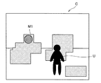
図14は、図9に示した環境Cに、プロジェクタ30から映像が投影された状態を示す説明図である。図14には、図10に示したような映像に加え、モグラM1がプロジェクタ30から環境Cに照射されている状態が示されている。このようにプロジェクタ30から映像を投影することで、プロジェクタ30から照射されているモグラM1の映像にユーザUが触れるとモグラUが消滅するようなモグラ叩きゲームが、投影型拡張現実感システム1によって実現可能となる。
FIG. 14 is an explanatory diagram showing a state in which an image is projected from the
図15は、図9に示した環境Cに、プロジェクタ30から映像が投影された状態を示す説明図である。図15には、図14に示したモグラM1の映像にユーザUが触れた状態が示されている。図15のように、モグラM1の映像にユーザUが触れたことがインタラクション解析部120の解析結果によって判定されれば、投影映像生成部130はモグラM1の表示をやめる。
FIG. 15 is an explanatory diagram illustrating a state in which an image is projected from the
図16は、図9に示した環境Cに、プロジェクタ30から映像が投影された状態を示す説明図である。図16には、図10に示したような映像に加え、モグラM2がプロジェクタ30から環境Cに照射されている状態が示されている。図16に示したように、モグラM1の映像に触れた後に、ユーザUが急げばぎりぎりモグラM2の映像に届くような場所に表示されるよう、投影映像生成部130がこのモグラM2の表示位置を決定する。
FIG. 16 is an explanatory diagram illustrating a state in which an image is projected from the
このようにプロジェクタ30から映像を投影することで、ユーザUがモグラM1、M2の映像に触れたことがインタラクション解析部120の解析結果によって判定されれば得点が与えられるようなモグラ叩きゲームが、投影型拡張現実感システム1によって実現可能となる。
By projecting the image from the
[1.4.3.エクサササイズアプリケーションの実現]
続いて、映像生成装置100が生成する映像をプロジェクタ30から投影することで、投影型拡張現実感システム1がエクサササイズアプリケーションを実現する例を説明する。投影型拡張現実感システム1は、プロジェクタ30が映像を投影する環境と、予め登録されたユーザの健康状態等の情報とに基づいて、その環境でユーザにとって最適なエクササイズを提供することができる。ユーザの健康状態等の情報には、例えば、ユーザの性別、年齢、身長、体重、血圧、心拍数等の情報が含まれ得る。
[1.4.3. Realization of exercise application]
Subsequently, an example in which the projection augmented reality system 1 realizes an exercise application by projecting the video generated by the
図17は、図9に示した環境Cに、プロジェクタ30から映像が投影された状態を示す説明図である。図17には、図10に示したような映像に加え、ユーザUが手や足で触る目印M1がプロジェクタ30から環境Cに照射されている状態が示されている。
FIG. 17 is an explanatory diagram illustrating a state in which an image is projected from the
図17に示したように、ユーザUにとって最適なエクササイズ効果が出るような位置に目印M1の映像が表示されるよう、投影映像生成部130がこの目印M1の表示位置を決定する。目印M1の表示位置は、プロジェクタ30が映像を投影する環境におけるアフォーダンスだけでなく、ユーザの健康状態等の情報にも基づいて決定され得る。図17に示した例では、ユーザUが手を乗せることが出来るとアフォーダンス解析部110が判断し、かつ、ユーザUにとって最適なエクササイズ効果が出ると判断した位置に目印M1が表示されるよう、投影映像生成部130がプロジェクタ30から投影される映像を生成している。
As shown in FIG. 17, the projection
このようにプロジェクタ30から映像を投影することで、ユーザUが目印M1の映像に触ることでユーザUにエクササイズ効果が出るようなエクサササイズアプリケーションが、投影型拡張現実感システム1によって実現可能となる。
By projecting an image from the
投影型拡張現実感システム1がエクサササイズアプリケーションを実現する場合は、ユーザが希望するエクササイズの種類に応じて環境に投影される映像を投影映像生成部130が生成しても良い。例えば瞬発力を鍛えるエクササイズをユーザが希望する場合は、短時間で目印の位置が変化するような映像を投影映像生成部130が生成し、筋力を鍛えるエクササイズをユーザが希望する場合は、目印の位置が変化しないような映像を投影映像生成部130が生成してもよい。
When the projection augmented reality system 1 realizes an exercise application, the projection
なお、投影型拡張現実感システム1によって実現できるゲームやアプリケーションは上述してきた例に限定されないことは言うまでもない。 Needless to say, games and applications that can be realized by the projected augmented reality system 1 are not limited to the examples described above.
<2.ハードウェア構成例>
上記の各アルゴリズムは、例えば、図18に示す情報処理装置のハードウェア構成を用いて実行することが可能である。つまり、当該各アルゴリズムの処理は、コンピュータプログラムを用いて図18に示すハードウェアを制御することにより実現される。なお、このハードウェアの形態は任意であり、例えば、パーソナルコンピュータ、携帯電話、PHS、PDA等の携帯情報端末、ゲーム機、接触式又は非接触式のICチップ、接触式又は非接触式のICカード、又は種々の情報家電がこれに含まれる。但し、上記のPHSは、Personal Handy−phone Systemの略である。また、上記のPDAは、Personal Digital Assistantの略である。
<2. Hardware configuration example>
Each of the algorithms described above can be executed using, for example, the hardware configuration of the information processing apparatus illustrated in FIG. That is, the processing of each algorithm is realized by controlling the hardware shown in FIG. 18 using a computer program. The form of this hardware is arbitrary, for example, personal information terminals such as personal computers, mobile phones, PHS, PDAs, game machines, contact or non-contact IC chips, contact or non-contact ICs This includes cards or various information appliances. However, the above PHS is an abbreviation of Personal Handy-phone System. The PDA is an abbreviation for Personal Digital Assistant.
図18に示すように、このハードウェアは、主に、CPU902と、ROM904と、RAM906と、ホストバス908と、ブリッジ910と、を有する。さらに、このハードウェアは、外部バス912と、インターフェース914と、入力部916と、出力部918と、記憶部920と、ドライブ922と、接続ポート924と、通信部926と、を有する。但し、上記のCPUは、Central Processing Unitの略である。また、上記のROMは、Read Only Memoryの略である。そして、上記のRAMは、Random Access Memoryの略である。
As shown in FIG. 18, this hardware mainly includes a
CPU902は、例えば、演算処理装置又は制御装置として機能し、ROM904、RAM906、記憶部920、又はリムーバブル記録媒体928に記録された各種プログラムに基づいて各構成要素の動作全般又はその一部を制御する。ROM904は、CPU902に読み込まれるプログラムや演算に用いるデータ等を格納する手段である。RAM906には、例えば、CPU902に読み込まれるプログラムや、そのプログラムを実行する際に適宜変化する各種パラメータ等が一時的又は永続的に格納される。
The
これらの構成要素は、例えば、高速なデータ伝送が可能なホストバス908を介して相互に接続される。一方、ホストバス908は、例えば、ブリッジ910を介して比較的データ伝送速度が低速な外部バス912に接続される。また、入力部916としては、例えば、マウス、キーボード、タッチパネル、ボタン、スイッチ、センサ、カメラ及びレバー等が用いられる。さらに、入力部916としては、赤外線やその他の電波を利用して制御信号を送信することが可能なリモートコントローラ(以下、リモコン)が用いられることもある。
These components are connected to each other via, for example, a
出力部918としては、例えば、プロジェクタ、CRT、LCD、PDP、又はELD等のディスプレイ装置、スピーカ、ヘッドホン等のオーディオ出力装置、プリンタ、携帯電話、又はファクシミリ等、取得した情報を利用者に対して視覚的又は聴覚的に通知することが可能な装置である。但し、上記のCRTは、Cathode Ray Tubeの略である。また、上記のLCDは、Liquid Crystal Displayの略である。そして、上記のPDPは、Plasma DisplayPanelの略である。さらに、上記のELDは、Electro−Luminescence Displayの略である。
As the
記憶部920は、各種のデータを格納するための装置である。記憶部920としては、例えば、ハードディスクドライブ(HDD)等の磁気記憶デバイス、半導体記憶デバイス、光記憶デバイス、又は光磁気記憶デバイス等が用いられる。但し、上記のHDDは、Hard Disk Driveの略である。
The
ドライブ922は、例えば、磁気ディスク、光ディスク、光磁気ディスク、又は半導体メモリ等のリムーバブル記録媒体928に記録された情報を読み出し、又はリムーバブル記録媒体928に情報を書き込む装置である。リムーバブル記録媒体928は、例えば、DVDメディア、Blu−rayメディア、HD DVDメディア、各種の半導体記憶メディア等である。もちろん、リムーバブル記録媒体928は、例えば、非接触型ICチップを搭載したICカード、又は電子機器等であってもよい。但し、上記のICは、Integrated Circuitの略である。
The
接続ポート924は、例えば、USBポート、IEEE1394ポート、SCSI、RS−232Cポート、又は光オーディオ端子等のような外部接続機器930を接続するためのポートである。外部接続機器930は、例えば、プリンタ、携帯音楽プレーヤ、デジタルカメラ、デジタルビデオカメラ、又はICレコーダ等である。但し、上記のUSBは、Universal Serial Busの略である。また、上記のSCSIは、Small Computer System Interfaceの略である。
The
通信部926は、ネットワーク932に接続するための通信デバイスであり、例えば、有線又は無線LAN、Bluetooth(登録商標)、又はWUSB用の通信カード、光通信用のルータ、ADSL用のルータ、又は接触又は非接触通信用のデバイス等である。また、通信部926に接続されるネットワーク932は、有線又は無線により接続されたネットワークにより構成され、例えば、インターネット、家庭内LAN、赤外線通信、可視光通信、放送、又は衛星通信等である。但し、上記のLANは、Local Area Networkの略である。また、上記のWUSBは、Wireless USBの略である。そして、上記のADSLは、Asymmetric Digital Subscriber Lineの略である。
The
<3.まとめ>
以上説明したように、本開示の一実施形態によれば、環境のアフォーダンス(行動実現可能性)を解析し、そのアフォーダンスに基づいて環境に投影する映像を生成する、映像生成装置100が提供される。
<3. Summary>
As described above, according to an embodiment of the present disclosure, there is provided the
映像生成装置100は、深度センサ10から送られてくる深度データを用いた環境のアフォーダンスの解析をアフォーダンス解析部110で実行する。アフォーダンス解析部110は、深度データから得られる環境の3次元データについて、ユーザの採り得る行動の実現可能性を決定する。アフォーダンス解析部110は、ユーザの採り得る行動の実現可能性を決定する際には行動可否データベース140に格納されている情報と照合する。
The
本開示の一実施形態に係る映像生成装置100は、環境のアフォーダンス(行動実現可能性)を解析し、そのアフォーダンスに基づいて環境に投影する映像を生成することで、人間にとっての環境の行動実現可能性を自動的に理解して、その行動実現可能性を投影する映像に反映することができる。
The
本明細書の各装置が実行する処理における各ステップは、必ずしもシーケンス図またはフローチャートとして記載された順序に沿って時系列に処理する必要はない。例えば、各装置が実行する処理における各ステップは、フローチャートとして記載した順序と異なる順序で処理されても、並列的に処理されてもよい。 Each step in the processing executed by each device in the present specification does not necessarily have to be processed in time series in the order described as a sequence diagram or flowchart. For example, each step in the processing executed by each device may be processed in an order different from the order described as the flowchart, or may be processed in parallel.
また、各装置に内蔵されるCPU、ROMおよびRAMなどのハードウェアを、上述した各装置の構成と同等の機能を発揮させるためのコンピュータプログラムも作成可能である。また、該コンピュータプログラムを記憶させた記憶媒体も提供されることが可能である。また、機能ブロック図で示したそれぞれの機能ブロックをハードウェアで構成することで、一連の処理をハードウェアで実現することもできる。 In addition, it is possible to create a computer program for causing hardware such as a CPU, ROM, and RAM incorporated in each device to exhibit functions equivalent to the configuration of each device described above. A storage medium storing the computer program can also be provided. Moreover, a series of processes can also be realized by hardware by configuring each functional block shown in the functional block diagram with hardware.
以上、添付図面を参照しながら本開示の好適な実施形態について詳細に説明したが、本開示の技術的範囲はかかる例に限定されない。本開示の技術分野における通常の知識を有する者であれば、特許請求の範囲に記載された技術的思想の範疇内において、各種の変更例または修正例に想到し得ることは明らかであり、これらについても、当然に本開示の技術的範囲に属するものと了解される。 The preferred embodiments of the present disclosure have been described in detail above with reference to the accompanying drawings, but the technical scope of the present disclosure is not limited to such examples. It is obvious that a person having ordinary knowledge in the technical field of the present disclosure can come up with various changes or modifications within the scope of the technical idea described in the claims. Of course, it is understood that it belongs to the technical scope of the present disclosure.
また、本明細書に記載された効果は、あくまで説明的または例示的なものであって限定的ではない。つまり、本開示に係る技術は、上記の効果とともに、または上記の効果に代えて、本明細書の記載から当業者には明らかな他の効果を奏しうる。 Further, the effects described in the present specification are merely illustrative or exemplary and are not limited. That is, the technology according to the present disclosure can exhibit other effects that are apparent to those skilled in the art from the description of the present specification in addition to or instead of the above effects.
例えば、上記実施形態では、プロジェクタ30のみから映像が出力されていたが、本開示は係る例に限定されるものではない。環境のアフォーダンスを考慮した映像は、プロジェクタに加えて映像を表示するディスプレイからも表示され得る。
For example, in the above embodiment, the video is output only from the
なお、以下のような構成も本開示の技術的範囲に属する。
(1)
環境の三次元形状のデータを取得し、前記三次元形状のデータの分析により、前記ユーザにとっての該環境の行動実現可能性を解析する行動実現可能性解析部と、
前記行動実現可能性解析部の解析結果を用いて前記環境へ投影する映像を生成する映像生成部と、
を備える、情報処理装置。
(2)
前記行動実現可能性解析部は、前記環境の所定の位置を含んだ所定の範囲における前記三次元形状のデータに対して前記ユーザの行動可否を評価することで、前記所定の位置における前記環境の行動実現可能性を解析する、前記(1)に記載の情報処理装置。
(3)
ユーザの行動の実行可否が形状ごとに記録された行動実行可否データベースをさらに備え、
前記行動実現可能性解析部は、前記行動実行可否データベースに保持されたデータと照らし合わせることで前記ユーザの行動可否を評価する、前記(2)に記載の情報処理装置。
(4)
前記行動実現可能性解析部は、サポートベクタマシンを使用して前記行動実行可否データベースに保持されたデータと照らし合わせる、前記(3)に記載の情報処理装置。
(5)
前記行動実行可否データベースは、ランダムに生成された環境に対するシミュレーションによりユーザの行動の実行可否が形状ごとに記録される、前記(3)または(4)に記載の情報処理装置。
(6)
前記行動実現可能性解析部は、ユーザの所定の行動については前記三次元形状のデータを直接解析して前記ユーザの行動可否を評価する、前記(2)〜(5)のいずれかに記載の情報処理装置。
(7)
前記三次元形状のデータの分析により前記環境におけるユーザの動作を解析するインタラクション解析部をさらに備える、前記(1)〜(7)のいずれかに記載の情報処理装置。
(8)
前記映像生成部は、前記行動実現可能性解析部の解析結果及び前記インタラクション解析部の解析結果を用いて投影する映像を生成する、前記(7)に記載の情報処理装置。
(9)
前記環境の三次元形状のデータは、少なくとも1つの深度センサにより取得された深度データに基づく、前記(1)〜(8)のいずれかに記載の情報処理装置。
(10)
環境の三次元形状のデータを取得し、前記三次元形状のデータの分析により、前記ユーザにとっての該環境の行動実現可能性を解析するステップと、
解析された前記行動実現可能性を用いて前記環境へ投影する映像を生成するステップと、
を備える、情報処理方法。
(11)
コンピュータに、
環境の三次元形状のデータを取得し、前記三次元形状のデータの分析により、前記ユーザにとっての該環境の行動実現可能性を解析するステップと、
解析された前記行動実現可能性を用いて前記環境へ投影する映像を生成するステップと、
を実行させる、コンピュータプログラム。
The following configurations also belong to the technical scope of the present disclosure.
(1)
An action feasibility analysis unit that acquires data of the three-dimensional shape of the environment and analyzes the action feasibility of the environment for the user by analyzing the data of the three-dimensional shape;
A video generation unit that generates a video to be projected to the environment using the analysis result of the action feasibility analysis unit;
An information processing apparatus comprising:
(2)
The action feasibility analysis unit evaluates whether or not the user can act on the three-dimensional shape data in a predetermined range including the predetermined position of the environment, so that the environment at the predetermined position is evaluated. The information processing apparatus according to (1), wherein the action feasibility is analyzed.
(3)
An action execution availability database in which whether or not the user's action can be executed is recorded for each shape;
The information processing apparatus according to (2), wherein the action feasibility analysis unit evaluates the user's action availability by comparing with data held in the action execution availability database.
(4)
The information processing apparatus according to (3), wherein the action feasibility analysis unit compares data stored in the action execution availability database using a support vector machine.
(5)
The information processing apparatus according to (3) or (4), wherein the action execution possibility database records, for each shape, whether or not a user's action can be executed by a simulation with respect to a randomly generated environment.
(6)
The behavior feasibility analysis unit according to any one of (2) to (5), wherein the user's predetermined behavior is directly analyzed with respect to the three-dimensional shape data to evaluate the user's behavior. Information processing device.
(7)
The information processing apparatus according to any one of (1) to (7), further including an interaction analysis unit that analyzes a user's operation in the environment by analyzing the three-dimensional shape data.
(8)
The information processing apparatus according to (7), wherein the video generation unit generates a video to be projected using the analysis result of the action feasibility analysis unit and the analysis result of the interaction analysis unit.
(9)
The information processing apparatus according to any one of (1) to (8), wherein the three-dimensional shape data of the environment is based on depth data acquired by at least one depth sensor.
(10)
Acquiring three-dimensional shape data of the environment, and analyzing the action feasibility of the environment for the user by analyzing the three-dimensional shape data;
Generating an image to be projected to the environment using the analyzed action feasibility;
An information processing method comprising:
(11)
On the computer,
Acquiring three-dimensional shape data of the environment, and analyzing the action feasibility of the environment for the user by analyzing the three-dimensional shape data;
Generating an image to be projected to the environment using the analyzed action feasibility;
A computer program that executes
1 投影型拡張現実感システム
10 深度センサ
20 RGBカメラ
30 プロジェクタ
100 映像生成装置
C 環境
U ユーザ
DESCRIPTION OF SYMBOLS 1 Projection type augmented
Claims (9)
前記行動実現可能性解析部の解析結果を用いて前記現実環境へ投影する映像を生成する映像生成部と、
前記ユーザの行動の実行可否が物体の形状ごとに記録された行動実行可否データベースと、
を備え、
前記行動実現可能性解析部は、前記行動実行可否データベースに保持されたデータと照らし合わせることで、前記現実環境の所定の位置を含んだ所定の範囲における前記三次元形状のデータに対して前記ユーザの行動可否を評価する、情報処理装置。 Get the data of the three-dimensional shape of the real environment, the analysis of the data of the three-dimensional shape, the reality in the real environment to be analyzed for the typical user to the shape of the body performs a predetermined modeling An action feasibility analysis unit that analyzes the action feasibility of
A video generation unit that generates a video to be projected to the real environment using the analysis result of the action feasibility analysis unit;
Action execution availability database in which whether or not the user's action can be executed is recorded for each shape of the object;
Equipped with a,
The action feasibility analysis unit compares the data stored in the action execution availability database with respect to the three-dimensional shape data in a predetermined range including a predetermined position in the real environment. We evaluate the actions propriety, the information processing apparatus.
前記ユーザの行動の実行可否が物体の形状ごとに記録された行動実行可否データベースに保持されたデータと照らし合わせて前記現実環境の所定の位置を含んだ所定の範囲における前記三次元形状のデータに対して前記ユーザの行動可否を評価することにより解析された前記行動実現可能性を用いて前記現実環境へ投影する映像を生成するステップと、
を備える、情報処理方法。 Get the data of the three-dimensional shape of the real environment, the analysis of the data of the three-dimensional shape, the reality in the real environment to be analyzed for the typical user to the shape of the body performs a predetermined modeling Analyzing the action feasibility of
The three-dimensional shape data in a predetermined range including the predetermined position of the real environment in comparison with the data held in the behavior execution propriety database recorded for each shape of the object whether or not the user's behavior can be executed Generating an image to be projected onto the real environment using the action feasibility analyzed by evaluating the user's action availability ;
An information processing method comprising:
現実環境の三次元形状のデータを取得し、前記三次元形状のデータの分析により、体の形状について所定のモデル化を行った代表的なユーザにとっての解析の対象となる該現実環境での現実の行動実現可能性を解析するステップと、
前記ユーザの行動の実行可否が物体の形状ごとに記録された行動実行可否データベースに保持されたデータと照らし合わせて前記現実環境の所定の位置を含んだ所定の範囲における前記三次元形状のデータに対して前記ユーザの行動可否を評価することにより解析された前記行動実現可能性を用いて前記現実環境へ投影する映像を生成するステップと、
を実行させる、コンピュータプログラム。
On the computer,
Get the data of the three-dimensional shape of the real environment, the analysis of the data of the three-dimensional shape, the reality in the real environment to be analyzed for the typical user to the shape of the body performs a predetermined modeling Analyzing the action feasibility of
The three-dimensional shape data in a predetermined range including the predetermined position of the real environment in comparison with the data held in the behavior execution propriety database recorded for each shape of the object whether or not the user's behavior can be executed Generating an image to be projected onto the real environment using the action feasibility analyzed by evaluating the user's action availability ;
A computer program that executes
Priority Applications (5)
| Application Number | Priority Date | Filing Date | Title |
|---|---|---|---|
| JP2013191634A JP6263917B2 (en) | 2013-09-17 | 2013-09-17 | Information processing apparatus, information processing method, and computer program |
| CN201480050007.2A CN105531756B (en) | 2013-09-17 | 2014-09-05 | Information processor, information processing method and recording medium |
| EP14845445.7A EP3048605B1 (en) | 2013-09-17 | 2014-09-05 | Information processing device, information processing method, and computer program |
| US14/917,487 US10565436B2 (en) | 2013-09-17 | 2014-09-05 | Information processing device and information processing method |
| PCT/JP2014/073570 WO2015041079A1 (en) | 2013-09-17 | 2014-09-05 | Information processing device, information processing method, and computer program |
Applications Claiming Priority (1)
| Application Number | Priority Date | Filing Date | Title |
|---|---|---|---|
| JP2013191634A JP6263917B2 (en) | 2013-09-17 | 2013-09-17 | Information processing apparatus, information processing method, and computer program |
Publications (3)
| Publication Number | Publication Date |
|---|---|
| JP2015059965A JP2015059965A (en) | 2015-03-30 |
| JP2015059965A5 JP2015059965A5 (en) | 2016-02-12 |
| JP6263917B2 true JP6263917B2 (en) | 2018-01-24 |
Family
ID=52688730
Family Applications (1)
| Application Number | Title | Priority Date | Filing Date |
|---|---|---|---|
| JP2013191634A Expired - Fee Related JP6263917B2 (en) | 2013-09-17 | 2013-09-17 | Information processing apparatus, information processing method, and computer program |
Country Status (5)
| Country | Link |
|---|---|
| US (1) | US10565436B2 (en) |
| EP (1) | EP3048605B1 (en) |
| JP (1) | JP6263917B2 (en) |
| CN (1) | CN105531756B (en) |
| WO (1) | WO2015041079A1 (en) |
Families Citing this family (10)
| Publication number | Priority date | Publication date | Assignee | Title |
|---|---|---|---|---|
| US10404938B1 (en) | 2015-12-22 | 2019-09-03 | Steelcase Inc. | Virtual world method and system for affecting mind state |
| JP6679966B2 (en) * | 2016-02-05 | 2020-04-15 | 凸版印刷株式会社 | Three-dimensional virtual space presentation system, three-dimensional virtual space presentation method and program |
| US10181218B1 (en) | 2016-02-17 | 2019-01-15 | Steelcase Inc. | Virtual affordance sales tool |
| US10182210B1 (en) * | 2016-12-15 | 2019-01-15 | Steelcase Inc. | Systems and methods for implementing augmented reality and/or virtual reality |
| CN106803913A (en) * | 2017-03-10 | 2017-06-06 | 武汉东信同邦信息技术有限公司 | A kind of detection method and its device of the action that taken the floor for Auto-Sensing student |
| JP7029722B2 (en) * | 2017-10-23 | 2022-03-04 | 株式会社Splink | AR equipment, methods and programs |
| CN108635853B (en) * | 2018-03-23 | 2019-06-21 | 腾讯科技(深圳)有限公司 | The control method and device of object, storage medium, electronic device |
| CN109847350A (en) * | 2019-03-25 | 2019-06-07 | 深圳初影科技有限公司 | Game implementation method, game system and storage medium based on AR technology |
| US11494953B2 (en) * | 2019-07-01 | 2022-11-08 | Microsoft Technology Licensing, Llc | Adaptive user interface palette for augmented reality |
| US11832560B1 (en) | 2019-08-08 | 2023-12-05 | Valmont Industries, Inc. | System and method for detecting and aligning the orientation of an irrigation system within a display |
Family Cites Families (21)
| Publication number | Priority date | Publication date | Assignee | Title |
|---|---|---|---|---|
| US5548694A (en) * | 1995-01-31 | 1996-08-20 | Mitsubishi Electric Information Technology Center America, Inc. | Collision avoidance system for voxel-based object representation |
| JPH11300049A (en) * | 1998-04-20 | 1999-11-02 | Hitachi Ltd | Shooting game device |
| US6362817B1 (en) * | 1998-05-18 | 2002-03-26 | In3D Corporation | System for creating and viewing 3D environments using symbolic descriptors |
| US6712703B2 (en) * | 1998-11-19 | 2004-03-30 | Nintendo Co., Ltd. | Video game apparatus and information storage medium for video game |
| JP3944019B2 (en) * | 2002-07-31 | 2007-07-11 | キヤノン株式会社 | Information processing apparatus and method |
| US8902227B2 (en) * | 2007-09-10 | 2014-12-02 | Sony Computer Entertainment America Llc | Selective interactive mapping of real-world objects to create interactive virtual-world objects |
| US8251521B2 (en) * | 2007-09-14 | 2012-08-28 | Panasonic Corporation | Projector having a projection angle adjusting mechanism |
| JP2009093376A (en) * | 2007-10-05 | 2009-04-30 | Sony Corp | Signal processing system, signal processing method, and program |
| US8126221B2 (en) * | 2008-02-14 | 2012-02-28 | Ecole Polytechnique Federale De Lausanne (Epfl) | Interactive device and method for transmitting commands from a user |
| JP5315111B2 (en) * | 2009-03-31 | 2013-10-16 | 株式会社エヌ・ティ・ティ・ドコモ | Terminal device, information presentation system, and terminal screen display method |
| US8730309B2 (en) * | 2010-02-23 | 2014-05-20 | Microsoft Corporation | Projectors and depth cameras for deviceless augmented reality and interaction |
| US8217997B2 (en) * | 2010-03-16 | 2012-07-10 | Interphase Corporation | Interactive display system |
| CN102959616B (en) * | 2010-07-20 | 2015-06-10 | 苹果公司 | Interactive reality augmentation for natural interaction |
| JP2012155655A (en) * | 2011-01-28 | 2012-08-16 | Sony Corp | Information processing device, notification method, and program |
| JP2012173772A (en) * | 2011-02-17 | 2012-09-10 | Panasonic Corp | User interaction apparatus, user interaction method, user interaction program and integrated circuit |
| JP5960796B2 (en) * | 2011-03-29 | 2016-08-02 | クアルコム,インコーポレイテッド | Modular mobile connected pico projector for local multi-user collaboration |
| US20140063061A1 (en) * | 2011-08-26 | 2014-03-06 | Reincloud Corporation | Determining a position of an item in a virtual augmented space |
| JP5807686B2 (en) * | 2012-02-10 | 2015-11-10 | ソニー株式会社 | Image processing apparatus, image processing method, and program |
| JP2013172432A (en) * | 2012-02-23 | 2013-09-02 | Panasonic Corp | Equipment control apparatus, equipment control method, equipment control program, and integrated circuit |
| US8933970B2 (en) * | 2012-09-11 | 2015-01-13 | Longsand Limited | Controlling an augmented reality object |
| US9552673B2 (en) * | 2012-10-17 | 2017-01-24 | Microsoft Technology Licensing, Llc | Grasping virtual objects in augmented reality |
-
2013
- 2013-09-17 JP JP2013191634A patent/JP6263917B2/en not_active Expired - Fee Related
-
2014
- 2014-09-05 EP EP14845445.7A patent/EP3048605B1/en not_active Not-in-force
- 2014-09-05 WO PCT/JP2014/073570 patent/WO2015041079A1/en active Application Filing
- 2014-09-05 US US14/917,487 patent/US10565436B2/en not_active Expired - Fee Related
- 2014-09-05 CN CN201480050007.2A patent/CN105531756B/en not_active Expired - Fee Related
Also Published As
| Publication number | Publication date |
|---|---|
| EP3048605A4 (en) | 2017-05-10 |
| CN105531756A (en) | 2016-04-27 |
| CN105531756B (en) | 2017-11-24 |
| WO2015041079A1 (en) | 2015-03-26 |
| US10565436B2 (en) | 2020-02-18 |
| EP3048605B1 (en) | 2019-03-20 |
| EP3048605A1 (en) | 2016-07-27 |
| JP2015059965A (en) | 2015-03-30 |
| US20160217323A1 (en) | 2016-07-28 |
Similar Documents
| Publication | Publication Date | Title |
|---|---|---|
| JP6263917B2 (en) | Information processing apparatus, information processing method, and computer program | |
| US10761612B2 (en) | Gesture recognition techniques | |
| US10960298B2 (en) | Boolean/float controller and gesture recognition system | |
| US9342160B2 (en) | Ergonomic physical interaction zone cursor mapping | |
| US10257423B2 (en) | Method and system for determining proper positioning of an object | |
| US8730309B2 (en) | Projectors and depth cameras for deviceless augmented reality and interaction | |
| JP6002424B2 (en) | System and method for providing feedback by user's line of sight and gesture | |
| US9626801B2 (en) | Visualization of physical characteristics in augmented reality | |
| KR102162373B1 (en) | Associating an object with a subject | |
| US20160314620A1 (en) | Virtual reality sports training systems and methods | |
| WO2019100754A1 (en) | Human body movement identification method and device, and electronic device | |
| US9384329B2 (en) | Caloric burn determination from body movement | |
| KR20120123330A (en) | Camera navigation for presentations | |
| RU2643444C2 (en) | Visualization and accuracy of reproduction based on attention | |
| JP2019067323A (en) | Information processing apparatus, information processing method, and recording medium | |
| CN106504001A (en) | Method of payment and device in a kind of VR environment | |
| Tseng et al. | Interaction design in virtual reality game using Arduino sensors | |
| KR20170081889A (en) | Method for providing user interface for card game, and server and computer-readable recording media using the same | |
| EP2540090A2 (en) | Projectors and depth cameras for deviceless augmented reality and interaction |
Legal Events
| Date | Code | Title | Description |
|---|---|---|---|
| A521 | Request for written amendment filed |
Free format text: JAPANESE INTERMEDIATE CODE: A523 Effective date: 20151217 |
|
| A621 | Written request for application examination |
Free format text: JAPANESE INTERMEDIATE CODE: A621 Effective date: 20151217 |
|
| A131 | Notification of reasons for refusal |
Free format text: JAPANESE INTERMEDIATE CODE: A131 Effective date: 20160913 |
|
| A521 | Request for written amendment filed |
Free format text: JAPANESE INTERMEDIATE CODE: A523 Effective date: 20161107 |
|
| A131 | Notification of reasons for refusal |
Free format text: JAPANESE INTERMEDIATE CODE: A131 Effective date: 20170425 |
|
| A521 | Request for written amendment filed |
Free format text: JAPANESE INTERMEDIATE CODE: A523 Effective date: 20170619 |
|
| TRDD | Decision of grant or rejection written | ||
| A01 | Written decision to grant a patent or to grant a registration (utility model) |
Free format text: JAPANESE INTERMEDIATE CODE: A01 Effective date: 20171121 |
|
| A61 | First payment of annual fees (during grant procedure) |
Free format text: JAPANESE INTERMEDIATE CODE: A61 Effective date: 20171204 |
|
| R151 | Written notification of patent or utility model registration |
Ref document number: 6263917 Country of ref document: JP Free format text: JAPANESE INTERMEDIATE CODE: R151 |
|
| LAPS | Cancellation because of no payment of annual fees |