JP6263786B2 - Ozone generation module - Google Patents
Ozone generation module Download PDFInfo
- Publication number
- JP6263786B2 JP6263786B2 JP2012254108A JP2012254108A JP6263786B2 JP 6263786 B2 JP6263786 B2 JP 6263786B2 JP 2012254108 A JP2012254108 A JP 2012254108A JP 2012254108 A JP2012254108 A JP 2012254108A JP 6263786 B2 JP6263786 B2 JP 6263786B2
- Authority
- JP
- Japan
- Prior art keywords
- pyroelectric crystal
- ozone
- heat sink
- pyroelectric
- crystal
- Prior art date
- Legal status (The legal status is an assumption and is not a legal conclusion. Google has not performed a legal analysis and makes no representation as to the accuracy of the status listed.)
- Active
Links
Images


Landscapes
- Oxygen, Ozone, And Oxides In General (AREA)
Description
本発明は、オゾン発生用モジュール、特に、焦電性結晶体を用いたオゾン発生用モジュールに関するものである。 The present invention relates to an ozone generation module, and more particularly to an ozone generation module using a pyroelectric crystal.
オゾンは、その強い酸化性によって優れた殺菌性や脱臭性を発揮するので、近年、空気清浄器や冷蔵庫等にオゾン発生器を備えることが盛んに行われている。 Since ozone exhibits excellent bactericidal and deodorizing properties due to its strong oxidizing properties, in recent years, ozone generators are actively provided in air purifiers, refrigerators, and the like.
従来のオゾン発生器は、空気に紫外線を照射し、あるいは酸素中で無声放電を行い、高エネルギーをもつ電子と酸素分子を衝突させることによってオゾンを発生させている。
しかし、この従来のオゾン発生器は、構造が大がかりであり、電力消費量も多く、さらには、発生するオゾンを定量的に制御することが容易ではないという問題を有していた。
Conventional ozone generators generate ozone by irradiating air with ultraviolet rays or performing silent discharge in oxygen to collide high-energy electrons with oxygen molecules.
However, this conventional ozone generator has a problem that the structure is large, the power consumption is large, and furthermore, it is not easy to quantitatively control the generated ozone.
また、本発明者の一部は、焦電性結晶体の加熱および冷却を繰り返すことによるオゾン発生方式をこれまでに開発しており(例えば、特許文献1、2参照)、この方式によれば、構造が簡単で、電力消費量の少ないオゾン発生器を容易に実現することができる。
In addition, some of the inventors have developed an ozone generation method by repeating heating and cooling of a pyroelectric crystal (see, for example,
ところで、オゾンは優れた殺菌性や脱臭性を発揮するものの、高濃度になると人体の健康に被害を及ぼしてしまう。そのため、オゾン発生器においては、発生するオゾンを定量的に制御することによって、常時適切な濃度のオゾンを発生させなければならない。
しかしながら、この従来の焦電性結晶体を用いたオゾン発生器においては、発生するオゾンを定量的に制御することが容易ではなかった。
By the way, ozone exhibits excellent bactericidal and deodorizing properties, but if it becomes a high concentration, it will damage human health. Therefore, in an ozone generator, it is necessary to always generate ozone having an appropriate concentration by quantitatively controlling the generated ozone.
However, in the conventional ozone generator using the pyroelectric crystal, it is not easy to quantitatively control the generated ozone.
したがって、本発明の課題は、従来の焦電性結晶体を用いたオゾン発生器を改良し、オゾンの発生の定量的な制御が可能で、コンパクトかつ電力消費量の少ないオゾン発生用モジュールを提供することにある。 Therefore, an object of the present invention is to provide an ozone generation module that improves the conventional ozone generator using a pyroelectric crystal, can control the generation of ozone quantitatively, and is compact and consumes less power. There is to do.
上記課題を解決するため、本発明は、大気中に配置されるとともに、オゾン発生部と、前記オゾン発生部に電力を供給する電源部と、前記電源部による電力供給を制御する制御部と、を備え、前記オゾン発生部は、少なくとも1つの焦電性結晶体と、前記焦電性結晶体が電気絶縁された状態で取り付けられたヒートシンクと、前記ヒートシンクに支持部材を介して取り付けられ、前記焦電結晶体の上方において前記焦電結晶体に対向して配置されたファンと、前記焦電性結晶体または前記ヒートシンクに電気絶縁された状態で取り付けられ、前記焦電性結晶体に電気絶縁された状態で接触するヒーターと、を有し、前記ヒーターが、前記電源部からの供給電圧と、前記焦電性結晶体に対する予め決定された最適電流値と、からオームの法則に従って算出された抵抗値を有しており、前記ファンによって前記焦電結晶体に吹き付ける前記大気の流れが形成されるとともに、前記ヒーターに対し一定の時間間隔ごとに一定の継続時間だけ前記電力供給がなされることによって前記焦電性結晶体の温度昇降が繰り返され、前記大気の流れ中の酸素分子が前記焦電結晶体から発生したX線および電界によりオゾン化されるようになっており、前記焦電性結晶体に対する前記最適電流値は、予め決定された濃度のオゾンを発生させるべく、前記焦電性結晶体の最高温度が予め決定された範囲内に維持されつつ、予め決定された温度差の範囲内で前記焦電性結晶体の温度昇降が繰り返されるような電流値として予め決定されていることを特徴とするオゾン発生用モジュールを構成したものである。 In order to solve the above problems, the present invention is arranged in the atmosphere, an ozone generator, a power supply that supplies power to the ozone generator, a controller that controls power supply by the power supply, Bei example, the ozone generating unit includes at least one pyroelectric crystal body, and a heat sink attached in a state in which the pyroelectric crystal body is electrically insulated, it mounted via a support member to the heat sink, A fan disposed above the pyroelectric crystal body and facing the pyroelectric crystal body is attached in an electrically insulated state to the pyroelectric crystal body or the heat sink, and is electrically connected to the pyroelectric crystal body. A heater that is in contact with each other in an insulated state, wherein the heater is in accordance with Ohm's law from a supply voltage from the power supply unit and a predetermined optimum current value for the pyroelectric crystal. Has a resistance value calculated I, wherein with the flow of the air blown to the pyroelectric crystal body is formed by the fan, the only fixed duration for each predetermined time interval with respect to the heater power When the supply is made, the temperature of the pyroelectric crystal is repeatedly raised and lowered, and oxygen molecules in the atmospheric flow are ozonized by X-rays and electric fields generated from the pyroelectric crystal. The optimum current value for the pyroelectric crystal is predetermined while maintaining the maximum temperature of the pyroelectric crystal within a predetermined range so as to generate ozone having a predetermined concentration. The ozone generation module is characterized in that the current value is determined in advance so that the temperature rise and fall of the pyroelectric crystal body is repeated within the range of the temperature difference.
上記構成において、好ましくは、前記焦電性結晶体は、矩形平板状を有し、一面が正の電気面をなす一方、他面が負の電気面をなしており、前記ヒートシンクの平坦な固定面上に、前記一面または前記他面を下にして置かれ、前記ヒートシンクの前記固定面における前記焦電性結晶体の両側には、前記焦電性結晶体の厚みに対応する高さのスペーサが立設され、前記スペーサの上端には板バネの一端が取り付けられ、前記板バネの他端は前記焦電性結晶体の上面に当接し、前記焦電性結晶体が、前記板バネによって、前記ヒートシンクに向けて弾性付勢された状態で前記ヒートシンクに固定されている。 In the above configuration, preferably, the pyroelectric crystal has a rectangular flat plate shape, and one surface forms a positive electric surface while the other surface forms a negative electric surface, and the heat sink is fixed flatly. A spacer having a height corresponding to the thickness of the pyroelectric crystal is placed on both sides of the pyroelectric crystal on the fixed surface of the heat sink. Is provided, and one end of a leaf spring is attached to the upper end of the spacer, the other end of the leaf spring is in contact with the upper surface of the pyroelectric crystal, and the pyroelectric crystal is moved by the leaf spring. The heat sink is fixed to the heat sink while being elastically biased toward the heat sink.
本発明によれば、オゾン発生用モジュールの全体を大気中に配置するとともに、当該オゾン発生用モジュールのオゾン発生部を、少なくとも1つの焦電性結晶体と、焦電性結晶体が電気絶縁された状態で取り付けられたヒートシンクと、前記ヒートシンクに支持部材を介して取り付けられ、前記焦電結晶体の上方において前記焦電結晶体に対向して配置されたファンと、焦電性結晶体またはヒートシンクに絶縁された状態で取り付けられ、焦電性結晶体に電気絶縁された状態で接触するヒーターとから構成し、ヒーターが、電源部からの供給電圧と、焦電性結晶体に対する予め決定された最適電流値とからオームの法則に従って算出された抵抗値を有するようにしている。
そして、ファンによって焦電結晶体に吹き付ける大気の流れを形成する一方、ヒーターに対し一定の時間間隔ごとに一定の継続時間だけ電力供給を行って、焦電性結晶体の温度を繰り返し昇降させ、外気の流れ中の酸素分子を焦電結晶体から発生したX線および電界によってオゾン化する。
この場合、焦電性結晶体に対する最適電流値を、予め決定された濃度(人体に悪影響を及ぼさずに、殺菌や脱臭だできる程度の濃度)のオゾンを発生させるべく、焦電性結晶体の最高温度が予め決定された範囲内に維持されつつ、予め決定された温度差の範囲内で焦電性結晶体の温度昇降が繰り返されるような電流値として予め決定しているので、オゾン発生用モジュールの構造を非常に簡単かつコンパクトにすることができるとともに、人体に悪影響を及ぼさずに、殺菌や脱臭ができる程度の濃度のオゾンを安定かつ持続的に発生させることができる。
According to the present invention, the entire ozone generating module is disposed in the atmosphere, and the ozone generating portion of the ozone generating module is electrically insulated from at least one pyroelectric crystal and the pyroelectric crystal. A heat sink attached to the heat sink via a support member, and a fan disposed above the pyroelectric crystal so as to face the pyroelectric crystal, and a pyroelectric crystal or heat sink And a heater that is insulatively attached to and in contact with the pyroelectric crystal body, and the heater is supplied in advance to the supply voltage from the power source and the pyroelectric crystal body is predetermined. The resistance value is calculated from the optimal current value according to Ohm's law.
And while forming a flow of air that is blown to the pyroelectric crystal by a fan, by supplying power to the heater for a certain duration every certain time interval, repeatedly raising and lowering the temperature of the pyroelectric crystal, Oxygen molecules in the flow of outside air are ozonized by X-rays and electric fields generated from pyroelectric crystals.
In this case, the optimum current value for the pyroelectric crystal is determined so as to generate ozone having a predetermined concentration (a concentration that can be sterilized and deodorized without adversely affecting the human body). Since the maximum temperature is maintained within a predetermined range, the current value is determined in advance so that the temperature rise and fall of the pyroelectric crystal is repeated within a predetermined temperature difference range. The structure of the module can be made very simple and compact, and ozone having a concentration that can be sterilized and deodorized can be generated stably and continuously without adversely affecting the human body.
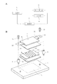
以下、添付図面を参照して本発明の好ましい実施例を説明する。図1(A)は、本発明の1実施例によるオゾン発生用モジュールのブロック図であり、図1(B)はオゾン発生用モジュールのオゾン発生部の分解斜視図である。
図1(A)に示すように、本発明のオゾン発生用モジュールは、オゾン発生部1と、オゾン発生部1に電力を供給する電源部2と、電源部2からオゾン発生部1への電力供給を制御する制御部3を備えている。制御部3は、予め決定された一定の時間間隔毎に、電源部2からオゾン発生部1への電力供給が予め決定された一定の時間継続してなされるように制御を行う。オゾン発生用モジュールは、また、オゾン発生部1への電力供給が行われていることを表示する表示部4を備えている。
Hereinafter, preferred embodiments of the present invention will be described with reference to the accompanying drawings. FIG. 1A is a block diagram of an ozone generation module according to one embodiment of the present invention, and FIG. 1B is an exploded perspective view of an ozone generation unit of the ozone generation module.
As shown in FIG. 1A, an ozone generation module according to the present invention includes an
次に図1(B)を参照して、オゾン発生部1は、焦電性結晶体5を備えている。焦電性結晶体5としては、例えば、タンタル酸リチウム(LiTaO3)やニオブ酸リチウム(LiNbO3)の単結晶が用いられる。この実施例では、焦電性結晶体5は、薄い矩形平板状を有しており、一面側が正の電気面、他面側が負の電気面を形成している。なお、焦電性結晶体5の形状はこの実施例に限定されず、任意の形状の焦電性結晶体が使用可能である。
Next, referring to FIG. 1 (B), the
オゾン発生部1は、また、焦電性結晶体5を加熱するためのヒーター6を備えている。
ヒーター6は、この実施例では、耐熱性の基板6a(焦電性結晶体5に対応する矩形平板状を有する)にヒーター回路6bが一定のパターンで(エッチング等により)設けられた、基板型ヒーターからなっている。なお、基板型ヒーターは、この実施例のものに限定されず、焦電性結晶体5に対応する矩形平板状のヒーターであればどのようなものでもよく、例えば、雲母板に電熱線を巻きつけたものを基板型ヒーターとして用いることもできる。
The
In this embodiment, the
そして、ヒートシンク7のヒーター固定面7aの全体にカプトン(登録商標)テープ8aが貼着され、次いで、ヒーター6が、ヒーター回路6bの設けられた面を上にした状態で、ヒーター固定面7a上に置かれる。
次に、ヒーター6の表面(ヒーター回路6bの設けられた面)に、別のカプトンテープ8bを介して、焦電性結晶体5が置かれる。この場合、焦電性結晶体5は、正の電気面および負の電気面のいずれを上にした状態で置かれても構わない。
Then, a Kapton (registered trademark)
Next, the
また、ヒートシンク7のヒーター固定面7aの長さ方向の両外側には、焦電性結晶体5の厚みにヒーター6の厚みを加えた高さのスペーサ9が突設されており、焦電性結晶体5の長さ方向両側に上方から板バネ10が重ねられ、この板バネ10がネジ11によってスペーサ9に固定される。この場合、板バネ10の焦電性結晶体5に接触する部分には、別のカプトンテープ8cが貼着されている。こうして、ヒーター6が、焦電性結晶体5とともに、板バネ10によってヒートシンク7のヒーター固定面7aに軽く押し付けられた状態でヒートシンク7に固定される。この状態で、ヒーター6およびヒートシンク7は、カプトンテープ8aおよび8cによって互いに電気的に絶縁され、ヒーター6および焦電性結晶体5は、カプトンテープ8bによって互いに電気的に絶縁されている。
In addition,
上記実施例では、基板型のヒーター6が、ヒートシンク7に電気絶縁された状態で取り付けられるとともに、焦電性結晶体5に電気絶縁された状態で接触する構成としたが、オゾン発生部におけるヒーターの構成およびヒーターの取付構造は、この実施例に限定されるものではない。
In the above embodiment, the
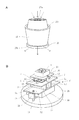
図2(A)は、本発明の別の実施例によるオゾン発生部の分解斜視図である。図2(A)中、図1に示したものと同じ構成要素には同一の番号を付し、詳細な説明を省略する。
図2(A)の実施例では、ヒーターとして、電熱線6’が焦電性結晶体5の長さ方向に沿ってコイル状に巻きつけられている。この場合、電熱線6’には、耐熱性および電気絶縁性を有する被覆がなされ、それによって、電熱線6’は、焦電性結晶体5に電気絶縁された状態で取り付けられかつ接触している。また、電熱線6’は、この実施例のように焦電性結晶体5の長さ方向に沿ってコイル状に巻きつけられていてもよいし、焦電性結晶体5の幅方向に沿ってコイル状に巻きつけられていてもよい。
FIG. 2A is an exploded perspective view of an ozone generator according to another embodiment of the present invention. 2A, the same components as those shown in FIG. 1 are denoted by the same reference numerals, and detailed description thereof is omitted.
In the embodiment of FIG. 2A, a
そして、ヒートシンク7における焦電性結晶体固定面12にカプトンテープ8a’が貼着され、焦電性結晶体5がカプトンテープ8a’を介して焦電性結晶体固定面12に置かれる。この場合、焦電性結晶体5は、正の電気面および負の電気面のいずれを上にした状態で置かれても構わない。
Then, the
また、ヒートシンク7の焦電性結晶体固定面12の長さ方向の両外側には、電熱線6’を巻きつけられた状態の焦電性結晶体5の厚みに対応する高さのスペーサ9が突設されており、焦電性結晶体5の長さ方向両側に上方から板バネ10が重ねられ、この板バネ10がネジ11によってスペーサ9に固定される。この場合、板バネ10の焦電性結晶体5に接触する部分には、カプトンテープ8cが貼着されている。こうして、焦電性結晶体5が、板バネ10によってヒートシンク7の焦電性結晶体固定面12に軽く押し付けられた状態でヒートシンク7に固定される。
Further,
ヒーター6、6’は、また、電源部2からの供給電圧と、焦電性結晶体5に対する予め決定された最適電流値(後述する)と、からオームの法則に従って算出された抵抗値を有している。
The
電源部2は、本発明によるオゾン発生モジュールが使用される環境に応じて、異なる構成をとり得る。例えば、家庭用コンセントが利用可能な場合には、オゾン発生用モジュールの電源部2は、家庭用コンセントに接続されるACアダプターを含んでいることが好ましく、また、モジュールが自動車に搭載される場合には、電源部2は、車載用バッテリーから電力を得るための、例えば、シガーライター用アダプターを含んでいることが好ましい。また別の実施例によれば、電源部2は、充電池等の電池から構成される。 The power supply unit 2 can take different configurations depending on the environment in which the ozone generation module according to the present invention is used. For example, when a household outlet is available, the power supply unit 2 of the ozone generating module preferably includes an AC adapter connected to the household outlet, and the module is mounted on an automobile. In addition, it is preferable that the power supply unit 2 includes, for example, a cigarette lighter adapter for obtaining power from the in-vehicle battery. Moreover, according to another Example, the power supply part 2 is comprised from batteries, such as a rechargeable battery.
制御部3は、PIC(Peripheral Interface Controller)等の、インターバル・タイマー機能を備えたワンチップマイコンからなっていることが好ましい。制御部3は、ヒーター6,6’に対し一定の時間間隔毎に一定の継続時間だけ電力供給がなされるように制御を行う。それによって、焦電性結晶体5の温度昇降が繰り返される。
表示部4は、必要に応じて備えられ、LEDから構成されていることが好ましい。
The
The
焦電性結晶体5に対する最適電流値は、予め決定された濃度(人体に悪影響を及ぼさずに、殺菌や脱臭ができる程度の濃度。好ましくは、0.01〜0.05ppm)のオゾンを発生させるべく、焦電性結晶体の最高温度が予め決定された範囲内(好ましくは、80℃〜90℃)に維持されつつ、予め決定された温度差の範囲内(好ましくは、40℃〜60℃)で焦電性結晶体5の温度昇降が繰り返されるような電流値として予め決定される。
The optimum current value for the
図3は、図1および図2(A)に示したオゾン発生用モジュールの回路図の1例を示したものである。なお、図3中、図1および図2(A)に示した構成要素と同じ構成要素には同一番号を付した。
図3(A)は、電源部2が、家庭用コンセントに接続されるACアダプター(DC12V用)、または自動車のシガーライター用アダプター(DC12V用)を含んでいる場合の回路を示しており、図3(B)は、電源部2が、家庭用コンセントに接続されるACアダプター(DC9V用)および充電池(DC6V)を含んでいる場合の回路を示している。
FIG. 3 shows an example of a circuit diagram of the ozone generation module shown in FIGS. 1 and 2A. In FIG. 3, the same components as those shown in FIG. 1 and FIG.
FIG. 3A shows a circuit in the case where the power supply unit 2 includes an AC adapter (for DC12V) connected to a household outlet or a car cigarette lighter adapter (for DC12V). 3 (B) shows a circuit when the power supply unit 2 includes an AC adapter (for DC 9V) and a rechargeable battery (DC 6V) connected to a household outlet.
図3(A)を参照して、この実施例では、ACアダプターまたはシガーライター用アダプター(いずれも図示しない)のプラグが接続されるジャック18が備えられ、このジャック18には、電源スイッチ22およびダイオード23を介して3端子レギュレータ17の入力端子17aが接続されている。3端子レギュレータ17は電源部2の一部をなしている。
Referring to FIG. 3A, in this embodiment, a
制御部3はPICから構成され、PIC3の電圧入力端子3aが3端子レギュレータ17の出力端子17bに接続されている。3端子レギュレータ17のグラウンド端子17cおよびPIC3のグラウンド端子3bは接地されている。
また、ヒーター6、6’が、ダイオード23および3端子レギュレータ17の入力端子17a間と、PIC3の電流出力端子3cとの間に接続されている。さらに、表示部4は、互いに直列接続されたLED20および抵抗21から構成され、ヒーター6、6’に並列接続されている。
The
PIC3は、タイムインターバル機能を有しており、タイマーの作動時間を切り替えるためのタイマー設定スイッチ3dを備えている。この実施例では、タイマー設定スイッチ3dによって、電流出力端子3cからヒーター6、6’への電流供給の継続時間と停止時間を、3つのパターン(電力供給1分および電力供給停止3分の繰り返し;電力供給2分および電力供給停止6分の繰り返し;電力供給3分および電力供給停止10分の繰り返し)で設定可能になっている。
The
こうして、ACアダプターまたはシガーライター用アダプターのプラグがジャック18に接続された後、ACアダプターが家庭用コンセントに接続され、またはシガーライター用アダプターがシガーライターソケットに挿入される。そして、電源スイッチ22がONにされると、ヒーター6、6’に対し、所定の時間間隔毎に所定の継続時間だけ電力が供給される。この場合、ヒーター6、6’に電力供給がなされている間だけLED20が点灯する。
Thus, after the plug of the AC adapter or cigarette lighter adapter is connected to the
図3(B)に示した実施例は、図3(A)の実施例と、ジャック18から3端子レギュレータ17の入力端子17aまでの回路構成が異なるだけである。よって、図3(B)中、図3(A)に示したものと同一の構成要素には同一番号を付し、以下ではその詳細な説明を省略する。
The embodiment shown in FIG. 3B differs from the embodiment shown in FIG. 3A only in the circuit configuration from the
図3(B)を参照して、この実施例では、ジャック18に、ダイオード23、抵抗24およびダイオード25を介して3端子レギュレータ17の入力端子17aが接続されている。また、抵抗24およびダイオード25間に充電池19の+端子が接続され、充電池19の−端子は、3端子レギュレータ17のグラウンド端子17cおよびPIC3のグラウンド端子3bとともに接地されている。また、ヒーター6、6’が抵抗およびダイオード25間に接続されている。
3B, in this embodiment, the
この実施例では、ジャック18にACアダプター(図示はしない)のプラグが接続されると、充電池19に充電がなされると同時に、このACアダプターから電力供給がなされる一方、ジャック18にACアダプターのプラグが接続されないときは、充電池19から電力供給がなされる。
In this embodiment, when a plug of an AC adapter (not shown) is connected to the
次に、このモジュールのオゾン発生動作について説明する。
焦電性結晶体5は、定常状態において電気的に分極していて(一面が正の電気面を、他面が負の電気面をなす)、その電気量と等量で異なる符号の電荷が結晶体表面に吸着しているため、常時は電気的に中性である。
そして、電源部2からオゾン発生部1に電力供給が行われると、オゾン発生部1のヒーター6、6’が発熱し、それによって、焦電性結晶体5が加熱される。
Next, the ozone generation operation of this module will be described.
The
When power is supplied from the power supply unit 2 to the
焦電性結晶体5の温度が上昇すると、結晶体5の自発分極は小さくなり、負の電気面では負の電荷の表面電荷密度が減少するが、負の電気面に吸着している正の電荷量はすぐには減少しない。その結果、負の電気面は正に帯電する。同様にして、正の電気面は負に帯電する。それによって、結晶体5の内部および外部に、負の電気面から正の電気面に向かう強電界が発生する。
When the temperature of the
この強電界によって結晶体5の周辺の気体の一部が電離し、遊離電子が結晶体5に衝突して、その静電エネルギー(運動エネルギーに転化する)の大きさに応じた波長の連続X線および結晶体元素の特性X線が発生する。本発明においては、結晶体5の外部空間は大気圧であり、遊離電子の平均自由行程は短く、強電界であっても遊離電子は十分に加速されないので、発生するX線の波長は非常に長く、その大部分が軟X線となる。
Due to this strong electric field, a part of the gas around the
この軟X線が大気中の酸素分子に吸収されて酸素分子が解離し、励起された単原子が発生し、これが他の酸素イオンと会合してオゾンを発生する。この場合、一般に酸素による光子の吸収は紫外線波長で大きいが、軟X線の光子はさらに大きいエネルギーをもっており、軟X線光子1個で複数の酸素分子を励起解離させるので、この軟X線によってオゾン生成効率が上がり、高濃度のオゾンを発生させることができる。なお、大気圧中では、軟X線のエネルギーは急速に吸収されるので、軟X線の発生領域は、結晶体5の付近に限定される。
The soft X-rays are absorbed by oxygen molecules in the atmosphere and the oxygen molecules are dissociated to generate excited single atoms, which associate with other oxygen ions to generate ozone. In this case, absorption of photons by oxygen is generally large at the ultraviolet wavelength, but photons of soft X-rays have a larger energy, and a single soft X-ray photon excites and dissociates a plurality of oxygen molecules. Ozone generation efficiency is increased and high concentration ozone can be generated. In addition, since the energy of soft X-rays is rapidly absorbed under atmospheric pressure, the soft X-ray generation region is limited to the vicinity of the
また、結晶体5から生じた強電界によっても、大気中の酸素分子が解離し、励起された単原子が大気中に発生する。そして、この酸素の単原子が他の酸素分子と会合しオゾンを発生する。
Also, due to the strong electric field generated from the
次に、電源部2からオゾン発生部1への電力供給が停止されると、オゾン発生部1のヒーター6、6’の発熱が停止すると同時に、ヒートシンク7が機能して焦電性結晶体5が冷却される。
Next, when the power supply from the power supply unit 2 to the
焦電性結晶体5の温度が下降すると、結晶体5の自発分極が大きくなって、負の電気面では負の電荷の表面電荷密度が増大し、負の電気面は負に帯電する。同様にして、正の電気面は正に帯電する。その結果、結晶体5の内部および外部に、正の電気面から負の電気面に向かう電界が発生する。
When the temperature of the
この電界によって、結晶体5の温度上昇時と同様、結晶体5の周辺の大気中の気体分子の一部が電離し、遊離電子が結晶体5に衝突して軟X線が発生する。そして、この軟X線が大気中の酸素分子に吸収されて酸素分子が解離し、励起された単原子が発生し、これが他の酸素イオンと会合してオゾンを発生する。
また、結晶体5から生じた電界によっても、大気中の酸素分子が解離し、励起された単原子が大気中に発生する。そして、この酸素の単原子が他の酸素分子と会合しオゾンを発生する。
As in the case of the temperature rise of the
Also, the electric field generated from the
こうして、焦電性結晶体に対し、一定の時間間隔毎に一定の継続時間だけ最適電流値が適用され、それによって、焦電性結晶体の温度昇降が、その最高温度が予め決定された範囲内(好ましくは、80°〜90℃)に維持され、かつ予め決定された温度差の範囲内(好ましくは、40℃〜60℃)で繰り返され、その結果、予め決定された濃度(人体に悪影響を及ぼさずに、殺菌や脱臭ができる程度の濃度。好ましくは、0.01〜0.05ppm)のオゾンが発生する。 In this way, the optimum current value is applied to the pyroelectric crystal body for a certain duration every certain time interval, whereby the temperature rise and fall of the pyroelectric crystal body is a range in which the maximum temperature is determined in advance. Within a range (preferably 80 ° to 90 ° C.) and repeated within a predetermined temperature difference range (preferably 40 ° C. to 60 ° C.), resulting in a predetermined concentration (in human body) The concentration is such that it can be sterilized and deodorized without adverse effects (preferably 0.01 to 0.05 ppm).
なお、オゾン発生部1を図1(A)および図1(B)に示すような構成とした場合には、焦電性結晶体5の温度上昇がヒーター6、6’による加熱によってなされるのに対し、焦電性結晶体5の温度下降は、専ら、ヒートシンク7からの放熱に頼っており、焦電性結晶体5を積極的に冷却する手段が備えられていない。そのため、使用する焦電性結晶体のサイズ等によっては、焦電性結晶体5の温度を所定の温度まで下降させるのに時間がかかり、オゾンの発生効率があまり良くない場合がある。
When the
このような場合には、オゾン発生部1に冷却手段としてファンを備えていることが好ましい。図2(B)は、図1(B)のオゾン発生部1にファンを備えた場合の構成例を示した斜視図である。なお、図2(B)中、図1(B)に示したものと同じ構成要素には同一番号を付し、以下においてその詳細な説明を省略する。
図2(B)を参照して、この実施例では、ヒートシンク7の上面における焦電性結晶体5の幅方向両外側に、一対のスペーサ15が突設されている。そして、スペーサ15の上端には、ファン固定板13がネジ16によって固定され、焦電性結晶体5の上方においてこれに対向して配置されている。ファン固定板13の中央には円形開口(図示はしない)が形成されており、ファン固定板13上に、ファン14が、その送風口を円形開口に整合させた状態で取り付けられている。
In such a case, the
With reference to FIG. 2 (B), in this embodiment, a pair of
この実施例によれば、焦電性結晶体5の温度下降時、ヒーター6による加熱が停止したときに、ヒートシンク7から放熱されると同時に、焦電性結晶体5がファン14によって空冷されるので、短時間のうちに、焦電性結晶体5の温度が所定の温度まで下降し、オゾンの発生効率が上がる。
加えて、ファン14を常時作動させておくことにより、オゾン発生部1で発生したオゾンをファン14からの送風によって素早くかつ一様に周辺に拡散させることができる。
According to this embodiment, when the
In addition, by always operating the
本発明のオゾン発生用モジュールを用いれば、小型低消費電力型の空気清浄器を簡単に製造することができる。
図4は、オゾン発生部が図2(B)に示した構成のオゾン発生用モジュールを備えた卓上型空気清浄器の斜視図であり、図4(B)は当該卓上型空気清浄器のカバーが取り外された状態の斜視図である。図4の実施例では、オゾン発生用モジュールは、図2(B)に示したものとほぼ同じ構成のオゾン発生部を有し、また、図3(B)に示したものとほぼ同じ回路構成を有している。よって、図4中、図2(B)および図3(B)に示したものと同じ構成要素には同一番号を付し、以下ではその詳細な説明を省略する。
If the ozone generating module of the present invention is used, a small and low power consumption type air purifier can be easily manufactured.
FIG. 4 is a perspective view of a desktop air cleaner in which the ozone generating unit includes the ozone generating module having the configuration shown in FIG. 2B, and FIG. 4B is a cover of the desktop air cleaner. It is a perspective view in the state where was removed. In the embodiment of FIG. 4, the ozone generation module has an ozone generation unit having substantially the same configuration as that shown in FIG. 2B, and has almost the same circuit configuration as that shown in FIG. 3B. have. Therefore, in FIG. 4, the same components as those shown in FIGS. 2B and 3B are denoted by the same reference numerals, and detailed description thereof will be omitted below.
図4を参照して、卓上型空気清浄器は、円盤状のベース26と、一端が開口した実質上筒状のカバー27を備えている。カバー27が、その開口を下向きにし、かつ下端縁がベース26の上面から間隔をあけた状態で取り付けられ(カバー27の取付構造は後述する)、カバー27の下端縁とベース26の上面との間に空気放出口27bが形成されている。カバー27の上端面には複数の貫通孔が設けられ、空気取入口27aが形成されている。
Referring to FIG. 4, the desktop air cleaner includes a disk-shaped
ベース26上には一対のスペーサ31が突設され、スペーサ31には、電気回路収容ボックス30が、上下からコ字状断面の部材29および固定板28によって挟まれた状態で、ネジ32によって固定されている。電気回路収容ボックス30は、オゾンによって酸化されにくいテフロン(登録商標)等のフッ素樹脂から形成され、内部に、オゾン発生用モジュールのPIC3、3端子レギュレータ17、充電池19およびダイオード25(図3(B))等が収容される。
A pair of
この実施例では、オゾン発生部1’のヒートシンク7の下面に、その拡張部分として、一対の脚7aが取り付けられるとともに、ファン固定板13をヒートシンク7に固定するためのスペーサ15’が、ヒートシンク7を貫通し、ヒートシンク7から下方に脚7aと同じ長さのび、固定板28に突設されている。
In this embodiment, a pair of
こうして、ヒートシンク7および固定板28間に適当な間隙を設けたことにより、ヒートシンク7による放熱効率が上がると同時に、電気回路収容ボックス30の過剰加熱が防止される。
また、ファン固定板13、ヒートシンク7および固定板28は、それらがピラミッド状をなすようなサイズに形成されている。
Thus, by providing an appropriate gap between the
The
図示はしないが、LED20は、その発光部が空気放出口27bから露出するように配置され、ACアダプターのプラグを接続するためのジャック18は、卓上型空気清浄器の外部に配置される。
また、カバー27は、小径の上部と大径の下部が段差部分27cで接続された形状を有し、カバー27は、この段差部分27の内側壁面が、ファン固定板13の上面周縁に当接することによって、ベース26に取り付けられるようになっている。
Although not shown, the
The
こうして、充電池19が十分に充電されている場合には、充電池19からの電力供給を受けて、オゾン発生用モジュール1’が動作する。そして、ファン14によって、空気取入口27aから、外部の空気が取り入れられ、空気取入口27aからオゾン発生部1’を経て空気放出口27bに向けて気流が常時生じるとともに、オゾン発生部1’の焦電性結晶体5の温度昇降が繰り返される。それによって、空気放出口27bから、予め決定された濃度のオゾンが常時放出される。
充電池19が消耗した場合には、ジャック18にACアダプターのプラグが接続され、ACアダプターからの電力供給を受けて充電池19が充電されるとともに、卓上型空気清浄器が動作する。
In this way, when the
When the
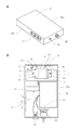
図5は、本発明によるオゾン発生用モジュールを備えた車載型空気清浄器を示す図であり、(A)は斜視図であり、(B)は上蓋が取り外された状態の平面図である。
図5の実施例では、オゾン発生用モジュールは、図1(B)に示したオゾン発生部を有し、また、図3(A)に示したものとほぼ同じ回路構成を有している。よって、図5中、図1(B)および図3(A)に示したものと同じ構成要素には同一番号を付し、以下ではその詳細な説明を省略する。
FIG. 5 is a view showing an in-vehicle air cleaner provided with an ozone generation module according to the present invention, in which (A) is a perspective view and (B) is a plan view with a top cover removed.
In the embodiment of FIG. 5, the ozone generating module has the ozone generating section shown in FIG. 1 (B) and has almost the same circuit configuration as that shown in FIG. 3 (A). Therefore, in FIG. 5, the same components as those shown in FIGS. 1B and 3A are denoted by the same reference numerals, and detailed description thereof will be omitted below.
図5を参照して、車載型空気清浄器は、上端面が開口した扁平箱型のケーシング本体33aと、ケーシング本体33aの上端面開口を封閉し得る上蓋33bとからなるケーシング33を備えている。
Referring to FIG. 5, the vehicle-mounted air cleaner includes a casing 33 including a flat box type casing
ケーシング本体33aの長手方向の一側面には空気入口34が設けられ、当該一側面に直交する一対の側面のうちの一方には、空気出口35が設けられている。空気入口34および空気出口35にはメッシュが取り付けられている。ケーシング本体33aの内部であって、空気出口35の付近には、本発明によるオゾン発生用モジュールのオゾン発生部1が取り付けられている。
An
ケーシング本体33aの内部であって、空気入口34が設けられた側面に対向する側面側には、電気回路収容ボックス30が設けられている。電気回路収容ボックス30は、オゾンによって酸化されにくいテフロン(登録商標)等のフッ素樹脂から形成され、内部に、PIC3および3端子レギュレータ17(図3(A))が収容されている。
An electric
ケーシング本体33aの空気出口35が設けられた側面に対向する側面には、シガーライター用アダプターを接続するためのジャック18、および電源スイッチ22(図3(A))が取り付けられている。また、ケーシング本体33aの空気出口35が設けられた側面には、LED20(図3(A))が取り付けられている。
A
さらに、ケーシング本体33aの内部であって、オゾン発生部1と空気入口34との間のスペースには、ファン14が、その送風口を空気出口35およびオゾン発生部1に向けて配置されている。回路図は図示しないが、ファン14は、電源スイッチ22のON/OFFによって、作動状態および非作動状態が切り替えられるようになっている。
Further, in the space between the
こうして、シガーライター用アダプターのプラグがジャック18に接続された後、シガーライター用アダプターがシガーライターソケットに挿入される。次いで、電源スイッチ22がONにされると、ファン14によって、空気入口34から外部の空気が取り入れられて、空気入口34からオゾン発生部1を経て空気出口35に向けて気流が常時生じるとともに、オゾン発生部1の焦電性結晶体5の温度昇降が繰り返される。それによって、空気出口35から外部に、予め決定された濃度のオゾンが常時放出される。
Thus, after the plug of the cigarette lighter adapter is connected to the
本発明によるオゾン発生用モジュールは、簡単かつコンパクトな構成を有しているので、屋内用照明器具や家電製品等に組み込むことによって、空気清浄器の機能を備えた屋内用照明器具および家電製品等を容易に製造することができる。 Since the ozone generating module according to the present invention has a simple and compact configuration, it is incorporated into an indoor lighting device, a home appliance, or the like, so that the indoor lighting device and the home appliance with a function of an air purifier are provided. Can be easily manufactured.
1、1’ オゾン発生部
2 電源部
3 制御部(PIC)
3a 電圧入力端子
3b グラウンド端子
3c 電流出力端子
3d タイマー設定スイッチ
4 表示部
5 焦電性結晶体
6 ヒーター
6’ 電熱線
6a 基板
6b ヒーター回路
7 ヒートシンク
7a ヒーター固定面
8a、8a’、8b、8c カプトンテープ
9 スペーサ
10 板バネ
11 ネジ
12 焦電性結晶体固定面
13 ヒーター固定板
14 ファン
15 スペーサ
16 ネジ
17 3端子レギュレータ
17a 入力端子
17b 出力端子
17c グラウンド端子
18 ジャック
19 充電池
20 LED
21 抵抗
22 電源スイッチ
23 ダイオード
24 抵抗
25 ダイオード
26 ベース
27 カバー
27a 空気取入口
27b 空気放出口
27c 段差部分
28 固定板
29 コ字状断面の部材
30 電気回路収容ボックス
31 スペーサ
32 ネジ
33 ケーシング
33a ケーシング本体
33b 上蓋
34 空気入口
35 空気出口
1, 1 ′ Ozone generator 2
3a
21
Claims (2)
前記オゾン発生部は、
少なくとも1つの焦電性結晶体と、
前記焦電性結晶体が電気絶縁された状態で取り付けられたヒートシンクと、
前記ヒートシンクに支持部材を介して取り付けられ、前記焦電結晶体の上方において前記焦電結晶体に対向して配置されたファンと、
前記焦電性結晶体または前記ヒートシンクに電気絶縁された状態で取り付けられ、前記焦電性結晶体に電気絶縁された状態で接触するヒーターと、を有し、
前記ヒーターが、前記電源部からの供給電圧と、前記焦電性結晶体に対する予め決定された最適電流値と、からオームの法則に従って算出された抵抗値を有しており、
前記ファンによって前記焦電結晶体に吹き付ける前記大気の流れが形成されるとともに、前記ヒーターに対し一定の時間間隔ごとに一定の継続時間だけ前記電力供給がなされることによって前記焦電性結晶体の温度昇降が繰り返され、前記大気の流れ中の酸素分子が前記焦電結晶体から発生したX線および電界によりオゾン化されるようになっており、
前記焦電性結晶体に対する前記最適電流値は、予め決定された濃度のオゾンを発生させるべく、前記焦電性結晶体の最高温度が予め決定された範囲内に維持されつつ、予め決定された温度差の範囲内で前記焦電性結晶体の温度昇降が繰り返されるような電流値として予め決定されていることを特徴とするオゾン発生用モジュール。 Together are placed in the atmosphere, e Bei an ozone generator, and the ozone generator power unit for supplying power to, and a control unit for controlling the power supply by the power supply unit,
The ozone generator is
At least one pyroelectric crystal;
A heat sink attached in a state where the pyroelectric crystal body is electrically insulated;
A fan attached to the heat sink via a support member, and disposed above the pyroelectric crystal so as to face the pyroelectric crystal;
A heater that is attached in an electrically insulated state to the pyroelectric crystal body or the heat sink, and that contacts the pyroelectric crystal body in an electrically insulated state; and
The heater has a resistance value calculated according to Ohm's law from a supply voltage from the power supply unit and a predetermined optimum current value for the pyroelectric crystal,
A flow of the atmosphere blown to the pyroelectric crystal by the fan is formed, and the power is supplied to the heater for a certain duration every certain time interval, whereby the pyroelectric crystal The temperature rise and fall is repeated, and oxygen molecules in the atmospheric flow are ozonized by X-rays and electric fields generated from the pyroelectric crystals,
The optimal current value for the pyroelectric crystal is predetermined while maintaining the maximum temperature of the pyroelectric crystal within a predetermined range to generate ozone of a predetermined concentration. An ozone generating module, wherein the module is previously determined as a current value such that temperature rise and fall of the pyroelectric crystal is repeated within a temperature difference range.
Priority Applications (1)
| Application Number | Priority Date | Filing Date | Title |
|---|---|---|---|
| JP2012254108A JP6263786B2 (en) | 2012-11-20 | 2012-11-20 | Ozone generation module |
Applications Claiming Priority (1)
| Application Number | Priority Date | Filing Date | Title |
|---|---|---|---|
| JP2012254108A JP6263786B2 (en) | 2012-11-20 | 2012-11-20 | Ozone generation module |
Publications (2)
| Publication Number | Publication Date |
|---|---|
| JP2014101250A JP2014101250A (en) | 2014-06-05 |
| JP6263786B2 true JP6263786B2 (en) | 2018-01-24 |
Family
ID=51024116
Family Applications (1)
| Application Number | Title | Priority Date | Filing Date |
|---|---|---|---|
| JP2012254108A Active JP6263786B2 (en) | 2012-11-20 | 2012-11-20 | Ozone generation module |
Country Status (1)
| Country | Link |
|---|---|
| JP (1) | JP6263786B2 (en) |
Families Citing this family (1)
| Publication number | Priority date | Publication date | Assignee | Title |
|---|---|---|---|---|
| JP6367884B2 (en) * | 2016-09-30 | 2018-08-01 | 巨煬股▲ふん▼有限公司 | Ozone generator |
Family Cites Families (9)
| Publication number | Priority date | Publication date | Assignee | Title |
|---|---|---|---|---|
| US3840748A (en) * | 1973-06-04 | 1974-10-08 | Bendix Corp | Electron and x-ray generator |
| JPS54135692A (en) * | 1978-04-12 | 1979-10-22 | Senichi Masuda | Ozonizer |
| JPH057722A (en) * | 1991-07-02 | 1993-01-19 | Matsushita Electric Ind Co Ltd | Control method for adsorbent regeneration device |
| KR100317977B1 (en) * | 2000-01-21 | 2001-12-22 | 조 수 환 | Ozonied-water generating appartus |
| JP4593147B2 (en) * | 2004-03-30 | 2010-12-08 | 国立大学法人京都大学 | Ozone generation method and ozone generator |
| US7741615B2 (en) * | 2004-05-19 | 2010-06-22 | The Regents Of The University Of California | High energy crystal generators and their applications |
| JP3874361B2 (en) * | 2005-05-25 | 2007-01-31 | 国立大学法人京都大学 | Ozone generation method and apparatus using heteropolar crystal |
| JP5441038B2 (en) * | 2010-03-24 | 2014-03-12 | 学校法人同志社 | X-ray generator using heteropolar crystal |
| WO2012091709A1 (en) * | 2010-12-30 | 2012-07-05 | Utc Fire & Security Corporation | Ionization device |
-
2012
- 2012-11-20 JP JP2012254108A patent/JP6263786B2/en active Active
Also Published As
| Publication number | Publication date |
|---|---|
| JP2014101250A (en) | 2014-06-05 |
Similar Documents
| Publication | Publication Date | Title |
|---|---|---|
| US20150123540A1 (en) | Device for providing a flow of plasma | |
| CN102150334A (en) | Bi-polar ionization tube base and tube socket | |
| CN102714400A (en) | Portable ion generator | |
| CN102962132A (en) | Electrostatic precipitator with collection charge plates divided into electrically isolated banks | |
| CN102962133A (en) | Electrostatic precipitator cell with removable corona unit | |
| CN107530459B (en) | Sterilization box | |
| US20100039746A1 (en) | Portable air ionizer, interface for a portable ionizer, and method of advertising therewith | |
| CN113915697A (en) | Air conditioning system, fan module, air conditioning module and air conditioning device | |
| JP6263786B2 (en) | Ozone generation module | |
| US10985536B2 (en) | Portable air ionizer | |
| CN201832180U (en) | Electrostatic surface cleaning sterilizing tool | |
| JP6401020B2 (en) | Ion generator | |
| US7230215B2 (en) | Heat generating device formed of heat generating diaphragm plates | |
| CN113847676A (en) | Nanometer water ion air purifier | |
| JP2003100419A (en) | Ion generator and air conditioner | |
| JP5030010B2 (en) | UV irradiation equipment | |
| WO2015002607A1 (en) | Interactive ionizers and methods for providing ions | |
| CN105749423B (en) | For injecting ions into the device and method of air stream | |
| JP6631873B2 (en) | Shoe cleaner | |
| CN112855579B (en) | Fan with purification function | |
| JPH0725602A (en) | Ozone-generating device | |
| HK1226345B (en) | Device and method for injecting ions into a stream of air | |
| JP2004159753A (en) | Ion generator | |
| EP3041095A1 (en) | Device for injecting ions into a stream of air | |
| KR20230074866A (en) | An Ion Generating Device for a Lighting Device and the Lighting Device with the Same |
Legal Events
| Date | Code | Title | Description |
|---|---|---|---|
| A621 | Written request for application examination |
Free format text: JAPANESE INTERMEDIATE CODE: A621 Effective date: 20151120 |
|
| A521 | Request for written amendment filed |
Free format text: JAPANESE INTERMEDIATE CODE: A523 Effective date: 20151201 |
|
| A977 | Report on retrieval |
Free format text: JAPANESE INTERMEDIATE CODE: A971007 Effective date: 20160818 |
|
| A131 | Notification of reasons for refusal |
Free format text: JAPANESE INTERMEDIATE CODE: A131 Effective date: 20160921 |
|
| A521 | Request for written amendment filed |
Free format text: JAPANESE INTERMEDIATE CODE: A523 Effective date: 20161115 |
|
| A711 | Notification of change in applicant |
Free format text: JAPANESE INTERMEDIATE CODE: A711 Effective date: 20161222 |
|
| A521 | Request for written amendment filed |
Free format text: JAPANESE INTERMEDIATE CODE: A821 Effective date: 20161222 |
|
| A02 | Decision of refusal |
Free format text: JAPANESE INTERMEDIATE CODE: A02 Effective date: 20170510 |
|
| A521 | Request for written amendment filed |
Free format text: JAPANESE INTERMEDIATE CODE: A523 Effective date: 20170807 |
|
| A521 | Request for written amendment filed |
Free format text: JAPANESE INTERMEDIATE CODE: A821 Effective date: 20170810 |
|
| A911 | Transfer to examiner for re-examination before appeal (zenchi) |
Free format text: JAPANESE INTERMEDIATE CODE: A911 Effective date: 20170901 |
|
| TRDD | Decision of grant or rejection written | ||
| A01 | Written decision to grant a patent or to grant a registration (utility model) |
Free format text: JAPANESE INTERMEDIATE CODE: A01 Effective date: 20171108 |
|
| A711 | Notification of change in applicant |
Free format text: JAPANESE INTERMEDIATE CODE: A711 Effective date: 20171129 |
|
| A61 | First payment of annual fees (during grant procedure) |
Free format text: JAPANESE INTERMEDIATE CODE: A61 Effective date: 20171129 |
|
| A521 | Request for written amendment filed |
Free format text: JAPANESE INTERMEDIATE CODE: A821 Effective date: 20171129 |
|
| R150 | Certificate of patent or registration of utility model |
Ref document number: 6263786 Country of ref document: JP Free format text: JAPANESE INTERMEDIATE CODE: R150 |
|
| R250 | Receipt of annual fees |
Free format text: JAPANESE INTERMEDIATE CODE: R250 |
|
| R250 | Receipt of annual fees |
Free format text: JAPANESE INTERMEDIATE CODE: R250 |
|
| R250 | Receipt of annual fees |
Free format text: JAPANESE INTERMEDIATE CODE: R250 |
|
| R250 | Receipt of annual fees |
Free format text: JAPANESE INTERMEDIATE CODE: R250 |
|
| R250 | Receipt of annual fees |
Free format text: JAPANESE INTERMEDIATE CODE: R250 |
|
| R250 | Receipt of annual fees |
Free format text: JAPANESE INTERMEDIATE CODE: R250 |