JP6263735B2 - Electric dust filter unit with cotton filter - Google Patents
Electric dust filter unit with cotton filter Download PDFInfo
- Publication number
- JP6263735B2 JP6263735B2 JP2013230023A JP2013230023A JP6263735B2 JP 6263735 B2 JP6263735 B2 JP 6263735B2 JP 2013230023 A JP2013230023 A JP 2013230023A JP 2013230023 A JP2013230023 A JP 2013230023A JP 6263735 B2 JP6263735 B2 JP 6263735B2
- Authority
- JP
- Japan
- Prior art keywords
- air
- filter
- charged
- fiber
- conductor
- Prior art date
- Legal status (The legal status is an assumption and is not a legal conclusion. Google has not performed a legal analysis and makes no representation as to the accuracy of the status listed.)
- Active
Links
Images


Landscapes
- Electrostatic Separation (AREA)
Description
本発明は、空気中の大気塵を除去する空気清浄用フィルタに関するものである。 The present invention relates to an air cleaning filter that removes atmospheric dust in the air.
(従来技術1)
大気塵を除去して空気を清浄にする空気清浄装置として、図10に示すような2段式電気集塵機が従来から一般的に知られている。以下、その2段式電気集塵機について説明する。
(Prior art 1)
A two-stage electrostatic precipitator as shown in FIG. 10 is generally known as an air cleaning device that removes atmospheric dust and cleans the air. Hereinafter, the two-stage electrostatic precipitator will be described.
従来の2段式電気集塵機は図10に示すように上流側から順に帯電部101、集塵部104で構成されている。
As shown in FIG. 10, the conventional two-stage electrostatic precipitator includes a
帯電部101は線状の放電電極102とそれを挟むように設けられた帯電部アース電極板103とで構成される。放電電極102には高圧電源107によって高電圧が印加され、帯電部アース電極板103にはアースが接続されて0Vとなっており、両者の間でコロナ放電が発生する。
The
集塵部104は高圧電極板105および集塵部アース電極板106とで構成される。高圧電極板105と集塵部アース電極板106は一定の間隔を開けて空間を設けながら交互に積層されている。高圧電極板105には高圧電源107によって高電圧が印加され、集塵部アース電極板にはアースが接続されて0Vとなっており、両者の間に作られた空間には電場が設けられている。
The
通風方向108に沿って空気は2段式電気集塵機に取り込まれ、その空気中に含まれる大気塵は帯電部101においてコロナ放電で発生した空気イオンと衝突して帯電する。帯電した大気塵は下流側にある集塵部104に送り込まれ、高圧電極板105と集塵部アース電極板106の間に作られた空間を通過する。そして空間に設けられた電場によってクーロン力を受け、移動する。図10のように放電電極102および高圧電極板106にそれぞれ正極の高電圧が印加されている場合、大気塵は正に帯電し、正に帯電した大気塵は高圧電極板105から集塵部アース電極板106へと移動して集塵部アース電極板106に付着し、空気中から除去される。
Air is taken into the two-stage electrostatic precipitator along the
(従来技術2)
また、別の集塵装置として、特許文献1に記載の空気清浄装置がある。以下、図11を用いてこの空気清浄装置を説明する。図11に記載の空気清浄装置は上流側から順に帯電部101、誘電濾材109で構成される。帯電部101は先の(従来技術1)に記載のものと同じで、通過した大気塵をコロナ放電によって帯電させる。誘電濾材109は誘電繊維109aと導電繊維109bとを混紡してシート化されたものであり、また、アースに接続されている。そして高電圧が印加された放電電極102と導電繊維109bとの間に電場が設けられ、その電場の中に存在する誘電繊維109aは誘電分極して電荷が誘起される。
(Prior art 2)
Moreover, there exists an air purifying apparatus of
通風方向108に沿って帯電部101を通過した空気中の大気塵は帯電し、帯電した大気塵は電場によって電荷が誘起された誘電繊維109aによって吸着捕集される。
The atmospheric dust in the air that has passed through the
(従来技術3)
また、別の集塵装置として、特許文献2に記載のフィルタがある。以下、図12を用いてこのフィルタを説明する。支持板111に無数の帯電繊維110が固定された帯電繊維集合体112が形成される。隣接する帯電繊維110どうしの間には帯電繊維が有する電荷によって電場が設けられている。そして通気性を有する段ボール状の中空スペーサー113と帯電繊維集合体112とを交互に4つずつ積層したものを仕切り板114で仕切りながらフィルタケース115に納めた構造となっている。
(Prior art 3)
Moreover, there exists a filter of
そして通風方向108に沿って空気はフィルタに取り込まれ、空気中の大気塵は帯電繊維110どうしの作る電場によって吸着捕集される。
Air is taken into the filter along the
従来技術1に記載の2段式電気集塵機は、集塵部を作るために多数の高圧電極板と集塵部アース電極板を一定の間隔を開けながら交互に積層しなくてはいけないため、構造が複雑で作るのが大変難しい。また、高圧電極板には高電圧が印加されるため、安全のために人が触れないようにしたり、また、集塵部アース電極板やケースフレームとの間で短絡が起きないようにしなくてはならず、簡単に作ることができない。
The two-stage electrostatic precipitator described in Prior
また、従来技術2に記載の空気清浄装置は誘電濾材に高電圧を印加する必要がなく比較的簡単に作れるが、シート状のため通風方向が濾材に対して垂直になり、捕集した大気塵は濾材の上に堆積して通風に必要な隙間を埋めてしまう。そのため目詰まりが早く起こってしまい、通風量が短期間で減ってしまう。
In addition, the air cleaning device described in the
また、通風方向に対して垂直な平面状の電場が1面のみ作られた構造であるため、通風方向に奥行きのある電場がなく、高い集塵性能が得られない。 In addition, since it has a structure in which only one planar electric field perpendicular to the ventilation direction is created, there is no electric field having a depth in the ventilation direction, and high dust collection performance cannot be obtained.
また、混紡するには短い誘電繊維と短い導電繊維を溶液中に混ぜて紙を漉くように作るのが現実的だが、短い導電繊維を用いて混紡すると導電繊維どうしを接触させて導通させることが難しく、誘電濾材をアースに接続して0Vにすることが容易にできない。 In order to blend, it is realistic to mix a short dielectric fiber and a short conductive fiber in a solution so as to spread the paper. However, if a short conductive fiber is used for blending, the conductive fibers can be brought into contact with each other to conduct electricity. Difficult, it is not easy to connect the dielectric filter media to ground and make it 0V.
また、従来技術3記載のフィルタは帯電繊維どうしの電位差が明確でなく、帯電繊維どうしが作る電場が強くない。そのため高い集塵性能が得られない。また、大気塵を捕集していくうちに帯電繊維の帯電が落ちてしまい、集塵性能が徐々に下がってしまう。
Further, in the filter described in Prior
そこで本発明は、上記従来の課題を解決するものであり、簡単かつ大量に作成でき、長期間において目詰まりせず、高い集塵性能を保つことが可能な電気集塵フィルタユニットの提供を目的とする。 SUMMARY OF THE INVENTION The present invention solves the above-described conventional problems, and an object thereof is to provide an electric dust collection filter unit that can be produced easily and in large quantities, is not clogged for a long period of time, and can maintain high dust collection performance. And
上記課題を解決するために、本発明の電機集塵フィルタユニットは、上流側に空気をイオン化するイオン化手段と、下流側にフィルタ部とを備え、一様に混在する帯電繊維と導電繊維とを通風方向に対して綿状に積層して構成される綿状濾過体を、底部もしくは上部に格子状導電体を備えたフィルタケースに収め、導電繊維と格子状導電体とを接触導通させることでフィルタ部は構成され、格子状導電体を通じて導電繊維をアースに接続することにより初期の目的を達成するものである。 In order to solve the above-mentioned problems, the electric dust collection filter unit of the present invention comprises ionization means for ionizing air on the upstream side and a filter unit on the downstream side, and uniformly mixed charged fibers and conductive fibers. By placing a cotton-like filter body that is laminated in a cotton-like manner in the ventilation direction in a filter case having a lattice-like conductor at the bottom or top, and conducting the conductive fibers and the lattice-like conductor in contact with each other The filter portion is configured and achieves the initial purpose by connecting the conductive fiber to the ground through the grid-like conductor.
本発明の電機集塵フィルタユニットは、イオン化手段によって発生する空気イオンを付着させることで空気中の大気塵および帯電繊維を帯電させる。したがってアースに接続された導電繊維と帯電した帯電繊維との間に電場が常に作られる。そして一様に混在した帯電繊維と導電繊維とを通風方向に対して綿状に積層することで構成される綿状濾過体には通風方向に奥行きのある、長くて強い電場が作られる。帯電した大気塵は、この長くて強い電場の与えるクーロン力によって繊維に付着し、捕集される。そのため高い集塵性能を得ることができ、かつ高い集塵性能を常に維持することができる。 The electric dust collection filter unit of the present invention charges atmospheric dust and charged fibers in the air by attaching air ions generated by ionization means. Therefore, an electric field is always created between the conductive fiber connected to the ground and the charged charged fiber. A long and strong electric field having a depth in the ventilation direction is created in the cotton-like filter body formed by laminating uniformly mixed charged fibers and conductive fibers in the ventilation direction. The charged atmospheric dust adheres to the fiber and is collected by the Coulomb force given by this long and strong electric field. Therefore, high dust collection performance can be obtained, and high dust collection performance can always be maintained.
また、空気イオンの付着によって帯電繊維を帯電させる原理のため、帯電繊維に直接高電圧を印加する必要がなく、安全かつ簡単な構造とすることができる。 Further, because of the principle of charging the charged fiber by the adhesion of air ions, it is not necessary to apply a high voltage directly to the charged fiber, and a safe and simple structure can be achieved.
また、一様に混在した帯電繊維と導電繊維とを通風方向に対して綿状に積層することで構成される綿状濾過体は通風方向に無数の捕集面を有するような構造となり、無数の捕集面に大気塵を分散して捕集するため長期間目詰まりしない。 In addition, the cotton-like filter body formed by laminating uniformly mixed charged fibers and conductive fibers in a cotton shape in the ventilation direction has an infinite number of collecting surfaces in the ventilation direction. Atmospheric dust is dispersed and collected on the collection surface, so it will not clog for a long time.
本発明の請求項1記載の電気集塵フィルタユニットは、上流側に空気をイオン化するイオン化手段と、下流側にフィルタ部とを備えた電気集塵フィルタユニットにおいて、前記フィルタ部は、一様に混在する帯電繊維と導電繊維とを通風方向に対して綿状に積層して構成される綿状濾過体を、底部もしくは上部に格子状導電体を備えたフィルタケースに収め構成したものであって、前記綿状濾過体には串状導電体が差し込まれ、前記導電繊維は、前記格子状導体または前記串状導電体を通じてアースに接続されているものである。
An electric dust collection filter unit according to
これにより、イオン化手段によって発生する空気イオンが付着することで空気中の大気塵および帯電繊維は帯電する。したがってアースに接続された導電繊維と帯電した帯電繊維との間に電場が常に作られる。そして一様に混在した帯電繊維と導電繊維とを通風方向に対して綿状に積層することで構成される綿状濾過体には通風方向に奥行きのある、長くて強い電場が作られる。帯電した大気塵は、この長くて強い電場の与えるクーロン力によって繊維に付着し、捕集される。そのため高い集塵性能を得ることができ、かつ高い集塵性能を常に維持することができる。 As a result, air ions generated by the ionization means adhere to charge the atmospheric dust and charged fibers in the air. Therefore, an electric field is always created between the conductive fiber connected to the ground and the charged charged fiber. A long and strong electric field having a depth in the ventilation direction is created in the cotton-like filter body formed by laminating uniformly mixed charged fibers and conductive fibers in the ventilation direction. The charged atmospheric dust adheres to the fiber and is collected by the Coulomb force given by this long and strong electric field. Therefore, high dust collection performance can be obtained, and high dust collection performance can always be maintained.
また、空気イオンの付着によって帯電繊維を帯電させる原理のため、帯電繊維に直接高電圧を印加する必要がなく、安全かつ簡単な構造とすることができる。 Further, because of the principle of charging the charged fiber by the adhesion of air ions, it is not necessary to apply a high voltage directly to the charged fiber, and a safe and simple structure can be achieved.
また、一様に混在した帯電繊維と導電繊維とを通風方向に対して綿状に積層することで構成される綿状濾過体は通風方向に無数の捕集面を有するような構造となり、無数の捕集面に大気塵を分散して捕集するため長期間目詰まりしない。 In addition, the cotton-like filter body formed by laminating uniformly mixed charged fibers and conductive fibers in a cotton shape in the ventilation direction has an infinite number of collecting surfaces in the ventilation direction. Atmospheric dust is dispersed and collected on the collection surface, so it will not clog for a long time.
さらに、導電繊維を確実にアースに接続することができ、高い集塵性能を確実に得ることができる。 Furthermore , the conductive fiber can be reliably connected to the ground, and high dust collection performance can be reliably obtained.
以下、本実施の形態について図面を参照しながら説明する。 Hereinafter, the present embodiment will be described with reference to the drawings.
(実施の形態1)
以下、本実施の形態について図面を参照しながら説明する。
(Embodiment 1)
Hereinafter, the present embodiment will be described with reference to the drawings.
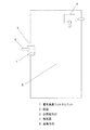
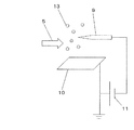
本発明の電気集塵フィルタユニット1を部屋2の自然給気口3に設けた図を図1に示す。部屋の天井裏には部屋2の空気を室外に排出する換気扇4と、また、部屋2の壁には排出した分だけ外の空気を取り入れる自然給気口3が設置されている。電気集塵フィルタユニット1は自然給気口3の中に設けられており、室内に入ってくる空気中の大気塵を除去する機能を有している。そのため通風方向5に沿って自然給気口3から清浄な空気が部屋2の中に入り、部屋2の中は清浄な空気で満たされる。
FIG. 1 shows a diagram in which an electric dust
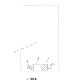
次に、電気集塵フィルタユニット1の下流側に送風機6を設けた図を図2に示す。電気集塵フィルタユニット1の下流側には送風機6が設けられており、送風機6によって部屋2の空気は電気集塵フィルタユニット1に取り込まれる。通風方向5に沿って取り込まれた空気中の大気塵は電気集塵フィルタユニット1によって空気から除去され、大気塵が除去されて清浄になった空気は部屋2の中に戻される。部屋2の空気を取り込み、大気塵を除去して部屋2に戻すことを繰り返すことで部屋2の空気は清浄化される。
Next, the figure which provided the
電気集塵フィルタユニット1の構造を図3に、電気集塵フィルタユニット1を構成するイオン化手段7を図4に、別の形態のイオン化手段7を図5に示す。図3に示すように電気集塵フィルタユニット1は上流側から順にイオン化手段7、フィルタ部8で構成される。空気は通風方向5に沿ってイオン化手段7、フィルタ部8の順に送り込まれる。
The structure of the electrostatic dust
イオン化手段7はX線や紫外線を照射して空気分子を電離することで空気イオンを作るものもあるが、ここでは最も簡単な方法であるコロナ放電を用いたイオン化手段7について説明する。図4に示すイオン化手段7は線状の放電電極9とそれを挟むように設けられたアース電極板10とで構成される。放電電極9には高圧電源11によって高電圧が印加され、アース電極板10にはアースが接続されて0Vとなっており、両者の間でコロナ放電が発生する。イオン化手段7を通過した大気塵12はコロナ放電で発生した空気イオン13と衝突して付着し、帯電する。ここで、イオン化手段7の寸法や印加する高電圧の極性などはコロナ放電が発生する条件であれば一切の限定はないが、一例として、25mmの間隔で設けられた2枚のアース電極板10の中間位置に0.1mm径のタングステンワイヤーからなる放電電極9を設け、アース電極板10をアースに接続し、放電電極9に+6kVの電圧を印加することで正のコロナ放電を発生させることができる。
Some ionization means 7 generate air ions by irradiating X-rays or ultraviolet rays to ionize air molecules. Here, the ionization means 7 using corona discharge, which is the simplest method, will be described. The ionization means 7 shown in FIG. 4 includes a
また、図5に示す別の形態のイオン化手段について以下説明する。図5に示すイオン化手段7は針状の放電電極9の横に一定の間隔を開けてアース電極板10を設けた構造となっている。そして放電電極9に高電圧を印加し、アース電極板10をアースに接続して0Vとすることによってコロナ放電を発生させる。発生したコロナ放電によって空気イオン13が作られ、空気イオン13が大気塵12と結合して大気塵12は帯電する。一例として胴半径1mm、先端半径20〜100μmの先端が鋭利な針状電極を放電電極9として用い、その10mm横にアース電極板10を設け、アース電極板10をアースに接続し、放電電極9に−6kVの電圧を印加することで負のコロナ放電を発生させることができる。
Further, another form of ionization means shown in FIG. 5 will be described below. The ionization means 7 shown in FIG. 5 has a structure in which a
上記説明のように、イオン化手段7によって空気中に空気イオン13が発生し、かつ空気中の大気塵12は帯電する。そして空気イオン13および帯電した大気塵12を含む空気が下流側にあるフィルタ部8に送り込まれる。
As described above, the
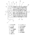
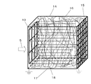
ここで、フィルタ部8の構成を図6に、串状導電体19を図7に、溶融紡糸ノズルを用いた綿状濾過体16の製造方法の一例を図8に示す。図6に示すとおり、綿状濾過体16は一様に混在する帯電繊維17と導電繊維18とを通風方向5に対して綿状に積層することで構成され、フィルタ部8は底部もしくは上部に格子状導電体15を備えたフィルタケース14に綿状濾過体16を収めると同時に導電繊維18と格子状導電体15とを接触導通させた構造となっている。そして格子状導電体15をアースに接続することで導電繊維をアースに接続している。
Here, FIG. 6 shows the configuration of the filter unit 8, FIG. 7 shows the skewer-shaped
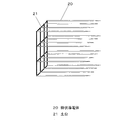
また、図7に示すように串状導電体19は先端を尖らせて綿状濾過体16に突き刺しやすくした複数の棒状導電体20を土台21によって一体化させたものである。土台21は導電性を有するため、棒状導電体20どうしは導通している。図6に示すフィルタ部8は串状導電体19を綿状濾過体16に突き刺して導電繊維18と接触させた後、格子状導電体15と同様に串状導電体19をアースに接続している。こうすることで導電繊維18とアースとの接続を確実にして、確実に高い集塵性能が得られるようにしている。
Further, as shown in FIG. 7, the skewer-shaped
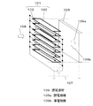
帯電繊維17と導電繊維18とを通風方向5に対して綿状に積層して構成される綿状濾過体16は、図8に示すように2つの溶融紡糸ノズルからそれぞれ帯電繊維17と導電繊維18を吹き出すことで作ることができる。具体的には溶融紡糸ノズルA22から帯電繊維17を、溶融紡糸ノズルB23から導電繊維18を格子状導電体15に向かってフィルタケース14の中に吹き出す。溶融紡糸ノズルA22および溶融紡糸ノズルB23は中央の樹脂押出し孔24から加熱溶融させた樹脂を押し出すと同時に左右に設けた高温圧縮空気孔25から高温圧縮空気を高速で吹き出す。樹脂押出し孔24から押し出された溶融樹脂は左右から高速で吹き出される高温圧縮空気によって細分化され、繊維状になる。このようにして帯電繊維17および導電繊維18は作られる。
A cotton-
使用可能な材料の一例としては、帯電繊維17はポリプロピレン樹脂やポリエステル樹脂を加熱溶融して溶融紡糸ノズルA22から吹き出すことで得られ、その繊維径はおよそ1〜100μmである。導電繊維18は導電性を有するカーボンブラックを一様に含んだポリプロピレン樹脂やポリエステル樹脂を加熱溶融して溶融紡糸ノズルB23から吹き出すことで得られ、その繊維径は帯電繊維と同じくおよそ1〜100μmである。
As an example of a material that can be used, the charged
そして矢印の示す移動方向26の示す方へとフィルタケース14を前後左右に動かすことで、フィルタケース14の中に帯電繊維17と導電繊維18とを水平面に対して一様に混在させることができる。そして混在した帯電繊維17と導電繊維18を図8における上方向、すなわち通風方向に積層することができる。2つの溶融紡糸ノズルからは帯電繊維17および導電繊維18が高速で大量に吹き出されるため、綿状濾過体16は極めて短時間で作成される。そのため大量に生産することが可能である。
Then, by moving the
このようにして構成されたフィルタ部8に空気イオン13および帯電した大気塵12を含む空気が送り込まれる。帯電繊維17は電荷を有する物体が付着することで帯電する性質を有する。そのため図7に示すように次から次へとやってくる空気イオン13が付着して空気イオン13の有する電荷が帯電繊維17に与えられる。帯電繊維17は絶縁性であるため、導電性を有する導電繊維18や格子状導電体15、串状導電体19と接触していても電荷はなくならない。また、たとえ電荷がなくなっても上流側から常時やってくる空気イオン13によって常に帯電した状態を保つ。
Air including
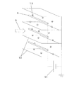
ここで、フィルタ部8を構成する帯電繊維17と導電繊維18とが作る電場を図9に示す。帯電繊維17は常に帯電してその表面に電荷を有した状態であるため、図9に示すようにアースに接続されている導電繊維18には帯電繊維17と逆極性の電荷がアースから誘電されて現れるため、両者の間に矢印で示すような電場が作られる。帯電繊維17と導電繊維18の間には一部が接触しながら微小な隙間が設けられている。隙間が微小であるため両者が作る電場は強い。また、一様に混在した帯電繊維17と導電繊維18とが通風方向5に対して綿状に積層されているため、この強い電場が通風方向5に長く奥行きのある領域全てで作られている。帯電した大気塵12は電場の与えるクーロン力によって帯電繊維17もしくは導電繊維18に付着捕集されるが、このように強くて長い電場を作ることによって集塵性能を大きく高めている。
Here, an electric field generated by the charged
本発明にかかる電気集塵フィルタユニットは、簡単に作成でき、長期間において高い清浄度を有する清浄空気が目詰まりなく得られるため、空気清浄をしながら室外空気を室内に取り入れる換気装置や室内空気を循環的に取り込んできれいにする空気清浄装置の集塵デバイスとして有用である。 The electric dust collecting filter unit according to the present invention can be easily produced and clean air having high cleanness can be obtained without clogging over a long period of time. It is useful as a dust collection device for an air purifier that takes in and cleans the water.
1 電気集塵フィルタユニット
2 部屋
3 自然給気口
4 換気扇
5 通風方向
6 送風機
7 イオン化手段
8 フィルタ部
9 放電電極
10 アース電極板
11 高圧電源
12 大気塵
13 空気イオン
14 フィルタケース
15 格子状導電体
16 綿状濾過体
17 帯電繊維
18 導電繊維
19 串状導電体
20 棒状導電体
21 土台
22 溶融紡糸ノズルA
23 溶融紡糸ノズルB
24 樹脂押出し孔
25 高温圧縮空気孔
26 移動方向
DESCRIPTION OF
23 Melt spinning nozzle B
24
Claims (1)
下流側にフィルタ部とを備えた電気集塵フィルタユニットにおいて、
前記フィルタ部は、一様に混在する帯電繊維と導電繊維とを通風方向に対して綿状に積層して構成される綿状濾過体を、底部もしくは上部に格子状導電体を備えたフィルタケースに収め構成したものであって、
前記綿状濾過体には串状導電体が差し込まれ、
前記導電繊維は、
前記格子状導体または前記串状導電体を通じてアースに接続されている電気集塵フィルタユニット。
Ionization means for ionizing air upstream,
In the electric dust collection filter unit provided with a filter part on the downstream side ,
The filter part is a filter case comprising a cotton-like filter body formed by laminating uniformly charged and conductive fibers mixed in the ventilation direction with a lattice-like conductor at the bottom or top. It is those that were housed configuration,
A skewer-like conductor is inserted into the cotton filter,
The conductive fiber is
An electric dust collection filter unit connected to the ground through the lattice conductor or the skewer conductor.
Priority Applications (1)
| Application Number | Priority Date | Filing Date | Title |
|---|---|---|---|
| JP2013230023A JP6263735B2 (en) | 2013-11-06 | 2013-11-06 | Electric dust filter unit with cotton filter |
Applications Claiming Priority (1)
| Application Number | Priority Date | Filing Date | Title |
|---|---|---|---|
| JP2013230023A JP6263735B2 (en) | 2013-11-06 | 2013-11-06 | Electric dust filter unit with cotton filter |
Publications (2)
| Publication Number | Publication Date |
|---|---|
| JP2015089535A JP2015089535A (en) | 2015-05-11 |
| JP6263735B2 true JP6263735B2 (en) | 2018-01-24 |
Family
ID=53193321
Family Applications (1)
| Application Number | Title | Priority Date | Filing Date |
|---|---|---|---|
| JP2013230023A Active JP6263735B2 (en) | 2013-11-06 | 2013-11-06 | Electric dust filter unit with cotton filter |
Country Status (1)
| Country | Link |
|---|---|
| JP (1) | JP6263735B2 (en) |
Family Cites Families (8)
| Publication number | Priority date | Publication date | Assignee | Title |
|---|---|---|---|---|
| JPH02251256A (en) * | 1989-03-24 | 1990-10-09 | Nippondenso Co Ltd | Air purifier |
| JPH06154651A (en) * | 1992-11-20 | 1994-06-03 | Yasukawa Control Kk | Air cleaner |
| US5817584A (en) * | 1995-12-22 | 1998-10-06 | Kimberly-Clark Worldwide, Inc. | High efficiency breathing mask fabrics |
| JPH1066896A (en) * | 1996-08-28 | 1998-03-10 | Sanyo Electric Co Ltd | Air cleaner |
| JP2795342B2 (en) * | 1997-04-03 | 1998-09-10 | 東洋紡績株式会社 | Mixed web of electret yarn |
| JP2009090165A (en) * | 2007-10-04 | 2009-04-30 | Panasonic Corp | Electrostatic filter device |
| JP2012001865A (en) * | 2010-06-21 | 2012-01-05 | National Institute Of Advanced Industrial & Technology | Fibrous composite material and method for producing the same, and fiber member and functional device which include fibrous composite material |
| JP5489084B2 (en) * | 2011-08-12 | 2014-05-14 | Jnc株式会社 | Mixed fiber non-woven fabric |
-
2013
- 2013-11-06 JP JP2013230023A patent/JP6263735B2/en active Active
Also Published As
| Publication number | Publication date |
|---|---|
| JP2015089535A (en) | 2015-05-11 |
Similar Documents
| Publication | Publication Date | Title |
|---|---|---|
| CA2873601C (en) | Electronic air cleaners and method | |
| KR102535961B1 (en) | Air purifying device, arrangement and method for separating materials from a gas flow | |
| JP6263736B2 (en) | Electric dust filter unit | |
| KR20110088744A (en) | Electrostatic precipitator and its electrode plate | |
| KR101523209B1 (en) | Electric precipitator | |
| CN1980744A (en) | equipment for air purification | |
| CN205146447U (en) | Electrode structure and air purifier | |
| CN210994794U (en) | Electrostatic dust collection components and air purification devices | |
| US2502560A (en) | Electrical gas cleaner unit | |
| CN102500166A (en) | Improved active field polarized media air cleaner | |
| KR102504398B1 (en) | Particle charging apparatus for air conditioners | |
| JPH1190265A (en) | Film electric dust-collecting filter | |
| JP6263735B2 (en) | Electric dust filter unit with cotton filter | |
| JP5556325B2 (en) | Clean air production device and clean air production device with ventilation function | |
| JP7541364B2 (en) | Electrostatic Precipitator | |
| JP2007253055A (en) | Dust collector and air conditioner | |
| JP2011161355A (en) | Dust collecting apparatus | |
| US10245593B2 (en) | Air-filter arrangement | |
| JP2010063964A (en) | Dust collecting apparatus | |
| CN211914193U (en) | Air purification apparatus for separating airborne particles from an air stream | |
| KR102306438B1 (en) | Electric dust collector | |
| JP5223424B2 (en) | Dust collector | |
| JPH08155333A (en) | Air cleaner | |
| JP2012157796A (en) | Dust collecting filter member, dust collecting filter and natural air supply opening using the same, and dust collector | |
| KR102735711B1 (en) | Particle charging apparatus for air conditioners |
Legal Events
| Date | Code | Title | Description |
|---|---|---|---|
| RD01 | Notification of change of attorney |
Free format text: JAPANESE INTERMEDIATE CODE: A7421 Effective date: 20160519 |
|
| A621 | Written request for application examination |
Free format text: JAPANESE INTERMEDIATE CODE: A621 Effective date: 20160930 |
|
| A977 | Report on retrieval |
Free format text: JAPANESE INTERMEDIATE CODE: A971007 Effective date: 20170426 |
|
| A131 | Notification of reasons for refusal |
Free format text: JAPANESE INTERMEDIATE CODE: A131 Effective date: 20170516 |
|
| A521 | Written amendment |
Free format text: JAPANESE INTERMEDIATE CODE: A523 Effective date: 20170518 |
|
| A131 | Notification of reasons for refusal |
Free format text: JAPANESE INTERMEDIATE CODE: A131 Effective date: 20170718 |
|
| A521 | Written amendment |
Free format text: JAPANESE INTERMEDIATE CODE: A523 Effective date: 20170822 |
|
| TRDD | Decision of grant or rejection written | ||
| A01 | Written decision to grant a patent or to grant a registration (utility model) |
Free format text: JAPANESE INTERMEDIATE CODE: A01 Effective date: 20171107 |
|
| A61 | First payment of annual fees (during grant procedure) |
Free format text: JAPANESE INTERMEDIATE CODE: A61 Effective date: 20171120 |
|
| R151 | Written notification of patent or utility model registration |
Ref document number: 6263735 Country of ref document: JP Free format text: JAPANESE INTERMEDIATE CODE: R151 |