JP6263733B2 - Brushless DC motor and blower - Google Patents
Brushless DC motor and blower Download PDFInfo
- Publication number
- JP6263733B2 JP6263733B2 JP2013199552A JP2013199552A JP6263733B2 JP 6263733 B2 JP6263733 B2 JP 6263733B2 JP 2013199552 A JP2013199552 A JP 2013199552A JP 2013199552 A JP2013199552 A JP 2013199552A JP 6263733 B2 JP6263733 B2 JP 6263733B2
- Authority
- JP
- Japan
- Prior art keywords
- connector
- terminal
- brushless
- motor
- stator core
- Prior art date
- Legal status (The legal status is an assumption and is not a legal conclusion. Google has not performed a legal analysis and makes no representation as to the accuracy of the status listed.)
- Active
Links
Images
Landscapes
- Brushless Motors (AREA)
- Motor Or Generator Frames (AREA)
Description
本発明は、天井埋め込み型等の排気用および吸気用の換気装置や、送風機、加湿機、除湿機、冷凍機器、空気調和機、給湯機など、ファン駆動用のブラシレスDCモータおよびそれを搭載した送風装置に関するものである。 The present invention is equipped with a brushless DC motor for driving a fan, such as a ceiling-embedded exhaust and intake ventilator, a blower, a humidifier, a dehumidifier, a refrigeration apparatus, an air conditioner, a water heater, and the like. The present invention relates to a blower.
近年、換気装置等の電気機器に搭載する送風装置においては、装置の消費電力を低減する目的でブラシレスDCモータが使用され場合が増加している。そして、このブラシレスDCモータには、駆動回路基板をモータ内に内蔵するタイプと、駆動回路基板を内蔵せずに外部回路で駆動するタイプに分類される。 In recent years, brushless DC motors are increasingly used in air blowers mounted on electrical devices such as ventilators for the purpose of reducing the power consumption of the devices. The brushless DC motor is classified into a type in which a drive circuit board is built in the motor and a type in which a drive circuit board is not built in and driven by an external circuit.
駆動回路基板をモータ内に内蔵するタイプのモータでは、モータに電源を供給するだけで駆動でき、利便性が高い一方、モータ内の構造が複雑になる。また、装置内に他の制御回路基板がある場合には、モータ内にも駆動回路基板があるので、装置内に2枚の回路基板が存在することになる。 In the motor of the type in which the drive circuit board is built in the motor, it can be driven simply by supplying power to the motor, which is highly convenient, but the structure in the motor is complicated. Further, when there is another control circuit board in the apparatus, there are two circuit boards in the apparatus because there is a driving circuit board in the motor.
駆動回路基板をモータ内に内蔵しないタイプのモータでは、モータ内の構造が簡素化できる一方、駆動する回路を別途設ける必要がある。但し、装置内に他の制御回路基板がある場合には、モータ駆動回路をその制御回路基板に搭載することも可能で、装置内の回路基板を1枚に集約できる利点がある。 In the type of motor in which the drive circuit board is not built in the motor, the structure in the motor can be simplified, but a drive circuit needs to be provided separately. However, when there is another control circuit board in the apparatus, the motor drive circuit can be mounted on the control circuit board, and there is an advantage that the circuit boards in the apparatus can be integrated into one sheet.
従来、この種の駆動回路基板をモータ内に内蔵するブラシレスDCモータは、以下の構成のものが知られている(例えば特許文献1参照)。 2. Description of the Related Art Conventionally, a brushless DC motor having such a drive circuit board built in a motor has the following configuration (see, for example, Patent Document 1).
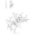
そのブラシレスDCモータについて図7、図8を参照しながら説明する。 The brushless DC motor will be described with reference to FIGS.
図7のステータ構造に示すように、複数枚積層された固定子鉄心101と、この固定子鉄心の表面に絶縁層を形成するインシュレータ102と、固定子鉄心の外周上のインシュレータに端子ピンを立設するための外周孔部106と、固定子鉄心の外周上のインシュレータに駆動回路基板107を保持するための基板保持部108a,108bからステータが構成されている。
As shown in the stator structure of FIG. 7, a plurality of stacked stator cores 101, an
また、図8に示すように、ブラシレスDCモータは、インシュレータ102を介して巻装される巻線と外周孔部106に立設した端子ピン110を接続し、端子ピン110と基板保持部108a,108b保持された駆動回路基板107とを接続し、駆動回路基板107とこの駆動回路基板に保持されたコネクタ103のコネクタ端子109を接続した状態のステータをモールド樹脂105で覆ってモータ外郭を形成し、その中に、回転子104とシャフト111とベアリング112a,112bを一体化したものを入れ、ブラケット113で蓋をした構造である。
Further, as shown in FIG. 8, the brushless DC motor connects the winding wound through the
このような従来の駆動回路基板をモータ内に内蔵するブラシレスDCモータにおいては、駆動回路基板を組込むことによって端子ピン接続やコネクタ保持やコネクタ端子接続が実現できる構成となっていたので、駆動回路基板を内蔵しないブラシレスDCモータを実現しようとした場合でも、配線用基板等の何らかの基板が必要になるという課題を有していた。 In such a conventional brushless DC motor having a built-in drive circuit board in the motor, the drive circuit board has been configured so that terminal pin connection, connector holding, and connector terminal connection can be realized by incorporating the drive circuit board. Even when trying to realize a brushless DC motor without a built-in resistor, there is a problem that some substrate such as a wiring substrate is required.
そこで本発明は、上記従来の課題を解決するものであり、駆動回路基板を内蔵しないブラシレスDCモータにおいて、配線用基板等の基板を必要としないステータ構造を有するブラシレスDCモータを提供することを目的とする。 SUMMARY OF THE INVENTION The present invention solves the above-described conventional problems, and an object of the present invention is to provide a brushless DC motor having a stator structure that does not require a wiring board or the like in a brushless DC motor that does not include a drive circuit board. And
そして、この目的を達成するために、本発明は、複数枚積層された固定子鉄心と、この固定子鉄心の表面に絶縁層を形成するとともに前記固定子鉄心の積層方向の一方の端面と略同一面上で前記固定子鉄心の外周側に突出部を延設するインシュレータと、前記固定子鉄心の外周側で前記突出部に設けたコネクタ保持部と、このコネクタ保持部に装着するコネクタ端子を有するコネクタを備え、前記インシュレータは、前記突出部に複数のコネクタ近傍孔部を有し、前記コネクタ近傍孔部に端子ピンを立設し、前記インシュレータを介して巻装される巻線の端末部を前記端子ピンに接触させてからげるとともに、前記端子ピンを前記コネクタに接続し、端子ピン間隔が前記コネクタ端子の最低間隔の整数倍となることを特徴とするブラシレスDCモータとしたものであり、これにより所期の目的を達成するものである。
In order to achieve this object, the present invention provides a stator core stacked in a plurality of layers, an insulating layer formed on the surface of the stator core, and substantially the same as one end surface of the stator core in the stacking direction. Insulators that extend on the same surface on the outer periphery side of the stator core, a connector holding portion that is provided on the protrusion on the outer periphery side of the stator core, and connector terminals that are attached to the connector holding portion. The insulator has a plurality of connector vicinity holes in the projecting portion, a terminal pin is erected in the connector vicinity hole, and is wound through the insulator. with Karageru in contact with the terminal pins, to connect the terminal pins to the connector, the terminal pin spacing is characterized by comprising an integral multiple of a minimum distance between the connector terminals brushless D Is obtained by a motor, thereby it is to achieve the intended purpose.
本発明によれば、複数枚積層された固定子鉄心と、この固定子鉄心の表面に絶縁層を形成するとともに前記固定子鉄心の積層方向の一方の端面と略同一面上で前記固定子鉄心の外周側に突出部を延設するインシュレータと、前記固定子鉄心の外周側で前記突出部に設けたコネクタ保持部と、このコネクタ保持部に装着するコネクタ端子を有するコネクタを備え、前記インシュレータは、前記突出部に複数のコネクタ近傍孔部を有し、前記コネクタ近傍孔部に端子ピンを立設し、前記インシュレータを介して巻装される巻線の端末部を前記端子ピンに接触させてからげるとともに、前記端子ピンを前記コネクタに接続し、端子ピン間隔が前記コネクタ端子の最低間隔の整数倍となる構成にしたことにより、端子ピンは直接コネクタの端子部に接続されることにより配線用基板を介在することなくモータに電力を供給することができることとなるため、配線用基板等の基板を必要としないステータ構造を有することができ、れにより、部品点数が少なく、簡易な構成のブラシレスDCモータおよびそれを搭載した送風装置を提供することができるという効果を有するものである。
According to the present invention, a plurality of laminated stator cores, and an insulating layer is formed on the surface of the stator core, and the stator core is substantially flush with one end face in the stacking direction of the stator cores. An insulator having a projecting portion extending on the outer peripheral side thereof, a connector holding portion provided on the projecting portion on the outer peripheral side of the stator core, and a connector having a connector terminal attached to the connector holding portion, The projecting portion has a plurality of connector vicinity holes, a terminal pin is erected in the connector vicinity hole, and a terminal portion of a winding wound through the insulator is brought into contact with the terminal pin. with Karageru, the connecting terminal pins to the connector, by the terminal pin interval has a structure comprising an integral multiple of the minimum spacing of the connector terminal, the terminal pins into contact with the terminals of the direct connector As a result, electric power can be supplied to the motor without interposing a wiring board, so that it is possible to have a stator structure that does not require a wiring board or the like, thereby reducing the number of components. The brushless DC motor having a simple configuration and the air blower equipped with the brushless DC motor can be provided.
本発明のブラシレスDCモータは、複数枚積層された固定子鉄心と、この固定子鉄心の表面に絶縁層を形成するとともに前記固定子鉄心の積層方向の一方の端面と略同一面上で前記固定子鉄心の外周側に突出部を延設するインシュレータと、前記固定子鉄心の外周側で前記突出部に設けたコネクタ保持部と、このコネクタ保持部に装着するコネクタ端子を有するコネクタを備え、前記インシュレータは、前記突出部に複数のコネクタ近傍孔部を有し、前記コネクタ近傍孔部に端子ピンを立設し、前記インシュレータを介して巻装される巻線の端末部を前記端子ピンに接触させてからげるとともに、前記端子ピンを前記コネクタに接続し、端子ピン間隔が前記コネクタ端子の最低間隔の整数倍となる構成を有する。
The brushless DC motor of the present invention includes a stator core stacked in a plurality of layers, an insulating layer formed on a surface of the stator core, and the fixed on substantially the same surface as one end surface of the stator core in the stacking direction. An insulator that extends a protruding portion on the outer peripheral side of the core, a connector holding portion provided on the protruding portion on the outer peripheral side of the stator core, and a connector having a connector terminal attached to the connector holding portion, The insulator has a plurality of connector vicinity holes in the protruding portion, a terminal pin is erected in the connector vicinity hole, and a terminal portion of a winding wound through the insulator is in contact with the terminal pin The terminal pins are connected to the connector, and the terminal pin interval is an integral multiple of the minimum interval of the connector terminals .
これにより、端子ピンは直接コネクタの端子部に接続されることにより配線用基板を介在することなくモータに電力を供給することができることとなるため、配線用基板等の基板を必要としないステータ構造を有することができ、これにより、部品点数が少なく、簡易な構成のブラシレスDCモータおよびそれを搭載した送風装置を提供することができるという効果を奏する。 As a result, since the terminal pins are directly connected to the terminal portion of the connector, power can be supplied to the motor without interposing the wiring board, so that the stator structure does not require a board such as a wiring board. Thus, there is an effect that it is possible to provide a brushless DC motor having a simple configuration and a blower equipped with the brushless DC motor with a small number of parts.
また、端子ピン間隔が前記コネクタ端子の最低間隔の整数倍となる構成では、複数のコネクタ端子と複数の端子ピンが同一方向で接触し、複数のコネクタ端子と複数の端子ピンの半田付けによる電気的接続が容易となるという効果を奏する。 Further, in a configuration in which the terminal pin interval is an integral multiple of the minimum interval of the connector terminals , the plurality of connector terminals and the plurality of terminal pins are contacted in the same direction, and the plurality of connector terminals and the plurality of terminal pins are electrically soldered. The effect is that easy connection is facilitated.
また、複数の前記コネクタ端子の少なくとも一つは略L字状に折り曲げられた形状でも良い。 Further, at least one of the plurality of connector terminals may be bent in a substantially L shape.
また、前記端子ピンは複数の前記コネクタ端子のL字先端部に略平行で隣接するように配置され、前記コネクタ端子部のL字先端部と前記端子ピンが接触する構成にしても良い。これにより、前記コネクタ端子と前記端子ピンの接触面積が増大し、はんだ付け作業が容易となるとともに、半田付けによる電気的接続面積が増大し、半田接続部分の機械的強度が増すとともに、電気的接続の信頼性が増すこととなるという効果を奏する。 The terminal pins may be arranged so as to be substantially parallel to and adjacent to the L-shaped tip portions of the plurality of connector terminals, and the L-shaped tip portions of the connector terminal portions may be in contact with the terminal pins. This increases the contact area between the connector terminal and the terminal pin, facilitates the soldering operation, increases the electrical connection area by soldering, increases the mechanical strength of the solder connection portion, There is an effect that the reliability of the connection is increased.
また、前記コネクタ端子部のL字先端部と前記端子ピンを接触させ、補強部材を被せた構成としても良い。 Moreover, it is good also as a structure which contacted the L-shaped front-end | tip part of the said connector terminal part, and the said terminal pin, and covered the reinforcement member.
また、前記補強部材はスリーブでも良い。これにより、前記補強部材のスリーブを被せた後、半田付けにより、前記コネクタ端子のL字先端部と前記端子ピンとを電気的かつ機械的に接続保持し、半田接続部分の機械的強度が増すとともに、電気的接続の信頼性が増すこととなるという効果を奏する。 The reinforcing member may be a sleeve. Thereby, after covering the sleeve of the reinforcing member, the L-shaped tip portion of the connector terminal and the terminal pin are electrically and mechanically connected and held by soldering, and the mechanical strength of the solder connection portion is increased. There is an effect that the reliability of the electrical connection is increased.
また、複数の前記コネクタ端子部は巻線と接続されている端子ピンと接続されるコネクタ端子部のみ略L字状に折り曲げられた形状であり、その他のコネクタ端子部はストレートであっても良い。これにより、前記コネクタ端子のL字先端部と前記端子ピンの半田接続部分と隣り合う前記コネクタ端子のL字先端部がなくなるため、はんだ付け作業が容易となるという効果を奏する。 In addition, the plurality of connector terminal portions may have a shape in which only the connector terminal portion connected to the terminal pin connected to the winding is bent in a substantially L shape, and the other connector terminal portions may be straight. As a result, the L-shaped tip portion of the connector terminal and the L-shaped tip portion of the connector terminal adjacent to the solder connection portion of the terminal pin are eliminated, so that the soldering operation is facilitated.
以下、本発明の実施の形態について図面を参照しながら説明する。 Hereinafter, embodiments of the present invention will be described with reference to the drawings.
(実施の形態1)
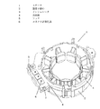
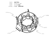
図1に示すように、本実施形態のステータ1は、複数枚積層された固定子鉄心2と、固定子鉄心2の表面に絶縁層を形成するとともに前記固定子鉄心の積層方向の一方の端面と略同一面上で固定子鉄心2の外周側に突出部4を延設するインシュレータ3と、突出部4に設けたコネクタ保持部としてのフック5と、フック5間のインシュレータ3に端子ピン12を3本立設するためのコネクタ近傍孔部6から成る。
(Embodiment 1)
As shown in FIG. 1, the
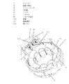
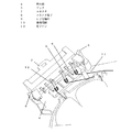
図2に示すように、コネクタ近傍孔部6に端子ピン12を3本立設し、この端子ピン12の低部(インシュレータ3の突出部4側)に3相の巻線端部11をからげてはんだ接続する。更に、フック5にコネクタ7を取り付ける。コネクタ端子8はコネクタ7に圧入されて固定保持されているが、図2、3に示すように、本実施形態では6個中4個をその巻線10側の形状を突出部4の反対側に略L字状に折り曲げられた形状としている。
As shown in FIG. 2, three terminal pins 12 are erected in the connector
ここで、端子ピン12はコネクタ端子8のL字先端部9と略平行で隣接するように配置されている。この状態でコネクタ端子8と端子ピン12の上部をはんだ接続する。図4に示すように、ステータ1は外郭を構成する樹脂13にて一体的に成形固化され、磁石を有するロータ14とブラケット15にて組み立てられブラシレスDCモータ16となる。
Here, the terminal pins 12 are arranged so as to be substantially parallel to and adjacent to the L-
以上のような構成の駆動回路を内蔵しない本実施の形態のブラシレスDCモータ16は、外付けの駆動回路(図示せず)とコネクタ7とで接続され、コネクタ端子8から巻線10へと駆動回路からの電源等を供給し回転制御するセンサレスのブラシレスDCモータとなる。
The
本実施の形態のおける特徴は、端子ピン12とコネクタ端子8の接続方法である。すなわち、端子ピン12をコネクタ端子8の上側に折り曲げたL字先端部9に接触させ、直接半田付けにて接続している。
A feature of the present embodiment is a connection method between the terminal pins 12 and the
これにより、配線用基板等の基板を必要としないステータ構造を有するブラシレスDCモータ16を提供できるものである。
Accordingly, the
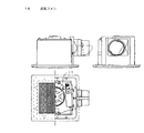
また、図6は送風ファン18を本実施の形態1のブラシレスDCモータに取り付けた送風装置である。つまり、配線用基板等の基板を必要としないステータ構造を有するブラシレスDCモータ16がコスト低減することにより、ブラシレスDCモータを搭載した送風装置のコストも低減させることができるものである。
FIG. 6 shows a blower device in which the blower fan 18 is attached to the brushless DC motor of the first embodiment. In other words, the cost of the
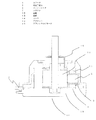
なお、図5に示すような前記コネクタ端子8のL字先端部9と前記端子ピン12を接触させ、補強部材を被せた構成としても良い。補強部材である小型の金属性のスリーブ17を被せた後、ハンダ付け(図示せず)などにより、コネクタ端子8のL字先端部9と端子ピン12とを電気的かつ機械的に接続保持する。
In addition, it is good also as a structure which made the L-shaped front-end | tip
つまり、補強部材であるスリーブ17を被せたことにより、半田接続部分の機械的強度が増すとともに、電気的接続の信頼性が増すこととなる。
That is, by covering the
なお、コネクタ端子8は、本実施形態では6個中4個をその巻線10側の形状を突出部4の反対側に略L字状に折り曲げられた形状としているが、略L字状に折り曲げられていなくてもよい。その場合、コネクタ端子8と端子ピン12の接触面積は略L字状に折り曲げられた形状に対し小さくなるため、半田付けによる電気的接続面積が縮小し、半田接続部分の機械的強度が減少するとともに、電気的接続の信頼性が低下するため、略L字状に折り曲げられていることが望ましい。
In the present embodiment, four of the six
なお、コネクタ端子8のピッチと端子ピン12の最低間隔の整数倍にならなくても良い。その場合、端子ピン12とコネクタ端子8の隣接する方向が一部逆となるため、コネクタ組み付け作業にて隣接する方向が入れ替わる組み付け不良が発生しても気づきにくくなってしまう。また、半田接続箇所の間隔が狭くなる場合もあるため、半田接続作業に不良が発生しやすくなる。よって、コネクタ端子8のピッチと端子ピン12の最低間隔の整数倍になることが望ましい。
It should be noted that the pitch of the
以上のように本発明にかかるブラシレスDCモータは、複数枚積層された固定子鉄心と、この固定子鉄心の表面に絶縁層を形成するとともに前記固定子鉄心の積層方向の一方の端面と略同一面上で前記固定子鉄心の外周側に突出部を延設するインシュレータと、前記固定子鉄心の外周側で前記突出部に設けたコネクタ保持部と、このコネクタ保持部に装着するコネクタ端子を有するコネクタを備え、前記インシュレータは、前記突出部に複数のコネクタ近傍孔部を有し、前記コネクタ近傍孔部に端子ピンを立設し、前記インシュレータを介して巻装される巻線の端末部を前記端子ピンに接触させてからげるとともに、前記端子ピンを前記コネクタに接続したという構成を有することにより配線用基板を介在することなくモータに電力を供給することができることとなり、コスト低減させることができるものである。 As described above, the brushless DC motor according to the present invention includes a stator core stacked in a plurality of layers, an insulating layer formed on the surface of the stator core, and substantially the same as one end surface in the stacking direction of the stator core. An insulator extending on the outer peripheral side of the stator core on the surface; a connector holding portion provided on the protruding portion on the outer peripheral side of the stator core; and a connector terminal to be attached to the connector holding portion. The insulator includes a plurality of connector vicinity holes in the projecting portion, a terminal pin is erected in the connector vicinity hole, and a terminal portion of a winding wound through the insulator is provided. Power is supplied to the motor without interposing a wiring board by having the configuration in which the terminal pin is connected to the connector while being brought into contact with the terminal pin. It will be able to be one in which it is possible to reduce costs.
従って、低コスト化が要求されるブラシレスDCモータや家電用や業務用などの送風装置として活用できる。 Therefore, it can be utilized as a brushless DC motor that is required to reduce the cost, or as a blower for home appliances or business use.
1 ステータ
2 固定子鉄心
3 インシュレータ
4 突出部
5 フック
6 コネクタ近傍孔部
7 コネクタ
8 コネクタ端子
9 L字先端部
10 巻線
11 巻線端部
12 端子ピン
13 樹脂
14 ロータ
15 ブラケット
16 ブラシレスDCモータ
17 スリーブ
18 送風ファン
DESCRIPTION OF
Claims (8)
前記インシュレータは、前記突出部に複数のコネクタ近傍孔部を有し、前記コネクタ近傍孔部に端子ピンを立設し、前記インシュレータを介して巻装される巻線の端末部を前記端子ピンに接触させてからげるとともに、前記端子ピンを前記コネクタに接続し、
端子ピン間隔が前記コネクタ端子の最低間隔の整数倍となることを特徴とするブラシレスDCモータ。 A plurality of laminated stator cores, and an insulating layer formed on the surface of the stator core, and a protruding portion on the outer peripheral side of the stator core on the same plane as one end face in the stacking direction of the stator core An insulator that extends, a connector holding portion provided in the protruding portion on the outer peripheral side of the stator core, and a connector having a connector terminal attached to the connector holding portion,
The insulator has a plurality of connector vicinity holes in the projecting portion, a terminal pin is erected in the connector vicinity hole, and a terminal portion of a winding wound through the insulator is used as the terminal pin. The contact pin is lifted and the terminal pin is connected to the connector ,
A brushless DC motor characterized in that the terminal pin interval is an integral multiple of the minimum interval of the connector terminals .
前記インシュレータは、前記突出部に複数のコネクタ近傍孔部を有し、前記コネクタ近傍孔部に端子ピンを立設し、前記インシュレータを介して巻装される巻線の端末部を前記端子ピンに接触させてからげるとともに、前記端子ピンを前記コネクタに接続し、
複数の前記コネクタ端子の少なくとも一つは略L字状に折り曲げられた形状であることを特徴とするブラシレスDCモータ。 A plurality of laminated stator cores, and an insulating layer formed on the surface of the stator core, and a protruding portion on the outer peripheral side of the stator core on the same plane as one end face in the stacking direction of the stator core An insulator that extends, a connector holding portion provided in the protruding portion on the outer peripheral side of the stator core, and a connector having a connector terminal attached to the connector holding portion,
The insulator has a plurality of connector vicinity holes in the projecting portion, a terminal pin is erected in the connector vicinity hole, and a terminal portion of a winding wound through the insulator is used as the terminal pin. The contact pin is lifted and the terminal pin is connected to the connector,
A brushless DC motor, wherein at least one of the plurality of connector terminals has a shape bent into a substantially L shape.
It has a blower fan, a motor for driving the blower fan blower, which is a brushless DC motor according to any one of claims 1 to 7.
Priority Applications (5)
| Application Number | Priority Date | Filing Date | Title |
|---|---|---|---|
| JP2013199552A JP6263733B2 (en) | 2013-09-26 | 2013-09-26 | Brushless DC motor and blower |
| US14/916,331 US10158268B2 (en) | 2013-09-17 | 2014-09-16 | Brushless DC motor and ventilation device having same mounted therein |
| CN201480051310.4A CN105556804B (en) | 2013-09-17 | 2014-09-16 | Brushless DC motor and blower device equipped with the same |
| CN201810396916.1A CN108539894B (en) | 2013-09-17 | 2014-09-16 | Brushless DC motor and blower device equipped with same |
| PCT/JP2014/004748 WO2015040852A1 (en) | 2013-09-17 | 2014-09-16 | Brushless dc motor and ventilation device having same mounted therein |
Applications Claiming Priority (1)
| Application Number | Priority Date | Filing Date | Title |
|---|---|---|---|
| JP2013199552A JP6263733B2 (en) | 2013-09-26 | 2013-09-26 | Brushless DC motor and blower |
Publications (2)
| Publication Number | Publication Date |
|---|---|
| JP2015065790A JP2015065790A (en) | 2015-04-09 |
| JP6263733B2 true JP6263733B2 (en) | 2018-01-24 |
Family
ID=52833216
Family Applications (1)
| Application Number | Title | Priority Date | Filing Date |
|---|---|---|---|
| JP2013199552A Active JP6263733B2 (en) | 2013-09-17 | 2013-09-26 | Brushless DC motor and blower |
Country Status (1)
| Country | Link |
|---|---|
| JP (1) | JP6263733B2 (en) |
Families Citing this family (2)
| Publication number | Priority date | Publication date | Assignee | Title |
|---|---|---|---|---|
| US10897174B2 (en) | 2016-06-28 | 2021-01-19 | Mitsubishi Electric Corporation | Stator, motor, and air conditioner |
| KR102201386B1 (en) | 2019-02-20 | 2021-01-12 | 엘지전자 주식회사 | Fan motor |
Family Cites Families (4)
| Publication number | Priority date | Publication date | Assignee | Title |
|---|---|---|---|---|
| JPH0574158U (en) * | 1992-03-12 | 1993-10-08 | 株式会社芝浦製作所 | Small electric motor with spool with terminals |
| JPH06351184A (en) * | 1993-06-10 | 1994-12-22 | Matsushita Electric Ind Co Ltd | Motor |
| JPH10201160A (en) * | 1997-01-16 | 1998-07-31 | Matsushita Seiko Co Ltd | Brushless motor stator |
| JP3916990B2 (en) * | 2001-03-30 | 2007-05-23 | 山洋電気株式会社 | Lead wire connection structure |
-
2013
- 2013-09-26 JP JP2013199552A patent/JP6263733B2/en active Active
Also Published As
| Publication number | Publication date |
|---|---|
| JP2015065790A (en) | 2015-04-09 |
Similar Documents
| Publication | Publication Date | Title |
|---|---|---|
| US10158268B2 (en) | Brushless DC motor and ventilation device having same mounted therein | |
| KR101221259B1 (en) | motor | |
| JP5993087B2 (en) | Motor and manufacturing method thereof | |
| CN208015465U (en) | Motor and electrical equipment | |
| TWI638504B (en) | Fan motor, inline type fan motor and assembly method of the same | |
| JP5200521B2 (en) | Motor and cooling fan | |
| CN101682224A (en) | Stator for aspiration motor, aspiration motor and in-car sensor using the same | |
| CN203896077U (en) | Molded stators, molded electric motors and air conditioners | |
| CN104079099B (en) | Motor | |
| KR102132250B1 (en) | Stator, electric motor, and air conditioner | |
| WO2016063396A1 (en) | Wiring board, electric motor, electric apparatus, and air conditioner | |
| JP6263733B2 (en) | Brushless DC motor and blower | |
| JP2012253845A (en) | Motor and ventilating fan | |
| JP6263732B2 (en) | Brushless DC motor and blower | |
| JP6175648B2 (en) | Brushless DC motor and blower | |
| JP2011109861A (en) | Molded motor | |
| CN203800712U (en) | Molded stators, molded electric motors and air conditioners | |
| JP2012200114A (en) | Mold electric motor and blower equipped with the same | |
| JP2012253847A (en) | Motor | |
| CN223816042U (en) | Stator structure for electric motors and electric motors | |
| JP2013223394A (en) | Stator of synchronous rotation machine and air-conditioning brushless dc fan motor | |
| WO2018163414A1 (en) | Dynamo-electric machine and method for manufacturing dynamo-electric machine | |
| JP6452823B2 (en) | Electric motor and air conditioner |
Legal Events
| Date | Code | Title | Description |
|---|---|---|---|
| RD01 | Notification of change of attorney |
Free format text: JAPANESE INTERMEDIATE CODE: A7421 Effective date: 20160519 |
|
| A621 | Written request for application examination |
Free format text: JAPANESE INTERMEDIATE CODE: A621 Effective date: 20160719 |
|
| A131 | Notification of reasons for refusal |
Free format text: JAPANESE INTERMEDIATE CODE: A131 Effective date: 20170530 |
|
| A521 | Written amendment |
Free format text: JAPANESE INTERMEDIATE CODE: A523 Effective date: 20170718 |
|
| TRDD | Decision of grant or rejection written | ||
| A01 | Written decision to grant a patent or to grant a registration (utility model) |
Free format text: JAPANESE INTERMEDIATE CODE: A01 Effective date: 20171107 |
|
| A61 | First payment of annual fees (during grant procedure) |
Free format text: JAPANESE INTERMEDIATE CODE: A61 Effective date: 20171120 |
|
| R151 | Written notification of patent or utility model registration |
Ref document number: 6263733 Country of ref document: JP Free format text: JAPANESE INTERMEDIATE CODE: R151 |