JP6261545B2 - Image forming apparatus - Google Patents
Image forming apparatus Download PDFInfo
- Publication number
- JP6261545B2 JP6261545B2 JP2015144069A JP2015144069A JP6261545B2 JP 6261545 B2 JP6261545 B2 JP 6261545B2 JP 2015144069 A JP2015144069 A JP 2015144069A JP 2015144069 A JP2015144069 A JP 2015144069A JP 6261545 B2 JP6261545 B2 JP 6261545B2
- Authority
- JP
- Japan
- Prior art keywords
- temperature
- image
- forming apparatus
- image forming
- fixing
- Prior art date
- Legal status (The legal status is an assumption and is not a legal conclusion. Google has not performed a legal analysis and makes no representation as to the accuracy of the status listed.)
- Active
Links
Images


Description
本発明は、電子写真方式を採用した複写機やプリンター、あるいはファクシミリ等の画像形成装置において、現像剤像をシート上に定着させる定着機や画像を形成したシートの冷却方法に関する。 The present invention relates to a fixing machine for fixing a developer image on a sheet and a cooling method for a sheet on which an image is formed in an image forming apparatus such as a copying machine, a printer, or a facsimile employing an electrophotographic system.
従来、電子写真方式を用いる画像形成装置においては、トナーなどの現像剤で表面に現像剤像を形成したシートを、定着機の加熱用ローラと加圧用ローラからなる定着ローラ対で挟持搬送し、加熱および加圧して定着を行う。 Conventionally, in an image forming apparatus using an electrophotographic system, a sheet having a developer image formed on a surface with a developer such as toner is nipped and conveyed by a pair of fixing rollers composed of a heating roller and a pressure roller of a fixing machine, Fix by heating and pressing.
このような画像形成装置において、定着機の定着ローラ対の最大幅よりも狭いシートを挟持搬送すると、定着ローラ対のシートが通過しない部分ではシートに熱が吸収されないため、シートが通過する部分よりも温度が上昇し、温度分布が不均一となる。
そこで、定着ローラ対の温度分布を均一化するために、シートの幅に応じて定着ローラ対を冷却するファンを制御するものが開示されている。(特許文献1参照)
また、画像を形成したシートが熱を持ったまま排出されて重なると、軟化した現像剤により、重なったシート同士が付着してしまう場合がある。付着したシート同士を剥離させると、シート上に形成した画像やシートが破損することがある。
そこで、定着機で加熱および加圧された後のシートへ、ファンから空気を吹き付けて冷却するものが開示されている。(特許文献2参照)
In order to make the temperature distribution of the fixing roller pair uniform, a fan that controls a fan that cools the fixing roller pair according to the width of the sheet is disclosed. (See Patent Document 1)
In addition, when sheets on which images are formed are discharged and overlapped with heat, the overlapped sheets may adhere to each other due to the softened developer. When the attached sheets are separated from each other, an image or a sheet formed on the sheet may be damaged.
In view of this, a sheet is disclosed in which air is blown from a fan onto a sheet that has been heated and pressurized by a fixing machine and then cooled. (See Patent Document 2)
しかしながら、定着時のシートへの加熱によりシートに含まれる水分が蒸発すると、周囲の空気が加湿される。この加湿された空気が、ファンによる気流で画像形成装置内部の露光装置としてのレーザスキャナ周辺に移動すると、画像形成装置の周囲の環境によっては、レーザスキャナ上で結露してしまうという課題がある。
レーザスキャナの、特にレーザ射出部で結露が発生すると、像担持体としての感光体ドラム上に静電潜像を形成するために必要な光量を、レーザスキャナが出力できず、画像形成時に不具合を引き起こしてしまう場合がある。
However, when moisture contained in the sheet evaporates due to heating of the sheet during fixing, the surrounding air is humidified. When the humidified air moves to the periphery of the laser scanner as the exposure device inside the image forming apparatus by the airflow generated by the fan, there is a problem that condensation occurs on the laser scanner depending on the environment around the image forming apparatus.
If dew condensation occurs in the laser scanner, especially at the laser emission part, the laser scanner cannot output the amount of light necessary to form an electrostatic latent image on the photosensitive drum as the image carrier, causing problems during image formation. It may cause.
本発明は、定着機や画像形成後のシートを冷却する際において、露光装置における結露の発生を防止し、安定して画像を形成することを目的とする。 An object of the present invention is to prevent the formation of condensation in an exposure apparatus and coolly form an image when a fixing machine or a sheet after image formation is cooled.
前記目的を達成するために、本発明は、
画像形成装置であって、
画像データに応じて像担持体を露光し、静電潜像を形成する露光手段と、
前記露光手段により静電潜像が形成された像担持体をトナー像に現像する現像手段と、
前記現像手段により現像されたトナー像を記録媒体に転写する転写手段と、
前記転写手段により記録媒体に転写されたトナー像を熱により記録媒体に定着させる定着手段と、
前記定着手段の周辺の空気が前記露光手段に向かう気流を発生させる送風手段と、
前記画像形成装置内部の温度を検出する温度検出手段と、
前記温度検出手段が所定温度未満の第1の温度範囲の温度を検出した時に前記定着手段を第1の設定温度とし、前記温度検出手段が前記所定温度以上の第2の温度範囲の温度を検出した時に前記定着手段を前記第1の設定温度よりも低い第2の設定温度とする温度設定手段と、
前記温度検出手段が前記第1の温度範囲の温度を検出したときに前記送風手段による送風を停止し、前記温度検出手段が前記第2の温度範囲の温度を検出したときに前記送風手段による送風を行う制御手段と、
により画像形成装置を構成している。
In order to achieve the above object, the present invention provides:
An image forming apparatus,
Exposure means for exposing the image carrier in accordance with image data to form an electrostatic latent image;
Developing means for developing an image carrier having an electrostatic latent image formed thereon by the exposure means into a toner image;
Transfer means for transferring the toner image developed by the developing means to a recording medium;
Fixing means for fixing the toner image transferred to the recording medium by the transfer means to the recording medium by heat;
An air blower for generating an airflow toward the exposure unit by air around the fixing unit;
Temperature detecting means for detecting the temperature inside the image forming apparatus;
When the temperature detection means detects a temperature in a first temperature range less than a predetermined temperature, the fixing means is set to a first set temperature, and the temperature detection means detects a temperature in a second temperature range equal to or higher than the predetermined temperature. A temperature setting means for setting the fixing means to a second set temperature lower than the first set temperature,
When the temperature detecting means detects the temperature in the first temperature range, the blowing by the blowing means is stopped, and when the temperature detecting means detects the temperature in the second temperature range, the blowing by the blowing means Control means for performing
Thus, an image forming apparatus is configured.
本発明の画像形成装置によれば、定着機や画像形成後のシートを冷却する際において、露光装置における結露の発生を防止し、安定して画像を形成することが可能となる。 According to the image forming apparatus of the present invention, when the fixing machine and the sheet after image formation are cooled, it is possible to prevent the occurrence of condensation in the exposure apparatus and form an image stably.
以下、本発明の実施の形態を図に基づいて説明する。 Hereinafter, embodiments of the present invention will be described with reference to the drawings.
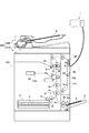
図1は本発明の実施形態における画像形成装置の概略断面図であり、画像読取装置200と画像形成装置100とからなる。
FIG. 1 is a schematic cross-sectional view of an image forming apparatus according to an embodiment of the present invention, and includes an
図1において、画像読取装置200は、原稿の画像を読み取る画像読取部210と、原稿Dを画像読取部210へ給送する原稿給送部220から構成されている。
画像形成装置100には、下部から上部に向かって順に、シート給送部10、画像形成部20、定着部30、シート排出部40が設けられている。また、画像形成部20、定着部30の右側には、シート再給送部50が設けられている。
In FIG. 1, the
The
シート給送部10では、給送カセット11や手差しトレイ17に積載されたシートSを画像形成部20へ給送する。給送カセット11に収納されたシートSは、ピックアップローラ12が回転することによって分離ローラ対13へ給送される。シートSが重送している場合は、正転ローラと反転ローラとからなる分離ローラ対13によって1枚に分離され、実線で示す給送パスPS1に供給される。
In the
次に、シートSは、給送ローラ対15によってレジストローラ対16に搬送される。ここで、回転を停止しているレジストローラ対16のニップにシートSの先端を倣わせることで、シートSの斜行を矯正する。なお、マルチ給紙トレイ17からシートSを給送する場合は、供給ローラ18aおよび分離パッド18bによってシートを1枚に分離する。そして、供給ローラ対19によって給送ローラ対15に供給され、レジストローラ対16に搬送されることでシートSの斜行が矯正される。
斜行が矯正されたシートは、所定のタイミングで回転するレジストローラ対16によって画像形成部20に搬送される。
Next, the sheet S is conveyed to the
The sheet whose skew has been corrected is conveyed to the
画像形成部20では、帯電ローラ22によって感光ドラム21がその表面を均一に帯電されている。レーザユニット23から画像情報に対応したレーザ光が照射されると、感光ドラム21のレーザ光が照射された部分は、帯電ローラ22によって帯電されていた電荷が除去され、画像情報に対応した静電潜像が形成される。ここで形成された静電潜像は、現像装置の現像ローラ24によって現像剤が付着され、現像剤像として可視化される。
In the
この現像剤像は、感光ドラム21の回転によって転写ニップ部N1に搬送される。このタイミングに合わせてレジストローラ対16からシートSが転写ニップ部N1に搬送される。搬送されたシートSは、転写ニップ部N1において感光ドラム21と転写ローラ25に挟持搬送される。このとき転写ローラ25からのバイアス電圧印加によって感光ドラム21に形成された現像剤像がシートSに転写される。なお、レーザユニット23から照射されるレーザ光は、画像読取装置200あるいはホストPC1より送信された画像データに基づいて制御される。
The developer image is conveyed to the transfer nip portion N1 by the rotation of the
次に、現像剤像が形成されたシートSは、定着部30へと搬送される。定着部30は、不図示のハロゲンランプ等の熱源、定着ローラ31、加圧ローラ32から構成される。定着ローラ31はアルミ等の材質からなり、熱源により所定の温度に加熱される。加圧ローラ32は定着ローラ31に接触して所定の圧力で加圧するよう設置され、定着ニップ部N2を形成する。
Next, the sheet S on which the developer image is formed is conveyed to the
現像剤像が形成されたシートSは、定着ニップ部N2に送り込まれて、定着ローラ31と加圧ローラ32とで挟持搬送される。このときに加熱加圧されることで、現像剤像がシートS上に定着される。なお、定着部30は、定着ローラ31で加熱する加熱ローラ方式の他に、図3の加圧ローラ32が端部レスフィルムを介してセラミックヒータ33等の熱源を加圧することで定着ニップ部N2を形成し、ニップ部N2にてシートSを挟持搬送しながら加熱加圧するオンデマンド定着方式を用いても良い。
The sheet S on which the developer image is formed is sent to the fixing nip portion N2 and is nipped and conveyed by the
次に、現像剤像が定着されたシートSは、シート排出部40へと搬送され、排出ローラ対41によって排出トレイ42へ排出される。
シートSの両面に画像を形成する場合は、1面目に画像形成されたシートSが排出ローラ対41によって搬送されているときに、シートSの後端が排出ローラ対41を抜ける前に排出ローラ対41を一旦停止させ、さらに排出ローラ対41を逆回転させることで、シートSを反転させてシート再給送部50へ搬送する。
シート再給送部50へ搬送されたシートSは、再給送ローラ対51a、51bによって破線で示す再給送パスPS2を搬送され、再給送ローラ対51cによってレジストローラ対16に搬送される。そして、レジストローラ対16によって斜行を矯正された後、裏面が転写ニップ部N1に搬送されることで、シートSの2面目に現像剤像が形成される。その後は、表面に画像形成したときと同様に定着ニップ部N2を搬送されることで現像剤像がシートSに定着され、両面に画像が形成されたシートSは排出ローラ対41によって排出トレイ42へ排出される。
Next, the sheet S on which the developer image is fixed is conveyed to the
When images are formed on both sides of the sheet S, the discharge roller before the trailing edge of the sheet S passes through the
The sheet S conveyed to the
また、画像形成装置100の内部には、環境センサS1が設置されており、画像形成装置内の温度、湿度を電気信号として検出可能である。温度の検出手段としてはサーミスタが、湿度の検出手段としては静電容量センサが一般的に知られており、本実施例においてはそれらを組み合わせた複合センサを備える。
In addition, an environmental sensor S1 is installed inside the
図2は図1の画像形成システムの制御ブロック図である。図2において、101は制御手段としてのCPUである。このCPU101は入力データの記憶や作業用記憶領域等として用いるRAM102と、制御手順等のプログラムを記憶したROM103を備える。CPU101は外部インターフェース2を介してホストPC1と接続され、画像データの受信や装置ステータスの送信などを行う。
CPU101は、読取走査ユニット250による原稿の読取動作及び原稿の搬送動作を制御する画像読取装置制御部120、画像読取装置制御部120もしくはホストPC1からの画像信号を処理する画像信号処理部110、画像信号処理部110から送られる画像信号に応じてシートに画像を形成する画像形成装置制御部130、本体の設定等を行うほかユーザーへのメッセージ等を表示する操作・表示部140と接続される。
FIG. 2 is a control block diagram of the image forming system of FIG. In FIG. 2, 101 is a CPU as a control means. The
The
図3は図2における画像形成装置制御部130のブロック図である。図3において、画像形成装置制御部120は、図2の画像形成システムの制御ブロック図と同じく、入力データの記憶や作業用記憶領域等として用いるRAM122と制御手順等のプログラムを記憶したROM123とを備えた、制御手段としてのCPU121を備える。
CPU121には、I/Oポート124を介して、帯電ローラ22、現像ローラ24、転写ローラ24、熱源としてのセラミックヒータ33に電圧を印加するための電圧制御ユニットU1と、図1の感光ドラム21表面を露光するためのレーザユニット23と、共通駆動モータドライバD1と、ファンモータドライバD2と、が接続されている。
共通駆動モータドライバD1は、感光ドラム21、現像ローラ24、転写ローラ25を回転させる駆動源としての共通駆動モータM1の動作を制御する。ファンモータドライバD2は、図1において定着部30とシートSを冷却する冷却ファン60を駆動するファンモータM2の動作を制御する。
また、CPU121には環境センサS1が接続されており、画像形成装置内の温度、湿度を検出可能である。画像形成装置内の温度、湿度は、装置内部の環境を直接検出するほかに、装置外部の環境の検出結果から判定してもよい。
FIG. 3 is a block diagram of the image forming
The
The common drive motor driver D1 controls the operation of the common drive motor M1 as a drive source for rotating the
An environmental sensor S1 is connected to the
図4は従来の画像形成装置において、機内の空気の流れを説明する図である。図4において、矢印Aは空気の流れを示す。
定着部30において加熱・加圧された後のシートSと、定着部30とを冷却するために、冷却ファン60は、機外の空気を常に一定の風量で、定着部30とシートSとに吹き付けている。シートSが定着部30で加熱されると、シートSに含まれる水分は水蒸気となって放出され、定着部30周辺の空気の温湿度が上昇する。
FIG. 4 is a view for explaining the air flow in the apparatus in the conventional image forming apparatus. In FIG. 4, an arrow A indicates the flow of air.
In order to cool the sheet S that has been heated and pressurized in the fixing
湿度の高い空気が、冷却ファン60による気流により、露光装置としてのレーザスキャナ23へ到達すると、レーザスキャナ23に結露が発生する場合がある。特に、レーザスキャナ23のレーザ出力部に設けられた、透明な部材で構成される防塵部材23aの表面で結露が生じると、出力画像の濃度低下などの画像不良が発生する場合がある。これは、防塵部材23aの表面に結露が生じると、レーザスキャナ23から感光体ドラム21へ照射されるレーザの光量が低下するためである。
When high-humidity air reaches the
図5は本実施例による画像形成装置における、機内の空気の流れを説明する図である。矢印Bは空気の流れを示す。
冷却ファン60の風量は、図3のCPU121によって、図3のファンモータドライバD1を介してファンモータM2が制御されることにより、調整される。冷却ファン60の風量は、発生した気流が画像形成装置100の各部品に遮断されてレーザスキャナ23に到達しない程度に調整される。本実施例においては全速(100%)駆動に対して半速(50%)の出力に調整している。
FIG. 5 is a view for explaining the air flow in the apparatus in the image forming apparatus according to the present embodiment. Arrow B indicates the flow of air.
The air volume of the cooling
図6は図5の環境センサS1の出力結果に対する、図5の冷却ファン60の駆動制御を表すテーブルである。温度と湿度による結露の発生しやすさにより、環境条件を、領域A、領域B、領域Cの3つの領域に分割している。図3のCPU121は、図3および図5の環境センサS1の出力と図6のテーブルを照合し、環境条件が領域A、領域B、領域Cのどの領域に含まれるかによって、図5の冷却ファン60の制御を変更する。
環境条件として、温度が低いほど、また湿度が高いほど、装置内での結露が発生しやすくなる。そのため、低温領域もしくは高湿領域において冷却ファン60の風量を低減するよう、テーブルの内容を設定する。
6 is a table showing drive control of the cooling
As the environmental conditions, the lower the temperature and the higher the humidity, the more likely condensation occurs in the apparatus. Therefore, the contents of the table are set so as to reduce the air volume of the cooling
図7のフローチャートに基づいて、本実施例における冷却方法について説明を行う。図7の処理は、図3のROM123内に格納されているプログラムを、図3のCPU121が実行することにより実施される。
Based on the flowchart of FIG. 7, the cooling method in a present Example is demonstrated. The processing in FIG. 7 is implemented by the
図1のホストPCから図1の画像形成装置100へプリント指令として印刷ジョブが送信されると、図3のCPU121は、図3の共通駆動モータドライバD1を介して共通駆動モータを回転させると共に、図3の電圧制御ユニットU1を介して図3のセラミックヒータに電圧を印加し、加熱を行う。(ステップS701)
When a print job is transmitted as a print command from the host PC in FIG. 1 to the
次に図3の環境センサS1により温度と湿度を検出する。(ステップS702)
次にステップS702で検出した温度と湿度の環境条件を、図6のテーブルと照合する。(ステップS703)
Next, temperature and humidity are detected by the environmental sensor S1 in FIG. (Step S702)
Next, the temperature and humidity environmental conditions detected in step S702 are collated with the table of FIG. (Step S703)
温度と湿度の照合結果から、環境条件が領域Aまたは領域Bにある場合、図3のCPU121は、図3のファンモータドライバD2を介して図3のファンモータM2を制御することにより、図5の冷却ファン60を半速で駆動する。(ステップS704)
環境条件が領域Cにある場合は、図3のCPU121は図5の冷却ファン60を全速で駆動する。(ステップS705)
When the environmental condition is in the region A or the region B from the comparison result of the temperature and humidity, the
When the environmental condition is in the region C, the
その後、シートSに画像を形成するプリント動作を行う。(ステップS706) Thereafter, a printing operation for forming an image on the sheet S is performed. (Step S706)
印刷ジョブが終了した場合、定着部30の動作を停止し(ステップS708)、冷却ファン60の動作を停止して(ステップS709)、動作を終了する。
When the print job is finished, the operation of the fixing
印刷ジョブが未終了の場合は、ステップS702へ戻り、引き続き処理を行う。 If the print job has not been completed, the process returns to step S702 to continue processing.
図5の定着部30において加熱・加圧された後のシートSと、図5の定着部30とを冷却するためには、常に図5の冷却ファン60を全速で駆動することが望ましい。しかし、結露の発生しやすい環境条件化においては、冷却ファン60を半速で駆動することにより、図5のレーザスキャナ23における結露の発生を防止する。結露は低温の条件下で発生しやすくなるため、このときに冷却ファン60の駆動を半速としても、定着部30とシートSの冷却に必要な風量を保つことが出来る。
In order to cool the sheet S heated and pressurized in the fixing
なお、本実施例においては、温度と湿度の両方の検出結果に基づいて、冷却ファン60の動作を制御しているが、温度のみ、あるいは湿度のみの検出結果を用いて制御することも可能である。
In this embodiment, the operation of the cooling
また、環境条件の領域を領域A、領域B、領域Cの三分割とし、冷却ファン60の制御を全速駆動と半速駆動の二段階としているが、さらに細かく分割して制御することも可能である。
In addition, the environmental condition area is divided into three areas, area A, area B, and area C, and the cooling
また、本実施例では感光ドラムからシートへ現像剤像を転写する方式をとる画像形成装置について説明を行ったが、感光ドラムから中間転写ベルトへ現像剤像を転写し、さらに中間転写ベルトからシートへ現像剤像を転写する方式をとる画像形成装置においても本発明を適用することが可能である。 In this embodiment, the image forming apparatus that transfers the developer image from the photosensitive drum to the sheet has been described. However, the developer image is transferred from the photosensitive drum to the intermediate transfer belt, and further from the intermediate transfer belt to the sheet. The present invention can also be applied to an image forming apparatus that employs a method of transferring a developer image to the head.
以上、説明したように、本発明の画像形成装置においては、環境条件に基づいて、結露の発生しやすい環境条件の場合に、風量が低減するように冷却ファン60の駆動制御を変更する。そのため、定着部30において加湿された空気は、レーザスキャナ23に到達しない。よって、露光装置としてのレーザスキャナで結露が発生することを防止することが可能となる。
As described above, in the image forming apparatus of the present invention, the driving control of the cooling
本実施例は、実施例1の画像形成装置に対して、画像形成装置内部の環境条件により定着部30の設定温度の切り替えを行うものである。
In this embodiment, the set temperature of the fixing
以下、図8を用いて詳細な説明を行うが、実施例1と同一構成である部分については同一符号を付して、その説明を省略する。 Hereinafter, a detailed description will be given with reference to FIG. 8, and parts having the same configurations as those of the first embodiment are denoted by the same reference numerals, and description thereof is omitted.
画像形成装置内部の環境条件によらずセラミックヒータ33の設定温度が同じであれば、図6の環境テーブルのように結露のしやすい領域を分けることができる。しかし、シートSのカール発生や現像剤のシートSへの定着性等を考慮して、CPU121は画像形成装置内部が高温環境であるほどセラミックヒータ33の設定温度を低く設定し、低温環境であるほどセラミックヒータ33の設定温度を高く設定する。セラミックヒータ33の設定温度が高くなると、シートSが定着ニップ部N2を通過する際にシートSから発生する水蒸気量が増加し、結露しやすくなるので、画像形成装置内部の温湿度に加えてシートSから発生する水蒸気の影響を考慮して冷却ファン60を制御することが必要となる。
If the set temperature of the
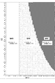
図8は、画像形成装置内部の環境条件により設定されるセラミックヒータ33の温度に基づいて、冷却ファン60の風量を切り替える制御に使用する、環境テーブルの一例である。
FIG. 8 is an example of an environment table used for control for switching the air volume of the cooling
本実施例においては、環境条件を温度と湿度により領域D、領域E、領域Fの3つの領域に分割し、領域ごとにセラミックヒータ33の温度を設定している。
領域Dは、低温環境での定着性を満足させるためにセラミックヒータ33の設定温度を190℃と他の環境領域より高くしている。そのためシートSから発生する水蒸気量が多くなり結露が発生しやすい。しかし領域Dは画像形成装置内の温度が低くシートSが冷却されやすい。そのため積極的に送風してシートSを冷却しなくともカールが発生しにくい環境なので、冷却ファン60を停止することにより結露の発生を防止することが可能となる。
In this embodiment, the environmental conditions are divided into three regions, region D, region E, and region F, according to temperature and humidity, and the temperature of the
In the region D, the set temperature of the
領域Eは、領域DとFの中間の環境であり、セラミックヒータ33の設定温度を180℃としている。領域Eにおいては、シートSの温度とシートSから発生する水蒸気量は領域Dと領域Fの中間となる。領域Eにおいては冷却ファン60を半速(50%)で駆動することにより、送風でシートを冷却してカールの発生を抑制しつつ結露の発生を防止することが可能となる。
The region E is an environment between the regions D and F, and the set temperature of the
領域Fは、画像形成装置内が高温高湿の環境でありセラミックヒータ33の設定温度を150℃としている。領域Fは画像形成装置内の温度が高く結露が発生しにくい環境条件であり、さらにセラミックヒータ33の設定温度が低くシートSから発生する水蒸気量少ない。そのため冷却ファン60を全速で回しても結露の発生を防止することが可能となる。
In the region F, the inside of the image forming apparatus is a high temperature and high humidity environment, and the set temperature of the
図9のフローチャートに基づいて、本実施例における冷却方法について説明を行う。なお、図7のフローチャートと重複する部分については、説明を省略する。 Based on the flowchart of FIG. 9, the cooling method in a present Example is demonstrated. Note that a description of the same parts as those in the flowchart of FIG. 7 is omitted.
図9のフローチャートに基づいて、本実施例における冷却方法について説明を行う。図9の処理は、図3のROM123内に格納されているプログラムを、図3のCPU121が実行することにより実施される。
Based on the flowchart of FIG. 9, the cooling method in a present Example is demonstrated. The processing in FIG. 9 is implemented by the
図1のホストPCから図1の画像形成装置100へプリント指令として印刷ジョブが送信されると、図3のCPU121は、図3の環境センサS1により温度と湿度を検出する。(ステップS1101)
When a print job is transmitted as a print command from the host PC in FIG. 1 to the
次にステップS1101で検出した温度と湿度の環境条件を、図8のテーブルと照合する。(ステップS1102) Next, the environmental conditions of temperature and humidity detected in step S1101 are collated with the table of FIG. (Step S1102)
温度と湿度の照合結果から、環境条件が領域Eにある場合、図3のCPU121は、図3の共通駆動モータドライバD1を介して共通駆動モータを回転させると共に、図3の電圧制御ユニットU1を介して図3のセラミックヒータ33にステップS1101で検出した温度と湿度の環境条件応じて加熱を行う。
When the environmental condition is in the region E from the comparison result of the temperature and humidity, the
環境条件がDの領域であれば190℃(ステップS1103)、Eの領域であれば180℃(ステップS1104)、Fの領域であれば150℃(ステップS1105)に到達目標温度を設定し、設定した温度まで加熱動作を行う。 The target temperature is set to 190 ° C. (step S1103) if the environmental condition is D, 180 ° C. (step S1104) if it is E, and 150 ° C. (step S1105) if it is F. The heating operation is performed up to the specified temperature.
次に、図3のファンモータドライバD2を介して図3のファンモータM2を制御することにより、図5の冷却ファン60を駆動する。
環境条件が領域Dの場合は冷却ファン60の駆動を停止し(ステップS1106)、領域Eの場合は半速で駆動し(ステップS1107)、領域Fの場合は全速で駆動する(ステップS1108)。
Next, the cooling
When the environmental condition is the region D, the driving of the cooling
その後、シートSに画像を形成するプリント動作を行う(ステップS1109)。 Thereafter, a printing operation for forming an image on the sheet S is performed (step S1109).
印刷ジョブが終了した場合、定着部30の動作を停止し(ステップS1111)、冷却ファン60の動作を停止して(ステップS1112)、動作を終了する。印刷ジョブが未終了の場合は、ステップS1109へ戻り、引き続き処理を行う。
When the print job is finished, the operation of the fixing
なお、本実施例においては、温度と湿度の両方の検出結果に基づいて、冷却ファン60の動作を制御しているが、温度のみ、あるいは湿度のみの検出結果を用いて制御することも可能である。
In this embodiment, the operation of the cooling
また、環境条件の領域を領域D、領域E、領域Fの三分割とし、冷却ファン60の制御を全速駆動、半速駆動、停止の三段階としているが、さらに細かく分割して制御することも可能である。
In addition, the environmental condition region is divided into three regions, region D, region E, and region F, and the cooling
以上、説明したように、本発明の画像形成装置においては、環境条件とそれに基づいて設定するセラミックヒータ33の温度に応じて、結露の発生しやすい環境条件の場合に、風量が低減するように冷却ファン60の駆動制御を変更する。そのため、定着部30において加湿された空気は、レーザスキャナ23に到達しない。よって、露光装置としてのレーザスキャナで結露が発生することを防止することが可能となる。
As described above, in the image forming apparatus of the present invention, the air volume is reduced according to the environmental conditions and the temperature of the
本実施例は、実施例1に記載の画像形成装置に対して印刷枚数によって冷却方法を変更するものである。 In this embodiment, the cooling method is changed according to the number of printed sheets with respect to the image forming apparatus described in the first embodiment.
図10のフローチャートに基づいて、本実施例における冷却方法について説明を行う。なお、図7のフローチャートと重複する部分については、説明を省略する。また、実施例1と同一構成である部分については同一符号を付して、その説明を省略する。 Based on the flowchart of FIG. 10, the cooling method in a present Example is demonstrated. Note that a description of the same parts as those in the flowchart of FIG. 7 is omitted. In addition, the same reference numerals are given to portions having the same configuration as that of the first embodiment, and the description thereof is omitted.
図1の画像形成装置100が、図1のホストPCからプリント指令を受信後、図3のCPU121は、図1の定着部30の動作を開始し(S801)、図3の環境センサS1により温度と湿度の検出を行う(ステップS802)。
After the
次に、図3のCPU121は、図1のホストPCから送信された印刷ジョブの印刷枚数を判定する(ステップS804)。
Next, the
印刷枚数が50枚未満の場合は、ステップS805に進んで環境判定を行い、環境条件が図6のテーブルで領域Aであれば図1の冷却ファン60を半速駆動し(ステップS806)、環境条件が領域Bもしくは領域Cであれば図1の冷却ファン60を全速駆動する(ステップS806)。
If the number of printed sheets is less than 50, the process proceeds to step S805 to determine the environment. If the environmental condition is area A in the table of FIG. 6, the cooling
印刷枚数が50枚以上の場合は、ステップS808に進んで環境判定を行い、環境条件が図6のテーブルで領域Aもしくは領域Bであれば図1の冷却ファン60を半速駆動し(ステップS806)、環境条件が領域Cであれば図1の冷却ファン60を全速駆動する(ステップS806)。
If the number of printed sheets is 50 or more, the process proceeds to step S808 to determine the environment. If the environmental condition is area A or area B in the table of FIG. 6, the cooling
その後、シートSに画像を形成するプリント動作を行う。(ステップS810) Thereafter, a printing operation for forming an image on the sheet S is performed. (Step S810)
印刷ジョブが終了した場合、定着部30の動作を停止し(ステップS812)、冷却ファン60の動作を停止して(ステップS813)、動作を終了する。印刷ジョブが未終了の場合は、ステップS810へ戻り、引き続き処理を行う。
When the print job is finished, the operation of the fixing
以上の制御を行うことにより、印刷ジョブの枚数が多量で機内の湿度が上昇しやすい場合であっても、露光装置としてのレーザスキャナで結露が発生することを防止することが可能となる。 By performing the above control, it is possible to prevent dew condensation from occurring in the laser scanner as the exposure apparatus even when the number of print jobs is large and the humidity in the apparatus tends to increase.
なお、本実施例では実施例1に記載の画像形成装置において印刷枚数によって冷却方法を変更するものについて説明を行ったが、実施例2に記載の画像形成装置においても同様に組み合わせて実施可能である。 In this embodiment, the image forming apparatus described in the first embodiment is described in which the cooling method is changed depending on the number of printed sheets. However, the image forming apparatus described in the second embodiment can be similarly combined and implemented. is there.
本実施例は、実施例1に記載の画像形成装置に対して、画像形成を行うシートのサイズによって冷却方法を変更するものである。 In this embodiment, the cooling method is changed with respect to the image forming apparatus described in the first embodiment depending on the size of the sheet on which the image is formed.
図11のフローチャートに基づいて、本実施例における冷却方法について説明を行う。なお、図7、図10のフローチャートと重複する部分については、説明を省略する。また、実施例1と同一構成である部分については同一符号を付して、その説明を省略する。 Based on the flowchart of FIG. 11, the cooling method in a present Example is demonstrated. Note that a description of the same parts as those in the flowcharts of FIGS. 7 and 10 is omitted. In addition, the same reference numerals are given to portions having the same configuration as that of the first embodiment, and the description thereof is omitted.
図1の画像形成装置100が、図1のホストPCからプリント指令として印刷ジョブを受信後、図3のCPU121は、図1の定着部30の動作を開始し(S901)、図3の環境センサS1により温度と湿度の検出を行う(ステップS902)。
After the
次にステップS903に進み、環境条件の判定を行う。環境条件が図6のテーブルで領域Aあるいは領域Bにある場合は、ステップS904のシート幅判定を行う。 In step S903, the environmental condition is determined. If the environmental condition is in the area A or B in the table of FIG. 6, the sheet width is determined in step S904.
図3のCPU121は、図1のホストPCから送信された印刷ジョブの内容から、画像を形成するシートSの幅を判定する。シートSの幅がレターサイズの279mmを超える場合、図3のCPU121は図1の冷却ファン60を半速駆動する(ステップS905)。
The
ステップS903での環境条件判定で領域Cだった場合と、ステップS904でのシート幅判定でシートSの幅がレターサイズの279mm以下だった場合、ステップS906に進み、図3のCPU121は図1の冷却ファン60を全速駆動する。
If it is the region C in the environmental condition determination in step S903, and if the width of the sheet S is 279 mm or less of the letter size in the sheet width determination in step S904, the process proceeds to step S906, and the
シートSの通紙方向に対する幅が通紙領域より狭い場合、図1の定着部30において、シートSが定着ニップ部N2と接触する面積が減少し、シートSの加熱により発生する水蒸気も減少する。そのため、冷却ファン60を全速で駆動した場合であっても、レーザスキャナ23での結露は発生しない。
When the width of the sheet S in the sheet passing direction is narrower than the sheet passing region, the area where the sheet S contacts the fixing nip N2 is reduced in the fixing
以上の制御を行うことにより、画像を形成するシートのサイズに関わらず、露光装置としてのレーザスキャナで結露が発生することを防止することが可能となる。 By performing the above control, it is possible to prevent dew condensation from occurring in the laser scanner as the exposure apparatus regardless of the size of the sheet on which the image is formed.
なお、本実施例では実施例1に記載の画像形成装置において画像形成を行うシートのサイズによって冷却方法を変更するものについて説明を行ったが、他の実施例と組み合わせて実施することも可能である。
In the present exemplary embodiment, the description has been given of the image forming apparatus described in the first exemplary embodiment in which the cooling method is changed depending on the size of the sheet on which the image is formed. However, the present exemplary embodiment can be combined with other exemplary embodiments. is there.
1 ホストPC
20 画像形成部
23 レーザスキャナ
23a 防塵部材
30 定着部
40 シート排出部
50 シート再給送部
60 冷却ファン
100 画像形成装置
101 CPU
102 RAM
103 ROM
110 画像信号制御部
120 画像読取装置制御部
121 CPU
122 RAM
123 ROM
124 I/Oポート
130 画像形成装置制御部
140 操作・表示部
D1 共通駆動モータドライバ
D2 ファンモータドライバ
M1 共通駆動モータ
M2 ファンモータ
S1 環境センサ
1 Host PC
20
102 RAM
103 ROM
110
122 RAM
123 ROM
124 I /
Claims (5)
画像データに応じて像担持体を露光し、静電潜像を形成する露光手段と、
前記露光手段により静電潜像が形成された像担持体をトナー像に現像する現像手段と、
前記現像手段により現像されたトナー像を記録媒体に転写する転写手段と、
前記転写手段により記録媒体に転写されたトナー像を熱により記録媒体に定着させる定着手段と、
前記定着手段の周辺の空気が前記露光手段に向かう気流を発生させる送風手段と、
前記画像形成装置内部の温度を検出する温度検出手段と、
前記温度検出手段が所定温度未満の第1の温度範囲の温度を検出した時に前記定着手段を第1の設定温度とし、前記温度検出手段が前記所定温度以上の第2の温度範囲の温度を検出した時に前記定着手段を前記第1の設定温度よりも低い第2の設定温度とする温度設定手段と、
前記温度検出手段が前記第1の温度範囲の温度を検出したときに前記送風手段による送風を停止し、前記温度検出手段が前記第2の温度範囲の温度を検出したときに前記送風手段による送風を行う制御手段と、
を有することを特徴とする画像形成装置。 An image forming apparatus,
Exposure means for exposing the image carrier in accordance with image data to form an electrostatic latent image;
Developing means for developing an image carrier having an electrostatic latent image formed thereon by the exposure means into a toner image;
Transfer means for transferring the toner image developed by the developing means to a recording medium;
Fixing means for fixing the toner image transferred to the recording medium by the transfer means to the recording medium by heat;
An air blower for generating an airflow toward the exposure unit by air around the fixing unit;
Temperature detecting means for detecting the temperature inside the image forming apparatus;
When the temperature detection means detects a temperature in a first temperature range less than a predetermined temperature, the fixing means is set to a first set temperature, and the temperature detection means detects a temperature in a second temperature range equal to or higher than the predetermined temperature. A temperature setting means for setting the fixing means to a second set temperature lower than the first set temperature,
When the temperature detecting means detects the temperature in the first temperature range, the blowing by the blowing means is stopped, and when the temperature detecting means detects the temperature in the second temperature range, the blowing by the blowing means Control means for performing
An image forming apparatus comprising:
画像データに応じて像担持体を露光し、静電潜像を形成する露光手段と、
前記露光手段により静電潜像が形成された像担持体をトナー像に現像する現像手段と、
前記現像手段により現像されたトナー像を記録媒体に転写する転写手段と、
前記転写手段により記録媒体に転写されたトナー像を熱により記録媒体に定着させる定着手段と、
前記定着手段の周辺の空気が前記露光手段に向かう気流を発生させる送風手段と、
前記画像形成装置内部の温度を検出する温度検出手段と、
前記温度検出手段が所定温度未満の第1の温度範囲の温度を検出した時に前記定着手段を第1の設定温度とし、前記温度検出手段が前記所定温度以上の第2の温度範囲の温度を検出した時に前記定着手段を前記第1の設定温度よりも低い第2の設定温度とする温度設定手段と、
前記温度検出手段が前記第1の温度範囲の温度を検出したときには、前記温度検出手段が前記第2の温度範囲の温度を検出したときよりも前記送風手段による風量を低減する制御手段と、
を有することを特徴とする画像形成装置。 An image forming apparatus,
Exposure means for exposing the image carrier in accordance with image data to form an electrostatic latent image;
Developing means for developing an image carrier having an electrostatic latent image formed thereon by the exposure means into a toner image;
Transfer means for transferring the toner image developed by the developing means to a recording medium;
Fixing means for fixing the toner image transferred to the recording medium by the transfer means to the recording medium by heat;
An air blower for generating an airflow toward the exposure unit by air around the fixing unit;
Temperature detecting means for detecting the temperature inside the image forming apparatus;
When the temperature detection means detects a temperature in a first temperature range less than a predetermined temperature, the fixing means is set to a first set temperature, and the temperature detection means detects a temperature in a second temperature range equal to or higher than the predetermined temperature. A temperature setting means for setting the fixing means to a second set temperature lower than the first set temperature,
When the temperature detection means detects the temperature of the first temperature range, the control means for reducing the air volume by the blower means than when the temperature detection means detects the temperature of the second temperature range;
An image forming apparatus comprising:
前記制御手段は、前記印刷枚数が多くなることに応じて、風量が低減するように前記送風手段の駆動条件を変更することを特徴とする請求項1乃至請求項3のいずれか1項に記載の画像形成装置。 A print number detecting unit for detecting the number of prints of the print job;
The said control means changes the drive condition of the said ventilation means so that an air volume may reduce according to the said number of printed sheets increasing, The said any one of Claim 1 thru | or 3 characterized by the above-mentioned. Image forming apparatus.
前記制御手段は、前記シートサイズが大きくなることに応じて、風量が低減するように前記送風手段の駆動条件を変更することを特徴とする請求項1乃至請求項4のいずれか1項に記載の画像形成装置。 A sheet size detecting means for detecting the size of the sheet forming the image;
The said control means changes the drive condition of the said ventilation means so that an air volume may reduce according to the said sheet | seat size becoming large, The any one of Claim 1 thru | or 4 characterized by the above-mentioned. Image forming apparatus.
Priority Applications (2)
| Application Number | Priority Date | Filing Date | Title |
|---|---|---|---|
| US14/863,951 US9523959B2 (en) | 2014-09-30 | 2015-09-24 | Image forming apparatus with control unit configured to reduce the air blown by a blower unit reaching an exposure unit |
| CN201510638869.3A CN105467803B (en) | 2014-09-30 | 2015-09-29 | Imaging device |
Applications Claiming Priority (2)
| Application Number | Priority Date | Filing Date | Title |
|---|---|---|---|
| JP2014201075 | 2014-09-30 | ||
| JP2014201075 | 2014-09-30 |
Publications (3)
| Publication Number | Publication Date |
|---|---|
| JP2016071331A JP2016071331A (en) | 2016-05-09 |
| JP2016071331A5 JP2016071331A5 (en) | 2016-10-13 |
| JP6261545B2 true JP6261545B2 (en) | 2018-01-17 |
Family
ID=55864637
Family Applications (1)
| Application Number | Title | Priority Date | Filing Date |
|---|---|---|---|
| JP2015144069A Active JP6261545B2 (en) | 2014-09-30 | 2015-07-21 | Image forming apparatus |
Country Status (1)
| Country | Link |
|---|---|
| JP (1) | JP6261545B2 (en) |
Families Citing this family (2)
| Publication number | Priority date | Publication date | Assignee | Title |
|---|---|---|---|---|
| JP6921552B2 (en) * | 2017-02-24 | 2021-08-18 | キヤノン株式会社 | Image forming device |
| JP2018205659A (en) * | 2017-06-09 | 2018-12-27 | キヤノン株式会社 | Image formation apparatus |
Family Cites Families (2)
| Publication number | Priority date | Publication date | Assignee | Title |
|---|---|---|---|---|
| JPS63231363A (en) * | 1987-03-20 | 1988-09-27 | Canon Inc | Image forming device |
| US8045879B2 (en) * | 2008-09-11 | 2011-10-25 | Xerox Corpoation | Methods for controlling environmental conditions in an electrophotographic apparatus and a corresponding electrophotographic apparatus |
-
2015
- 2015-07-21 JP JP2015144069A patent/JP6261545B2/en active Active
Also Published As
| Publication number | Publication date |
|---|---|
| JP2016071331A (en) | 2016-05-09 |
Similar Documents
| Publication | Publication Date | Title |
|---|---|---|
| JP6639251B2 (en) | Image forming device | |
| US9523959B2 (en) | Image forming apparatus with control unit configured to reduce the air blown by a blower unit reaching an exposure unit | |
| JP6261545B2 (en) | Image forming apparatus | |
| JP6274133B2 (en) | Image forming apparatus | |
| CN106919033B (en) | Image forming apparatus with a toner supply device | |
| JP6921552B2 (en) | Image forming device | |
| US11112740B2 (en) | Image forming apparatus | |
| US10895832B2 (en) | Image forming apparatus capable of suppressing damage to a fixing member while maintaining productivity | |
| JP2008122513A (en) | Image forming apparatus | |
| JP2018036525A (en) | Image forming apparatus and control method | |
| US10042322B2 (en) | Image formation system | |
| US11119429B2 (en) | Image forming apparatus | |
| JP6170861B2 (en) | Image forming apparatus | |
| JP5879411B2 (en) | Fixing apparatus and image forming apparatus | |
| JP2011158809A (en) | Fixing device and image forming apparatus | |
| JP7180361B2 (en) | Fixing device, image forming device and control method | |
| JP7409862B2 (en) | Image forming device and image fixing method | |
| JP2018049097A (en) | Image forming apparatus | |
| JP6154771B2 (en) | Image forming apparatus | |
| JP2018025598A (en) | Image forming apparatus, method for controlling image forming apparatus, and program for controlling image forming apparatus | |
| JP2018039600A (en) | Image formation device | |
| JP6477599B2 (en) | Image forming apparatus and conveyance control method | |
| JP2020086370A (en) | Fixing device, image forming apparatus, and blowing control method | |
| JP2013041149A (en) | Image forming device and image forming method | |
| JP2020046689A (en) | Image forming apparatus |
Legal Events
| Date | Code | Title | Description |
|---|---|---|---|
| A521 | Request for written amendment filed |
Free format text: JAPANESE INTERMEDIATE CODE: A523 Effective date: 20160825 |
|
| A621 | Written request for application examination |
Free format text: JAPANESE INTERMEDIATE CODE: A621 Effective date: 20160825 |
|
| A977 | Report on retrieval |
Free format text: JAPANESE INTERMEDIATE CODE: A971007 Effective date: 20170531 |
|
| A131 | Notification of reasons for refusal |
Free format text: JAPANESE INTERMEDIATE CODE: A131 Effective date: 20170606 |
|
| A521 | Request for written amendment filed |
Free format text: JAPANESE INTERMEDIATE CODE: A523 Effective date: 20170728 |
|
| A131 | Notification of reasons for refusal |
Free format text: JAPANESE INTERMEDIATE CODE: A131 Effective date: 20170925 |
|
| A521 | Request for written amendment filed |
Free format text: JAPANESE INTERMEDIATE CODE: A523 Effective date: 20171124 |
|
| TRDD | Decision of grant or rejection written | ||
| A01 | Written decision to grant a patent or to grant a registration (utility model) |
Free format text: JAPANESE INTERMEDIATE CODE: A01 Effective date: 20171207 |
|
| A61 | First payment of annual fees (during grant procedure) |
Free format text: JAPANESE INTERMEDIATE CODE: A61 Effective date: 20171212 |
|
| R150 | Certificate of patent or registration of utility model |
Ref document number: 6261545 Country of ref document: JP Free format text: JAPANESE INTERMEDIATE CODE: R150 |
|
| R250 | Receipt of annual fees |
Free format text: JAPANESE INTERMEDIATE CODE: R250 |
|
| R250 | Receipt of annual fees |
Free format text: JAPANESE INTERMEDIATE CODE: R250 |
|
| R250 | Receipt of annual fees |
Free format text: JAPANESE INTERMEDIATE CODE: R250 |