JP6261313B2 - Developing device, process cartridge, and image forming apparatus - Google Patents
Developing device, process cartridge, and image forming apparatusInfo
- Publication number
- JP6261313B2 JP6261313B2 JP2013255203A JP2013255203A JP6261313B2 JP 6261313 B2 JP6261313 B2 JP 6261313B2 JP 2013255203 A JP2013255203 A JP 2013255203A JP 2013255203 A JP2013255203 A JP 2013255203A JP 6261313 B2 JP6261313 B2 JP 6261313B2
- Authority
- JP
- Japan
- Prior art keywords
- developer
- supply roller
- sheet member
- stirring
- developing device
- Prior art date
- Legal status (The legal status is an assumption and is not a legal conclusion. Google has not performed a legal analysis and makes no representation as to the accuracy of the status listed.)
- Active
Links
Images


Classifications
-
- G—PHYSICS
- G03—PHOTOGRAPHY; CINEMATOGRAPHY; ANALOGOUS TECHNIQUES USING WAVES OTHER THAN OPTICAL WAVES; ELECTROGRAPHY; HOLOGRAPHY
- G03G—ELECTROGRAPHY; ELECTROPHOTOGRAPHY; MAGNETOGRAPHY
- G03G15/00—Apparatus for electrographic processes using a charge pattern
- G03G15/06—Apparatus for electrographic processes using a charge pattern for developing
- G03G15/08—Apparatus for electrographic processes using a charge pattern for developing using a solid developer, e.g. powder developer
- G03G15/0822—Arrangements for preparing, mixing, supplying or dispensing developer
- G03G15/0887—Arrangements for conveying and conditioning developer in the developing unit, e.g. agitating, removing impurities or humidity
- G03G15/0889—Arrangements for conveying and conditioning developer in the developing unit, e.g. agitating, removing impurities or humidity for agitation or stirring
-
- G—PHYSICS
- G03—PHOTOGRAPHY; CINEMATOGRAPHY; ANALOGOUS TECHNIQUES USING WAVES OTHER THAN OPTICAL WAVES; ELECTROGRAPHY; HOLOGRAPHY
- G03G—ELECTROGRAPHY; ELECTROPHOTOGRAPHY; MAGNETOGRAPHY
- G03G15/00—Apparatus for electrographic processes using a charge pattern
- G03G15/06—Apparatus for electrographic processes using a charge pattern for developing
- G03G15/08—Apparatus for electrographic processes using a charge pattern for developing using a solid developer, e.g. powder developer
- G03G15/0806—Apparatus for electrographic processes using a charge pattern for developing using a solid developer, e.g. powder developer on a donor element, e.g. belt, roller
- G03G15/0808—Apparatus for electrographic processes using a charge pattern for developing using a solid developer, e.g. powder developer on a donor element, e.g. belt, roller characterised by the developer supplying means, e.g. structure of developer supply roller
Landscapes
- Physics & Mathematics (AREA)
- General Physics & Mathematics (AREA)
- Dry Development In Electrophotography (AREA)
Description
本発明は、電子写真複写機、電子写真プリンタ等の画像形成装置に着脱可能な現像装置及びプロセスカートリッジ等に関するものである。特に、現像装置における現像剤の撹拌に関するものである。 The present invention relates to a developing device and a process cartridge that can be attached to and detached from an image forming apparatus such as an electrophotographic copying machine or an electrophotographic printer. In particular, the present invention relates to the stirring of the developer in the developing device.
従来、現像装置は、現像剤を担持し像担持体に現像剤像を形成する現像剤担持体を少なくとも備える。さらに、その現像剤担持体に接触して現像剤を供給する現像剤供給ローラと、現像剤担持体上の現像剤層を規制する規制部材と、現像剤を収容する現像枠体、などから構成されている。 Conventionally, a developing device includes at least a developer carrier that carries a developer and forms a developer image on the image carrier. And a developer supply roller for supplying the developer in contact with the developer carrying member, a regulating member for regulating the developer layer on the developer carrying member, a developing frame housing the developer, and the like. Has been.
現像枠体には現像剤の凝集や劣化を防止するため現像剤撹拌手段が回転可能に設けられているものがある(特許文献1、2)。 Some developing frame bodies are provided with a developer agitating means in a rotatable manner to prevent aggregation and deterioration of the developer (Patent Documents 1 and 2).
しかしながら、現像剤撹拌手段は現像剤担持体及び現像剤供給ローラから離れて配置されるため、現像剤供給ローラの近傍の凝集した現像剤あるいは劣化した現像剤を撹拌しきれない。このため、現像剤の供給が不安定になり画像の濃度にムラが発生する恐れがあった(特許文献1参照)。 However, since the developer agitation means is disposed away from the developer carrier and the developer supply roller, the agglomerated developer or the deteriorated developer in the vicinity of the developer supply roller cannot be agitated. For this reason, the supply of the developer becomes unstable, and there is a possibility that the density of the image is uneven (see Patent Document 1).
そこで、本発明は、現像剤供給ローラの近傍の現像剤の循環を良好にする現像剤撹拌手段を備えた現像装置を提供することにある。 SUMMARY OF THE INVENTION Accordingly, the present invention is to provide a developing device provided with a developer agitating means for improving the circulation of the developer in the vicinity of the developer supply roller.
そこで、本発明の現像装置は、
現像剤を収納するための現像剤枠体と、
現像剤を担持するための現像剤担持体と、
回転可能に支持され、前記現像剤担持体と接触するとともに、前記現像剤担持体に現像剤を供給する連続発泡体の弾性層を有する現像剤供給ローラと、
現像剤を撹拌するためのシート部材と、前記シート部材の一端が固定され前記現像剤供給ローラと同一回転方向に回転可能な攪拌軸部材と、を有し、前記現像剤供給ローラよりも重力方向の上方の所定領域の少なくとも一部を通過しながら撹拌する撹拌手段と、
前記現像枠体に設けられ、前記シート部材で搬送される現像剤の移動を規制する規制部と、を有し、
前記所定領域は、重力方向において前記現像剤供給ローラの上方から前記現像剤供給ローラの半径分までの長さを備え、
前記攪拌軸部材の軸方向に沿って見たとき、前記規制部は、重力方向で前記撹拌手段の回転中心を通る直線で分割される2つの領域のうち、前記シート部材が重力方向に沿って移動する一方の領域に設けられ、
前記弾性層が前記現像剤担持体と接触することで自然状態から弾性変形する領域は、前記現像剤供給ローラの中心と前記現像剤担持体の中心を結んだ直線よりも前記撹拌手段側に位置することを特徴とする。
Therefore, the developing device of the present invention is
A developer frame for storing the developer;
A developer carrier for carrying the developer;
A developer supply roller that is rotatably supported and has an elastic layer of continuous foam that contacts the developer carrier and supplies the developer to the developer carrier;
A sheet member for stirring the developer; and a stirring shaft member having one end fixed to the sheet member and capable of rotating in the same rotational direction as the developer supply roller. Stirring means for stirring while passing through at least a part of the predetermined region above,
A regulating portion that is provided on the developing frame and regulates the movement of the developer conveyed by the sheet member;
The predetermined area includes a length from above the developer supply roller to a radius of the developer supply roller in the direction of gravity,
When viewed along the axial direction of the agitation shaft member, the restricting portion has two regions divided by a straight line passing through the rotation center of the agitation means in the direction of gravity, and the sheet member is aligned along the direction of gravity. Provided in one area to move,
The region where the elastic layer is elastically deformed from the natural state by contacting the developer carrier is located closer to the stirring means than the straight line connecting the center of the developer supply roller and the center of the developer carrier. It is characterized by doing.
また、他の本発明の現像装置は、
現像剤を収納するための現像剤枠体と、
現像剤を担持するための現像剤担持体と、
回転可能に支持され、前記現像剤担持体と接触するとともに、前記現像剤担持体に現像剤を供給する連続発泡体の弾性層を有する現像剤供給ローラと、
現像剤を撹拌するためのシート部材と、前記シート部材の一端が固定され前記現像剤供給ローラと同一回転方向に回転可能な攪拌軸部材と、を有し、前記現像剤供給ローラよりも重力方向の上方に設けられている撹拌手段と、
前記現像枠体に設けられ、前記シート部材で搬送される現像剤の移動を規制する規制部と、を有し、
前記弾性層が前記現像剤担持体と接触することで自然状態から弾性変形する領域は、前記現像剤供給ローラの中心と前記現像剤担持体の中心を結んだ直線よりも前記撹拌手段側に位置し、
前記攪拌軸部材の軸方向に沿って見たとき、前記規制部は、重力方向で前記撹拌手段の回転中心を通る直線で分割される2つの領域のうち、前記シート部材が重力方向に沿って移動する一方の領域に設けられ、
前記シート部材は、前記撹拌手段が回転する際に前記現像剤供給ローラと接触するように配置されていることを特徴とする。
In addition, another developing device of the present invention includes:
A developer frame for storing the developer;
A developer carrier for carrying the developer;
A developer supply roller that is rotatably supported and has an elastic layer of continuous foam that contacts the developer carrier and supplies the developer to the developer carrier;
A sheet member for stirring the developer; and a stirring shaft member having one end fixed to the sheet member and capable of rotating in the same rotational direction as the developer supply roller. A stirring means provided above,
A regulating portion that is provided on the developing frame and regulates the movement of the developer conveyed by the sheet member;
The region where the elastic layer is elastically deformed from the natural state by contacting the developer carrier is located closer to the stirring means than the straight line connecting the center of the developer supply roller and the center of the developer carrier. And
When viewed along the axial direction of the agitation shaft member, the restricting portion has two regions divided by a straight line passing through the rotation center of the agitation means in the direction of gravity, and the sheet member is aligned along the direction of gravity. Provided in one area to move,
The sheet member is disposed so as to come into contact with the developer supply roller when the stirring unit rotates.
さらに、本発明は、プロセスカートリッジや画像形成装置を提供するものである。 Furthermore, the present invention provides a process cartridge and an image forming apparatus.
以上、説明したように、本発明によれば、現像剤供給ローラの近傍の現像剤の循環を良好に保ち、現像剤を現像剤担持体に安定して供給することが可能であり、高品位の画像を提供することができる。 As described above, according to the present invention, it is possible to maintain a good circulation of the developer in the vicinity of the developer supply roller, and to stably supply the developer to the developer carrying member. Images can be provided.
以下に、図面および実施例を参照して、この発明を実施するための形態を例示的に詳しく説明する。ただし、この実施例に記載されている構成部品の機能、材質、形状、機能、その相対配置などは、特に特定的な記載がない限りは、この発明の範囲をそれらのみに限定する趣旨のものではない。また、以下の説明で一度説明した部材についての材質、形状などは、特に改めて記載しない限り初めの説明と同様のものである。 Hereinafter, exemplary embodiments for carrying out the present invention will be described in detail with reference to the drawings and examples. However, the functions, materials, shapes, functions, relative arrangements, etc. of the components described in this embodiment are intended to limit the scope of the present invention only to those unless otherwise specified. is not. Further, the materials, shapes, etc. of the members once described in the following description are the same as those in the first description unless otherwise described.
以下、本発明に係る現像装置及びプロセスカートリッジを図面に則して説明する。 A developing device and a process cartridge according to the present invention will be described below with reference to the drawings.
図4は、現像装置38の外観斜視図を示した図である。図4(a)は、組み立てられた状態の現像装置38の外観斜視図であり、図4(b)は現像装置38の分解斜視図である。
FIG. 4 is an external perspective view of the developing
以下の説明において、長手方向Fとは図4に示すように、現像装置38の長辺の方向と一致している。また、長手方向Fにおいて、駆動ギア(現像ローラギア69、供給ローラギア70、現像入力ギア68、撹拌ギア71)が設けられている一端側を駆動側、他端側を非駆動側と称する。
In the following description, the longitudinal direction F coincides with the direction of the long side of the developing
図2は、本発明を適用できるプロセスカートリッジAの断面図である。また、図3は、本発明を適用できる画像形成装置Bの断面図を図示する。 FIG. 2 is a sectional view of a process cartridge A to which the present invention can be applied. FIG. 3 is a sectional view of an image forming apparatus B to which the present invention can be applied.
[プロセスカートリッジの構成概要]
プロセスカートリッジAは、像担持体としての感光体ドラム11と、感光体ドラム11に作用するプロセス手段を備えたものである。ここでプロセス手段としては、例えば感光体ドラム11の表面を帯電させる帯電手段、感光体ドラム11に現像剤像を形成する現像装置38、感光体ドラム11表面に残留した現像剤T(トナー、キャリア等を含む)を除去するためのクリーニング手段がある。
[Outline of process cartridge configuration]
The process cartridge A is provided with a
本実施形態のプロセスカートリッジAは、図2に示すように感光体ドラム11の周囲に帯電手段である帯電ローラ12、そしてクリーニング手段として弾性を有するクリーニングブレード14を有するクリーナユニット24を備えている。また、プロセスカートリッジAは、現像装置38を備えている。プロセスカートリッジAは、クリーナユニット24と現像装置38とを一体とし、図3に示すように画像形成装置Bに対して、着脱可能に構成されている。現像装置38は、現像手段である現像剤担持体としての現像ローラ13と現像ブレード15、現像ローラ13へ現像剤Tを供給する現像剤供給ローラ23(以下、供給ローラとする)、撹拌手段21を有する。
As shown in FIG. 2, the process cartridge A according to this embodiment includes a
[画像形成装置の構成概要]
このプロセスカートリッジAは図3に示すような画像形成装置Bに装着されて画像形成に用いられる。画像形成は画像形成装置Bの下部に装着されたシートカセット6から搬送ローラ7によってシートSを搬送し、このシートSの搬送と同期して、感光体ドラム11に露光装置8から選択的な露光をして潜像を形成する。現像剤Tは、供給ローラ23によって現像ローラ13に供給され、現像ブレード15により現像ローラ13表面に薄層が形成される。現像ローラ13に画像形成装置Bから供給される現像バイアスを印加する事によって、潜像に応じて現像剤Tを供給し、潜像を現像し現像剤像を形成する。この現像剤像を転写ローラ9へのバイアス電圧印加によって搬送されるシートSに転写する。シートSは定着装置10へ搬送され画像定着し、排紙ローラ1によって画像形成装置Bの上部の排紙部3に排出される。
[Configuration overview of image forming apparatus]
The process cartridge A is mounted on an image forming apparatus B as shown in FIG. 3 and used for image formation. In image formation, a sheet S is conveyed by a conveying
本実施例においては、画像形成装置Bに対して1つのプロセスカートリッジAを装着する構成を示している。しかし、これに限らず、フルカラー画像に対応したイエロー色、マゼンタ色、シアン色、ブラック色の現像剤を収容した複数のプロセスカートリッジAを装着できる構成でも良い。 In this embodiment, a configuration in which one process cartridge A is mounted on the image forming apparatus B is shown. However, the present invention is not limited to this, and a configuration in which a plurality of process cartridges A containing developer of yellow, magenta, cyan, and black corresponding to a full color image may be mounted.
[現像装置の構成概要]
次に、現像装置38の構成について図2、図4を用いて説明する。図2はプロセスカートリッジAの断面図であり、図4は現像装置38の外観斜視図である。現像装置38は、現像ローラ13、供給ローラ23、現像ブレード15、現像枠体40、駆動側軸受44、
非駆動側軸受45、現像カバー32、撹拌手段21などで構成されている。現像ローラ13は弾性層13aと芯金13jから成り、供給ローラ23は弾性層23aと芯金23jから成る。
[Overview of development device configuration]
Next, the configuration of the developing
The non-driving side bearing 45, the developing
ここで、供給ローラの径は、11mmであり、半径は5.5mmになる。芯金23jの径は、4mmであり、半径は2mmになる。供給ローラ23の弾性層23aはウレタン材質の発泡スポンジ層であり、発泡スポンジ層内の隣り合うセル各々が所望の割合で連なった連続発泡体構造である。また、弾性層23aの厚みtは3.5mmである。さらに、発泡スポンジ層の外部と内部の気圧が平衡状態となる時に発泡スポンジ層を通過する空気の量としての表面通気量は、1.5リットル/minである。
Here, the diameter of the supply roller is 11 mm, and the radius is 5.5 mm. The diameter of the cored
本実施例では、現像ローラ13の芯金13jの中心と供給ローラ23の芯金23jの中心との距離(以下、中心間距離)を9.5mmとする。そして、現像ローラ13の表面が供給ローラ23の発泡スポンジ層23aを、1.0mmほどの侵入量で押し込むように設置する。ここで侵入量とは、芯金13jの中心と芯金23jの中心間を結ぶ線分上で、供給ローラ23の発泡スポンジ層23aの外径と現像ローラ13の弾性層13aの外径の和を2で割って上記中心間距離を差し引いた長さである。
In this embodiment, the distance between the center of the
撹拌手段21は、撹拌軸部材20と可撓性部材としてのシート部材19から成り、シート部材19は一端側を撹拌軸部材20に結合され、他端側は自由端19sを有する。また、撹拌軸部材20の中心からシート部材19の自由端側の端面までの距離L1は、撹拌軸部材20の中心から供給ローラ23の弾性層23aの表面までの距離L2よりも長い。さらに、シート部材19の材質はポリエチレンテレフタレート(PET)で、厚みは38μmである。但し、供給ローラ23の弾性層23a、及びシート部材19の材質、厚みに関しては、これに限ったものでは無く適宜選択可能である。現像枠体40は、供給ローラ23に供給する現像剤Tを収納する現像剤収納室46及び現像ローラ13の弾性層13aの表面に形成された現像剤Tの層厚を一定に規制する現像ブレード15を有する。
The stirring means 21 includes a stirring
また、図4に示すように、現像ローラ13は、芯金13jが駆動側軸受44の穴部44h及び非駆動側軸受45の穴部45hと嵌合して回転可能に支持されている。さらに、供給ローラ23は、芯金23jが駆動側軸受44の穴部44i及び非駆動側軸受45の穴部45iと嵌合して、回転可能に支持されている。さらに、撹拌手段21は、撹拌軸部材20と駆動側軸受44の穴部44k及び非駆動側軸受45の穴部45kと嵌合して、回転可能に支持されている。
Further, as shown in FIG. 4, the developing
そして、長手方向Fにおいて、現像ローラ13の駆動側端部には、現像ローラ13に回転駆動力を伝達する為の現像ローラギア69が回転可能に設けられている。長手方向Fにおいて、供給ローラ23の駆動側端部には、供給ローラ23に回転駆動力を伝達する為の供給ローラギア70が回転可能に設けられている。長手方向Fにおいて撹拌軸部材20の駆動側端部には、撹拌手段21に回転駆動力を伝達する為の撹拌ギア71が回転可能に設けられている。さらに、駆動側軸受44の長手方向Fにおける外側には、現像ローラギア69、供給ローラギア70、撹拌ギア71に回転駆動力を伝達する現像入力ギア68が設けられている。そして、現像カバー部材32が、現像ローラギア69や供給ローラギア70、撹拌ギア71、現像入力ギア68を覆うように、駆動側軸受44の長手方向Fにおける外側に固定されている。
In the longitudinal direction F, a developing
さらに、図4に示すように、長手方向Fにおける駆動側の現像カバー部材32には円筒部32bが設けられている。そして、円筒部32bの内側の開口32cからは、現像入力ギア68の駆動伝達部68aが露出する。ここで、現像入力ギア68の駆動伝達部68aは、プロセスカートリッジAが画像形成装置Bに装着された際に、不図示の本体駆動伝達部材と係合する。そして、画像形成装置Bに設けられた駆動モータ(不図示)からの矢印Oの方向の回転駆動力が伝達される構成となっている。画像形成装置Bから現像入力ギア68へ入力された回転駆動力は、現像ローラギア69を介して現像ローラ13へ、供給ローラギア70を介して供給ローラ23へ、撹拌ギア71を介して撹拌手段21へ伝達される構成となっている。その結果、図2に示すように、現像ローラ13は矢印D方向、供給ローラ23は矢印C方向、撹拌手段は矢印E方向に回転する。
Further, as shown in FIG. 4, the developing
[現像装置内の現像剤循環について]
図5は、画像形成動作中の現像ローラ13、供給ローラ23付近の拡大模式図である。ここで、図5(a)を用いて、供給ローラ23による現像ローラ13への現像剤の供給について説明をする。前述した通り、現像ローラ13は矢印D方向、供給ローラ23は矢印C方向の同一方向に回転する。さらに、供給ローラ23は、現像ローラ13に一定の侵入量(本実施例ではδ=1mm)で侵入し、弾性変形した状態で回転している。このとき、現像ローラ13に対する供給ローラ23の周速比は0.8程度に設定されている。
[About developer circulation in the developing device]
FIG. 5 is an enlarged schematic view of the vicinity of the developing
そして、現像剤収納室46に収容された現像剤Tに覆われた供給ローラ23は、矢印C方向に回転することによって、現像ローラ13との接触部23dにおいて弾性変形していた弾性層23aが解放される。その弾性層23aが解放される直後の領域Uにおいて、現像ローラ13と接触して弾性変形(または圧縮変形)していた弾性層23aが自然状態に復元する。自然状態に復元することによって、弾性層23a内のセルが開く作用がある為、セルの内部に吸気が行われると共に現像剤Tが矢印T1の方向に吸い込まれる。さらに、供給ローラ23の回転方向(矢印C方向)において、現像ローラ13に接触する直前の領域Wでは、自然状態であった弾性層23aが弾性変形(または圧縮変形)する為、弾性層23aのセルが閉じる作用がある。さらに、領域Wは、供給ローラ23の中心と現像剤担持体の中心を結んだ直線J5よりも撹拌手段側に設けられている。その為、領域Wにおいては、弾性層23aのセルに保持していた現像剤Tを矢印T2方向に吐き出す。即ち、供給ローラ23は、領域Uにおいて現像剤Tを吸い込み、現像剤Tを弾性層23aのセルに保持した状態で回転し、領域Wにおいて保持していた現像剤Tを吐き出すことによって、現像ローラ13に現像剤Tを供給する作用がある。従って、現像ローラ13に連続的に現像剤Tを供給する為に供給ローラ23に現像剤Tを保持させるには、領域Uに現像剤Tを搬送することが最も効率が良い。
The
次に、図5(b)(c)を用いて、供給ローラ23付近の現像剤Tの循環(流れ)について説明する。
Next, the circulation (flow) of the developer T near the
図5(b)に示すように、領域Wにおいて、供給ローラ23から現像剤が矢印T2の方向に吐き出される。それに伴い、供給ローラ23の上方で弾性層23aから一定距離離れた領域Zに既にあった現像剤Tは供給ローラ23から吐き出された現像剤Tによって押しだされる為、矢印Z1方向に移動する。ここで、画像形成時において供給ローラ23は常に回転しており、領域Wにおける供給ローラ23から現像剤Tが吐き出される現象は連続的に発生している為、矢印Z1方向への現像剤Tの移動が連続的に発生する。その結果、供給ローラ23付近においては矢印Z1方向の現像剤Tの循環が発生する。この矢印Z1方向の現像剤Tの循環により、現像剤Tは連続的に供給ローラ23が現像剤Tを吸い込む領域Uに供給される。即ち、矢印Z1方向の現像剤Tの循環により、供給ローラ23の現像剤Tの吸い込み部である領域Uに現像剤Tを移動させる。その為には、供給ローラ23まわりの現像剤Tはある一定以上の流動性を保つ必要があり、現像剤Tの密度は必要以上に高くない方が望ましい。
As shown in FIG. 5B, in the region W, the developer is discharged from the
一方、図5(c)に示すように、供給ローラ23の表面の薄層領域εにおいては、現像剤Tと供給ローラ23との摩擦によって、供給ローラ23の回転方向(矢印C方向)に現像剤Tが搬送される。その結果、供給ローラ23の表面の薄層領域εにおいては、供給ローラ23の回転方向(矢印C方向)の現像剤Tの循環が発生する。
On the other hand, as shown in FIG. 5C, in the thin layer region ε on the surface of the
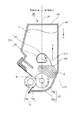
[撹拌手段の回転と作用]
図6は現像装置38の断面図である。現像剤収納室46と、撹拌軸部材20とシート部材19で構成された撹拌手段21とは、供給ローラ23よりも重力方向Gの上方に設けられ、供給ローラ23と同一回転方向に回転する(矢印E方向)。供給ローラ23の回転数に対する撹拌手段の回転数比は約0.09に設定されている。ここで、供給ローラ23よりも重力方向Gの上方とは、供給ローラ23の中心を通る水平線J23よりも上方であることを意味する。ここで、撹拌手段21の回転中心21cを通り重力方向Gの直線J4で分割される2つの領域において、シート部材19の自由端19sが重力方向Gとは抗する方向に回転する領域を領域J1、もう一方を領域J2とする。
[Rotation and action of stirring means]
FIG. 6 is a sectional view of the developing
ここで、現像剤収納室46は供給ローラ23の重力方向Gの上方に設けられており、現像剤Tの供給ローラ23への供給方向は重力方向Gとなる。その為、領域Zにおいて、供給ローラ23よりも重力方向Gの上方にある現像剤Tの自重による圧力が作用する為、供給ローラ23の上方の領域Zの現像剤Tが高密度になりやすい。ここで、図6は、撹拌手段21のシート部材19の自由端19sが領域J1の領域側(又は領域内)にあるときの現像装置38の断面図である。このとき、撹拌手段21のシート部材19が現像剤Tを搬送する方向は、重力方向Gに抗する方向(矢印V方向)である。その結果、撹拌手段21は、現像剤Tの自重による圧力を軽減する方向に現像剤Tを搬送する為、領域Zにおける現像剤Tの密度が必要以上に高くなることを防止できる。従って、供給ローラ23周辺(領域Z)の現像剤Tの良好な循環を保つことができる。
Here, the
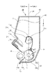
次に領域J2における撹拌手段21の動作と作用について説明する。図7は図6に対して撹拌手段21が一定位相回転した状態の現像装置38の断面図である。図7に示すように、領域J2における現像枠体40の内壁40bには、撹拌手段21が回転する過程において、シート部材19の自由端19sと接するシート部材規制部2(以下、規制部とする)が設けられている。規制部2は長手方向に連続的に伸びており、シート部材19と接触することでシート部材19を弾性変形させる規制面2aを有する。さらに、規制面2aは、撹拌手段21の回転方向(矢印E方向)における下流側にシート部材19の弾性変形を開放する解放点2bを有する。尚、本実施例のおいては、現像枠体40と一体形状であるが、別体で現像枠体40に接着などで結合された構成でも良い。本実施例においては、規制面2aに、規制面2aと直交方向から見て、切り欠き形状や開口は無いが、規制面の一部に開口や切り欠きがある構成でもよい。ここで、解放点2bと供給ローラ23の中心を結ぶ直線を直線Rする。また、解放点2bを通り、撹拌手段21の回転中心21cと同心の円Kにおける解放点上2bの接線を直線Qとする。また、撹拌手段21の回転中心21cと解放点2bを結ぶ直線を直線J3とする。この時、直線Qと供給ローラ23の弾性層23aの表面との交点Mは、直線Rと供給ローラ23の弾性層23aとの交点Nよりも供給ローラ23の回転方向(矢印C方向)において、上流側にある。
Next, the operation and action of the stirring means 21 in the region J2 will be described. FIG. 7 is a cross-sectional view of the developing
図7に示すように、撹拌手段21の回転方向(矢印E方向)において、撹拌手段21のシート部材19の自由端19sは、領域J2における直線J4から直線J3までの範囲(図7中の範囲J43)にある。この場合は、撹拌手段21が矢印E方向に回転することによる矢印X方向への現像剤Tの移動を主に規制部2の規制面2aが受ける。従って、撹拌手段21の回転方向(矢印E方向)において、撹拌手段21のシート部材19の自由端19sが、図7中の領域J43にある時は、供給ローラ23から現像剤Tが吐き出される領域W(図5参照)に、撹拌手段21による搬送力は直接作用しない。その結果、供給ローラ23から現像剤Tが吐き出される領域Wの現像剤Tの密度が必要以上に高くならない為、供給ローラ23から現像剤Tが吐き出されることによる現像剤Tの循環が損なわれない。
As shown in FIG. 7, the
次に、図1を用いて撹拌手段21のシート部材19が解放点2bから解放されるときの撹拌手段21の作用について説明する。図1は図7に対して、撹拌手段21が一定位相回転した状態の現像装置38の断面図である。撹拌手段21のシート部材19の自由端19sが解放されたときの撹拌手段21による現像剤Tの搬送方向は直線Q上の矢印Pの方向(円Kにおける解放点上2bの接線の方向)である。前述した通り、直線Qと供給ローラ23の弾性層23aの表面との交点Mは、直線Rと供給ローラ23の弾性層23aとの交点Nよりも供給ローラ23の回転方向(矢印C方向)において、上流側にある。その為、撹拌手段21のシート部材19が解放点2bから解放されて搬送される現像剤Tは、先に説明した通り供給ローラ23からの現像剤Tの吹き出しによる現像剤Tの矢印Z1方向の循環と略同一方向に移動する。このため、供給ローラ23の吹き出しによる現像剤Tの矢印Z1方向の循環を促進できる。
Next, the action of the stirring means 21 when the
撹拌手段で撹拌する領域は、図1に示す領域の少なくとも一部であることが好ましい。撹拌する領域は、供給ローラ23の近傍であり、現像剤Tが必要以上に高密度になることを低減できる。ここで、供給ローラ23の近傍に位置する領域を次のように定義する。まず、重力方向の長さ(高さ)は、供給ローラ23の表面から上方で供給ローラの半径分Rsの長さまでの長さRsdとする。一方、水平方向の長さ(幅)は、供給ローラの断面の直径とする。この所定領域の少なくとも一部を撹拌することにより、領域Zにおいて現像剤Tが必要以上に高密度にならない。好ましくは、図9に示すように、より供給ローラ近傍の領域を所定領域として、少なくもその一部を撹拌するとよい。この場合の所定領域としては、重力方向の長さは、供給ローラの表面から上方で供給ローラの芯金の半径分Rscの長さまでの長さRsd2が好ましい。
The region stirred by the stirring means is preferably at least a part of the region shown in FIG. The region to be stirred is in the vicinity of the
撹拌は、撹拌手段が所定領域を通過することにより撹拌される。特に、可撓性部材であるシート部材の自由端が通過することによる撹拌で、効率よく現像剤Tが搬送される。 Stirring is performed when the stirring means passes through a predetermined region. In particular, the developer T is efficiently conveyed by agitation caused by the passage of the free end of the sheet member that is a flexible member.
以上説明した通り、供給ローラ23の回転方向(矢印C方向)と撹拌手段21の回転方向(矢印E方向)を同一方向にすることで、領域Zのある現像剤Tが必要以上に高密度になることを防止できる。更に、領域J2において、規制部2を設けることで、領域Wの現像剤Tが必要以上に高密度になることを防止するとともに、供給ローラ23からの現像剤Tの吹き出しによる現像剤Tの矢印Z1方向の循環を促進できる。即ち、供給ローラ23まわりの循環を良好に保ち、供給ローラ23が現像剤Tを吸い込む領域Uに常に現像剤Tを送り込むことができる為、安定して現像ローラ13に現像剤Tを供給することができる。その結果、現像ローラ13の弾性層13aの表面に安定した現像剤Tの層厚を形成することができる為、高品位な画像を現像できる現像装置38を提供することができる。
As described above, by making the rotation direction of the supply roller 23 (arrow C direction) and the rotation direction of the stirring means 21 (arrow E direction) the same direction, the developer T in the region Z has a higher density than necessary. Can be prevented. Further, by providing the restricting
[撹拌手段と供給ローラの接触作用について]
次に、撹拌手段21と供給ローラ23の接触作用について説明する。図8は撹拌手段21が供給ローラ23に接触している状態である。図8に示すように、撹拌手段21のシート部材19は解放点2bから解放された後、図7の状態から撹拌手段21が矢印E方向に回転し、供給ローラ23に接触領域Hで接触する。シート部材19が供給ローラ23に接触する事により供給ローラ23の表面の薄層領域εの供給ローラ23の回転方向(矢印C方向)の現像剤Tの循環を遮る事が出来る。つまり供給ローラ23から現像剤Tが吐き出される領域Wに過剰に現像剤Tが搬送される事を防止し、領域Wの現像剤Tの密度は必要以上に高くならず供給ローラ23から現像剤Tが吐き出されることによる現像剤Tの循環が損なわれない。
[Contact action between stirring means and supply roller]
Next, the contact action between the stirring means 21 and the
さらに、撹拌手段21が回転方向(矢印E方向)で回転している為、遮られた現像剤Tは領域Wで供給ローラ23からの現像剤Tの吐き出しによって形成される循環(矢印Z1方向)と同方向に搬送される。この結果、現像剤Tはシート部材19と供給ローラ23が接触している場合には、より効率的に領域Uに送り込まれる。
Further, since the stirring means 21 rotates in the rotation direction (arrow E direction), the blocked developer T is circulated in the region W by the discharge of the developer T from the supply roller 23 (arrow Z1 direction). It is conveyed in the same direction. As a result, the developer T is fed into the region U more efficiently when the
ここで撹拌手段21のシート部材19が供給ローラ23に接触している間に、供給ローラ23が1回転未満の回転である場合について説明する。この場合、供給ローラ23の1周期内においてシート部材19によって供給ローラ23の表面の薄層領域εの現像剤Tが剥ぎ取られない領域が発生する。薄層領域εの剥ぎ取られなかった現像剤Tは現像ローラ13との接触部で摩擦により帯電し、供給ローラ23表面にさらに強固に付着する。これが繰り返されることにより供給ローラ23の1周期内で現像剤Tの付着ムラが発生する。供給ローラ23の表面に強固に付着した現像剤Tは供給ローラ23のセルを塞ぎ、領域Wでの供給ローラ23内部からの現像剤Tの吐き出しを阻害し、さらに領域Uにおいては現像剤Tの吸い込みを阻害する恐れがある。この結果、画像濃度ムラが発生する恐れもある。このため、接触している間に供給ローラ23が1回転以上していることが好ましい。
Here, a case where the
前述した撹拌部材21、及び供給ローラ23の周速比によると、本実施例では撹拌手段21のシート部材19が供給ローラ23に接触している間に、供給ローラ23は約2回転する。シート部材19が供給ローラ23と接触した状態で供給ローラが1回転以上することで供給ローラ23の1周期内での現像剤Tの付着ムラは発生しない。
According to the peripheral speed ratio between the agitating
ここで、本実施例では撹拌手段21のシート部材19が供給ローラ23に接触している間に、供給ローラは約2回転としたが、少なくとも1周以上回転すればよい。以上説明した通り、撹拌手段21のシート部材19が供給ローラ23に接触しながら回転することで、現像剤Tは領域Wに過剰に搬送されない。このため、スムーズに現像剤Tを吸い込む領域Uに送り込む事が出来る。撹拌手段21のシート部材19が供給ローラ23と接触している間に、供給ローラ23が少なくとも1周以上回転することで供給ローラ23の表面の薄層領域εの現像剤Tを供給ローラ23周方向で均一にすることができる。これにより、画像濃度ムラをさらに改善する事ができる。
Here, in this embodiment, while the
ここで、撹拌手段21のシート部材19は現像剤Tの量に応じて供給ローラ23に接触させてもよい。現像剤Tが消費されて量が少なくなった場合、領域J1において現像剤Tの自重が小さくなり領域Uまで現像剤Tが搬送されない事がある。シート部材19と供給ローラ23を接触させることで供給ローラ23の表面の現像剤Tを前述の作用により領域Uに送り込む事が出来る。この結果、現像剤Tが少なくなった場合においても供給ローラ23に現像剤Tを含ませる事が出来る。このような設計をするためには、シート部材19の厚みや材質等を適切な条件になるように調整すればよい。つまり、現像剤Tが撹拌軸部材20付近まで満たされている場合は周囲の現像剤Tの圧によりシート部材19が撹拌軸部材20に巻き付いた状態に設計する。また、現像剤Tが消費され現像剤Tの圧が小さくなった場合に、シート部材が供給ローラ23に接触するように設計すればよい。ただし、これに限られず、最初からシート部材が供給ローラと接触するように構成してもよい。
Here, the
次に実施例2について、図10を用いて説明する。なお、本実施例おいて、実施例1と同一である部分は説明を省略する。また、前述した実施例1と同一機能を有する部材には同一符号を付す。 Next, Example 2 will be described with reference to FIG. In the present embodiment, the description of the same parts as those in the first embodiment will be omitted. Members having the same functions as those in the first embodiment are denoted by the same reference numerals.
図10に示すように、本実施例では、供給ローラ23、現像ローラ13、撹拌手段52を収容している現像室47と、現像剤収納室50とが仕切り51fと仕切り51dで仕切られた別室構成である。本実施例では、現像剤収納室50が撹拌手段52よりも重力方向Gの上方にある構成である。
As shown in FIG. 10, in this embodiment, a separate chamber in which a developing
ここで、現像室47にある現像剤Tは、供給ローラ23や撹拌手段52によって循環することで、隣り合う現像剤同士、現像枠体54の内壁54a、撹拌手段52と相互摺動している。その為、現像剤Tの表面の電荷量が上昇し易く、また、劣化し易い。しかし、現像剤収納室50にある現像剤Tは現像室47にある現像剤Tよりも相互摺動が少ない為、現像剤Tの表面の電荷が上昇し難く、また、劣化し難い。従って、現像装置38内全体の現像剤Tの状態(電荷量、劣化度合いなど)を常に均一に保つ為に、現像室47にある現像剤Tと現像剤収納室50にある現像剤Tとが常に入れ替わるように現像剤Tが循環することが望ましい。
Here, the developer T in the developing
尚、本実施例においては、現像枠体54内を現像枠体54と一体で形成された仕切り51dと仕切り51fで現像室47と現像剤収納室50を分割した構成である。しかし、現像室47と現像剤収納室50を別体の枠体で各々構成し、互いに溶着等で結合した構成、或いは現像枠体54の中に可撓性の現像剤収納容器を設けた構成でも良い。例えば、特開2013−037345号の明細書に記載されている可撓性容器を現像剤収納容器として用いる構成も可能である。
In the present embodiment, the developing
現像剤収納室50から現像室47に現像剤Tを供給する為の開口としての供給開口51hは、領域J1の領域内に設けられる。即ち、現像剤は現像剤収納室50から供給開口51hを通じて、矢印G方向に現像室47に供給される。自重で落ちてくる現像剤Tがより効率的に供給ローラに取り込まれるように、領域J1の領域内に、現像剤担持体から一番離れた供給ローラの部分が位置する構成が好ましい。これにより、現像剤Tが供給ローラの下方に効率的に供給することができる。現像剤Tをよく取り込む供給ローラの部分は、現像剤担持体との接触から解放された部分であり、上部が供給ローラと現像剤担持体に覆われている。このため現像剤Tを供給ローラの取り込み部分に供給する経路が少ないため、供給できる経路に積極的に現像剤Tを供給できる構成が好ましい。
A
また、撹拌手段52のシート部材53の自由端53sは矢印E方向に回転している過程で、供給開口51hに侵入する。つまり、現像室47内における領域J1で、且つ供給ローラ23の弾性層23aよりも水平方向上方である領域Z5において、撹拌手段52のシート部材53は、現像剤収納室50から現像剤Tが供給される矢印G方向に抗する矢印V方向に現像剤Tを搬送する。そして、撹拌手段52のシート部材53に搬送された現像剤Tは、シート部材53の自由端53sが現像剤収納室50の供給開口51hに侵入するときに、現像剤収納室50に送り込まれる。その時、現像剤収納室50の現像剤Tと現像室47から撹拌手段21によって現像剤収納室50に搬送された現像剤Tが混ざり合い、混ざり合った現像剤Tが現像室47に再度、自重により供給される。故に、現像室47にある現像剤Tと現像剤収納室50の間で現像剤Tが循環する為、現像装置38内全体の現像剤Tの状態が常に均一に保たれる。その結果、均一な状態(電荷量、劣化度合いなど)の現像剤Tが供給ローラ23によって現像ローラ13に供給される為、高品位な画像を現像できる現像装置38を提供することができる。
Further, the
その他の構成は実施例1と同様であり、実施例1と同様の効果が得られる。 Other configurations are the same as those of the first embodiment, and the same effects as those of the first embodiment can be obtained.
2 規制部
13 現像ローラ
19 シート部材
20 撹拌軸部材
21 撹拌手段
23 現像剤供給ローラ
38 現像装置
40 現像枠体
46 現像剤収納室
A プロセスカートリッジ
B 画像形成装置
C 供給ローラ回転方向
D 現像ローラ回転方向
E 撹拌手段回転方向
F 長手方向
G 重力方向
2 restricting
Claims (15)
現像剤を担持するための現像剤担持体と、
回転可能に支持され、前記現像剤担持体と接触するとともに、前記現像剤担持体に現像剤を供給する連続発泡体の弾性層を有する現像剤供給ローラと、
現像剤を撹拌するためのシート部材と、前記シート部材の一端が固定され前記現像剤供給ローラと同一回転方向に回転可能な攪拌軸部材と、を有し、前記現像剤供給ローラよりも重力方向の上方の所定領域の少なくとも一部を通過しながら撹拌する撹拌手段と、
前記現像枠体に設けられ、前記シート部材で搬送される現像剤の移動を規制する規制部と、を有し、
前記所定領域は、重力方向において前記現像剤供給ローラの上方から前記現像剤供給ローラの半径分までの長さを備え、
前記攪拌軸部材の軸方向に沿って見たとき、前記規制部は、重力方向で前記撹拌手段の回転中心を通る直線で分割される2つの領域のうち、前記シート部材が重力方向に沿って移動する一方の領域に設けられ、
前記弾性層が前記現像剤担持体と接触することで自然状態から弾性変形する領域は、前記現像剤供給ローラの中心と前記現像剤担持体の中心を結んだ直線よりも前記撹拌手段側に位置することを特徴とする現像装置。 A developer frame for storing the developer;
A developer carrier for carrying the developer;
A developer supply roller that is rotatably supported and has an elastic layer of continuous foam that contacts the developer carrier and supplies the developer to the developer carrier;
A sheet member for stirring the developer, wherein one end of the sheet member is fixed has a stirring shaft member rotatable in the developer supply roller in the same direction of rotation, gravity than before Symbol developer supplying roller Stirring means for stirring while passing at least part of the predetermined region above the direction;
A regulating portion that is provided on the developing frame and regulates the movement of the developer conveyed by the sheet member ;
The predetermined area has a length of in the direction of gravity from the top of the developer supply roller to a radius portion of the developer supplying roller,
When viewed along the axial direction of the agitation shaft member, the restricting portion has two regions divided by a straight line passing through the rotation center of the agitation means in the direction of gravity, and the sheet member is aligned along the direction of gravity. Provided in one area to move,
The region where the elastic layer is elastically deformed from the natural state by contacting the developer carrier is located closer to the stirring means than the straight line connecting the center of the developer supply roller and the center of the developer carrier. A developing device.
現像剤を担持するための現像剤担持体と、
回転可能に支持され、前記現像剤担持体と接触するとともに、前記現像剤担持体に現像剤を供給する連続発泡体の弾性層を有する現像剤供給ローラと、
現像剤を撹拌するためのシート部材と、前記シート部材の一端が固定され前記現像剤供給ローラと同一回転方向に回転可能な攪拌軸部材と、を有し、前記現像剤供給ローラよりも重力方向の上方に設けられている撹拌手段と、
前記現像枠体に設けられ、前記シート部材で搬送される現像剤の移動を規制する規制部と、を有し、
前記弾性層が前記現像剤担持体と接触することで自然状態から弾性変形する領域は、前記現像剤供給ローラの中心と前記現像剤担持体の中心を結んだ直線よりも前記撹拌手段側に位置し、
前記攪拌軸部材の軸方向に沿って見たとき、前記規制部は、重力方向で前記撹拌手段の回転中心を通る直線で分割される2つの領域のうち、前記シート部材が重力方向に沿って移動する一方の領域に設けられ、
前記シート部材は、前記撹拌手段が回転する際に前記現像剤供給ローラと接触するように配置されていることを特徴とする現像装置。 A developer frame for storing the developer;
A developer carrier for carrying the developer;
A developer supply roller that is rotatably supported and has an elastic layer of continuous foam that contacts the developer carrier and supplies the developer to the developer carrier;
A sheet member for stirring the developer, wherein one end of the sheet member is fixed has a stirring shaft member rotatable in the developer supply roller in the same direction of rotation, gravity than before Symbol developer supplying roller Stirring means provided above the direction;
A regulating portion that is provided on the developing frame and regulates the movement of the developer conveyed by the sheet member ;
The region where the elastic layer is elastically deformed from the natural state by contacting the developer carrier is located closer to the stirring means than the straight line connecting the center of the developer supply roller and the center of the developer carrier. And
When viewed along the axial direction of the agitation shaft member, the restricting portion has two regions divided by a straight line passing through the rotation center of the agitation means in the direction of gravity, and the sheet member is aligned along the direction of gravity. Provided in one area to move,
The developing device according to claim 1, wherein the sheet member is disposed so as to come into contact with the developer supply roller when the stirring unit rotates.
前記攪拌軸部材の軸方向に沿って見たとき、前記現像剤収納室は、重力方向で前記撹拌手段の回転中心を通る直線で分割される2つの領域のうち、前記シート部材が重力方向と抗する方向に沿って移動する一方の領域に、前記現像剤供給ローラに現像剤を供給する開口を有することを特徴とする請求項1から4のいずれか1項に記載の現像装置。 The developer storage chamber is provided above the stirring means in the direction of gravity,
When viewed along the axial direction of the agitation shaft member, the developer accommodating chamber is divided into two regions divided by a straight line passing through the rotation center of the agitation means in the gravitational direction. in one region to move along a direction against developing device according to claim 1, any one of 4, characterized in that it has an opening for supplying the developer to the developer supply roller.
現像剤像を担持する像担持体と、を有することを特徴とするプロセスカートリッジ。 A developing device according to any one of claims 1 to 12 ,
A process cartridge having an image carrier for carrying a developer image.
Priority Applications (2)
| Application Number | Priority Date | Filing Date | Title |
|---|---|---|---|
| JP2013255203A JP6261313B2 (en) | 2013-12-10 | 2013-12-10 | Developing device, process cartridge, and image forming apparatus |
| US14/563,857 US9316947B2 (en) | 2013-12-10 | 2014-12-08 | Developing device, process cartridge, and image forming apparatus |
Applications Claiming Priority (1)
| Application Number | Priority Date | Filing Date | Title |
|---|---|---|---|
| JP2013255203A JP6261313B2 (en) | 2013-12-10 | 2013-12-10 | Developing device, process cartridge, and image forming apparatus |
Publications (3)
| Publication Number | Publication Date |
|---|---|
| JP2015114427A JP2015114427A (en) | 2015-06-22 |
| JP2015114427A5 JP2015114427A5 (en) | 2017-01-26 |
| JP6261313B2 true JP6261313B2 (en) | 2018-01-17 |
Family
ID=53271063
Family Applications (1)
| Application Number | Title | Priority Date | Filing Date |
|---|---|---|---|
| JP2013255203A Active JP6261313B2 (en) | 2013-12-10 | 2013-12-10 | Developing device, process cartridge, and image forming apparatus |
Country Status (2)
| Country | Link |
|---|---|
| US (1) | US9316947B2 (en) |
| JP (1) | JP6261313B2 (en) |
Families Citing this family (2)
| Publication number | Priority date | Publication date | Assignee | Title |
|---|---|---|---|---|
| US20170068186A1 (en) * | 2015-09-07 | 2017-03-09 | Canon Kabushiki Kaisha | Developing apparatus, process cartridge, and image forming apparatus |
| JP6727979B2 (en) * | 2015-09-07 | 2020-07-22 | キヤノン株式会社 | Developing device, process cartridge and image forming device |
Family Cites Families (17)
| Publication number | Priority date | Publication date | Assignee | Title |
|---|---|---|---|---|
| JPS62186165U (en) * | 1986-05-19 | 1987-11-26 | ||
| US4884109A (en) * | 1988-07-06 | 1989-11-28 | Eastman Kodak Company | Device for developing electrostatic images |
| JPH1063080A (en) * | 1996-08-26 | 1998-03-06 | Matsushita Electric Ind Co Ltd | Developing device |
| KR100214316B1 (en) * | 1997-03-14 | 1999-09-01 | 윤종용 | Developer for image formaing apparatus utilizing electrophotographic developing method |
| JP2007264165A (en) * | 2006-03-28 | 2007-10-11 | Oki Data Corp | Developing device and image forming apparatus using the same |
| JP2008233419A (en) | 2007-03-19 | 2008-10-02 | Ricoh Co Ltd | Development device, toner, image forming method, image forming apparatus and process cartridge |
| JP4402137B2 (en) * | 2007-06-29 | 2010-01-20 | キヤノン株式会社 | Image forming apparatus, developing device and cartridge |
| JP5038086B2 (en) * | 2007-10-11 | 2012-10-03 | キヤノン株式会社 | Toner and development method |
| JP5035001B2 (en) * | 2008-02-14 | 2012-09-26 | セイコーエプソン株式会社 | Printing device management system, printing device management method, and printing device management program |
| JP5240551B2 (en) * | 2008-04-08 | 2013-07-17 | 株式会社リコー | Developing device, process cartridge, image forming apparatus |
| JP5200790B2 (en) * | 2008-09-10 | 2013-06-05 | 株式会社リコー | Developing device, process cartridge, and image forming apparatus |
| JP2010128163A (en) * | 2008-11-27 | 2010-06-10 | Sharp Corp | Developing unit and image forming apparatus |
| JP4926197B2 (en) * | 2009-04-08 | 2012-05-09 | 株式会社沖データ | Developing device and image forming apparatus |
| JP5497416B2 (en) * | 2009-12-09 | 2014-05-21 | 株式会社沖データ | Developing device and image forming apparatus having the same |
| KR101158008B1 (en) * | 2010-08-25 | 2012-06-25 | 삼성전자주식회사 | developing device and image forming apparatus using the same |
| US8688017B2 (en) * | 2011-03-11 | 2014-04-01 | Oki Data Corporation | Image formation unit and image formation apparatus |
| JP6128785B2 (en) * | 2012-09-20 | 2017-05-17 | キヤノン株式会社 | Developing device, process cartridge, and electrophotographic image forming apparatus |
-
2013
- 2013-12-10 JP JP2013255203A patent/JP6261313B2/en active Active
-
2014
- 2014-12-08 US US14/563,857 patent/US9316947B2/en active Active
Also Published As
| Publication number | Publication date |
|---|---|
| US20150160585A1 (en) | 2015-06-11 |
| US9316947B2 (en) | 2016-04-19 |
| JP2015114427A (en) | 2015-06-22 |
Similar Documents
| Publication | Publication Date | Title |
|---|---|---|
| JP5220874B2 (en) | Developer storage container and image forming apparatus | |
| JP2006099043A (en) | Development device, process cartridge, and electrophotographic image-forming apparatus | |
| JP4562581B2 (en) | Developing device and image forming apparatus having the same | |
| KR20120117650A (en) | Developer container and image forming device equipped with the same | |
| JP2005025168A (en) | Developing device for image forming apparatus | |
| JP6261313B2 (en) | Developing device, process cartridge, and image forming apparatus | |
| JP2008145842A (en) | Developing device and cartridge | |
| JP2008257213A (en) | Developing device, process cartridge, and image forming apparatus | |
| US8688017B2 (en) | Image formation unit and image formation apparatus | |
| JP2006251610A (en) | Developing cartridge | |
| JP2006208433A (en) | Developer storage container, developing device, process cartridge, and image forming apparatus | |
| JP6204387B2 (en) | Developer container and image forming apparatus provided with the same | |
| JP5284002B2 (en) | Developing device and image forming apparatus using the same | |
| JP5233855B2 (en) | Developing device and image forming apparatus | |
| JP4777184B2 (en) | Intermediate toner replenishing device, developing device including the same, and image forming apparatus | |
| JP4890273B2 (en) | Development device | |
| JP2005215483A (en) | Developing device | |
| JP2016057467A (en) | Image forming apparatus | |
| JP5701662B2 (en) | Developer storage container and image forming apparatus | |
| JP4505426B2 (en) | Image forming apparatus | |
| JP4444086B2 (en) | Toner transfer mechanism, developing unit, and image forming apparatus | |
| JP6638204B2 (en) | Container, processing apparatus and image forming apparatus using the same | |
| JP6508119B2 (en) | Developing device and image forming apparatus | |
| JP5851576B2 (en) | Developer container, developer storage container, and image forming apparatus | |
| JP4308631B2 (en) | Development device |
Legal Events
| Date | Code | Title | Description |
|---|---|---|---|
| A521 | Written amendment |
Free format text: JAPANESE INTERMEDIATE CODE: A523 Effective date: 20161209 |
|
| A621 | Written request for application examination |
Free format text: JAPANESE INTERMEDIATE CODE: A621 Effective date: 20161209 |
|
| A977 | Report on retrieval |
Free format text: JAPANESE INTERMEDIATE CODE: A971007 Effective date: 20170809 |
|
| A131 | Notification of reasons for refusal |
Free format text: JAPANESE INTERMEDIATE CODE: A131 Effective date: 20170822 |
|
| A521 | Written amendment |
Free format text: JAPANESE INTERMEDIATE CODE: A523 Effective date: 20171020 |
|
| TRDD | Decision of grant or rejection written | ||
| A01 | Written decision to grant a patent or to grant a registration (utility model) |
Free format text: JAPANESE INTERMEDIATE CODE: A01 Effective date: 20171114 |
|
| A61 | First payment of annual fees (during grant procedure) |
Free format text: JAPANESE INTERMEDIATE CODE: A61 Effective date: 20171212 |
|
| R151 | Written notification of patent or utility model registration |
Ref document number: 6261313 Country of ref document: JP Free format text: JAPANESE INTERMEDIATE CODE: R151 |