JP6261069B2 - wheelchair - Google Patents
wheelchair Download PDFInfo
- Publication number
- JP6261069B2 JP6261069B2 JP2013190242A JP2013190242A JP6261069B2 JP 6261069 B2 JP6261069 B2 JP 6261069B2 JP 2013190242 A JP2013190242 A JP 2013190242A JP 2013190242 A JP2013190242 A JP 2013190242A JP 6261069 B2 JP6261069 B2 JP 6261069B2
- Authority
- JP
- Japan
- Prior art keywords
- seat plate
- wire
- lever
- state
- wheelchair
- Prior art date
- Legal status (The legal status is an assumption and is not a legal conclusion. Google has not performed a legal analysis and makes no representation as to the accuracy of the status listed.)
- Active
Links
Images


Landscapes
- Seats For Vehicles (AREA)
- Chairs For Special Purposes, Such As Reclining Chairs (AREA)
Description
本発明は、身体障害者、高齢者、負傷者等に利用される車いすに関する。 The present invention relates to a wheelchair used for a physically handicapped person, an elderly person, an injured person and the like.
車いすの座に、使用者が腰掛ける。使用者は、車いすを走行させる。車いすは、椅子として、また移動手段として使用される。使用状態から折り畳み状態に、折り畳み可能とされた車いす(以下、折り畳み車いすという)が使用されている。折り畳み車いすは、使用しないときに、折り畳まれる。この車いすは、保管スペースが小さい。この車いすは運搬し易い。 A user sits on a wheelchair seat. The user drives the wheelchair. The wheelchair is used as a chair and as a moving means. A wheelchair that can be folded (hereinafter referred to as a folding wheelchair) is used from the use state to the folded state. Folding wheelchairs are folded when not in use. This wheelchair has a small storage space. This wheelchair is easy to carry.
この車いすは、例えば左右一対のサイドフレームと、このサイドフレームを連結するクロスメンバー対を備えている。このクロスメンバー対が回動して、左右一対のサイドフレームの間隔が変更されうる。この車いすは、左右一対のサイドフレームを互いに近づけることで折り畳むことができる。 The wheelchair includes, for example, a pair of left and right side frames and a pair of cross members that connect the side frames. The pair of cross members can be rotated to change the distance between the pair of left and right side frames. This wheelchair can be folded by bringing a pair of left and right side frames close to each other.
車いすは、使用者の背を支持する背フレームを備えている。この背フレームは、使用者が安楽な姿勢をとれる様に、回動可能にされている。一方で、折り畳み状態では背フレームが回動すると、故障の原因になったり、運搬の邪魔になったりする。 The wheelchair includes a back frame that supports the back of the user. The back frame is rotatable so that the user can take a comfortable posture. On the other hand, when the back frame rotates in the folded state, it may cause a failure or obstruct transportation.
このため、折り畳み状態では、背フレームが回動しないように、切替レバーを備えることがある。車いすの使用状態では、切替レバーが操作さられて、背フレームが回動可能にされる。折り畳み状態では、切替レバーが操作されて、背フレームの回動がロックされている。これにより、折り畳み状態での背フレームの誤動作が防止される。 For this reason, in the folded state, a switching lever may be provided so that the back frame does not rotate. When the wheelchair is in use, the switching lever can be operated and the back frame can be turned. In the folded state, the switching lever is operated and the rotation of the back frame is locked. Thereby, the malfunction of the back frame in the folded state is prevented.
この切替レバーを備える車いすでは、背フレームの誤動作を防止するために、切替レバーの操作が必要とされる。この切替レバーの操作は煩わしい。また、この切替レバーの操作が忘れられると、折り畳み状態で背フレームが回動してしまう。 In a wheelchair equipped with this switching lever, it is necessary to operate the switching lever in order to prevent the back frame from malfunctioning. The operation of this switching lever is troublesome. Further, if the operation of the switching lever is forgotten, the back frame will rotate in the folded state.
本発明の目的は、使用状態と折り畳み状態とのいずれか一方の状態で、簡易に且つ確実に機器の誤動作を防止しうる車いすの提供にある。 An object of the present invention is to provide a wheelchair that can easily and reliably prevent malfunction of a device in one of a use state and a folded state.
本発明に係る車いすは、左右一対のサイドフレームと、この左右一対のサイドフレームの間隔が着座可能に離された使用状態と左右一対のサイドフレームの間隔が使用状態より近づけられた折り畳み状態との間で状態変化可能に連結する連結体と、使用状態と折り畳み状態とのいずれか一方の状態で作動する機器とを備えている。この使用状態と折り畳み状態との左右一対のサイドフレームの間隔の変化に基づいて、使用状態と折り畳み状態との一方の状態で、この機器が作動可能とされ、他方の状態でこの機器の作動が規制されている。 The wheelchair according to the present invention includes a pair of left and right side frames, a use state in which the distance between the pair of left and right side frames is separated so as to be seated, and a folded state in which the distance between the pair of left and right side frames is closer than the use state. And a device that operates in one of a use state and a folded state. Based on the change in the distance between the pair of left and right side frames between the use state and the folded state, the device can be operated in one of the use state and the folded state, and the operation of the device can be performed in the other state. It is regulated.
好ましくは、この車いすは、ワイヤーと、このワイヤーを引くレバーとを備えている。上記機器がこのワイヤーが引かれることで操作されている。上記使用状態と折り畳み状態との一方の状態でワイヤーが張られ、この機器が作動可能とされている。他方の状態でワイヤーに弛みを生じさせて、この機器の作動が規制されている。 Preferably, the wheelchair includes a wire and a lever that pulls the wire. The device is operated by pulling this wire. The wire is stretched in one of the use state and the folded state, and the device can be operated. In the other state, the wire is slackened to restrict the operation of the device.
好ましくは、この車いすは、上記ワイヤーを覆うチューブを備えている。このチューブがワイヤーのレバー側を覆うレバー側チューブとワイヤーの機器側を覆う機器側チューブとに分割されている。このレバー側チューブは、レバー側開口を備えている。機器側チューブは、機器側開口を備えている。このレバー側開口と機器側開口との間の距離は、使用状態と折り畳み状態とで変化している。このレバー側開口と機器側開口との間の距離が小さくなったときに、レバー側開口と機器側開口との間でワイヤーが弛む。 Preferably, the wheelchair includes a tube that covers the wire. This tube is divided | segmented into the lever side tube which covers the lever side of a wire, and the apparatus side tube which covers the apparatus side of a wire. The lever side tube has a lever side opening. The device side tube has a device side opening. The distance between the lever-side opening and the device-side opening varies between the use state and the folded state. When the distance between the lever side opening and the device side opening is reduced, the wire is loosened between the lever side opening and the device side opening.
好ましくは、この車いすは、背フレームを備えている。この背フレームは、上記サイドフレームに対して回動可能にされている。この背フレームは、その上端部が上方に起こされた着座姿勢と上端部が後側下方に倒されたリクライニング姿勢との間で回動可能にされている。上記機器は、背フレームの上端部を下方から上方に回動する向きに、背フレームを付勢する伸縮器である。 Preferably, the wheelchair includes a back frame. The back frame is rotatable with respect to the side frame. The back frame is rotatable between a sitting posture in which the upper end portion is raised upward and a reclining posture in which the upper end portion is tilted downward on the rear side. The said apparatus is an expansion / contraction device which urges | biases a back frame in the direction which rotates the upper end part of a back frame upwards from the downward direction.
好ましくは、この車いすは、座板を備えている。この座板は、着座姿勢と座板の前端部に対して後端部が上方に回動する傾斜姿勢との間で回動可能にされている。上記機器は、座板の後端部が下方から上方に回動する向きに、座板を付勢する伸縮器である。 Preferably, the wheelchair includes a seat plate. The seat plate is rotatable between a sitting posture and an inclined posture in which the rear end portion rotates upward with respect to the front end portion of the seat plate. The device is a telescopic device that urges the seat plate in a direction in which the rear end portion of the seat plate rotates upward from below.
好ましくは、この車いすは、座面を形成する座板を備えている。この座板が左座板と右座板とを備えている。この左座板の上面と右座板の上面とが一平面にされた使用状態と、左座板の上面と右座板の上面とが互いに外向きにされた折り畳み状態との間で、左座板と右座板とが回動可能に連結されている。左座板と右座板との少なくとも一方に回動可能に軸を支持する軸孔が形成されている。この軸孔が形成された側面に、使用状態で他方の側面に当接する当接面と、他方に当接しない非当接面とが形成されている。この軸孔の中心Pbを通って上面に平行な直線を直線Lbとすると、この当接面は、上面と直線Lbとの間に形成されている。この直線Lbより上面から離れた下方の側面は、非当接面にされている。 Preferably, the wheelchair includes a seat plate that forms a seating surface. The seat plate includes a left seat plate and a right seat plate. Between the use state in which the upper surface of the left seat plate and the upper surface of the right seat plate are made flat and the folded state in which the upper surface of the left seat plate and the upper surface of the right seat plate face each other outward, The seat plate and the right seat plate are rotatably connected. A shaft hole that rotatably supports the shaft is formed in at least one of the left seat plate and the right seat plate. A contact surface that contacts the other side surface in use and a non-contact surface that does not contact the other surface are formed on the side surface where the shaft hole is formed. When a straight line that passes through the center Pb of the shaft hole and is parallel to the upper surface is defined as a straight line Lb, the contact surface is formed between the upper surface and the straight line Lb. A lower side surface farther from the upper surface than the straight line Lb is a non-contact surface.
本発明に係る車いすでは、左右一対のサイドフレームの間隔は、使用状態と折り畳み状態とで変化している。この間隔の変化に基づいて、機器の作動が可能な状態と機器の作動が規制される状態とに切り替えられる。本発明に係る車いすでは、使用状態と折り畳み状態との間で、簡易に且つ確実に機器の誤動作を防止しうる。 In the wheelchair according to the present invention, the distance between the pair of left and right side frames changes between the use state and the folded state. Based on the change in the interval, the state is switched between a state where the device can be operated and a state where the operation of the device is restricted. In the wheelchair according to the present invention, malfunction of the device can be easily and reliably prevented between the use state and the folded state.
以下、適宜図面が参照されつつ、好ましい実施形態に基づいて本発明が詳細に説明される。 Hereinafter, the present invention will be described in detail based on preferred embodiments with appropriate reference to the drawings.
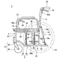
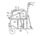
図1及び図2に示された車いす2は、一対のサイドフレーム4、一対の背フレーム6、前後一対のクロスメンバー対8、一対の車輪10、一対のキャスター12、座板14、背傾斜装置16及び座傾斜装置18を備えている。図1の左向きが車いす2の前向きであり、右向きが車いす2の後向きである。図2の左右方向が車いす2の巾方向であり、図2の右向きが車いす2の左向きであり、図2の左向きが車いす2の右向きである。
1 and 2 includes a pair of side frames 4, a pair of back frames 6, a pair of front and
サイドフレーム4は、上側前後杆20、下側前後杆22、前側杆24、後側杆26及び肘掛け杆27を備えている。上側前後杆20は前後方向の延びている。この上側前後杆20には、杆受け20aが形成されている。下側前後杆22は上側前後杆20の下方に位置して、上側前後杆20と平行の延びている。前側杆24は上下方向の延びている。前側杆24に、上側前後杆20の前端と下側前後杆22の前端とが固定されている。後側杆26は、上下方向の延びている。後側杆26に、上側前後杆20の後端と下側前後杆22の後端とが固定されている。肘掛け杆27は、上側前後杆20の上方に上側前後杆20と平行に延びている。肘掛け杆27の前端部は下方に延びて上側前後杆20の前端部に固定されている。肘掛け杆27の後端部は下方に延びて上側前後杆20の後端部に固定されている。上側前後杆20、下側前後杆22、前側杆24、後側杆26及び肘掛け杆27は、例えば金属製の中空パイプからなる。これらの固定は、例えば溶接でされている。
The
背フレーム6は、下方から上方に向かって延びている、背フレーム6は、上方で後方に屈曲して延びている。上方で後方に延びる後端部に、グリップ28が固定されている。このグリップ28は、車いす2を押す補助者に握られる。背フレーム6の下端部は、サイドフレーム4の上側前後杆20に軸着されている。背フレーム6は、サイドフレーム4に対して回動可能にされている。背フレーム6は、左右方向を回動軸として回動可能にされている。
The
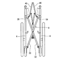
前後一対のクロスメンバー対8は、それぞれ左右一対のサイドフレーム4を連結する連結体を構成している。前後一対のクロスメンバー対8は、それぞれ第一クロスメンバー30及び第二クロスメンバー32を備えている。第一クロスメンバー30は、その上端に上側杆34を備えている。この上側杆34は、前後方向に延びている。第一クロスメンバー30は、その下端に下側杆36を備えている。この下側杆36は、前後方向に延びている。第二クロスメンバー32も、第一クロスメンバー30と同様に、上側杆38及び下側杆40を備えている。
The pair of front and
第一クロスメンバー30と第二クロスメンバー32とは、中央部で軸着されている。第一クロスメンバー30と第二クロスメンバー32とは、互いに回動可能に連結されている。下側杆36は、右のサイドフレーム4の下部に軸着されている。下側杆36の軸線を回動軸にして、第一クロスメンバー30がサイドフレーム4に対して回動可能に連結されている。上側杆34は、左のサイドフレーム4の杆受け20aに着脱可能に支持されている。下側杆40は、下側杆36と同様に、左のサイドフレーム4の下部に軸着されている。上側杆38は、上側杆34と同様に、右のサイドフレーム4の杆受け20aに着脱可能に支持されている。
The
車軸10は、サイドフレーム4の後側杆26に取付されている。車輪10は、サイドフレーム4の左右方向外側に回転可能に取付されている。キャスター12は、車輪42及び車輪支持部44を備えている。車輪支持部44は、車輪42を支持している。車輪42は、水平方向を回転軸にして回転可能にされている。この車輪支持部44は、サイドフレーム4の前側杆24の下部に取り付けられている。車輪支持部44は、上下方向を回転軸にして回転可能に取り付けされている。
The
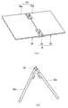
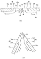
図3(a)及び図4(a)には、座板14が示されている。座板14は、上方に面する座面14aを備えている。座板14は、左座板46、右座板48及び軸50を備えている。左座板46の右縁部と右座板48の左縁部とが軸50により連結されている。左座板46と右座板48とは、前後方向を回動軸として回動可能に連結されている。図4(a)に示される様に、左座板46は、左座板本体52及び左羽板54を備えている。右座板48は、右座板本体56及び右羽板58を備えている。
3A and 4A show the
左座板本体52には上面52aが形成されている。この上面52aは、図3(a)に示される状態で上方に面する平面である。この上面52aは略長方形の平面として形成されている。左座板本体52は、例えば、アクリロニトリル−ブタジエン−スチレン共重合樹脂(ABS樹脂)板などの合成樹脂板で形成されている。左座板本体52は、他の材料からなってもよい。右座板本体56は、軸50の軸線を対称軸として、左座板本体56と左右対称の形状を備えている。左座板本体52と同様に、その上面56aを備えている。右座板本体56も、樹脂板で形成されており、他の材料からなってもよい。
An
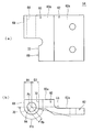
図5(a)及び図5(b)には、左羽板54が示されている。図5(a)の上下方向下向きが左羽板54の前後方向前向きとして、図5(a)の左右方向左向きが左羽板54の左右方向右向きとして、図5(b)の上下方向上向きが左羽板54の上下方向上向きとして、左羽板54の構成について説明される。
The
左羽板54は、連結部60及び取付部62を備えている。連結部60は、取付部62の右側に位置している。連結部60には、軸孔64が形成されている。軸孔64は、連結部60の右縁に形成されて、前後方向に貫通している。連結部60には、切り欠き66が形成されている。切り欠き66は、連結部60の右縁に形成されている。切り欠き66は、軸孔64の前方に形成されている。軸孔64は、切り欠き66に向かって貫通している。
The
連結部60は、その上向きに面する平面60aが形成されている。連結部60の、軸孔64が形成された部分の右側面には、当接面68及び非当接面70とが形成されている。当接面68は、平面60aに直交して下方に延びる平面として形成されている。当接面68の下方に非当接面70が連続して形成されている。切り欠き66には、右向きに対向する当接面72が形成されている。当接面72は、平面60aに直交して下方に延びている。
The connecting
図5の点Pbは、軸孔64の中心を示している。二点鎖線直線Lbは、点Pbを通る直線である。この直線Lbは、平面60aに平行に延びている。両矢印D1は、点Pbから当接面68までの距離を示している。両矢印D2は、点Pbから当接面72までの距離を示している。両矢印Rbは、点Pbから非当接面70までの距離を示している。
A point Pb in FIG. 5 indicates the center of the
当接面68は、この直線Lbと平面60aとの間に形成されている。当接面68は、平面60aと直交する平面である。距離D1は、点Pbと当接面68との最小距離にされている。非当接面70は、直線Lbより下方に形成される。非当接面70は、例えば点Pbを中心とする円弧状の曲面で形成されている。両矢印θbは、この非当接面70が形成される範囲を示している。当接面72も、平面60aと直交する平面である。距離D2は、点Pbと当接面72との最小距離にされている。
The
取付部62は、上方に面する取付面62aが形成されている。この取付面62aは、平面60aと平行に形成された平面である。この取付面62aは、平面60aより、下方に位置している。取付部62には、一対の取付孔が開けられてる。この取付孔は、上下方向に貫通している。右羽板58は、この左羽板54と同一の形状を備えている。右羽板58は、図3(a)の左羽板54と左右逆向きに配置されている。
The mounting
図4(a)に示される様に、左羽板54の取付面62aに座板本体52の下面が重ね合わされる。取付部62の取付孔にねじが通されて、左羽板54は座板本体52にねじ止めされている。この例では、左羽板54の平面60aと左座板本体52の上面52aが同一平面にされている。この平面60aと上面52aとは同一平面でなくともよい。例えば、平面60aが上面52aより下方に位置していもよい。この様にして、左座板46が構成されている。右座板48は、左座板46と同様にして、右座板本体56と右羽板58とが一体にされて構成されている。
As shown in FIG. 4A, the lower surface of the seat plate
図4(a)に示される様に、左羽板54の平面60aと右羽板58の平面60aとが同一平面にされる。左羽板54の当接面72が右羽板58の当接面68に当接させられる。図示されないが、左羽板54の当接面68が右羽板58の当接面72に当接させられる。この左羽板54の軸孔64と右羽板58の軸孔64とに軸50が通される。この様にして左羽板54と右羽板58とが回動可能に連結されている。左座板46と右座板48とが前後方向を回動軸として回動可能に連結されている。
As shown in FIG. 4A, the
図3(a)では、上面52aと上面56aとが同一平面にされている。上面52aと上面56aとが座板14の座面14aを構成している。図示されないが、この座面14aに例えばクッションや座布が敷かれ、使用者が着座する。使用者の臀部が支持される。図3(a)には、座板14の使用状態が示されている。
In FIG. 3A, the
図3(b)では、上面52aと上面56aとが互いに外向きにされて、山折りにされている。図3(b)には、座板14の折り畳み状態が示されている。この座板14は、図3(a)の使用状態と、図3(b)の折り畳み状態との間で、左座板46と右座板48とが回動可能に連結されている。
In FIG.3 (b), the
図1に示されるように、左座板46の前端部は、クロスメンバー対8の上側杆34の前端部に連結されている。左座板46は、上側杆34に左右方向回動軸として回動可能に連結されている。同様に、右座板48の前端部は、クロスメンバー対8の上側杆38の前端部に連結されている。右座板48は、上側杆38に左右方向を回動軸として回動可能に連結されている。図3(a)の使用状態において、座板14は、上側杆34及び上側杆38に対して回動可能に連結されている。座板14は、左右方向を回動軸にして回動可能にされている。
As shown in FIG. 1, the front end portion of the
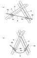
図1及び図2の背傾斜装置16は、伸縮器としてのガススプリング74と、レバー76とを備えている。図1及び図6(a)に示される様に、背傾斜装置16は、レバー76とガススプリング74とに連結されたワイヤー78と、このワイヤー78を覆うレバー側チューブ80a及びガススプリング側チューブ80bとを備えている(図6(a)参照)。
The
図1に示される様に、ガススプリング74のロッド74aの下端部が、サイドフレーム4に回動可能に連結されている。ガススプリング74のシリンダーチューブ74bの上端部が背フレーム6に回動可能に連結されている。ガススプリング74では、ロッド74aの下端部とシリンダーチューブ74bの上端部とが離れる伸張向きに付勢力が作用している。レバー76は、背フレーム6に回動可能に取り付けられている。このレバー76は、グリップ28と共に握られる位置に取り付けられている。このレバー76が握られると、ワイヤー78がレバー76の向きに引かれる。ワイヤー78が引かれると、ガススプリング74の伸縮のロックが解除される。このレバー76は、肘掛け杆27に取り付けられてもよい。
As shown in FIG. 1, the lower end portion of the
図6(a)に示される様に、このワイヤー78を覆うチューブ80は、レバー側チューブ80aと機器側チューブとしてのガススプリング側チューブ80bとに分割されている。このチューブ80aがレバー側開口80cを備えている。開口80cは、第二クロスメンバー32に取り付けられている。チューブ80bが機器側開口80dを備えている。開口80dは、第一クロスメンバー30に取り付けられている。図6(a)に示された使用状態では、開口80cと開口80dとは、離れている。開口80cと開口80dとの間では、ワイヤー78はチューブ80に覆われていない。
As shown in FIG. 6A, the tube 80 covering the
図1及び図2の座傾斜装置18は、伸縮器としてのガススプリング82と、レバー84と、このレバー84とガススプリング82とに連結されたワイヤーと、ワイヤーを覆うレバー側チューブ86a及びガススプリング側チューブ86bと、取付具88と、座板連結具90とを備えている。
1 and 2 includes a
ガススプリング82のロッド82aの下端部が、取付具88に連結されている。この取付具88がクロスメンバー対8に取り付けられている。ガススプリング82のシリンダーチューブ82bの上端部に一対の座板連結具90の一端が連結されている。一方の座板連結具90の他端が左座板46に連結されている。他方の座板連結具90の他端が右座板48に連結されている。ガススプリング82では、ロッド82aの下端部とシリンダーチューブ82bの上端部とが離れる伸張向きに付勢力が作用している。レバー84は、肘掛け杆27に回動可能に取り付けられている。このレバー84が握られると、ワイヤーがレバー84向きに引かれる。ワイヤーが引かれると、ガススプリング82の伸縮のロックが解除される。このレバー84は、背フレーム6に取り付けられてもよい。
The lower end of the
図示されないが、レバー84とガススプリング82とに連結されたワイヤー、チューブ86a及びチューブ86bも、ワイヤー78、チューブ80a及びチューブ80bと同様にして、クロスメンバー対8に取り付けられている。
Although not shown, the wire, the
図7には、リクライニング姿勢の車いす2が示されている。リクライニング姿勢では、背フレーム6の上端部が後側下方に倒されている。グリップ28が後側下方に回動させられている。リクライニング姿勢では、ガススプリング74の長さは、図1の着座姿勢のそれに比べて短くなっている。
FIG. 7 shows the
図1の着座姿勢から図7のリクライニング姿勢への姿勢変化の方法が説明される。図1の着座姿勢にある車いす2において、グリップ28と共に、レバー76が握られる。ワイヤー78が引かれて、ガススプリング74の伸縮のロックが解除される。ガススプリング74の付勢力に抗して、グリップ28が押し下げられる。背フレーム6の上端部が後側下方に回動させられる。背フレーム6が回動して、図7のリクライニング姿勢に至る。レバー76から手が離されると、レバー76は、図示しないスプリングの付勢力で、グリップ28から離れる向きに回動する。ガススプリング74の伸縮がロックされる。背フレーム6が図7のリクライニング姿勢で固定される。
A method of changing the posture from the sitting posture of FIG. 1 to the reclining posture of FIG. 7 will be described. In the
図7のリクライニング姿勢から図1の着座姿勢への姿勢変化の方法が説明される。図7のリクライニング姿勢にある車いす2において、グリップ28と共に、レバー76が握られる。ワイヤー78が引かれて、ガススプリング74の伸縮のロックが解除される。ガススプリング74の付勢力により、背フレーム6の上端部が前側上方に回動させられる。背フレーム6が回動して、図1の着座姿勢に至る。レバー76から手が離されると、レバー76は、図示しないスプリングの付勢力で、グリップ28から離れる向きに回動する。ガススプリング74の伸縮がロックされる。背フレーム6が着座姿勢で固定される。この車いす2では、ガススプリング74の付勢力が背フレーム6の回動を補助する。この車いす2では、使用者の背が背フレーム6に支えられた状態でも、車いす2が容易に着座姿勢に戻される。
A method of changing the posture from the reclining posture of FIG. 7 to the sitting posture of FIG. 1 will be described. In the
図8には、折り畳み状態にされた車いす2が示されている。この折り畳み状態の車いす2では、図1の使用状態の車いす2に対して、一対のサイドフレーム4の間の距離が狭くなっている。第一クロスメンバー30と第二クロスメンバー32とが回動させられている。上側杆34と上側杆38とが上方に位置している。右座板46と左座板48とが上方に位置している。座板14は、図3(b)に示された折り畳み状態にされている。折り畳み状態にされた車いす2は、左右方向の幅が狭くされている。折り畳み状態にされた車いす2は、狭い空間に保管できる。折り畳み状態にされた車いす2は、例えば自動車等での運搬に適している。
FIG. 8 shows the
図6(b)に示される様に、折り畳み状態では、開口80cと開口80dとの距離は、図6(a)の使用状態での距離に比べて狭くなっている。図6(b)では、開口80cと開口80dとの間で、ワイヤー78に弛みが生じている。この折り畳み状態の車いす2では、レバー76が握られてワイヤー78が引かれると、この引き代の分だけ、ワイヤー78の弛みが小さくなる。レバー76が握られても、このワイヤー78のうち、ワイヤーチューブ80bで覆われた部分はレバー76側に引かれない。ガススプリング74の伸縮のロックは、解除されない。
As shown in FIG. 6B, in the folded state, the distance between the
この車いす2では、折り畳み状態では、背フレーム6の回動がロックされている。折り畳み状態でレバー76が握られても、背フレーム6は回動しない。この車いす2では、不意に、背フレーム6が回動することが阻止されている。運搬中に、背フレーム6が回動することが阻止されている。また、折り畳み状態にすることで、この背フレーム6の回動が阻止されるので、背フレーム6の回動をロックする切替レバーの操作が必要とされない。
In the
この車いす2では、チューブ80がチューブ80aとチューブ80bとに分割され、開口80cと開口80dとの間の距離が変化させられることで、折り畳み状態でのガススプリング74の誤動作が防止されている。この車いす2では、簡易な構成で、ガススプリング74の誤動作が防止されている。
In the
この車いす2では、開口80cと開口80dとがクロスメンバー対8に取り付けられたが、この開口80cと開口80dとの間の距離が使用状態と折り畳み状態とで変化すれば、他の部分に取り付けられてもよい。例えば、開口80cと開口80dとは、座板14に取り付けられてもよいし、左右のサイドフレーム4に取り付けられてもよい。
In this
図9には、座板14の座面14aが傾斜した傾斜姿勢の車いす2が示されている。この座面14aの傾斜姿勢では、座面14aが後方から前方に向かって上方から下方向きに傾斜させられている。この傾斜姿勢では、ガススプリング82の長さは、図1の着座姿勢のそれに比べて長くなっている。
FIG. 9 shows the
図1の着座姿勢から図9の傾斜姿勢への姿勢変化の方法が説明される。図1の着座姿勢にある車いす2において、レバー84が握られる。ワイヤーが引かれて、ガススプリング82の伸縮のロックが解除される。ガススプリング82は、座板14を傾斜姿勢になるように付勢する。座板14が、着座した使用者の臀部を押し上げる向きに付勢する。ガススプリング82の付勢力が、車いす2から使用者が立ち上がることを補助する。座板14が回動して、図9の傾斜姿勢に至る。レバー84から手が離されると、レバー84は、図示しないスプリングの付勢力で、元の位置に回動する。ガススプリング82の伸縮がロックされる。座板14が図9の傾斜姿勢で固定される。
A method of changing the posture from the sitting posture of FIG. 1 to the inclined posture of FIG. 9 will be described. In the
図9の傾斜姿勢から図1の着座姿勢への姿勢変化の方法が説明される。傾斜姿勢にある座板14に使用者が臀部を載せる。レバー84が握られる。ワイヤーが引かれて、ガススプリング82の伸縮のロックが解除される。使用者が座板14に体重をかける。ガススプリング82の付勢力に抗して、座板14が押し下げられる。座板14が回動して、図1の着座姿勢に至る。レバー84から手が離されると、レバー84は、図示しないスプリングの付勢力で、元の位置に回動する。ガススプリング82の伸縮がロックされる。座板14が図1の着座姿勢で固定される。
A method of changing the posture from the inclined posture of FIG. 9 to the sitting posture of FIG. 1 will be described. The user places the buttocks on the
この車いす2では、使用者が着座するときも、使用者が立ち上がるときも、座板14が使用者を補助する。この車いす2は、着座と立ち上がりが容易にされている。
In the
この車いす2では、折り畳み状態では、座板14の回動がロックされている。レバー84が握られても、座板14が回動しない。この車いす2では、折り畳み状態で、座板14が回動することが阻止されている。折り畳み状態で、座板14が回動すると、上側杆34及び上側杆38との軸着部分を損傷する恐れがある。折り畳み状態での座板14の回動は、故障の原因にもなり得る。この車いす2は、誤動作による損傷が抑制されている。また、折り畳み状態にすることで座板14の回動が阻止されるので、座板14の回動をロックする切替レバーの操作が必要とされない。
In the
ここでは、背フレーム6の回動の誤動作防止と、座板14の回動の誤動作防止とを例に説明がされたが、これに限られない。一対のサイドフレーム4の間の距離が使用状態と折り畳み状態とで変化する車いす2において、使用状態と折り畳み状態とのいずれか一方の状態で作動する機器の誤動作防止装置として適用しうる。
Here, the prevention of the malfunction of the rotation of the
例えば、開口80cと開口80dとの一方を、クロスメンバー対8の上側杆34側に取り付け、他方を下側杆40側にを取り付けてもよい。これにより、開口80cと開口80dとの距離は、使用状態が折り畳み状態より狭くなる。これにより、折り畳み状態で作動する機器の、使用状態での誤動作を防止しうる。この使用状態での開口80cと開口80dとの距離が折り畳み状態のそれより狭くなることも、本発明の一対のサイドフレーム4の間隔の変化に基づいくものである。本発明は、この開口80cと開口80dとの間の距離が使用状態と折り畳み状態とで変化する車いす2の誤動作防止装置として広く適用しうる。
For example, one of the
ここでは、開口80cと開口80dとの間で弛むワイヤーを例に説明がされたが、この例に限られない。車いす2の使用状態と折り畳み状態との、一対のサイドフレーム4の間隔の変化に基づいて、使用状態と折り畳み状態との一方の状態で、機器が作動可能とされ、他方の状態で機器の作動が規制されればよい。例えば、機器の作動を機械的に規制するストッパーを備え、このストッパーが他方の状態で機器の作動を機械的に規制する位置に設けられてもよい。また、機器の作動の許容と規制とに切り替えるレバーを備え、このレバーが他方の状態で機器の作動を規制する向きに回動し、一方の状態で機器の作動を許容する向きに回動する位置に設けられてよい。
Here, the wire that is slackened between the
この車いす2では、使用状態と折り畳み状態に対応して、座板14は図3(a)の使用状態と図3(b)の折り畳み状態との間で、左座板46と右座板48とが回動可能にされている。図3(b)の折り畳み状態では、上面52aと上面56aとが互いに外向きにされて、山折りにされている。
In the
図4(a)に示される様に、座板14の使用状態では、左座板46の当接面72が右座板48の当接面68と当接している。図示されないが、同様に、左座板46の当接面68が右座板48の当接面72と当接している。これにより、図3(a)の使用状態から、更に、上面52aと上面56aとが互いに内向きに回動することが阻止されている。当接面68と当接面72との当接により、使用状態において座板14の座面14aは一平面にされている。当接面68と当接面72とが左座板46と右座板48との対向する側面に形成されているので、使用状態において座板14の座面上に突出する突起部が生じない。この座板14は、使用状態において、着座する使用者に違和感を与えない。
As shown in FIG. 4A, when the
また、直線Lbを境界にして、その上方に当接面68が形成され、その下方に非当接面70が形成されている。この直線Lbより下方の側面が非当接面70にされているので、図4(b)に示される様に、左座板46と右座板48とが回動して折り畳み状態になりうる。この座板14は、図3(a)の使用状態と、図3(b)の折り畳み状態との間で、左座板46と右座板48とが回動可能に連結されている。
Further, a
図5(b)に示された角度θbを大きくすることで、左座板46と右座板48とが回動可能角度を大きくすることが出来る。この観点から角度θbは好ましくは90°以上であり、更に好ましくは115°以上であり、特に好ましくは135°以上である。一方で、角度θbを小さくすることで、強度を大きく出来る。この観点から、角度θbは好ましくは170°以下であり、更に好ましくは160°以下であり、特に好ましくは150°以上である。
By increasing the angle θb shown in FIG. 5B, the angle at which the
この座板14では、左羽板54と右羽板58とが金属製にされることが好ましい。これにより、当接面68及び当接面72の摩耗や損傷が抑制されている。この車いす2は、耐久性に優れている。一方で、左座板本体52と右座板本体56とが合成樹脂板にされているので、軽量化されている。この車いす2は、耐久性に優れ、且つ軽量化されている。更に、左羽板54と右羽板58とが合成樹脂製にされて、当接面68及び当接面72が金属板で形成され、軸孔64が金属製ブシュ(滑り軸受け)で形成されてもよい。
In the
以上説明された構成は、折り畳み車いすに広く適用されうる。 The configuration described above can be widely applied to folding wheelchairs.
2・・・車いす
4・・・サイドフレーム
6・・・背フレーム
8・・・クロスメンバー対
14・・・座板
16・・・背傾斜装置
18・・・座傾斜装置
30・・・第一クロスメンバー
32・・・第二クロスメンバー
34、38・・・上側杆
36、40・・・下側杆
46・・・左座板
48・・・右座板
50・・・軸
52・・・左座板本体
54・・・左羽板
56・・・右座板本体
58・・・右羽板
68・・・当接面
70・・・非当接面
72・・・当接面
74、82・・・ガススプリング
76、84・・・レバー
78・・・ワイヤー
80、86・・・チューブ
80a、86a・・・レバー側チューブ
80b、86b・・・ガススプリング側チューブ
80c、86c・・・レバー側開口
80d、86d・・・機器側開口
DESCRIPTION OF
Claims (4)
この使用状態と折り畳み状態との左右一対のサイドフレームの間隔の変化に基づいて、使用状態と折り畳み状態との一方の状態でこの機器が作動可能とされ、他方の状態でこの機器の作動が規制されており、
ワイヤーと、このワイヤーを引くレバーとを備えており、
上記機器がこのワイヤーが引かれることで操作されており、
上記使用状態と折り畳み状態との一方の状態でワイヤーが張られ、この機器が作動可能とされており、他方の状態でワイヤーに弛みを生じさせて、この機器の作動が規制されており、
上記ワイヤーを覆うチューブを備えており、
このチューブがワイヤーのレバー側を覆うレバー側チューブとワイヤーの機器側を覆う機器側チューブとに分割されており、
このレバー側チューブがレバー側開口を備えており、機器側チューブが機器側開口を備えており、このレバー側開口と機器側開口との間の距離が使用状態と折り畳み状態とで変化しており、
このレバー側開口と機器側開口との間の距離が小さくなったときに、レバー側開口と機器側開口との間でワイヤーが弛んでおり、上記レバーが引かれるとこの引き代の分だけ上記ワイヤーの緩みが小さくなる車いす。 A pair of left and right side frames and a pair of left and right side frames are connected so that the distance between them can be seated, and a folded state in which the distance between the pair of left and right side frames is closer than the state of use. And a device that operates in either one of a use state and a folded state,
Based on the change in the distance between the pair of left and right side frames between the use state and the folded state, the device is operable in one state of the use state and the folded state, and the operation of the device is regulated in the other state. Has been
It has a wire and a lever that pulls this wire,
The above equipment is operated by pulling this wire,
The wire is stretched in one state of the use state and the folded state, the device is operable, the wire is slackened in the other state, and the operation of the device is regulated,
A tube covering the wire,
This tube is divided into a lever side tube that covers the lever side of the wire and a device side tube that covers the device side of the wire,
The lever side tube has a lever side opening, the device side tube has a device side opening, and the distance between the lever side opening and the device side opening varies between the use state and the folded state. ,
When the distance between the lever side opening and the device side opening becomes small, the wire is loosened between the lever side opening and the device side opening. A wheelchair with less wire loosening .
この背フレームが上記サイドフレームに対して回動可能にされており、
この背フレームが、その上端部が上方に起こされた着座姿勢と上端部が後側下方に倒されたリクライニング姿勢との間で回動可能にされており、
上記機器が、背フレームの上端部を下方から上方に回動する向きに、背フレームを付勢する伸縮器である請求項1に記載の車いす。 It has a back frame,
The back frame is rotatable with respect to the side frame,
The back frame is configured to be rotatable between a sitting posture in which the upper end portion is raised upward and a reclining posture in which the upper end portion is tilted downward on the rear side,
The wheelchair according to claim 1, wherein the device is a telescopic device that urges the back frame in a direction in which the upper end of the back frame is rotated upward from below.
この座板が着座姿勢と座板の前端部に対して後端部が上方に回動する傾斜姿勢との間で回動可能にされており、
上記機器が、座板の後端部が下方から上方に回動する向きに、座板を付勢する伸縮器である請求項1に記載の車いす。 It has a seat plate,
The seat plate is rotatable between a sitting posture and an inclined posture in which the rear end portion rotates upward with respect to the front end portion of the seat plate,
The wheelchair according to claim 1, wherein the device is a telescopic device that urges the seat plate in a direction in which the rear end portion of the seat plate rotates upward from below.
この左座板の上面と右座板の上面とが一平面にされた使用状態と、左座板の上面と右座板の上面とが互いに外向きにされた折り畳み状態との間で、左座板と右座板とが回動可能に連結されており、
左座板と右座板との少なくとも一方に回動可能に軸を支持する軸孔が形成されており、
この軸孔が形成された側面に使用状態で他方の側面に当接する当接面と他方に当接しない非当接面とが形成されており
この軸孔の中心Pbを通って上面に平行な直線を直線Lbとすると、この当接面が上面と直線Lbとの間に形成されており、
この直線Lbより上面から離れた下方の側面が非当接面にされている請求項1から3のいずれかに記載の車いす。 A seat plate that forms a seat surface, the seat plate includes a left seat plate and a right seat plate, and the upper surface of the left seat plate and the upper surface of the right seat plate are in a single plane; The left seat plate and the right seat plate are rotatably connected between the folded state in which the upper surface of the left seat plate and the upper surface of the right seat plate face each other outwardly,
A shaft hole that rotatably supports the shaft is formed in at least one of the left seat plate and the right seat plate,
A contact surface that contacts the other side surface and a non-contact surface that does not contact the other side surface are formed on the side surface where the shaft hole is formed, and is parallel to the upper surface through the center Pb of the shaft hole. If the straight line is a straight line Lb, this contact surface is formed between the upper surface and the straight line Lb,
The wheelchair according to any one of claims 1 to 3, wherein a lower side surface farther from the upper surface than the straight line Lb is a non-contact surface.
Priority Applications (1)
| Application Number | Priority Date | Filing Date | Title |
|---|---|---|---|
| JP2013190242A JP6261069B2 (en) | 2013-09-13 | 2013-09-13 | wheelchair |
Applications Claiming Priority (1)
| Application Number | Priority Date | Filing Date | Title |
|---|---|---|---|
| JP2013190242A JP6261069B2 (en) | 2013-09-13 | 2013-09-13 | wheelchair |
Publications (2)
| Publication Number | Publication Date |
|---|---|
| JP2015054169A JP2015054169A (en) | 2015-03-23 |
| JP6261069B2 true JP6261069B2 (en) | 2018-01-17 |
Family
ID=52818977
Family Applications (1)
| Application Number | Title | Priority Date | Filing Date |
|---|---|---|---|
| JP2013190242A Active JP6261069B2 (en) | 2013-09-13 | 2013-09-13 | wheelchair |
Country Status (1)
| Country | Link |
|---|---|
| JP (1) | JP6261069B2 (en) |
Families Citing this family (1)
| Publication number | Priority date | Publication date | Assignee | Title |
|---|---|---|---|---|
| CN109157346B (en) * | 2018-10-10 | 2024-02-27 | 安维车件(厦门)有限公司 | Wire lifting device and wheelchair using same |
Family Cites Families (4)
| Publication number | Priority date | Publication date | Assignee | Title |
|---|---|---|---|---|
| KR20080013858A (en) * | 2005-05-18 | 2008-02-13 | 료비 가부시키가이샤 | Seat lift wheelchairs, brake devices for seat lift wheelchairs, and suspension devices for seat lift actuators |
| JP4943093B2 (en) * | 2006-08-29 | 2012-05-30 | 株式会社カワムラサイクル | Folding wheelchair |
| JP5093888B2 (en) * | 2007-11-13 | 2012-12-12 | 株式会社いうら | Bathing assistance wheelchair |
| JP2010268915A (en) * | 2009-05-20 | 2010-12-02 | Michiko Oshima | Wheelchair seat plate |
-
2013
- 2013-09-13 JP JP2013190242A patent/JP6261069B2/en active Active
Also Published As
| Publication number | Publication date |
|---|---|
| JP2015054169A (en) | 2015-03-23 |
Similar Documents
| Publication | Publication Date | Title |
|---|---|---|
| US8740243B2 (en) | Foldable stroller frame | |
| CN107468438B (en) | Folding electric wheelchair | |
| JP6630859B2 (en) | Strollers and front guard members | |
| JP6654460B2 (en) | stroller | |
| JP6261069B2 (en) | wheelchair | |
| JP5325743B2 (en) | Walking assistance vehicle | |
| JP5744572B2 (en) | wheelchair | |
| JP6144270B2 (en) | baby carriage | |
| US6644733B1 (en) | Chair with a seat slidable relative to a seat base for synchronously actuating a footrest and a backrest | |
| CA2876578A1 (en) | Footrest for construction machine operating room | |
| JP2001149413A (en) | Wheelchair | |
| JP5052372B2 (en) | Wheelchair with transfer assistance function | |
| JP6631790B2 (en) | Double wheel vehicle | |
| JP5067806B2 (en) | Reclining wheelchair | |
| JP4422169B2 (en) | Wheelchair walker | |
| JP3888661B2 (en) | Portable wheelchair | |
| JP3831824B2 (en) | Retractable grip | |
| JP3124218U (en) | Walker | |
| KR101244451B1 (en) | Brake system for wheelchair | |
| JP2005118144A (en) | Folding wheelchair | |
| JP4943093B2 (en) | Folding wheelchair | |
| JP3622069B2 (en) | Wheelchair frame | |
| KR101244450B1 (en) | Brake system for wheelchair | |
| GB2480724A (en) | A stroller with a head protecting structure | |
| JP3955984B2 (en) | Reclining wheelchair |
Legal Events
| Date | Code | Title | Description |
|---|---|---|---|
| A621 | Written request for application examination |
Free format text: JAPANESE INTERMEDIATE CODE: A621 Effective date: 20160519 |
|
| A131 | Notification of reasons for refusal |
Free format text: JAPANESE INTERMEDIATE CODE: A131 Effective date: 20170502 |
|
| A521 | Request for written amendment filed |
Free format text: JAPANESE INTERMEDIATE CODE: A523 Effective date: 20170630 |
|
| TRDD | Decision of grant or rejection written | ||
| A01 | Written decision to grant a patent or to grant a registration (utility model) |
Free format text: JAPANESE INTERMEDIATE CODE: A01 Effective date: 20171128 |
|
| RD02 | Notification of acceptance of power of attorney |
Free format text: JAPANESE INTERMEDIATE CODE: A7422 Effective date: 20171208 |
|
| A61 | First payment of annual fees (during grant procedure) |
Free format text: JAPANESE INTERMEDIATE CODE: A61 Effective date: 20171208 |
|
| R150 | Certificate of patent or registration of utility model |
Ref document number: 6261069 Country of ref document: JP Free format text: JAPANESE INTERMEDIATE CODE: R150 |
|
| R250 | Receipt of annual fees |
Free format text: JAPANESE INTERMEDIATE CODE: R250 |
|
| R250 | Receipt of annual fees |
Free format text: JAPANESE INTERMEDIATE CODE: R250 |
|
| R250 | Receipt of annual fees |
Free format text: JAPANESE INTERMEDIATE CODE: R250 |
|
| R250 | Receipt of annual fees |
Free format text: JAPANESE INTERMEDIATE CODE: R250 |
|
| R250 | Receipt of annual fees |
Free format text: JAPANESE INTERMEDIATE CODE: R250 |
|
| R250 | Receipt of annual fees |
Free format text: JAPANESE INTERMEDIATE CODE: R250 |