JP6260359B2 - Data division processing program, data division processing device, and data division processing method - Google Patents
Data division processing program, data division processing device, and data division processing method Download PDFInfo
- Publication number
- JP6260359B2 JP6260359B2 JP2014045042A JP2014045042A JP6260359B2 JP 6260359 B2 JP6260359 B2 JP 6260359B2 JP 2014045042 A JP2014045042 A JP 2014045042A JP 2014045042 A JP2014045042 A JP 2014045042A JP 6260359 B2 JP6260359 B2 JP 6260359B2
- Authority
- JP
- Japan
- Prior art keywords
- data
- binary data
- file
- record
- detected
- Prior art date
- Legal status (The legal status is an assumption and is not a legal conclusion. Google has not performed a legal analysis and makes no representation as to the accuracy of the status listed.)
- Active
Links
Images


Classifications
-
- G—PHYSICS
- G06—COMPUTING; CALCULATING OR COUNTING
- G06F—ELECTRIC DIGITAL DATA PROCESSING
- G06F16/00—Information retrieval; Database structures therefor; File system structures therefor
- G06F16/10—File systems; File servers
- G06F16/18—File system types
- G06F16/182—Distributed file systems
-
- G—PHYSICS
- G06—COMPUTING; CALCULATING OR COUNTING
- G06F—ELECTRIC DIGITAL DATA PROCESSING
- G06F16/00—Information retrieval; Database structures therefor; File system structures therefor
- G06F16/90—Details of database functions independent of the retrieved data types
- G06F16/95—Retrieval from the web
- G06F16/955—Retrieval from the web using information identifiers, e.g. uniform resource locators [URL]
- G06F16/9566—URL specific, e.g. using aliases, detecting broken or misspelled links
-
- G—PHYSICS
- G06—COMPUTING; CALCULATING OR COUNTING
- G06F—ELECTRIC DIGITAL DATA PROCESSING
- G06F16/00—Information retrieval; Database structures therefor; File system structures therefor
- G06F16/90—Details of database functions independent of the retrieved data types
- G06F16/95—Retrieval from the web
- G06F16/957—Browsing optimisation, e.g. caching or content distillation
- G06F16/9574—Browsing optimisation, e.g. caching or content distillation of access to content, e.g. by caching
Description
本発明は、データ分割処理プログラム,データ分割処理装置及びデータ分割処理方法に関する。 The present invention relates to a data division processing program, a data division processing device, and a data division processing method.
近年、ウェブデータ等の大量のデータを処理するための処理システムとして、マップ−リデュース(Map-Reduce)型の分散処理システムが知られている。
マップ−リデュース型の分散処理システムにおいては、分散処理システム上のデータをデータブロックと呼ばれる単位に分割し、これらのデータブロックに対してマップ処理及びリデュース処理を順次適用する。
In recent years, a map-reduce distributed processing system is known as a processing system for processing a large amount of data such as web data.
In a map-reduce type distributed processing system, data on the distributed processing system is divided into units called data blocks, and map processing and reduction processing are sequentially applied to these data blocks.
このようなマップ−リデュース型の分散処理システムによれば、各データブロックに対する一連の計算処理を複数の計算ノードで同時に分散して実行することが可能となる。
Hadoop(登録商標)は大規模データを効率的に分散処理・管理するためのOSS(Open Source Software)のフレームワークであり、主に分析処理で活用されている。このHadoopを基幹系のバッチ処理に適用することにより、データを複数のマシンに分散して処理させ、処理時間が課題となっている大規模バッチ処理の高速化が実現できる。
According to such a map-reduce type distributed processing system, a series of calculation processing for each data block can be simultaneously distributed and executed by a plurality of calculation nodes.
Hadoop (registered trademark) is an OSS (Open Source Software) framework for efficiently distributing and managing large-scale data, and is mainly used in analysis processing. By applying this Hadoop to core batch processing, data can be distributed and processed across multiple machines, and high-speed batch processing, where processing time is an issue, can be realized.
Hadoopにおいては、マスタノードが複数のスレーブノードにタスクをそれぞれ割り当て、スレーブノードは、マスタノードから割り当てられたマップタスク(Mapタスク)を実行する。
Hadoopでは、ファイルを一定のサイズのブロックに分割し、そのブロック毎にマップタスクで処理を行う。
In Hadoop, a master node assigns tasks to a plurality of slave nodes, and the slave node executes a map task (Map task) assigned from the master node.
In Hadoop, a file is divided into blocks of a certain size, and each block is processed by a map task.
図15はHadoopのマップ−リデュースフレームワークの動作概要を示す図である。図15に示す例においては、Hadoop分散ファイルシステム(HDFS:Hadoop Distributed File System)によって管理される196MBのファイルが64MBのデータサイズを有する3つのブロックに分割され、それらを3つのマップタスクで並列に処理している。マップタスクから出力されたデータは、Shuffle&sortやReduceタスクを経て、ソートされた結果ファイルとして出力され、HDFSに戻される。 FIG. 15 is a diagram showing an outline of the operation of the Hadoop map-reduce framework. In the example shown in FIG. 15, a 196 MB file managed by the Hadoop Distributed File System (HDFS) is divided into three blocks having a data size of 64 MB, and these are divided into three map tasks in parallel. Processing. The data output from the map task is output as a sorted result file through the Shuffle & sort and Reduce tasks, and returned to HDFS.
このような分散処理システムにおいて、ファイルが分割されてもデータ自体は分割されないことが重要である。例えるならば、マップタスクに渡される「みかん」というデータが、「みか」と「ん」に分かれてはならない。このように一体として扱われるべきデータが分割されてしまうことを泣き別れという場合がある。
このため、64MBでファイル分割が行なわれた後、データの区切り位置を調整する必要がある。Hadoopのデフォルトでは、データの区切りとして改行コードを用い、この改行コードの位置を区切りとして処理することで、データの泣き別れを防いでいる。この区切りの調整処理はカスタマイズ可能であり、例えば任意の文字を区切りとするような、カスタマイズが可能になっている。
In such a distributed processing system, it is important that the data itself is not divided even if the file is divided. For example, the “Mikan” data passed to the map task should not be divided into “Mika” and “N”. In this way, the division of data that should be handled as a unit may be called crying.
For this reason, it is necessary to adjust the data delimiter position after file division is performed at 64 MB. By default, Hadoop uses a line feed code as a data delimiter, and the position of the line feed code is processed as a delimiter to prevent data from crying. This delimitation adjustment process can be customized. For example, it is possible to customize such that an arbitrary character is used as a delimiter.
図16はNetCOBOLの可変長レコード順ファイルのフォーマットを例示する図である。
NetCOBOLの可変長レコード順ファイルは、この図16に示すように、データの前後に4バイトのレコード長情報を有する可変長レコードを複数連続することにより構成されている。データは利用者が設定する任意のバイナリ値である。また、データの前後に配置されるレコード長には同一の値が格納される。
FIG. 16 is a diagram illustrating the format of a NetCOBOL variable-length record sequential file.
As shown in FIG. 16, the NetCOBOL variable-length record sequential file is composed of a plurality of continuous variable-length records having 4-byte record length information before and after the data. The data is an arbitrary binary value set by the user. The same value is stored in the record lengths arranged before and after the data.
なお、利用者はレコード長情報を設定・参照する必要はなく、COBOLランタイムシステムが参照・設定を行なう。
図17はNetCOBOLの可変長レコード順ファイルのレコードイメージを示す図である。
この図17に示す例においては、1つの可変長レコード毎に改行して見やすくしているが、実際は複数の可変長レコードが連続している。
Note that the user does not need to set or reference the record length information, but the COBOL runtime system refers to and sets it.
FIG. 17 is a diagram showing a record image of a NetCOBOL variable-length record sequential file.
In the example shown in FIG. 17, line feeds are provided for each variable-length record for easy viewing, but actually a plurality of variable-length records are continuous.
NetCOBOLの可変長レコード順ファイルをHadoopで利用する場合、ブロック単位でファイル分割が行われた後、データの区切りを調整することができない。これは、データが利用者が任意に設定可能なバイナリ値であり、改行コードや任意の文字を区切りとする場合に、データ内にこれらの改行コードや区切り文字と同じ情報が含まれるおそれがあり、データの区切り位置を特定できないためである。 When using NetCOBOL variable-length record sequential file with Hadoop, the data delimiter cannot be adjusted after the file is divided into blocks. This is a binary value that can be arbitrarily set by the user. If a line feed code or any character is used as a delimiter, the data may contain the same information as the line feed code or delimiter. This is because the data delimiter position cannot be specified.
図18はNetCOBOLの可変長レコード順ファイルを2つに分割する場合のレコードイメージを示す図である。
この図18に示す例においては、ファイルを64MBのブロックサイズ単位で分割する場合に、データ長が105バイトのデータが、その途中で分断されてしまうことを示す。
そこで、NetCOBOLでは、レコードの位置を正しく求めてデータ区切り位置を調整するために、ブロックサイズによる分断位置から次の可変長レコードの先頭位置までの距離(バイト長)を保持する情報ファイルを予め作成し、この情報ファイルを区切りの調整処理で参照する手法が用いられる。
FIG. 18 is a diagram showing a record image when a NetCOBOL variable-length record sequential file is divided into two.
In the example shown in FIG. 18, when a file is divided in block size units of 64 MB, data having a data length of 105 bytes is divided in the middle.
Therefore, in NetCOBOL, in order to correctly determine the position of the record and adjust the data delimiter position, an information file that holds the distance (byte length) from the division position by the block size to the start position of the next variable-length record is created in advance. Then, a method of referring to this information file in the delimiter adjustment process is used.
図19はNetCOBOLの可変長レコード順ファイルと情報ファイルとを示す図である。
情報ファイルは、入力ファイルである可変長レコード順ファイルを読み込んでレコード長を加算し、ブロックサイズで分断される位置から次のレコード先頭位置までの情報を保持する。
図19に示す例においては、情報ファイルにおいて、例えばファイルを先頭から64MBの位置で分割する場合に、その分断位置から次の可変長レコード(データ長が20バイト)の先頭までのデータ長が55バイトであることを示す。なお、情報サイズ作成時には、ブロックサイズもパラメータで指定する必要がある。
FIG. 19 shows NetCOBOL variable-length record sequential files and information files.
The information file reads a variable-length record sequential file as an input file, adds the record length, and holds information from the position divided by the block size to the next record start position.
In the example shown in FIG. 19, in the information file, for example, when the file is divided at the 64 MB position from the beginning, the data length from the division position to the beginning of the next variable length record (data length is 20 bytes) is 55. Indicates a byte. When creating the information size, it is necessary to specify the block size as a parameter.
しかしながら、このような従来の分散処理システムにおいては、上述した情報ファイルを作成するために、処理対象ファイル全体を、その先頭から可変長レコードのレコード長を順次取り出して加算することで区切り位置を求める。このため、例えば、データサイズが数十〜数百GBであり、レコード件数が数百万件程度の大きなサイズのファイルでは、情報ファイルの作成処理に時間がかかってしまう。例えば80GBのデータサイズのファイルにおいては、情報ファイルの作成に例えば15分程度の時間を要する場合もある。 However, in such a conventional distributed processing system, in order to create the above-described information file, the delimiter position is obtained by sequentially extracting and adding the record lengths of variable-length records from the beginning of the entire processing target file. . For this reason, for example, in the case of a large file having a data size of several tens to several hundred GB and a record number of about several million, it takes time to create an information file. For example, in the case of a file having a data size of 80 GB, it may take about 15 minutes to create an information file.
これにより、本来は処理時間の高速化を目的としてHadoopを導入するにもかかわらず、情報ファイルの作成に時間を要し、全体の処理時間で考えるとHadoopによる時間短縮効果が薄れてしまうという課題がある。
1つの側面では、本発明は、分割処理を高速化できるようにすることを目的とする。
なお、前記目的に限らず、後述する発明を実施するための形態に示す各構成により導かれる作用効果であって、従来の技術によっては得られない作用効果を奏することも本発明の他の目的の1つとして位置付けることができる。
As a result, despite the fact that Hadoop was originally introduced for the purpose of speeding up the processing time, it took time to create an information file, and the time saving effect of Hadoop would be diminished when considered in terms of the overall processing time There is.
In one aspect, an object of the present invention is to enable a high-speed division process.
In addition, the present invention is not limited to the above-described object, and other effects of the present invention can be achieved by the functions and effects derived from the respective configurations shown in the embodiments for carrying out the invention which will be described later. It can be positioned as one of
このため、このデータ分割処理方法は、バイナリデータを複数に分割して複数の処理部
により処理する分割処理方法であって、前記複数の処理部のそれぞれに、前記バイナリデータの一部である部分バイナリデータをそれぞれ割り当て、前記複数の処理部はそれぞれ、割り当てられた部分バイナリデータのデータ区切り位置を、前記バイナリデータを構成
する所定のデータの特性に基づき検出するとともに、検出したデータ区切り位置を示す情
報を記憶手段に登録し、前記複数の処理部はそれぞれ、他の処理部により前記記憶手段に
登録されたデータ区切り位置を示す情報に基づき、前記部分バイナリデータにおいて検出
したデータ区切り位置が正当であるかを判定し、前記処理対象の部分バイナリデータについて検出したデータ区切り位置と、前記記憶手段に登録された、前記バイナリデータにおいて前記処理対象の部分バイナリデータと隣接する部分バイナリデータについてのデータ区切り位置とが連続する場合に、検出したデータ区切り位置が正当であると判断する。
For this reason, this data division processing method is a division processing method in which binary data is divided into a plurality of parts and processed by a plurality of processing units, and each of the plurality of processing units is a part of the binary data. Each of the plurality of processing units detects a data delimiter position of the allocated partial binary data based on characteristics of predetermined data constituting the binary data, and indicates the detected data delimiter position. The information is registered in the storage unit, and each of the plurality of processing units has a valid data delimiter position detected in the partial binary data based on the information indicating the data delimiter position registered in the storage unit by another processing unit. It determines whether the data delimiter position detected for the partial binary data of the processing target , Registered in the storage means, when the partial binary data of the processing target in the binary data and the data delimiter position of adjacent partial binary data consecutive detected data delimiter position is determined to be legitimate .
一実施形態によれば、分割処理を高速化することができる。 According to one embodiment, the division process can be speeded up.
以下、図面を参照して本データ分割処理プログラム,データ分割処理装置及びデータ分割処理方法に係る実施の形態を説明する。ただし、以下に示す実施形態はあくまでも例示に過ぎず、実施形態で明示しない種々の変形例や技術の適用を排除する意図はない。すなわち、本実施形態を、その趣旨を逸脱しない範囲で種々変形して実施することができる。又、各図は、図中に示す構成要素のみを備えるという趣旨ではなく、他の機能等を含むことができる。 Hereinafter, embodiments according to the data division processing program, the data division processing device, and the data division processing method will be described with reference to the drawings. However, the embodiment described below is merely an example, and there is no intention to exclude application of various modifications and techniques not explicitly described in the embodiment. That is, the present embodiment can be implemented with various modifications without departing from the spirit of the present embodiment. Each figure is not intended to include only the components shown in the figure, and may include other functions.
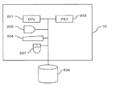
図1は実施形態の一例としての分散処理システム1の機能構成を模式的に示す図、図2はそのサーバのハードウェア構成を例示する図である。
本分散処理システム1は、複数(図1に示す例では4つ)のサーバ(計算ノード,ノード)10−1〜10−4をそなえ、これらの複数のサーバ10−1〜10−4で分散して処理を行なう。本分散処理システム1は、例えばHadoop(登録商標)を用いて分散処理を実現するマップ−リデュースシステムである。Hadoopはデータ(ファイル)を複数のマシンに分散して処理させるオープンソースのプラットフォームであり、公知の技術であるので、その詳細な説明は省略する。
FIG. 1 is a diagram schematically illustrating a functional configuration of a distributed
The distributed
また、本実施形態においては、処理対象のファイルが、図16,図17等に例示したNetCOBOLの規格に沿った可変長レコードファイル(以下、単にファイルという)である例について説明する。すなわち、処理対象のファイルはバイナリデータであり、また、処理対象のファイルは、複数の可変長レコード(単位レコード)を連続することにより構成されている。さらに、個々の可変長レコードにおいては、データの前後に当該データのデータ長を示すレコード長情報が配置されているというデータ構造上の特性(規則性)を有する。なお、可変長レコードにおけるデータよりも前側のレコード長情報を前側レコード長情報といい、データよりも後側に位置するレコード長情報を、後側レコード長情報という場合がある。 In the present embodiment, an example in which the file to be processed is a variable-length record file (hereinafter simply referred to as a file) conforming to the NetCOBOL standard exemplified in FIGS. That is, the file to be processed is binary data, and the file to be processed is configured by continuing a plurality of variable length records (unit records). Furthermore, each variable-length record has a characteristic (regularity) on the data structure that record length information indicating the data length of the data is arranged before and after the data. Note that the record length information ahead of the data in the variable length record may be referred to as front record length information, and the record length information located behind the data may be referred to as rear record length information.
各サーバ10−1〜10−4はネットワーク50を介して相互に通信可能に接続されている。ネットワーク50は、例えばLAN(Local Area Network)等の通信回線である。
サーバ10−1〜10−4は、それぞれサーバ機能をそなえたコンピュータ(情報処理装置,処理部)である。各サーバ10−1〜10−4は、同様の構成を備える。以下、サーバを示す符号としては、複数のサーバのうち1つを特定する必要があるときには符号10−1〜10−4を用いるが、任意のサーバを指すときには符号10を用いる。
The servers 10-1 to 10-4 are connected to each other via the
The servers 10-1 to 10-4 are computers (information processing apparatuses and processing units) each having a server function. Each server 10-1 to 10-4 has the same configuration. Hereinafter, the reference numerals 10-1 to 10-4 are used when it is necessary to specify one of a plurality of servers, but the
また、図1に示す例においては、サーバ10−1がマスタノードとして機能し、サーバ10−2〜10−4がスレーブノードとして機能する。以下、サーバ10−1をマスタノードMNという場合があり、サーバ10−2〜10−4をそれぞれスレーブノードSNという場合がある。
マスタノードMNは、本分散処理システム1における処理を管理する装置であり、複数のスレーブノードSNにタスクをそれぞれ割り当てる。スレーブノードSNは、マスタノードMNから割り当てられたマップタスク(Mapタスク;以下、単にタスクという)を実行する。タスクを分散して割り当てられた複数のスレーブノードSNが、それぞれ割り当てられたタスクを並行して実行することによりジョブの処理時間を短縮する。
In the example illustrated in FIG. 1, the server 10-1 functions as a master node, and the servers 10-2 to 10-4 function as slave nodes. Hereinafter, the server 10-1 may be referred to as a master node MN, and the servers 10-2 to 10-4 may be referred to as slave nodes SN.
The master node MN is a device that manages processing in the distributed
なお、図1に示す例においては、マスタノードMNもタスクトラッカ13(後述)としての機能を備えており、このマスタノードMNにおいても割り当てられたタスクの実行を行なう機能を備えている。従って、図1に例示する分散処理システム1においては、サーバ10−1もスレーブノードSNとして機能する。
また、本実施形態においては、各スレーブノードSNが、それぞれマップタスクを実行するものとする。
In the example shown in FIG. 1, the master node MN also has a function as a task tracker 13 (described later), and the master node MN also has a function of executing the assigned task. Therefore, in the distributed
In the present embodiment, each slave node SN executes a map task.
サーバ10は、例えばサーバ機能をそなえたコンピュータ(情報処理装置,データ分割装置,処理部)である。サーバ10は、図2に示すように、CPU(Central Processing Unit)201,メモリ202,表示装置205,キーボード206,マウス207及び記憶装置208を備える。
メモリ202はROM(Read Only Memory)及びRAM(Random Access Memory)を含む記憶装置である。メモリ202のROMには、分散処理制御に係るソフトウェアプログラムやこのプログラム用のデータ類が書き込まれている。メモリ202上のソフトウェアプログラムは、CPU201に適宜読み込まれて実行される。また、このメモリ202のRAMには、後述するノード間共有情報15が格納される。
The
The
また、メモリ202のRAMは、一次記憶メモリあるいはワーキングメモリとして利用される。さらに、メモリ202のRAMは、分割するファイルを格納する図示しないバッファ領域としても機能する。
表示装置205は、例えば、液晶ディスプレイやCRT(Cathode Ray Tube)ディスプレイであり、種々の情報を表示する。
The RAM of the
The
キーボード206及びマウス207は入力装置であり、利用者がこれらの入力装置を用いて、種々の入力操作を行なう。例えば、マスタノードMNにおいて、利用者は、これらのキーボード206やマウス207を用いて、例えば、処理対象のファイルの指定や処理内容の指定(入力)を行なう。
記憶装置208は種々のデータやプログラムを格納する記憶装置であって、例えば、HDD(Hard Disk Drive)やSSD(Solid State Drive)である。又、記憶装置208は、例えば、複数のHDDを組み合わせて、冗長化された1つのストレージとして管理するRAID(Redundant Arrays of Inexpensive Disks)装置であってもよい。
A
The
CPU201は、種々の制御や演算を行なう処理装置であり、メモリ202に格納されたプログラムを実行することにより、種々の機能を実現する。
マスタノードMNにおいて、CPU201は、図1に示す、ユーザアプリケーション機能部11,ファイル管理部12,ジョブトラッカ14及びタスクトラッカ13として機能する。
The
In the master node MN, the
なお、これらのユーザアプリケーション機能部11,ファイル管理部12,ジョブトラッカ14及びタスクトラッカ13としての機能を実現するためのプログラムは、例えばフレキシブルディスク,CD(CD−ROM,CD−R,CD−RW等),DVD(DVD−ROM,DVD−RAM,DVD−R,DVD+R,DVD−RW,DVD+RW,HD DVD等),ブルーレイディスク,磁気ディスク,光ディスク,光磁気ディスク等の、コンピュータ読取可能な記録媒体に記録された形態で提供される。そして、コンピュータはその記録媒体からプログラムを読み取って内部記憶装置または外部記憶装置に転送し格納して用いる。又、そのプログラムを、例えば磁気ディスク,光ディスク,光磁気ディスク等の記憶装置(記録媒体)に記録しておき、その記憶装置から通信経路を介してコンピュータに提供してもよい。
A program for realizing the functions as the user
ユーザアプリケーション機能部11,ファイル管理部12,ジョブトラッカ14及びタスクトラッカ13としての機能を実現する際には、内部記憶装置(本実施形態ではメモリ202)に格納されたプログラムがコンピュータのマイクロプロセッサ(本実施形態ではCPU201)によって実行される。このとき、記録媒体に記録されたプログラムをコンピュータが読み取って実行してもよい。
When realizing the functions as the user
同様に、スレーブノードSNにおいても、CPU201が、プログラムを実行することにより、タスクトラッカ13及びファイル管理部12として機能する。
ユーザアプリケーション機能部11は、ユーザからのジョブ依頼を受け付け、マップリデュースジョブ(Map-Reduceジョブ;以下、単にジョブという)を生成し、ジョブトラッカ14にジョブを投入(ジョブ登録)する。
Similarly, in the slave node SN, the
The user
ユーザアプリケーション機能部11は、ユーザがキーボード206やマウス207を用いて処理対象ファイルの指定や処理内容(指示内容)を入力すると、この入力された情報に基づいてジョブを生成する。
ジョブトラッカ14は、ユーザアプリケーション機能部11によって行なわれたジョブ登録に基づいて、クラスタ中の利用可能なタスクトラッカ13にタスクを割り当てる、割り当て制御部としての機能を備える。
The user
The
タスクトラッカ13は、ジョブトラッカ14から割り当てられたタスクを処理する。
なお、これらのユーザアプリケーション機能部11,ジョブトラッカ14及びタスクトラッカ13としての機能は既知の種々の手法で実現することができ、その詳細な説明は省略する。
ファイル管理部12は、処理対象のファイルを複数のサーバ10の記憶装置208に分散して格納させる。以下、サーバ10の記憶装置208にデータを格納することを、単にサーバ10にデータを格納すると表現する。図1に示す例においては、サーバ10−1にファイル1が、サーバ10−2にファイル4が、サーバ10−3にファイル2,5が、サーバ10−4にファイル3が、それぞれ格納されている。
The
The functions as the user
The
また、ファイル管理部12は、処理対象のファイル(データ)を所定サイズ(例えば64MB)の断片(データブロック,ブロック)に分割して、各ノードの記憶装置208に格納させる。すなわち、ファイル管理部12はバイナリデータであるファイルを複数のブロック(部分バイナリデータ)に分割する分割処理部20としての機能を備える。また、この分割処理部20としての機能を備えるサーバ10は、ファイルを複数に分割した分割ファイルを処理するデータ分割処理装置として機能する。以下、分割されたファイルの個々の部分を分割ファイルという場合がある。
Further, the
さらに、分割処理部20は、割り当てられた分割ファイルに含まれる全ての可変長レコードが、その途中で分断されることがないように、分割ファイルの区切り位置を調整する機能を備える。
分割処理部20は、割り当てられた分割ファイルが可変長レコードの途中で分断されている場合、すなわち、分割ファイルの先頭や終端の区切り位置が可変長レコードの途中に位置する場合には、その区切り位置をずらす。これにより、分割ファイル中に含まれる全ての可変長レコードが、それぞれ2つのレコード長とデータ(レコードデータ)とを含むようにする。つまり、分割ファイル中の可変長レコードが連続する2つの分割ファイルに分かれて格納される(いわゆる泣き別れ状態)となることがないように、区切り位置を調整する。
Furthermore, the
When the allocated divided file is divided in the middle of the variable length record, that is, when the dividing position of the beginning or end of the divided file is located in the middle of the variable length record, the
分割処理部20は、図1に示すように、ファイル読込部21,ファイル先頭記録部22,特定部23,ファイル終端記録部24及び整合性判定部25を備える。
ファイル読込部21は、メモリ202の図示しないバッファ領域に、ユーザアプリケーション機能部11によって指定されたファイルのデータを格納する。また、ファイル読込部21は、ファイルのデータをバッファ領域に読み込むに際して、バッファ領域の初期化も行なう。
As shown in FIG. 1, the
The
ファイル先頭記録部22は、ファイルの先頭位置を示す情報をノード間共有情報15に記録する。
ノード間共有情報15は、サーバ10(ノード)間で共有される情報であって、各サーバ10が、自らに割り当てられた分割ファイル(タスク)について区切り位置の調整後の先頭位置と終端位置とをそれぞれ記録する。
The file
The inter-node shared
図3は実施形態の一例としての分散処理システム1におけるノード間共有情報15を例示する図である。
この図3に示す例においては、ノード間共有情報15は、タスク番号に対して開始位置及び終端位置を関連付けて構成されている。
タスク番号は、サーバ10に割り当てられるタスクを特定する識別情報であり、タスクとは分割ファイルを示す。図3に示す例においてはタスク番号として1〜3の整数が用いられている。ただし、タスク番号は整数に限定されるものではなく、任意の文字列等を用いてもよく、種々変形して実施することができる。なお、以下、タスク番号のことをタスクIDという場合がある。
FIG. 3 is a diagram illustrating the inter-node shared
In the example shown in FIG. 3, the inter-node shared
The task number is identification information that identifies a task assigned to the
開始位置は分割ファイルの開始位置を示す情報であり、終端位置は分割ファイルの終端位置を示す情報である。これらの開始位置及び終了位置としては、例えば、分割前のファイルの先頭位置を基準(例えば0)とするアドレス情報が用いられる。
このように、ノード間共有情報15を格納するメモリ202は、検出した区切り位置を示す情報(確定レコード先頭位置,確定レコード終端位置)を記憶する記憶手段として機能する。また、このノード間共有情報15に開始位置(確定レコード先頭位置)や終端位置(確定レコード終端位置)を記憶するファイル先頭記録部22やファイル終端記録部24は、検出した区切り位置を示す情報をメモリ202に登録する登録部として機能する。
The start position is information indicating the start position of the divided file, and the end position is information indicating the end position of the divided file. As these start position and end position, for example, address information with the start position of the file before division as a reference (for example, 0) is used.
As described above, the
なお、ノード間共有情報15は、例えば、マスタノードMNのメモリ202に格納され、各サーバ10はこのマスタノードMNに格納されたノード間共有情報15に対して更新や参照を行なう。すなわち、各サーバ10がノード間共有情報15を共用する。
ただし、ノード間共有情報15の格納場所はマスタノードMNに限定されるものではなく、種々変形して実施することができる。例えば、いずれかのスレーブノードSNにノード間共有情報15を格納してもよく、又、図示しない他の情報処理装置がノード間共有情報15を格納してもよい。また、各サーバ10が、それぞれノード間共有情報15を備え、サーバ間通信を行なうことで各サーバ10が有するノード間共有情報15を同期させてもよい。
The inter-node shared
However, the storage location of the inter-node shared
ファイル先頭記録部22は、後述する特定部23により特定される分割ファイル(タスク)の先頭位置を、ノード間共有情報15にその分割ファイルのタスク番号に対応付けて開始位置として記録する。
ファイル終端記録部24は、特定部23が特定した分割ファイルの終端位置(確定レコード終端位置)を示す情報を、ノード間共有情報15に終端位置として記録する。
The file
The file
特定部23は分割ファイルのデータ構成上の特性(規則性)に基づき、分割ファイルに含まれる可変長レコードの位置(レコード位置,データ区切り位置)を特定するものであり、分割ファイルを構成する可変長レコード(所定のデータ)の特性に基づき、データ区切り位置を検出する。
特定部23は、可変長レコードのヘッダに含まれるデータ長情報に基づき、当該可変長レコードと、後続する可変長レコードとの境界位置を特定する。すなわち、特定部23は、可変長レコードのヘッダに含まれるデータ長情報に基づき、当該可変長レコードの位置を特定する。つまり、特定部23は、可変長レコードにおいては、データの前後に当該データのデータ長を示すレコード長情報が配置されているというデータ構造上の特性に基づき、可変長レコードの位置を特定する。
The
The specifying
特定部23がバッファ領域に格納された分割ファイルをその先頭から走査し、この分割ファイル内において、先頭の可変長レコードの位置を特定すると、当該可変長レコードに後続する各可変長レコードについては、そのデータ長を順次参照することでそれぞれの位置を特定することができる。従って、分割ファイルに含まれる複数の可変長レコードのうち、その先頭の可変長レコードの前側レコード長情報の開始位置を特定することにより、当該分割ファイルに含まれる全ての可変長レコードの位置を特定することができる。これにより、分割ファイルの最後尾に位置する可変長レコードの終端位置も特定することができる。すなわち、特定部23は、バッファ領域に格納された分割ファイルについて、当該分割ファイルに含まれる各可変長レコードを順次認識することで、その終端位置を特定する。
When the specifying
なお、バッファ領域における分割ファイルの走査位置は、例えば、図示しないポインタにより特定することができる。又、バッファ領域において、分割ファイルの先頭から終端に向かう方向を走査方向という場合がある。
特定部23は、例えば、以下の(A1)〜(A6)の処理を行なうことで、分割ファイルの区切り位置を特定する。
Note that the scan position of the divided file in the buffer area can be specified by a pointer (not shown), for example. In the buffer area, the direction from the beginning to the end of the divided file may be referred to as the scanning direction.
For example, the specifying
図4は実施形態の一例としての分散処理システム1における特定部23による区切り位置の特定方法を説明するための図である。なお、図4中においては、便宜上、マップタスク2について示し、マップタスク1,3についての図示を省略する。
(A1)特定部23は、分割ファイルが格納されたバッファ領域の先頭から4バイトを読み出す。処理対象のファイル中における、この読み出した4バイトのデータ位置を仮先頭位置とする。
FIG. 4 is a diagram for explaining a method for specifying a break position by the specifying
(A1) The specifying
(A2)特定部23は、4バイトの値(X)を解析して、このデータがレコード長であるか否かを確認する。
具体的には、特定部23は、先ず、取得した4バイトの値(X)を符号なし整数値として、0<X<32768 の範囲内かどうか確認する。ここで、Xの上限値として32767と比較するのは、COBOLのレコード長の最大値が32767だからである。
(A2) The identifying
Specifically, the specifying
4バイトの値が0<X<32768の範囲外の場合は、この4バイトの値(X)はレコード長を表すものではないと判断できる。この場合、特定部23は、バッファ領域において読み出しの先頭位置を走査方向に1バイトずらして、新たな4バイトのデータを読み出し、再度(A2)の処理を実施する。4バイトの値が0<X<32768の範囲内の場合は、(A3)の処理に移行する。
If the 4-byte value is outside the range of 0 <X <32768, it can be determined that the 4-byte value (X) does not represent the record length. In this case, the specifying
(A3)取得した4バイトの値(図4に示す例では“2000”)がレコード長情報であると仮定して、バッファ領域において、走査方向に、このレコード長情報が示すレコード長分進んだ位置(バッファ位置)に、同一の値のレコード長情報(後側レコード長情報)が存在するか確認する。
すなわち、バッファ領域において、走査方向に、このレコード長分進んだ位置から4バイトのデータを読み出し、先に取得した4バイトの値と同一であるか否かを確認する。
(A3) Assuming that the acquired 4-byte value ("2000" in the example shown in FIG. 4) is record length information, the buffer area has advanced by the record length indicated by the record length information in the scanning direction. It is confirmed whether record length information (rear record length information) having the same value exists at the position (buffer position).
That is, 4-byte data is read from the position advanced by the record length in the scanning direction in the buffer area, and it is confirmed whether or not it is the same as the previously obtained 4-byte value.
レコード長(2000バイト)だけ進んだバッファ位置に同じレコード長(“2000”)が存在しない場合は、取得した4バイトの値はレコード長ではなかったと判断され、(A2)の処理に戻る。一方、レコード長(2000バイト)だけ進んだバッファ位置に同じレコード長(“2000”)が存在する場合は、レコード位置が検出できたものとして(A4)の処理に移行する。 If the same record length (“2000”) does not exist at the buffer position advanced by the record length (2000 bytes), it is determined that the acquired 4-byte value is not the record length, and the processing returns to (A2). On the other hand, if the same record length (“2000”) exists at the buffer position advanced by the record length (2000 bytes), the process proceeds to (A4) assuming that the record position has been detected.
(A4)取得した4バイトの値がレコード長であると想定し、そのレコード先頭位置(確定レコード先頭位置)をファイル先頭記録部22に通知する。
(A5)ファイル先頭記録部22は、通知された確定レコード先頭位置を、当該分割ファイルに相当するタスク番号に関連づけてノード間共有情報15に記録する。
また、正しいレコードの開始位置が判明したものとしてレコードの読み込み処理を行なう。すなわち、分割ファイルを構成する各可変長レコードのデータを、先頭から順次読み出す。この際、各可変長レコードについて、ヘッダに含まれるレコード長とデータのレコード長との整合性を確認しながら読み込みを行なう。
(A4) Assuming that the acquired 4-byte value is the record length, the record head position (determined record head position) is notified to the file
(A5) The file
Further, the record reading process is performed assuming that the start position of the correct record is found. That is, the data of each variable-length record constituting the divided file is sequentially read from the head. At this time, each variable-length record is read while checking the consistency between the record length included in the header and the record length of the data.
不整合が検出された場合には、上記(A3)〜(A5)における処理結果を破棄し、バッファ領域において読み出しの先頭位置を1バイトずらして、新たな4バイトのデータを読み出し、(A2)の処理からやり直す。
(A6)解析対象の分割ファイルの終端位置まで到達したら、特定部23は、その終端位置を示す情報を確定レコード終端位置としてファイル終端記録部24に通知する。
When an inconsistency is detected, the processing results in (A3) to (A5) are discarded, the read start position is shifted by 1 byte in the buffer area, and new 4-byte data is read. (A2) Start over from processing.
(A6) When reaching the end position of the divided file to be analyzed, the specifying
上述した確定レコード先頭位置及び確定レコード終端位置が、当該分割ファイルの区切り位置として用いられる。
従って、特定部23は、処理対象の分割ファイル(部分バイナリデータ)のデータ区切り位置を、バイナリデータを構成する可変長レコードの構造上の特性に基づき検出する検出部として機能する。
The fixed record start position and the fixed record end position described above are used as the delimiter positions of the divided files.
Therefore, the specifying
その後、後述する整合性判定部25が、ノード間共有情報15を参照し、他のマップタスクで検出し記録した分割ファイルの位置との整合性チェックを行なう。
整合性判定部25は、特定部23によって特定された分割ファイルの位置と、他のマップタスクにおいて特定された分割ファイルの位置とを比較することにより、特定した分割ファイルの区切り位置の整合性を判定する。
Thereafter, the
The
整合性判定部25は、ノード間共有情報15を参照することで、特定部23によって特定された確定レコード先頭位置と、他のマップタスクで検出し記録した分割ファイルの終端位置との整合性を確認する。
具体的には、整合性判定部25は、特定部23によって特定された確定レコード先頭位置を、処理対象のファイルにおいて、当該分割ファイルよりも前側(先行して)に隣接する他の分割ファイルを処理するマップタスクについてノード間共有情報15に記録されている分割ファイルの終端位置(確認レコード終端位置)と比較する。この比較の結果、先行する分割ファイルの確認レコード終端位置が、当該マップタスクにおいて特定される確定レコード先頭位置と連続している場合に、整合性判定部25は整合性があると判断する。
The
Specifically, the
従って、整合性判定部25は、メモリ202に登録された他の分割ファイル(部分バイナリデータ)に関する区切り位置を示す情報に基づき、検出した区切り位置が正当であるかを判定する判定部として機能する。
整合性判定部25により整合性があると判定されると、分割処理部(確定部)20は、確定レコード先頭位置と確定レコード終端位置とを分割ファイルのデータ区切り位置として確定する。すなわち、分割ファイルのデータ範囲は、確定レコード先頭位置が先頭であり、且つ、確定レコード終端位置が終端となるよう修正される。
Accordingly, the
When the
従って、分割処理部20は、判定されたデータ区切り位置に基づき処理対象のファイル(バイナリデータ)の区切り位置を確定する確定部として機能する。
このようにファイル管理部12(分割処理部20)によりデータの区切り位置が修正された分割ファイルは、タスクトラッカ13に受け渡され、処理される。
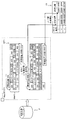
上述の如く構成された実施形態の一例としての分散処理システム1における分割ファイルの区切り位置の調整方法を、図5に示すフローチャート(ステップB1〜B12)に従って説明する。
Accordingly, the
The divided file whose data delimiter position has been corrected by the file management unit 12 (division processing unit 20) in this way is transferred to the
A method for adjusting the division position of the divided file in the distributed
ステップB1において、ファイル読込部21は、メモリ202の図示しないバッファ領域に、ユーザアプリケーション機能部11によって指定されたファイルのデータを格納する。
このステップB1における、ファイル読込部21によるファイルの読み込み処理を、図6に示すフローチャート(ステップB101〜B102)に従って説明する。
In step B <b> 1, the
The file reading process by the
ファイル先頭記録部22は、ステップB101においてメモリ202のバッファ領域を初期化した後、ステップB102において、ユーザアプリケーション機能部11によって指定されたファイルからバッファ単位でバッファ領域にデータを読み込む。
次に、図5のステップB2において、ファイル先頭記録部22が、ファイルの先頭位置を示す情報をノード間共有情報15に記録する。
The file
Next, in step B <b> 2 of FIG. 5, the file
このステップB2における、ファイル先頭記録部22による処理を、図7に示すフローチャート(ステップB201〜B203)に従って説明する。
先ず、ステップB201において、ファイル先頭記録部22は、処理中のタスク(分割ファイル)を特定するタスクIDを取得する。このタスクIDは、例えば、ユーザアプリケーション機能部11から取得してもよく、又、ファイル管理部12等が任意に設定してもよい。
The processing by the file
First, in step B201, the file
ステップB202において、ファイル先頭記録部22は、ノード間共有情報15に接続して、ステップB203において、タスクIDと処理対象の分割ファイルの先頭の位置を示す情報とをノード間共有情報15に記録する。
次に、図5のステップB3において、ファイル読込部21は、処理対象の分割ファイルにおける終端位置であるか否かを確認する。すなわち、バッファ領域に展開された処理対象の分割ファイルにおいて、処理中(走査中)位置を示すポインタが分割ファイルの終端に到達しているか否かを確認する。
In step B202, the file
Next, in step B3 of FIG. 5, the
確認の結果、分割ファイルの終端に到達していない場合には(ステップB3のNoルート参照)、ステップB4において、特定部23は、ポインタ位置から4バイトの値を読み出し、この4バイトの値に対して終端位置の判定処理を開始する。
ステップB5において、取得した4バイトの値(X)を符号なし整数値として、0<X<32768 の範囲内かどうか確認する。
As a result of the confirmation, if the end of the divided file has not been reached (see the No route in Step B3), in Step B4, the specifying
In step B5, the obtained 4-byte value (X) is set as an unsigned integer value, and it is confirmed whether or not 0 <X <32768.
4バイトの値が0<X<32768の範囲内の場合は(ステップB5のYesルート参照)、ステップB6において、取得した4バイトの値がレコード長(前側レコード長情報)であると仮定して、バッファ領域において、このレコード長分進んだ位置(バッファ位置)から4バイトの値を読み出す。
ステップB7において、ステップB4で取得した4バイトの値と、ステップB6でレコード長だけ進んだバッファ位置から取得した、後側レコード長情報と仮定される4バイトの値とが同一であるか否かを確認する。
If the 4-byte value is in the range of 0 <X <32768 (see the Yes route in step B5), it is assumed in step B6 that the acquired 4-byte value is the record length (front record length information). In the buffer area, a 4-byte value is read from the position (buffer position) advanced by this record length.
In step B7, whether or not the 4-byte value acquired in step B4 is the same as the assumed 4-byte value acquired from the buffer position advanced by the record length in step B6. Confirm.
ステップB4で取得した4バイトの値と、ステップB6で取得した4バイトの値とが同一である場合には(ステップB7のYesルート参照)、ステップB8に移行する。すなわち、ステップB4において、可変長レコードにおけるレコード長を正しく検出できたものとして、その可変長レコードからデータ(レコードデータ)を読み出し、ステップB3に戻る。 If the 4-byte value acquired in step B4 is the same as the 4-byte value acquired in step B6 (see Yes route in step B7), the process proceeds to step B8. That is, in step B4, assuming that the record length in the variable-length record has been correctly detected, data (record data) is read from the variable-length record, and the process returns to step B3.
一方、ステップB5において4バイトの値が0<X<32768の範囲外の場合や(ステップB5のNoルート参照)、ステップB4で取得した4バイトの値と、ステップB6で取得した4バイトの値とが同一でない場合には(ステップB7のNoルート参照)、ステップB9において、分割ファイルにおけるポインタ位置(現在位置)を走査方向に1バイト進めた後、ステップB4に戻る。 On the other hand, if the 4-byte value is outside the range of 0 <X <32768 in step B5 (see No route in step B5), the 4-byte value acquired in step B4 and the 4-byte value acquired in step B6 Are not the same (see the No route in step B7), the pointer position (current position) in the divided file is advanced by 1 byte in the scanning direction in step B9, and then the process returns to step B4.
また、ステップB3において、分割ファイルの終端に到達した場合には(ステップB3のYesルート参照)、ステップB10において、整合性判定部25による終端位置に対する判定(検証)とファイル終端記録部24による終端位置の記録が行なわれる。
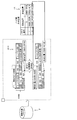
このステップB10における、整合性判定部25及びファイル終端記録部24による処理を、図8に示すフローチャート(ステップB111〜B116)に従って説明する。
If the end of the divided file has been reached in step B3 (see the Yes route in step B3), the determination (verification) of the end position by the
The processing by the
ステップB111において、整合性判定部25は、処理中のタスク(分割ファイル)を特定するタスクIDを取得する。
ステップB112において、整合性判定部25はノード間共有情報15にアクセスして、ステップB113において、ファイル終端記録部24が、ノード間共有情報15にタスクID及び確定レコード終端位置を記録する。
In step B <b> 111, the
In step B112, the
ステップB114において、整合性判定部25は、ステップB111において取得したタスクIDが1であるか否かを確認する。この確認の結果、タスクIDが1でない場合には(ステップB114のNoルート参照)ステップB115において、整合性判定部25は、ノード間共有情報15から、処理対象ファイルにおいて、処理中の分割ファイルよりも前側において連続する(すなわち、一つ前の)他の分割ファイルについての、確定レコード終端位置を読み出す。
In step B114, the
そして、ステップB116において、整合性判定部25は、この取得した一つ前の分割ファイルについての確定レコード終端位置の値に1を加算した値と、当該処理対象ファイルについて特定部23が特定した確定レコード先頭位置とを比較する。
取得した一つ前の分割ファイルについての確定レコード終端位置の値に1を加算した値と、当該処理対象ファイルについて特定部23が特定した確定レコード先頭位置とが一致した場合には(ステップB116のYesルート参照)、整合性があると判断して処理を終了する。
In step B116, the
If the value obtained by adding 1 to the value of the final record record end position for the previous divided file obtained matches the final record record start position specified by the
一方、取得した一つ前の分割ファイルについての確定レコード終端位置の値に1を加算した値と、当該処理対象ファイルについて特定部23が特定した確定レコード先頭位置とが一致しない場合には(ステップB116のNoルート参照)、整合性がないと判断して処理を終了する。
なお、整合性の判断結果(整合性ありもしくは整合性なし)は、その旨を示す情報(例えばフラグ)をメモリ202等の所定の記憶領域に記録することが望ましい。
On the other hand, if the value obtained by adding 1 to the value of the final record record end position for the previous previous divided file and the final record record position specified by the
Note that the consistency determination result (consistent or not consistent) is desirably recorded in a predetermined storage area such as the memory 202 (for example, a flag).
また、ステップB114における確認の結果、タスクIDが1である場合には(ステップB114のYesルート参照)、整合性判定部25は、整合性があると判断して処理を終了する。ファイルの先頭位置については、先行する分割ファイルは存在しないからである。
その後、図5におけるステップB11において、特定部23は、整合性判定部25による判定結果を参照して、整合性があると判断された場合には(ステップB11のYesルート参照)、処理を終了する。
If the task ID is 1 as a result of the confirmation in step B114 (see the Yes route in step B114), the
After that, in step B11 in FIG. 5, the specifying
また、整合性がないと判断された場合には(ステップB11のNoルート参照)、ステップB12において、特定部23は、分割ファイルにおけるポインタ位置(現在位置,確定レコード先頭位置)を走査方向に1バイトずらし、ステップB3に戻る。
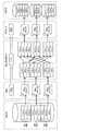
次に、上述の如く構成された実施形態の一例としての分散処理システム1における解析対象ファイルの分割処理を、図9〜図12を用いて例示する。図9は解析対象ファイルFを例示する図である。解析対象ファイルFは、NetCOBOLの可変長レコード順ファイルであり、以下においては、この図9に示すように、ファイル管理部12が、この解析対象ファイル(ファイル)Fを、3つの分割ファイルDF1〜DF3に分割する例を示す。各分割ファイルDF1〜DF3はそれぞれ64MBのデータサイズを有する。
If it is determined that there is no consistency (see No route in step B11), in step B12, the specifying
Next, the analysis target file division processing in the distributed
図10,図11及び図12は、それぞれ分割ファイルDF1,DF2及びDF3に対する処理を示す。
分割ファイルDF1はマップタスク1に(図10参照)、分割ファイルDF2はマップタスク2に(図11参照)、また、分割ファイルDF3はマップタスク3に(図12参照)、それぞれ割り当てられ、各マップタスク1〜3によりそれぞれ処理される。
10, FIG. 11 and FIG. 12 show the processing for the divided files DF1, DF2 and DF3, respectively.
The divided file DF1 is assigned to the map task 1 (see FIG. 10), the divided file DF2 is assigned to the map task 2 (see FIG. 11), and the divided file DF3 is assigned to the map task 3 (see FIG. 12). Processed by
また、各マップタスク1〜3において、割り当てられた分割ファイルDF1〜DF3は、それぞれに含まれる全ての可変長レコードが、それぞれ途中で分断されることがないように、上述した手法により区切り位置が調整される。
また、その際、各マップタスクにおいては、ファイル先頭記録部22が、区切り位置の調整後の分割ファイルの確定レコード先頭位置をノード間共有情報15の開始位置に格納し、又、確定レコード終端位置を、ノード間共有情報15の終端位置に格納する。
Further, in each
At that time, in each map task, the file
図10に例示するマップタスク1において処理される分割ファイルDF1は、解析対象ファイルFの先頭部分であるので、その確定レコード先頭位置は0であり、ノード間共有情報15のタスク番号1の開始位置には0が登録される。
また、区切り位置の調整後の分割ファイルDF1の終端位置が64MB+904B(バイト)であり、ノード間共有情報15のタスク番号1の終端位置には64MB+904Bが登録される。
Since the divided file DF1 processed in the
Further, the end position of the divided file DF1 after adjustment of the delimiter position is 64 MB + 904B (bytes), and 64 MB + 904B is registered as the end position of
図11に例示するマップタスク2において処理される分割ファイルDF2についても同様に、区切り位置の調整後の分割ファイルDF2の確定レコード先頭位置は64MB+905Bであり、ノード間共有情報15のタスク番号2の開始位置には64MB+905Bが登録される。
また、区切り位置の調整後の分割ファイルDF2の終端位置は128MB+381Bであり、ノード間共有情報15のタスク番号2の終端位置には128MB+381Bが登録される。
Similarly, for the divided file DF2 processed in the
Further, the end position of the divided file DF2 after adjustment of the delimiter position is 128 MB + 381B, and 128 MB + 381B is registered as the end position of
図12に例示するマップタスク3において処理される分割ファイルDF3についても同様に、区切り位置の調整後の分割ファイルDF3の確定レコード先頭位置は128MB+382Bであり、ノード間共有情報15のタスク番号3の開始位置には128MB+382Bが登録される。
また、区切り位置の調整後の分割ファイルDF3の終端位置は128MB+2079Bであり、ノード間共有情報15のタスク番号3の終端位置には128MB+2079Bが登録される。
Similarly, for the divided file DF3 processed in the
Further, the end position of the divided file DF3 after adjustment of the delimiter position is 128 MB + 2079B, and 128 MB + 2079B is registered as the end position of
このように、実施形態の一例としての分散処理システム1によれば、各マップタスクにおいて、特定部23が、バイナリデータである分割ファイルを、そのデータ構成の規則性を用いることで、その区切り位置を特定する。
例えば、分割ファイルを構成する可変長レコードが、データの前後にデータ長を示す情報を有している場合に、バッファ領域に格納された分割ファイルの先頭から走査して、レコード長を示すデータ(前側データ長情報)と想定される部分を検出する。そして、このレコード長と想定されるデータが示す値(データ長)だけ進んだバッファ位置にも、同一のレコード長と想定されるデータ(後側データ長情報)が検出された場合に、可変長レコードのレコード位置が検出できたとみなす。
As described above, according to the distributed
For example, when a variable length record constituting a split file has information indicating the data length before and after the data, data indicating the record length is scanned from the top of the split file stored in the buffer area ( The part assumed to be the front data length information) is detected. If the same record length (rear data length information) is detected at the buffer position advanced by the value (data length) indicated by the data assumed to be the record length, the variable length It is assumed that the record position of the record has been detected.
この可変長レコードのレコード位置の検出を、分割ファイルの終端まで繰り返し行ない、また、途中で不整合が検出された場合には、開始位置を1バイト進めた位置を新たな確定レコード先頭位置としてレコード位置の検出を再度行なう。これにより、データ区切りを検証することができる。
本分散処理システム1によれば、処理対象ファイル全体をその先頭から可変長レコードのレコード長を順次取り出して加算することなく、分割ファイルの区切り位置(分断位置)を容易に特定することができる。従って、マップタスク処理に要する時間を短縮することができ、処理を高速化することができる。
The detection of the record position of this variable-length record is repeated until the end of the split file, and if an inconsistency is detected in the middle, the record is set with the start position advanced by 1 byte as the new fixed record start position. The position is detected again. Thereby, the data delimiter can be verified.
According to the distributed
また、分割ファイルのデータ範囲を、確定レコード先頭位置を先頭とし、確定レコード終端位置を終端とするように修正することで、可変長レコードの途中にデータ区切りが位置することがなく、ブロック分割による泣き別れを防止することができる。
このように、処理対象のデータがバイナリデータであっても、データの規則性を利用し、且つ、規則性によるデータ区切りを検証することで、ブロック分割による泣き別れを防止することができる。
In addition, by modifying the data range of the split file so that the start position of the fixed record is the start and the end position of the fixed record is the end, the data break is not located in the middle of the variable-length record. Crying up can be prevented.
As described above, even if the data to be processed is binary data, it is possible to prevent crying due to block division by using the regularity of the data and verifying the data break due to the regularity.
また、各マップタスクにおいて、検証されたデータ区切りに基づき、その確定レコード先頭位置と確定レコード終端位置とをノード間共有情報15に記録する。そして、整合性判定部25が、このノード間共有情報15を参照して、隣り合う分割ファイルの終端位置が、確定レコード先頭位置と連続することを確認する。
分割ファイルがバイナリデータであるので、可変長レコードのデータ部分に、レコード長データに似たデータが存在するおそれがある。特定部23による区切り位置の検証時に、データ中のレコード長に似た値をレコード長と誤認し、更に、そのレコード長に似た値が示すデータ長だけ進んだ位置に、そのレコード長に似た値と同じ値が存在する場合に、区切り位置が誤検知されるおそれがある。
In each map task, the confirmed record start position and the confirmed record end position are recorded in the inter-node shared
Since the split file is binary data, there is a possibility that data similar to the record length data exists in the data portion of the variable length record. When the delimiter position is verified by the specifying
図13は実施形態の一例としての分散処理システム1の特定部23が犯しうる区切り位置の誤検知を例示する図である。
分割ファイルが格納されたバッファ領域から読み出した4バイトの値が32768未満の整数値であると、特定部23は、この値をレコード長と誤検知することになる。なお、図13中においては、便宜上、マップタスク2についてのみ示し、他のマップタスク1,3について図示を省略する。
FIG. 13 is a diagram exemplifying erroneous detection of a break position that can be committed by the specifying
If the 4-byte value read from the buffer area in which the divided file is stored is an integer value less than 32768, the specifying
図13に示す例では、バッファ領域から読み出した4バイトの値が“100”であったとする(符号C1参照)。なお、この図13に示す例においては、本来のデータ長は、図中で“1000”が記載されている部分である。
特定部23は、取得した4バイトの値(“100”)がレコード長であると仮定して、バッファ領域において、このレコード長分進んだ位置(バッファ位置)に、同一のレコード長データが存在するか確認する。
In the example shown in FIG. 13, it is assumed that the 4-byte value read from the buffer area is “100” (see reference C1). In the example shown in FIG. 13, the original data length is a portion where “1000” is described in the figure.
Assuming that the acquired 4-byte value (“100”) is the record length, the specifying
そして、この確認の結果、100バイト進んだ先の4バイトの領域に、偶然、同じく“100”が格納されている場合に(符号C2参照)、特定部23は、レコード位置が検出できたものと判断してしまう。また、これにより、可変長レコードからデータ部分とみなされるデータの読み込みが行なわれる(符号C3参照)。このようにして読み込まれたデータ中は、本来レコード長を示すデータ“1000”が含まれる等、正しいデータではない。
As a result of this confirmation, if “100” is accidentally stored in the 4-byte area that is advanced by 100 bytes (see C2), the specifying
また、当該分割ファイルにおけるそれ以降の部分について、各可変長レコードについて、ヘッダに含まれるレコード長とデータのレコード長との整合性を確認しながら読み込みを行なった結果、その終端まで不整合が検出されなかった場合には(符号C4参照)、読み込まれた誤ったデータが使用されることになる。
このような場合に、特定部23が確定レコード先頭位置及び確定レコード終端位置をノード間共有情報15に記録し、整合性判定部25が、他のノードによってノード間共有情報15に記録された、当該分割ファイルと連続する他の分割ファイルの確定レコード先頭位置や確定レコード終端位置との連続性を調査することで、特定部23による誤検知を検知することができるのである(符号C5参照)。
In addition, for each subsequent variable in the split file, each variable length record was read while checking the consistency between the record length included in the header and the record length of the data, and as a result, inconsistency was detected up to the end If not (see reference C4), the read erroneous data will be used.
In such a case, the identifying
このように、整合性判定部25がノード間による整合性の確認を行なうことにより、検出したデータ区切りがファイル全体で整合性を有することを確認することができ、信頼性を向上させることができる。
そして、開示の技術は上述した実施形態に限定されるものではなく、本実施形態の趣旨を逸脱しない範囲で種々変形して実施することができる。本実施形態の各構成及び各処理は、必要に応じて取捨選択することができ、あるいは適宜組み合わせてもよい。
As described above, the
The disclosed technology is not limited to the above-described embodiment, and various modifications can be made without departing from the spirit of the present embodiment. Each structure and each process of this embodiment can be selected as needed, or may be combined suitably.
例えば、上述した実施形態においては、整合性判定部25は、分割ファイルの先頭位置が、他のマップタスクで検出し記録した分割ファイルの終端位置と連続するか否かを確認することで整合性を確認しているが、これに限定されるものではない。
すなわち、整合性判定部25は、特定部23によって特定された分割ファイルの終端位置が正しいものであるか否かを検証してもよい。
For example, in the above-described embodiment, the
That is, the
整合性判定部25は、ノード間共有情報15を参照することで、特定部23によって特定された終端位置と、他のマップタスクで検出し記録した分割ファイルの先頭位置との整合性を確認することができる。
具体的には、整合性判定部25は、特定部23が特定した終端位置を、処理対象の分割ファイルに後続する他の分割ファイルを処理するマップタスクについてノード間共有情報15に記録されている分割ファイルの先頭位置(確認レコード先頭位置)と比較する。この比較の結果、後続する分割ファイルの確認レコード先頭位置が、当該マップタスクにおいて到達した終端位置と連続している場合に、整合性判定部25は整合性があると判断してもよい。
The
Specifically, the
また、上述した実施形態においては、処理対象のファイルがNetCOBOLの規格に沿った可変長レコードファイルである例を示しているが、これに限定されるものではなく、種々変形して実施することができる。
図14はMicroFocusのレコード順ファイルの構成を例示する図である。
この図14に例示するレコード順ファイルは、可変長レコードで構成され、各可変長レコードが、書き込まれたデータ(レコード)の前に、レコード長を含むレコードヘッダーを備えるとともに、データの後に最大3文字の埋め込み文字を備える。埋め込み文字は、次のレコードが4バイトの境界で開始されるようにするためのものである。
In the above-described embodiment, the file to be processed is an example of a variable-length record file that conforms to the NetCOBOL standard. However, the present invention is not limited to this, and various modifications can be made. it can.
FIG. 14 is a diagram illustrating the configuration of a record order file of MicroFocus.
The record sequential file illustrated in FIG. 14 includes variable-length records. Each variable-length record includes a record header including a record length before written data (record), and a maximum of 3 after the data. With embedded characters. The pad character is used to start the next record on a 4-byte boundary.
また、このレコード順ファイルには、128バイトのファイルヘッダーレコードが含まれる。
本分散処理システム1においては、処理対象ファイルがこの図14に例示するようなレコード順ファイルであってもよい。すなわち、特定部23は、そのデータ構造の規則性に基づいて、分割ファイルに含まれる可変長レコードの位置(データ区切り位置)を特定する。
The record sequential file includes a 128-byte file header record.
In the distributed
具体的には、特定部23は、バッファ領域に格納された分割ファイルにおいて、ヘッダに含まれるレコード長を読み取り、このレコード長分進んだ位置から所定サイズ(最大3文字)のデータを読み出し、このデータが埋め込み文字であるか否かを確認すればよい。
このように、処理対象のデータ構造に応じて、特定部23が、可変長レコードからのデータ読出位置や比較対象を適宜変更して実施することで、種々の処理対象データに適用することができる。
Specifically, the
As described above, according to the data structure of the processing target, the
また、上述した実施形態においては、複数のサーバ10を備え、これらの各サーバ10においてそれぞれマップタスクが実行されるとともに分割処理部20が分割ファイルの区切り位置の特定(修正)を行なっているが、これに限定されるものではない。例えば、1つのサーバ(情報処理装置)10において、複数のマップタスクを実行してもよく、これらのマップタスク毎に分割処理部20としてのプロセスを実行して分割ファイルの区切り位置の特定(修正)を行なってもよい。
In the above-described embodiment, a plurality of
以上の実施形態に関し、更に以下の付記を開示する。
(付記1)
コンピュータに、
処理対象である、バイナリデータが複数に分割された部分バイナリデータのデータ区切
り位置を、前記バイナリデータを構成する所定のデータの特性に基づき検出し、
検出したデータ区切り位置を示す情報を記憶手段に登録し、
前記記憶手段に登録された他の部分バイナリデータに関するデータ区切り位置を示す情
報に基づき、前記部分バイナリデータにおいて検出したデータ区切り位置が正当であるか
を判定する
処理を実行させることを特徴とする、データ分割処理プログラム。
Regarding the above embodiment, the following additional notes are disclosed.
(Appendix 1)
On the computer,
To be processed, the data delimiter position of the divided partial binary data binary data into a plurality, is detected based on the characteristics of a given data constituting said binary data,
Register information indicating the detected data break position in the storage means,
Based on the information indicating the data delimiter position related to the other partial binary data registered in the storage means, the process of determining whether the data delimiter position detected in the partial binary data is valid, Data division processing program.
(付記2)
前記処理対象の部分バイナリデータについて検出したデータ区切り位置と、前記記憶手段に登録された、前記バイナリデータにおいて前記処理対象の部分バイナリデータと隣接する部分バイナリデータについてのデータ区切り位置とが連続する場合に、検出したデータ区切り位置が正当であると判断する
処理を前記コンピュータに実行させることを特徴とする、付記1記載のデータ分割処理プログラム。
(Appendix 2)
When the data delimiter position detected for the partial binary data to be processed and the data delimiter position registered in the storage means for the partial binary data adjacent to the partial binary data to be processed in the binary data are continuous The data division processing program according to
(付記3)
前記部分バイナリデータを構成する個々の単位レコードに含まれるデータ長情報に基づき、当該部分バイナリデータの位置を特定する
処理を前記コンピュータに実行させることを特徴とする、付記1又は2記載のデータ分割処理プログラム。
(Appendix 3)
The data division according to
(付記4)
正当であると判断された前記データ区切り位置に基づき、前記バイナリデータのデータ区切り位置を確定する
処理を前記コンピュータに実行させることを特徴とする、付記1〜3のいずれか1項に記載のデータ分割処理プログラム。
(Appendix 4)
The data according to any one of
(付記5)
バイナリデータを複数に分割した部分バイナリデータを処理するデータ分割処理装置であって、
処理対象の部分バイナリデータのデータ区切り位置を、前記バイナリデータを構成する所定のデータの特性に基づき検出する検出部と、
検出したデータ区切り位置を示す情報を記憶手段に登録する登録部と、
前記記憶手段に登録された他の部分バイナリデータに関するデータ区切り位置を示す情報に基づき、前記部分バイナリデータにおいて検出したデータ区切り位置が正当であるかを判定する判定部と、
を備えることを特徴とする、データ分割処理装置。
(Appendix 5)
A data division processing device for processing partial binary data obtained by dividing binary data into a plurality of pieces,
A detection unit for detecting a data break position of the partial binary data to be processed based on characteristics of predetermined data constituting the binary data;
A registration unit for registering information indicating the detected data break position in the storage means;
A determination unit that determines whether the data delimiter position detected in the partial binary data is valid based on information indicating a data delimiter position related to the other partial binary data registered in the storage unit;
A data division processing apparatus comprising:
(付記6)
前記判定部が、
前記処理対象の部分バイナリデータについて検出したデータ区切り位置と、前記記憶手段に登録された、前記バイナリデータにおいて前記処理対象の部分バイナリデータと隣接する部分バイナリデータについてのデータ区切り位置とが連続する場合に、検出したデータ区切り位置が正当であると判断する
ことを特徴とする、付記5記載のデータ分割処理装置。
(Appendix 6)
Said-size constant section,
When the data delimiter position detected for the partial binary data to be processed and the data delimiter position registered in the storage means for the partial binary data adjacent to the partial binary data to be processed in the binary data are continuous The data division processing device according to appendix 5, wherein the detected data delimiter position is determined to be valid.
(付記7)
前記検出部が、前記部分バイナリデータを構成する個々の単位レコードに含まれるデータ長情報に基づき、当該部分バイナリデータの位置を特定する
ことを特徴とする、付記5又は6記載のデータ分割処理装置。
(付記8)
正当であると判断された前記データ区切り位置に基づき、前記バイナリデータのデータ区切り位置を確定する確定部
を備えることを特徴とする、付記5〜7のいずれか1項に記載のデータ分割処理装置。
(Appendix 7)
The data division processing device according to
(Appendix 8)
The data division processing device according to any one of appendices 5 to 7, further comprising a determination unit that determines a data separation position of the binary data based on the data separation position determined to be valid. .
(付記9)
バイナリデータを複数に分割して複数の処理部により処理する分割処理方法であって、
前記複数の処理部のそれぞれに、前記バイナリデータの一部である部分バイナリデータをそれぞれ割り当て、
前記複数の処理部はそれぞれ、割り当てられた部分バイナリデータのデータ区切り位置を、前記バイナリデータを構成する所定のデータの特性に基づき検出するとともに、検出したデータ区切り位置を示す情報を記憶手段に登録し、
前記複数の処理部はそれぞれ、他の処理部により前記記憶手段に登録されたデータ区切り位置を示す情報に基づき、前記部分バイナリデータにおいて検出したデータ区切り位置が正当であるかを判定する
ことを特徴とする、データ分割処理方法。
(Appendix 9)
A division processing method in which binary data is divided into a plurality of parts and processed by a plurality of processing units,
Assigning partial binary data that is a part of the binary data to each of the plurality of processing units,
Each of the plurality of processing units detects a data break position of the allocated partial binary data based on characteristics of predetermined data constituting the binary data, and registers information indicating the detected data break position in the storage unit And
Each of the plurality of processing units determines whether a data delimiter position detected in the partial binary data is valid based on information indicating a data delimiter position registered in the storage unit by another processing unit. A data division processing method.
(付記10)
前記処理対象の部分バイナリデータについて検出したデータ区切り位置と、前記記憶手段に登録された、前記バイナリデータにおいて前記処理対象の部分バイナリデータと隣接する部分バイナリデータについてのデータ区切り位置とが連続する場合に、検出したデータ区切り位置が正当であると判断する
ことを特徴とする、付記9記載のデータ分割処理方法。
(Appendix 10)
When the data delimiter position detected for the partial binary data to be processed and the data delimiter position registered in the storage means for the partial binary data adjacent to the partial binary data to be processed in the binary data are continuous The data division processing method according to appendix 9, wherein the detected data delimiter position is determined to be valid.
(付記11)
前記部分バイナリデータを構成する個々の単位レコードに含まれるデータ長情報に基づき、当該部分バイナリデータの位置を特定する
ことを特徴とする、付記9又は10記載のデータ分割処理方法。
(付記12)
正当であると判断された前記データ区切り位置に基づき、前記バイナリデータのデータ区切り位置を確定する
ことを特徴とする、付記9〜11のいずれか1項に記載のデータ分割処理方法。
(Appendix 11)
11. The data division processing method according to
(Appendix 12)
The data division processing method according to any one of appendices 9 to 11, wherein the data division position of the binary data is determined based on the data division position determined to be valid.
1 分散処理システム
10,10−1〜10−4 サーバ(処理部,データ分割処理装置)
11 ユーザアプリケーション機能部
12 ファイル管理部
13 タスクトラッカ
14 ジョブトラッカ
15 ノード間共有情報
20 分散処理部
21 ファイル読込部
22 ファイル先頭記録部(登録部)
23 特定部(検出部,確定部)
24 ファイル終端記録部(登録部)
25 整合性判定部(判定部)
201 CPU
202 メモリ(記憶手段)
205 表示装置
206 キーボード
207 マウス
208 記憶装置
50 ネットワーク
1 distributed
DESCRIPTION OF
23 Specific part (detection part, determination part)
24 File end recording part (registration part)
25 Consistency determination unit (determination unit)
201 CPU
202 Memory (storage means)
205
Claims (5)
処理対象である、バイナリデータが複数に分割された部分バイナリデータのデータ区切り位置を、前記バイナリデータを構成する所定のデータの特性に基づき検出し、
検出したデータ区切り位置を示す情報を記憶手段に登録し、
前記記憶手段に登録された他の部分バイナリデータに関するデータ区切り位置を示す情報に基づき、前記部分バイナリデータにおいて検出したデータ区切り位置が正当であるかを判定し、
前記処理対象の部分バイナリデータについて検出したデータ区切り位置と、前記記憶手段に登録された、前記バイナリデータにおいて前記処理対象の部分バイナリデータと隣接する部分バイナリデータについてのデータ区切り位置とが連続する場合に、検出したデータ区切り位置が正当であると判断する
処理を実行させることを特徴とする、データ分割処理プログラム。 On the computer,
The processing target, the data separator position of the partial binary data divided into a plurality of binary data is detected based on the characteristics of the predetermined data constituting the binary data,
Register information indicating the detected data break position in the storage means,
Based on the information indicating the data delimiter position regarding the other partial binary data registered in the storage means, determine whether the data delimiter position detected in the partial binary data is valid ,
When the data delimiter position detected for the partial binary data to be processed and the data delimiter position registered in the storage means for the partial binary data adjacent to the partial binary data to be processed in the binary data are continuous And a data division processing program for executing a process of determining that the detected data delimiter position is valid .
処理を前記コンピュータに実行させることを特徴とする、請求項1記載のデータ分割処理プログラム。 Based on said data length information included in the individual unit record constituting the partial binary data, characterized in that to execute the process of specifying the position of the partial binary data to the computer, data division of claim 1 Symbol placement Processing program.
処理を前記コンピュータに実行させることを特徴とする、請求項1又は2記載のデータ分割処理プログラム。 3. The data division processing program according to claim 1, wherein the computer executes a process of determining a data separation position of the binary data based on the data separation position determined to be valid. 4.
処理対象の部分バイナリデータのデータ区切り位置を、前記バイナリデータを構成する所定のデータの特性に基づき検出する検出部と、
検出したデータ区切り位置を示す情報を記憶手段に登録する登録部と、
前記記憶手段に登録された他の部分バイナリデータに関するデータ区切り位置を示す情報に基づき、前記部分バイナリデータにおいて検出したデータ区切り位置が正当であるかを判定する判定部と、
を備え、
前記判定部は、前記処理対象の部分バイナリデータについて検出したデータ区切り位置と、前記記憶手段に登録された、前記バイナリデータにおいて前記処理対象の部分バイナリデータと隣接する部分バイナリデータについてのデータ区切り位置とが連続する場合に、検出したデータ区切り位置が正当であると判断することを特徴とする、データ分割処理装置。 A data division processing device for processing partial binary data obtained by dividing binary data into a plurality of pieces,
A detection unit for detecting a data break position of the partial binary data to be processed based on characteristics of predetermined data constituting the binary data;
A registration unit for registering information indicating the detected data break position in the storage means;
A determination unit that determines whether the data delimiter position detected in the partial binary data is valid based on information indicating a data delimiter position related to the other partial binary data registered in the storage unit;
Equipped with a,
The determination unit includes a data break position detected for the partial binary data to be processed and a data break position for partial binary data that is registered in the storage unit and is adjacent to the partial binary data to be processed in the binary data. A data division processing device characterized by determining that the detected data delimiter position is valid when the two are consecutive .
前記複数の処理部のそれぞれに、前記バイナリデータの一部である部分バイナリデータをそれぞれ割り当て、
前記複数の処理部はそれぞれ、割り当てられた部分バイナリデータのデータ区切り位置を、前記バイナリデータを構成する所定のデータの特性に基づき検出するとともに、検出したデータ区切り位置を示す情報を記憶手段に登録し、
前記複数の処理部はそれぞれ、他の処理部により前記記憶手段に登録されたデータ区切り位置を示す情報に基づき、前記部分バイナリデータにおいて検出したデータ区切り位置が正当であるかを判定し、
前記処理対象の部分バイナリデータについて検出したデータ区切り位置と、前記記憶手段に登録された、前記バイナリデータにおいて前記処理対象の部分バイナリデータと隣接する部分バイナリデータについてのデータ区切り位置とが連続する場合に、検出したデータ区切り位置が正当であると判断する
ことを特徴とする、データ分割処理方法。 A division processing method in which binary data is divided into a plurality of parts and processed by a plurality of processing units,
Assigning partial binary data that is a part of the binary data to each of the plurality of processing units,
Each of the plurality of processing units detects a data break position of the allocated partial binary data based on characteristics of predetermined data constituting the binary data, and registers information indicating the detected data break position in the storage unit And
Each of the plurality of processing units determines whether the data delimiter position detected in the partial binary data is valid based on the information indicating the data delimiter position registered in the storage unit by another processing unit ,
When the data delimiter position detected for the partial binary data to be processed and the data delimiter position registered in the storage means for the partial binary data adjacent to the partial binary data to be processed in the binary data are continuous In addition, it is determined that the detected data break position is valid .
Priority Applications (2)
| Application Number | Priority Date | Filing Date | Title |
|---|---|---|---|
| JP2014045042A JP6260359B2 (en) | 2014-03-07 | 2014-03-07 | Data division processing program, data division processing device, and data division processing method |
| US14/613,442 US10102217B2 (en) | 2014-03-07 | 2015-02-04 | Non-transitory computer-readable recording medium having stored therein data dividing program, data dividing apparatus, and data dividing method |
Applications Claiming Priority (1)
| Application Number | Priority Date | Filing Date | Title |
|---|---|---|---|
| JP2014045042A JP6260359B2 (en) | 2014-03-07 | 2014-03-07 | Data division processing program, data division processing device, and data division processing method |
Publications (2)
| Publication Number | Publication Date |
|---|---|
| JP2015170170A JP2015170170A (en) | 2015-09-28 |
| JP6260359B2 true JP6260359B2 (en) | 2018-01-17 |
Family
ID=54017548
Family Applications (1)
| Application Number | Title | Priority Date | Filing Date |
|---|---|---|---|
| JP2014045042A Active JP6260359B2 (en) | 2014-03-07 | 2014-03-07 | Data division processing program, data division processing device, and data division processing method |
Country Status (2)
| Country | Link |
|---|---|
| US (1) | US10102217B2 (en) |
| JP (1) | JP6260359B2 (en) |
Cited By (1)
| Publication number | Priority date | Publication date | Assignee | Title |
|---|---|---|---|---|
| JP7021035B2 (en) | 2018-09-18 | 2022-02-16 | 株式会社東芝 | Permanent magnets, rotary electric machines, and cars |
Families Citing this family (8)
| Publication number | Priority date | Publication date | Assignee | Title |
|---|---|---|---|---|
| CN105205174B (en) * | 2015-10-14 | 2019-10-11 | 北京百度网讯科技有限公司 | Document handling method and device for distributed system |
| JP6242540B1 (en) * | 2016-03-17 | 2017-12-06 | 株式会社日立製作所 | Data conversion system and data conversion method |
| US11146613B2 (en) * | 2016-07-29 | 2021-10-12 | International Business Machines Corporation | Distributed computing on document formats |
| JP6772883B2 (en) | 2017-02-15 | 2020-10-21 | 富士通株式会社 | Reading program, reading method and information processing device |
| US11055018B2 (en) * | 2019-06-25 | 2021-07-06 | Western Digital Technologies, Inc. | Parallel storage node processing of data functions |
| US10990324B2 (en) | 2019-06-25 | 2021-04-27 | Western Digital Technologies, Inc. | Storage node processing of predefined data functions |
| US11314593B2 (en) | 2019-06-25 | 2022-04-26 | Western Digital Technologies, Inc. | Storage node processing of data functions using overlapping symbols |
| US11281531B2 (en) * | 2019-06-25 | 2022-03-22 | Western Digital Technologies, Inc. | Serial storage node processing of data functions |
Family Cites Families (13)
| Publication number | Priority date | Publication date | Assignee | Title |
|---|---|---|---|---|
| JPH0362137A (en) | 1989-07-28 | 1991-03-18 | Nec Corp | Long and large data storing method by variable length block group |
| JP2975650B2 (en) * | 1989-11-01 | 1999-11-10 | 富士通株式会社 | Procedure management device |
| KR100191262B1 (en) * | 1990-07-23 | 1999-06-15 | 아끼구사 나오유끼 | Terminal device |
| US5592342A (en) | 1994-05-23 | 1997-01-07 | Quantum Corporation | Method for packing variable size user data records into fixed size blocks on a storage medium |
| JP2004287525A (en) * | 2003-03-19 | 2004-10-14 | Ricoh Co Ltd | Information providing device, method and program |
| US8214517B2 (en) * | 2006-12-01 | 2012-07-03 | Nec Laboratories America, Inc. | Methods and systems for quick and efficient data management and/or processing |
| US8694703B2 (en) * | 2010-06-09 | 2014-04-08 | Brocade Communications Systems, Inc. | Hardware-accelerated lossless data compression |
| JP2012118669A (en) | 2010-11-30 | 2012-06-21 | Ntt Docomo Inc | Load distribution processing system and load distribution processing method |
| JP5735654B2 (en) * | 2011-10-06 | 2015-06-17 | 株式会社日立製作所 | Deduplication method for stored data, deduplication apparatus for stored data, and deduplication program |
| US9164688B2 (en) * | 2012-07-03 | 2015-10-20 | International Business Machines Corporation | Sub-block partitioning for hash-based deduplication |
| US9626373B2 (en) * | 2012-10-01 | 2017-04-18 | Western Digital Technologies, Inc. | Optimizing data block size for deduplication |
| WO2014184857A1 (en) * | 2013-05-13 | 2014-11-20 | 株式会社日立製作所 | Duplication elimination system and method therefor |
| US9100042B2 (en) * | 2013-06-20 | 2015-08-04 | International Business Machines Corporation | High throughput decoding of variable length data symbols |
-
2014
- 2014-03-07 JP JP2014045042A patent/JP6260359B2/en active Active
-
2015
- 2015-02-04 US US14/613,442 patent/US10102217B2/en active Active
Cited By (1)
| Publication number | Priority date | Publication date | Assignee | Title |
|---|---|---|---|---|
| JP7021035B2 (en) | 2018-09-18 | 2022-02-16 | 株式会社東芝 | Permanent magnets, rotary electric machines, and cars |
Also Published As
| Publication number | Publication date |
|---|---|
| JP2015170170A (en) | 2015-09-28 |
| US20150254287A1 (en) | 2015-09-10 |
| US10102217B2 (en) | 2018-10-16 |
Similar Documents
| Publication | Publication Date | Title |
|---|---|---|
| JP6260359B2 (en) | Data division processing program, data division processing device, and data division processing method | |
| US20200356901A1 (en) | Target variable distribution-based acceptance of machine learning test data sets | |
| CN109034809B (en) | Block chain generation method and device, block chain node and storage medium | |
| CN107577427B (en) | data migration method, device and storage medium for blockchain system | |
| US10778246B2 (en) | Managing compression and storage of genomic data | |
| US20190245919A1 (en) | Method and apparatus for information processing, server and computer readable medium | |
| US10838767B2 (en) | Distributed computing utilizing a recovery site | |
| JP2021518021A (en) | Data processing methods, equipment and computer readable storage media | |
| US20180260433A1 (en) | Information processing apparatus and control method for information processing apparatus | |
| US20110246832A1 (en) | Processing apparatus, data migration method, and computer-readable recording medium having data migration program recorded thereon | |
| CN105701405B (en) | The system and method that anti-virus inspection is carried out to the machine image of software program collection | |
| CN105892954A (en) | Data storage method and device based on multiple copies | |
| WO2013108745A1 (en) | Storage device, control method for same, and program | |
| US20180157671A1 (en) | Accessing objects in an erasure code supported object storage environment | |
| US20200249871A1 (en) | Methods, devices, and a computer program product for processing an access request and updating a storage system | |
| JP2009093491A (en) | Verification-scenario generating program, recording medium recording the program, verification-scenario generating apparatus, and verification-scenario generating method | |
| JP5751041B2 (en) | Storage device, storage method and program | |
| JP6421568B2 (en) | Information processing apparatus and information processing program | |
| US11360710B2 (en) | Storage control device, distributed storage system, and non-transitory computer-readable storage medium for storing storage control program | |
| US20170220571A1 (en) | Information Processing Device, Information Processing Method, and Non-Transitory Computer Readable Medium Storing Information Processing Program | |
| JP5842437B2 (en) | Information processing apparatus and information processing program | |
| US8635699B1 (en) | Performance optimization for scanning of digital content on read-only optical media | |
| CN104077304B (en) | file identification system and method | |
| JP5183132B2 (en) | Rule-based system and rule application program | |
| JP5928714B2 (en) | Information processing apparatus and information processing program |
Legal Events
| Date | Code | Title | Description |
|---|---|---|---|
| A621 | Written request for application examination |
Free format text: JAPANESE INTERMEDIATE CODE: A621 Effective date: 20161102 |
|
| A977 | Report on retrieval |
Free format text: JAPANESE INTERMEDIATE CODE: A971007 Effective date: 20170830 |
|
| A131 | Notification of reasons for refusal |
Free format text: JAPANESE INTERMEDIATE CODE: A131 Effective date: 20170905 |
|
| A521 | Written amendment |
Free format text: JAPANESE INTERMEDIATE CODE: A523 Effective date: 20171106 |
|
| TRDD | Decision of grant or rejection written | ||
| A01 | Written decision to grant a patent or to grant a registration (utility model) |
Free format text: JAPANESE INTERMEDIATE CODE: A01 Effective date: 20171114 |
|
| A61 | First payment of annual fees (during grant procedure) |
Free format text: JAPANESE INTERMEDIATE CODE: A61 Effective date: 20171127 |
|
| R150 | Certificate of patent or registration of utility model |
Ref document number: 6260359 Country of ref document: JP Free format text: JAPANESE INTERMEDIATE CODE: R150 |