JP6257148B2 - Image forming apparatus - Google Patents
Image forming apparatus Download PDFInfo
- Publication number
- JP6257148B2 JP6257148B2 JP2013031426A JP2013031426A JP6257148B2 JP 6257148 B2 JP6257148 B2 JP 6257148B2 JP 2013031426 A JP2013031426 A JP 2013031426A JP 2013031426 A JP2013031426 A JP 2013031426A JP 6257148 B2 JP6257148 B2 JP 6257148B2
- Authority
- JP
- Japan
- Prior art keywords
- light
- unit
- color
- measurement
- wavelength
- Prior art date
- Legal status (The legal status is an assumption and is not a legal conclusion. Google has not performed a legal analysis and makes no representation as to the accuracy of the status listed.)
- Expired - Fee Related
Links
- 238000005259 measurement Methods 0.000 claims description 47
- 238000001514 detection method Methods 0.000 claims description 42
- 230000003595 spectral effect Effects 0.000 claims description 22
- 230000015572 biosynthetic process Effects 0.000 claims description 5
- 238000000034 method Methods 0.000 description 28
- 238000006243 chemical reaction Methods 0.000 description 25
- 238000004364 calculation method Methods 0.000 description 18
- 230000008859 change Effects 0.000 description 18
- 230000007246 mechanism Effects 0.000 description 18
- 238000012545 processing Methods 0.000 description 18
- 238000012546 transfer Methods 0.000 description 13
- 230000008569 process Effects 0.000 description 9
- 238000010586 diagram Methods 0.000 description 6
- 230000006870 function Effects 0.000 description 6
- 230000007423 decrease Effects 0.000 description 4
- 238000010438 heat treatment Methods 0.000 description 4
- 230000003287 optical effect Effects 0.000 description 4
- 239000003086 colorant Substances 0.000 description 3
- 238000012937 correction Methods 0.000 description 3
- 238000012360 testing method Methods 0.000 description 3
- 230000009471 action Effects 0.000 description 2
- 238000002474 experimental method Methods 0.000 description 2
- 239000004065 semiconductor Substances 0.000 description 2
- 101150004913 GAMT gene Proteins 0.000 description 1
- 230000032683 aging Effects 0.000 description 1
- 239000000919 ceramic Substances 0.000 description 1
- 230000001419 dependent effect Effects 0.000 description 1
- 238000009795 derivation Methods 0.000 description 1
- 238000013461 design Methods 0.000 description 1
- 230000006866 deterioration Effects 0.000 description 1
- 238000011161 development Methods 0.000 description 1
- 230000018109 developmental process Effects 0.000 description 1
- 238000007599 discharging Methods 0.000 description 1
- 238000001035 drying Methods 0.000 description 1
- 238000005265 energy consumption Methods 0.000 description 1
- 230000007613 environmental effect Effects 0.000 description 1
- 238000005286 illumination Methods 0.000 description 1
- 230000010354 integration Effects 0.000 description 1
- 238000013507 mapping Methods 0.000 description 1
- 229910052751 metal Inorganic materials 0.000 description 1
- 239000002184 metal Substances 0.000 description 1
- TWNQGVIAIRXVLR-UHFFFAOYSA-N oxo(oxoalumanyloxy)alumane Chemical compound O=[Al]O[Al]=O TWNQGVIAIRXVLR-UHFFFAOYSA-N 0.000 description 1
- 238000003825 pressing Methods 0.000 description 1
- 238000009877 rendering Methods 0.000 description 1
- 238000000926 separation method Methods 0.000 description 1
- 238000004088 simulation Methods 0.000 description 1
- 238000000859 sublimation Methods 0.000 description 1
- 230000008022 sublimation Effects 0.000 description 1
- 238000011144 upstream manufacturing Methods 0.000 description 1
Images


Classifications
-
- G—PHYSICS
- G01—MEASURING; TESTING
- G01J—MEASUREMENT OF INTENSITY, VELOCITY, SPECTRAL CONTENT, POLARISATION, PHASE OR PULSE CHARACTERISTICS OF INFRARED, VISIBLE OR ULTRAVIOLET LIGHT; COLORIMETRY; RADIATION PYROMETRY
- G01J3/00—Spectrometry; Spectrophotometry; Monochromators; Measuring colours
- G01J3/02—Details
- G01J3/0286—Constructional arrangements for compensating for fluctuations caused by temperature, humidity or pressure, or using cooling or temperature stabilization of parts of the device; Controlling the atmosphere inside a spectrometer, e.g. vacuum
-
- G—PHYSICS
- G01—MEASURING; TESTING
- G01J—MEASUREMENT OF INTENSITY, VELOCITY, SPECTRAL CONTENT, POLARISATION, PHASE OR PULSE CHARACTERISTICS OF INFRARED, VISIBLE OR ULTRAVIOLET LIGHT; COLORIMETRY; RADIATION PYROMETRY
- G01J3/00—Spectrometry; Spectrophotometry; Monochromators; Measuring colours
- G01J3/46—Measurement of colour; Colour measuring devices, e.g. colorimeters
- G01J3/50—Measurement of colour; Colour measuring devices, e.g. colorimeters using electric radiation detectors
- G01J3/502—Measurement of colour; Colour measuring devices, e.g. colorimeters using electric radiation detectors using a dispersive element, e.g. grating, prism
-
- G—PHYSICS
- G03—PHOTOGRAPHY; CINEMATOGRAPHY; ANALOGOUS TECHNIQUES USING WAVES OTHER THAN OPTICAL WAVES; ELECTROGRAPHY; HOLOGRAPHY
- G03G—ELECTROGRAPHY; ELECTROPHOTOGRAPHY; MAGNETOGRAPHY
- G03G15/00—Apparatus for electrographic processes using a charge pattern
- G03G15/04—Apparatus for electrographic processes using a charge pattern for exposing, i.e. imagewise exposure by optically projecting the original image on a photoconductive recording material
- G03G15/043—Apparatus for electrographic processes using a charge pattern for exposing, i.e. imagewise exposure by optically projecting the original image on a photoconductive recording material with means for controlling illumination or exposure
Landscapes
- Physics & Mathematics (AREA)
- Spectroscopy & Molecular Physics (AREA)
- General Physics & Mathematics (AREA)
- Spectrometry And Color Measurement (AREA)
- Facsimile Image Signal Circuits (AREA)
- Color Image Communication Systems (AREA)
- Color Electrophotography (AREA)
- Image Processing (AREA)
Description
本願発明は、色を測定する機能を備えた測定装置、および画像形成装置に関する。 The present invention relates to a measuring apparatus having a function of measuring a color and an image forming apparatus.
昨今において普及している画像形成装置(以下、プリンタと呼ぶ)の画像品質(以下、画質と呼ぶ)には、粒状性、面内一様性、文字品位、色再現性(色安定性を含む)など様々である。そのうち最も重要な要素として色再現性が挙げられる。 Image quality (hereinafter referred to as image quality) of image forming apparatuses (hereinafter referred to as printers) that have been widely used in recent years includes graininess, in-plane uniformity, character quality, and color reproducibility (including color stability). ) Etc. Among them, the most important factor is color reproducibility.
色の再現性については同機種間だけでなく、異機種間、他方式による画像形成装置あるいは画像表示装置との色の違いも問題になることから、これら機器同士のカラーマッチングを行うため、ICC(International Color Consortium)プロファイルと呼ばれる多次元LUT(Look Up Table)を作成するソフトウェアと測定器が市販されている。 Regarding color reproducibility, color differences between not only the same model but also between different models and image forming apparatuses or image display apparatuses according to other methods are also a problem. Software and a measuring instrument for creating a multidimensional LUT (Look Up Table) called an (International Color Consortium) profile are commercially available.
図5に示すように、各ICCプロファイルの内容は、測定器を用いたパッチの色測定に基づき、機器に依存しない色空間に対応付けて校正される。色空間には例えば、CIE L*a*b*色空間(CIEは国際照明委員;Commission Internationale de l’Eclairageの略)が挙げられる。これにより、異なる機器間においても、プリントする色を一致させることができる。そして、画像形成装置等に備えられたCMM(Color Management Module)は、これらのプロファイルを用いて色変換を行うことによりプリント・データを作成することができる。 As shown in FIG. 5, the contents of each ICC profile are calibrated in association with a color space that does not depend on the device, based on the color measurement of the patch using a measuring instrument. Examples of the color space include a CIE L * a * b * color space (CIE is an International Illumination Committee; abbreviation for Commission Internationale de l'Eclairage). This makes it possible to match the colors to be printed between different devices. A CMM (Color Management Module) provided in the image forming apparatus or the like can create print data by performing color conversion using these profiles.
特許文献1では、シート上に形成したパッチ像を、光源と回折格子と位置検出センサからなるカラーセンサにて検出し、検出精度を向上させたインラインでの測定器構成が提案されている。カラーセンサからの検出値を分光反射率に変換し、三刺激値などを考慮してCIE Labに変換することができる。特許文献1におけるカラーセンサは、環境温度の変化による光源の出力変動などの変動要因により、色検出精度が悪化する。そこで、カラーセンサの対向位置に配置した白色基準板によってキャリブレーションを行い、カラーセンサの検出値を補正する方式がある。キャリブレーション方法としては、パッチ像の色測定を実施する前、あるいは、後で白色基準板の反射光を測定し、測定値を基に計算を行う。白色基準板で計算する場合の分光反射率の計算方法としては、白色基準板の反射光量W(λ)、パッチの反射光量P(λ)とした場合、(式1)で表わされる。
![]()
白色基準板は、測定波長領域の光を波長に依存せず略同一の反射率で反射するため、白色基準板からの反射光量W(λ)はパッチ像への入射光量と等価とみなせる。したがって、パッチ像への入射光量(すなわちW(λ))と、反射光量P(λ)の双方を測定することで、パッチの分光反射率R(λ)は、光源の出力変動の影響を受けず導出できる。
![]()
Since the white reference plate reflects light in the measurement wavelength region with substantially the same reflectance without depending on the wavelength, the reflected light amount W (λ) from the white reference plate can be regarded as equivalent to the incident light amount on the patch image. Therefore, by measuring both the amount of light incident on the patch image (that is, W (λ)) and the amount of reflected light P (λ), the spectral reflectance R (λ) of the patch is affected by the output fluctuation of the light source. Can be derived.
一方、カラーセンサには、複数の受光素子を配列したラインセンサが含まれる。ここで、部品組み付け等のばらつきによりラインセンサの各素子と各光波長との位置関係がずれ、測定時に色波長成分を誤検知する可能性がある。以降この現象を波長誤検知と呼ぶ。波長誤検知を防ぐためには、例えば工場での調整行程によってラインセンサの各素子と入射する光波長の関係とを調整する方法が考えられる。 On the other hand, the color sensor includes a line sensor in which a plurality of light receiving elements are arranged. Here, the positional relationship between each element of the line sensor and each light wavelength is shifted due to variations in assembly of components, and the color wavelength component may be erroneously detected during measurement. Hereinafter, this phenomenon is referred to as wavelength erroneous detection. In order to prevent erroneous wavelength detection, for example, a method of adjusting each element of the line sensor and the relationship between incident light wavelengths by an adjustment process in a factory is conceivable.
しかしながらカラーセンサは、温度変化によって各部品を保持する保持部材が熱膨張することにより、各部品の位置関係にズレが生じてしまい、検出する色味(L*a*b値)が変化し測定誤差となる。波長誤検知量をΔλとすると、白色基準板の反射光量W(λ)、パッチの反射光量P(λ)、分光反射率R(λ)は、式(2)の関係となる。 However, in the color sensor, when the holding member that holds each component is thermally expanded due to a temperature change, the positional relationship between the components is shifted, and the detected color (L * a * b value) changes. It becomes an error. Assuming that the wavelength misdetection amount is Δλ, the reflected light amount W (λ) of the white reference plate, the reflected light amount P (λ) of the patch, and the spectral reflectance R (λ) have the relationship of Expression (2).
![]()
Δλを求める方法としては、ラインセンサで検出された光出力ピーク位置のシフト量を求める方法が考えられる。初期調整時においてラインセンサの検出値から、最も出力の高いピーク出力が得られたラインセンサの受光素子を記憶し、温度変化時にピーク出力の移動量を検出することで、波長シフト量を検出できる。このように波長誤検知量Δλの検出と式(2)の演算によってセンサ起因の波長シフト分を補正できる。
![]()
As a method for obtaining Δλ, a method for obtaining the shift amount of the light output peak position detected by the line sensor can be considered. The wavelength shift amount can be detected by storing the light receiving element of the line sensor that obtained the highest peak output from the detection value of the line sensor at the time of initial adjustment, and detecting the amount of movement of the peak output when the temperature changes . Thus, the wavelength shift due to the sensor can be corrected by detecting the erroneous wavelength detection amount Δλ and calculating the equation (2).
しかしながら、ピーク検出による波長誤検知量Δλの導出方法には、以下の問題があった。温度が変化によって、光源の波長変動とセンサ側での波長誤検知が同時に起こると、ラインセンサで検出されるピークの移動量の中には、光源の波長変動量と、ラインセンサ側での波長誤検知量Δλが混在する。そのため、波長誤検知量Δλだけを求めることができなくなる。そして、波長誤検知量Δλが正確に検知できないことから、波長誤検知量Δλの補正が正確に行えず、測定誤差が発生するという問題があった。 However, the method of deriving the erroneous wavelength detection amount Δλ by peak detection has the following problems. If the wavelength change of the light source and the wavelength detection error on the sensor side occur simultaneously due to the temperature change, the peak movement detected by the line sensor includes the wavelength fluctuation amount of the light source and the wavelength on the line sensor side. Misdetection amount Δλ is mixed. Therefore, it becomes impossible to obtain only the wavelength erroneous detection amount Δλ. Since the erroneous wavelength detection amount Δλ cannot be accurately detected, the erroneous wavelength detection amount Δλ cannot be corrected accurately, resulting in a measurement error.
上記課題を解決するために、本願発明は以下の構成を有する。すなわち、画像形成装置であって、シートに測定用画像を形成する画像形成手段と、前記測定用画像を前記シートに定着させる定着手段と、前記定着手段により前記測定用画像が定着された前記シートを搬送する搬送手段と、光を発する発光部と、回折格子と、複数の画素を有し、前記回折格子により分光された光を受光する受光部とを備え、基準部材からの反射光を前記受光部が受光した結果に基づいて前記発光部の光量が所定光量となるように前記発光部を駆動する電力を制御する調整制御を実行する測定手段と、前記搬送手段により搬送された前記シート上の前記測定用画像に光を照射するために前記発光部を発光させ、前記回折格子によって分光された前記測定用画像からの反射光を前記受光部に受光させ、前記複数の画素と波長との対応関係に基づいて前記受光部による前記測定用画像からの反射光の受光結果から前記測定用画像の測定結果に関するデータを生成する生成手段と、前記発光部を発光させ、前記回折格子によって分光された前記基準部材からの反射光を前記受光部に受光させ、前記基準部材からの反射光の受光結果に基づいて、前記受光部によって受光される光の波長の第1シフト量を決定する第1決定手段と、前記測定手段の周囲の温度を検知する検知手段と、前記検知手段により検知された前記温度と前記発光部の前記電力とに基づいて、前記受光部によって受光される光の波長の第2シフト量を決定する第2決定手段と、前記複数の画素と波長との前記対応関係を、前記第1シフト量と前記第2シフト量とに基づいて調整する調整手段とを有する。 In order to solve the above problems, the present invention has the following configuration. That is, an image forming apparatus, an image forming unit that forms a measurement image on a sheet, a fixing unit that fixes the measurement image to the sheet, and the sheet on which the measurement image is fixed by the fixing unit A light-emitting unit that emits light, a diffraction grating, and a light-receiving unit that has a plurality of pixels and receives light separated by the diffraction grating , and reflects reflected light from a reference member. Measuring means for performing adjustment control for controlling power for driving the light emitting unit so that the light amount of the light emitting unit becomes a predetermined light amount based on the result of light reception by the light receiving unit, and on the sheet conveyed by the conveying unit In order to irradiate the measurement image with light, the light emitting unit emits light, and the reflected light from the measurement image dispersed by the diffraction grating is received by the light receiving unit, and the plurality of pixels, wavelengths, Based on the correspondence relationship, generating means for generating data related to the measurement result of the measurement image from the light reception result of the reflected light from the measurement image by the light receiving unit, the light emitting unit is caused to emit light, and is split by the diffraction grating. the reflected light from the reference member is received by the photodetection portions, based on the light reception result of the reflected light from the reference member, first determining a first shift amount of the wavelength of the light received by said light receiving portion Based on the determining means, the detecting means for detecting the temperature around the measuring means, the temperature detected by the detecting means and the power of the light emitting part, the wavelength of the light received by the light receiving part A second determination unit configured to determine a second shift amount; and an adjustment unit configured to adjust the correspondence relationship between the plurality of pixels and wavelengths based on the first shift amount and the second shift amount.
本発明により、温度の変化に起因して生ずる光源の波長変動による誤差を補正し、センサの測定精度を向上させることができる。 According to the present invention, it is possible to correct an error due to a wavelength variation of a light source caused by a change in temperature and improve the measurement accuracy of the sensor.
<実施例1>
本発明に係る実施例を、図を用いて詳細に説明する。
<Example 1>
Embodiments according to the present invention will be described in detail with reference to the drawings.
(画像形成装置)
本実施例では電子写真方式のレーザビームプリンタを用いて説明を行う。説明は電子写真方式で行うが、インクジェットプリンタや昇華型プリンタなどの熱乾燥方式による画像定着を行う画像形成装置に適用することも可能である。本発明の画像形成装置の構造及び動作について説明する。
(Image forming device)
In this embodiment, an explanation is given using an electrophotographic laser beam printer. The description will be made by an electrophotographic method, but it can also be applied to an image forming apparatus that performs image fixing by a thermal drying method such as an ink jet printer or a sublimation printer. The structure and operation of the image forming apparatus of the present invention will be described.
図1は、本実施例における画像形成装置(以下、プリンタ)100の構造を示す断面図である。プリンタ100は、筐体101を備える。筐体101には、エンジン部を構成するための各機構と、各機構による各印刷プロセス処理(例えば、給紙処理など)に関する制御を行なうエンジン制御部312及びプリンタコントローラ103を収納する制御ボード収納部104とが内蔵されている。
FIG. 1 is a cross-sectional view showing the structure of an image forming apparatus (hereinafter referred to as a printer) 100 in this embodiment. The
エンジン部を構成するための機構としては、光学処理機構、定着処理機構、給紙処理機構、及び搬送処理機構などが設けられる。光学処理機構は、レーザ光の走査による感光ドラム105上への静電潜像形成、その静電潜像の顕像化、その顕像の中間転写体106への多重転写、多重転写されたカラー画像のシート110への転写などを行う。定着処理機構は、シート110に転写されたトナー像を定着させる。給紙処理機構は、シート110の給紙処理を行う。搬送処理機構は、シート110の搬送処理を行う。
As a mechanism for configuring the engine unit, an optical processing mechanism, a fixing processing mechanism, a paper feed processing mechanism, a transport processing mechanism, and the like are provided. The optical processing mechanism forms an electrostatic latent image on the
光学処理機構は、レーザスキャナ部107において、プリンタコントローラ103から供給されたイメージデータに応じて半導体レーザ(不図示)から発射されるレーザ光をオン、オフに駆動するレーザドライバを有する。半導体レーザから発射されたレーザ光は、回転多面鏡により走査方向に振られる。ここで主走査方向に振られたレーザ光は、反射ミラー109を介して感光ドラム105に導かれ、感光ドラム105上を主走査方向に露光する。
The optical processing mechanism includes a laser driver that drives on and off a laser beam emitted from a semiconductor laser (not shown) in accordance with image data supplied from the
一方、一次帯電器111により帯電され、レーザ光による走査露光によって感光ドラム105上に形成された静電潜像は、現像器112により供給されるトナーによってトナー像に顕像化される。そして、感光ドラム105上の顕像されたトナー像は、トナー像とは逆特性の電圧を印加された中間転写体106上に転写(1次転写)される。カラー画像形成時には、Y(イエロー)ステーション120、M(マゼンタ)ステーション121、C(シアン)ステーション122、およびK(ブラック)ステーション123からそれぞれの色を中間転写体106上に順次形成される。その結果、フルカラーの可視像が中間転写体106上に形成される。
On the other hand, the electrostatic latent image charged on the
次に、収納庫113から給送されたシート110が搬送され、転写ローラ114にてシート110を中間転写体106に圧接すると同時に、転写ローラ114にトナーと逆特性のバイアスを印加される。これにより、中間転写体106上に形成された可視像は、給紙処理機構によって副走査方向に同期して給紙されるシート110に転写される(2次転写)。尚、感光ドラム105及び現像器112は着脱可能である。
Next, the
また、中間転写体106の周りには、画像形成開始位置検出センサ115、給紙タイミングセンサ116、及び濃度センサ117が配置される。画像形成開始位置検出センサ115は、画像形成を行う際の印刷開始位置を決める。給紙タイミングセンサ116は、シート110の給紙のタイミングを図る。濃度センサ117は、濃度制御時にパッチの濃度を測定する。濃度制御が行なわれた際には、濃度センサ117により、それぞれのパッチの濃度測定を行う。
Further, around the intermediate transfer member 106, an image formation start
定着処理機構は、シート110に転写されたトナー像を熱圧によって定着させるための第一定着器150および第二定着器160を有する。第一定着器150には、シート110に熱を加えるための定着ローラ151、シート110を定着ローラ151に圧接させるための加圧ベルト152、および定着完了を検知する定着後センサ153を含む。各ローラは中空であり、内部にそれぞれヒータ(不図示)を有し、回転駆動されると同時にシート110を搬送するように構成されている。第二定着器160は、第一定着器150よりもシート110の搬送経路下流側に位置し、第一定着器150によって定着されたシート110上のトナー像に対してグロスを付加したり、定着性を確保したりする目的で配置されている。第二定着器160も、第一定着器150同様に定着ローラ161、加圧ローラ162、および定着後センサ163を有した構成になっている。
The fixing processing mechanism includes a
シート110の種類によっては第二定着器160を通過する必要が無いものが存在する。この場合、エネルギー消費量を低減する目的で第二定着器160を経由せずシート110を排出するための搬送経路130を有する。搬送経路切り替えフラッパ131によってシート110を搬送経路130へと誘導させることが可能である。
Depending on the type of the
シート110は、搬送経路切り替えフラッパ132により搬送経路135へと誘導される。そして、反転センサ137によってシート110の位置検出がなされた後、反転部136でスイッチバック動作することで、シート110の先行端が入れ替えられる。
The
さらに第二定着器160の搬送方向下流側には、シート110上のパッチ画像を検知するカラーセンサ200が配置されている。操作部180からの指示により色検出動作の指示が出され、検出結果をもとに、プリンタエンジン部102では濃度調整、階調調整、多次色調整が実行される。
Further, a
(カラーセンサ)
カラーセンサ200の構造及び測定動作について説明する。図2は本実施形態におけるカラーセンサ200の構造を示す図である。カラーセンサ200は、LED光源201、回折格子202、ラインセンサ203(203−1〜203−n)、演算部204、およびメモリ205が内蔵されている。LED光源201は、シート208上のトナーパッチ(以下、パッチ)207に白色の光を照射する。回折格子202は、パッチ207から反射した光を波長ごとに分光する。ラインセンサ203(203−1〜203−n)は、回折格子202により波長ごとに分解された光を検出する受光素子であるn個の画素から構成される。演算部204は、ラインセンサ203により検出された各画素の光強度値から分光演算を行う。メモリ205は、各種データを保存する。
(Color sensor)
The structure and measurement operation of the
演算部204は例えば、光強度値から分光演算する分光演算部(不図示)やLab値を演算するLab演算部(不図示)などを有する。また、カラーセンサ200の構成においてLED光源201から照射された光をシート208上のパッチ207に集光し、またパッチ207から反射した光を回折格子202に集光するレンズ206が内蔵されている構成をとっても良い。本実施例では、白色基準板210の反射光を検知して、カラーセンサ200のキャリブレーションを行う。後に詳細を説明する。
The
[基本動作]
次に、カラーセンサ200によって検出された結果をプリンタ100内でフィードバックする構成について説明する。
[basic action]
Next, a configuration for feeding back the result detected by the
(調整基本フロー説明)
本実施例に係るプリンタ100において、プロファイルを作成し、そのプロファイルを用いて出力するための基本フローを説明する。本実施例においては、優れた色再現性を実現するプロファイルとして、ICC(International Color Consortium)プロファイルを用いることとする。ただし、本発明は、これに限定されるものではない。例えば、Adobe社が提唱したPostScriptのレベル2から採用されているCRD(Color Rendering Dictionary)やPhotoshop(登録商標)内の色分解テーブル、墨版情報を維持するEFI社のColorWise内CMYKシミュレーションなども用いることができる。
(Explanation of basic adjustment flow)
In the
(分光反射率の測定および色値の算出)
本実施例のプリンタ100は図1に示すように、定着後排紙トレイ(不図示)の搬送方向上流に読取手段としてのカラーセンサ200を備える。プリンタ100は、カラーセンサ200により分光反射率を測定でき、その測定結果を色値に変換して色変換プロファイルを自ら作成する。そして、プリンタ100は、作成した色変換プロファイルを用いて、内部変換色処理を行う。
色値の算出式について説明する。カラーセンサ200で色を測定され入力される信号は、LED光源201から照射された光が測定対象物にて反射され、その反射光が回折格子202で分光されて380nm〜720nmの各波長領域に配置されたCMOSセンサ(ラインセンサ203)上で検出される。そして、その入力信号に対して分光反射率が測定される。本発明では、検出演算精度の向上を図るためCIEの規定通り、分光反射率から等色関数などを介してL*a*b*に変換する。
(Spectral reflectance measurement and color value calculation)
As shown in FIG. 1, the
A color value calculation formula will be described. A signal whose color is measured and input by the
L*a*b*に変換されたパッチ情報は、パッチの信号値との関係を求め、色変換プロファイルであるICCプロファイルを作成する。 The patch information converted into L * a * b * is obtained with respect to the patch signal value, and an ICC profile which is a color conversion profile is created.
(L*a*b*演算)
以下は、分光反射率から色値(L*a*b*)を算出する方法(工程)である。ここで示す方法については、ISO13655で規定されている。
(L * a * b * operation)
The following is a method (step) for calculating the color value (L * a * b *) from the spectral reflectance. The method shown here is defined in ISO 13655.
a.試料の分光反射率R(λ)を求める(380nm〜780nm)。 a. The spectral reflectance R (λ) of the sample is obtained (380 nm to 780 nm).
b.等色関数x(λ)、y(λ)、z(λ)と標準光分光分布SD50(λ)を用意する。なお、等色関数はJIS Z8701にて規定されている。また、SD50(λ)はJIS Z8720で規定され、補助標準イルミナントD50とも呼ばれる。 b. Color matching functions x (λ), y (λ), z (λ) and standard light spectral distribution SD50 (λ) are prepared. The color matching function is defined in JIS Z8701. SD50 (λ) is defined in JIS Z8720 and is also called auxiliary standard illuminant D50.
c.用意した関数を用いて波長を求める。

d.各波長の積算を行う。
e.等色関数y(λ)と標準光分光分布SD50(λ)の積を各波長に対して積算する。
![]()
![]()
f.XYZを算出する。
g.L*a*b*を算出する。Y/Yn>0.008856の場合、以下の算出式により求められる。ここで、Xn、Yn、Znは標準光三刺激値を示す。
![]()
![]()
![]()
![]()
(プロファイル作成処理)
カスタマエンジニアによる部品交換時や、カラーマッチング精度が要求されるJOBの前、デザイン構想段階などで最終出力物の色味が知りたい時などに、ユーザが操作部180を操作し、カラープロファイルの作成処理が行われる。
(Profile creation process)
The user operates the
プロファイルの作成処理は、図3の制御ブロック図に示すプリンタコントローラ103において行われる。まず、プロファイル作成の指示は、操作部180を介してプロファイル作成部301に入力される。プロファイル作成部301は、ISO12642テストフォームのCMYKカラーチャートを、プロファイルを介さずに出力するようプリンタ部(エンジン制御部312)に信号を送る。同時に、プロファイル作成部301は、カラーセンサ制御部302に測定指示を送る。プリンタ100にて、帯電、露光、現像、転写、定着などのプロセスにより、シート110にはISO12642テストフォームが転写・定着され、カラーセンサ200にて色を測定される。測定されたパッチの分光反射率データは、プリンタコントローラ103に入力され、Lab演算部303によってL*a*b*データに変換される。このL*a*b*データは、カラーセンサ用入力ICCプロファイル格納部304に格納されているプロファイルによって変換され、プロファイル作成部301に入力される。
The profile creation process is performed in the
なお、変換形式はL*a*b*に限定するものではなく、機器に依存しない色空間信号であるCIE1931XYZ表色系へ分光反射率データを変換してもよい。 Note that the conversion format is not limited to L * a * b *, and the spectral reflectance data may be converted into the CIE 1931XYZ color system, which is a color space signal independent of the device.
さらにプロファイル作成部301は、出力させたCMYK信号と入力されたL*a*b*データとの関係により、出力ICCプロファイルを作成し、出力ICCプロファイル格納部305に格納されている出力ICCプロファイルと入れ替える。
Further, the
ISO12642テストフォームは、一般的な複写機が出力可能な色再現域を網羅するCMYK色信号パッチを含んでおり、それぞれの色信号値と測定したL*a*b*値との関係から色変換表を作成する。つまりCMYK→Labの変換表(A2Bxタグ)が作成される。この変換表に基づいて、逆変換表(B2Axタグ)が作成される。 The ISO12642 test form includes CMYK color signal patches covering a color reproduction range that can be output by a general copying machine, and color conversion is performed based on the relationship between each color signal value and the measured L * a * b * value. Create a table. That is, a conversion table (A2Bx tag) of CMYK → Lab is created. Based on this conversion table, an inverse conversion table (B2Ax tag) is created.
ICCプロファイルは、図4のような構造になっており、ヘッダー、タグ、及びそのデータから構成される。タグには色変換テーブルに加えて、白色点(Wtpt)やプロファイル内部で定義されているLab値によって表現されるある色が、そのハードコピーの再現可能な範囲の内側か外側かを示す(gamt)タグなども記述される。 The ICC profile has a structure as shown in FIG. 4 and includes a header, a tag, and data thereof. In addition to the color conversion table, the tag indicates whether a certain color expressed by the white point (Wtpt) or the Lab value defined in the profile is inside or outside the hard copy reproducible range (gamt) ) Tags are also described.
なお、プロファイル作成命令を外部I/F308を介して外部接続機器(PCなど)から受け付けた場合、外部機器に作成された出力ICCプロファイルをアップロードさせ、ICCプロファイルに対応したアプリケーションでの色変換をユーザが行えるようにしてもよい。
When a profile creation command is received from an externally connected device (such as a PC) via the external I /
(色変換処理)
通常のカラー出力の色変換において、スキャナ部などの外部I/F308を介して入力されたRGB信号値やJapanColorなどの標準印刷CMYK信号値を想定して入力された画像信号は、外部入力用の入力ICCプロファイル格納部307に送られる。入力ICCプロファイル格納部307は、外部I/F308から入力された画像信号に応じて、RGB→L*a*b*変換あるいはCMYK→L*a*b*変換を行う。入力ICCプロファイルは、入力信号のガンマをコントロールする1次元LUT、ダイレクトマッピングといわれる多次色LUT、生成された変換データのガンマをコントロールする1次元LUTで構成されている。入力された画像信号は、これらのテーブルを用いて、デバイスに依存した色空間からデバイスに依存しないL*a*b*データに変換される。
(Color conversion processing)
In normal color output color conversion, RGB signal values input via an external I /
L*a*b*色空間座標系の値に変換された画像信号は、CMM(Color Management Module)306に入力される。そして、画像信号に対し、GAMUT変換、色変換、黒文字判定等が行われる。GAMUT変換では、入力機器としてのスキャナ部など外部I/F308の読取色空間と、出力機器としてのプリンタ100との間の出力色再現範囲のミスマッチがマッピングされる。また、色変換では、入力時の光源種と出力物を観察するときの光源種ミスマッチ(色温度設定のミスマッチとも言う)が調整される。これにより、L*a*b*データは、L*’a*’b*’データへ変換され、出力ICCプロファイル格納部305に入力される。前述のように作成したプロファイルは、出力ICCプロファイル格納部305に格納されており、新たに作成したICCプロファイルによって色変換され、出力機器に依存したCMYK信号へと変換され、出力される。
The image signal converted into a value in the L * a * b * color space coordinate system is input to a CMM (Color Management Module) 306. Then, GAMUT conversion, color conversion, black character determination, and the like are performed on the image signal. In GAMUT conversion, a mismatch in the output color reproduction range between the reading color space of the external I /
図3ではブロック構成上、CMM306を、入力ICCプロファイル格納部307および出力ICCプロファイル格納部305に分けて説明した。しかし、図5のようにCMM306は、カラー・マネジメントを司るモジュールのことであり、入力プロファイルと出力プロファイルを使って色変換を行っているものとする。
In FIG. 3, the
(カラーセンサ200のキャリブレーション方法)
図2にカラーセンサ200におけるキャリブレーションを行うための構成を示す。ここで述べるキャリブレーションは、白色基準板210にLED光源201から光を照射し、反射した光をラインセンサ203で検出して白色基準板210の反射光量W(λ)を取得し、前述の式(1)の演算によって分光反射率の算出する動作を指す。LED光源201の出力光(光量)が変動すると、白色基準板210の反射光量W(λ)とパッチ測定値P(λ)は同比率で変化する。したがって、W(λ)とP(λ)を各々測定して分光反射率R(λ)を算出することで、LED光源201の出力光の変動があっても、変動によって発生する誤差をキャンセルできる。
(Calibration method of the color sensor 200)
FIG. 2 shows a configuration for performing calibration in the
キャリブレーションに用いる白色基準板210は、白色基準板保持部材215によって保持され、白色基準板保持部材215を板金(不図示)に付き当てて、カラーセンサ200に対する相対距離が一定になるように位置決めされている。ここで、白色基準板210は、経年劣化を抑えるため耐光性が高く、強度があるものが望まれるため、例えば酸化アルミニウムをセラミック加工したようなものが用いられる。さらに耐光性、汚れへの耐性を高めるため、キャリブレーションを実行しないタイミングにおいては、シャッタ214で保護される。シャッタ214は、駆動部(不図示)により開閉動作を行い、キャリブレーション実行時以外は閉じているものとする。
The
図2(A)は、キャリブレーション時において、シャッタ214が開いている状態での、白色基準板210とシャッタ214の位置関係を示している。また、図2(B)は、パッチ207測定時にシャッタ214が閉じている状態を示す。シャッタ214が閉じている状態では、白色基準板210は完全に光から遮蔽されている。
FIG. 2A shows the positional relationship between the
(波長誤検知Δλの補正方法)
本実施例では、カラーセンサ200の周囲温度の変化に応じて、ラインセンサ203の各画素と波長との対応関係を再設定する。まず、前述した白色キャリブレーション動作によって検出した、白色基準板210からの反射光量W(λ)より、ピーク画素の検知を行う。ピーク画素の検知は、ラインセンサ203の各画素の出力値を比較し、最も値が大きい画素をピーク画素として検知する。検知結果におけるピーク画素と、工場調整時にメモリ205に記憶した初期状態でのピーク画素とを比較し、その差分から温度変化によるピーク画素の測定位置の移動量(シフト量)を算出する。
(Correction method for erroneous wavelength detection Δλ)
In this embodiment, the correspondence between each pixel of the
図6(B)に初期状態と温度変化時のピーク画素の変化の一例を示す。図6(B)において、縦軸はラインセンサの画素が検知する光量であり、横軸が各画素を示す。初期状態のピーク画素Aから、温度変化によってピーク画素は画素Bに移動し、図6(B)に示すΔDがピーク画素の移動量となる。ピーク画素移動量ΔDには、ラインセンサ203と波長との位置関係ズレによる波長誤検知量Δλと、LED波長の温度シフト量の2つの成分が存在する。図6(A)にΔλを示す。図6(A)において、縦軸はラインセンサの画素が測定する光量であり、横軸が波長を示す。波長誤検知量Δλは、式(3)に示すようにピーク画素移動量ΔDとラインセンサの各画素に割り当てられた波長の間隔とから求められる波長のシフト量から、LED波長シフト量を差し引く演算により算出される。ここで、ラインセンサの各画素に割り当てられた波長の間隔について説明する。例えば、波長帯380nm〜720nmを検出するためにラインセンサに含まれるn個(本実施例では255個)の画素それぞれに波長を割り当てた場合、割り当てられる波長の間隔は約1.34(=(720−380)/255)nmとなる。ピーク画素移動量ΔDとこの波長の間隔との積から、基準となるピーク波長と検出したピーク波長のシフト量が求められる。
波長誤検知量Δλ=(ピーク画素移動量ΔD*ラインセンサの画素間の波長の割り当て間隔)−LED波長シフト量 ・・・(3)
FIG. 6B shows an example of the change in the peak pixel at the initial state and when the temperature changes. In FIG. 6B, the vertical axis represents the amount of light detected by the pixels of the line sensor, and the horizontal axis represents each pixel. The peak pixel moves from the peak pixel A in the initial state to the pixel B due to a temperature change, and ΔD shown in FIG. 6B is the amount of movement of the peak pixel. In the peak pixel movement amount ΔD, there are two components, that is, a wavelength misdetection amount Δλ due to a positional shift between the
Wavelength misdetection amount Δλ = (peak pixel movement amount ΔD * interval of wavelength allocation between pixels of line sensor) −LED wavelength shift amount (3)
次に、LED波長シフト量の導出方法について述べる。LED光源201のピーク波長のシフト量は、図8に示すように、LED光源201の素子温度に依存して略線形に変化する。ここで、素子温度と波長シフト量の傾きをK1とする。K1は、実験によって予め測定しておくものとする。LED光源201の素子温度は、LED光源201の周囲温度TにLED光源201の自己発熱量を加算したものである。LED光源201の周囲温度Tは、LED光源201近傍に配置されたサーミスタ220によって検出される。一方、LED光源201の自己発熱量は、LED光源201の駆動電流Iから導出する。一般に、LED光源201の自己発熱は、消費電力や駆動電流に略比例関係となる。したがって、LED光源201の駆動電流Iもしくは電力は、カラーセンサ203にて測定する期間においてほぼ一定であることが望ましい。これにより、自己発熱量を導出する際の精度を向上させることができる。
Next, a method for deriving the LED wavelength shift amount will be described. As shown in FIG. 8, the shift amount of the peak wavelength of the LED
本実施例では、LED光源201のLEDドライバ221へ設定する電流値から、式(4)を用いて自己発熱量を導出する。ここで係数K2は、LED光源201の駆動電流と素子温度に関する比例定数である。この式(4)によりLED光源の温度に対する温度取得を行う。
LED光源の素子温度T’=周囲温度T+駆動電流I×K2 ・・・(4)
In the present embodiment, the self-heat generation amount is derived from the current value set to the
LED light source element temperature T ′ = ambient temperature T + drive current I × K2 (4)
検出されたLED光源の素子温度T’と工場調整時(初期状態)でのLED光源の素子温度T’inとの差分を取り、LED光源の素子温度変動量ΔT’を算出する。LED光源の素子温度変動量ΔTと素子温度と波長シフト量の傾き量K1から、式(5)を用いてLED波長シフト量を算出する。
LED波長シフト量=K1×LED光源の素子温度変動量ΔT’ ・・・(5)
The difference between the detected element temperature T ′ of the LED light source and the element temperature T ′ in of the LED light source at the time of factory adjustment (initial state) is calculated to calculate the element temperature variation ΔT ′ of the LED light source. The LED wavelength shift amount is calculated from the element temperature fluctuation amount ΔT of the LED light source, the element temperature, and the inclination amount K1 of the wavelength shift amount using Equation (5).
LED wavelength shift amount = K1 × LED light source element temperature fluctuation amount ΔT ′ (5)
以上述べた方法で、式(3)〜式(5)を用いて波長誤検知量Δλが求められる。測定によって得られたP(λ)、白色基準板210の測定によって得られたW(λ)、および波長誤検知量Δλを用いて式(2)の演算を行うことで、波長誤検知量Δλをキャンセルする。
With the method described above, the erroneous wavelength detection amount Δλ is obtained using the equations (3) to (5). By performing the calculation of Expression (2) using P (λ) obtained by measurement, W (λ) obtained by measurement of the
(処理フロー)
上述した一連の動作は、エンジン制御部312と、カラーセンサ制御部302によって制御される。
(Processing flow)
The series of operations described above are controlled by the
図7Aに測定動作の概略を示す。測定動作が開始すると、S701にてエンジン制御部312は、シャッタ開閉機構212に、シャッタ214を開くように指示する。S702にてエンジン制御部312は、カラーセンサ制御部302に白色基準板210の検知を指示する。カラーセンサ制御部302は、白色基準板検知時において、LED光源201を発光させる。この際、カラーセンサ制御部302は、ラインセンサ203の出力値が所定値となるように、LED光源201の駆動電流値を制御するLEDドライバ221に電流値を設定し、白色基準板210からの反射光量W(λ)を取得する。
FIG. 7A shows an outline of the measurement operation. When the measurement operation starts, the
S703にて、取得した反射光量W(λ)を用いてピーク画素の移動量ΔDを算出する。なお、本工程におけるΔDの導出フローについては図7(B)を用いて以降に詳しく説明する。S704にてカラーセンサ制御部302は、LEDドライバ221に設定した電流値をLED駆動電流値Iとして取得する。そして、カラーセンサ制御部302は、カラーセンサ200内部のサーミスタ220を介して周囲温度Tを取得する。S705にてカラーセンサ制御部302は、上述した式(3)〜式(5)の演算を行い波長誤検知量Δλを算出する。S706にてエンジン制御部312は、用紙搬送ローラ311を動作させ、測定対象(チャート)を搬送させる。そして、カラーセンサ制御部302は、各パッチの測定値P(λ)を検出する。S707にてカラーセンサ制御部302は、得られたW(λ)、P(λ)、Δλより式(2)を用いて、分光反射率R(λ)を算出する。S708にてエンジン制御部312は、シャッタ開閉機構212に、シャッタ214を閉じるように指示する。その後、一連の測定シーケンスを終了する。
In S703, the movement amount ΔD of the peak pixel is calculated using the acquired reflected light amount W (λ). Note that the ΔD derivation flow in this step will be described in detail later with reference to FIG. In step S <b> 704, the color
図7Bに、前述したS703でのピーク画素移動量ΔDを導出するカラーセンサ制御部302の動作フローを示す。本実施例においては、ラインセンサ203として、画素数が255個のラインセンサを用いているものとする。本工程において、カラーセンサ制御部302は、ラインセンサ203における各画素の画素データを順次比較し、各画素の画素データ最大値Wmaxが得られた画素(ピーク画素)の画素ナンバーBpixを取得する。更にカラーセンサ制御部302は、取得した画素ナンバーBpixと初期のピーク画素の画素ナンバーApixとの差分からピーク画素移動量ΔDを算出する。ここで画素データとは、ラインセンサ203の各画素における光検出量に対応したデータを指す。
FIG. 7B shows an operation flow of the color
S710にてカラーセンサ制御部302は、読み出し画素ナンバーN、最大画素データWmaxを初期値0に設定する。S711にてカラーセンサ制御部302は、ラインセンサ203からN番目の画素ナンバーの画素データを読み出す。S712にてカラーセンサ制御部302は、N番目の画素データとWmaxと比較する。N番目の画素ナンバーのデータ値がWmaxより大きい場合は(S712にてYES)、S713にてカラーセンサ制御部302は、N番目の画素をピーク画素Wmaxとして、画素ナンバーとピークのデータ値をメモリ205に保持する。N番目画素のデータ値がWmax以下である場合は(S712にてNO)、カラーセンサ制御部302はWmaxの値を書き換えず、S714に移行する。
In S710, the color
S714にてカラーセンサ制御部302は、現在の画素ナンバーがN=255か否かを判定する。N=255でない場合(S714にてNO)、S715にてカラーセンサ制御部302は、Nに1を加算し、S711に移行して未処理の画素に対して処理を繰り返す。N=255である場合(S714にてYES)、S716にてカラーセンサ制御部302は、メモリ205に保持されたWmaxの出力値と画素ナンバーBpixを確定する。S717にてカラーセンサ制御部302は、メモリ205から初期のピーク画素ナンバーApixと、画素間距離と波長の換算係数λpixとを読み出す。S718にてカラーセンサ制御部302は、S716で確定したBpixを用いて、以下の式(6)を用いて波長誤検知量Δλを算出する。なお、画素間距離と波長の換算係数λpixは、回折格子202等の光学部品とラインセンサ203との位置関係によって決まる値であり、予めメモリ205に保持されているものとする。
ピーク画素移動量ΔD=λpix×(Bpix−Apix) ・・・(6)
In step S714, the color
Peak pixel movement amount ΔD = λ pix × (B pix −A pix ) (6)
以上により、ラインセンサ203へ入射する光波長とラインセンサの受光素子との位置関係が温度変化によって変動したとしても、変動によるずれ量を補正することができ、温度変化に対して色の測定精度を維持することが可能となる。
As described above, even if the positional relationship between the wavelength of light incident on the
なお本実施例では、白色基準板210の反射光からLED光源201の電流制御を行い、光量を一定値に調整する方法について述べた。これに限らず、電流制御を行わずに、LED光源の駆動電流は常時一定となるように電流設定しても良い。この場合、式(4)の演算で、駆動電流を固定値として演算するものとする。駆動電流を一定に制御する場合、自己昇温による温度変化が一定となるためチップ面温度変動を小さくすることができる。なお、駆動電流が一定の場合は、LED光源の温度、経時変化による光量低下に対して、駆動電流制御による光量調整ができなくなる。したがって、光量低下が大きいLED光源を用いた場合は、ラインセンサへの入射光量が低下し、S/Nが悪化するというデメリットがある。
In the present embodiment, a method has been described in which the current of the LED
また本実施例では、サーミスタとLED駆動電流の検出結果を基にLED光源の素子温度を導出する方法について説明した。LED光源の素子温度を検出する方法としてはこれに限らず、例えばLED光源の端子間電圧を検知する方法がある。一般にLED光源は、素子温度が高くなると端子間電圧が低下する。端子間電圧と温度の関係が線形変化するLED光源を用いる場合は、サーミスタ、電流検知手段の代わりに端子間電圧を検知する手段を設け、初期からの変動量を検出することで、LED光源の素子温度変動量ΔT’を導出する方法をとってもよい。 In the present embodiment, the method for deriving the element temperature of the LED light source based on the detection results of the thermistor and the LED drive current has been described. The method of detecting the element temperature of the LED light source is not limited to this, and for example, there is a method of detecting the voltage between the terminals of the LED light source. In general, in the LED light source, the voltage between terminals decreases as the element temperature increases. When using an LED light source in which the relationship between the voltage between terminals and temperature changes linearly, a means for detecting the voltage between terminals is provided in place of the thermistor and current detecting means, and the amount of fluctuation from the initial stage is detected. A method of deriving the element temperature fluctuation amount ΔT ′ may be taken.
図11に、電圧検出手段を設けた場合のLED光源201の端子間電圧の検出回路を示す。カラーセンサ制御部302は、LEDドライバ221に対してLED光源201の駆動電流を設定する。LED光源201のカソード側端子電圧は、ボルテージ・フォロア222を介した後に、A/Dコンバータ223でデジタルデータに変換され、カラーセンサ制御部302に入力する。カラーセンサ制御部302は、LED光源201の駆動電流を設定した後に、LED光源201を点灯させ、所定時間経過後にLED光源201の端子間電圧を読み出す。また、ここで読まれたLED光源201の端子間電圧値より、から所定の電圧−温度変換テーブルを用いてチップ面温度を算出する。
FIG. 11 shows a detection circuit for the voltage between the terminals of the LED
<実施例2>
本願発明の別の実施例として本実施例では、温度変化に対する波長誤検知量Δλのテーブルを備え、波長誤検知の補正を行う方式を用いる。以下、実施例1と異なる部分について詳細に説明する。
<Example 2>
In this embodiment, as another embodiment of the present invention, a table that includes a table of erroneous wavelength detection amounts Δλ with respect to temperature changes and corrects erroneous wavelength detection is used. Hereinafter, parts different from the first embodiment will be described in detail.
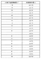
図9に、温度変化に対する波長誤検知量Δλのテーブルを示す。また、テーブル内の各波長誤検知量Δλの値は、予め実験で得られた代表値をメモリ205に記憶しておくものとする。実施例2では、実施例1と同様の動作でLED光源の素子温度変動量ΔT’を検出し、得られたLED素子温度変動量ΔT’に対応する波長誤検知量Δλをテーブルから読み出し、補正動作を行う。
FIG. 9 shows a table of erroneous wavelength detection amounts Δλ with respect to temperature changes. Further, as the value of each wavelength erroneous detection amount Δλ in the table, it is assumed that a representative value obtained by an experiment is stored in the
[処理フロー]
図10に、本実施例の測定動作の概略を示す。測定シーケンスを開始すると、S1001にてエンジン制御部312は、シャッタ開閉機構212に、シャッタ214を開くように指示する。S1002にてエンジン制御部312は、カラーセンサ制御部302に白色基準板210の検知を指示する。カラーセンサ制御部302は、白色基準板210の検知時において、LED光源201を発光させる。更に、カラーセンサ制御部302は、ラインセンサ203の出力値が所定値となるように、LED光源201の駆動電流値を制御するLEDドライバ221に電流値を設定し、白色基準板210からの反射光量W(λ)を取得する。S1003にてエンジン制御部312は、取得した反射光量W(λ)に基づいてピーク画素の移動量ΔDを算出する。本工程は、実施例1にて述べた図7Bの処理と同様である。
[Processing flow]
FIG. 10 shows an outline of the measurement operation of this example. When the measurement sequence is started, the
S1004にてカラーセンサ制御部302は、カラーセンサ200内部のサーミスタ220から取得した周囲温度TとLED光源201の駆動電流Iとを用いて式(4)の演算により、LED光源の素子温度T’を算出する。S1005にてカラーセンサ制御部302は、メモリ205から、LED光源の素子温度T’に対応する波長誤検知量Δλを読み出す。S1006にてエンジン制御部312は、用紙搬送ローラ311を動作させ、測定対象(チャート)を搬送し、各パッチの測定値P(λ)を検出する。S1007にてカラーセンサ制御部302は、得られたW(λ)、P(λ)、波長誤検知量Δλを用いて式(2)から、分光反射率R(λ)を算出する。S1008にてエンジン制御部312は、シャッタ開閉機構212に、シャッタ214を閉じるように指示する。その後、一連の測定シーケンスを終了する。
In S1004, the color
以上により、実施例1同様に波長とラインセンサの位置関係のずれを補正可能であり、温度変化に対して色の測定精度を維持することが可能となる。更に、実施例1と比べ、テーブルを用いることでより簡易な動作で補正が可能になる。 As described above, the positional relationship between the wavelength and the line sensor can be corrected similarly to the first embodiment, and the color measurement accuracy can be maintained with respect to the temperature change. Further, as compared with the first embodiment, correction can be performed with a simpler operation by using a table.
Claims (9)
前記測定用画像を前記シートに定着させる定着手段と、
前記定着手段により前記測定用画像が定着された前記シートを搬送する搬送手段と、
光を発する発光部と、回折格子と、複数の画素を有し、前記回折格子により分光された光を受光する受光部とを備え、基準部材からの反射光を前記受光部が受光した結果に基づいて前記発光部の光量が所定光量となるように前記発光部を駆動する電力を制御する調整制御を実行する測定手段と、
前記搬送手段により搬送された前記シート上の前記測定用画像に光を照射するために前記発光部を発光させ、前記回折格子によって分光された前記測定用画像からの反射光を前記受光部に受光させ、前記複数の画素と波長との対応関係に基づいて前記受光部による前記測定用画像からの反射光の受光結果から前記測定用画像の測定結果に関するデータを生成する生成手段と、
前記発光部を発光させ、前記回折格子によって分光された前記基準部材からの反射光を前記受光部に受光させ、前記基準部材からの反射光の受光結果に基づいて、前記受光部によって受光される光の波長の第1シフト量を決定する第1決定手段と、
前記測定手段の周囲の温度を検知する検知手段と、
前記検知手段により検知された前記温度と前記発光部の前記電力とに基づいて、前記受光部によって受光される光の波長の第2シフト量を決定する第2決定手段と、
前記複数の画素と波長との前記対応関係を、前記第1シフト量と前記第2シフト量とに基づいて調整する調整手段と
を有することを特徴とする画像形成装置。 Image forming means for forming a measurement image on a sheet;
Fixing means for fixing the measurement image to the sheet;
A conveying unit configured to convey the sheet on which the measurement image is fixed by the fixing unit;
A light-emitting unit that emits light, a diffraction grating, and a light-receiving unit that has a plurality of pixels and receives light dispersed by the diffraction grating, and the light-receiving unit receives reflected light from a reference member Measurement means for performing adjustment control for controlling the power for driving the light emitting unit so that the light amount of the light emitting unit becomes a predetermined light amount based on ;
The light emitting unit emits light to irradiate the measurement image on the sheet conveyed by the conveying unit, and the reflected light from the measurement image dispersed by the diffraction grating is received by the light receiving unit. Generating means for generating data related to the measurement result of the measurement image from the light reception result of the reflected light from the measurement image by the light receiving unit based on the correspondence relationship between the plurality of pixels and wavelengths;
Wherein the light emitting portion to emit light, the light reflected from the reference member which is spectrally separated by the diffraction grating is received by the photodetection unit, based on the light reception result of the reflected light from the reference member, and is received by said light receiving portion First determining means for determining a first shift amount of the wavelength of light;
Detecting means for detecting the ambient temperature of the measuring means;
Second determining means for determining a second shift amount of the wavelength of light received by the light receiving part based on the temperature detected by the detecting means and the power of the light emitting part ;
An image forming apparatus, comprising: an adjusting unit that adjusts the correspondence relationship between the plurality of pixels and the wavelengths based on the first shift amount and the second shift amount.
前記第1決定手段は、前記基準部材からの反射光の受光結果において受光強度が最大値となる画素と、前記記憶部に記憶された前記基準画素とに基づいて、前記第1シフト量を決定することを特徴とする請求項2に記載の画像形成装置。 The first determining unit includes a storage unit that stores a reference pixel having a maximum light reception intensity in a light reception result of reflected light from the reference member,
The first determination unit determines the first shift amount based on a pixel having a maximum light reception intensity in a light reception result of reflected light from the reference member and the reference pixel stored in the storage unit. The image forming apparatus according to claim 2.
前記第2決定手段は、前記検知手段により検知された前記発光部の温度と、前記取得部により取得された前記駆動電流とに基づいて、前記第2シフト量を決定することを特徴とする請求項1乃至4のいずれか一項に記載の画像形成装置。 The second determination unit includes an acquisition unit that acquires a drive current of the light emitting unit as the power of the light emitting unit,
The second determining unit determines the second shift amount based on the temperature of the light emitting unit detected by the detecting unit and the drive current acquired by the acquiring unit. Item 5. The image forming apparatus according to any one of Items 1 to 4.
前記検知手段は、前記電圧検出部により検出された前記端子間電圧に基づいて、前記発光部の温度を検知することを特徴とする請求項1乃至5のいずれか一項に記載の画像形成装置。 The detection means includes a voltage detection unit that detects a voltage between terminals of the light emitting unit,
The image forming apparatus according to claim 1, wherein the detection unit detects a temperature of the light emitting unit based on the voltage between the terminals detected by the voltage detection unit. .
Priority Applications (4)
| Application Number | Priority Date | Filing Date | Title |
|---|---|---|---|
| JP2013031426A JP6257148B2 (en) | 2013-02-20 | 2013-02-20 | Image forming apparatus |
| PCT/JP2014/052597 WO2014129306A1 (en) | 2013-02-20 | 2014-01-29 | Measurement apparatus |
| US14/655,295 US10078012B2 (en) | 2013-02-20 | 2014-01-29 | Measurement apparatus with adjustment for spectral shift |
| CN201480009066.5A CN105074403B (en) | 2013-02-20 | 2014-01-29 | Measurement apparatus |
Applications Claiming Priority (1)
| Application Number | Priority Date | Filing Date | Title |
|---|---|---|---|
| JP2013031426A JP6257148B2 (en) | 2013-02-20 | 2013-02-20 | Image forming apparatus |
Related Child Applications (1)
| Application Number | Title | Priority Date | Filing Date |
|---|---|---|---|
| JP2017233649A Division JP6450444B2 (en) | 2017-12-05 | 2017-12-05 | Measuring apparatus and image forming apparatus |
Publications (2)
| Publication Number | Publication Date |
|---|---|
| JP2014160986A JP2014160986A (en) | 2014-09-04 |
| JP6257148B2 true JP6257148B2 (en) | 2018-01-10 |
Family
ID=51391103
Family Applications (1)
| Application Number | Title | Priority Date | Filing Date |
|---|---|---|---|
| JP2013031426A Expired - Fee Related JP6257148B2 (en) | 2013-02-20 | 2013-02-20 | Image forming apparatus |
Country Status (4)
| Country | Link |
|---|---|
| US (1) | US10078012B2 (en) |
| JP (1) | JP6257148B2 (en) |
| CN (1) | CN105074403B (en) |
| WO (1) | WO2014129306A1 (en) |
Families Citing this family (6)
| Publication number | Priority date | Publication date | Assignee | Title |
|---|---|---|---|---|
| JP6691683B2 (en) * | 2016-02-25 | 2020-05-13 | 株式会社リコー | Image density detecting apparatus, image forming apparatus, image density detecting method and image forming method |
| JP6776650B2 (en) * | 2016-06-23 | 2020-10-28 | 富士ゼロックス株式会社 | Printhead and image forming equipment |
| JP7081286B2 (en) * | 2018-04-27 | 2022-06-07 | 株式会社リコー | Readers, image forming devices, information detection methods, and programs |
| JP6973275B2 (en) * | 2018-04-27 | 2021-11-24 | 京セラドキュメントソリューションズ株式会社 | Image forming device and display device |
| JP2021162744A (en) * | 2020-04-01 | 2021-10-11 | キヤノン株式会社 | Image forming apparatus |
| TW202145839A (en) * | 2020-05-14 | 2021-12-01 | 日商東京威力科創股份有限公司 | Calibration method and calibration system |
Family Cites Families (42)
| Publication number | Priority date | Publication date | Assignee | Title |
|---|---|---|---|---|
| US3711708A (en) * | 1971-02-25 | 1973-01-16 | Optical Coating Laboratory Inc | Rapid scan identifier for use in infrared absorption spectroscopy |
| JPS6095545U (en) * | 1983-12-07 | 1985-06-29 | 東亜電波工業株式会社 | Absorption photometer |
| US4986665A (en) | 1987-08-06 | 1991-01-22 | Minolta Camera Kabushiki Kaisha | Optical density detector |
| JPH01287444A (en) * | 1988-05-13 | 1989-11-20 | Minolta Camera Co Ltd | Optical densitometer |
| US5347475A (en) * | 1991-09-20 | 1994-09-13 | Amoco Corporation | Method for transferring spectral information among spectrometers |
| US5754283A (en) | 1994-10-26 | 1998-05-19 | Byk-Gardner Usa, Division Of Atlana | Color measuring device having interchangeable optical geometries |
| US5502782A (en) * | 1995-01-09 | 1996-03-26 | Optelecom, Inc. | Focused acoustic wave fiber optic reflection modulator |
| US6485625B1 (en) * | 1995-05-09 | 2002-11-26 | Curagen Corporation | Apparatus and method for the generation, separation, detection, and recognition of biopolymer fragments |
| JP3222052B2 (en) * | 1996-01-11 | 2001-10-22 | 株式会社東芝 | Optical scanning device |
| US6783705B1 (en) * | 1997-04-11 | 2004-08-31 | Waters Investments Limited | Calibration medium for wavelength calibration of U.V. absorbance detectors and methods for calibration |
| JP4015249B2 (en) * | 1997-12-26 | 2007-11-28 | 株式会社東芝 | Multi-beam exposure system |
| JP3441994B2 (en) * | 1999-02-24 | 2003-09-02 | キヤノン株式会社 | Image processing apparatus and control method thereof |
| US6431446B1 (en) * | 1999-07-28 | 2002-08-13 | Ncr Corporation | Produce recognition system and method |
| JP3679686B2 (en) * | 2000-06-08 | 2005-08-03 | キヤノン株式会社 | Image reading apparatus and method, and document protection sheet |
| US6750972B2 (en) * | 2000-11-17 | 2004-06-15 | Cymer, Inc. | Gas discharge ultraviolet wavemeter with enhanced illumination |
| US20050068520A1 (en) | 2001-02-02 | 2005-03-31 | Beimers Daniel J. | Handheld color measurement instrument |
| JP2002243635A (en) * | 2001-02-19 | 2002-08-28 | Fuji Xerox Co Ltd | Reflection factor measuring instrument |
| JP2004086013A (en) * | 2002-08-28 | 2004-03-18 | Canon Inc | Method and device for correcting shading of sensor and color image forming apparatus |
| JP3620798B2 (en) * | 2003-06-27 | 2005-02-16 | 株式会社アステム | Nondestructive spectrometer |
| JP3702889B2 (en) * | 2003-08-21 | 2005-10-05 | コニカミノルタセンシング株式会社 | Spectrometer and spectroscopic device correction method |
| DE102005002267B4 (en) * | 2005-01-18 | 2017-02-09 | Leica Microsystems Cms Gmbh | Method for wavelength calibration of an optical measuring system |
| US7271910B2 (en) * | 2005-03-30 | 2007-09-18 | Xerox Corporation | Systems and methods for compensating for temperature induced spectral emission variations in LED based color parameter measuring devices |
| TW200729102A (en) | 2005-11-30 | 2007-08-01 | Max Co Ltd | Peel-off paper-attached label and label printer |
| JP2007144954A (en) | 2005-11-30 | 2007-06-14 | Max Co Ltd | Label with release paper and label printer |
| US7583378B2 (en) * | 2006-02-23 | 2009-09-01 | Itt Manufacturing Enterprises, Inc. | Spectrograph calibration using known light source and Raman scattering |
| US8144320B2 (en) * | 2006-11-22 | 2012-03-27 | Optopo, Inc. | Method and apparatus for reconstructing optical spectra in a static multimode multiplex spectrometer |
| JP4876943B2 (en) | 2007-01-31 | 2012-02-15 | コニカミノルタセンシング株式会社 | Wavelength change correction system and wavelength change correction method |
| CA2894945C (en) * | 2007-04-04 | 2018-01-09 | Netbio, Inc. | Methods for rapid multiplexed amplification of target nucleic acids |
| JP5109482B2 (en) * | 2007-05-31 | 2012-12-26 | コニカミノルタオプティクス株式会社 | Reflection characteristic measuring apparatus and calibration method for reflection characteristic measuring apparatus |
| US7547869B2 (en) * | 2007-11-21 | 2009-06-16 | Avago Technologies Ecbu Ip (Singapore) Pte. Ltd. | Illumination system calibration and operation having a calibration matrix calculation based on a shift in color space |
| JP5195905B2 (en) | 2008-03-28 | 2013-05-15 | コニカミノルタオプティクス株式会社 | Spectral characteristics measurement system |
| JP5104714B2 (en) * | 2008-10-20 | 2012-12-19 | コニカミノルタオプティクス株式会社 | Reflection characteristic measuring apparatus and reflection characteristic measuring method |
| US8107073B2 (en) * | 2009-02-12 | 2012-01-31 | Tokyo Electron Limited | Diffraction order sorting filter for optical metrology |
| JP2010210456A (en) * | 2009-03-11 | 2010-09-24 | Ricoh Co Ltd | Optical characteristics measuring apparatus, spectrophotometric colorimetry apparatus, and image forming apparatus |
| JP5440110B2 (en) * | 2009-03-30 | 2014-03-12 | 株式会社リコー | Spectral characteristic acquisition apparatus, spectral characteristic acquisition method, image evaluation apparatus, and image forming apparatus |
| JP2012098152A (en) | 2010-11-02 | 2012-05-24 | Fujifilm Corp | Print color prediction device, print color prediction method and program |
| JP5744655B2 (en) * | 2011-07-15 | 2015-07-08 | キヤノン株式会社 | Spectral color sensor and image forming apparatus |
| JP5947502B2 (en) * | 2011-08-11 | 2016-07-06 | キヤノン株式会社 | Spectral colorimeter and image forming apparatus |
| TWI609172B (en) * | 2012-11-13 | 2017-12-21 | 唯亞威方案公司 | Portable spectrometer |
| US8849080B1 (en) * | 2013-01-14 | 2014-09-30 | The United States Of America As Represented By The Secretary Of The Navy | Monolithically integrated fiber optic coupler |
| US9546904B2 (en) * | 2013-03-15 | 2017-01-17 | P & P Optica Inc. | Apparatus and method for optimizing data capture and data correction for spectroscopic analysis |
| JP6624842B2 (en) * | 2015-08-07 | 2019-12-25 | キヤノン株式会社 | Image forming device |
-
2013
- 2013-02-20 JP JP2013031426A patent/JP6257148B2/en not_active Expired - Fee Related
-
2014
- 2014-01-29 US US14/655,295 patent/US10078012B2/en active Active
- 2014-01-29 CN CN201480009066.5A patent/CN105074403B/en not_active Expired - Fee Related
- 2014-01-29 WO PCT/JP2014/052597 patent/WO2014129306A1/en active Application Filing
Also Published As
| Publication number | Publication date |
|---|---|
| WO2014129306A1 (en) | 2014-08-28 |
| CN105074403B (en) | 2017-05-17 |
| CN105074403A (en) | 2015-11-18 |
| US10078012B2 (en) | 2018-09-18 |
| JP2014160986A (en) | 2014-09-04 |
| US20150346028A1 (en) | 2015-12-03 |
Similar Documents
| Publication | Publication Date | Title |
|---|---|---|
| US9057646B2 (en) | Image forming apparatus for measuring a color of a measurement image | |
| RU2529776C2 (en) | Device of image generation | |
| JP5991775B2 (en) | Measuring apparatus and image forming apparatus | |
| JP6257148B2 (en) | Image forming apparatus | |
| US10212314B2 (en) | Image forming apparatus with color calibration by measurement image | |
| US8908243B2 (en) | Image forming apparatus for measuring fixed image | |
| US9020400B2 (en) | Image forming apparatus for forming a measurement image | |
| JP6222935B2 (en) | Image forming apparatus | |
| JP5905018B2 (en) | Image forming apparatus | |
| JP5904755B2 (en) | Image forming apparatus | |
| US20140050496A1 (en) | Image forming apparatus for forming a measurement image | |
| US9290006B2 (en) | Image forming apparatus for measuring the color of a measurement image | |
| JP5600477B2 (en) | Printing apparatus, measuring apparatus, and control method thereof | |
| US8948634B2 (en) | Image forming apparatus | |
| US9921516B2 (en) | Image forming apparatus and image forming method | |
| JP6450444B2 (en) | Measuring apparatus and image forming apparatus | |
| JP2018205461A (en) | Image formation apparatus | |
| JP2013080181A (en) | Image forming apparatus | |
| JP2005175585A (en) | Image forming apparatus | |
| JP2014160988A (en) | Image forming apparatus | |
| JP2017151138A (en) | Color measuring device, and image forming apparatus | |
| JP2014165802A (en) | Image forming apparatus |
Legal Events
| Date | Code | Title | Description |
|---|---|---|---|
| A621 | Written request for application examination |
Free format text: JAPANESE INTERMEDIATE CODE: A621 Effective date: 20160219 |
|
| A131 | Notification of reasons for refusal |
Free format text: JAPANESE INTERMEDIATE CODE: A131 Effective date: 20160930 |
|
| A521 | Request for written amendment filed |
Free format text: JAPANESE INTERMEDIATE CODE: A523 Effective date: 20161129 |
|
| A131 | Notification of reasons for refusal |
Free format text: JAPANESE INTERMEDIATE CODE: A131 Effective date: 20170417 |
|
| A521 | Request for written amendment filed |
Free format text: JAPANESE INTERMEDIATE CODE: A523 Effective date: 20170616 |
|
| TRDD | Decision of grant or rejection written | ||
| A01 | Written decision to grant a patent or to grant a registration (utility model) |
Free format text: JAPANESE INTERMEDIATE CODE: A01 Effective date: 20171106 |
|
| A61 | First payment of annual fees (during grant procedure) |
Free format text: JAPANESE INTERMEDIATE CODE: A61 Effective date: 20171205 |
|
| R151 | Written notification of patent or utility model registration |
Ref document number: 6257148 Country of ref document: JP Free format text: JAPANESE INTERMEDIATE CODE: R151 |
|
| LAPS | Cancellation because of no payment of annual fees |