JP6256788B2 - Cooling device and image forming apparatus - Google Patents

Cooling device and image forming apparatus Download PDF

Info

Publication number
JP6256788B2
JP6256788B2 JP2012244842A JP2012244842A JP6256788B2 JP 6256788 B2 JP6256788 B2 JP 6256788B2 JP 2012244842 A JP2012244842 A JP 2012244842A JP 2012244842 A JP2012244842 A JP 2012244842A JP 6256788 B2 JP6256788 B2 JP 6256788B2
Authority
JP
Japan
Prior art keywords
flow path
cooling
recording material
folded
cooling member
Prior art date
Legal status (The legal status is an assumption and is not a legal conclusion. Google has not performed a legal analysis and makes no representation as to the accuracy of the status listed.)
Active
Application number
JP2012244842A
Other languages
Japanese (ja)
Other versions
JP2013228666A (en
JP2013228666A5 (en
Inventor
圭介 池田
圭介 池田
平澤 友康
友康 平澤
政範 斉藤
政範 斉藤
Current Assignee (The listed assignees may be inaccurate. Google has not performed a legal analysis and makes no representation or warranty as to the accuracy of the list.)
Ricoh Co Ltd
Original Assignee
Ricoh Co Ltd
Priority date (The priority date is an assumption and is not a legal conclusion. Google has not performed a legal analysis and makes no representation as to the accuracy of the date listed.)
Filing date
Publication date
Application filed by Ricoh Co Ltd filed Critical Ricoh Co Ltd
Priority to JP2012244842A priority Critical patent/JP6256788B2/en
Priority to US13/850,506 priority patent/US9063482B2/en
Priority to EP13161424.0A priority patent/EP2645188B1/en
Publication of JP2013228666A publication Critical patent/JP2013228666A/en
Publication of JP2013228666A5 publication Critical patent/JP2013228666A5/ja
Application granted granted Critical
Publication of JP6256788B2 publication Critical patent/JP6256788B2/en
Active legal-status Critical Current
Anticipated expiration legal-status Critical

Links

Images

Classifications

    • GPHYSICS
    • G03PHOTOGRAPHY; CINEMATOGRAPHY; ANALOGOUS TECHNIQUES USING WAVES OTHER THAN OPTICAL WAVES; ELECTROGRAPHY; HOLOGRAPHY
    • G03GELECTROGRAPHY; ELECTROPHOTOGRAPHY; MAGNETOGRAPHY
    • G03G15/00Apparatus for electrographic processes using a charge pattern
    • G03G15/20Apparatus for electrographic processes using a charge pattern for fixing, e.g. by using heat
    • G03G15/2003Apparatus for electrographic processes using a charge pattern for fixing, e.g. by using heat using heat
    • G03G15/2014Apparatus for electrographic processes using a charge pattern for fixing, e.g. by using heat using heat using contact heat
    • G03G15/2039Apparatus for electrographic processes using a charge pattern for fixing, e.g. by using heat using heat using contact heat with means for controlling the fixing temperature
    • GPHYSICS
    • G03PHOTOGRAPHY; CINEMATOGRAPHY; ANALOGOUS TECHNIQUES USING WAVES OTHER THAN OPTICAL WAVES; ELECTROGRAPHY; HOLOGRAPHY
    • G03GELECTROGRAPHY; ELECTROPHOTOGRAPHY; MAGNETOGRAPHY
    • G03G21/00Arrangements not provided for by groups G03G13/00 - G03G19/00, e.g. cleaning, elimination of residual charge
    • G03G21/20Humidity or temperature control also ozone evacuation; Internal apparatus environment control
    • G03G21/206Conducting air through the machine, e.g. for cooling, filtering, removing gases like ozone

Description

本発明は、プリンタ、ファクシミリ、複写機などの画像形成装置に用いられる冷却装置、及びこの冷却装置を備えた画像形成装置に関するものである。   The present invention relates to a cooling device used in an image forming apparatus such as a printer, a facsimile machine, and a copying machine, and an image forming apparatus provided with the cooling device.

画像形成装置として、電子写真技術を用いて記録材上にトナー画像を形成し、定着装置によって加熱・加圧を行うことで記録材上に転写されたトナーを定着させるものが知られている。定着後の記録材が熱を持ったまま排紙トレイにスタックされていくと積み重なった記録材の束内にこもった熱によってトナーが軟化することがある。排紙トレイにスタックされた記録材上のトナー画像を形成するトナーが軟化した状態で、さらに記録材が重なると、記録材の束の自重による圧力が生じて、軟化したトナーによって記録材間が貼りついてしまうブロッキングという現象が生じてしまう場合がある。ブロッキングが生じた記録材同士を無理に剥がそうとするとトナー像が壊れてしまう。   2. Description of the Related Art As an image forming apparatus, there is known an image forming apparatus that forms a toner image on a recording material using an electrophotographic technique, and fixes the toner transferred onto the recording material by heating and pressing with a fixing device. When the recording material after fixing is stacked on the paper discharge tray with heat, the toner may be softened by the heat accumulated in the stack of stacked recording materials. When the toner that forms a toner image on the recording material stacked on the paper discharge tray is softened and the recording materials are further overlapped, pressure is generated due to the weight of the recording material bundle, and the softened toner causes a gap between the recording materials. There is a case where the phenomenon of blocking that sticks occurs. If the recording materials with blocking are forcibly removed, the toner image will be broken.

このブロッキングと呼ばれる現象を抑制するためには、加熱定着後の記録材を十分に冷却するための装置が必要である。記録材を冷却する手段として、内部を冷媒である冷却液が通過する液冷方式の冷却部材を直接又は間接的に搬送されている記録材に接触させて、記録材からの熱を吸熱する装置が既に知られている。
例えば、特許文献1には、無端ベルトを介して冷却面を間接的に搬送されている記録材に接触させて記録材を冷却する、次のような冷却液の通過流路を内部に有する冷却部材を備えた冷却装置が記載されている。記録材搬送方向に交差するように並列して設けられた複数の流路部と、隣接する冷却液搬送方向上流側の流路部から下流側の流路部に、冷却部材の端部近傍で流れる向きを変えて冷却液を導く折り返し流路部とからなる通過流路を冷却部材の内部に有したものである。
In order to suppress this phenomenon called blocking, an apparatus for sufficiently cooling the recording material after heating and fixing is necessary. As a means for cooling the recording material, a device that absorbs heat from the recording material by bringing a liquid-cooling type cooling member through which the coolant, which is a refrigerant, passes, into contact with the recording material being conveyed directly or indirectly Is already known.
For example, Japanese Patent Laid-Open No. 2004-228688 discloses a cooling liquid having a cooling liquid passage, which cools the recording material by bringing the cooling surface into contact with the recording material conveyed indirectly through an endless belt. A cooling device with a member is described. In the vicinity of the end of the cooling member, a plurality of flow path portions provided in parallel so as to intersect the recording material conveyance direction, and an adjacent flow path portion on the upstream side from the upstream flow path direction in the cooling liquid conveyance direction. The cooling member has a passage passage formed of a folded passage portion that changes the flow direction and guides the coolant.

しかし、特許文献1に記載の冷却装置のように、冷却部材の内部に通過流路の折り返し流路部を設けた構成では、次のような不具合が生じる場合があった。冷却液の通過流路に設ける折り返し流路部の数が多くなるほど、冷却部材の冷却面では記録材搬送方向に垂直な方向における端部(折り返し流路部の近傍)で、他の部分に比べ冷却効果が強くなる。これは、主に、冷却部材の記録材搬送方向に垂直な方向の単位幅当たりの、冷却液が通過流路の内周面に接触して熱交換を行う面積が、複数の流路部を設けた範囲に比べ、折り返し流路部で広くなってしまうためである。そして、冷却される記録材では、記録材搬送方向に垂直な方向の端部と中央部で光沢等の画像品質にムラが生じてしまうという問題である。   However, in the configuration in which the folded flow path portion of the passage flow path is provided inside the cooling member as in the cooling device described in Patent Document 1, the following problems may occur. As the number of folded flow path portions provided in the coolant flow path increases, the cooling surface of the cooling member has an end portion in the direction perpendicular to the recording material conveyance direction (near the folded flow path portion) as compared with other portions. Increases cooling effect. This is mainly because the area of the cooling member per unit width in the direction perpendicular to the recording material transport direction is in contact with the inner peripheral surface of the passage flow path to exchange heat, and the plurality of flow path portions. This is because the folded channel portion becomes wider than the provided range. In the recording material to be cooled, there is a problem that unevenness in image quality such as gloss occurs at the end and the center in the direction perpendicular to the recording material conveyance direction.

本発明は以上の問題点に鑑みなされたものであり、その目的は、次のような冷却装置を提供することである。記録材搬送方向に交差するように設けられた複数の流路部と、折り返し流路部とからなる冷却液の通過流路を有する冷却部材を備えた冷却装置において、記録材搬送方向に垂直な方向の冷却効果の偏りを、少なくとも画像形成領域内で抑制できる冷却装置である。   The present invention has been made in view of the above problems, and an object thereof is to provide the following cooling device. In a cooling device including a cooling member having a cooling liquid passage including a plurality of flow path portions provided to intersect the recording material transport direction and a folded flow path portion, the cooling device is perpendicular to the recording material transport direction. This is a cooling device capable of suppressing the deviation of the cooling effect in the direction at least in the image forming area.

上記目的を達成するために、請求項1に記載の冷却装置は、冷却液の通過流路を有する冷却部材の冷却面を直接又は間接的に、搬送される記録材に接触させて該記録材を冷却し、前記冷却部材の内部に設けられた前記通過流路が、前記記録材の搬送方向に交差し、且つ前記冷却面、及び搬送される該記録材に対向するように設けられた複数の流路部と、隣接する冷却液搬送方向上流側の流路部から下流側の流路部に、流れる向きを変えて前記冷却液を導き、且つ前記冷却面に対向するように設けられた折り返し流路部とを具備するものである冷却装置において、前記通過流路を前記記録材の搬送面に投影した場合の前記折り返し流路部の外郭線を、記録材搬送方向に平行な辺を有した矩形状の形状にし、前記冷却部材における前記流路部長手方向の全域のうち、搬送可能な最大サイズの前記記録材である最大記録材における画像形成領域の外側となる領域に、前記折り返し流路部を設け、且つ、前記搬送面に沿って搬送される前記記録材の中心が通る前記搬送面上の直線である記録材中心線から離れた側の前記折り返し流路部の外郭線の前記記録材搬送方向に平行な辺である外側辺を、前記記録材中心線から離れた側の一辺とする仮想正方形に内接する仮想円の中心位置が、前記流路部の外郭線が垂直に接続する前記記録材中心線に近い側の前記折り返し流路部の外郭線の前記記録材搬送方向に平行な辺である内側辺上、又は該内側辺より前記記録材中心線から離れている場合に、前記折り返し流路部の外郭線の前記記録材搬送方向に平行な内側辺を、前記冷却部材における前記流路部長手方向の全域のうち、前記最大記録材の画像形成領域の外側となる領域に位置させるように、前記折り返し流路部を配設したことを特徴とするものである。
本発明は、冷却部材の冷却面における記録材の画像形成領域外に、他の部分に比べ冷却効果が強くなる折り返し流路部を設けるので、記録材搬送方向に垂直な方向の冷却効果を、画像形成領域内に折り返し流路部を設ける構成に比べて均一化することができる。
In order to achieve the above object, the cooling device according to claim 1 is configured such that a cooling surface of a cooling member having a flow path for cooling liquid is directly or indirectly brought into contact with a recording material to be conveyed. A plurality of passage channels provided in the cooling member so as to cross the recording material conveyance direction and to face the cooling surface and the recording material to be conveyed. The flow channel portion and the adjacent flow channel portion on the upstream side in the cooling liquid conveyance direction from the upstream flow channel portion to the downstream flow channel portion are provided so as to guide the cooling liquid in different directions and to face the cooling surface. In the cooling device having the folded flow path portion, the outer line of the folded flow path portion when the passing flow path is projected onto the recording material transport surface is defined by a side parallel to the recording material transport direction. and a rectangular shape having the channel manager hand in the cooling member Of the entire area of the direction, a region where the outer side of the image forming region of the maximum recording medium is the recording medium of the maximum size that can be conveyed, the turned-back channel portion is provided, and is conveyed along the conveying surface An outer side that is a side parallel to the recording material conveyance direction of the outer line of the folded flow path portion on the side away from the recording material center line, which is a straight line on the conveyance surface through which the center of the recording material passes, The center position of a virtual circle inscribed in a virtual square that is one side away from the material center line is a position of the folded flow path portion on the side close to the recording material center line where the outline of the flow path portion is vertically connected. When the outer line is on the inner side which is a side parallel to the recording material conveyance direction, or is away from the recording material center line from the inner side, the outer line of the folded flow path portion extends in the recording material conveyance direction. Parallel inner sides are aligned with the flow in the cooling member. Of the entire area of the longitudinal direction of the so as to lie outside the a region of the image forming region of the maximum recording medium, it is characterized in that it has provided the turned-back channel portion.
In the present invention, since the folded flow path portion is provided outside the image forming area of the recording material on the cooling surface of the cooling member so that the cooling effect is stronger than other portions, the cooling effect in the direction perpendicular to the recording material conveyance direction is Compared to the configuration in which the folded flow path portion is provided in the image forming region, it can be made uniform.

本発明によれば、記録材搬送方向に垂直な方向の冷却効果の偏りを、少なくとも画像形成領域内で抑制できる。   According to the present invention, the deviation of the cooling effect in the direction perpendicular to the recording material conveyance direction can be suppressed at least in the image forming area.

一実施形態に係る画像形成装置の概略構成図。1 is a schematic configuration diagram of an image forming apparatus according to an embodiment. 実施例1に係る冷却装置の構成説明図。1 is a configuration explanatory diagram of a cooling device according to Embodiment 1. FIG. 実施例1に係る冷却装置に設けた冷却部材の説明図。FIG. 3 is an explanatory diagram of a cooling member provided in the cooling device according to the first embodiment. 用紙を冷却する際の冷却部材の温度分布についての説明図。Explanatory drawing about the temperature distribution of the cooling member at the time of cooling paper. 折り返し流路部を用紙通過領域内に設けた構成、及び用紙通過領域外に設けた構成の、冷却後の用紙搬送方向に垂直な方向の温度分布を示したグラフ。6 is a graph showing a temperature distribution in a direction perpendicular to a paper transport direction after cooling in a configuration in which a folded flow path portion is provided in the paper passage region and a configuration in which the return flow path portion is provided outside the paper passage region. 実施例1に係る冷却部材に冷却液の通過流路の設け方の一例の説明図。FIG. 3 is an explanatory diagram of an example of a method for providing a coolant passage in the cooling member according to the first embodiment. 実施例1に係る冷却部材の折り返し流路部の切削深さについての説明図。FIG. 4 is an explanatory diagram about the cutting depth of the folded flow path portion of the cooling member according to the first embodiment. 実施例1に係る冷却部材の折り返し流路部の削切深さと、冷却液の通過流路における圧力損失の関係を示すグラフ。6 is a graph showing the relationship between the cutting depth of the folded flow path portion of the cooling member according to the first embodiment and the pressure loss in the flow path of the coolant. 実施例2に係る冷却装置に設けた冷却部材の説明図。Explanatory drawing of the cooling member provided in the cooling device which concerns on Example 2. FIG. 実施例3に係る冷却装置の構成説明図。FIG. 9 is a configuration explanatory diagram of a cooling device according to a third embodiment. 実施例3に係る冷却装置に設けた冷却部材の説明図。Explanatory drawing of the cooling member provided in the cooling device which concerns on Example 3. FIG. 実施例4に係る冷却装置に設けた冷却部材の説明図。Explanatory drawing of the cooling member provided in the cooling device which concerns on Example 4. FIG. 実施例4に係る冷却部材の製作方法の説明図。Explanatory drawing of the manufacturing method of the cooling member which concerns on Example 4. FIG. 実施例5に係る冷却装置に設けた冷却部材の説明図。Explanatory drawing of the cooling member provided in the cooling device which concerns on Example 5. FIG. 実施例6に係る冷却装置に設けた冷却部材の例の説明図。FIG. 10 is an explanatory diagram of an example of a cooling member provided in a cooling device according to a sixth embodiment. 実施例6に係る冷却部材に矩形状の折り返し流路部を設け、折り返し流路部の内側内壁面の位置を画像形成領域外とした例の説明図。FIG. 10 is an explanatory diagram of an example in which a rectangular folded channel portion is provided in the cooling member according to the sixth embodiment, and the position of the inner inner wall surface of the folded channel portion is outside the image forming region. 実施例6に係る冷却部材に矩形状の折り返し流路部を設け、折り返し流路部における仮想円の中心位置を画像形成領域外とした例の説明図。FIG. 10 is an explanatory diagram of an example in which a rectangular folded channel portion is provided in the cooling member according to the sixth embodiment, and the center position of a virtual circle in the folded channel portion is outside the image forming region. 実施例7に係る冷却部材に円弧状の折り返し流路部を設けた例の説明図。FIG. 10 is an explanatory diagram of an example in which an arcuate folded channel portion is provided in the cooling member according to the seventh embodiment. 実施例7に係る冷却部材に曲線部を有した折り返し流路部を設けた例の説明図。Explanatory drawing of the example which provided the folding | returning flow-path part which has a curved part in the cooling member which concerns on Example 7. FIG. 実施例7に係る冷却部材に曲線部を有した折り返し流路部を設けた別例の説明図。FIG. 10 is an explanatory diagram of another example in which a cooling flow path portion having a curved portion is provided in the cooling member according to the seventh embodiment. 実施例8に係る冷却部材の折り返し流路部の説明図。FIG. 10 is an explanatory diagram of a folded channel portion of a cooling member according to an eighth embodiment.

以下、本発明を画像形成装置に備えた冷却装置に適用した一実施形態について、複数の実施例を挙げ、図を用いて説明する。まず、各実施例に共通する本実施形態の画像形成装置であるプリンタ300の概略について説明する。図1は、本実施形態に係る画像形成装置であるプリンタ300の概略構成図である。   Hereinafter, an embodiment in which the present invention is applied to a cooling device provided in an image forming apparatus will be described with reference to the drawings with a plurality of examples. First, an outline of a printer 300 that is an image forming apparatus according to the present embodiment common to the respective examples will be described. FIG. 1 is a schematic configuration diagram of a printer 300 that is an image forming apparatus according to the present embodiment.

図1に示すように、本実施形態のプリンタ300は、複数のローラ(第1張架ローラ22、第2張架ローラ23、第3張架ローラ24等)によって中間転写媒体としての中間転写ベルト21を張架している。そして、中間転写ベルト21は、複数のローラのうちの一つが回転駆動することにより図中矢印a方向に回転する構成である。また、プリンタ300は、中間転写ベルト21のまわりに画像形成用のプロセス手段を配置している。ここで、符号の後に付されたY,C,M,Bkという添字は、イエロー,シアン,マゼンタ,ブラック用の仕様であることを示している。   As shown in FIG. 1, the printer 300 of this embodiment includes an intermediate transfer belt as an intermediate transfer medium by a plurality of rollers (a first stretching roller 22, a second stretching roller 23, a third stretching roller 24, and the like). 21 is stretched. The intermediate transfer belt 21 is configured to rotate in the direction of arrow a in the figure when one of the plurality of rollers is rotationally driven. In addition, the printer 300 has image forming process means disposed around the intermediate transfer belt 21. Here, the subscripts Y, C, M, and Bk added after the symbols indicate that the specifications are for yellow, cyan, magenta, and black.

中間転写ベルト21の回転方向を図中矢印aとするとき、中間転写ベルト21の上方であって第1張架ローラ22と第2張架ローラ23との間には、各色用の画像形成用のプロセス手段として4つの画像ステーション10(Y,C,M,Bk)が配置されている。そして、中間転写ベルト21の表面移動方向の上流側から順に、Y用画像ステーション10Y、C用画像ステーション10C、M用画像ステーション10M及びBk用画像ステーション10Bkが配置されている。   When the direction of rotation of the intermediate transfer belt 21 is indicated by an arrow a in the figure, an image is formed for each color between the first stretching roller 22 and the second stretching roller 23 above the intermediate transfer belt 21. As the process means, four image stations 10 (Y, C, M, Bk) are arranged. The Y image station 10Y, the C image station 10C, the M image station 10M, and the Bk image station 10Bk are arranged in this order from the upstream side in the surface movement direction of the intermediate transfer belt 21.

4つの画像ステーション10(Y,C,M,Bk)は使用するトナーの色が異なる点以外は、略同一の構成となっている。各画像ステーション10は、ドラム状の感光体1の周囲に帯電装置5、光書き込み装置2、現像装置3、感光体クリーニング装置4が配置されている。さらに、中間転写ベルト21を挟んで感光体1の対向位置に中間転写ベルト21への転写手段としての1次転写ローラ11が設けられている。このような、4つの画像ステーション10(Y,C,M,Bk)が互いに所定のピッチ間隔となるように中間転写ベルト21の表面移動方向に沿って配置されている。   The four image stations 10 (Y, C, M, Bk) have substantially the same configuration except that the colors of the toners used are different. In each image station 10, a charging device 5, an optical writing device 2, a developing device 3, and a photoconductor cleaning device 4 are arranged around a drum-shaped photoconductor 1. Further, a primary transfer roller 11 as a transfer unit to the intermediate transfer belt 21 is provided at a position facing the photoreceptor 1 with the intermediate transfer belt 21 interposed therebetween. Such four image stations 10 (Y, C, M, Bk) are arranged along the surface movement direction of the intermediate transfer belt 21 so as to have a predetermined pitch interval.

プリンタ300では、光書き込み装置2をLEDを光源とする光学系としているが、半導体レーザーを光源とするレーザー光学系で構成することもでき、各感光体1に対して画像情報に応じた露光を行う。   In the printer 300, the optical writing device 2 is an optical system using an LED as a light source. However, the optical writing device 2 can also be configured by a laser optical system using a semiconductor laser as a light source, and each photoconductor 1 is exposed according to image information. Do.

中間転写ベルト21の下方には、シート状部材の記録材である用紙Pの用紙収納部31および給紙コロ42、レジストローラ対41が配置されている。また、中間転写ベルト21を張架する第3張架ローラ24に対して中間転写ベルト21を介して対向するように、中間転写ベルト21から用紙Pへのトナー像の転写手段としての2次転写ローラ25が配置されている。さらに、中間転写ベルト21の裏面に接するクリーニング対向ローラ26が中間転写ベルト21に接触する位置で中間転写ベルト21のおもて面に接するように、中間転写ベルト21のおもて面をクリーニングするベルトクリーニング装置27が設けられている。   Below the intermediate transfer belt 21, a paper storage unit 31, a paper supply roller 42, and a registration roller pair 41 for a paper P that is a recording material of a sheet-like member are disposed. Further, the secondary transfer as a toner image transfer unit from the intermediate transfer belt 21 to the paper P so as to face the third stretching roller 24 that stretches the intermediate transfer belt 21 via the intermediate transfer belt 21. A roller 25 is arranged. Further, the front surface of the intermediate transfer belt 21 is cleaned so that the cleaning counter roller 26 that is in contact with the back surface of the intermediate transfer belt 21 contacts the front surface of the intermediate transfer belt 21 at a position in contact with the intermediate transfer belt 21. A belt cleaning device 27 is provided.

用紙収納部31から排紙収容部34へ至る用紙搬送路32が延びており、用紙搬送路32における2次転写ローラ25の用紙搬送方向下流側(以下、単に下流側という)には、加熱ローラと加圧ローラとを有した定着装置15が配置されている。この定着装置15の用紙搬送路32における下流側には、用紙Pを両面から冷却する冷却装置100が配置されている。そして、冷却装置100のさらに下流側には、トナー定着後の用紙Pの排出部である排紙収容部34が配置されている。また、両面画像形成時に用紙Pの裏面への画像形成を行う際に、冷却装置100を一度通過した用紙Pの表裏を反転させ、再度、レジストローラ対41へ搬送する両面画像形成用の反転用紙搬送路33も備えている。   A paper transport path 32 extending from the paper storage section 31 to the paper discharge storage section 34 extends, and a heating roller is provided downstream of the secondary transfer roller 25 in the paper transport path 32 in the paper transport direction (hereinafter simply referred to as the downstream side). And a fixing device 15 having a pressure roller. A cooling device 100 that cools the paper P from both sides is disposed on the downstream side of the paper conveyance path 32 of the fixing device 15. Further, on the further downstream side of the cooling device 100, a paper discharge accommodating portion 34 that is a discharge portion of the paper P after toner fixing is disposed. Further, when forming an image on the back side of the paper P during the double-sided image formation, the reverse side of the double-sided image forming sheet that reverses the front and back of the paper P that has once passed through the cooling device 100 and is conveyed to the registration roller pair 41 again. A conveyance path 33 is also provided.

画像の形成プロセスは、一つの画像ステーション10について説明すると、一般の静電記録方式に準じていて、暗中にて帯電装置5により一様に帯電された感光体1上に光書き込み装置2により露光して静電潜像を形成する。そして、この静電潜像を現像装置3によりトナー像として可視像化する。そのトナー像は1次転写ローラ11により感光体1上から中間転写ベルト21に転写される。転写後の感光体1の表面は感光体クリーニング装置4によりクリーニングされる。このような画像形成プロセスが4つの画像ステーション10(Y,C,M,Bk)のそれぞれにおいて行われる。   The image forming process will be described with respect to one image station 10. In accordance with a general electrostatic recording system, the photowriting device 2 exposes the photosensitive member 1 uniformly charged by the charging device 5 in the dark. Thus, an electrostatic latent image is formed. The electrostatic latent image is visualized as a toner image by the developing device 3. The toner image is transferred from the photoreceptor 1 to the intermediate transfer belt 21 by the primary transfer roller 11. The surface of the photoreceptor 1 after the transfer is cleaned by the photoreceptor cleaning device 4. Such an image forming process is performed in each of the four image stations 10 (Y, C, M, Bk).

4つの画像ステーション10(Y,C,M,Bk)における各現像装置3(Y,C,M,Bk)は、それぞれ異なる4色のトナーによる可視像化機能を有している。このため、各画像ステーション10(Y,C,M,Bk)でイエロー、シアン、マゼンタ、ブラックを分担すれば、フルカラー画像を形成することができる。また、各画像ステーション10は、中間転写ベルト21を挟むようにして各感光体1とそれぞれ対向して設けられた1次転写ローラ11を備え、この1次転写ローラ11には転写バイアスが印加され、1次転写部を構成する。   Each of the developing devices 3 (Y, C, M, Bk) in the four image stations 10 (Y, C, M, Bk) has a visible image forming function using different four color toners. Therefore, if each image station 10 (Y, C, M, Bk) shares yellow, cyan, magenta, and black, a full color image can be formed. Each image station 10 includes a primary transfer roller 11 provided to face each photoconductor 1 with the intermediate transfer belt 21 interposed therebetween. A transfer bias is applied to the primary transfer roller 11. The next transfer portion is configured.

上記の構成により、中間転写ベルト21の同一画像形成領域が4つの画像ステーション10(Y,C,M,Bk)を順次通過する。この順次通過する間に、1次転写ローラ11に印加された転写バイアスによって、それぞれ1色ずつトナー像を中間転写ベルト21上で重ね合わせるように転写する。これにより、上述した同一画像形成領域が各画像ステーション10(Y,C,M,Bk)の一次転写部を1回通過した時点で、この同一画像領域に、重ね転写によってフルカラートナー画像を得ることができる。   With the above configuration, the same image forming area of the intermediate transfer belt 21 sequentially passes through the four image stations 10 (Y, C, M, Bk). During the sequential passage, the toner images are transferred one by one on the intermediate transfer belt 21 by the transfer bias applied to the primary transfer roller 11. As a result, when the same image forming area described above passes through the primary transfer portion of each image station 10 (Y, C, M, Bk) once, a full color toner image is obtained by overlapping transfer on the same image area. Can do.

このようにして中間転写ベルト21上に形成されてフルカラートナー画像は、用紙Pに転写され、転写後の中間転写ベルト21はベルトクリーニング装置27によりクリーニングされる。ここで、中間転写ベルト21から用紙Pへのフルカラートナー画像の転写は、次のようにして行われる。転写時において2次転写ローラ25に転写バイアスを印加して、中間転写ベルト21を介して2次転写ローラ25と第3張架ローラ24との間に転写電界を形成し、2次転写ローラ25と中間転写ベルト21とのニップ部に用紙Pを通過させることにより行なわれる。中間転写ベルト21から用紙Pへのフルカラートナー像の転写後、用紙P上に担持されたフルカラートナー像を定着装置15で加熱及び加圧することで用紙P上に定着し、用紙P上にフルカラーの最終画像が形成される。その後、用紙Pは冷却装置100で冷却され、排紙収容部34に積載される。このため、用紙Pが排紙収容部34に積載される時点で、用紙P上のトナーを確実に硬化状態とさせることができ、ブロッキング現象を回避することができる。   The full color toner image formed on the intermediate transfer belt 21 in this way is transferred onto the paper P, and the intermediate transfer belt 21 after the transfer is cleaned by the belt cleaning device 27. Here, the transfer of the full color toner image from the intermediate transfer belt 21 onto the paper P is performed as follows. At the time of transfer, a transfer bias is applied to the secondary transfer roller 25 to form a transfer electric field between the secondary transfer roller 25 and the third stretching roller 24 via the intermediate transfer belt 21, and the secondary transfer roller 25. The sheet P is passed through the nip portion between the intermediate transfer belt 21 and the intermediate transfer belt 21. After the transfer of the full-color toner image from the intermediate transfer belt 21 to the paper P, the full-color toner image carried on the paper P is fixed on the paper P by heating and pressing with the fixing device 15, and the full-color toner image on the paper P is fixed. A final image is formed. Thereafter, the paper P is cooled by the cooling device 100 and is stacked in the paper discharge accommodating portion 34. For this reason, when the paper P is stacked in the paper discharge accommodating portion 34, the toner on the paper P can be surely cured and the blocking phenomenon can be avoided.

次に、本発明の特徴である、本実施形態の冷却装置100に設けた冷却部材110の構成について、複数の実施例を挙げ詳細に説明する。なお、以下の説明では、冷却部材110における用紙搬送方向に垂直な方向を長手方向と呼称して説明する。また、冷却部材110における各部位の相対的な位置関係を示す場合には、冷却部材110の長手方向の中央位置に近い側を内側、遠い側を外側と呼称して説明する。   Next, the configuration of the cooling member 110 provided in the cooling device 100 of the present embodiment, which is a feature of the present invention, will be described in detail with reference to a plurality of examples. In the following description, the direction perpendicular to the sheet conveyance direction in the cooling member 110 will be referred to as the longitudinal direction. Moreover, when showing the relative positional relationship of each site | part in the cooling member 110, the side close | similar to the center position of the longitudinal direction of the cooling member 110 is called inside, and a distant side is called and demonstrated.

(実施例1)
本実施形態の冷却装置100の実施例1について、図を用いて説明する。
図2は、本実施例に係る冷却装置100の構成説明図、図3は、本実施例に係る冷却装置100に設けた冷却部材110の説明図である。図4は、用紙Pを冷却する際の冷却部材110の温度分布についての説明図であり、(a)が従来の用紙通過領域内に折り返し流路部115を設けた構成、(b)が本実施例の用紙通過領域外に折り返し流路部115を設けた構成の説明図である。図5は、折り返し流路部115を用紙通過領域内に設けた構成、及び用紙通過領域外に設けた構成の、冷却後の用紙搬送方向に垂直な方向の温度分布を示したグラフ。図6は、本実施例に係る冷却部材110に冷却液の通過流路(直線流路部112及び折り返し流路部115)の設け方の一例の説明図、図7は、本実施例に係る冷却部材の折り返し流路部115の切削深さ(d)についての説明図である。図8は、本実施例に係る冷却部材110の折り返し流路部115の削切深さ(d)と、冷却液の通過流路における圧力損失の関係を示すグラフである。
Example 1
Example 1 of the cooling device 100 of the present embodiment will be described with reference to the drawings.
FIG. 2 is an explanatory diagram of a configuration of the cooling device 100 according to the present embodiment, and FIG. 3 is an explanatory diagram of a cooling member 110 provided in the cooling device 100 according to the present embodiment. 4A and 4B are explanatory views of the temperature distribution of the cooling member 110 when cooling the paper P. FIG. 4A is a configuration in which a folded flow path portion 115 is provided in a conventional paper passage area, and FIG. It is explanatory drawing of the structure which provided the folding | returning flow path part 115 out of the paper passage area | region of an Example. FIG. 5 is a graph showing a temperature distribution in a direction perpendicular to the paper transport direction after cooling in the configuration in which the folded flow path portion 115 is provided in the paper passage region and the configuration in which the folding flow path portion 115 is provided outside the paper passage region. FIG. 6 is an explanatory diagram of an example of a method of providing a coolant flow path (the straight flow path portion 112 and the folded flow path portion 115) in the cooling member 110 according to the present embodiment, and FIG. 7 relates to the present embodiment. It is explanatory drawing about the cutting depth (d) of the return flow path part 115 of a cooling member. FIG. 8 is a graph showing the relationship between the cutting depth (d) of the folded flow path portion 115 of the cooling member 110 according to the present embodiment and the pressure loss in the coolant flow path.

図2に示すように、本実施例の冷却装置100は、定着装置15で加熱及び加圧され高温になった用紙Pを、冷却部材110の上部に形成した冷却面111に摺動接触させながら、図2図中、下流側である矢印方向に搬送する。このように冷却部材110の冷却面111に用紙Pを摺動接触させることで、高温になった用紙Pの熱が、冷却面111から熱伝導によって吸熱して冷却されて、装置本体から排紙収容部34に排出されるため、スタック時のブロッキングを防止できる。   As shown in FIG. 2, the cooling device 100 of the present embodiment is configured such that the paper P heated and pressed by the fixing device 15 and heated to a high temperature is brought into sliding contact with a cooling surface 111 formed on the top of the cooling member 110. In FIG. 2, the sheet is conveyed in the arrow direction on the downstream side. As described above, the sheet P is brought into sliding contact with the cooling surface 111 of the cooling member 110, so that the heat of the sheet P that has reached a high temperature is absorbed by heat conduction from the cooling surface 111 to be cooled and discharged from the apparatus main body. Since it is discharged | emitted by the accommodating part 34, blocking at the time of stacking can be prevented.

本実施例の冷却装置は、図2に示すように液冷システムを用いた冷却装置100であり、冷却液を貯液するとともに、補充時の補充口(不図示)を有した貯液タンク132には冷却液が貯液されている。この冷却液が、液送ポンプ131によってゴムチューブなどで形成された冷却液の外部流路121内を送液され、冷却部材110内部のへ突入する。そして、冷却部材110の冷却面111を介して、用紙Pの熱量を奪い高温となった冷却液は冷却部材110から排出され、熱交換器であるラジエータ133によって熱を外部に放出して冷却された後、貯液タンク132に戻る。本実施例の冷却装置100では、冷却液が上記の工程を繰り返すことによって冷却部材110を低温に保ち、定着済みの用紙Pを効果的に冷却できる。また、冷却装置100を構成する主な構成部材である、貯液タンク132、液送ポンプ131、冷却部材110、及びラジエータ133間は、外部流路121により接続され、冷却液が液送ポンプ131の液送により、各構成部材を循環することになる。   The cooling device of the present embodiment is a cooling device 100 using a liquid cooling system as shown in FIG. 2, and stores a coolant and also has a storage tank 132 having a replenishing port (not shown) at the time of replenishment. The coolant is stored in the. This cooling liquid is fed into the external flow path 121 of the cooling liquid formed of a rubber tube or the like by the liquid feed pump 131 and enters the inside of the cooling member 110. Then, the cooling liquid that has become hot due to the heat amount of the sheet P is discharged from the cooling member 110 through the cooling surface 111 of the cooling member 110 and is cooled by releasing heat to the outside by the radiator 133 that is a heat exchanger. After that, the liquid storage tank 132 is returned to. In the cooling device 100 of the present embodiment, the cooling liquid repeats the above-described steps, thereby keeping the cooling member 110 at a low temperature and effectively cooling the fixed paper P. The liquid storage tank 132, the liquid feed pump 131, the cooling member 110, and the radiator 133, which are main components constituting the cooling device 100, are connected by the external flow path 121, and the coolant is fed by the liquid feed pump 131. Each component is circulated by the liquid feeding.

そして、本実施例の冷却装置100に具備した冷却部材110の内部には、図3に示すように、用紙搬送方向に交差(直交)するように並列して(平行に)設けられた複数の直線状の流路部である直線流路部112を有している。また、隣接する冷却液搬送方向上流側の直線流路部112から下流側の直線流路部112に、冷却部材110の端部近傍で流れる向きを変えて冷却液を導く折り返し流路部115も有している。これら複数の直線流路部112と折り返し流路部115とから冷却部材110における冷却液の通過流路である内部通過流路が構成されている。また、図3図中左上部の直線状の直線流路部112の流入口(不図示)に接続された外部流路121から、図中矢印方向に冷却液が送液され、各折り返し流路部115と直線流路部112とを通過する。そして、各折り返し流路部115と直線流路部112とを通過した冷却液は、図中左下部に配置された直線流路部112の流出口(不図示)に接続された外部流路121に流出することとなる。   As shown in FIG. 3, a plurality of parallel members arranged in parallel (in parallel) so as to intersect (orthogonal) the sheet conveyance direction are provided inside the cooling member 110 included in the cooling device 100 of the present embodiment. It has the straight flow path part 112 which is a linear flow path part. Further, there is also a folded channel portion 115 that guides the coolant by changing the flow direction in the vicinity of the end portion of the cooling member 110 from the adjacent linear channel portion 112 on the upstream side in the coolant conveyance direction to the downstream linear channel portion 112. Have. The plurality of straight flow path portions 112 and the folded flow path portions 115 constitute an internal flow path that is a flow path for the coolant in the cooling member 110. Further, from the external flow path 121 connected to the inflow port (not shown) of the straight linear flow path portion 112 in the upper left part of FIG. It passes through the section 115 and the straight flow path section 112. Then, the coolant that has passed through the folded flow path portions 115 and the straight flow path portions 112 is connected to an outlet (not shown) of the straight flow path portion 112 disposed in the lower left portion in the figure. Will be leaked.

また、本実施例の冷却装置100では、次に説明する理由により、プリンタ300に通紙する最も幅の大きい用紙Pが冷却部材110の冷却面111上を通過する通過領域である用紙通過領域の外側に、各折り返し流路部115を配置するように構成している。また、次の理由の説明では、従来の冷却部材110の構成を冷却部材110a、本実施例の冷却部材110の構成を冷却部材110bとして説明する。   Further, in the cooling device 100 of the present embodiment, for the reason described below, a sheet passing area which is a passing area where the widest sheet P passing through the printer 300 passes over the cooling surface 111 of the cooling member 110 is used. Each folded flow path portion 115 is arranged outside. In the explanation of the following reason, the configuration of the conventional cooling member 110 will be described as the cooling member 110a, and the configuration of the cooling member 110 of the present embodiment will be described as the cooling member 110b.

ここで、従来の構成のように、冷却部材110aの冷却面111上を用紙Pが通過する用紙通過領域の内側に各折り返し流路部115を配置したとする。すると、図4(a)に示すように各折り返し流路部115、及び各折り返し流路部115に近接した冷却面111の部分が、他の部分に比べ低温になってしまう。すなわち、用紙搬送方向に垂直な方向(以下、冷却部材においては、長手方向という)における冷却部材110aの両端部近傍の部分で、他の部分に比べ低温になる部分が広く生じてしまう。このため、定着装置15から排紙収容部34に向け搬送されている用紙Pが摺動接触する冷却面111の用紙通過領域の温度に、長手方向の大きな偏りが生じてしまう。ここで、図4(a)においては、冷却面111が高温部分に網点を施し、低温部分には網点を施していない。   Here, as in the conventional configuration, it is assumed that the folded flow path portions 115 are arranged inside the paper passage area where the paper P passes on the cooling surface 111 of the cooling member 110a. Then, as shown to Fig.4 (a), the part of the cooling surface 111 close to each folding | returning flow path part 115 and each folding | returning flow path part 115 will become low temperature compared with another part. That is, in the portion near both ends of the cooling member 110a in the direction perpendicular to the paper transport direction (hereinafter referred to as the longitudinal direction in the cooling member), a portion having a lower temperature than the other portions is widely generated. For this reason, a large deviation in the longitudinal direction occurs in the temperature of the sheet passing area of the cooling surface 111 where the sheet P conveyed from the fixing device 15 toward the sheet discharge container 34 comes into sliding contact. Here, in FIG. 4A, the cooling surface 111 has halftone dots on the high temperature portion and no halftone dots on the low temperature portion.

上記現象は、主に、冷却部材110aの長手方向における単位幅当たりの、冷却液が内部通過流路の内周面に接触して熱交換を行う面積が、各直線流路部112を設けた範囲に比べ、折り返し流路部115で大きくなってしまうためである。   The above phenomenon is mainly caused by the area where the cooling liquid contacts the inner peripheral surface of the internal passage flow path and the heat exchange is performed per unit width in the longitudinal direction of the cooling member 110a. This is because the folded flow path portion 115 becomes larger than the range.

また、本実施例の冷却部材110bでも、図4(b)に示すように、冷却部材110bの長手方向における冷却部材110aの両端部近傍の部分で、上記従来の構成と同様な理由により、他の部分に比べ低温になる部分が生じてしまう。しかし、本実施例の冷却部材110bでは、用紙Pが冷却面111上を通過する用紙通過領域の外側に各折り返し流路部115を配置している。このため、定着装置15から排紙収容部34に向け搬送されている用紙Pが摺動接触する冷却面111の用紙通過領域の温度に、長手方向の大きな偏りは生じない。ここで、図4(b)においても、冷却面111が高温部分に網点を施し、低温部分には網点を施していない。   Further, in the cooling member 110b of the present embodiment, as shown in FIG. 4 (b), in the vicinity of both ends of the cooling member 110a in the longitudinal direction of the cooling member 110b, for the same reason as the above conventional configuration, The part which becomes low temperature will arise compared with the part of. However, in the cooling member 110b of this embodiment, the folded flow path portions 115 are arranged outside the paper passage area where the paper P passes over the cooling surface 111. For this reason, there is no large deviation in the longitudinal direction in the temperature of the sheet passing area of the cooling surface 111 where the sheet P conveyed from the fixing device 15 toward the sheet discharge container 34 comes into sliding contact. Here, also in FIG. 4B, the cooling surface 111 gives halftone dots to the high temperature portion and does not give halftone dots to the low temperature portion.

上記のように、各冷却部材110の他の部分に比べ低温になる部分が生じる折り返し流路部115を配置する部分を、用紙Pの用紙通過領域内に配置した図4(a)の構成と、用紙Pの用紙通過領域内に配置した図4(b)の構成における長手方向の温度分布と、定着直後の用紙Pにおける長手方向の温度分布とを比較すると、図5に示すグラフのようになる。図5に示すように、各折り返し流路部115を用紙Pの用紙通過領域内に配置した構成では両端部付近で急激な温度低下が生じるのに対し、各折り返し流路部115を用紙Pの用紙通過領域外に配置した構成ではなだらかな温度低下を示す。   As described above, the configuration in FIG. 4A in which the portion where the folded flow path portion 115 in which a portion having a low temperature is generated as compared with the other portions of each cooling member 110 is arranged in the paper passage region of the paper P is provided. When the temperature distribution in the longitudinal direction in the configuration of FIG. 4B arranged in the sheet passing area of the sheet P is compared with the temperature distribution in the longitudinal direction of the sheet P immediately after fixing, the graph shown in FIG. Become. As shown in FIG. 5, in the configuration in which each folded flow path portion 115 is arranged in the paper passage area of the paper P, a rapid temperature drop occurs near both ends, whereas each folded flow path portion 115 is placed on the paper P. A configuration arranged outside the paper passage area shows a gentle temperature drop.

上記のように冷却後の用紙Pの温度分布となるため、図4(a)に示した従来の冷却部材110aの構成では、冷却面111の長手方向における両端で特に温度が低下し、冷却後の用紙Pの温度分布にも過度な不均一が生じてしまう。このように冷却部材110aによる冷却効果の過度な不均一が生じると、用紙Pの幅方向の(用紙搬送方向に垂直な方向)で、画像の光沢ムラなどの発生の原因となってしまう。
一方、図4(b)に示した本実施例の冷却部材110bの構成では、冷却面111の長手方向における両端での温度低下をなだらかにできる。このように温度低下をなだらかにできるため、冷却部材110aによる長手方向の冷却効果の過度な不均一を防止して、用紙Pの幅方向での画像の光沢ムラなどの発生も抑制することができる。
したがって、本実施例の冷却装置100では、冷却部材110の冷却面111による長手方向の冷却効果の偏りを抑制できる。
Since the temperature distribution of the cooled paper P is as described above, in the configuration of the conventional cooling member 110a shown in FIG. 4A, the temperature particularly decreases at both ends in the longitudinal direction of the cooling surface 111. The temperature distribution of the paper P is excessively non-uniform. If the cooling effect by the cooling member 110a is excessively uneven as described above, unevenness of gloss of the image or the like is caused in the width direction of the paper P (direction perpendicular to the paper transport direction).
On the other hand, in the configuration of the cooling member 110b of the present embodiment shown in FIG. 4B, the temperature drop at both ends in the longitudinal direction of the cooling surface 111 can be made gentle. As described above, since the temperature can be lowered smoothly, excessive nonuniformity of the cooling effect in the longitudinal direction by the cooling member 110a can be prevented, and the occurrence of uneven glossiness of the image in the width direction of the paper P can also be suppressed. .
Therefore, in the cooling device 100 of the present embodiment, it is possible to suppress the uneven cooling effect in the longitudinal direction by the cooling surface 111 of the cooling member 110.

また、本実施例の冷却装置100では、図3に示すように内部通過流路が、4つの直線流路部112と、3つの折り返し流路部115とから構成されている。このように、内部通過流路に複数の直線流路部112と、複数の折り返し流路部115とを設けることで、内部通過流路を長くして冷却効果を高めることができる。また、冷却液搬送方向上流側から下流側に向かって冷却効果が低くなる各直線流路部112を、複数の折り返し流路部115で、その冷却液の搬送方向を切り替えることができる。したがって、用紙搬送方向に垂直な方向の冷却効果の偏りを、折り返し流路部を1つだけ設けた構成よりも抑制できる。   Further, in the cooling device 100 of the present embodiment, as shown in FIG. 3, the internal passage flow path includes four straight flow path portions 112 and three folded flow path portions 115. As described above, by providing the plurality of straight flow path portions 112 and the plurality of folded flow path portions 115 in the internal passage flow path, the internal passage flow path can be lengthened and the cooling effect can be enhanced. Further, the cooling liquid transport direction can be switched by the plurality of folded flow path portions 115 of each linear flow path portion 112 whose cooling effect decreases from the upstream side toward the downstream side in the coolant transport direction. Therefore, the bias of the cooling effect in the direction perpendicular to the sheet conveyance direction can be suppressed as compared with the configuration in which only one folded flow path portion is provided.

また、本実施例の冷却装置100では、図2、3に示すように、折り返し流路部115の全体が、冷却部材110の冷却面111の領域内に設けているので、次のような効果も奏することができる。プリンタ300に設けた冷却部材110の端部は、冷却部材110を支持する支持部材であるブラケット等を介して、近接して配置された定着装置15や搬送ローラ等(不図示)を駆動するモーター等の熱で加熱されることが多い。このように加熱される冷却部材110の端部の温度上昇を冷却効果の高い折り返し流路部115で冷却して、用紙Pの画像形成領域を冷却する部分への影響を低減できる。また、用紙Pの画像形成領域の外側である余白部を折り返し流路部の外側に設けた場合であっても、余白部を冷却することで、画像形成領域と余白部とで記録材の含水率の急激な変化を抑えて、記録材の幅方向端部でのカール等の発生を抑制できる。   Moreover, in the cooling device 100 of the present embodiment, as shown in FIGS. 2 and 3, the entire folded flow path portion 115 is provided in the region of the cooling surface 111 of the cooling member 110, and thus the following effects are obtained. Can also be played. The end of the cooling member 110 provided in the printer 300 is a motor that drives a fixing device 15 and a conveying roller (not shown) disposed in close proximity via a bracket or the like that is a support member that supports the cooling member 110. It is often heated with heat such as. In this way, the temperature rise at the end of the cooling member 110 that is heated can be cooled by the folded channel portion 115 having a high cooling effect, and the influence on the portion of the paper P that cools the image forming area can be reduced. Further, even when a margin part that is outside the image forming area of the paper P is provided outside the folded flow path part, the moisture content of the recording material is reduced between the image forming area and the margin part by cooling the margin part. It is possible to suppress the occurrence of curling or the like at the end in the width direction of the recording material by suppressing a rapid change in the rate.

次に、本実施例の冷却部材110における内部通過流路の設け方の一例について、図6を用いて説明する。
内部に複数の折り返し流路部115を有する冷却液の内部通過流路を持った冷却部材110を加工する場合の例としては、次のような方法が考えられる。例えば、まず、図6(a)に示すように内部に円形断面の冷却液の直線流路部112を複数平行に有する基材110cをアルミ材料の押出し加工で作る。次に、冷却液通過流路の折り返し流路部115を図6(b)に示すように切削することで、下流側の直線流路部112と繋げ、最後に図6(c)に示すように封止部材116によって封止(シール)するような構成が考えられる。このとき封止部材116では確実に冷却液の漏れを防止するために、Oリングや接着剤、あるいは樹脂によるシール(例えば、大成プラス株式会社製、ナノモールド等)を行う。
Next, an example of how to provide the internal passage channel in the cooling member 110 of the present embodiment will be described with reference to FIG.
The following method is conceivable as an example of processing the cooling member 110 having a cooling liquid internal passage channel having a plurality of folded channel portions 115 therein. For example, first, as shown in FIG. 6 (a), a base material 110c having a plurality of circular flow passages 112 having a circular cross section in parallel therein is formed by extrusion of an aluminum material. Next, the folded flow passage portion 115 of the coolant passage flow passage is cut as shown in FIG. 6 (b) to connect with the straight flow passage portion 112 on the downstream side, and finally as shown in FIG. 6 (c). It is conceivable that the sealing member 116 is sealed (sealed). At this time, the sealing member 116 performs sealing with an O-ring, an adhesive, or a resin (for example, Nanomold, manufactured by Taisei Plus Co., Ltd.) in order to reliably prevent the coolant from leaking.

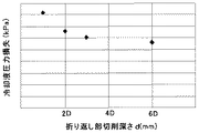
上記のようにして設けた折り返し流路部115の形状(切削深さ:d)と、内部通過流路の圧力損失との関係について、図7,8を用いて説明する。
冷却部材110内に多くの折り返し流路部115を設けるほど、冷却部材110内(内部通過流路)に冷却液を送液する際の圧力損失は大きくなり、液送ポンプ131の負担は大きくなる。しかしながら、図6(a),(b),(c)のような手順で、折り返し流路部115を加工する場合、図7に示す、折り返し流路部115の切削深さdを深くすることで圧力損失を軽減させることができる。
The relationship between the shape (cutting depth: d) of the folded flow path portion 115 provided as described above and the pressure loss of the internal passage flow path will be described with reference to FIGS.
The more the folded flow path portions 115 are provided in the cooling member 110, the larger the pressure loss when the cooling liquid is fed into the cooling member 110 (internal passage flow path), and the burden on the liquid feed pump 131 is increased. . However, when processing the folded channel portion 115 in the procedure as shown in FIGS. 6A, 6B, and 6C, the cutting depth d of the folded channel portion 115 shown in FIG. 7 is increased. The pressure loss can be reduced.

図8のグラフは、詳しくは図7に示すように内部通過流路を構成する直線流路部112の直径の値をDとし、折り返し流路部115の切削深さdを変化させた場合に、冷却部材110全体(内部通過流路)で生じる冷却液の圧力損失をプロットしたものである。基本的に切削深さdを深くするほど冷却液の圧力損失は低減する。しかしながら、あまりこれを深くしすぎると、加工上の困難性が生じたり、冷却液の内部通過流路の折り返し流路部115が用紙Pの用紙通過領域にかかってしまったり、あるいは冷却部材110の肥大化に繋がってしまう。このため、切削深さdによって設けられる冷却液の内部通過流路の折り返し流路部115の断面積は、それ以外の箇所における冷却液の内部通過流路の断面積の2倍程度であることが望ましい。   The graph of FIG. 8 shows the details when the value of the diameter of the straight flow path portion 112 constituting the internal passage flow path is D and the cutting depth d of the folded flow path portion 115 is changed as shown in FIG. The pressure loss of the cooling liquid generated in the whole cooling member 110 (internal passage flow path) is plotted. Basically, the pressure loss of the coolant decreases as the cutting depth d increases. However, if this is made too deep, processing difficulties may occur, the folding flow path portion 115 of the cooling liquid internal passage flow path may be applied to the paper passage area of the paper P, or the cooling member 110 It leads to enlargement. For this reason, the cross-sectional area of the return flow passage portion 115 of the coolant internal passage provided by the cutting depth d is approximately twice the cross-sectional area of the coolant internal passage in other locations. Is desirable.

したがって、冷却部材110内の内部通過流路を構成する折り返し流路部115の断面積を、並列して設けられる直線流路部112のよりも大きくすることで、折り返し流路部115での圧力損失を低減できる。   Therefore, the cross-sectional area of the folded flow path portion 115 that constitutes the internal passage flow path in the cooling member 110 is made larger than that of the straight flow path portion 112 provided in parallel, so that the pressure in the folded flow path portion 115 is increased. Loss can be reduced.

(実施例2)
本実施形態の冷却装置100の実施例2について、図を用いて説明する。また、実施例1と本実施例とでは、本実施例の冷却装置100が、折り返し流路部115を設ける用紙Pの用紙通過領域外に位置する冷却部材110の部分を、断熱部材117で覆っていることに係る点のみ異なる。したがって、実施例1と同様な構成・動作、及び作用・効果等については、適宜省略して説明する。また、同様な構成部材には、同一の符号を付して説明する。図9は、本実施例に係る冷却装置100に設けた冷却部材110の説明図である。
(Example 2)
Example 2 of the cooling device 100 of the present embodiment will be described with reference to the drawings. Further, in the first embodiment and the present embodiment, the cooling device 100 of the present embodiment covers a portion of the cooling member 110 located outside the paper passage area of the paper P where the folded flow path portion 115 is provided with the heat insulating member 117. The only difference is that the Therefore, the same configurations / operations, operations / effects, and the like as those of the first embodiment will be omitted as appropriate. Moreover, the same code | symbol is attached | subjected and demonstrated to the same structural member. FIG. 9 is an explanatory diagram of the cooling member 110 provided in the cooling device 100 according to the present embodiment.

図9に示すように、本実施例では冷却部材110の用紙Pの用紙通過領域外を断熱部材117で覆っている。冷却部材110は、高温の用紙Pが摺動接触する用紙通過領域内では高温になるが、用紙通過領域外では低温になるため、湿度の高い環境では冷却部材110の用紙通過領域外の部位で結露が生じやすい。冷却部材110に結露が生じると、冷却部材110と用紙Pの間に水分が入り込むことで、用紙Pの搬送がスムーズに行われなくなったり、用紙P上の画像品質を損なう原因になる。これを防ぐために、冷却部材110の用紙通過領域外は断熱部材117で覆われていることが望ましい。また、この断熱部材117の代わりに多孔質材などの吸湿部材を設けてもよい。また、断熱部材117を設ける範囲としては、冷却部材110の冷却面111が用紙Pと接触する範囲以外であれば図9に示す部分以外を覆っても良い。   As shown in FIG. 9, in this embodiment, the outside of the sheet passage area of the sheet P of the cooling member 110 is covered with a heat insulating member 117. The cooling member 110 has a high temperature in the paper passage region where the high-temperature paper P is in sliding contact, but the temperature is low outside the paper passage region. Therefore, in a high humidity environment, the cooling member 110 is located outside the paper passage region. Condensation is likely to occur. When condensation occurs on the cooling member 110, moisture enters between the cooling member 110 and the paper P, which may cause the paper P to not be transported smoothly or impair image quality on the paper P. In order to prevent this, it is desirable that the outside of the sheet passage area of the cooling member 110 is covered with a heat insulating member 117. Further, a moisture absorbing member such as a porous material may be provided instead of the heat insulating member 117. In addition, as a range in which the heat insulating member 117 is provided, a portion other than the portion shown in FIG. 9 may be covered as long as the cooling surface 111 of the cooling member 110 is outside the range in contact with the paper P.

本実施例の冷却装置100では、上記のように用紙Pの用紙通過領域外に位置する冷却部材110の部分を、断熱部材117で覆うことで、結露の発生を防ぎ結露に起因した不具合の発生を抑制することができる。   In the cooling device 100 of the present embodiment, as described above, the portion of the cooling member 110 located outside the paper passage area of the paper P is covered with the heat insulating member 117, thereby preventing the occurrence of condensation and generating a defect due to the condensation. Can be suppressed.

(実施例3)
本実施形態の冷却装置100の実施例3について、図を用いて説明する。また、実施例1と本実施例とでは、本実施例の冷却装置100が冷却部材110で用紙Pを冷却するのに無端ベルトを介して冷却していることに係る点のみ異なる。したがって、実施例1と同様な構成・動作、及び作用・効果等については、適宜省略して説明する。また、同様な構成部材には、同一の符号を付して説明する。図10は、本実施例に係る冷却装置100の構成説明図、図11は、本実施例に係る冷却装置100に設けた冷却部材110の説明図である。
(Example 3)
Example 3 of the cooling device 100 of the present embodiment will be described with reference to the drawings. Further, the first embodiment differs from the present embodiment only in that the cooling device 100 according to the present embodiment cools the paper P by the cooling member 110 via the endless belt. Therefore, the same configurations / operations, operations / effects, and the like as those of the first embodiment will be omitted as appropriate. Moreover, the same code | symbol is attached | subjected and demonstrated to the same structural member. FIG. 10 is an explanatory diagram of a configuration of the cooling device 100 according to the present embodiment, and FIG. 11 is an explanatory diagram of a cooling member 110 provided in the cooling device 100 according to the present embodiment.

図10に示すように、本実施例の冷却装置100には、定着後の用紙Pを無端ベルトを用いて搬送するベルト搬送装置140を有している。ベルト搬送装置140は、冷却部材110の冷却面111が上部無端ベルト142の内周面に接触するように配置される上部搬送部141と、上部無端ベルト142に直接、又は用紙Pを介して対向接触する下部無端ベルト146を有した下部搬送部145からなる。上部搬送部141は、複数の上部従動ローラ143と駆動ローラ144によって張架されて回転する上部無端ベルト142を有している。また、下部搬送部145に有した下部無端ベルト146は、2つの下部従動ローラ147に張架されて、上部無端ベルト142と直接、又は用紙Pを介して対向接触する。そして、上部無端ベルト142と下部無端ベルト146とで、定着後の高温状態の用紙Pを挟持しながら搬送を行う。   As shown in FIG. 10, the cooling device 100 according to the present exemplary embodiment includes a belt conveyance device 140 that conveys the fixed paper P using an endless belt. The belt conveyance device 140 is opposed to the upper conveyance unit 141 disposed so that the cooling surface 111 of the cooling member 110 is in contact with the inner peripheral surface of the upper endless belt 142, directly or via the paper P. It consists of the lower conveyance part 145 which has the lower endless belt 146 which contacts. The upper transport unit 141 includes an upper endless belt 142 that is stretched and rotated by a plurality of upper driven rollers 143 and a driving roller 144. Further, the lower endless belt 146 provided in the lower transport unit 145 is stretched around the two lower driven rollers 147 and contacts the upper endless belt 142 directly or via the paper P. Then, the upper endless belt 142 and the lower endless belt 146 convey the sheet P in a high temperature state after being fixed.

そして、冷却部材110の冷却面111が上部無端ベルト142の内周面に上方から摺動接触しながら上部無端ベルト142を介して高温状態の用紙Pから熱を吸熱する。
また、冷却部材110内の内部通過流路の折り返し流路部115を、図11に示すように用紙P、上部無端ベルト142の通過領域の外部に設けている。このように設けることで、単に用紙Pの用紙搬送領域外に折り返し流路部115設ける構成よりも、用紙Pの各無端ベルトを介した冷却能力を均一にする効果を得られる。
このような構成にすることで、冷却部材110の冷却面111と用紙Pの直接の摺動を防ぎ、用紙P上の定着後トナー像が崩れることを回避できる。
The cooling surface 111 of the cooling member 110 absorbs heat from the high-temperature paper P via the upper endless belt 142 while slidingly contacting the inner peripheral surface of the upper endless belt 142 from above.
Further, as shown in FIG. 11, the folded flow passage portion 115 of the internal passage flow passage in the cooling member 110 is provided outside the passage region of the paper P and the upper endless belt 142. By providing in this way, the effect of making the cooling capacity of the paper P through the endless belts uniform can be obtained more than the configuration in which the folded flow path portion 115 is simply provided outside the paper conveyance area of the paper P.
By adopting such a configuration, it is possible to prevent the cooling surface 111 of the cooling member 110 from sliding directly with the paper P, and to prevent the toner image after fixing on the paper P from collapsing.

また、本実施例では、ベルト搬送装置140の上部搬送部141にのみ、冷却装置100の冷却部材110を配置した構成について説明したが、本発明はこのような構成に限定されるものではない。例えば、ベルト搬送装置140の上部搬送部141及び下部搬送部145の各無端ベルトの内周面にそれぞれ冷却部材110を配置し、搬送される定着後の用紙Pを上部無端ベルト142及び下部無端ベルト146を介して挟持するように構成しても良い。このように構成することで、搬送される定着後の用紙Pを両面から冷却することができ、冷却効果を高めることができる。また、下部搬送部145に冷却部材110を配置して、搬送される定着後の用紙Pを下方から冷却する構成としても良い。   In the present embodiment, the configuration in which the cooling member 110 of the cooling device 100 is disposed only in the upper transport unit 141 of the belt transport device 140 has been described, but the present invention is not limited to such a configuration. For example, the cooling member 110 is disposed on the inner peripheral surface of each endless belt of the upper transport unit 141 and the lower transport unit 145 of the belt transport device 140, and the transported fixed sheet P is transported to the upper endless belt 142 and the lower endless belt. It may be configured to be held via 146. With this configuration, the fixed sheet P that is conveyed can be cooled from both sides, and the cooling effect can be enhanced. Alternatively, the cooling member 110 may be disposed in the lower transport unit 145 to cool the transported paper P that is transported from below.

(実施例4)
本実施形態の冷却装置100の実施例4について、図を用いて説明する。また、実施例3と本実施例とでは、本実施例の冷却装置100に具備する冷却部材110の内部通過流路を構成するのに、管路118を用いていることに係る点のみ異なる。したがって、実施例3と同様な構成・動作、及び作用・効果等については、適宜省略して説明する。また、同様な構成部材には、同一の符号を付して説明する。図12は、本実施例に係る冷却装置100に設けた冷却部材110の説明図である。図13は、本実施例に係る冷却部材110の製作方法の説明図であり、(a)が基材110dの溝部119に管路118を嵌め込む前を示し、(b)が基材110dの溝部119に管路118を嵌め込むんだ後を示している。
Example 4
Example 4 of the cooling device 100 of the present embodiment will be described with reference to the drawings. The third embodiment is different from the present embodiment only in that the pipe 118 is used to form the internal passage flow path of the cooling member 110 included in the cooling device 100 of the present embodiment. Therefore, the same configuration / operation, operation / effect, and the like as those of the third embodiment will be omitted as appropriate. Moreover, the same code | symbol is attached | subjected and demonstrated to the same structural member. FIG. 12 is an explanatory diagram of the cooling member 110 provided in the cooling device 100 according to the present embodiment. FIGS. 13A and 13B are explanatory diagrams of a method for manufacturing the cooling member 110 according to the present embodiment, in which FIG. 13A shows a state before fitting the pipe line 118 into the groove portion 119 of the base 110d, and FIG. 13B shows the base 110d. It shows after the pipe line 118 is fitted in the groove part 119.

図12に示すように、本実施例の冷却装置100では、実施例3(実施例1,2)のように基材110cの内部に直接、押出し加工や切削加工を施して内部通過流路を設けるのではなく、基材110dの溝部119に管路118を嵌め込むことで設けている。具体的には、管路118は、並列して設けられた直線流路部と、冷却液搬送方向下流側の直線流路部に冷却液を折り返させる折り返し流路部であるR状に加工されたR流路部とを形成するように折り曲げ加工された銅管である。また、冷却部材110の基材110dは、上記管路118を嵌め込む溝部119が形成されたアルミ材料等からなる部材である。そして、冷却部材110は、図13(a)に示すように基材110dの溝部119の図中上方から、図13(b)に示すように管路118を嵌め込む。このように嵌め込んだ後、伝熱製の高い接着剤や溶接、あるいは圧力などによって固定して冷却部材110を製作する。   As shown in FIG. 12, in the cooling device 100 of the present embodiment, as in the third embodiment (the first and second embodiments), the inner passage flow path is formed by directly extruding or cutting the inside of the substrate 110c. It is not provided, but is provided by fitting the pipe line 118 in the groove part 119 of the substrate 110d. Specifically, the pipe line 118 is processed into an R shape that is a straight flow path portion provided in parallel and a folded flow path portion that turns the cooling liquid back into the straight flow path portion downstream in the coolant transport direction. The copper tube is bent so as to form an R channel portion. Further, the base member 110d of the cooling member 110 is a member made of an aluminum material or the like in which a groove portion 119 into which the pipe line 118 is fitted is formed. Then, the cooling member 110 fits the pipe line 118 as shown in FIG. 13B from the upper side of the groove portion 119 of the base 110d as shown in FIG. 13A. After being fitted in this way, the cooling member 110 is manufactured by fixing with high heat transfer adhesive, welding, or pressure.

この冷却部材110では、冷却液の内部通過流路は銅管である管路118内部となる。このような冷却部材110においても管路118の折り返し流路部であるR流路部を、図12に示すように用紙P、上部無端ベルト142の通過領域の外部に設けることで用紙Pの冷却能力を均一にする効果を得られる。また、1本の銅管からなる管路118の曲げ加工によって並列した直線流路部と折り返し流路部とから構成される内部通過流路を設けているため、折り返し流路部(R流路部)での封止処理(シール処理)を要せず、冷却液漏れのリスクも低減できる。   In this cooling member 110, the internal passage for the coolant is inside the pipe line 118, which is a copper pipe. In such a cooling member 110 as well, the R flow path portion that is the folded flow path portion of the pipe line 118 is provided outside the passage region of the paper P and the upper endless belt 142 as shown in FIG. The effect of making the ability uniform can be obtained. In addition, since an internal passage channel composed of a straight channel portion and a folded channel portion arranged in parallel by bending a pipe line 118 made of a single copper pipe is provided, the folded channel portion (R channel) Sealing process (sealing process) is not required, and the risk of coolant leakage can be reduced.

(実施例5)
本実施形態の冷却装置100の実施例5について、図を用いて説明する。また、実施例4と本実施例とでは、次の点のみが異なる。本実施例の冷却装置100が、折り返し流路部である管路118のR流路部を設ける用紙P及び上部無端ベルト142の通過領域外の冷却部材110の画像形成に支障しない部分を、上述した実施例2と同様な断熱部材117で覆っていることに係る点である。したがって、実施例4、及び実施例2と同様な構成・動作、及び作用・効果等については、適宜省略して説明する。また、同様な構成部材には、同一の符号を付して説明する。図14は、本実施例に係る冷却装置100に設けた冷却部材110の説明図であり、(a)が、上方から上方から視た平面説明図であり、(b)が用紙搬送方向上流側から見た断面図である。
(Example 5)
Example 5 of the cooling device 100 of the present embodiment will be described with reference to the drawings. Further, the fourth embodiment is different from the present embodiment only in the following points. The cooling device 100 according to the present embodiment has a portion that does not hinder the image formation of the cooling member 110 outside the passage region of the sheet P and the upper endless belt 142 provided with the R flow path portion of the pipe line 118 that is the folded flow path portion. It is the point which concerns on covering with the heat insulation member 117 similar to 2nd Example. Therefore, the same configurations / operations, operations / effects, and the like as those of the fourth embodiment and the second embodiment will be appropriately omitted. Moreover, the same code | symbol is attached | subjected and demonstrated to the same structural member. FIG. 14 is an explanatory diagram of the cooling member 110 provided in the cooling device 100 according to the present embodiment. FIG. 14A is a plan explanatory diagram viewed from above from above, and FIG. 14B is an upstream side in the sheet conveyance direction. It is sectional drawing seen from.

本実施例の冷却装置100も実施例4と同様に、ベルト搬送装置140を設けている。このようにベルト搬送装置140を設けた構成でも、熱源である用紙Pの用紙通過範囲外、かつ上部無端ベルト142の通過範囲内である部位においても、冷却部材110は熱源である用紙Pが通過しないため低温となり結露が生じやすくなる。そこで、本実施例の冷却装置100でも、結露を防止するために上述した実施例2の構成と同様な断熱部材117で冷却部材110の両端部を覆うこととした。
しかし、本実施例の冷却装置100は実施例2の冷却装置の構成と異なり、ベルト搬送装置140を有しているため、冷却部材110の用紙通過領域外を実施例2の構成と同様に覆ってしまうと、次のような不都合が生じる。
Similarly to the fourth embodiment, the cooling device 100 according to the present embodiment also includes a belt conveyance device 140. Even in the configuration in which the belt conveyance device 140 is provided in this way, the cooling member 110 passes the paper P as the heat source even in a portion outside the paper passage range of the paper P as the heat source and within the passage range of the upper endless belt 142. Therefore, the temperature is low and condensation tends to occur. Therefore, also in the cooling device 100 of the present embodiment, both ends of the cooling member 110 are covered with the heat insulating member 117 similar to the configuration of the second embodiment described above in order to prevent condensation.
However, unlike the configuration of the cooling device of the second embodiment, the cooling device 100 of the present embodiment includes the belt conveyance device 140, and thus covers the outside of the sheet passage area of the cooling member 110 in the same manner as the configuration of the second embodiment. If this happens, the following inconvenience occurs.

一般的な上部搬送部と下部搬送部とを備え用紙Pを挟持搬送するベルト搬送装置では、各無端ベルトの移動方向(回転方向)に垂直なベルト幅を、搬送する用紙Pよりも広くしている。このため、実施例2の構成と同様に冷却部材110の用紙通過領域外の近くまで断熱部材117で覆ってしまうと、次のような不具合が生じるおそれがある。冷却部材110を設けた側の無端ベルトに断熱部材117が接触してしまい搬送不良を起こしたり、無端ベルトや断熱部材117が磨耗して寿命が短くなったり、異音が生じたりするといった不都合である。   In a belt transport apparatus that includes a general upper transport section and a lower transport section and sandwiches and transports paper P, the belt width perpendicular to the moving direction (rotation direction) of each endless belt is wider than that of the transported paper P. Yes. For this reason, if the cooling member 110 is covered with the heat insulating member 117 close to the outside of the sheet passage area of the cooling member 110 as in the configuration of the second embodiment, the following problems may occur. The heat-insulating member 117 comes into contact with the endless belt on the side where the cooling member 110 is provided, causing a conveyance failure, and the endless belt and the heat-insulating member 117 are worn out, resulting in a short life or abnormal noise. is there.

そこで、本実施例の冷却装置100では、図14(a),(b)に示すように冷却部材110の長手方向の両端部で、上部無端ベルト142に接触する可能性のある部分を除いた用紙通過領域外の部分を断熱部材117で覆っている。すなわち、図14(b)の断面図に示すように、冷却部材110の冷却面111では上部無端ベルト142の通過領域外を、その他の部位に関しては、図14(a),(b)に示すように用紙Pの用紙通過領域外を断熱部材117で覆うこととした。   Therefore, in the cooling device 100 of the present embodiment, as shown in FIGS. 14A and 14B, portions that may contact the upper endless belt 142 are excluded at both ends in the longitudinal direction of the cooling member 110. A portion outside the paper passage area is covered with a heat insulating member 117. That is, as shown in the cross-sectional view of FIG. 14 (b), the cooling surface 111 of the cooling member 110 is outside the passage region of the upper endless belt 142, and the other parts are shown in FIGS. 14 (a) and 14 (b). As described above, the outside of the sheet passage area of the sheet P is covered with the heat insulating member 117.

上記のように冷却部材110の長手方向の両端部を断熱部材117で覆うことで、次のような効果が得られる。冷却部材110を設けた側の無端ベルトである上部無端ベルト142の搬送を妨げないようにしつつ、用紙Pの用紙通過領域外かつ上部無端ベルト142の通過領域内である部位における結露も防止できるという効果である。また、冷却部材110の長手方向の両端部を覆う部材に関しては、断熱部材117の代わりに多孔質材などの吸湿部材を設けても良い。   The following effects are acquired by covering the both ends of the cooling member 110 in the longitudinal direction with the heat insulating member 117 as described above. It is possible to prevent dew condensation in a portion outside the paper passage area of the paper P and within the passage area of the upper endless belt 142 while preventing the conveyance of the upper endless belt 142 which is the endless belt on the side where the cooling member 110 is provided. It is an effect. Further, with respect to the member covering both ends of the cooling member 110 in the longitudinal direction, a moisture absorbing member such as a porous material may be provided instead of the heat insulating member 117.

(実施例6)
本実施形態の冷却装置100の実施例6について、図を用いて説明する。
実施例1乃至5の冷却装置では、冷却装置に具備した冷却部材の内部通過流路に有した折り返し流路部を、最も幅の大きい用紙Pが冷却部材の冷却面上を通過する用紙通過領域の外側になるように構成した例について説明した。
これに対して本実施例6以降の冷却装置100では、この冷却部材110の長手方向のサイズを上記実施形態1の冷却装置に比べて、少しでも小さくするために、最も幅の大きい用紙Pの画像形成領域Gの外側になるように構成している。
さらに、用紙Pの画像形成領域内において冷却部材110の長手方向の冷却効果の偏りの抑制と、冷却部材110を小型化とを好適に両立することができる、折り返し流路部115の配置位置を、折り返し流路部115の形状毎に導いた。
(Example 6)
Example 6 of the cooling device 100 of the present embodiment will be described with reference to the drawings.
In the cooling devices according to the first to fifth embodiments, the paper passage region in which the widest paper P passes over the cooling surface of the cooling member through the folded passage portion provided in the internal passage passage of the cooling member provided in the cooling device. The example configured to be outside the above has been described.
On the other hand, in the cooling device 100 of the sixth embodiment and later, in order to make the size of the cooling member 110 in the longitudinal direction as small as compared with the cooling device of the first embodiment, It is configured to be outside the image forming region G.
Further, the arrangement position of the folded flow path portion 115 that can suitably suppress both the uneven cooling effect of the cooling member 110 in the longitudinal direction and the downsizing of the cooling member 110 in the image forming area of the paper P can be achieved. Each of the folded flow path portions 115 was guided.

上記相違点に係る構成を除き、本実施例6以降の冷却装置100の基本的な構成は上記した実施例1乃至5の冷却装置の構成と同様である。したがって、実施例4、及び実施例2と同様な構成・動作、及び作用・効果等については、適宜省略して説明する。また、同様な構成部材には、同一の符号を付して説明する。図15は、本実施例に係る冷却装置100に設けた冷却部材110の例の説明図である。   Except for the configuration related to the above differences, the basic configuration of the cooling device 100 according to the sixth and subsequent embodiments is the same as the configuration of the cooling devices of the first to fifth embodiments described above. Therefore, the same configurations / operations, operations / effects, and the like as those of the fourth embodiment and the second embodiment will be appropriately omitted. Moreover, the same code | symbol is attached | subjected and demonstrated to the same structural member. FIG. 15 is an explanatory diagram of an example of the cooling member 110 provided in the cooling device 100 according to the present embodiment.

本実施例では、例えば図15に符号Gで示す用紙Pの画像形成領域外に折り返し流路部115を設けるように構成している。このように構成して、冷却部材110の長手方向の冷却面111の温度低下がなだらかな部分で用紙Pの画像形成領域を冷却することで、急激な冷却効果の変動が用紙Pの画像形成領域内で生じないようしている。そして、上記した実施例1乃至5の構成に比べ、冷却部材110の長手方向で、用紙Pの画像形成領域外の範囲、つまり、少なくとも余白部の幅だけ冷却部材110の幅を小さくすることができる。   In this embodiment, for example, the folded flow path portion 115 is provided outside the image forming area of the paper P indicated by G in FIG. By configuring in this way, the image forming area of the sheet P is cooled at a portion where the temperature drop of the cooling surface 111 in the longitudinal direction of the cooling member 110 is gentle. It does not occur within. Compared to the configurations of the first to fifth embodiments, the width of the cooling member 110 can be reduced in the longitudinal direction of the cooling member 110 in the range outside the image forming area of the paper P, that is, at least the width of the margin. it can.

ここで、上記実施例1乃至5で説明したように、折り返し流路部115を設けている冷却部材110の長手方向における両端近傍の冷却面111では、他の部分に比べ冷却効果が急激に高くなる現象が生じる。実施例1乃至5では、用紙Pの用紙通過領域外に折り返し流路部115を設け、なだらかに冷却効果が高くなる部分を用いて、用紙Pを冷却する構成とした。しかし、冷却効果の偏りにより、長手方向の端部と中央部である(用紙中心線M)とでは、光沢等の画像品質にムラが生じる現象は、あくまでも用紙Pの画像形成領域で生じる。実施例1乃至5のように構成することで、用紙Pの画像形成領域内においても冷却効果の偏りを好適に抑制できるもの、冷却部材110の長手方向のサイズが、余白部分の幅だけ大きくなる。   Here, as described in the first to fifth embodiments, the cooling surface 111 in the vicinity of both ends in the longitudinal direction of the cooling member 110 provided with the folded flow path portion 115 has a sharply higher cooling effect than the other portions. The phenomenon that occurs. In the first to fifth embodiments, the folded flow path portion 115 is provided outside the paper passage area of the paper P, and the paper P is cooled by using a portion where the cooling effect is gently increased. However, the phenomenon of unevenness in image quality such as gloss at the end and center in the longitudinal direction (sheet center line M) due to the uneven cooling effect occurs only in the image forming area of the sheet P. By configuring as in the first to fifth embodiments, it is possible to suitably suppress the uneven cooling effect even in the image forming area of the paper P, and the longitudinal size of the cooling member 110 is increased by the width of the margin portion. .

そこで、本実施例では、冷却部材110の長手方向の両端部に設けた折り返し流路部115で、冷却効果が急激に高まる現象について、再度、詳細に検討した。この現象は、実施例1乃至5で上記したように、主に冷却部材110の長手方向における単位幅当たりの、冷却液が内部通過流路の内周面に接触して熱交換を行う面積が、各直線流路部112を設けた範囲に比べ、折り返し流路部115で大きくなってしまうためである。
しかし、他の要因として、折り返し流路部115の流路、及び折り返し流路部115に接続される直線流路部112の折り返し流路部115に近接する部分の内周面に接触する冷却液の流速の変化が挙げられる。
Therefore, in this embodiment, the phenomenon in which the cooling effect rapidly increases in the folded flow path portions 115 provided at both ends in the longitudinal direction of the cooling member 110 was examined in detail again. As described above in the first to fifth embodiments, this phenomenon has an area where the cooling liquid contacts the inner peripheral surface of the internal passage and mainly performs heat exchange per unit width in the longitudinal direction of the cooling member 110. This is because the folded flow path portion 115 becomes larger than the range in which each straight flow path portion 112 is provided.
However, as another factor, the coolant that contacts the flow path of the folded flow path portion 115 and the inner peripheral surface of the portion near the folded flow path portion 115 of the straight flow path portion 112 connected to the folded flow path portion 115. The change in the flow rate is mentioned.

物体に接触することで熱吸収を行う流体による冷却効果は、物体に接触する流体の速度が速い程、一般に高くなる。この現象は、内部通過流路の内周面に接触して熱交換を行う冷却液を用いた本実施例6以降の冷却装置100においても同様に生じる。しかし、折り返し流路部115の流路、及び折り返し流路部115に接続される直線流路部112の折り返し流路部115に近接する部分の内周面に接触する冷却液の流速は、折り返し流路部115の形状及びその位置により変化する。   The cooling effect by the fluid that absorbs heat by coming into contact with the object generally increases as the speed of the fluid in contact with the object increases. This phenomenon also occurs in the cooling devices 100 in the sixth and subsequent embodiments that use a coolant that exchanges heat by contacting the inner peripheral surface of the internal passage. However, the flow rate of the cooling liquid that contacts the flow path of the folded flow path portion 115 and the inner peripheral surface of the portion near the folded flow path portion 115 of the straight flow path portion 112 connected to the folded flow path portion 115 is folded back. It changes depending on the shape of the flow path portion 115 and its position.

図16は、本実施例に係る冷却部材110に矩形状の折り返し流路部115を設け、折り返し流路部115の内側内壁面151の位置を画像形成領域外とした例の説明図である。また、図16(a)が矩形状の折り返し流路部115近傍における冷却液の流れの説明図、図16(b)が矩形状の折り返し流路部115の内側内壁面151位置における冷却効果の説明図である。そして、図16(c)が矩形状の折り返し流路部115の内側内壁面151位置と仮想円Cの中心位置Oとの位置関係、及び用紙Pの画像形成領域Gと境界位置Bとの位置関係の説明図である。   FIG. 16 is an explanatory diagram of an example in which the cooling member 110 according to the present embodiment is provided with a rectangular folded channel portion 115 and the position of the inner inner wall surface 151 of the folded channel portion 115 is outside the image forming region. FIG. 16A is an explanatory diagram of the flow of the cooling liquid in the vicinity of the rectangular folded channel portion 115, and FIG. 16B is the cooling effect at the position of the inner inner wall surface 151 of the rectangular folded channel portion 115. It is explanatory drawing. FIG. 16C shows the positional relationship between the position of the inner inner wall surface 151 of the rectangular folded channel portion 115 and the center position O of the virtual circle C, and the position of the image forming area G and the boundary position B of the paper P. It is explanatory drawing of a relationship.

図17は、本実施例に係る冷却部材110に矩形状の折り返し流路部115を設け、折り返し流路部115における仮想円Cの中心位置Oを画像形成領域外とした例の説明図である。また、図17(a)が矩形状の折り返し流路部115近傍における冷却液の流れの説明図、図17(b)が矩形状の折り返し流路部115の内側内壁面151位置における冷却効果の説明図である。そして、図17(c)が矩形状の折り返し流路部115の内側内壁面151位置と仮想円Cの中心位置Oとの位置関係、及び用紙Pの画像形成領域Gと境界位置Bとの位置関係の説明図である。   FIG. 17 is an explanatory diagram of an example in which the cooling member 110 according to the present embodiment is provided with a rectangular folded channel portion 115 and the center position O of the virtual circle C in the folded channel portion 115 is outside the image forming region. . FIG. 17A is an explanatory diagram of the flow of the cooling liquid in the vicinity of the rectangular folded channel portion 115, and FIG. 17B is a diagram illustrating the cooling effect at the position of the inner inner wall surface 151 of the rectangular folded channel portion 115. It is explanatory drawing. FIG. 17C shows the positional relationship between the position of the inner inner wall surface 151 of the rectangular folded channel portion 115 and the center position O of the virtual circle C, and the position of the image forming area G and the boundary position B of the paper P. It is explanatory drawing of a relationship.

本実施例では、図16、図17に示すように、冷却部材110の内部通過流路を用紙Pの搬送面に投影した場合に、折り返し流路部115の外郭線は矩形状の形状している。また、この折り返し流路部115は、冷却部材110の長手方向端部で封止部材116により封止されており、冷却部材110の長手端部と、折り返し流路部115の外側内壁面152とは用紙搬送方向に垂直な方向の位置が同じものとして説明する。   In the present embodiment, as shown in FIGS. 16 and 17, when the internal passage flow path of the cooling member 110 is projected onto the conveyance surface of the paper P, the outline of the folded flow path portion 115 has a rectangular shape. Yes. Further, the folded flow path portion 115 is sealed by the sealing member 116 at the longitudinal end portion of the cooling member 110, and the longitudinal end portion of the cooling member 110 and the outer inner wall surface 152 of the folded flow path portion 115 are In the following description, it is assumed that the position in the direction perpendicular to the paper transport direction is the same.

この折り返し流路部115は、冷却液搬送方向上流側の直線流路部112から下流側の直線流路部112に、流れる向きを変えて冷却液を導くものである。このため、折り返し流路部115の直線流路部112から離れた側の外側辺である外側内壁面152の角部近傍の、図中左下がりのハッチングを施した速度低下部Aでは、冷却液の顕著な速度低下が起こる。また、2つの直線流路部112が接続する側の内側辺である用紙搬送方向に平行な内側内壁面151近傍の図中左下がりのハッチングを施した速度低下部Aでも、冷却液の顕著な速度低下が起こる。   The folded flow path portion 115 changes the flow direction from the linear flow path portion 112 on the upstream side in the coolant transport direction to the straight flow path portion 112 on the downstream side, and guides the cooling liquid. For this reason, in the speed reduction portion A that is hatched in the lower left direction in the drawing, in the vicinity of the corner portion of the outer inner wall surface 152 that is the outer side of the folded flow passage portion 115 on the side away from the straight flow passage portion 112, the cooling liquid A noticeable speed reduction occurs. In addition, the cooling liquid is conspicuous even in the speed reduction portion A that is hatched in the lower left direction in the drawing in the vicinity of the inner inner wall surface 151 parallel to the sheet conveyance direction, which is the inner side on the side where the two linear flow path portions 112 are connected. A slowdown occurs.

そして、冷却液の主な流れは、顕著な速度低下が起こる領域を避けるようにして略円弧状の軌跡を描き、この円弧状の外周側の速度が速くなり、内周側の速度が遅くなる。このように冷却液の速度に変化が生じるため、上記したように折り返し流路部115の中の位置により冷却効果に差異が生じる。したがって、直線流路部112が折り返し流路部115に接続される位置、つまり、折り返し流路部115の内側内壁面151の位置により、折り返し流路部115近傍の直線流路部112の冷却効果も変動する。
そこで、発明者が検証を重ねた所、外側内壁面152の位置により影響を与える、折り返し流路部115に接続される直線流路部112による冷却効果に次のような傾向があることを見出した。外側内壁面152を、その用紙中心線Mから離れた側の一辺とする仮想正方形に内接する仮想円Cの中心位置を境とした折り返し流路部115の内側内壁面151の位置により、接続される直線流路部112による冷却効果に差異が生じる傾向があることを見出した。
Then, the main flow of the coolant draws a substantially arc-shaped locus so as to avoid a region where a remarkable speed reduction occurs, the speed on the outer peripheral side of the arc increases, and the speed on the inner peripheral side decreases. . As described above, since the speed of the coolant changes, the cooling effect varies depending on the position in the folded flow path 115 as described above. Accordingly, the cooling effect of the straight flow path portion 112 in the vicinity of the return flow path portion 115 depends on the position where the straight flow path portion 112 is connected to the return flow path portion 115, that is, the position of the inner inner wall surface 151 of the return flow path portion 115. Also fluctuate.
Therefore, when the inventor repeated verification, the inventors found that the cooling effect by the straight flow path portion 112 connected to the folded flow path portion 115 that has an influence on the position of the outer inner wall surface 152 has the following tendency. It was. The outer inner wall surface 152 is connected by the position of the inner inner wall surface 151 of the folded flow path portion 115 with the center position of the virtual circle C inscribed in the virtual square as one side away from the paper center line M. It has been found that there is a tendency for a difference in the cooling effect by the straight flow path portion 112.

まず、折り返し流路部115の内側内壁面151の位置が仮想円Cの中心位置Oと同じか、仮想円Cの中心位置Oよりも用紙搬送面に沿って搬送される用紙Pの中心が通る用紙搬送面上の直線である記録材中心線、つまり用紙中心線Mに近い場合について説明する。すなわち、仮想円Cの中心位置Oが、内側内壁面151上か、内側内壁面151よりも用紙中心線Mから離れている場合について説明する。
図16(a)に示すように、折り返し流路部115に有した矩形状の領域から十分離れた直線流路部112では、矩形状の領域に冷却液を送り込む上流側、及び矩形状の領域から冷却液が送り出される下流側ともに、その中心線に平行に冷却液が搬送される。また、搬送される冷却液の速度は、直接、冷却液が接触する内周側が遅く、内周側から離れた流路の中心線に近い部分ほど早くなる。
First, the position of the inner inner wall surface 151 of the folded flow path portion 115 is the same as the center position O of the virtual circle C, or the center of the paper P that is transported along the paper transport surface passes through the center position O of the virtual circle C. A case where the recording material center line that is a straight line on the sheet conveyance surface, that is, the sheet center line M is close will be described. That is, the case where the center position O of the virtual circle C is on the inner inner wall surface 151 or farther from the paper center line M than the inner inner wall surface 151 will be described.
As shown in FIG. 16 (a), in the straight flow path portion 112 sufficiently separated from the rectangular area included in the folded flow path section 115, the upstream side for feeding the coolant into the rectangular area, and the rectangular area The cooling liquid is conveyed parallel to the center line on both the downstream side from which the cooling liquid is sent out. Further, the speed of the cooling liquid to be transported is slower on the inner peripheral side where the cooling liquid directly contacts, and becomes faster as it is closer to the center line of the flow path away from the inner peripheral side.

一方、折り返し流路部115の矩形状の領域では、上記したように直線流路部112から離れた側の角部、及び2つの直線流路部112が接続する側の内壁部近傍で、冷却液の顕著な速度低下が生じる。このため、冷却液が略円弧状の軌道に沿って向きが変更されながら搬送されるとともに、折り返し流路部115の用紙搬送方向に平行な対称軸上の断面では略円弧状の外周側の速度が、内周側の速度よりも早くなる。また、折り返し流路部115の内側内壁面151と、2つの直線流路部112との境界部分Tptでは、いずれも冷却液の速度が顕著に低下する角部から離れているため、冷却液の搬送方向は各直線流路部112の中心線に倣って平行となる。そして、上記した折り返し流路部115の用紙搬送方向に平行な対称軸上の断面の速度変動にともない、冷却液の速度は略円弧状の軌道の外周側が速くなり、内周側が遅くなる。   On the other hand, in the rectangular region of the folded flow path portion 115, as described above, the cooling is performed near the corner portion on the side away from the straight flow path portion 112 and the inner wall portion on the side where the two straight flow path portions 112 are connected. A noticeable speed reduction of the liquid occurs. For this reason, the cooling liquid is conveyed while changing its direction along a substantially arc-shaped track, and the speed of the outer circumference side of the substantially circular arc shape in the cross section on the axis of symmetry of the folded flow path portion 115 parallel to the paper conveyance direction. However, it becomes faster than the speed on the inner circumference side. In addition, the boundary portion Tpt between the inner inner wall surface 151 of the folded flow path portion 115 and the two straight flow path portions 112 is away from the corner where the speed of the coolant is significantly reduced. The transport direction is parallel to the center line of each straight flow path portion 112. As the speed of the cross section on the axis of symmetry parallel to the paper conveyance direction of the folded flow path portion 115 changes, the coolant speed increases on the outer peripheral side of the substantially arc-shaped track and decreases on the inner peripheral side.

これらのため、折り返し流路部115の内側内壁面151と、2つの直線流路部112との境界部分Tptでは、図16(b)に右下がりのハッチングで示すように冷却効果が2つの直線流路部112が互いに接近した側が低下し、離間した側が上昇する。しかし、2つの境界で、低下する冷却効果と上昇する冷却効果とがほぼ等しくなるため、この境界部分Tptでの、冷却液の速度変動による顕著な冷却効果の変動は大きくない。   For these reasons, at the boundary portion Tpt between the inner inner wall surface 151 of the folded flow passage portion 115 and the two straight flow passage portions 112, the cooling effect has two straight lines as shown by the right-down hatching in FIG. The side where the flow path portions 112 approach each other is lowered, and the separated side is raised. However, since the cooling effect that decreases and the cooling effect that increases are almost equal at the two boundaries, the remarkable cooling effect variation due to the variation in the coolant speed at this boundary portion Tpt is not large.

したがって、冷却部材110の冷却面111における用紙搬送方向に垂直な方向の冷却効果の分布に与える影響は、冷却液が流路の内周面に接触して熱交換を行う面積が大きくなる矩形状の領域の領域の冷却効果が支配的になる。したがって、冷却面111による冷却効果が顕著に変化する部分は、折り返し流路部115の矩形状の領域となる。すなわち、図16(b)に示す折り返し流路部115の矩形状の領域の直線流路部112側の内壁面、つまり、内側内壁面151の位置(境界部分Tpt)がその境界位置Bとなる。   Therefore, the influence of the cooling surface 111 of the cooling member 110 on the distribution of the cooling effect in the direction perpendicular to the paper conveyance direction is a rectangular shape in which the cooling liquid comes into contact with the inner peripheral surface of the flow path to increase the area for heat exchange. The cooling effect in the region of the region becomes dominant. Therefore, a portion where the cooling effect by the cooling surface 111 changes significantly becomes a rectangular region of the folded flow path portion 115. That is, the inner wall surface on the linear channel portion 112 side of the rectangular region of the folded channel portion 115 shown in FIG. 16B, that is, the position of the inner inner wall surface 151 (boundary portion Tpt) becomes the boundary position B. .

そこで、本実施例では、図16(c)に示すように、用紙Pの画像形成領域Gの外側に境界位置B、すなわち折り返し流路部115の内側内壁面151を配置するように、冷却部材110を構成するようにした。このように構成することで、少なくとも画像形成領域G内の用紙搬送方向に垂直な方向の冷却効果の偏りと、冷却部材110の小型化とを好適に両立することが可能となる。   Therefore, in this embodiment, as shown in FIG. 16C, the cooling member is arranged so that the boundary position B, that is, the inner inner wall surface 151 of the folded flow path portion 115 is arranged outside the image forming region G of the paper P. 110 is configured. With such a configuration, it is possible to suitably achieve both the bias of the cooling effect at least in the direction perpendicular to the paper conveyance direction in the image forming region G and the size reduction of the cooling member 110.

次に、折り返し流路部115の内側内壁面151の位置が仮想円Cの中心位置Oよりも用紙中心線Mから遠い場合について説明する。すなわち、仮想円Cの中心位置Oが、内側内壁面151よりも用紙中心線Mに近い場合について説明する。
図17(a)に示すように、折り返し流路部115の矩形状の領域から十分離れた直線流路部112では、矩形状の領域に冷却液を送り込む上流側、及び矩形状の領域から冷却液が送り出される下流側ともに、その中心線に平行に冷却液が搬送される。また、搬送される冷却液の速度は、直接、冷却液が接触する内周側が遅く、内周側から離れた流路の中心線に近い部分ほど早くなる。
Next, a case where the position of the inner inner wall surface 151 of the folded flow path portion 115 is farther from the paper center line M than the center position O of the virtual circle C will be described. That is, a case where the center position O of the virtual circle C is closer to the paper center line M than the inner inner wall surface 151 will be described.
As shown in FIG. 17A, in the straight flow path portion 112 sufficiently separated from the rectangular area of the folded flow path section 115, cooling is performed from the upstream side where the coolant is sent to the rectangular area and from the rectangular area. The cooling liquid is conveyed parallel to the center line on both the downstream side where the liquid is sent out. Further, the speed of the cooling liquid to be transported is slower on the inner peripheral side where the cooling liquid directly contacts, and becomes faster as it is closer to the center line of the flow path away from the inner peripheral side.

一方、折り返し流路部115の矩形状の領域では、上記した例と同様に、直線流路部112から離れた側の角部、及び2つの直線流路部112が接続する側の内壁部近傍で、冷却液の顕著な速度低下が生じる。このため、冷却液が略円弧状の軌道に沿って向きが変更されながら搬送されるとともに、矩形状の領域の用紙搬送方向に平行な対称軸上の断面では略円弧状の軌道外周側の速度が、内周側の速度よりも早くなる。   On the other hand, in the rectangular region of the folded flow passage portion 115, as in the above example, the corner portion on the side away from the straight flow passage portion 112 and the vicinity of the inner wall portion on the side where the two straight flow passage portions 112 are connected. Thus, a significant speed reduction of the coolant occurs. For this reason, the coolant is conveyed while changing its direction along the substantially arcuate track, and the velocity on the outer periphery side of the substantially arcuate track in the cross section on the axis of symmetry parallel to the paper transport direction of the rectangular region. However, it becomes faster than the speed on the inner circumference side.

しかし、折り返し流路部115に有した矩形状の領域と、2つの直線流路部112との境界部分、つまり、内側内壁面151は、上記した例と異なり、いずれも冷却液の速度が顕著に低下する角部に近い。このため、冷却液搬送方向上流側の境界部分Tptでは、直線流路部112に対して略円弧状の軌道に沿って向きを変えた状態で冷却液が搬送される。そして、上記した折り返し流路部115に有した矩形状の領域の用紙搬送方向に平行な対称軸上の断面の速度変動にともない、冷却液の速度は外周側が速くなり、内周側が遅くなる。   However, unlike the above example, the boundary portion between the rectangular region in the folded flow passage portion 115 and the two straight flow passage portions 112, that is, the inner inner wall surface 151, has a remarkable coolant speed. It is close to the corner that falls. For this reason, in the boundary portion Tpt on the upstream side in the coolant transport direction, the coolant is transported in a state where the direction is changed along the substantially circular arc-shaped track with respect to the straight flow path portion 112. The speed of the cooling liquid increases on the outer peripheral side and decreases on the inner peripheral side in accordance with the speed fluctuation of the cross section on the axis of symmetry parallel to the sheet conveyance direction of the rectangular region included in the folded flow path portion 115 described above.

冷却液搬送方向下流側の境界部分Tptでは、上流側から略円弧状の軌道に沿って冷却液が搬送されてくるので、略円弧状の軌道の外周側では下流側の直線流路部112と平行な向きに冷却液が流れるが、内周側に近づく程、外周側へ傾いた向きに搬送される。そして、上記した矩形状の領域の用紙搬送方向に平行な対称軸上の断面の速度変動にともない、冷却液の速度は略円弧状の軌道の外周側が著しく速くなり、内周側が遅くなる。   In the boundary portion Tpt on the downstream side in the coolant transport direction, the coolant is transported from the upstream side along a substantially arc-shaped track. Although the coolant flows in a parallel direction, it is transported in a direction inclined toward the outer peripheral side as it approaches the inner peripheral side. As the speed of the section of the rectangular region on the axis of symmetry parallel to the paper conveyance direction changes, the coolant speed becomes significantly faster on the outer circumference side of the substantially arc-shaped track and slower on the inner circumference side.

これらのため、折り返し流路部115の矩形状の領域と、2つの直線流路部112との境界部分Tptでは、図17(b)に水平なハッチングで示すように冷却効果が2つの直線流路部112が互いに接近した側が低下し、離間した側が上昇する。特に、下流側の境界では2つの直線流路部112が互いに離間した側、つまり略円弧状の軌道の外周側が著しく上昇する。このため、矩形状の領域の冷却効果よりは低下するもの、冷却液の速度変動による顕著な冷却効果の変動が生じる。
したがって、用紙Pの画像形成領域Gの冷却効果の用紙搬送方向に垂直な方向の偏りを抑制するためには、用紙Pの画像形成領域Gの外側に冷却液の速度変動による顕著な冷却効果の変動が生じる部分を配置する必要がある。
For these reasons, at the boundary portion Tpt between the rectangular region of the folded flow path portion 115 and the two straight flow path portions 112, the cooling effect has two linear flows as shown by horizontal hatching in FIG. The sides where the path portions 112 approach each other are lowered, and the separated sides are raised. In particular, at the downstream boundary, the side where the two linear flow path portions 112 are separated from each other, that is, the outer peripheral side of the substantially arc-shaped track significantly rises. For this reason, although the cooling effect is lower than that of the rectangular region, a significant change in the cooling effect due to a change in the speed of the coolant occurs.
Therefore, in order to suppress the deviation of the cooling effect of the image forming area G of the paper P in the direction perpendicular to the paper conveyance direction, a remarkable cooling effect due to the fluctuation of the speed of the cooling liquid is provided outside the image forming area G of the paper P. It is necessary to arrange the part where the fluctuation occurs.

そこで、仮想円Cの中心位置の境界部分Tpcで、検証を行なった所、上記した例よりは冷却効果が増すもの、顕著な冷却効果の増大は抑制することができた。
この境界部分Tpcでは、上記した例で説明した境界位置Bと同様に、上流側及び下流側の2つの境界で、低下する冷却効果と上昇する冷却効果とがほぼ等しくなるため、この境界部分Tpcでの、冷却液の速度変動による顕著な冷却効果の変動を抑制できる。
Therefore, when the verification was performed at the boundary portion Tpc at the center position of the virtual circle C, the cooling effect was increased as compared with the above-described example, and a significant increase in the cooling effect could be suppressed.
In this boundary portion Tpc, as in the boundary position B described in the above example, the cooling effect that decreases and the cooling effect that increases are substantially equal at the two boundaries on the upstream side and the downstream side. Thus, it is possible to suppress a significant variation in the cooling effect due to a variation in the speed of the coolant.

そこで、折り返し流路部115の内側内壁面151の位置が仮想円Cの中心位置Oよりも用紙中心線Mから遠い場合、仮想円Cの境界部分Tpcを、境界位置Bとした。そして、図17(c)に示すように、用紙Pの画像形成領域Gの外側に境界位置B、すなわち仮想円Cの中心位置O(境界部分Tpc)を配置するように、冷却部材110を構成するようにした。このように構成することで、少なくとも画像形成領域G内の用紙搬送方向に垂直な方向の冷却効果の偏りと、冷却部材110の小型化とを好適に両立することが可能となる。   Therefore, when the position of the inner inner wall surface 151 of the folded flow path portion 115 is farther from the paper center line M than the center position O of the virtual circle C, the boundary portion Tpc of the virtual circle C is set as the boundary position B. Then, as shown in FIG. 17C, the cooling member 110 is configured so that the boundary position B, that is, the center position O (boundary portion Tpc) of the virtual circle C is arranged outside the image forming area G of the paper P. I tried to do it. With such a configuration, it is possible to suitably achieve both the bias of the cooling effect at least in the direction perpendicular to the paper conveyance direction in the image forming region G and the size reduction of the cooling member 110.

なお、冷却部材110の両端部を断熱部材で覆う場合には、ベルト部材を介さず、冷却面111と用紙Pとが摺動接触する構成では、上記した実施例2の構成と同様に、用紙Pの搬送に支障しない用紙Pの通過領域外の部分を断熱部材で覆う。また、ベルト搬送装置の無端ベルトを介して、冷却面と用紙Pとが摺動接触する構成では、上記した実施例5の構成と同様に、無端ベルトに接触する可能性のある部分を除いた用紙通過領域外の部分を断熱部材で覆う。また、以下に説明する実施例7、8も同様である。   When both ends of the cooling member 110 are covered with a heat insulating member, in the configuration in which the cooling surface 111 and the paper P are in sliding contact without using the belt member, the paper is similar to the configuration of the second embodiment described above. A portion outside the passage region of the paper P that does not interfere with the conveyance of the P is covered with a heat insulating member. Further, in the configuration in which the cooling surface and the paper P are in sliding contact via the endless belt of the belt conveying device, the portion that may contact the endless belt is excluded as in the configuration of the fifth embodiment. A portion outside the paper passage area is covered with a heat insulating member. The same applies to Examples 7 and 8 described below.

(実施例7)
本実施形態の冷却部材110の実施例7について、複数の例を挙げ、図を用いて説明する。
図18は、本実施例に係る冷却部材110に円弧状の折り返し流路部115を設けた例の説明図である。また、図18(a)が円弧状の折り返し流路部115近傍における冷却液の流れの説明図、図18(b)が円弧状の折り返し流路部115の境界位置Bにおける冷却効果の説明図である。そして、図18(c)が円弧状の折り返し流路部115における用紙Pの画像形成領域Gと境界位置Bとの位置関係の説明図である。なお、この折り返し流路部115は、内周側及び外周側の内周面の外郭線が、同一の中心位置で曲率半径がそれぞれ一定の曲線、すなわち、閉じていない真円、又は真円の一部分からなる曲線(部)ともいえる。
(Example 7)
Example 7 of the cooling member 110 of the present embodiment will be described with reference to the drawings by giving a plurality of examples.
FIG. 18 is an explanatory diagram of an example in which an arcuate folded channel portion 115 is provided in the cooling member 110 according to the present embodiment. 18A is an explanatory diagram of the flow of the cooling liquid in the vicinity of the arcuate folded channel portion 115, and FIG. 18B is an explanatory diagram of the cooling effect at the boundary position B of the arcuate folded channel portion 115. It is. FIG. 18C is an explanatory diagram of the positional relationship between the image forming area G and the boundary position B of the paper P in the arcuate folded flow path portion 115. The folded flow path portion 115 has an inner peripheral surface and an outer peripheral surface whose outer peripheral lines have a constant curvature radius at the same center position, that is, a non-closed perfect circle, or a perfect circle It can also be said to be a curve (part) consisting of a part.

図19は、本実施例に係る冷却部材110に曲線部を有した折り返し流路部115を設けた例の説明図である。詳しくは、内周側の内周面が円弧状の外郭線を描き、外周側が楕円状の曲線部からなる。また、図19(a)が曲線部を有した折り返し流路部115近傍における冷却液の流れの説明図、図19(b)が曲線部を有した折り返し流路部115の各編曲点位置における冷却効果の説明図である。そして、図19(c)が曲線部を有した折り返し流路部115の用紙Pの画像形成領域Gと境界位置Bとの位置関係の説明図である。   FIG. 19 is an explanatory diagram of an example in which a folded channel portion 115 having a curved portion is provided in the cooling member 110 according to the present embodiment. Specifically, the inner peripheral surface of the inner peripheral side draws an arcuate outline, and the outer peripheral side is composed of an elliptical curved portion. Further, FIG. 19A is an explanatory diagram of the flow of the cooling liquid in the vicinity of the folded flow path portion 115 having a curved portion, and FIG. 19B is a diagram illustrating the position of each folding point of the folded flow path portion 115 having a curved portion. It is explanatory drawing of a cooling effect. FIG. 19C is an explanatory diagram of the positional relationship between the image forming region G and the boundary position B of the paper P in the folded flow path portion 115 having a curved portion.

図20は、本実施例に係る冷却部材110に曲線部を有した折り返し流路部115を設けた別例の説明図である。詳しくは、内周側及び外周側の内周面の外郭線が、それそれ一定の曲率半径を有しているもの、内周側と外周側とでは、中心位置が異なっている。また、図20(a)が、この別例における、曲線部を有した折り返し流路部115近傍における冷却液の流れの説明図、図20(b)、この別例における、曲線部を有した折り返し流路部115の各編曲点位置における冷却効果の説明図である。そして、図19(c)が、この別例における、曲線部を有した折り返し流路部115の用紙Pの画像形成領域Gと境界位置Bとの位置関係の説明図である。   FIG. 20 is an explanatory diagram of another example in which the cooling channel 110 according to the present embodiment is provided with the folded channel portion 115 having a curved portion. Specifically, the outer peripheral lines on the inner peripheral side and the outer peripheral side have constant curvature radii, and the central positions are different between the inner peripheral side and the outer peripheral side. 20A is an explanatory diagram of the flow of the cooling liquid in the vicinity of the folded channel portion 115 having the curved portion in this other example, and FIG. 20B has the curved portion in this different example. It is explanatory drawing of the cooling effect in each arrangement | positioning point position of the return flow path part 115. FIG. FIG. 19C is an explanatory diagram of the positional relationship between the image forming region G and the boundary position B of the paper P in the folded flow path portion 115 having a curved portion in this other example.

本実施例の各例は、いずれも、内周側及び外周側の内周面の外郭線が、一定又は変化する曲率をもった曲線部からなる。そのため、上記実施例6で説明した、外郭線が矩形状の形状をした折り返し流路部とは異なり、速度低下部Aが発生し難く、発生したとしてもその範囲が、外郭線が矩形状の形状をした折り返し流路部に比べて小さい。
したがって、以下の折り返し流路部の形状の各例では、外郭線が矩形状の形状をした折り返し流路部の構成に比べ、冷却液の速度変動の影響も少ない。
なお、以下の各例の説明では、基本的な構成や、作用が大きく異ならないため、折り返し流路部115の符号に符番a,b,cを付し、共通する部材や編曲点符号等については、同一の符号を用いて説明する。
Each example of the present embodiment is composed of a curved portion having a constant or variable curvature of the outer peripheral line of the inner peripheral surface on the inner peripheral side and the outer peripheral side. Therefore, unlike the folded flow path portion in which the contour line has a rectangular shape described in the sixth embodiment, the speed reduction portion A is unlikely to occur, and even if it occurs, the range of the contour line is rectangular. Smaller than the shaped folded channel section.
Therefore, in each example of the shape of the folded flow path portion below, the influence of fluctuations in the speed of the cooling liquid is less than that of the configuration of the folded flow path portion having a rectangular outline.
In the following description of each example, since the basic configuration and operation are not greatly different, reference numerals a, b, and c are attached to the reference numerals of the folded flow path section 115, and common members, bending point codes, etc. Will be described using the same reference numerals.

まず、図18を用いて、円弧状の折り返し流路部115aの例について説明する。
図18(a)に示すように、折り返し流路部115aに有した円弧状の領域から十分離れた直線流路部112では、円弧状の領域に冷却液を送り込む上流側、及び円弧状の領域から冷却液が送り出される下流側ともに、その中心線に略平行に冷却液が搬送される。また、搬送される冷却液の速度は、直接、冷却液が接触する内周側が遅く、内周側から離れた流路の中心線に近い部分ほど早くなる。
First, an example of the arcuate folded channel portion 115a will be described with reference to FIG.
As shown in FIG. 18 (a), in the straight flow path 112 that is sufficiently away from the arcuate area of the folded flow path 115a, the upstream side that feeds the coolant into the arcuate area, and the arcuate area The coolant is conveyed substantially parallel to the center line on both the downstream side from which the coolant is sent out. Further, the speed of the cooling liquid to be transported is slower on the inner peripheral side where the cooling liquid directly contacts, and becomes faster as it is closer to the center line of the flow path away from the inner peripheral side.

また、折り返し流路部115aと2つの直線流路部が交わる境界部分Tpcでは、上記した矩形の折り返し流路部のように直線流路部112から離れた側の角部はなく、かつ、2つの直線流路部112が接続する部分も円弧状の軌跡を描いて接続される。このため、図18(a)に示すように、円弧の中心位置を通る用紙搬送方向に垂直な直線が、内側内壁面に交差する前後に速度低下部Aが発生するおそれもあるが、実施例6の構成のように顕著な冷却液の速度低下が生じることはない。しかし、この円弧状の流路の区間では、中心位置Oを中心とした遠心力の作用により、中心位置Oから離れた側ほど冷却液の速度が増し、中心位置Oに近い側ほど冷却液の速度が低下する。   Further, at the boundary portion Tpc where the folded flow path portion 115a and the two straight flow path portions intersect, there is no corner on the side away from the straight flow path portion 112 like the rectangular folded flow path portion described above, and 2 The portions to which the two straight flow path portions 112 are connected are also drawn in an arcuate locus. For this reason, as shown in FIG. 18A, there is a possibility that the speed reduction portion A may occur before and after the straight line passing through the center position of the arc and perpendicular to the sheet conveyance direction intersects the inner inner wall surface. As in the configuration of 6, the cooling liquid speed is not significantly reduced. However, in this arc-shaped channel section, the speed of the coolant increases as the distance from the center position O increases due to the action of the centrifugal force centered on the center position O, and the coolant flows closer to the center position O. The speed is reduced.

また、図18(a)〜(c)に示すように、2つの直線流路部112と交わる、h1、h2、h3、及びh4の4つの編曲点が形成されており、この前後で冷却液の方向が変化するため、速度変動が生じることとなる。そして、上記遠心力と編曲点での速度変動により、図18(b)に右下がりのハッチングで示すように冷却効果が2つの直線流路部112が互いに接近した側が低下し、離間した側が上昇する。しかし、2つの境界で、低下する冷却効果と上昇する冷却効果とがほぼ等しくなるため、この境界部分Tptでの、冷却液の速度変動による顕著な冷却効果の変動は大きくない。
そこで、この円弧状の折り返し流路部115aでは、円弧の中心である中心位置Oを通る境界部分Tpcを境界位置Bとした。
Also, as shown in FIGS. 18A to 18C, four bending points h1, h2, h3, and h4 intersecting with the two straight flow path portions 112 are formed, and before and after the cooling liquid As the direction of changes, speed fluctuation occurs. Then, due to the above-mentioned centrifugal force and speed fluctuation at the arrangement point, the cooling effect is lowered on the side where the two linear flow path portions 112 approach each other, and the separated side rises, as shown by the right-down hatching in FIG. To do. However, since the cooling effect that decreases and the cooling effect that increases are almost equal at the two boundaries, the remarkable cooling effect variation due to the variation in the coolant speed at this boundary portion Tpt is not large.
Therefore, in this arcuate folded channel portion 115a, the boundary portion Tpc passing through the center position O which is the center of the arc is defined as the boundary position B.

次に、図19を用いて、曲線部を有した折り返し流路部115bを設けた例について説明する。この例の折り返し流路部115bは、内周側、つまり2つの直線流路部112が互いに接近した側の内周面の外角線が円弧であり、外周側つまり2つの直線流路部112が互いに離間した側の内周面の外角線が、2つの焦点を基準とした楕円の半分の曲線部分からなる。なお、このような形状は、鋼管等の肉厚が極端に薄いものや、逆に厚いもの、加工手順を簡略化した曲げ加工等を施したもので意図せず生じる場合がある。また、意図してこのような加工を施す場合もある。   Next, an example in which the folded channel portion 115b having a curved portion is provided will be described with reference to FIG. In this example, the folded flow path portion 115b has an arc on the outer peripheral side, that is, the two straight flow path portions 112, on the inner peripheral side, that is, the inner peripheral surface on the side where the two straight flow path portions 112 approach each other. The outer corner lines of the inner peripheral surfaces on the sides that are separated from each other are made up of curved portions that are half of an ellipse based on two focal points. Such a shape may occur unintentionally with a steel pipe or the like having an extremely thin wall thickness, conversely with a thick wall, or a bending process that simplifies the processing procedure. In some cases, such processing is intentionally performed.

この曲線部を有した折り返し流路部115bは、上記したように外周側と内周側の外郭線の形状が異なるため、2つの直線流路部112との4つの編曲点の用紙搬送方向に垂直な方向の位置が外周側と内周側で異なっている。また、用紙搬送方向に垂直な方向に平行な2つの直線流路部112の対称軸が、この折り返し流路部115bと交差する部分の流路幅が最も狭くなるように構成されている。また、内周側の変曲点h2、h3は、内周側の内壁面における外郭線の中心位置Oを通る境界部分Tpoであり、外周側の変曲点h1、h4は、外周側の内壁面における外郭線である楕円の2つの焦点の間の中点を通る境界部分Tpdである。   As described above, the folded flow path portion 115b having the curved portion has different outlines on the outer peripheral side and the inner peripheral side, and therefore, in the sheet conveying direction of the four bending points between the two straight flow path portions 112. The position in the vertical direction is different between the outer peripheral side and the inner peripheral side. Further, the symmetrical axis of the two straight flow path portions 112 parallel to the direction perpendicular to the paper transport direction is configured such that the flow path width of the portion intersecting with the folded flow path portion 115b is the narrowest. Further, the inflection points h2 and h3 on the inner peripheral side are boundary portions Tpo passing through the center position O of the outer contour line on the inner wall surface on the inner peripheral side, and the inflection points h1 and h4 on the outer peripheral side are the inner peripheral side inner walls. This is a boundary portion Tpd that passes through a midpoint between two focal points of an ellipse that is an outline on the wall surface.

加えて、図19(a)に示すように、内周側の円弧における変曲点h2、h3を通る境界部分Tpoの方が、外周側の変曲点h1、h4が通る境界部分Tpdよりも、用紙中心線Mから遠い。このため、冷却液の移動角度や速度変化が、境界部分Tpoの方が、境界部分Tpdよりも大きくなる。これらのため、図19(b)に示すように、内周側の円弧における変曲点h2、h3を通る境界部分Tpoの位置では冷却効果の差異を吸収できない。
そして、2つの直線流路部112に接続する外周側の円弧における変曲点h1、h4が通る境界部分Tpdの位置で、ようやく、2つの境界の冷却効果をほぼ等しくすることができる。
In addition, as shown in FIG. 19A, the boundary portion Tpo passing through the inflection points h2 and h3 in the arc on the inner peripheral side is more than the boundary portion Tpd passing through the inflection points h1 and h4 on the outer peripheral side. , Far from the paper center line M. For this reason, the moving angle and speed change of the coolant are larger at the boundary portion Tpo than at the boundary portion Tpd. For these reasons, as shown in FIG. 19B, the difference in cooling effect cannot be absorbed at the position of the boundary portion Tpo passing through the inflection points h2 and h3 in the arc on the inner peripheral side.
Finally, at the position of the boundary portion Tpd through which the inflection points h1 and h4 in the arc on the outer peripheral side connected to the two straight flow channel portions 112 pass, the cooling effect of the two boundaries can be made substantially equal.

上記のように、外周側と内周側の変曲点、及び境界部分の用紙中心線Mからの距離が異なる場合に、2つの直線流路部112との変曲点位置が用紙中心線Mに近い側で2つの境界の冷却効果をほぼ等しくできる理由としては、次の理由が考えられる。
用紙中心線Mに近い側の変曲点よりも、さらに用紙中心線Mに近い側は、2つの直線流路部112の断面位置となり、断面積の変化による速度変動等が低減されるためと考えられる。
そこで、この曲線部を有した折り返し流路部115bでは、外周側の外郭線の2つの焦点の中点と、変曲点h1,h4を通る境界部分Tpdを境界位置Bとした。
As described above, when the inflection points on the outer peripheral side and the inner peripheral side and the distance from the paper center line M at the boundary portion are different, the position of the inflection point between the two straight flow path portions 112 is the paper center line M. The reason why the cooling effect of the two boundaries can be made substantially equal on the side close to is as follows.
This is because the side closer to the paper center line M than the inflection point on the side closer to the paper center line M is the cross-sectional position of the two straight flow path portions 112, and speed fluctuations due to changes in the cross-sectional area are reduced. Conceivable.
Therefore, in the folded flow path portion 115b having the curved portion, the boundary portion Tpd passing through the midpoint between the two focal points of the outer peripheral line and the inflection points h1 and h4 is defined as the boundary position B.

次に、図20を用いて、曲線部を有した折り返し流路部の別例である、折り返し流路部115cを設けた例について説明する。この例の折り返し流路部115cは、上記した折り返し流路部115bと異なり、内周側及び外周側の内周面が外郭線が、いずれも円弧である。しかし、各円弧の中心位置が、用紙搬送方向に垂直な方向にずれている。具体的には、外周側の円弧、つまり、2つの直線流路部112が互いに離間した側の直線流路部112に接続する円弧における外角線の中心位置O2の方が、内周側の円弧における外郭線の中心位置O1よりも、用紙中心線Mから離れている。そして、外周側の円弧の方が半径r2が、内周側の円弧の半径r1よりも大きい。   Next, an example in which the folded flow path portion 115c, which is another example of the folded flow path portion having the curved portion, is provided will be described with reference to FIG. Unlike the above-described folded flow path portion 115b, the folded flow path portion 115c of this example has an outer peripheral line on the inner peripheral surface on the inner peripheral side and the outer peripheral side, both of which are arcs. However, the center position of each arc is shifted in a direction perpendicular to the paper transport direction. Specifically, the outer peripheral arc, that is, the center position O2 of the outer corner line in the arc connected to the linear flow path 112 on the side where the two straight flow path portions 112 are separated from each other is the inner circular arc. Is located farther from the paper center line M than the center position O1 of the contour line. The radius r2 of the arc on the outer peripheral side is larger than the radius r1 of the arc on the inner peripheral side.

すなわち、用紙搬送方向に垂直な方向に平行な2つの直線流路部112の対称軸が、この折り返し流路部115cと交差する部分の、流路幅が最も広くなるように構成されている。また、この折り返し流路部115cでは、流路の中心線に垂直な断面積を略一定に保つようには構成されえとらず、流路幅の変化にほぼ比例して流路の中心線に垂直な断面積が変化する。したがって、上記流路幅が広くなる部分の内周側には、上記した折り返し流路部115a,bに比べ大きな速度低下部Aが生じる可能性が高い。   In other words, the symmetrical axis of the two linear flow path portions 112 parallel to the direction perpendicular to the paper transport direction is configured such that the flow path width is the widest at the portion intersecting with the folded flow path portion 115c. In addition, the folded flow path portion 115c cannot be configured to keep the cross-sectional area perpendicular to the center line of the flow path substantially constant, and is substantially proportional to the change in the flow path width. The vertical cross section changes. Therefore, there is a high possibility that a larger speed reduction portion A is generated on the inner peripheral side of the portion where the flow passage width is wider than the above-described folded flow passage portions 115a and 115b.

また、冷却液搬送方向上流側の直線流路部112から移動してきた冷却液は、移動方向の断面積が大きくなるため、外周側が速度が速くなる傾向はあるもの、断面で平均した速度は遅くなる。しかし、上記した流路幅が最も広くなる部分から、冷却液搬送方向下流側の直線流路部112に、冷却液が向かう際には、流路が狭くなるにしたがい、流路の中心線に垂直な断面積が狭くなり、冷却液の速度が速くなる。
したがって、図20(a)に示すように、外周側の円弧の外郭線の円弧における中心位置O2と、変曲点h1,h4とを通る境界部分Tp2では、冷却液搬送方向上流側の境界では冷却液の速度はあまり速くならないが、下流側の境界では速くなる。このため、図20(b)に示すように、外周側の円弧における変曲点h1、h4を通る境界部分Tp2の位置では冷却効果の差異を吸収できない。
In addition, the coolant that has moved from the straight flow path portion 112 on the upstream side in the coolant transport direction has a large cross-sectional area in the travel direction, so the outer peripheral side tends to increase in speed, but the average speed in the cross section is slow. Become. However, when the coolant flows from the portion where the channel width is the widest to the linear channel 112 on the downstream side in the coolant transport direction, the channel becomes narrower as the channel becomes narrower. The vertical cross-sectional area is narrowed and the speed of the coolant is increased.
Therefore, as shown in FIG. 20 (a), at the boundary portion Tp2 passing through the center position O2 in the arc of the outer peripheral arc and the inflection points h1 and h4, at the boundary on the upstream side in the coolant conveyance direction, The speed of the cooling liquid is not very fast, but is fast at the downstream boundary. For this reason, as shown in FIG.20 (b), the difference of a cooling effect cannot be absorbed in the position of the boundary part Tp2 which passes along the inflection points h1 and h4 in the circular arc on the outer peripheral side.

そして、2つの直線流路部112に接続する内周側の円弧における中心位置O1と、変曲点h2、h3が通る境界部分Tp1の位置で、ようやく、2つの境界の冷却効果をほぼ等しくすることができる。このように外周側と内周側の変曲点、及び境界部分の用紙中心線Mからの距離が異なる場合に、2つの直線流路部112との変曲点位置が用紙中心線Mに近い側で2つの境界の冷却効果をほぼ等しくできる理由は、折り返し流路部115bの理由と同様と考えられる。
そこで、この曲線部を有した折り返し流路部115cでは、内周側の外郭線の中心位置O1と、変曲点h2,h3を通る境界部分Tp1を境界位置Bとした。
Finally, the cooling effect of the two boundaries is almost equalized at the center position O1 in the arc on the inner peripheral side connected to the two straight flow path portions 112 and the position of the boundary portion Tp1 through which the inflection points h2 and h3 pass. be able to. Thus, when the inflection points on the outer peripheral side and the inner peripheral side and the distance from the paper center line M at the boundary portion are different, the positions of the inflection points with the two straight flow path portions 112 are close to the paper center line M. The reason why the cooling effect of the two boundaries can be made substantially equal on the side is considered to be the same as the reason for the folded flow path portion 115b.
Therefore, in the folded flow path portion 115c having the curved portion, the boundary position B is defined as the center position O1 of the outer peripheral line on the inner peripheral side and the boundary portion Tp1 passing through the inflection points h2 and h3.

上記したように、円弧状の折り返し流路部115a、及び外周側と内周側の変曲点、及び境界部分の用紙中心線Mからの距離が異なる曲線部を有した折り返し流路部115b,cは、いずれも、曲線部を有した折り返し流路部である。ここで、円弧状の折り返し流路部115aも、外周側と内周側の円弧の中心位置をずれせば、曲線部を有した折り返し流路部115cと同様な構成となる。逆に、曲線部を有した折り返し流路部115cは、外周側と内周側の円弧の中心位置を同じ位置にすれば、円弧状の折り返し流路部115aと同様な構成となる。すなわち、上記した折り返し流路部115a,b,cは、いずれも曲線部を有した折り返し流路部115a,b,cといえる。   As described above, the arcuate folded channel portion 115a and the folded channel portion 115b having curved portions having different distances from the inflection points on the outer peripheral side and the inner peripheral side and the paper center line M of the boundary portion, Each c is a folded channel portion having a curved portion. Here, the arcuate folded channel portion 115a also has the same configuration as the folded channel portion 115c having a curved portion if the center positions of the arcs on the outer circumferential side and the inner circumferential side are shifted. Conversely, the folded channel portion 115c having the curved portion has the same configuration as the arc-shaped folded channel portion 115a if the center positions of the arcs on the outer circumferential side and the inner circumferential side are the same. That is, it can be said that the above-described folded flow path portions 115a, b, and c are the folded flow path portions 115a, b, and c each having a curved portion.

そして、上記した各曲線部を有した折り返し流路部115では直線流路部112の外郭線に接続する曲線部を有した構成において、折り返し流路部115と直線流路部112とが接続する変曲点が画像形成領域外になるように折り返し流路部115を配置している。このように各曲線部を有した折り返し流路部115を構成することで、次のような効果を奏することができる。直線流路部112と接続する折り返し流路部115に曲線部を有している内部通過流路の構成で、少なくとも画像形成領域G内の用紙搬送方向に垂直な方向の冷却効果の偏りの抑制と、冷却部材の小型化とを好適に両立することが可能となる。   The folded channel portion 115 having each curved portion described above has a curved portion connected to the outline of the straight channel portion 112, and the folded channel portion 115 and the straight channel portion 112 are connected. The folded channel portion 115 is arranged so that the inflection point is outside the image forming area. Thus, the following effects can be show | played by comprising the return flow path part 115 which has each curve part. Suppression of bias in cooling effect at least in the direction perpendicular to the paper conveyance direction in the image forming region G with the configuration of an internal passage channel having a curved portion in the folded channel unit 115 connected to the straight channel unit 112 In addition, it is possible to suitably achieve both the size reduction of the cooling member.

(実施例8)
本実施形態の冷却部材110の実施例8について図を用いて説明する。
図21は、本実施例に係る中心軸に垂直な断面積が同一の基準部材を用いて、冷却部材110の直線流路部112及び折り返し流路部115を構成した例の説明図である。また、図21(a)が折り返し流路部115近傍における冷却液の流れの説明図、図21(b)が折り返し流路部115の流路の中心軸に垂直な断面積が切り替わる境界部分における冷却効果の説明図である。そして、図21(c)が折り返し流路部115の用紙Pの画像形成領域Gと境界位置Bとの位置関係の説明図である。
(Example 8)
Example 8 of the cooling member 110 of this embodiment will be described with reference to the drawings.
FIG. 21 is an explanatory diagram of an example in which the straight flow path portion 112 and the folded flow path portion 115 of the cooling member 110 are configured using a reference member having the same cross-sectional area perpendicular to the central axis according to the present embodiment. Further, FIG. 21A is an explanatory diagram of the flow of the cooling liquid in the vicinity of the folded channel portion 115, and FIG. 21B is a boundary portion where the cross-sectional area perpendicular to the central axis of the folded channel portion 115 is switched. It is explanatory drawing of a cooling effect. FIG. 21C is an explanatory diagram of the positional relationship between the image forming area G and the boundary position B of the paper P in the folded flow path portion 115.

本実施例では、図21に示すように、冷却部材110の内部通過流路を用紙Pの搬送面に投影した場合に、折り返し流路部115及び直線流路部112の外郭線は、基準部分の各流路の中心線に垂直な幅Dと、その中心軸に垂直な断面積S1が同一である。そして、図21(c)に示すように、折り返し流路部115は、2つの基準部分を直交した角部を形成するように接合し、平行に配置された2つの直線流路部112の対称軸に対して対称になるように、その端部を2つの直線流路部112にそれぞれ接合している。   In the present embodiment, as shown in FIG. 21, when the internal passage flow path of the cooling member 110 is projected onto the conveyance surface of the paper P, the outline of the folded flow path portion 115 and the straight flow path portion 112 is the reference portion. The width D perpendicular to the center line of each flow path and the cross-sectional area S1 perpendicular to the central axis thereof are the same. And as shown in FIG.21 (c), the folding | returning flow path part 115 joins two reference | standard parts so that an orthogonal | vertical corner | angular part may be formed, and is symmetrical with the two linear flow path parts 112 arrange | positioned in parallel. The ends thereof are joined to the two linear flow path portions 112 so as to be symmetrical with respect to the axis.

具体的には、直線流路部112と径が同じ鋼管を用いて、同一平面上で各鋼管の中心軸が一致して接合されるように設けている。そして、図21(c)に示すように、冷却液搬送方向上流側の直線流路部112の中心軸に対して、折り返し流路部115の上流側の基準部分の中心軸が時計方向に45[°]傾くように回転させて接合している。また、この折り返し流路部115の上流側の基準部分の中心線に対して、下流側の基準部分を、時計方向に90[°]傾くように回転させて接合している。そして、この折り返し流路部115の下流側の基準部分に対して、下流側の直線流路部112の基準部分を45[°]傾くように回転させて接合している。   Specifically, a steel pipe having the same diameter as that of the straight flow path portion 112 is used so that the central axes of the steel pipes are aligned and joined on the same plane. Then, as shown in FIG. 21C, the central axis of the reference portion on the upstream side of the folded flow passage 115 is 45 in the clockwise direction with respect to the central axis of the straight flow passage 112 on the upstream side in the coolant conveyance direction. [°] Joins by rotating to tilt. Further, the reference portion on the downstream side is rotated and joined to the center line of the reference portion on the upstream side of the folded flow path portion 115 so as to be inclined by 90 ° in the clockwise direction. Then, the reference portion of the downstream straight flow path portion 112 is joined to the reference portion on the downstream side of the folded flow passage portion 115 so as to be inclined by 45 [°].

上記のように、2つの直線流路部112と、2つの基準部分を接合した折り返し流路部115とを接合することで、折り返し流路部115の外郭線には、3つの出隅と、3つの入隅が形成されることになる。ここで、出隅の配置を説明すると、上流側の直線流路部112と折り返し流路部115の上流側の基準部分との接合点(以下、単に出隅という)がP1、折り返し流路部115の基準部分同士の出隅がP3である。そして、折り返し流路部115の下流側の基準部分と、下流側の直線流路部112との出隅がP5である。また、入隅の配置は、上流側の直線流路部112と折り返し流路部115の上流側の基準部分との入隅がP2、折り返し流路部115の基準部分同士の入隅がP4である。そして、折り返し流路部115の下流側の基準部分と、下流側の直線流路部112との入隅がP6である。   As described above, by joining the two linear flow channel portions 112 and the folded flow channel portion 115 obtained by bonding the two reference portions, the outer line of the folded flow channel portion 115 has three output corners, Three corners will be formed. Here, the arrangement of the projecting corner will be described. The junction point (hereinafter simply referred to as the projecting corner) between the upstream straight flow channel portion 112 and the upstream reference portion of the folded flow channel portion 115 is P1, and the folded flow channel portion. The protruding corner between the reference portions 115 is P3. And the protrusion corner of the reference | standard part of the downstream of the folding | returning flow path part 115 and the linear flow path part 112 of a downstream is P5. In addition, the arrangement of the entrance corner is such that the entrance corner between the upstream straight flow channel portion 112 and the upstream reference portion of the return flow passage portion 115 is P2, and the entrance corner between the reference portions of the return flow passage portion 115 is P4. is there. The corner of the reference portion on the downstream side of the folded flow path portion 115 and the straight flow path portion 112 on the downstream side is P6.

上記のように直線流路部112と折り返し流路部115とを接合することで、各部の基準部分の中心線に垂直な断面積はすべて、S1にできる。
しかし、基準部分の断面から接合断面まで、及び接合断面から基準部分の断面までの断面積は変化してしまう。例えば、上流側の直線流路部112と折り返し流路部115の上流側の基準部分との接合箇所である、出隅P1と入隅P2を同一面に有する接合断面の断面積S2は、基準断面の断面積S1より大きくなる。
By joining the straight flow channel portion 112 and the folded flow channel portion 115 as described above, all the cross-sectional areas perpendicular to the center line of the reference portion of each portion can be made S1.
However, the cross-sectional area from the cross section of the reference portion to the joint cross section and from the joint cross section to the cross section of the reference portion changes. For example, the cross-sectional area S2 of the joint cross-section having the exit corner P1 and the entrance corner P2 on the same plane, which is a joint location between the upstream straight flow path portion 112 and the upstream reference portion of the folded flow path portion 115, is expressed as follows. It becomes larger than the cross-sectional area S1 of the cross section.

このように接合された内部通過流路を冷却液が搬送されると、図21(a)に示すように、各出隅の内壁面に速度低下部Aが生じる。特に接合角が90[°]の出隅P3の部分の速度低下部Aの領域が大きくなる。また、内周側の流路では入隅P2から入隅P4間、及び入隅P4から入隅P6間で、内壁面から流路の中心へ向け膨らむような速度低下部Aが生じる。これらの結果、冷却液は略円弧状の軌跡を描いて流れることとなり、特に、接合断面で、流路の中心軸に垂直な断面積が大きくなった、折り返し流路部115の下流側の基準部分と、下流側の直線流路部112との出角P5付近の速度変動が大きくなる。   When the coolant is transported through the internal passages joined in this way, as shown in FIG. 21 (a), a speed reduction portion A is generated on the inner wall surface of each protruding corner. In particular, the area of the reduced speed portion A in the portion of the protruding corner P3 where the joining angle is 90 [°] becomes large. Further, in the flow path on the inner peripheral side, a speed reduction portion A that swells from the inner wall surface toward the center of the flow path occurs between the input corner P2 and the input corner P4 and between the input corner P4 and the input corner P6. As a result, the coolant flows in a substantially arc-shaped locus, and in particular, the reference section on the downstream side of the folded flow path portion 115 where the cross-sectional area perpendicular to the central axis of the flow path is large at the joint cross section. The speed fluctuation in the vicinity of the exit angle P5 between the portion and the downstream straight flow path portion 112 becomes large.

その結果、図21(b)に示すように、出隅P1と出隅P5とを通る境界位置Tp2の位置では、2つの境界の冷却効果の差異を吸収できない。
そして、2つの直線流路部112に接続する入隅P2と入隅P6とを通る境界位置Tp1の位置でようやく、2つの境界の冷却効果をほぼ等しくすることができる。
このように入隅P2と入隅P6とを通る境界位置Tp1で2つの境界の冷却効果をほぼ等しくできる理由は、ほぼ等しくできる理由としては、次の理由が考えられる。
境界位置Tp1よりも、さらに用紙中心線Mに近い側は、2つの直線流路部112の断面位置となり、断面積の変化による速度変動等が低減されるためと考えられる。
As a result, as shown in FIG. 21B, the difference in the cooling effect between the two boundaries cannot be absorbed at the position of the boundary position Tp2 passing through the protruding corner P1 and the protruding corner P5.
Finally, the cooling effect of the two boundaries can be made substantially equal at the position of the boundary position Tp1 passing through the entrance corner P2 and the entrance corner P6 connected to the two straight flow path portions 112.
The reason why the cooling effects of the two boundaries can be made substantially equal at the boundary position Tp1 passing through the entering corner P2 and the entering corner P6 can be considered as follows.
It is considered that the side closer to the sheet center line M than the boundary position Tp1 is the cross-sectional position of the two straight flow path portions 112, and speed fluctuation due to a change in cross-sectional area is reduced.

そこで、折り返し流路部115の流路に垂直な断面積が、直線流路部112の流路の中心線に垂直な断面積S1と、異なる断面積に切り替わる冷却部材110を備えた冷却装置100では、上記異なる断面積に切り替わる、境界位置Tp1を境界位置Bとした。そして、この入隅P2と入隅P6とを通る境界位置Tp1である境界位置Bを、画像形成領域外とするように冷却部材110に折り返し流路部115を設けることとした。
このように折り返し流路部115を設けることで、少なくとも画像形成領域内の用紙搬送方向などの記録材搬送方向に垂直な方向の冷却効果の偏りの抑制と、冷却部材110などの冷却部材の小型化とを好適に両立することが可能なとなる。
Therefore, the cooling device 100 including the cooling member 110 in which the cross-sectional area perpendicular to the flow path of the folded flow path portion 115 switches to a cross-sectional area S1 perpendicular to the center line of the flow path of the straight flow path portion 112 and a different cross-sectional area. Then, the boundary position Tp1 that switches to the different cross-sectional area is defined as the boundary position B. The cooling channel 110 is provided in the cooling member 110 so that the boundary position B, which is the boundary position Tp1 passing through the entrance corner P2 and the entrance corner P6, is outside the image forming area.
By providing the folded flow path portion 115 in this manner, at least suppression of bias in the cooling effect in the direction perpendicular to the recording material conveyance direction such as the paper conveyance direction in the image forming area, and the size of the cooling member such as the cooling member 110 can be reduced. This makes it possible to achieve both compatibility.

また、上記した本実施形態の各実施例では、冷却部材110に並列して設ける流路部を直線状の流路部である直線流路部112とした例について説明したが、本発明はこのような構成に限定されるものではない。例えば、冷却部材110の長手方向(用紙搬送方向に垂直な方向)の略中央部を両端部よりも用紙搬送方向下流側になるように略への字に折り曲げた流路部を並列して設けた構成にも適用可能である。   In each example of the present embodiment described above, the example in which the flow path portion provided in parallel with the cooling member 110 is the straight flow path portion 112 that is a linear flow path portion has been described. It is not limited to such a configuration. For example, a flow path portion in which a substantially central portion of the cooling member 110 in the longitudinal direction (a direction perpendicular to the paper transport direction) is bent into a substantially U shape so as to be downstream of the both ends with respect to the paper transport direction is provided in parallel. It is also applicable to other configurations.

1 各感光体
2 光書き込み装置
3 現像装置
4 感光体クリーニング装置
5 帯電装置
10 画像ステーション
11 1次転写ローラ
15 定着装置
21 中間転写ベルト
22 第1張架ローラ
23 第2張架ローラ
24 第3張架ローラ
25 2次転写ローラ
26 クリーニング対向ローラ
27 ベルトクリーニング装置
31 用紙収納部
32 用紙搬送路
33 反転用紙搬送路
34 排紙収容部
41 レジストローラ対
42 給紙コロ
100 冷却装置
110(100a,b) 冷却部材
110c,d 基材
111 冷却面
112 直線流路部
115 折り返し流路部
116 封止部材
117 断熱部材
118 管路
119 溝部
121 外部流路
131 液送ポンプ
132 貯液タンク
133 ラジエータ
140 ベルト搬送装置
141 上部搬送部(ベルト搬送装置)
142 上部無端ベルト
143 上部従動ローラ
144 駆動ローラ
145 下部搬送部(ベルト搬送装置)
146 下部無端ベルト
147 下部従動ローラ
151 内側内壁面
152 外側内壁面
300 プリンタ
A 速度低下部分
B 境界位置
C 仮想円
G 画像形成領域
M 用紙中心線
O 中心位置
P 用紙
DESCRIPTION OF SYMBOLS 1 Each photoconductor 2 Optical writing device 3 Developing device 4 Photoconductor cleaning device 5 Charging device 10 Image station 11 Primary transfer roller 15 Fixing device 21 Intermediate transfer belt 22 First tension roller 23 Second tension roller 24 Third tension Roller roller 25 Secondary transfer roller 26 Cleaning counter roller 27 Belt cleaning device 31 Paper storage section 32 Paper transport path 33 Reverse paper transport path 34 Paper discharge storage section 41 Registration roller pair 42 Paper feed roller 100 Cooling device 110 (100a, b) Cooling members 110c, d Base material 111 Cooling surface 112 Straight flow path portion 115 Folding flow path portion 116 Sealing member 117 Heat insulation member 118 Pipe line 119 Groove portion 121 External flow path 131 Liquid feed pump 132 Liquid storage tank 133 Radiator 140 Belt conveyor 141 Upper conveyor (belt conveyor)
142 Upper endless belt 143 Upper driven roller 144 Drive roller 145 Lower transport section (belt transport device)
146 Lower endless belt 147 Lower driven roller 151 Inner inner wall surface 152 Outer inner wall surface 300 Printer A Speed reduction portion B Boundary position C Virtual circle G Image forming area M Paper center line O Center position P Paper

特開2006−258953号公報JP 2006-258953 A

Claims (13)

冷却液の通過流路を有する冷却部材の冷却面を直接又は間接的に、搬送される記録材に接触させて該記録材を冷却し、前記冷却部材の内部に設けられた前記通過流路が、前記記録材の搬送方向に交差し、且つ前記冷却面、及び搬送される該記録材に対向するように設けられた複数の流路部と、隣接する冷却液搬送方向上流側の流路部から下流側の流路部に、流れる向きを変えて前記冷却液を導き、且つ前記冷却面に対向するように設けられた折り返し流路部とを具備するものである冷却装置において、
前記通過流路を前記記録材の搬送面に投影した場合の前記折り返し流路部の外郭線を、記録材搬送方向に平行な辺を有した矩形状の形状にし、
前記冷却部材における前記流路部長手方向の全域のうち、搬送可能な最大サイズの前記記録材である最大記録材における画像形成領域の外側となる領域に、前記折り返し流路部を設け、
且つ、前記搬送面に沿って搬送される前記記録材の中心が通る前記搬送面上の直線である記録材中心線から離れた側の前記折り返し流路部の外郭線の前記記録材搬送方向に平行な辺である外側辺を、前記記録材中心線から離れた側の一辺とする仮想正方形に内接する仮想円の中心位置が、前記流路部の外郭線が垂直に接続する前記記録材中心線に近い側の前記折り返し流路部の外郭線の前記記録材搬送方向に平行な辺である内側辺上、又は該内側辺より前記記録材中心線から離れている場合に、前記折り返し流路部の外郭線の前記記録材搬送方向に平行な内側辺を、前記冷却部材における前記流路部長手方向の全域のうち、前記最大記録材の画像形成領域の外側となる領域に位置させるように、前記折り返し流路部を配設したことを特徴とする冷却装置。
A cooling surface of a cooling member having a flow path for cooling liquid is directly or indirectly brought into contact with a recording material to be conveyed to cool the recording material, and the passage flow path provided in the cooling member includes , A plurality of flow path portions that are provided so as to intersect with the recording material conveyance direction, and to face the cooling surface and the recording material to be conveyed, and adjacent flow path portions on the upstream side in the cooling liquid conveyance direction. In the cooling apparatus comprising a flow path section downstream from the flow path section, the flow direction is changed, the cooling liquid is guided, and a folded flow path section is provided so as to face the cooling surface.
The outline of the folded flow path portion when the passage flow path is projected onto the recording material conveyance surface, and a rectangular shape having sides parallel to the recording material conveyance direction,
Of the entire area of the cooling member in the longitudinal direction of the flow path section, the folded flow path section is provided in an area that is outside the image forming area in the maximum recording material that is the maximum size recording material that can be conveyed,
And in the recording material conveyance direction of the outer line of the folded flow path portion on the side away from the recording material center line that is a straight line on the conveyance surface through which the center of the recording material conveyed along the conveyance surface passes. The center position of a virtual circle inscribed in a virtual square whose outer side which is a parallel side is one side away from the recording material center line is the center of the recording material where the outline of the flow path portion is vertically connected The folded flow path when the outer line of the folded flow path portion on the side close to the line is on the inner side that is a side parallel to the recording material conveyance direction, or when it is farther from the recording material center line than the inner side An inner side parallel to the recording material conveyance direction of the outline of the portion is positioned in an area outside the image forming area of the maximum recording material in the entire area of the cooling member in the longitudinal direction of the flow path section. , to characterized in that arranged the turned-back channel portion Cooling equipment.
冷却液の通過流路を有する冷却部材の冷却面を直接又は間接的に、搬送される記録材に接触させて該記録材を冷却し、前記冷却部材の内部に設けられた前記通過流路が、前記記録材の搬送方向に交差し、且つ前記冷却面、及び搬送される該記録材に対向するように設けられた複数の流路部と、隣接する冷却液搬送方向上流側の流路部から下流側の流路部に、流れる向きを変えて前記冷却液を導き、且つ前記冷却面に対向するように設けられた折り返し流路部とを具備するものである冷却装置において、  A cooling surface of a cooling member having a flow path for cooling liquid is directly or indirectly brought into contact with a recording material to be conveyed to cool the recording material, and the passage flow path provided in the cooling member includes , A plurality of flow path portions that are provided so as to intersect with the recording material conveyance direction, and to face the cooling surface and the recording material to be conveyed, and adjacent flow path portions on the upstream side in the cooling liquid conveyance direction. In the cooling apparatus comprising a flow path section downstream from the flow path section, the flow direction is changed, the cooling liquid is guided, and a folded flow path section is provided so as to face the cooling surface.
前記通過流路を前記記録材の搬送面に投影した場合の前記折り返し流路部の外郭線を、記録材搬送方向に平行な辺を有した矩形状の形状にし、The outline of the folded flow path portion when the passage flow path is projected onto the recording material conveyance surface, and a rectangular shape having sides parallel to the recording material conveyance direction,
前記冷却部材における前記流路部長手方向の全域のうち、搬送可能な最大サイズの前記記録材である最大記録材における画像形成領域の外側となる領域に、前記折り返し流路部を設け、Of the entire area of the cooling member in the longitudinal direction of the flow path section, the folded flow path section is provided in an area that is outside the image forming area in the maximum recording material that is the maximum size recording material that can be conveyed,
且つ、前記搬送面に沿って搬送される前記記録材の中心が通る前記搬送面上の直線である記録材中心線から離れた側の前記折り返し流路部の外郭線の前記記録材搬送方向に平行な辺である外側辺を、前記記録材中心線から離れた側の一辺とする仮想正方形に内接する仮想円の中心位置が、前記流路部の外郭線が垂直に接続する前記記録材中心線に近い側の前記折り返し流路部の外郭線の前記記録材搬送方向に平行な辺である内側辺より前記記録材中心線に近い場合に、前記仮想円の中心位置を、前記冷却部材における前記流路部長手方向の全域のうち、前記最大記録材の画像形成領域の外側となる領域に位置させるように前記折り返し流路部を配設したことを特徴とする冷却装置。And in the recording material conveyance direction of the outer line of the folded flow path portion on the side away from the recording material center line that is a straight line on the conveyance surface through which the center of the recording material conveyed along the conveyance surface passes. The center position of a virtual circle inscribed in a virtual square whose outer side which is a parallel side is one side away from the recording material center line is the center of the recording material where the outline of the flow path portion is vertically connected The center position of the virtual circle in the cooling member when the outer edge of the folded flow path portion closer to the line is closer to the recording material center line than the inner side that is parallel to the recording material conveyance direction. The cooling device, wherein the folded flow path portion is disposed so as to be located in an area outside the image forming area of the maximum recording material in the entire area in the longitudinal direction of the flow path portion.
冷却液の通過流路を有する冷却部材の冷却面を直接又は間接的に、搬送される記録材に接触させて該記録材を冷却し、前記冷却部材の内部に設けられた前記通過流路が、前記記録材の搬送方向に交差し、且つ前記冷却面、及び搬送される該記録材に対向するように設けられた複数の流路部と、隣接する冷却液搬送方向上流側の流路部から下流側の流路部に、流れる向きを変えて前記冷却液を導き、且つ前記冷却面に対向するように設けられた折り返し流路部とを具備するものである冷却装置において、  A cooling surface of a cooling member having a flow path for cooling liquid is directly or indirectly brought into contact with a recording material to be conveyed to cool the recording material, and the passage flow path provided in the cooling member includes , A plurality of flow path portions that are provided so as to intersect with the recording material conveyance direction, and to face the cooling surface and the recording material to be conveyed, and adjacent flow path portions on the upstream side in the cooling liquid conveyance direction. In the cooling apparatus comprising a flow path section downstream from the flow path section, the flow direction is changed, the cooling liquid is guided, and a folded flow path section is provided so as to face the cooling surface.
前記通過流路を前記記録材の搬送面に投影した場合の前記折り返し流路部の外郭線を、前記流路部の外郭線に接続する曲線部を具備する形状にし、The contour line of the folded channel part when the passage channel is projected onto the conveyance surface of the recording material has a shape including a curved part connected to the contour line of the channel part,
前記冷却部材における前記流路部長手方向の全域のうち、搬送可能な最大サイズの前記記録材である最大記録材における画像形成領域の外側となる領域に、前記折り返し流路部を設け、Of the entire area of the cooling member in the longitudinal direction of the flow path section, the folded flow path section is provided in an area that is outside the image forming area in the maximum recording material that is the maximum size recording material that can be conveyed,
且つ、前記流路部の外郭線と前記折り返し流路部の外郭線の前記曲線部とが接続する変曲点を、前記冷却部材における前記流路部長手方向の全域のうち、前記最大記録材の画像形成領域の外側となる領域に位置させるように、前記折り返し流路部を配設したことを特徴とする冷却装置。The inflection point at which the outer contour line of the flow passage portion and the curved portion of the outer contour line of the folded flow passage portion are connected is the maximum recording material among the entire area of the cooling member in the longitudinal direction of the flow passage portion. A cooling device, wherein the folded flow path portion is disposed so as to be located in an area outside the image forming area.
冷却液の通過流路を有する冷却部材の冷却面を直接又は間接的に、搬送される記録材に接触させて該記録材を冷却し、前記冷却部材の内部に設けられた前記通過流路が、前記記録材の搬送方向に交差し、且つ前記冷却面、及び搬送される該記録材に対向するように設けられた複数の流路部と、隣接する冷却液搬送方向上流側の流路部から下流側の流路部に、流れる向きを変えて前記冷却液を導き、且つ前記冷却面に対向するように設けられた折り返し流路部とを具備するものである冷却装置において、  A cooling surface of a cooling member having a flow path for cooling liquid is directly or indirectly brought into contact with a recording material to be conveyed to cool the recording material, and the passage flow path provided in the cooling member includes , A plurality of flow path portions that are provided so as to intersect with the recording material conveyance direction, and to face the cooling surface and the recording material to be conveyed, and adjacent flow path portions on the upstream side in the cooling liquid conveyance direction. In the cooling apparatus comprising a flow path section downstream from the flow path section, the flow direction is changed, the cooling liquid is guided, and a folded flow path section is provided so as to face the cooling surface.
前記冷却部材における前記流路部長手方向の全域のうち、搬送可能な最大サイズの前記記録材である最大記録材における画像形成領域の外側となる領域に、前記折り返し流路部を設け、Of the entire area of the cooling member in the longitudinal direction of the flow path section, the folded flow path section is provided in an area that is outside the image forming area in the maximum recording material that is the maximum size recording material that can be conveyed,
且つ、前記折り返し流路部の流路の中心線に垂直な断面積が、前記流路部の流路の中心線に垂直な断面積と異なる断面積に切り替わる箇所を、前記冷却部材における前記流路部長手方向の全域のうち、前記最大記録材の画像形成領域の外側となる領域に位置させるように、前記折り返し流路部を配設したことを特徴とする冷却装置。In addition, a location where the cross-sectional area perpendicular to the flow path center line of the folded flow path portion is switched to a cross-sectional area different from the cross-sectional area perpendicular to the flow path center line of the flow path portion is the flow rate in the cooling member. The cooling device, wherein the folded flow path portion is disposed so as to be located in an area outside the image forming area of the maximum recording material in the entire area in the longitudinal direction of the path portion.
請求項1乃至4のいずれか一項に記載の冷却装置であって、
前記冷却面の形状が平面状であることを特徴とする冷却装置。
The cooling device according to any one of claims 1 to 4 , wherein
The cooling device according to claim 1, wherein the cooling surface has a flat shape.
請求項1乃至5のいずれか一項に記載の冷却装置において、
前記冷却部材の前記流路部長手方向にて、前記最大記録材の通過領域の外側となる領域に、前記折り返し流路部を設けたことを特徴とする冷却装置。
In the cooling device according to any one of claims 1 to 5 ,
The cooling device according to claim 1, wherein the folded channel portion is provided in a region outside the region where the maximum recording material passes in the longitudinal direction of the channel portion of the cooling member.
請求項1乃至のいずれか一に記載の冷却装置において、
複数のローラによって張架されて回転するベルトによって、前記記録材を搬送する記録材搬送手段を有し、
前記ベルトの通過領域外に、前記折り返し流路部を設けることを特徴とする冷却装置。
In the cooling device according to any one of claims 1 to 6,
A recording material conveying means for conveying the recording material by a belt that is stretched and rotated by a plurality of rollers;
The cooling device, wherein the folded flow path portion is provided outside the belt passing region.
請求項1乃至のいずれか一に記載の冷却装置において、
前記折り返し流路部の全体が、前記冷却面の領域内に設けられていることを特徴とする冷却装置。
In the cooling device according to any one of claims 1 to 7,
The cooling device, wherein the entire folded flow path portion is provided in the region of the cooling surface.
請求項1乃至のいずれか一に記載の冷却装置において、
前記通過流路の折り返し流路部の断面積が、前記流路部の断面積に比べて大きいことを特徴とする冷却装置。
In the cooling device according to any one of claims 1 to 8,
The cooling device according to claim 1, wherein a cross-sectional area of the folded flow path portion of the passage flow path is larger than a cross-sectional area of the flow path portion.
請求項1乃至のいずれか一に記載の冷却装置において、
前記冷却部材における前記流路部長手方向の全域のうち、前記最大記録材の画像形成領域の外側となる領域に、断熱性の部材、あるいは吸湿性の部材が設けられていることを特徴とする冷却装置。
In the cooling device according to any one of claims 1 to 9,
A heat insulating member or a hygroscopic member is provided in a region outside the image forming region of the maximum recording material in the entire region of the cooling member in the longitudinal direction of the flow path. Cooling system.
請求項1乃至1のいずれか一に記載の冷却装置において、
複数のローラによって張架されて回動する2つのベルトによって、前記記録材を表裏から挟持搬送する記録材搬送手段を有し、前記2つのベルトの少なくとも一方の内周面に前記冷却部材の冷却面が接触するように、前記冷却部材が配置されていることを特徴とする冷却装置。
In the cooling device according to any one of claims 1 to 1 0,
There is a recording material conveying means for nipping and conveying the recording material from the front and back by two belts that are stretched and rotated by a plurality of rollers, and the cooling member is cooled on at least one inner peripheral surface of the two belts. The cooling device, wherein the cooling member is arranged so that the surfaces come into contact with each other.
請求項1乃至1のいずれか一に記載の冷却装置において、
複数のローラによって張架されて回動するベルトによって、前記記録材を搬送する記録材搬送手段を有し、
前記ベルトは、その内周面に前記冷却部材の冷却面が接触し、未定着のトナーを担持した記録材にトナーを定着させる定着装置とは非接触であることを特徴とする冷却装置。
In the cooling device according to any one of claims 1 to 1 0,
A recording material conveying means for conveying the recording material by a belt that is stretched and rotated by a plurality of rollers;
The cooling device according to claim 1, wherein a cooling surface of the cooling member is in contact with an inner peripheral surface of the belt and is not in contact with a fixing device that fixes the toner on a recording material carrying unfixed toner.
未定着のトナーを担持した記録体に、熱と圧力を加えてトナーを定着させる定着装置と、定着後の前記記録体を冷却する冷却装置を備えた画像形成装置において、
前記冷却装置として、請求項1乃至1のいずれか一に記載の冷却装置を備えたことを特徴とする画像形成装置。
In an image forming apparatus provided with a fixing device for fixing toner by applying heat and pressure to a recording material carrying unfixed toner, and a cooling device for cooling the recording material after fixing,
Wherein as a cooling device, an image forming apparatus comprising the cooling device according to any one of claims 1 to 1 2.
JP2012244842A 2012-03-27 2012-11-06 Cooling device and image forming apparatus Active JP6256788B2 (en)

Priority Applications (3)

Application Number Priority Date Filing Date Title
JP2012244842A JP6256788B2 (en) 2012-03-27 2012-11-06 Cooling device and image forming apparatus
US13/850,506 US9063482B2 (en) 2012-03-27 2013-03-26 Cooling device and image forming apparatus
EP13161424.0A EP2645188B1 (en) 2012-03-27 2013-03-27 Cooling device and image forming apparatus

Applications Claiming Priority (3)

Application Number Priority Date Filing Date Title
JP2012070704 2012-03-27
JP2012244842A JP6256788B2 (en) 2012-03-27 2012-11-06 Cooling device and image forming apparatus

Publications (3)

Publication Number Publication Date
JP2013228666A JP2013228666A (en) 2013-11-07
JP2013228666A5 JP2013228666A5 (en) 2016-03-17
JP6256788B2 true JP6256788B2 (en) 2018-01-10

Family

ID=48095554

Family Applications (1)

Application Number Title Priority Date Filing Date
JP2012244842A Active JP6256788B2 (en) 2012-03-27 2012-11-06 Cooling device and image forming apparatus

Country Status (3)

Country Link
US (1) US9063482B2 (en)
EP (1) EP2645188B1 (en)
JP (1) JP6256788B2 (en)

Families Citing this family (14)

* Cited by examiner, † Cited by third party
Publication number Priority date Publication date Assignee Title
JP5975332B2 (en) 2012-08-10 2016-08-23 株式会社リコー Cooling device and image forming apparatus
US9217979B2 (en) 2012-12-27 2015-12-22 Ricoh Company, Ltd. Cooling device and image forming apparatus including same
US9046858B2 (en) 2012-12-27 2015-06-02 Ricoh Company, Ltd. Cooling device and image forming apparatus including same
JP6172563B2 (en) 2013-02-20 2017-08-02 株式会社リコー Cooling device and image forming apparatus
EP2790063B1 (en) 2013-04-10 2018-07-25 Ricoh Company, Ltd. Cooling Device and Image Forming Apparatus Including Same
JP6287334B2 (en) 2013-05-02 2018-03-07 株式会社リコー Sheet conveying apparatus and image forming apparatus
JP6137613B2 (en) * 2013-05-13 2017-05-31 株式会社リコー Image forming apparatus
JP2015034970A (en) 2013-07-08 2015-02-19 株式会社リコー Cooling device, and image forming apparatus
JP2015072451A (en) 2013-09-06 2015-04-16 株式会社リコー Cooling apparatus and image forming apparatus
JP6357866B2 (en) 2013-12-11 2018-07-18 株式会社リコー Recording material conveying apparatus and image forming apparatus
US9904247B2 (en) 2015-10-30 2018-02-27 Ricoh Company, Ltd. Cooling device and image forming apparatus incorporating the cooling device
JP2018036531A (en) * 2016-08-31 2018-03-08 京セラドキュメントソリューションズ株式会社 Image forming apparatus
JP2018097267A (en) * 2016-12-15 2018-06-21 コニカミノルタ株式会社 Image forming apparatus
JP7276705B2 (en) 2019-03-14 2023-05-18 株式会社リコー Cooling device and image forming device

Family Cites Families (35)

* Cited by examiner, † Cited by third party
Publication number Priority date Publication date Assignee Title
JPS5327818B2 (en) * 1974-01-09 1978-08-10
JPS6010284A (en) * 1983-06-29 1985-01-19 Fuji Xerox Co Ltd Photosensitive belt cooling device of copying machine
US5697428A (en) * 1993-08-24 1997-12-16 Actronics Kabushiki Kaisha Tunnel-plate type heat pipe
JP2002099158A (en) * 2000-09-21 2002-04-05 Fuji Xerox Co Ltd Image forming device and fixing device
JP2005214446A (en) * 2004-01-27 2005-08-11 Nissan Motor Co Ltd Heat exchanger
JP4265996B2 (en) 2004-06-09 2009-05-20 株式会社リコー Cooling device for recording medium and image forming apparatus
JP2006058493A (en) * 2004-08-18 2006-03-02 Ricoh Co Ltd Fixing device, image forming apparatus, and transfer material conveyance method
US7020425B2 (en) * 2004-08-19 2006-03-28 Eastman Kodak Company High efficiency heat exchange apparatus and system for use with a fuser belt
JP2006258953A (en) 2005-03-15 2006-09-28 Fuji Xerox Co Ltd Cooling conveyance device and image forming apparatus using same
JP5116344B2 (en) * 2007-04-03 2013-01-09 キヤノン株式会社 Image forming apparatus
JP2008277117A (en) * 2007-04-27 2008-11-13 Canon Inc Heating element, heating device, and image formation device
JP2009133884A (en) * 2007-11-28 2009-06-18 Canon Inc Image heating device
JP5086110B2 (en) * 2008-01-22 2012-11-28 株式会社リコー Transfer material cooling device and image forming apparatus
JP5239569B2 (en) 2008-07-10 2013-07-17 株式会社リコー Image forming apparatus
JP5251314B2 (en) 2008-07-10 2013-07-31 株式会社リコー Liquid cooling type cooling apparatus and image forming apparatus
JP5392619B2 (en) 2008-11-13 2014-01-22 株式会社リコー Image forming apparatus
JP5234417B2 (en) 2008-11-26 2013-07-10 株式会社リコー Image forming apparatus
US8606138B2 (en) 2009-08-05 2013-12-10 Ricoh Company, Limited Cooling device having a turbulence generating unit
US8351817B2 (en) 2009-08-26 2013-01-08 Ricoh Company, Ltd. Cooling device and image forming device
US8412068B2 (en) 2009-08-28 2013-04-02 Ricoh Company, Ltd. Cooling device including a water-absorbing member and image forming device
JP2011048259A (en) 2009-08-28 2011-03-10 Ricoh Co Ltd Cooling device and image forming apparatus
JP5594589B2 (en) 2010-01-06 2014-09-24 株式会社リコー Cooling device and image forming apparatus
JP5874948B2 (en) 2010-01-14 2016-03-02 株式会社リコー Image forming apparatus
JP5818127B2 (en) 2010-02-04 2015-11-18 株式会社リコー Image forming apparatus
US20110232634A1 (en) * 2010-03-25 2011-09-29 GreenOutlet LLC Solar heating apparatus
JP5578415B2 (en) 2010-04-21 2014-08-27 株式会社リコー Cooling device and image forming apparatus
JP5594527B2 (en) 2010-09-09 2014-09-24 株式会社リコー Cooling device and image forming apparatus
JP5880998B2 (en) 2010-09-16 2016-03-09 株式会社リコー Cooling device, image forming apparatus
JP5790999B2 (en) 2011-03-08 2015-10-07 株式会社リコー Cooling device and image forming apparatus
JP5769065B2 (en) 2011-04-18 2015-08-26 株式会社リコー Cooling device and image forming apparatus
US8725026B2 (en) * 2011-06-10 2014-05-13 Ricoh Company, Ltd. Cooling device and image forming apparatus including same
JP5850302B2 (en) * 2011-07-20 2016-02-03 株式会社リコー Cooling device and image forming apparatus
JP2013007801A (en) * 2011-06-22 2013-01-10 Ricoh Co Ltd Glossing device and image forming apparatus
JP2014178579A (en) * 2013-03-15 2014-09-25 Konica Minolta Inc Cooling device and image forming apparatus
JP6137613B2 (en) * 2013-05-13 2017-05-31 株式会社リコー Image forming apparatus

Also Published As

Publication number Publication date
US9063482B2 (en) 2015-06-23
US20130259512A1 (en) 2013-10-03
JP2013228666A (en) 2013-11-07
EP2645188A3 (en) 2017-07-05
EP2645188A2 (en) 2013-10-02
EP2645188B1 (en) 2018-08-22

Similar Documents

Publication Publication Date Title
JP6256788B2 (en) Cooling device and image forming apparatus
US9423730B2 (en) Cooling device and image forming apparatus including same
US9483018B2 (en) Cooling device and image forming apparatus including same
EP2790063B1 (en) Cooling Device and Image Forming Apparatus Including Same
JP5910930B2 (en) Heat exchange apparatus and image forming apparatus
JP6137271B2 (en) Recording material cooling apparatus and image forming apparatus
JP2011057389A (en) Carrying device, cooling device, and image forming device
US10969738B2 (en) Recording material cooling device
JP5850302B2 (en) Cooling device and image forming apparatus
JP6357866B2 (en) Recording material conveying apparatus and image forming apparatus
JP5984039B2 (en) Cooling device and image forming apparatus
JP5891193B2 (en) Fixing apparatus and image forming apparatus
US10606195B2 (en) Image forming apparatus having a conveyance with air circulating opening
JP2012168216A (en) Heat exchanger and image forming device
JP6044395B2 (en) Cooling device and image forming apparatus
JP6127713B2 (en) Recording material conveying apparatus and image forming apparatus
JP6160315B2 (en) Cooling device and image forming apparatus
JP6202181B2 (en) Cooling device and image forming apparatus
JP5660234B2 (en) Recording material cooling apparatus and image forming apparatus
JP2002287445A (en) Sheet carrier, multistage ejection sheet stacker, image forming device, and fixing device
JP5910928B2 (en) Heat exchange apparatus and image forming apparatus
JP2023059000A (en) Sheet conveying device and image forming apparatus
JP2017161723A (en) Image forming apparatus

Legal Events

Date Code Title Description
A621 Written request for application examination

Free format text: JAPANESE INTERMEDIATE CODE: A621

Effective date: 20151015

A521 Request for written amendment filed

Free format text: JAPANESE INTERMEDIATE CODE: A523

Effective date: 20160202

A977 Report on retrieval

Free format text: JAPANESE INTERMEDIATE CODE: A971007

Effective date: 20160708

A131 Notification of reasons for refusal

Free format text: JAPANESE INTERMEDIATE CODE: A131

Effective date: 20160715

A521 Request for written amendment filed

Free format text: JAPANESE INTERMEDIATE CODE: A523

Effective date: 20160912

A131 Notification of reasons for refusal

Free format text: JAPANESE INTERMEDIATE CODE: A131

Effective date: 20170106

A521 Request for written amendment filed

Free format text: JAPANESE INTERMEDIATE CODE: A523

Effective date: 20170303

A131 Notification of reasons for refusal

Free format text: JAPANESE INTERMEDIATE CODE: A131

Effective date: 20170512

A521 Request for written amendment filed

Free format text: JAPANESE INTERMEDIATE CODE: A523

Effective date: 20170705

TRDD Decision of grant or rejection written
A01 Written decision to grant a patent or to grant a registration (utility model)

Free format text: JAPANESE INTERMEDIATE CODE: A01

Effective date: 20171110

A61 First payment of annual fees (during grant procedure)

Free format text: JAPANESE INTERMEDIATE CODE: A61

Effective date: 20171123

R151 Written notification of patent or utility model registration

Ref document number: 6256788

Country of ref document: JP

Free format text: JAPANESE INTERMEDIATE CODE: R151