JP6256231B2 - Hybrid vehicle - Google Patents
Hybrid vehicle Download PDFInfo
- Publication number
- JP6256231B2 JP6256231B2 JP2014145046A JP2014145046A JP6256231B2 JP 6256231 B2 JP6256231 B2 JP 6256231B2 JP 2014145046 A JP2014145046 A JP 2014145046A JP 2014145046 A JP2014145046 A JP 2014145046A JP 6256231 B2 JP6256231 B2 JP 6256231B2
- Authority
- JP
- Japan
- Prior art keywords
- determination process
- ecu
- time
- engine
- determination
- Prior art date
- Legal status (The legal status is an assumption and is not a legal conclusion. Google has not performed a legal analysis and makes no representation as to the accuracy of the status listed.)
- Active
Links
Images


Classifications
-
- Y—GENERAL TAGGING OF NEW TECHNOLOGICAL DEVELOPMENTS; GENERAL TAGGING OF CROSS-SECTIONAL TECHNOLOGIES SPANNING OVER SEVERAL SECTIONS OF THE IPC; TECHNICAL SUBJECTS COVERED BY FORMER USPC CROSS-REFERENCE ART COLLECTIONS [XRACs] AND DIGESTS
- Y02—TECHNOLOGIES OR APPLICATIONS FOR MITIGATION OR ADAPTATION AGAINST CLIMATE CHANGE
- Y02T—CLIMATE CHANGE MITIGATION TECHNOLOGIES RELATED TO TRANSPORTATION
- Y02T10/00—Road transport of goods or passengers
- Y02T10/60—Other road transportation technologies with climate change mitigation effect
- Y02T10/62—Hybrid vehicles
Description
本発明は、エンジンと、エンジンと機械的に連結された回転電機と、蓄電装置とを搭載する車両において、回転電機と蓄電装置との間の電気回路に設けられる電気機器の停止機能の異常の有無を判定する技術に関する。 The present invention provides a vehicle equipped with an engine, a rotating electrical machine that is mechanically coupled to the engine, and a power storage device, in which an abnormality in a stop function of an electrical device provided in an electrical circuit between the rotating electrical machine and the power storage device is detected. The present invention relates to a technique for determining presence or absence.
特開2010−288318号公報(特許文献1)は、車両のシステムの停止が指示されると、コンデンサに残留する電荷が放電され、最終的にシステムメインリレーおよびインバータが遮断される停止処理が実行されるとともに、停止処理の実行対象の電気機器の停止機能の異常の有無を判定する技術が開示される。 Japanese Patent Application Laid-Open No. 2010-288318 (Patent Document 1) executes a stop process in which when a stop of a vehicle system is instructed, the electric charge remaining in the capacitor is discharged and finally the system main relay and the inverter are shut off. In addition, a technique for determining whether or not there is an abnormality in the stop function of the electrical device to be stopped is disclosed.
しかしながら、モータジェネレータとエンジンとが機械的に連結されているハイブリッド車両においては、車両のシステムの停止が指示された後に、エンジンの気筒内の圧力によって出力軸が回転する場合がある。エンジンの出力軸が回転することによりモータジェネレータにおいては逆起電力が発生する。その結果、停止機能の異常の有無を適切なタイミングで判定できない場合がある。 However, in a hybrid vehicle in which the motor generator and the engine are mechanically connected, the output shaft may rotate due to the pressure in the cylinder of the engine after an instruction to stop the vehicle system is given. A counter electromotive force is generated in the motor generator as the output shaft of the engine rotates. As a result, it may not be possible to determine whether or not the stop function is abnormal at an appropriate timing.
本発明は、上述した課題を解決するためになされたものであって、その目的は、車両のシステムの停止が指示された後に停止処理の実行対象の電気機器の異常の有無を適切なタイミングで判定するハイブリッド車両を提供することである。 The present invention has been made in order to solve the above-described problems, and its purpose is to determine whether or not there is an abnormality in an electrical device to be subjected to stop processing after an instruction to stop the vehicle system is given. It is to provide a hybrid vehicle for judging.
この発明のある局面に係るハイブリッド車両は、エンジンと、エンジンと機械的に連結された回転電機と、回転電機との間で電力を授受する蓄電装置と、車両のシステムの停止指示を受けた場合に蓄電装置と回転電機との間に設けられる電気回路の停止処理が正常に行なわれたか否かを判定する判定処理を実行する制御装置とを備える。制御装置は、停止指示を受けた後にエンジンの出力軸が回転することによって判定処理を中止した場合には、次回の判定処理の実行を、中止した判定処理の実行よりも遅らせる。 A hybrid vehicle according to an aspect of the present invention receives an engine, a rotating electrical machine mechanically coupled to the engine, a power storage device that transfers power between the rotating electrical machine, and an instruction to stop the vehicle system And a control device for executing a determination process for determining whether or not the stop process of the electric circuit provided between the power storage device and the rotating electrical machine has been normally performed. The control device delays the execution of the next determination process from the execution of the canceled determination process when the determination process is stopped due to rotation of the output shaft of the engine after receiving the stop instruction.
このようにすると、停止指示を受けた後にエンジンの出力軸の回転変動が発生しても、次回の判定処理の実行を遅らせることにより、回転変動の発生が終了するタイミングで判定処理を実行することができる。そのため、エンジンの出力軸の回転変動による影響を受けることなく判定処理を正常に完了させることができる。 In this way, even if rotation fluctuation of the output shaft of the engine occurs after receiving the stop instruction, the determination process is executed at the timing when the generation of the rotation fluctuation ends by delaying the execution of the next determination process. Can do. Therefore, the determination process can be normally completed without being affected by the fluctuation of the rotation of the output shaft of the engine.
好ましくは、制御装置は、次回の判定処理が正常に完了した場合に、遅らせた判定処理の実行を遅らせる前の状態に戻させる。 Preferably, when the next determination process is normally completed, the control device returns the execution of the delayed determination process to the state before the delay.
このようにすると、車両のシステムの停止指示を受けてから判定処理が完了するまでの時間が長い状態が継続することを抑制することができる。 If it does in this way, it can control that a state with a long time after receiving an instruction to stop a system of a vehicle until a judgment process is completed continues.
さらに好ましくは、制御装置は、次回の判定処理の実行を、中止した判定処理の実行よりも予め定められた時間だけ遅らせる。予め定められた時間は、停止指示を受けた後にエンジンの出力軸が回転した場合に、判定処理の実行が、前記回転電機の回転速度の大きさが予め定められた値よりも小さくなる時点以降となるように設定される。 More preferably, the control device delays execution of the next determination process by a predetermined time from execution of the canceled determination process. The predetermined time is after the time point when the rotation speed of the rotating electrical machine becomes smaller than a predetermined value when the output shaft of the engine rotates after receiving a stop instruction. Is set to be
このようにすると、停止指示を受けた後にエンジンの出力軸の回転変動が発生しても、回転変動の発生が終了するタイミングで判定処理を実行することができる。そのため、エンジンの出力軸の回転変動により影響を受けることなく判定処理を正常に完了させることができる。 In this way, even if the rotation fluctuation of the output shaft of the engine occurs after receiving the stop instruction, the determination process can be executed at the timing when the generation of the rotation fluctuation ends. Therefore, the determination process can be normally completed without being affected by the rotation fluctuation of the output shaft of the engine.
さらに好ましくは、制御装置は、判定処理の実行中に回転電機の回転速度の大きさが予め定められた値よりも大きいという条件を含む予め定められた条件が成立する場合に、判定処理を中止する。 More preferably, the control device cancels the determination process when a predetermined condition including a condition that the magnitude of the rotational speed of the rotating electrical machine is larger than a predetermined value is satisfied during execution of the determination process. To do.
このようにすると、エンジンの出力軸の回転速度の大きさが予め定められた値よりも大きいことによって、回転電機において逆起電力が発生して判定処理を精度高く実行することができないため、判定処理を中止することにより誤判定を防止できる。 In this case, since the magnitude of the rotation speed of the output shaft of the engine is larger than a predetermined value, a counter electromotive force is generated in the rotating electrical machine, and the determination process cannot be performed with high accuracy. An erroneous determination can be prevented by stopping the processing.
この発明によると、停止指示を受けた後にエンジンの出力軸の回転変動が発生しても、次回の判定処理の実行を遅らせることにより、回転変動の発生が終了するタイミングで判定処理を実行することができる。そのため、エンジンの出力軸の回転変動による影響を受けることなく判定処理を正常に完了させることができる。したがって、車両のシステムの遮断が指示された後に停止処理の実行対象の電気機器の異常の有無を適切なタイミングで判定するハイブリッド車両を提供することができる。 According to the present invention, even if a rotation fluctuation of the output shaft of the engine occurs after receiving a stop instruction, the determination process is executed at a timing when the generation of the rotation fluctuation ends by delaying the execution of the next determination process. Can do. Therefore, the determination process can be normally completed without being affected by the fluctuation of the rotation of the output shaft of the engine. Therefore, it is possible to provide a hybrid vehicle that determines, at an appropriate timing, whether or not there is an abnormality in the electrical device that is the target of execution of the stop process after an instruction to shut off the vehicle system is given.
以下、図面を参照しつつ、本発明の実施の形態について説明する。以下の説明では、同一の部品には同一の符号が付されている。それらの名称および機能も同じである。したがってそれらについての詳細な説明は繰返されない。 Hereinafter, embodiments of the present invention will be described with reference to the drawings. In the following description, the same parts are denoted by the same reference numerals. Their names and functions are also the same. Therefore, detailed description thereof will not be repeated.
図1は、本実施の形態に係るハイブリッド車両(以下、単に車両と記載する)100の全体ブロック図である。なお、本実施の形態においては、車両100が2つのインバータおよびそれに対応するモータジェネレータを備える例について説明するが、1つのインバータ,モータジェネレータを備える場合でも、3つ以上のインバータ,モータジェネレータを備える場合でも適用可能である。
FIG. 1 is an overall block diagram of a hybrid vehicle (hereinafter simply referred to as a vehicle) 100 according to the present embodiment. In the present embodiment, an example in which
図1を参照して、車両100は、蓄電装置150と、PCU(Power Control Unit)200と、モータジェネレータMG1,MG2と、動力分割機構250と、エンジン220と、駆動輪260と、システムメインリレー(以下、SMRと記載する)190と、電流センサ230,240と、回転角センサ270,280と、HV−ECU(Electronic Control Unit)350とを備える。
Referring to FIG. 1,
蓄電装置150は、充放電可能に構成された電力貯蔵要素である。蓄電装置150は、たとえば、リチウムイオン電池、ニッケル水素電池あるいは鉛蓄電池などの二次電池、電気二重層キャパシタなどの蓄電素子を含んで構成される。
The
蓄電装置150は、SMR190を介して、電源ラインPL1および接地ラインNL1によってPCU200に接続される。そして、蓄電装置150は、モータジェネレータMG1,MG2を駆動するための直流電力をPCU200に供給する。また、蓄電装置150は、PCU200を介して供給される、モータジェネレータMG1,MG2によって発生された電力を蓄電する。
SMR190は、リレーSMRBと、リレーSMRPと、リレーSMRGとを含む。リレーSMRBは、電源ラインPL1に設けられる。リレーSMRGとリレーSMRPとは、並列に接続され、接地ラインNL1に設けられる。SMR190は、HV−ECU350によって制御され、蓄電装置150からPCU200への電力の供給と遮断とを切替える。
SMR 190 includes a relay SMRB, a relay SMRP, and a relay SMRG. Relay SMRB is provided on power supply line PL1. Relay SMRG and relay SMRP are connected in parallel and provided on ground line NL1. SMR 190 is controlled by HV-ECU 350 and switches between power supply and cutoff from
PCU200は、蓄電装置150からの直流電力を、モータジェネレータMG1,MG2を駆動するための交流電力に変換する。また、PCU200は、モータジェネレータMG1,MG2によって発生した交流電力を、蓄電装置150を充電するための直流電力に変換する。
PCU 200 converts the DC power from
モータジェネレータMG1,MG2は、PCU200から供給される交流電力を受けて車両の駆動力を発生する。また、モータジェネレータMG1,MG2は、外部から回転力を受け、MG−ECU300からの回生トルク指令によって交流電力を発電するとともに回生制動力を車両100に発生する。
Motor generators MG1 and MG2 receive AC power supplied from PCU 200 and generate a driving force for the vehicle. Motor generators MG 1, MG 2 receive rotational force from the outside, generate AC power according to a regenerative torque command from MG-ECU 300, and generate regenerative braking force in
また、モータジェネレータMG1,MG2は、動力分割機構250を介してエンジン220にも連結される。そして、エンジン220の発生する駆動力とモータジェネレータMG1,MG2の発生する駆動力とが最適な比率となるように制御される。また、モータジェネレータMG1,MG2のいずれか一方を専ら電動機として機能させ、他方のモータジェネレータを専ら発電機として機能させてもよい。なお、本実施の形態においては、モータジェネレータMG1を専らエンジン220により駆動される発電機として機能させ、モータジェネレータMG2を専ら駆動輪260を駆動する電動機として機能させるものとする。
Motor generators MG 1 and MG 2 are also coupled to
動力分割機構250は、エンジン220の動力を、駆動輪260とモータジェネレータMG1との両方に振り分けるために、遊星歯車機構(プラネタリーギヤ)を含んで構成される。
電流センサ230,240は、モータジェネレータMG1,MG2にそれぞれ流れるモータ電流(すなわち、インバータ出力電流)MCRT1,MCRT2をそれぞれ検出し、その検出したモータ電流をMG−ECU300およびHV−ECU350へ出力する。なお、U,V,W相の各電流iu,iv,iwの瞬時値の和はゼロであるので、電流センサ230,240はU,V,W相のうちの2相分のモータ電流(たとえば、V相電流ivおよびW相電流iw)を検出するように配置すれば足りる。
回転角センサ(たとえば、レゾルバ)270,280は、モータジェネレータMG1,MG2の回転角θ1,θ2をそれぞれ検出し、その検出した回転角θ1,θ2をMG−ECU300へ送出する。MG−ECU300では、回転角θ1,θ2に基づきモータジェネレータMG1,MG2の回転速度および角速度が算出できる。なお、回転角センサ270,280については、回転角θ1,θ2をMG−ECU300にてモータ電圧や電流から直接演算することによって、配置を省略してもよい。
Rotation angle sensors (for example, resolvers) 270 and 280 detect rotation angles θ1 and θ2 of motor generators MG1 and MG2, respectively, and send the detected rotation angles θ1 and θ2 to MG-ECU 300. MG-
PCU200は、インバータ120と、コンバータ130と、平滑コンデンサC1,C2と、抵抗R1と、電圧センサ170,180と、MG−ECU300とを含む。また、インバータ120は、モータジェネレータMG1を駆動するためのインバータ121およびモータジェネレータMG2を駆動するためのインバータ122を含む。
コンバータ130は、一方端が電源ラインPL1に接続されるリアクトルL1と、電源ラインHPLおよび接地ラインNL1の間に直列に接続されるスイッチング素子Q1,Q2と、スイッチング素子Q1,Q2にそれぞれ並列に接続されるダイオードD1,D2とを含む。スイッチング素子は、代表的にはIGBT(Insulated Gate Bipolar Transistor)、バイポーラトランジスタ、MOSFET(Metal Oxide Semiconductor Field Effect Transistor)、もしくはGTO(Gate Turn Off Thyristor)などが用いられる。なお、本実施の形態においては、スイッチング素子としてIGBTを使用した場合を例として説明する。
リアクトルL1の他方端はスイッチング素子Q1のエミッタおよびスイッチング素子Q2のコレクタに接続される。ダイオードD1のカソードはスイッチング素子Q1のコレクタと接続され、ダイオードD1のアノードはスイッチング素子Q1のエミッタと接続される。ダイオードD2のカソードはスイッチング素子Q2のコレクタと接続され、ダイオードD2のアノードはスイッチング素子Q2のエミッタと接続される。 Reactor L1 has the other end connected to the emitter of switching element Q1 and the collector of switching element Q2. The cathode of diode D1 is connected to the collector of switching element Q1, and the anode of diode D1 is connected to the emitter of switching element Q1. The cathode of diode D2 is connected to the collector of switching element Q2, and the anode of diode D2 is connected to the emitter of switching element Q2.
スイッチング素子Q1,Q2は、MG−ECU300からの制御信号PWCによってオンまたはオフに制御される。
Switching elements Q1, Q2 are controlled to be turned on or off by a control signal PWC from MG-
インバータ121は、コンバータ130から昇圧された電圧を受けて、たとえばエンジン220を始動させるためにモータジェネレータMG1を駆動する。また、インバータ121は、エンジン220から伝達される機械的動力によってモータジェネレータMG1で発電された回生電力をコンバータ130に出力する。このときコンバータ130は、降圧回路として動作するようにMG−ECU300によって制御される。
インバータ121は、U相アーム123と、V相アーム124と、W相アーム125とを含む。U相アーム123、V相アーム124およびW相アーム125は、電源ラインHPLと接地ラインNL1との間に並列に接続される。
U相アーム123は、電源ラインHPLと接地ラインNL1との間に直列接続されたスイッチング素子Q3,Q4と、スイッチング素子Q3,Q4とそれぞれ並列に接続されるダイオードD3,D4とを含む。ダイオードD3のカソードはスイッチング素子Q3のコレクタと接続され、ダイオードD3のアノードはスイッチング素子Q3のエミッタと接続される。ダイオードD4のカソードはスイッチング素子Q4のコレクタと接続され、ダイオードD4のアノードはスイッチング素子Q4のエミッタと接続される。
V相アーム124は、電源ラインHPLと接地ラインNL1との間に直列接続されたスイッチング素子Q5,Q6と、スイッチング素子Q5,Q6とそれぞれ並列に接続されるダイオードD5,D6とを含む。ダイオードD5のカソードはスイッチング素子Q5のコレクタと接続され、ダイオードD5のアノードはスイッチング素子Q5のエミッタと接続される。ダイオードD6のカソードはスイッチング素子Q6のコレクタと接続され、ダイオードD6のアノードはスイッチング素子Q6のエミッタと接続される。
V-
W相アーム125は、電源ラインHPLと接地ラインNL1との間に直列接続されたスイッチング素子Q7,Q8と、スイッチング素子Q7,Q8とそれぞれ並列に接続されるダイオードD7,D8とを含む。ダイオードD7のカソードはスイッチング素子Q7のコレクタと接続され、ダイオードD7のアノードはスイッチング素子Q7のエミッタと接続される。ダイオードD8のカソードはスイッチング素子Q8のコレクタと接続され、ダイオードD8のアノードはスイッチング素子Q8のエミッタと接続される。
W-
モータジェネレータMG1は、たとえば三相交流電動発電機であり、永久磁石が埋設されたロータと中性点でY結線された三相コイルを有するステータとを備える。モータジェネレータMG1のU,V,W相の3つのコイル(図示せず)は、各々一方端が中性点に共に接続されている。そして、U相コイルの他方端がスイッチング素子Q3,Q4の接続ノードに接続される。またV相コイルの他方端がスイッチング素子Q5,Q6の接続ノードに接続される。またW相コイルの他方端がスイッチング素子Q7,Q8の接続ノードに接続される。 Motor generator MG1 is, for example, a three-phase AC motor generator, and includes a rotor having a permanent magnet embedded therein and a stator having a three-phase coil Y-connected at a neutral point. One end of each of three coils (not shown) of U, V, and W phases of motor generator MG1 is connected together to a neutral point. The other end of the U-phase coil is connected to the connection node of switching elements Q3 and Q4. The other end of the V-phase coil is connected to a connection node of switching elements Q5 and Q6. The other end of the W-phase coil is connected to the connection node of switching elements Q7 and Q8.
インバータ121は、MG−ECU300からの制御信号PWI1に従って上記スイッチング素子Q3〜Q8をオンまたはオフさせることによって、コンバータ130から供給される直流電力を所望の交流電力に変換する。
インバータ121は、MG−ECU300からの遮断指令SDN1を受けると、スイッチング素子Q3〜Q8のゲートを遮断させて、スイッチング素子Q3〜Q8を非活性状態とする。このようにすることによって、インバータ121は、モータジェネレータMG1への出力電流を遮断する。
When
インバータ122は、コンバータ130に対してインバータ121と並列的に接続される。
インバータ122は駆動輪260を駆動するモータジェネレータMG2に対してコンバータ130の出力する直流電圧を三相交流に変換して出力する。またインバータ122は、回生制動に伴い、モータジェネレータMG2において発電された回生電力をコンバータ130に出力する。このときコンバータ130は降圧回路として動作するようにMG−ECU300によって制御される。インバータ122の内部の構成は図示しないが、インバータ121と同様であり、詳細な説明は繰り返さない。
平滑コンデンサC1は、電源ラインPL1と接地ラインNL1との間に接続され、スイッチング素子Q1,Q2のスイッチング時のリプル電圧を吸収する。また、平滑コンデンサC2は、電源ラインHPLと接地ラインNL1との間に接続され、コンバータ130およびインバータ120でスイッチング時に発生するリプル電圧を吸収する。
Smoothing capacitor C1 is connected between power supply line PL1 and ground line NL1, and absorbs a ripple voltage during switching of switching elements Q1 and Q2. Smoothing capacitor C2 is connected between power supply line HPL and ground line NL1, and absorbs a ripple voltage generated during switching by
電圧センサ170は、平滑コンデンサC1の両端間の電圧VLを検出し、その検出した電圧VLをMG−ECU300およびHV−ECU350へ出力する。また、電圧センサ180は、平滑コンデンサC2の両端間の電圧VH、すなわち、コンバータ130の出力電圧(インバータ120の入力電圧に相当する。)を検出し、その検出した電圧VHをMG−ECU300およびHV−ECU350へ出力する。
抵抗R1は、電源ラインHPLと接地ラインNL1との間に、平滑コンデンサC2と並列に接続される。抵抗R1は比較的高抵抗値の抵抗であり、車両走行終了後に平滑コンデンサC1,C2に蓄えられている残留電荷を徐々に放電する。 The resistor R1 is connected in parallel with the smoothing capacitor C2 between the power supply line HPL and the ground line NL1. The resistor R1 is a resistor having a relatively high resistance value, and gradually discharges residual charges stored in the smoothing capacitors C1 and C2 after the vehicle travels.
MG−ECU300は、いずれも図示しないがCPU(Central Processing Unit)、記憶装置および入出力バッファを含み、PCU200内のコンバータ130およびインバータ120を制御する。なお、これらの制御については、ソフトウェアによる処理に限られず、専用のハードウェア(電子回路)で構築して処理することも可能である。
Although not shown, MG-
MG−ECU300は、電流センサ230,240によって検出されたモータジェネレータMG1,MG2のそれぞれに流れるモータ電流MCRT1,MCRT2の検出値を受ける。MG−ECU300は、回転角センサ270,280によって検出されたモータジェネレータMG1,MG2の回転角θ1,θ2の検出値を受ける。また、MG−ECU300は、電圧センサ170,180によって検出された平滑コンデンサC1,C2の両端の電圧VL,VHの検出値を受ける。
MG-
さらに、MG−ECU300は、平滑コンデンサC1,C2に蓄えられている残留電荷をモータジェネレータMG1および/またはMG2によって放電するためのディスチャージ指令DCHGと、インバータ121,122によるモータジェネレータMG1,MG2の駆動を緊急的に停止するための緊急遮断指令HSDNと、インバータ121およびインバータ122のうちの少なくともいずれかを非駆動状態とするためのMGゲート遮断指令SDWNとのうちの少なくともいずれかをHV−ECU350から受ける。
Further, MG-
MG−ECU300は、平滑コンデンサC1,C2の両端の電圧VL,VHに基づいて、コンバータ130の制御信号PWCを生成する。そして、MG−ECU300は、制御信号PWCによりコンバータ130のスイッチング素子Q1,Q2を駆動することによって、コンバータ130に昇圧動作または降圧動作を行なわせる。
MG-
また、MG−ECU300は、電流センサ230,240によって検出されたモータジェネレータMG1,MG2のそれぞれに流れるモータ電流MCRT1,MCRT2、および回転角センサ270,280によって検出されたモータジェネレータMG1,MG2の回転角θ1,θ2に基づいて、インバータ121,122を駆動するための制御信号PWI1、PWI2を生成する。そして、MG−ECU300は、制御信号PWI1、PWI2によりインバータ121,122のスイッチング素子を駆動することによって、コンバータ130から供給された直流電力を、モータジェネレータMG1,MG2を駆動するための交流電力に変換する。
MG-
MG−ECU300は、HV−ECU350からのディスチャージ指令DCHGを受けると、平滑コンデンサC1,C2に蓄えられている残留電荷をモータジェネレータMG1および/またはMG2によって放電するように、制御信号PWI1,PWI2を生成してインバータ121,122に出力する。具体的には、たとえば3相/2相変換後の電流指令のd軸電流成分のみが流れるような指令となるように、制御信号PWI1,PWI2が生成される。このようにすることで、モータジェネレータMG1,MG2によって駆動力を生成させずに、かつモータジェネレータMG1,MG2によって平滑コンデンサC1,C2に蓄えられている残留電荷を短時間で消費することができる。
When MG-
また、MG−ECU300は、HV−ECU350からの緊急遮断指令HSDNを受けると、インバータ121,122を非駆動状態とするための遮断指令SDN1,SDN2を、インバータ121,122にそれぞれ出力する。
When MG-
MG−ECU300は、インバータ121およびインバータ122のうちの少なくともいずれかを非駆動状態とするためのMGゲート遮断指令SDWNをHV−ECU350から受けると、遮断指令SDN1および遮断指令SDN2のうちの少なくともいずれかを、インバータ121,122のうちの遮断指令に対応するインバータに出力する。MGゲート遮断指令SDWNは、インバータ121,122を個別に遮断することが可能な指令である。
When MG-
また、MG−ECU300は、PCU200内の駆動用機器の異常を検出した場合には、HV−ECU350へ異常情報FSGを出力する。
When MG-
HV−ECU350は、いずれも図示しないがCPU、記憶装置および入出力バッファを含み、車両100の各機器を制御する。なお、これらの制御については、ソフトウェアによる処理に限られず、専用のハードウェア(電子回路)で構築して処理することも可能である。
Although not shown, HV-
HV−ECU350は、電圧センサ170,180によって検出された平滑コンデンサC1,C2の両端の電圧VL,VHの検出値を受ける。また、HV−ECU350は、電流センサ230,240によって検出されたモータジェネレータMG1,MG2のそれぞれに流れるモータ電流MCRT1,MCRT2の検出値を受ける。さらに、HV−ECU350は、運転者によってスタートスイッチ(図示せず)が操作されて、イグニッションがオフされたことを示すイグニッション信号IG−OFFを受ける。本実施の形態において、イグニッション信号IG−OFFを受けることが車両100のシステムの停止指示を受けたことに対応する。
The HV-
また、HV−ECU350は、MG−ECU300からの異常情報FSGに応答して、緊急遮断指令HSDNを、MG−ECU300へ出力する。
Further, HV-
HV−ECU350は、イグニッション信号IG−OFF等に基づいてリレー制御信号SEを生成する。そして、HV−ECU350は、このリレー制御信号SEによりシステムメインリレー190のリレーSMRB、リレーSMRPおよびリレーSMRGを制御する。具体的には、リレー制御信号SEがオンに設定されるとリレーSMRBとリレーSMRPとの接点が閉じられた後に、リレーSMRGの接点が閉じられ、リレーSMRPの接点が開放される。これにより、蓄電装置150からPCU200へ電力が供給される。
The HV-
一方、リレー制御信号SEがオフに設定されるとリレーSMRGの接点が開放された後に、リレーSMRBの接点が開放される。これにより、蓄電装置150からPCU200への電力供給が遮断される。
On the other hand, when relay control signal SE is set to OFF, the contact of relay SMRG is opened after the contact of relay SMRG is opened. Thereby, power supply from
HV−ECU350は、イグニッション信号IG−OFFが入力された場合には、リレー制御信号SEをオフに設定して、リレーSMRB,SMRGの接点を開放するように制御する。
When the ignition signal IG-OFF is input, the HV-
以上のような構成において、HV−ECU350は、たとえばイグニッション信号IG−OFFが入力された場合などに、最終的にインバータ121,122とSMR190とを遮断する前に、平滑コンデンサC1,C2に蓄えられている残留電荷を短時間で放電させるためのディスチャージ指令DCHGを、MG−ECU300に出力する。MG−ECU300は、上述のように、ディスチャージ指令DCHGに従って、平滑コンデンサC1,C2に蓄えられている残留電荷を放電するような制御信号PWI1,PWI2を生成して、インバータ121,122を制御する。
In the configuration as described above, the HV-
さらに、HV−ECU350は、イグニッション信号IG−OFFが入力された場合などに、リレーSMRGをオフした後に、ディスチャージ指令DCHGを出力する期間を利用して、最終的な遮断対象となるインバータ121,122とSMR190の停止機能の異常の有無(正常に遮断できるか、あるいは、溶着していないかなど)を判定する判定処理を実行する。
Furthermore, the HV-
判定処理は、たとえば、SDWNチェック処理と、HSDNチェック処理と、SMRG溶着チェック処理と、SMRB溶着チェック処理とを含む。なお、判定処理としては、上述した処理は一例であり、上述した処理を実行することに限定されるものではない。たとえば、判定処理は、SDWNチェック処理と、HSDNチェック処理と、SMRG溶着チェック処理と、SMRB溶着チェック処理とのうちのいずれか一つ、あるいは、所定の組み合わせで実行してもよいし、他の処理を追加してもよい。 The determination process includes, for example, an SDWN check process, an HSDN check process, an SMRG welding check process, and an SMRB welding check process. In addition, as a determination process, the process mentioned above is an example and is not limited to performing the process mentioned above. For example, the determination process may be executed by any one of the SDWN check process, the HSDN check process, the SMRG welding check process, and the SMRB welding check process, or a predetermined combination. Processing may be added.
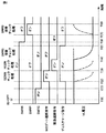
たとえば、図2に示すように、時間T(0)にて、イグニッション信号IG−OFFが入力された場合、HV−ECU350は、時間T(1)にて、リレーSMRGをオフした後に、時間T(2)以降において、SDWNチェック処理、HSDN処理、SMRG溶着チェック処理およびSMRB溶着チェック処理の順序で判定処理を実行する。
For example, as shown in FIG. 2, when the ignition signal IG-OFF is input at time T (0), the HV-
HV−ECU350は、時間T(2)にて、SDWNチェック処理を実行する。SDWNチェック処理は、HV−ECU350がMGECU300に対してMGゲート遮断指令SDWNとディスチャージ指令DCHGとを並行して出力して、所定期間が経過するまでVL電圧の変化を監視する処理である。なお、MGゲート遮断指令SDWNは、インバータ121,122の両方を非駆動状態にするための指令を含むものとする。MG−ECU300は、MGゲート遮断指令SDWNとディスチャージ指令DCHGとを並行して受信する場合には、MGゲート遮断指令SDWNを優先して実行する。そのため、MG−ECU300は、遮断指令SDN1,SDN2をインバータ121,122にそれぞれ出力する。
HV-
インバータ121,122におけるゲート遮断が適切に行なわれる場合には、リレーSMRGがオフ状態であるため、SDWNチェック処理の間、VL電圧は維持した状態となる。そのため、図2の実線に示すように、SDWNチェック処理の間、VL電圧が維持した状態である場合は、HV−ECU350は、MGゲート遮断指令SDWNに基づくゲート遮断が適切に行なわれていると判定する。一方、SDWNチェック処理において、図2の破線に示すように、時間T(2)以降にVL電圧が低下する場合には、HV−ECU350は、MGゲート遮断指令SDWNに基づくゲート遮断が適切に行なわれていないと判定する。
When the gates of
HV−ECU350は、時間T(3)にて、HSDNチェック処理を実行する。HSDNチェック処理は、HV−ECU350に対して緊急遮断指令HSDNとディスチャージ指令DCHG指令とを並行して出力して、所定期間が経過するまでVL電圧の変化を監視する処理である。MG−ECU300は、緊急遮断指令HSDNとディスチャージ指令DCHGとを並行して受信する場合には、緊急遮断指令HSDNを優先して実行する。そのため、MG−ECU300は、遮断指令SDN1,SDN2をインバータ121,122にそれぞれ出力する。
The HV-
インバータ121,122におけるゲート遮断が適切に行なわれる場合には、リレーSMRGがオフ状態であるため、HSDNチェック処理の間、VL電圧は維持した状態となる。そのため、図2の実線に示すように、HSDNチェック処理の間、VL電圧が維持した状態である場合は、HV−ECU350は、緊急遮断指令HSDNに基づくゲート遮断が適切に行なわれていると判定する。一方、HSDNチェック処理において、図2の破線に示すように、時間T(3)以降にVL電圧が低下する場合には、HV−ECU350は、緊急遮断指令HSDNに基づくゲート遮断が適切に行なわれていないと判定する。
When the gates in
HV−ECU350は、時間T(4)にて、SMRG溶着チェック処理を実行する。SMRG溶着チェック処理は、ディスチャージ指令DCHGを出力して、所定期間が経過するまで、あるいは、VL電圧がしきい値以下になるまでVL電圧の変化を監視する処理である。MG−ECU300は、ディスチャージ指令DCHG指令に基づいてインバータ121,122に対して制御信号PWI1,PWI2を出力して、平滑コンデンサC1,C2の残留電荷をモータジェネレータMG1,MG2によって消費する。リレーSMRGが溶着していない場合には、平滑コンデンサC1,C2の放電が適切に行なわれるため、時間の経過とともに低下していく。そのため、HV−ECU350は、図2の実線に示すように、時間T(4)以降にVL電圧が低下する場合には、リレーSMRGが溶着していないと判定する。
The HV-
一方、リレーSMRGが溶着している場合には、SMR190はオン状態となるため、VL電圧は維持される。そのため、HV−ECU350は、図2の破線に示すように、時間T(4)以降にVL電圧が維持される場合には、リレーSMRGが溶着していると判定する。
On the other hand, when relay SMRG is welded,
HV−ECU350は、時間T(5)にて、ディスチャージ指令DCHGの出力を停止し、時間T(6)にて、リレーSMRBをオフ状態にした後、時間T(7)にて、SMRB溶着チェック処理を実行する。SMRB溶着チェック処理は、リレーSMRPのみをオン状態にして、所定期間が経過するまでVL電圧の変化を監視する処理である。
HV-
リレーSMRBが溶着していない場合には、VL電圧が低下した状態で維持されるため、HV−ECU350は、図2の実線に示すように、時間T(7)以降にVL電圧が維持される場合には、リレーSMRGが溶着していないと判定する。一方、リレーSMRBが溶着している場合には、VL電圧が増加するため、HV−ECU350は、図2の破線に示すように、時間T(7)以降にVL電圧が増加する場合には、リレーSMRBが溶着していると判定する。
When relay SMRB is not welded, the VL voltage is maintained in a lowered state, so HV-
HV−ECU350は、イグニッション信号IG−OFFが入力されてから予め定められた第1時間Δt1が経過した後に判定処理を実行する。なお、HV−ECU350は、イグニッション信号IG−OFFが入力されてから第1時間Δt1が経過するまでの間にリレーSMRGをオフ状態にする。
The HV-
しかしながら、モータジェネレータMG1とエンジン220とが機械的に連結されている車両100においては、車両100のシステムの停止が指示された後に、エンジン220の気筒内の圧力によって出力軸が回転する場合がある。エンジン220の出力軸が回転することによりモータジェネレータMG1においては逆起電力が発生する。その結果、VL電圧が変動する場合があり、誤判定を防止するため判定処理が中止されることとなる。そのため、停止機能の異常の有無を適切なタイミングで判定することができない場合がある。
However, in
そこで、本実施の形態においては、HV−ECU350が、車両100のシステムの停止指示を受けた後にエンジン220の出力軸が回転することによって判定処理を中止した場合には、次回の判定処理の実行を、中止した判定処理の実行よりも遅らせる点を特徴とする。
Therefore, in the present embodiment, when the HV-
このようにすると、停止指示を受けた後にエンジン220の出力軸の回転変動が発生しても、次回の判定処理の実行を遅らせることにより、回転変動の発生が終了するタイミングで判定処理を実行することができる。そのため、エンジン220の出力軸の回転変動による影響を受けることなく判定処理を正常に完了させることができる。
In this way, even if the rotation fluctuation of the output shaft of the
図3に、本実施の形態に係る車両100に搭載されたHV−ECU350の機能ブロック図を示す。HV−ECU350は、IG−OFF判定部102と、未完了フラグ判定部104と、待機処理部106と、判定処理部108と、不可条件判定部110と、正常完了判定部112とを含む。なお、これらの構成は、プログラム等のソフトウェアにより実現されてもよいし、ハードウェアにより実現されてもよい。
FIG. 3 shows a functional block diagram of HV-
IG−OFF判定部102は、イグニッション信号IG−OFFが入力されたか否かを判定する。IG−OFF判定部102は、たとえば、イグニッション信号IG−OFFが入力された場合には、IG−OFF判定フラグをオン状態にしてもよい。
The IG-
未完了フラグ判定部104は、前回のIG−OFF時の判定処理が正常に完了せずに中止されたことを示す未完了フラグがオン状態であるか否かを判定する。なお、未完了フラグは、後述する正常完了判定部112によって判定処理が正常に完了していないと判定された場合にオン状態され、判定処理が正常に完了したと判定された場合には、オフ状態にされる。
The incomplete
待機処理部106は、未完了フラグ判定部104によって未完了フラグがオン状態であると判定された場合に、待機処理を実行する。待機処理は、イグニッション信号IG−OFFが入力されてから第1時間Δt1が経過したときに、さらに予め定められた第2時間Δt2が経過するまで判定処理の開始を待機する処理である。第2時間は、たとえば、イグニッション信号IG−OFFの入力により停止指示を受けた後にエンジン220の出力軸が回転したとしても、判定処理の実行が、モータジェネレータMG1の回転速度の大きさが予め定められた値よりも小さくなる時点以降となるように設定される。第2時間は、たとえば、実験等によって、適合される。
The
判定処理部108は、未完了フラグがオフ状態である場合には、イグニッション信号IG−OFFが入力されてから第1時間Δt1が経過したときに判定処理を実行する。判定処理の具体的な内容については上述したとおりであるため、その詳細な説明は繰り返さない。
When the incomplete flag is in the off state, the
判定処理部108は、未完了フラグがオン状態である場合には、イグニッション信号IG−OFFが入力されてから第1時間Δt1が経過したときに、待機処理が実行されるため、さらに第2時間Δt2が経過するまで待機した後に判定処理を実行する。
When the incomplete flag is in the ON state, the
また、判定処理部108は、後述する不可条件判定部110によって不可条件が成立すると判定される場合には実行中の判定処理を中止する。判定処理部108は、たとえば、判定処理の実行中に、後述する不可判定フラグがオン状態となる場合に、判定処理を中止する。
In addition, the
不可条件判定部110は、判定処理の実行中に、判定処理の実行を不可とする不可条件が成立するか否かを判定する。不可条件は、たとえば、判定処理の実行中に、モータジェネレータMG1の回転速度が予め定められた値以上となるという条件を含む。不可条件判定部110は、たとえば、MG−ECU300からのモータジェネレータMG1の回転角θ1を受信してモータジェネレータMG1の回転速度を算出し、算出された回転速度が予め定められた値以上であるか否かを判定してもよいし、あるいは、MG−ECU300において算出されたモータジェネレータMG1の回転速度を受信して、受信された回転速度が予め定められた値以上であるか否かを判定してもよい。不可条件判定部110は、たとえば、不可条件が成立する場合には、不可判定フラグをオン状態にする。
The unconditional
正常完了判定部112は、判定処理の実行中に不可条件が成立する場合には、判定処理が正常に完了していないと判定し、未完了フラグをオン状態にする。正常完了判定部112は、不可条件が成立することなく判定処理が完了した場合には、判定処理が正常に完了したと判定し、未完了フラグがオン状態であれば、オフ状態にする。
The normal
図4を参照して、本実施の形態に係る車両100に搭載されたHV−ECU350で実行される制御処理について説明する。
With reference to FIG. 4, a control process executed by HV-
ステップ(以下、ステップをSと記載する)100にて、HV−ECU350は、イグニッション信号IG−OFFが入力されたか否かを判定する。イグニッション信号IG−OFFが入力されたと判定された場合(S100にてYES)、処理はS102に移される。もしそうでない場合(S100にてNO)、この処理は終了する。
In step (hereinafter referred to as S) 100, HV-
S102にて、HV−ECU350は、未完了フラグがオン状態であるか否かを判定する。未完了フラグがオン状態であると判定される場合(S102にてYES)、処理はS104に移される。もしそうでない場合(102にてNO)、処理はS106に移される。
In S102, HV-
S104にて、HV−ECU350は、待機処理を実行する。S106にて、HV−ECU350は、判定処理を実行する。待機処理および判定処理については上述したとおりであるため、その詳細な説明は繰り返さない。
In S104, HV-
S108にて、HV−ECU350は、不可条件が成立するか否かを判定する。不可条件が成立する場合(S108にてYES)、処理はS110に移される。もしそうでない場合(S108にてNO)、処理はS114に移される。
In S108, HV-
S110にて、HV−ECU350は、判定処理を中止する。S112にて、HV−ECU350は、未完了フラグをオン状態にする。S114にて、HV−ECU350は、判定処理が終了したか否かを判定する。HV−ECU350は、判定処理を中止した場合や、最後のSMRB溶着チェック処理が完了した場合に、判定処理が終了したと判定する。判定処理が終了した場合(S114にてYES)、処理はS116に移される。もしそうでない場合(S114にてNO)、処理はS108に戻される。
In S110, HV-
S116にて、HV−ECU350は、判定処理が正常に完了したか否かを判定する。判定処理が正常に完了したと判定された場合(S116にてYES)、処理はS118に移される。もしそうでない場合(S116にてNO)、この処理は終了する。S118にて、HV−ECU350は、未完了フラグをオフ状態にする。
In S116, HV-
以上のような構造およびフローチャートに基づく本実施の形態に係る車両100に搭載されたHV−ECU350の動作について図5を用いて説明する。
The operation of HV-
たとえば時間T(10)にて、イグニッション信号IG−OFFが入力された場合を想定する(S100にてYES)。未完了フラグがオフ状態である場合には(S102にてNO)、時間T(10)から第1時間Δt1が経過した時間T(11)にて、判定処理が実行される(S106)。 For example, assume that ignition signal IG-OFF is input at time T (10) (YES in S100). If the incomplete flag is off (NO in S102), the determination process is executed at time T (11) when the first time Δt1 has elapsed from time T (10) (S106).
時間T(12)にて、判定処理の実行中に、モータジェネレータMG1の回転速度の大きさがしきい値よりも大きくなるなどして不可条件が成立する場合(S108にてYES)、判定処理が中止されるとともに(S110)、未完了フラグがオン状態にされる(S112)。終了した判定処理が正常に完了していないため(S114にてYES,S116にてNO)、未完了フラグはオン状態のままとなる。 At time T (12), during the determination process, if the condition is not satisfied because the rotational speed of motor generator MG1 exceeds the threshold value (YES in S108), the determination process is stopped. At the same time (S110), the incomplete flag is turned on (S112). Since the completed determination process has not been completed normally (YES in S114, NO in S116), the incomplete flag remains on.
その後に運転者のスタートスイッチの操作等によりイグニッション信号IG−ONが入力されることによって車両100のシステムが起動した場合を想定する。
Thereafter, it is assumed that the system of the
時間T(13)にて、再びイグニッション信号IG−OFFが入力された場合(S100にてYES)、未完了フラグがオン状態であるため(S102にてYES)、時間T(13)から第1時間Δt1が経過した時間T(14)にて、待機処理が実行される(S104)。待機処理は時間T(14)から第2時間Δt2が経過する時間T(15)まで実行される。時間T(14)〜時間T(15)までの間に、エンジンの気筒内の圧力によって出力軸が回転し、モータジェネレータMG1の回転速度の大きさがしきい値よりも大きくなっても、判定処理の実行中ではないため、不可条件は成立しない。 When ignition signal IG-OFF is input again at time T (13) (YES in S100), the incomplete flag is in the on state (YES in S102), so the first from time T (13) The standby process is executed at time T (14) when the time Δt1 has elapsed (S104). The standby process is executed from time T (14) to time T (15) when the second time Δt2 elapses. Even if the output shaft rotates due to the pressure in the cylinder of the engine between time T (14) and time T (15), and the magnitude of the rotational speed of motor generator MG1 becomes larger than the threshold value, the determination process Since it is not being executed, the unconditional condition is not satisfied.
時間T(15)にて、判定処理が実行される(S106)。時間T(16)にて、不可条件が成立することなく(108にてNO)、判定処理が終了する場合には(S114にてYES)、判定処理が正常に完了していると判定され(S116にてYES)、未完了フラグがオフ状態にされる(S118)。 At time T (15), determination processing is executed (S106). At time T (16), when the determination process is completed (NO in 108) without the failure condition being satisfied (NO in 108), it is determined that the determination process has been completed normally (YES in S114). If YES in S116), the incomplete flag is turned off (S118).
未完了フラグがオフ状態にされることによって、次回の判定処理は、イグニッション信号IG−OFFが入力されてから第1時間Δt1が経過したときに開始されることとなる。 Since the incomplete flag is turned off, the next determination process is started when the first time Δt1 has elapsed since the ignition signal IG-OFF was input.
以上のようにして、本実施の形態に係る車両100によると、停止指示を受けた後にエンジン220の出力軸の回転変動が発生しても、回転変動の発生が終了するタイミングで判定処理を実行することができる。そのため、エンジン220の出力軸の回転変動による影響を受けることなく判定処理を正常に完了させることができる。したがって、車両のシステムの停止が指示された後に停止処理の実行対象の電気機器の異常の有無を適切なタイミングで判定するハイブリッド車両を提供することができる。
As described above, according to
さらに、次回の判定処理が正常に完了した場合に、未完了フラグがオフ状態になるため、待機処理により遅らせた判定処理の実行を遅らせる前の状態に戻させることができる。そのため、車両のシステムの停止指示を受けてから判定処理が完了するまでの時間が長い状態が継続することを抑制することができる。 Further, when the next determination process is normally completed, the incomplete flag is turned off, so that the execution of the determination process delayed by the standby process can be returned to the state before being delayed. Therefore, it can be suppressed that a state in which the time from the reception of the stop instruction of the vehicle system to the completion of the determination process is continued is continued.
さらに、イグニッション信号IG−OFFが入力された後にエンジン220の出力軸が回転しても、判定処理の実行が、モータジェネレータMG1の回転速度の大きさが予め定められた値よりも小さくなる時点以降となるように第2時間Δt2が設定されるため、停止指示を受けた後にエンジンの出力軸の回転変動が発生しても、回転変動の発生が終了するタイミングで判定処理を実行することができる。
Further, even when the output shaft of
さらに、判定処理の実行中にモータジェネレータMG1の回転速度の大きさが予め定められた値よりも大きいという条件を含む予め定められた条件が成立する場合に、判定処理が中止されるので、エンジン220の出力軸の回転速度の大きさが予め定められた値よりも大きいことによって、モータジェネレータMG1において逆起電力が発生して判定処理を精度高く実行することができないため、判定処理を中止することにより誤判定を防止できる。
Furthermore, when the predetermined condition including the condition that the magnitude of the rotation speed of motor generator MG1 is larger than the predetermined value is satisfied during execution of the determination process, the determination process is stopped, so that the engine Since the magnitude of the rotational speed of the
以下に変形例について記載する。本実施の形態においては、図1に示すハイブリッド車両を一例として説明したが、図1に示すハイブリッド車両の構成に特に限定されるものではない。ハイブリッド車両は、少なくともエンジン220と、駆動用または発電用のモータジェネレータとを機械的に連結した構成を有していればよい。
A modification will be described below. In the present embodiment, the hybrid vehicle shown in FIG. 1 has been described as an example. However, the present invention is not particularly limited to the configuration of the hybrid vehicle shown in FIG. The hybrid vehicle may have a configuration in which at least the
本実施の形態においては、HV−ECU350は、イグニッション信号IG−OFFが入力された場合に、判定処理を実行するものを一例として説明したが、たとえば、少なくともSMR190を遮断する指示を受けた場合に判定処理を実行してもよい。HV−ECU350は、たとえば、イグニッション信号IG−OFFに代えてReady−OFF信号が入力された場合に、判定処理を実行するようにしてもよい。なお、「Ready−OFF」とは、イグニッション信号IG−OFFが入力された場合と同様に、車両100を走行不可状態にすることをいう。より具体的には、Ready−OFF信号が入力された場合、SMR190を遮断して、少なくとも走行に関連する機器(たとえば、エンジンやモータジェネレータMG1,MG2)の作動を停止状態にする。なお、「Ready−OFF」は、オーディオ等の走行に関連しない補機については作動可能な状態である点でイグニッション信号IG−OFFが入力された場合と異なる。
In the present embodiment, HV-
本実施の形態においては、HV−ECU350は、待機処理において、予め定められた第2時間Δt2が経過するまで判定処理の実行を待機し、第2時間Δt2が経過したときに判定処理を実行するものとして説明したが、たとえば、待機処理において、モータジェネレータMG1の回転速度の大きさが予め定められた値より小さくなるまで判定処理の実行を待機し、回転速度の大きさが予め定められた値よりも大きくなると判定処理を実行してもよいし、あるいは、モータジェネレータMG1の回転速度の大きさが予め定められた値よりも小さい状態が予め定められた時間継続するまで判定処理の実行を待機し、当該状態が予め定められた時間が継続したときに判定処理を実行してもよい。なお、上記した変形例は、その全部または一部を組み合わせて実施してもよい。
In the present embodiment, in the standby process, HV-
今回開示された実施の形態はすべての点で例示であって制限的なものではないと考えられるべきである。本発明の範囲は上記した説明ではなくて特許請求の範囲によって示され、特許請求の範囲と均等の意味および範囲内でのすべての変更が含まれることが意図される。 The embodiment disclosed this time should be considered as illustrative in all points and not restrictive. The scope of the present invention is defined by the terms of the claims, rather than the description above, and is intended to include any modifications within the scope and meaning equivalent to the terms of the claims.
100 車両、102 IG−OFF判定部、104 未完了フラグ判定部、106 待機処理部、108 判定処理部、110 不可条件判定部、112 正常完了判定部、120,121,122 インバータ、123,124,125 アーム、130 コンバータ、150 蓄電装置、170,180 電圧センサ、190 システムメインリレー、220 エンジン、230,240 電流センサ、250 動力分割機構、260 駆動輪、270,280 回転角センサ、300 MG−ECU、350 HV−ECU。
100 vehicle, 102 IG-OFF determination unit, 104 incomplete flag determination unit, 106 standby processing unit, 108 determination processing unit, 110 unconditional determination unit, 112 normal completion determination unit, 120, 121, 122 inverter, 123, 124, 125 arm, 130 converter, 150 power storage device, 170, 180 voltage sensor, 190 system main relay, 220 engine, 230, 240 current sensor, 250 power split mechanism, 260 drive wheel, 270, 280 rotation angle sensor, 300 MG-
Claims (4)
前記エンジンと機械的に連結された回転電機と、
前記回転電機との間で電力を授受する蓄電装置と、
車両のシステムの停止指示を受けた場合に前記停止指示を受けてから第1時間が経過したときに前記蓄電装置と前記回転電機との間に設けられる電気回路の停止処理が正常に行なわれたか否かを判定する判定処理を実行する制御装置とを備え、
前記制御装置は、前記停止指示を受けた後に前記エンジンの出力軸が回転することによって前記判定処理を中止した場合には、次回の前記判定処理を、前記停止指示を受けてから前記第1時間よりも長い第2時間が経過したときに実行する、ハイブリッド車両。 Engine,
A rotating electrical machine mechanically coupled to the engine;
A power storage device that exchanges power with the rotating electrical machine;
Was the electric circuit provided between the power storage device and the rotating electrical machine normally stopped when a first time has elapsed since receiving the stop instruction when receiving a stop instruction for a vehicle system? A control device that executes a determination process for determining whether or not,
The control device, the stop instruction when you stop the determination processing by the output shaft of the engine rotates after receiving the next time of the determination processing, the first after receiving the stop instruction A hybrid vehicle that is executed when a second time longer than the time has elapsed .
前記予め定められた時間は、前記停止指示を受けた後に前記エンジンの出力軸が回転した場合に、前記判定処理の実行が、前記回転電機の回転速度の大きさが予め定められた値よりも小さくなる時点以降となるように設定される、請求項1または2に記載のハイブリッド車両。 The second time is longer than the first time by a predetermined time,
The predetermined time is determined so that when the output shaft of the engine rotates after receiving the stop instruction, the execution of the determination process causes the rotational speed of the rotating electrical machine to be larger than a predetermined value. The hybrid vehicle according to claim 1, wherein the hybrid vehicle is set so as to be after the time point when it becomes smaller.
Priority Applications (1)
| Application Number | Priority Date | Filing Date | Title |
|---|---|---|---|
| JP2014145046A JP6256231B2 (en) | 2014-07-15 | 2014-07-15 | Hybrid vehicle |
Applications Claiming Priority (1)
| Application Number | Priority Date | Filing Date | Title |
|---|---|---|---|
| JP2014145046A JP6256231B2 (en) | 2014-07-15 | 2014-07-15 | Hybrid vehicle |
Publications (2)
| Publication Number | Publication Date |
|---|---|
| JP2016020172A JP2016020172A (en) | 2016-02-04 |
| JP6256231B2 true JP6256231B2 (en) | 2018-01-10 |
Family
ID=55265328
Family Applications (1)
| Application Number | Title | Priority Date | Filing Date |
|---|---|---|---|
| JP2014145046A Active JP6256231B2 (en) | 2014-07-15 | 2014-07-15 | Hybrid vehicle |
Country Status (1)
| Country | Link |
|---|---|
| JP (1) | JP6256231B2 (en) |
Families Citing this family (2)
| Publication number | Priority date | Publication date | Assignee | Title |
|---|---|---|---|---|
| JP7360280B2 (en) * | 2019-09-10 | 2023-10-12 | 株式会社Subaru | Brake control device |
| JP7463024B2 (en) * | 2019-11-29 | 2024-04-08 | ダイハツ工業株式会社 | Control System |
Family Cites Families (4)
| Publication number | Priority date | Publication date | Assignee | Title |
|---|---|---|---|---|
| US7544151B2 (en) * | 2006-09-13 | 2009-06-09 | Gm Global Technology Operations, Inc. | Method and apparatus to monitor operation of an auxiliary hydraulic pump in a transmission |
| JP4985873B2 (en) * | 2009-04-23 | 2012-07-25 | トヨタ自動車株式会社 | Electric vehicle power supply system and control method thereof |
| JP2010288318A (en) * | 2009-06-09 | 2010-12-24 | Toyota Motor Corp | Inverter circuit system |
| JP2014131434A (en) * | 2012-12-28 | 2014-07-10 | Daihatsu Motor Co Ltd | Vehicular control device |
-
2014
- 2014-07-15 JP JP2014145046A patent/JP6256231B2/en active Active
Also Published As
| Publication number | Publication date |
|---|---|
| JP2016020172A (en) | 2016-02-04 |
Similar Documents
| Publication | Publication Date | Title |
|---|---|---|
| US9059652B2 (en) | Motor drive system | |
| JP5626468B2 (en) | Vehicle and vehicle control method | |
| JP6330782B2 (en) | Hybrid vehicle | |
| JP5713030B2 (en) | Electric vehicle and method for determining insulation state of electric vehicle | |
| JP2009201194A (en) | Device and method for detecting abnormal condition of rotary electric machine | |
| US20090195199A1 (en) | Motor drive device | |
| JP5454676B2 (en) | Motor control device | |
| JP5287705B2 (en) | VEHICLE DRIVE DEVICE AND ITS CONTROL METHOD | |
| US10053086B2 (en) | Hybrid vehicle | |
| JP2008141868A (en) | Motor system | |
| JP5928326B2 (en) | Electric vehicle and control method of electric vehicle | |
| JP2017159773A (en) | Hybrid vehicle | |
| JP2008013119A (en) | Power output device of vehicle and its control method | |
| JP2009071901A (en) | Charging control system of power storage mechanism and fault detecting method thereof | |
| JP2009171644A (en) | Power supply unit of vehicle and its control method | |
| JP4905204B2 (en) | Load drive device | |
| JP5696589B2 (en) | Vehicle and vehicle control method | |
| JP2009189153A (en) | Electric vehicle and abnormal portion identifying method for electric vehicle | |
| JP6256231B2 (en) | Hybrid vehicle | |
| JP2012187959A (en) | Hybrid vehicle | |
| JP5958373B2 (en) | vehicle | |
| JP2017047846A (en) | Hybrid vehicle | |
| JP2014147161A (en) | Vehicle | |
| JP2017061186A (en) | Hybrid vehicle | |
| JP2009291037A (en) | Electric vehicle and fault detecting method for electric vehicle |
Legal Events
| Date | Code | Title | Description |
|---|---|---|---|
| A621 | Written request for application examination |
Free format text: JAPANESE INTERMEDIATE CODE: A621 Effective date: 20161221 |
|
| A977 | Report on retrieval |
Free format text: JAPANESE INTERMEDIATE CODE: A971007 Effective date: 20170804 |
|
| A131 | Notification of reasons for refusal |
Free format text: JAPANESE INTERMEDIATE CODE: A131 Effective date: 20170822 |
|
| A521 | Written amendment |
Free format text: JAPANESE INTERMEDIATE CODE: A523 Effective date: 20171017 |
|
| TRDD | Decision of grant or rejection written | ||
| A01 | Written decision to grant a patent or to grant a registration (utility model) |
Free format text: JAPANESE INTERMEDIATE CODE: A01 Effective date: 20171107 |
|
| A61 | First payment of annual fees (during grant procedure) |
Free format text: JAPANESE INTERMEDIATE CODE: A61 Effective date: 20171120 |
|
| R151 | Written notification of patent or utility model registration |
Ref document number: 6256231 Country of ref document: JP Free format text: JAPANESE INTERMEDIATE CODE: R151 |