JP6255688B2 - Support member, assembly, and information processing apparatus - Google Patents
Support member, assembly, and information processing apparatus Download PDFInfo
- Publication number
- JP6255688B2 JP6255688B2 JP2013066495A JP2013066495A JP6255688B2 JP 6255688 B2 JP6255688 B2 JP 6255688B2 JP 2013066495 A JP2013066495 A JP 2013066495A JP 2013066495 A JP2013066495 A JP 2013066495A JP 6255688 B2 JP6255688 B2 JP 6255688B2
- Authority
- JP
- Japan
- Prior art keywords
- support member
- fixing
- positioning
- chassis
- engagement
- Prior art date
- Legal status (The legal status is an assumption and is not a legal conclusion. Google has not performed a legal analysis and makes no representation as to the accuracy of the status listed.)
- Expired - Fee Related
Links
Images


Landscapes
- Mounting Of Printed Circuit Boards And The Like (AREA)
Description
本願の開示する技術は、支持部材、組立体及び情報処理装置に関する。 The technology disclosed in the present application relates to a support member, an assembly, and an information processing apparatus.
第1のユニットに第1のコネクタを固定し、第2にユニットに第2のコネクタを仮係止し、ユニット連結後に、第2のコネクタを第2のユニットから離脱させて第1のコネクタと接続する技術がある(たとえば、特許文献1参照)。 The first connector is fixed to the first unit, the second connector is temporarily locked to the second unit, and after the units are connected, the second connector is detached from the second unit and There is a technique for connection (see, for example, Patent Document 1).
支持部材を、固定先部材に固定した構造において、この構造から、支持部材を用いて被支持部時を支持する作業を行う際に、作業工程が少ないことが望まれる。 In the structure in which the support member is fixed to the fixing member, it is desired that the number of work steps is small when performing the work of supporting the supported portion using the support member.
本願の開示技術は、支持部材を、固定先部材に固定した構造から、実際に支持部材を用いて被支持部時を支持する作業を行う際に、作業工程を少なくすることが目的である。 The disclosed technology of the present application is intended to reduce the number of work steps when performing a work of supporting the supported part using the support member from the structure in which the support member is fixed to the fixing member.
本願の開示する技術では、支持部材を、被支持部材を支持する位置で位置決め部により固定先部材に位置決めすると共に、固定部により固定先部材に固定する。 In the technique disclosed in the present application, the support member is positioned on the fixing destination member by the positioning portion at a position where the supported member is supported, and is fixed to the fixing destination member by the fixing portion.
本願の開示する技術によれば、支持部材を、固定先部材に固定した構造から、実際に支持部材を用いて被支持部時を支持する作業を行う際に、作業工程を少なくすることが可能である。 According to the technique disclosed in the present application, it is possible to reduce the number of work steps when performing the work of supporting the supported portion using the support member from the structure in which the support member is fixed to the fixing member. It is.
第1実施形態について、図面に基づいて詳細に説明する。 1st Embodiment is described in detail based on drawing.
図1には、第1実施形態の支持部材12が示されている。また、図2には、支持部材12をシャーシ14に固定した状態の組立体16が部分的に示されている。シャーシ14は、固定先部材の一例である。さらに、図3には、支持部材12を用いて、基板本体18にヒートシンク20を取り付けた基板30を有するコンピュータ22が背面側から示されている。コンピュータ22は、情報処理装置の一例である。
FIG. 1 shows a
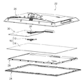
図4に示されるように、コンピュータ22は、フロントカバー24とリヤカバー26とを有している。フロントカバー24とリヤカバー26との間には、フロントカバー24側から順に、ディスプレイ28、シャーシ14、基板30が配置されて所定位置に取り付けられている。
As shown in FIG. 4, the
図10A及び図10Bにも示されるように、基板本体18には、ソケット32を介して、CPU等の素子34が実装される。そして、素子34には、基板本体18の反対面に、放熱用のヒートシンク20が配置される。支持部材12は、基板本体18にヒートシンク20を取り付けるにあたって、ヒートシンク20との間に、基板本体18、ソケット32及び素子34を挟むように配置される。そして、取り付けネジ36が、ヒートシンク20及び基板本体18に挿通され、支持部材12の雌ネジ38(図10B参照)にねじ込まれ、ヒートシンク20が基板本体18に固定される。支持部材12は、ヒートシンク20が取り付けられた基板本体18をヒートシンク20の反対側から支持することで、基板本体18の撓みを抑制している。本実施形態では、基板本体18は支持部材の一例となっている。
As also shown in FIGS. 10A and 10B, an
図1及び図2に示されるように、支持部材12は、支持本体部40を有している。図示の例では、支持本体部40は平面視(図2に示す向き)で四角形の枠状に形成されている。支持本体部40は、基板本体18に面接触し、基板本体18の撓みを抑制する部位である。以下では便宜的に、支持本体部40における4つの辺を、一方の対向辺42Aの組と、他方の対向辺42Bの組に分けて説明する。
As shown in FIGS. 1 and 2, the
支持本体部40の外縁からは、複数本(図示の例では3本)の腕部44が延出されている。それぞれの腕部44の先端部分には、後述する位置決め凸部48と同方向に向けて突出された案内凸部45が形成されている。これに対し、シャーシ14には、それぞれの案内凸部45に対応する案内長孔47が形成されている。支持部材12をシャーシ14に固定するときに、案内凸部45を案内長孔47に収容し、案内長孔47の長手方向にスライドさせることが可能である。
A plurality of (three in the illustrated example)
案内凸部45のそれぞれには、雌ネジ38が形成されている。ヒートシンク20側から基板本体18に挿通された取り付けネジ36が雌ネジ38にねじ込まれ、ヒートシンク20が基板本体18に取り付けられる。
A
支持本体部40における一方の対向辺42Aのそれぞれには、略U時状の切り欠きが形成されており、この切り欠きの内側に位置決めバネ片46が形成されている。位置決めバネ片46は板バネ状に撓み変形する。
A substantially U-shaped notch is formed in each of the
位置決めバネ片46の先端には、円錐台状に突出された位置決め凸部48が形成されている。位置決め凸部48の突出方向は、シャーシ14に支持部材12を固定するときにシャーシ14に向かう方向である。また、この方向は、基板本体18に支持部材12を用いてヒートシンク20を取り付けた状態で基板本体18から離間する方向でもある。
At the tip of the
図5に詳細に示されるように、シャーシ14には位置決め孔部50が形成されている。位置決め孔部50は、支持部材12がシャーシ14に対し所定位置となったとき、位置決め凸部48のそれぞれが嵌合する。これにより、支持部材12がシャーシ14に対し位置決めされる。この所定位置とは、基板本体18にヒートシンク20を取り付けた状態で支持部材12が基板本体18を支持する位置である。換言すれば、この支持位置は、支持部材12が、他の部材を支持するという観点で本来的な位置である。
As shown in detail in FIG. 5, a
なお、図示の例では、2つの位置決め孔部50のうち、一方の位置決め孔部50Aは平面視で真円状とし、高い位置決め精度が得られるようになっている。これに対し、他方の位置決め孔部50Bは長円状であり、支持部材12とシャーシ14との寸法誤差を吸収できるようになっている。
In the illustrated example, of the two
支持本体部40における他方の対向辺42Bのそれぞれには、略U時状の切り欠きが形成されており、この切り欠きの内側に固定バネ片52が形成されている。図8A、図9A及び図10Aに示されるように、固定バネ片52は板バネ状に撓み変形する。
A substantially U-shaped notch is formed in each of the other opposing
固定バネ片52の先端側にはさらに、固定バネ片52の延出方向と直交する方向に向けて係合部54が延出され、係合部54の反対方向には被押圧部56が延出されている。
An engaging
係合部54の延出方向及び位置は、図7Aから分かるように、支持部材12をシャーシ14に固定するときに、シャーシ14に形成された固定孔部58に挿入される方向及び位置である。組立体16としては、シャーシ14と、係合部54が固定孔部58に係合することでシャーシ14に固定された支持部材12を有する構造である。
As can be seen from FIG. 7A, the extending direction and the position of the engaging
固定バネ片52が撓み変形することで、係合部54は、固定孔部58に係合する係合位置(図7A参照)と、係合解除された係合解除位置(図10A参照)との間を移動する。
When the fixed
係合部54の先端側にはテーパー面54Tが形成され、その反対側には係合面54Kが形成されている。これに対し、シャーシ14には、固定孔部58が形成されている。係合面54Kが固定孔部58の縁部に、支持本体部40の反対側から係合することで、支持部材12がシャーシ14に固定される。
A
なお、固定孔部58に係合部54を係合させるときに、テーパー面54Tが固定孔部58の縁部に当たった場合には、固定バネ片52が僅かに撓みつつ、係合部54の先端側が固定孔部58に入るようになっている。
When the
被押圧部56は、図8A、図9A及び図10Aに詳細に示されるように、支持部材12によって、ヒートシンク20を基板本体18に取り付ける時に、基板本体18に押圧されて、固定バネ片52の撓みを大きくする位置に形成されている。このように固定バネ片52の撓みが大きくなると、係合部は係合解除位置へ移動し、固定孔部58への係合が解除される。
As shown in detail in FIGS. 8A, 9A, and 10A, the pressed
次に、本実施形態の作用を説明する。 Next, the operation of this embodiment will be described.
図4に示されるように、支持部材12とシャーシ14とは別体で形成されている。本寺家では、図7A及び図7Bに示されるように、位置決め凸部48を位置決め孔部50に嵌合させて位置決めした状態で、係合部54を固定孔部58の縁部に係合させることができる。これにより、シャーシ14と支持部材12とを固定し、組立体16として一体的に取り扱うことができる。たとえば、コンピュータ22の組立工場へ、シャーシ14と支持部材12とを一体で運ぶことが可能である。
As shown in FIG. 4, the
しかも、シャーシ14と支持部材12との固定に、固定用の部材(たとえば固定用の粘着テープ)を用いて固定する必要がないので、作業工数が少なくなると共に、低コスト化を図ることが可能である。
In addition, since it is not necessary to fix the
さらに、シャーシ14と支持部材12とを一体で輸送できるので、シャーシ14と支持部材が別体の構造と比較して、輸送コストも低減できる。
Furthermore, since the
なお、シャーシ14に支持部材12を固定するときには、図6に示されるように、まず、案内凸部45を案内長孔47に収容する。次いで、矢印S1方向に支持部材12をスライドさせることで、シャーシ14に支持部材12を固定できる。位置決め凸部48が位置決め孔部50に収容されていない状態では、位置決めバネ片46がシャーシ14の反対側に撓んでいるが、位置決め凸部48が位置決め孔部50に収容されると、この撓みは解消される。
When the
コンピュータ22を製造する場合は、図8A及び図8Bに示されるように、シャーシ14に固定された支持部材12を用いて、取り付けネジ36を、ヒートシンク20側から基板本体18に挿通し、支持部材12の雌ネジ38にねじ込む。支持部材12は、基板本体18にヒートシンク20を取り付けた状態で基板本体18を支持する位置で、シャーシ14に固定されている。このため、支持部材12を移動させる工程が不要であり、作業工数が少なくなる。
When the
しかも、上記した固定用の部材を用いていないので、支持部材12を用いて基板本体18を支持した状態で固定用の部材を除去する必要もない。固定用の部材を廃却する工数やコストも削減できる。
In addition, since the fixing member described above is not used, it is not necessary to remove the fixing member while supporting the
さらに取り付けネジ36をねじ込んでいくと、基板本体18と支持部材12とが相対的に接近する。被押圧部56が基板本体18に押されて固定バネ片52が撓むので、係合部54が係合位置から係合解除位置へ向かって移動する。
As the
図9A及び図9Bに詳細に示されるように、基板本体18と支持部材12とが接触すると、基板本体18が支持部材12で支持され、基板本体18にヒートシンク20が取り付けられた状態になる。コンピュータ22としても、組立工程において、支持部材12をシャーシ14から取り外し足り、移動させたりする工程が不要であり、組立時の作業工数が少なくなる。
As shown in detail in FIGS. 9A and 9B, when the
また、基板本体18と支持部材12とが接触した状態で、係合部54は係合解除位置に至り、固定孔部58への係合が解除される。したがって、図10A及び図10Bに示されるように、基板本体18、ヒートシンク20及び支持部材12(これらは取り付けネジ36により一体的に取り付けられている)を、シャーシ14から取り外すことが可能になる。たとえば、コンピュータ22内から基板30を取り外す場合に、基板30はシャーシ14から固定解除されているので、取り外し作業が容易である。
In addition, in a state where the
特に、本実施形態では、基板本体18と支持部材12とが接触した状態で、被押圧部56が基板本体18に押されて、係合部54が係合解除位置に至る。係合部54の固定孔部58への係合を解除させるための操作が不要であるので、基板30をコンピュータ22から取り外す際の作業性に優れる。
In particular, in the present embodiment, the pressed
また、係合部54は、係合位置と係合解除位置とを移動可能とされた部位であるので、係合解除にあたって過度の解除力が不要であり、係合部54の係合解除時の破損も抑制できる。
Further, since the engaging
しかも、基板30をコンピュータ22内から取り外した状態で、素子34にヒートシンク20が接触した状態が維持されている。ヒートシンク20を素子34から分離してしまうと、再度組み付ける際にグリス等を接触面に塗布する必要が生じるが、本実施形態ではグリス塗布の必要がなく、作業性に優れる。
In addition, the
なお、上記では、被押圧部56が基板本体18に押されることで、係合部54が係合位置から係合解除位置へ移動する構造を挙げている。しかしながら、たとえば、基板本体18の被押圧部56対応部位に孔部が形成されている構造では、基板本体18が被押圧部56を押圧することはない。このような場合には、作業者が工具等を用いて被押圧部56を押圧して固定バネ片52を撓ませ、係合部54を係合位置から係合解除位置へ移動させればよい。
In the above description, the structure in which the engaging
上記では、固定部の例として、シャーシ14の固定孔部58に縁部に係合する係合部54を挙げているが、固定部としては、係合部54に限定されない。たとえば、固定バネ片52の先端部に、シャーシ14の一部と対向する面(対向面)を形成し、対向面とシャーシ14の対向部分とを両面接着テープ等で接着してもよい。この場合、両面接着テープの接着解除には、対向面が離間するように、固定バネ片52を撓ませればよい。また、接着解除後も両面接着テープがシャーシ14又は支持部材12のいずれかに接着したまま残っていれば、廃却は不要である。ただし、この構造では両面接着テープが必要となる。また、被押圧部56が基板本体18に押圧されたときの固定バネ片52の動きを用いて、接着を解除することが、両面接着テープの位置等によっては難しい場合もある。上記実施形態のように、固定部として係合部54を用いると、部品点数が増加せず、また、被押圧部56が基板本体18に押圧されたときの、確実な係合解除(固定解除)を実現可能である。
In the above description, as an example of the fixing portion, the engaging
また、上記では、係合部54(固定部)を、支持本体部40から片持ち状に延出した固定バネ片52の設けた例を挙げているが、たとえば、支持本体部40に直接、係合部54を形成してもよい。上記のように、固定バネ片52の先端に係合部54を形成すると、固定バネ片52のバネ力を用いて係合部54を固定孔部58の縁部へ係合させることができ、より確実な係合か可能となる。また、固定バネ片52の撓みを用いて係合解除することも可能となる。
In the above description, the engaging portion 54 (fixed portion) is provided with the fixed
加えて、シャーシ14(固定先部材)としても、固定孔部58を形成する簡単な構造で、係合部54(固定部)を係合させて、支持部材12をシャーシ14に固定できる。
In addition, the
位置決め部として、上記では、位置決め凸部48を挙げているが、位置決め部は位置決め凸部48に限定されない。たとえば、支持部材12に複数の壁を形成し、この壁を、シャーシ14の一部に突き当てることで支持部材12をシャーシ14に位置決めする構造でもよい。上記のように、位置決め部として位置決め凸部48を形成すると、簡単な構造では、シャーシ14の位置決め孔部50に位置決め凸部48に嵌合させて、支持部材12をシャーシ14に位置決めすることが可能である。
In the above description, the positioning
また、上記では、位置決め凸部48(位置決め部)を、支持本体部40から片持ち状に延出した位置決めバネ片46の設けた例を挙げているが、たとえば、支持本体部40に直接、位置決め凸部48を形成してもよい。上記のように、位置決めバネ片46の先端に位置決め凸部48を形成すると、位置決めバネ片46のバネ力を用いて位置決め凸部48を位置決め孔部50に嵌合させることができ、より確実な位置決めか可能となる。
In the above example, the positioning protrusion 48 (positioning portion) is provided with the
加えて、シャーシ14(固定先部材)としても、位置決め孔部50を形成する簡単な構造で、位置決め孔部50(位置決め部)を嵌合させて、支持部材12をシャーシ14に位置決めできる。
In addition, as the chassis 14 (fixed tip member), the
上記では、支持部材の例として、基板本体18とヒートシンク20との間に素子34を挟み込んだ状態で基板本体18を支持する構造の支持部材12を挙げたが、支持部材としてはこれに限定されない。たとえば、基板本体18にコネクタ等の接続用部材を取り付ける構造において、接続用部材の取り付け部分の反対側から基板本体18を支持する支持部材であってもよい。
In the above description, the
さらに、被支持部材としても、基板本体18に限定されない。たとえば、上記したコネクタ等の接続用部材に対する被支持部材としては、情報処理装置の筐体や、情報処理装置内部の板状部材等が被支持部材の例として挙げられる。
Further, the supported member is not limited to the
情報処理装置としても、上記では、ディスプレイ28が一体化されたコンピュータ22を挙げているが、ディスプレイが別体のコンピュータでもよい。さらに、情報処理装置としては、コンピュータに限定されず、たとえば、電子情報(映像・画像・音声データ等を含む)の処理装置や記録再生装置等でもよい。
As the information processing apparatus, the
以上、本願の開示する技術の実施形態について説明したが、本願の開示する技術は、上記に限定されるものでなく、上記以外にも、その主旨を逸脱しない範囲内において種々変形して実施可能であることは勿論である。 The embodiments of the technology disclosed in the present application have been described above. However, the technology disclosed in the present application is not limited to the above, and can be variously modified and implemented in a range not departing from the gist of the present invention. Of course.
本明細書は、以上の実施形態に関し、さらに以下の付記を開示する。
(付記1)
固定先部材に固定するための固定部と、
被支持部材を支持する位置で前記固定先部材に位置決めするための位置決め部と、
を有する支持部材。
(付記2)
前記固定部が、前記固定先部材の被係合部に係合する係合部である付記1に記載の支持部材。
(付記3)
前記係合部が、前記被係合部に係合する係合位置と被係合部から係合解除される係合解除位置との間を移動可能である付記2に記載の支持部材。
(付記4)
前記被支持部材を支持した状態で被支持部材に押圧され前記係合部を前記係合位置から前記係合解除位置へ移動させる被押圧部を有する付記3に記載の支持部材。
(付記5)
前記被支持部材を支持する支持本体部と、
前記支持本体部から片持ち状に延出され先端に前記係合部が形成された固定バネ片と、
を有する付記2〜4のいずれかに記載の支持部材。
(付記6)
前記位置決め部が、前記固定先部材の位置決め孔部に嵌合する位置決め凸部である付記1〜5のいずれかに記載の支持部材。
(付記7)
前記被支持部材を支持する支持本体部と、
前記支持本体部から片持ち状に延出され先端に前記位置決め凸部が形成された位置決めバネ片と、
を有する付記6に記載の支持部材。
(付記8)
付記1〜7のいずれかに記載の支持部材と、
前記支持部材が前記固定部により固定されると共に前記位置決め部により位置決めされた固定先部材と、
を有する組立体。
(付記9)
付記2〜5のいずれかに記載の支持部材を有する付記7に記載の組立体であって、
前記固定先部材が、前記係合部が部分的に挿通されて係合する固定孔部を有している組立体。
(付記10)
付記6又は7に記載の支持部材を有する付記8又は9に記載の組立体であって、
前記固定先部材が、前記位置決め凸部が嵌合する位置決め孔部を有している組立体。
(付記11)
付記8〜10のいずれかに記載の組立体と、
前記組立体の前記支持部材により支持された被支持部材と、
を有する情報処理装置。
(付記12)
前記被支持部材が前記支持部材に支持された状態で前記固定部による固定先部材への支持部材の固定が解除されている付記11に記載の情報処理装置。
The present specification further discloses the following supplementary notes regarding the above embodiments.
(Appendix 1)
A fixing portion for fixing to a fixing member;
A positioning portion for positioning the fixed member at a position for supporting the supported member;
A support member.
(Appendix 2)
The support member according to appendix 1, wherein the fixing portion is an engaging portion that engages with an engaged portion of the fixing destination member.
(Appendix 3)
The support member according to supplementary note 2, wherein the engagement portion is movable between an engagement position where the engagement portion engages with the engaged portion and an engagement release position where the engagement portion is released from the engagement portion.
(Appendix 4)
The support member according to appendix 3, further comprising a pressed portion that is pressed by the supported member in a state where the supported member is supported and moves the engaging portion from the engagement position to the engagement release position.
(Appendix 5)
A support main body for supporting the supported member;
A fixed spring piece extending in a cantilevered manner from the support body part and having the engagement part formed at the tip;
The support member according to any one of appendices 2 to 4, having the following.
(Appendix 6)
The support member according to any one of appendices 1 to 5, wherein the positioning portion is a positioning convex portion that fits into a positioning hole portion of the fixing destination member.
(Appendix 7)
A support main body for supporting the supported member;
A positioning spring piece that is cantilevered from the support main body and has the positioning projection formed at the tip;
The support member according to appendix 6, having
(Appendix 8)
The support member according to any one of appendices 1 to 7,
A fixing point member fixed by the fixing portion and positioned by the positioning portion;
An assembly.
(Appendix 9)
The assembly according to appendix 7, having the support member according to any one of appendices 2 to 5,
The assembly in which the fixing member has a fixing hole portion into which the engaging portion is partially inserted and engaged.
(Appendix 10)
The assembly according to appendix 8 or 9, comprising the support member according to appendix 6 or 7,
An assembly in which the fixed member has a positioning hole portion into which the positioning convex portion is fitted.
(Appendix 11)
An assembly according to any one of appendices 8 to 10,
A supported member supported by the support member of the assembly;
An information processing apparatus.
(Appendix 12)
The information processing apparatus according to appendix 11, wherein the fixing of the supporting member to the fixing member by the fixing portion is released in a state where the supported member is supported by the supporting member.
12 支持部材
14 シャーシ(固定先部材)
16 組立体
18 基板本体(被支持部材)
22 コンピュータ(情報処理装置)
40 支持本体部
46 位置決めバネ片
48 位置決め凸部(位置決め部)
50 位置決め孔部
52 固定バネ片
54 係合部(固定部)
56 被押圧部
58 固定孔部(被係合部)
12 Supporting
16
22 Computer (information processing device)
40
50
56
Claims (7)
前記固定部と異なる位置に設けられ、被支持部材を支持する位置で前記固定先部材に位置決めするための位置決め部と、
を有する支持部材。 A fixing portion for fixing to a fixing member;
A positioning portion that is provided at a position different from the fixing portion and for positioning the fixing destination member at a position that supports the supported member;
A support member.
前記支持部材が前記固定部により固定されると共に前記位置決め部により位置決めされた固定先部材と、
を有する組立体。 The support member according to any one of claims 1 to 5,
A fixing point member fixed by the fixing portion and positioned by the positioning portion;
An assembly.
前記組立体の前記支持部材により支持された被支持部材と、
を有する情報処理装置。
An assembly according to claim 6;
A supported member supported by the support member of the assembly;
An information processing apparatus.
Priority Applications (1)
| Application Number | Priority Date | Filing Date | Title |
|---|---|---|---|
| JP2013066495A JP6255688B2 (en) | 2013-03-27 | 2013-03-27 | Support member, assembly, and information processing apparatus |
Applications Claiming Priority (1)
| Application Number | Priority Date | Filing Date | Title |
|---|---|---|---|
| JP2013066495A JP6255688B2 (en) | 2013-03-27 | 2013-03-27 | Support member, assembly, and information processing apparatus |
Publications (2)
| Publication Number | Publication Date |
|---|---|
| JP2014192335A JP2014192335A (en) | 2014-10-06 |
| JP6255688B2 true JP6255688B2 (en) | 2018-01-10 |
Family
ID=51838330
Family Applications (1)
| Application Number | Title | Priority Date | Filing Date |
|---|---|---|---|
| JP2013066495A Expired - Fee Related JP6255688B2 (en) | 2013-03-27 | 2013-03-27 | Support member, assembly, and information processing apparatus |
Country Status (1)
| Country | Link |
|---|---|
| JP (1) | JP6255688B2 (en) |
Cited By (1)
| Publication number | Priority date | Publication date | Assignee | Title |
|---|---|---|---|---|
| JP7427009B2 (en) | 2019-11-08 | 2024-02-02 | 大日本除蟲菊株式会社 | Metered dose aerosol for space treatment |
Family Cites Families (2)
| Publication number | Priority date | Publication date | Assignee | Title |
|---|---|---|---|---|
| JP2002290076A (en) * | 2001-03-27 | 2002-10-04 | Densei Lambda Kk | Supporting tool for substrate and circuit arrangement having the supporting tool for substrate |
| JP2002280767A (en) * | 2002-02-18 | 2002-09-27 | Nifco Inc | Fixing metal of printed board |
-
2013
- 2013-03-27 JP JP2013066495A patent/JP6255688B2/en not_active Expired - Fee Related
Cited By (1)
| Publication number | Priority date | Publication date | Assignee | Title |
|---|---|---|---|---|
| JP7427009B2 (en) | 2019-11-08 | 2024-02-02 | 大日本除蟲菊株式会社 | Metered dose aerosol for space treatment |
Also Published As
| Publication number | Publication date |
|---|---|
| JP2014192335A (en) | 2014-10-06 |
Similar Documents
| Publication | Publication Date | Title |
|---|---|---|
| US7359189B2 (en) | Electronic device with removable module | |
| US7990736B2 (en) | Mounting apparatus for expansion card | |
| US10568207B2 (en) | Printed circuit board assembly and assembling method thereof | |
| US20140004734A1 (en) | Insertion tool for memory modules | |
| JP2008046376A (en) | Auxiliary device for releasing fall-off stopper of optical connector and printed circuit board system | |
| US20130092807A1 (en) | Mounting apparatus for storage device | |
| TW201325402A (en) | Fixing mechanism for data memory and memory module usin same | |
| US8982551B2 (en) | Electronic device and electronic module fixing structure thereof | |
| US8550671B2 (en) | Clamp structure for fixing a light bar on a base and backlight module having clamp structure | |
| US9060426B2 (en) | Securing mechanism | |
| CN102043451A (en) | Case | |
| US7399196B2 (en) | Interface card fixing member | |
| JP6255688B2 (en) | Support member, assembly, and information processing apparatus | |
| US8724310B2 (en) | Clamp assembly and method of clamping a disk drive | |
| US20150003006A1 (en) | Casing structure and electronic device using the same | |
| CN102346511A (en) | Data storage fixing device | |
| US20070236893A1 (en) | External hard disk drive rack | |
| TWI483662B (en) | Electronic apparatus and fixing structure thereof | |
| TWM498443U (en) | Detachable fixing mechanism and related electronic device | |
| CN104020824A (en) | Electronic equipment and solid state drive fixing device thereof | |
| JP6021696B2 (en) | Electronic device and fan motor holding structure | |
| US20080239653A1 (en) | Disk drive assembly with mounting bracket | |
| US20130105422A1 (en) | Fixing device for data storage device | |
| JP2019109948A (en) | Magnetic disk storage fixing apparatus | |
| TWI551209B (en) | Back plate structure and mother board assembly structure thereof |
Legal Events
| Date | Code | Title | Description |
|---|---|---|---|
| A621 | Written request for application examination |
Free format text: JAPANESE INTERMEDIATE CODE: A621 Effective date: 20151106 |
|
| A977 | Report on retrieval |
Free format text: JAPANESE INTERMEDIATE CODE: A971007 Effective date: 20160831 |
|
| A131 | Notification of reasons for refusal |
Free format text: JAPANESE INTERMEDIATE CODE: A131 Effective date: 20160906 |
|
| A521 | Written amendment |
Free format text: JAPANESE INTERMEDIATE CODE: A523 Effective date: 20161104 |
|
| A131 | Notification of reasons for refusal |
Free format text: JAPANESE INTERMEDIATE CODE: A131 Effective date: 20170314 |
|
| A521 | Written amendment |
Free format text: JAPANESE INTERMEDIATE CODE: A523 Effective date: 20170501 |
|
| TRDD | Decision of grant or rejection written | ||
| A01 | Written decision to grant a patent or to grant a registration (utility model) |
Free format text: JAPANESE INTERMEDIATE CODE: A01 Effective date: 20171107 |
|
| A61 | First payment of annual fees (during grant procedure) |
Free format text: JAPANESE INTERMEDIATE CODE: A61 Effective date: 20171120 |
|
| R150 | Certificate of patent or registration of utility model |
Ref document number: 6255688 Country of ref document: JP Free format text: JAPANESE INTERMEDIATE CODE: R150 |
|
| S111 | Request for change of ownership or part of ownership |
Free format text: JAPANESE INTERMEDIATE CODE: R313113 |
|
| R350 | Written notification of registration of transfer |
Free format text: JAPANESE INTERMEDIATE CODE: R350 |
|
| LAPS | Cancellation because of no payment of annual fees |