JP6251484B2 - LCD assembly structure for automotive meters - Google Patents
LCD assembly structure for automotive meters Download PDFInfo
- Publication number
- JP6251484B2 JP6251484B2 JP2013053878A JP2013053878A JP6251484B2 JP 6251484 B2 JP6251484 B2 JP 6251484B2 JP 2013053878 A JP2013053878 A JP 2013053878A JP 2013053878 A JP2013053878 A JP 2013053878A JP 6251484 B2 JP6251484 B2 JP 6251484B2
- Authority
- JP
- Japan
- Prior art keywords
- liquid crystal
- crystal plate
- piece
- elastic pressing
- pair
- Prior art date
- Legal status (The legal status is an assumption and is not a legal conclusion. Google has not performed a legal analysis and makes no representation as to the accuracy of the status listed.)
- Active
Links
- 239000004973 liquid crystal related substance Substances 0.000 claims description 175
- 239000000758 substrate Substances 0.000 claims description 10
- 238000010276 construction Methods 0.000 claims 1
- 210000000078 claw Anatomy 0.000 description 30
- 230000037431 insertion Effects 0.000 description 11
- 238000003780 insertion Methods 0.000 description 11
- 238000005452 bending Methods 0.000 description 6
- 239000000463 material Substances 0.000 description 2
- 230000000630 rising effect Effects 0.000 description 2
- 230000004308 accommodation Effects 0.000 description 1
- 230000007423 decrease Effects 0.000 description 1
- 230000003247 decreasing effect Effects 0.000 description 1
- 239000011521 glass Substances 0.000 description 1
- 238000010030 laminating Methods 0.000 description 1
- 230000002093 peripheral effect Effects 0.000 description 1
- 239000000565 sealant Substances 0.000 description 1
- 229920003002 synthetic resin Polymers 0.000 description 1
- 239000000057 synthetic resin Substances 0.000 description 1
- 230000009466 transformation Effects 0.000 description 1
Images


Classifications
-
- G—PHYSICS
- G02—OPTICS
- G02F—OPTICAL DEVICES OR ARRANGEMENTS FOR THE CONTROL OF LIGHT BY MODIFICATION OF THE OPTICAL PROPERTIES OF THE MEDIA OF THE ELEMENTS INVOLVED THEREIN; NON-LINEAR OPTICS; FREQUENCY-CHANGING OF LIGHT; OPTICAL LOGIC ELEMENTS; OPTICAL ANALOGUE/DIGITAL CONVERTERS
- G02F1/00—Devices or arrangements for the control of the intensity, colour, phase, polarisation or direction of light arriving from an independent light source, e.g. switching, gating or modulating; Non-linear optics
- G02F1/01—Devices or arrangements for the control of the intensity, colour, phase, polarisation or direction of light arriving from an independent light source, e.g. switching, gating or modulating; Non-linear optics for the control of the intensity, phase, polarisation or colour
- G02F1/13—Devices or arrangements for the control of the intensity, colour, phase, polarisation or direction of light arriving from an independent light source, e.g. switching, gating or modulating; Non-linear optics for the control of the intensity, phase, polarisation or colour based on liquid crystals, e.g. single liquid crystal display cells
- G02F1/133—Constructional arrangements; Operation of liquid crystal cells; Circuit arrangements
- G02F1/1333—Constructional arrangements; Manufacturing methods
- G02F1/133308—Support structures for LCD panels, e.g. frames or bezels
-
- B—PERFORMING OPERATIONS; TRANSPORTING
- B60—VEHICLES IN GENERAL
- B60K—ARRANGEMENT OR MOUNTING OF PROPULSION UNITS OR OF TRANSMISSIONS IN VEHICLES; ARRANGEMENT OR MOUNTING OF PLURAL DIVERSE PRIME-MOVERS IN VEHICLES; AUXILIARY DRIVES FOR VEHICLES; INSTRUMENTATION OR DASHBOARDS FOR VEHICLES; ARRANGEMENTS IN CONNECTION WITH COOLING, AIR INTAKE, GAS EXHAUST OR FUEL SUPPLY OF PROPULSION UNITS IN VEHICLES
- B60K35/00—Arrangement of adaptations of instruments
-
- B60K35/215—
-
- B60K35/22—
-
- B60K35/50—
-
- B60K35/60—
-
- B—PERFORMING OPERATIONS; TRANSPORTING
- B60—VEHICLES IN GENERAL
- B60K—ARRANGEMENT OR MOUNTING OF PROPULSION UNITS OR OF TRANSMISSIONS IN VEHICLES; ARRANGEMENT OR MOUNTING OF PLURAL DIVERSE PRIME-MOVERS IN VEHICLES; AUXILIARY DRIVES FOR VEHICLES; INSTRUMENTATION OR DASHBOARDS FOR VEHICLES; ARRANGEMENTS IN CONNECTION WITH COOLING, AIR INTAKE, GAS EXHAUST OR FUEL SUPPLY OF PROPULSION UNITS IN VEHICLES
- B60K37/00—Dashboards
-
- B60K2360/1523—
-
- B60K2360/42—
-
- B60K2360/816—
-
- B60K2360/96—
-
- G—PHYSICS
- G02—OPTICS
- G02F—OPTICAL DEVICES OR ARRANGEMENTS FOR THE CONTROL OF LIGHT BY MODIFICATION OF THE OPTICAL PROPERTIES OF THE MEDIA OF THE ELEMENTS INVOLVED THEREIN; NON-LINEAR OPTICS; FREQUENCY-CHANGING OF LIGHT; OPTICAL LOGIC ELEMENTS; OPTICAL ANALOGUE/DIGITAL CONVERTERS
- G02F1/00—Devices or arrangements for the control of the intensity, colour, phase, polarisation or direction of light arriving from an independent light source, e.g. switching, gating or modulating; Non-linear optics
- G02F1/01—Devices or arrangements for the control of the intensity, colour, phase, polarisation or direction of light arriving from an independent light source, e.g. switching, gating or modulating; Non-linear optics for the control of the intensity, phase, polarisation or colour
- G02F1/13—Devices or arrangements for the control of the intensity, colour, phase, polarisation or direction of light arriving from an independent light source, e.g. switching, gating or modulating; Non-linear optics for the control of the intensity, phase, polarisation or colour based on liquid crystals, e.g. single liquid crystal display cells
- G02F1/133—Constructional arrangements; Operation of liquid crystal cells; Circuit arrangements
- G02F1/1333—Constructional arrangements; Manufacturing methods
- G02F1/133308—Support structures for LCD panels, e.g. frames or bezels
- G02F1/133314—Back frames
Description
本発明は、自動車用メータのLCD組付構造に関する。 The present invention relates to an LCD assembly structure for an automobile meter.
自動車用メータには、走行距離などの各種情報を表示するための液晶板(LCD)が取り付けられる場合がある(例えば、特許文献1及び2参照)。
図6に示すように、従来の液晶ホルダ501には液晶収容凹部503が形成され、その周壁505には複数の弾性係止爪507が突設されている。液晶板509は、下面側に輝度上昇フィルム511(BEF)、黒縁シール材513、導光板515を積層して配置され、液晶収容凹部503に組み込まれる。組み込まれた液晶板509は、X方向位置決め部517、Y方向位置決め部519によって位置決めされ、液晶板表面521を弾性係止爪507が係止することで、液晶ホルダ501から浮上する方向の移動が固定される。液晶ホルダ501には配線板収納スペース523が形成され、配線板収納スペース523に収納された配線板525が、配線板固定爪527によって固定される。液晶板509は基板部529を有し、基板部529にはフラットケーブル531(FPC)が接続される。フラットケーブル531は配線板525に接続され、配線板525の回路を介して配線板コネクタ533に接続される。
A car meter may be provided with a liquid crystal plate (LCD) for displaying various information such as a travel distance (for example, see Patent Documents 1 and 2).
As shown in FIG. 6, a conventional
しかしながら、上記した従来の自動車用メータのLCD組付構造では、液晶収容凹部503からの液晶板509の浮上を阻止するために弾性係止爪507を用いていたため、図7に示すように、液晶板表面521より上方の固定部突出寸法Dを小さくするのに限界があった。弾性係止爪507の場合、爪部535が先端に向かって薄肉となるため、固定部突出寸法Dを小さくすれば、係止強度が低下し、固定構造の信頼性を低下させることになる。また、弾性係止爪507は、液晶板509を組付ける際に、爪部535の先端が液晶板509の外形より外に一旦退避する必要があるため、爪部535と反対の背面側に撓み空間が必要である。
従って、従来の弾性係止爪507によるLCD組付構造では、液晶板509を固定するための高さ寸法と弾性係止爪507のための撓み空間が必要となり、液晶板509の外形形状より大きな一定の組付けスペースが必要となるという問題があった。
However, in the above-described conventional LCD assembly structure for an automobile meter, the
Therefore, in the conventional LCD assembly structure with the
本発明は上記状況に鑑みてなされたもので、その目的は、液晶板を容易な組付作業でガタツキなく固定でき、しかも、組付けスペースを小さくできる自動車用メータのLCD組付構造を提供することにある。 The present invention has been made in view of the above circumstances, and an object of the present invention is to provide an LCD meter mounting structure for an automobile meter that can fix a liquid crystal plate without any looseness by an easy assembling operation and can reduce the assembling space. There is.
本発明に係る上記目的は、下記構成により達成される。
(1) 方形状の液晶板と、前記液晶板と略相似形状の方形状で液晶ホルダに凹設されて前記液晶板を収容する液晶収容凹部と、前記液晶収容凹部の底壁に直接突設されて前記液晶板の裏面を前記底壁から離反方向に付勢する底壁弾性押圧片と、前記液晶収容凹部の隣接する一対の隅部に前記液晶ホルダのホルダ表面と平行な同一平面に延出されて前記液晶板の表面に当接する隅部固定片と、前記隅部固定片と対向する一対の隅部に前記液晶ホルダのホルダ表面と平行な同一平面に延出されて前記液晶板の一辺側から延出している基板部の表面に当接する延出片と、一対の前記隅部固定片の間の前記液晶収容凹部に直接配設されて前記液晶板の一端面を前記延出片に向かって押圧付勢する第1弾性押圧片と、を備え、前記延出片は、前記液晶収容凹部の深さ方向において前記隅部固定片より厚く形成されて前記液晶板の表面より薄い前記基板部を挟持することを特徴とする自動車用メータのLCD組付構造。
The above object of the present invention is achieved by the following configuration.
(1) A rectangular liquid crystal plate, a liquid crystal containing recess that is recessed in the liquid crystal holder and has a shape substantially similar to the liquid crystal plate, and that houses the liquid crystal plate, and projects directly from the bottom wall of the liquid crystal containing recess And a bottom wall elastic pressing piece for urging the back surface of the liquid crystal plate away from the bottom wall, and a pair of adjacent corners of the liquid crystal receiving recess extending in the same plane parallel to the holder surface of the liquid crystal holder. A corner fixing piece that is brought into contact with the surface of the liquid crystal plate, and a pair of corners facing the corner fixing piece are extended in the same plane parallel to the holder surface of the liquid crystal holder . An extending piece that abuts on the surface of the substrate portion extending from one side, and the liquid crystal receiving recess between the pair of corner fixing pieces are disposed directly on one end surface of the liquid crystal plate. A first elastic pressing piece that presses and biases the liquid crystal toward the liquid crystal. An LCD assembly structure for an automotive meter, wherein the substrate portion is formed to be thicker than the corner fixing piece and thinner than the surface of the liquid crystal plate in the depth direction of the recess .
上記(1)の構成の自動車用メータのLCD組付構造によれば、液晶板の挿入側辺部が、液晶収容凹部の隣接する一対の隅部に設けられた隅部固定片の下方へ差し入れられると、挿入側辺部が一対の隅部固定片の間に設けられている第1弾性押圧片に当接する。液晶板は、挿入側辺部が第1弾性押圧片に当接した状態で更に押し込まれて第1弾性押圧片を弾性変形させると、手元側辺部が一対の延出片の先端を越えた位置となる。この状態で手元側辺部が底壁に接近する方向に押し込まれると、底壁に設けられている底壁弾性押圧片が押下され、液晶板の表面が延出片よりも下方に配置される。液晶板は、第1弾性押圧片を弾性変形させる方向の押し込み力が減少すると、第1弾性押圧片の弾性復元力によって延出片の方向に向かって押し戻され、手元側辺部が延出片の下面側に配置される。これにより、液晶板は、液晶板の裏面が底壁弾性押圧片によって底壁から浮上する方向に押圧付勢されるとともに、液晶板の表面における四隅が隅部固定片と延出片とによって押さえられ、液晶収容凹部に挟持固定される。
このように、液晶板は、一方向の押し込み動作によって、液晶ホルダへ容易に組み付けが可能となる。また、液晶板は、厚み方向が隅部固定片及び延出片と下方の底壁弾性押圧片とによって弾性挟持されると共に、液晶板表面に沿う方向が第1弾性押圧片と延出片とによって弾性挟持され、ガタツキなく確実に固定される。そして、隅部固定片及び延出片は、ホルダ表面と平行に延出される長さを比較的大きくして係止強度を確保することで、従来の弾性係止爪の爪部に比べて肉厚を薄く形成できるので、液晶板の表面からの突出高さを小さく抑えることができる。また、第1弾性押圧片は、従来の弾性係止爪のような爪部を設ける必要がなく、爪部の先端が液晶板の外形より外に一旦退避するための大きな撓み空間を確保する必要がないので、組付けスペースを最小限とすることができる。
According to the LCD assembly structure of the automobile meter having the configuration of (1) above, the insertion side of the liquid crystal plate is inserted below the corner fixing pieces provided at the adjacent corners of the liquid crystal receiving recess. Then, the insertion side edge comes into contact with the first elastic pressing piece provided between the pair of corner fixing pieces. When the liquid crystal plate is further pushed in with the insertion side portion in contact with the first elastic pressing piece and the first elastic pressing piece is elastically deformed, the proximal side portion exceeds the tips of the pair of extending pieces. Position. In this state, when the proximal side portion is pushed in the direction approaching the bottom wall, the bottom wall elastic pressing piece provided on the bottom wall is pushed down, and the surface of the liquid crystal plate is disposed below the extending piece. . When the pushing force in the direction in which the first elastic pressing piece is elastically deformed is reduced, the liquid crystal plate is pushed back toward the extending piece by the elastic restoring force of the first elastic pressing piece, and the proximal side portion is the extending piece. It is arranged on the lower surface side. As a result, the liquid crystal plate is pressed and urged by the bottom wall elastic pressing piece in the direction of rising from the bottom wall, and the four corners on the surface of the liquid crystal plate are pressed by the corner fixing pieces and the extension pieces. And is held and fixed in the liquid crystal receiving recess.
Thus, the liquid crystal plate can be easily assembled to the liquid crystal holder by a one-way pushing operation. The liquid crystal plate is elastically sandwiched between the corner fixing piece and the extension piece and the bottom wall elastic pressing piece in the thickness direction, and the direction along the liquid crystal plate surface is the first elastic pressing piece and the extension piece. And is securely fixed without rattling. The corner fixing pieces and the extension pieces are relatively large in length extending in parallel with the holder surface to ensure the locking strength, so that the corner fixing pieces and the extension pieces are larger than the claws of the conventional elastic locking claws. Since the thickness can be reduced, the protruding height from the surface of the liquid crystal plate can be kept small. Further, the first elastic pressing piece does not need to be provided with a claw portion like a conventional elastic locking claw, and it is necessary to secure a large bending space for the tip of the claw portion to be temporarily retracted outside the outer shape of the liquid crystal plate. Since there is no, assembly space can be minimized.
(2) 上記(1)の構成の自動車用メータのLCD組付構造であって、一対の前記隅部固定片が設けられる隅部固定片側辺部と一対の前記延出片が設けられる延出片側辺部とに挟まれる一対の挟辺部の一方側の前記液晶収容凹部には、液晶板の端面に当接する当接ボスが直接設けられ、前記一対の挟辺部の他方側の前記液晶収容凹部には、前記液晶板を前記当接ボスに向かって押圧付勢する第2弾性押圧片が直接設けられることを特徴とする自動車用メータのLCD組付構造。
(2) The automotive meter LCD assembling structure of the configuration of (1) above, wherein a corner fixed piece side side provided with a pair of the corner fixed pieces and an extension provided with a pair of the extended pieces are provided. on one side the liquid crystal concave of the pair of Kyohen portion sandwiched between the side edge portion abutting contact boss on the end surface of the liquid crystal panel is provided directly above the other side of the pair of Kyohen
上記(2)の構成の自動車用メータのLCD組付構造によれば、液晶板が液晶収容凹部に組み付けられるとき、挿入側辺部を隅部固定片の下方へ差し入れて底壁弾性押圧片を押下すると、第2弾性押圧片が外側に撓められて液晶板が押し込まれる。手元側辺部が延出片の下面側に配置されると、第2弾性押圧片の弾性復元力によって液晶板は当接ボスに押し当てられる。これにより、液晶板は、液晶板の表面に沿う方向が、第1弾性押圧片と延出片による挟持方向と、これに直交する第2弾性押圧片と当接ボスによる挟持方向とによって、より確実にガタツキなく固定される。また、第2弾性押圧片も、従来の弾性係止爪のような爪部を設ける必要がなく、爪部の先端が液晶板の外形より外に一旦退避するための大きな撓み空間を確保する必要がないので、組付けスペースを最小限とすることができる。 According to the LCD assembly structure of the automobile meter having the configuration of (2) above, when the liquid crystal plate is assembled in the liquid crystal receiving recess, the side of the insertion side is inserted below the corner fixing piece, and the bottom wall elastic pressing piece is When pressed, the second elastic pressing piece is bent outward and the liquid crystal plate is pressed. When the proximal side portion is disposed on the lower surface side of the extending piece, the liquid crystal plate is pressed against the contact boss by the elastic restoring force of the second elastic pressing piece. As a result, the liquid crystal plate has a direction along the surface of the liquid crystal plate depending on a holding direction by the first elastic pressing piece and the extending piece, and a holding direction by the second elastic pressing piece and the contact boss orthogonal to the first elastic pressing piece. It is securely fixed without rattling. Also, the second elastic pressing piece does not need to be provided with a claw portion like a conventional elastic locking claw, and it is necessary to secure a large bending space for the tip of the claw portion to be temporarily retracted from the outer shape of the liquid crystal plate. Since there is no, assembly space can be minimized.
(3) 上記(2)の構成の自動車用メータのLCD組付構造であって、前記第2弾性押圧片の起立先端には、前記液晶収容凹部の中心に向かって低くなる押込み用テーパ面が形成されることを特徴とする自動車用メータのLCD組付構造。 (3) In the automobile meter LCD assembly structure of (2) above, a push-down tapered surface that decreases toward the center of the liquid crystal housing recess is formed at the standing tip of the second elastic pressing piece. An LCD assembly structure for an automobile meter, wherein the LCD assembly structure is formed.
上記(3)の構成の自動車用メータのLCD組付構造によれば、挿入側辺部を隅部固定片の下方へ差し入れ、底壁弾性押圧片を押下する際、第2弾性押圧片の起立先端に設けられた押込み用テーパ面が液晶板の裏面によって押圧される。液晶板の裏面に押圧された第2弾性押圧片は、押込み用テーパ面に加えられる押し込み力の分力によって外側に撓められる。液晶板が組み込まれると、第2弾性押圧片が弾性復元して液晶板が当接ボスに当接される。即ち、第2弾性押圧片を別途外側に撓める作業を行わずに、液晶板がより容易に組み付け可能となる。 According to the LCD assembly structure of the automotive meter having the configuration of (3) above, when the insertion side is inserted below the corner fixing piece and the bottom wall elastic pressing piece is pressed, the second elastic pressing piece is raised. The taper surface for pressing provided at the tip is pressed by the back surface of the liquid crystal plate. The second elastic pressing piece pressed against the back surface of the liquid crystal plate is bent outward by a component of the pressing force applied to the pressing taper surface. When the liquid crystal plate is assembled, the second elastic pressing piece is elastically restored and the liquid crystal plate is brought into contact with the contact boss. That is, the liquid crystal plate can be assembled more easily without performing the work of bending the second elastic pressing piece separately outside.
本発明に係る自動車用メータのLCD組付構造によれば、液晶板を容易な組付作業でガタツキなく固定でき、しかも、組付けスペースを小さくできる。 According to the LCD assembly structure for an automobile meter according to the present invention, the liquid crystal plate can be fixed without backlash by an easy assembly operation, and the assembly space can be reduced.
以上、本発明について簡潔に説明した。更に、以下に説明される発明を実施するための形態(以下、「実施形態」という。)を添付の図面を参照して通読することにより、本発明の詳細は更に明確化されるであろう。 The present invention has been briefly described above. Further, the details of the present invention will be further clarified by reading through a mode for carrying out the invention described below (hereinafter referred to as “embodiment”) with reference to the accompanying drawings. .
以下、本発明に係る実施形態を図面を参照して説明する。
図1に示すように、本発明の一実施形態に係るLCD組付構造は、自動車用メータであるコンビネーションメータ11に好適に用いることができる。コンビネーションメータ11は、例えば車両の図示しないインストルメントパネルに取り付けられる。コンビネーションメータ11には、図1に示すように、車両の速度を指示する速度計13と、液晶板15(LCD)を用いた液晶表示装置17のマルチ表示部19と、ターンL表示部21と、ターンR表示部23と、エンジンの回転数を表示する回転計25と、シフトインジケータ27と、TRIPノブ29と、シートベルト非着用やヘッドランプ消し忘れ用等のウォーニングランプ31と、が設けられている。
Embodiments according to the present invention will be described below with reference to the drawings.
As shown in FIG. 1, the LCD assembly structure according to one embodiment of the present invention can be suitably used for a
これら速度計13、マルチ表示部19、ターンL表示部21、ターンR表示部23、回転計25、シフトインジケータ27、TRIPノブ29は、コンビネーションメータ11の図示しないメータケースに収容されている。メータケースの正面には見返し33が取り付けられ、見返し33はメータケースに収容された配線基板や駆動部などを隠す。また、メータケースの正面側には表ガラスが取り付けられている。
The
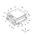
マルチ表示部19として表出する液晶表示装置17は、図2に示すように、メータケースの液晶ホルダ35に収容される。液晶ホルダ35は、合成樹脂材によりメータケースと一体成形される。
図3に示すように、液晶板15は、方形状に形成され、フラットケーブル37(FPC)が接続される基板部39が一辺側から延出している。液晶板15の下面には2枚の輝度上昇フィルム41(BEF)が積層され、輝度上昇フィルム41は縁部に設けられた取付穴43を液晶ホルダ35に設けられたBEF取付ボス45に嵌合することで位置決めされて取り付けられる。輝度上昇フィルム41が取り付けられる載置面には、図示しない導光板に貼られたプリズムシート47が配置されている。
As shown in FIG. 2, the liquid
As shown in FIG. 3, the
液晶ホルダ35には液晶収容凹部49が凹設され、液晶収容凹部49は液晶板15と略相似形状の方形状で液晶板15を収容する。液晶収容凹部49は、底壁51の中央側に導光板、プリズムシート47、輝度上昇フィルム41を収容する凹部53が形成される。即ち、底壁51は、凹部53の周囲に形成されている。底壁51には、少なくとも液晶板15が直接載置される。この他、底壁51には液晶板15と共に、輝度上昇フィルム41が載置されてもよい。
The
液晶収容凹部49の底壁51には底壁弾性押圧片55が突設され、底壁弾性押圧片55は液晶板15を底壁51から離反方向(浮上方向)に付勢する。本実施形態において、底壁弾性押圧片55は、液晶収容凹部49の平行な二辺に沿って3つが設けられている。底壁弾性押圧片55は、底壁51にコ字状の切り込みを設け、自由端側の凸部55aが底壁51から突出するように形成されている。
A bottom wall elastic pressing
液晶収容凹部49の隣接する一対の隅部には隅部固定片57がそれぞれ形成され、隅部固定片57は液晶ホルダ35のホルダ表面59と平行に(本実施形態では、同一平面に)延出されて、液晶板15の表面65に当接する。本実施形態において、隅部固定片57は四角形に形成され、直交する隅部に配置されるので、三角形状の直交二辺61(図4参照)が突出する。それぞれの隅部固定片57は、図5(a)に示すように、上記底壁弾性押圧片55とで液晶板15を表裏面方向(厚み方向)から弾性挟持する。
A
隅部固定片57と対向する一対の隅部には延出片63がそれぞれ形成される。延出片63は、液晶ホルダ35のホルダ表面59と平行に(本実施形態では、同一平面に)延出されて、液晶板15の表面65に当接する。本実施形態において、延出片63は、隅部固定片57より厚く形成されることで、表面65より薄い基板部39を挟持している(図5(c)参照)。
これら隅部固定片57及び液晶板15は、液晶板15の浮上を確実に規制できる固定強度が得られることを条件として可能な限り薄肉に形成される。隅部固定片57は、液晶板15の表面65に十分な掛かり代が得られる大きさで形成される。一方、延出片63は、液晶板15の表面65(より具体的には基板部39)に対する確実な掛かりが確保できる最小限の掛かり代で形成される。
An
The
一対の隅部固定片57の間には、第1弾性押圧片67が配設される。本実施形態において、第1弾性押圧片67は、それぞれの隅部固定片57に近接して一対設けられている。第1弾性押圧片67は、底壁51から起立して設けられ、液晶板15の一端面である挿入側辺部83を延出片63に向かって押圧する。この第1弾性押圧片67は、先端側が隅部固定片57と同等の高さかそれよりも低く突出している。
A first elastic pressing
四角形の液晶収容凹部49は、一対の隅部固定片57が設けられる辺が隅部固定片側辺部69(図4参照)となる。また、一対の延出片63が設けられる辺が延出片側辺部71となる。本実施形態において、これら隅部固定片側辺部69と延出片側辺部71に挟まれる一対の挟辺部73の一方には一対の当接ボス75が設けられ、これら当接ボス75は液晶板端面77に当接する。即ち、一対の当接ボス75は、液晶板端面77の座面となる。また、一対の挟辺部73の他方には第2弾性押圧片79が設けられる。第2弾性押圧片79は、底壁51から起立して設けられ、液晶板15を当接ボス75に向かって押圧付勢する。本実施形態において、第2弾性押圧片79は、当接ボス75に対向して一対設けられている。
The side where the pair of
本実施形態の第2弾性押圧片79の起立先端には、押込み用テーパ面81(図5(a)参照)が形成され、押込み用テーパ面81は液晶収容凹部49の中心に向かって低くなる傾斜面となる。この押込み用テーパ面81は、液晶板15の組み付け時に、液晶板15の裏面と摺接される。つまり、液晶板15は、組み付け時に、液晶板15の裏面を押込み用テーパ面81に押し当てることで、第2弾性押圧片79を退避位置へ撓めながら組み付けることが可能となっている。
A pressing taper surface 81 (see FIG. 5A) is formed at the standing tip of the second elastic pressing
次に、上記構成を有するLCD組付構造の作用を説明する。
本実施形態に係るLCD組付構造では、液晶板15の挿入側辺部83(図3参照)が、液晶収容凹部49の隣接する一対の隅部に設けられた隅部固定片57の下方へ差し入れられると、挿入側辺部83が一対の隅部固定片57の間に設けられている第1弾性押圧片67に当接する。液晶板15は、挿入側辺部83が第1弾性押圧片67に当接した状態で更に押し込まれて第1弾性押圧片67を弾性変形させると、手元側辺部85(図3参照)が一対の延出片63の先端を越えた位置となる。この状態で手元側辺部85が底壁51に接近する方向に押し込まれると、底壁51に設けられている底壁弾性押圧片55が押下され、液晶板15の表面65(より具体的には基板部39)が延出片63よりも下方に配置される。
Next, the operation of the LCD assembly structure having the above configuration will be described.
In the LCD assembly structure according to the present embodiment, the insertion side portion 83 (see FIG. 3) of the
液晶板15は、第1弾性押圧片67を弾性変形させる方向の押し込み力が減少すると、第1弾性押圧片67の弾性復元力によって延出片63の方向に向かって押し戻され、図5(c)に示すように、手元側辺部85が延出片63の下面側に配置される。これにより、液晶板15は、液晶板15の裏面が底壁弾性押圧片55によって底壁51から浮上する方向に押圧付勢されるとともに、液晶板15の表面65における四隅が隅部固定片57と延出片63とによって押さえられ、液晶収容凹部49に挟持固定される。
When the pushing force in the direction of elastically deforming the first elastic pressing
また、液晶板15を液晶ホルダ35から脱着するには、液晶板15を第1弾性押圧片67に向かって押圧する。液晶板15によって押圧された第1弾性押圧片67は、外側へ撓み、その分、液晶板15が押圧方向に移動することで、液晶板15の手元側辺部85が延出片63の先端から外れる。延出片63から手元側辺部85が外れた液晶板15は、上方へ移動されるとともに、挿入側辺部83が隅部固定片57から引き抜かれることで、液晶ホルダ35から脱着される。
In order to remove the
このように、液晶板15は、一方向の押し込み動作によって、液晶ホルダ35へ容易に組み付けが可能となる。また、液晶板15は、厚み方向が隅部固定片57及び延出片63と下方の底壁弾性押圧片55とによって弾性挟持され、液晶板15の表面65に沿う方向が第1弾性押圧片67と延出片63とによって弾性挟持され、ガタツキなく確実に固定される。そして、隅部固定片57及び延出片63は、ホルダ表面59と平行に延出される直交二辺61の長さを比較的大きくして係止強度を確保することで、従来の弾性係止爪507の爪部535(図7参照)に比べ、肉厚を薄く形成できるので、液晶板15の表面65からの突出高さを小さく抑えることができる。
Thus, the
即ち、図5(b)に示すように、従来の弾性係止爪507の爪部535(図7参照)による固定部突出寸法Dに比べ、より小さい固定部突出寸法dとすることができ、液晶板15の表面65からの突出高さを小さくすることができる。
また、第1弾性押圧片67は、従来の弾性係止爪507のような爪部535を設ける必要がなく、爪部535の先端が液晶板509の外形より外に一旦退避するための大きな撓み空間を確保する必要がないので、組付けスペースを最小限とすることができる。これにより、液晶表示装置17が他の部材に対して近接配置可能となる。
That is, as shown in FIG. 5B, the fixed portion protruding dimension d can be smaller than the fixed portion protruding dimension D by the claw portion 535 (see FIG. 7) of the conventional
Further, the first elastic pressing
また、本実施形態に係るLCD組付構造では、一対の挟辺部73の一方に当接ボス75が設けられ、一対の挟辺部73の他方に第2弾性押圧片79が設けられる。そこで、液晶板15が液晶収容凹部49に組み付けられるとき、挿入側辺部83を隅部固定片57の下方へ差し入れて底壁弾性押圧片55を押下すると、第2弾性押圧片79が外側に撓められて液晶板15が押し込まれる。手元側辺部85が延出片63の下面側に配置されると、第2弾性押圧片79の弾性復元力によって液晶板15は当接ボス75に押し当てられる。これにより、液晶板15は、液晶板15の表面65に沿う方向が、第1弾性押圧片67と延出片63による挟持方向と、これに直交する第2弾性押圧片79と当接ボス75による挟持方向とによって、より確実にガタツキなく固定される。また、第2弾性押圧片79も、従来の弾性係止爪507のような爪部535を設ける必要がなく、爪部535の先端が液晶板509の外形より外に一旦退避するための大きな撓み空間を確保する必要がないので、組付けスペースを最小限とすることができる。
Further, in the LCD assembly structure according to the present embodiment, a
更に、本実施形態のLCD組付構造では、液晶板15を押し込む際、第2弾性押圧片79の起立先端に設けられている押込み用テーパ面81が液晶板15の裏面によって押圧される。液晶板15の裏面に押圧された第2弾性押圧片79は、押込み用テーパ面81に加えられる押し込み力の分力によって外側に撓められる。液晶板15が組み込まれると、第2弾性押圧片79が弾性復元して液晶板15が当接ボス75に当接される。即ち、第2弾性押圧片79を別途外側に撓める作業を行わずに、液晶板15がより容易に組み付け可能となっている。
Furthermore, in the LCD assembly structure of the present embodiment, when the
なお、上記実施形態で示した第1弾性押圧片67、底壁弾性押圧片55、当接ボス75、第2弾性押圧片79の数は、これに限定されるものではなく、適宜に増減することができる。
The numbers of the first elastic
従って、本実施形態に係る自動車用メータのLCD組付構造によれば、液晶板15を容易な組付作業で液晶板15の表面65に沿う方向及び厚み方向にガタツキなく固定でき、しかも、液晶板15の表面65より上方の固定部突出寸法を小さくすると共に、第1及び第2弾性押圧片67,79の撓み空間を小さくして、液晶板15の組付けスペースを最小限とすることができる。
なお、本発明は、上述した実施形態に限定されるものではなく、適宜、変形、改良、等が可能である。その他、上述した実施形態における各構成要素の材質、形状、寸法、数、配置箇所、等は本発明を達成できるものであれば任意であり、限定されない。
Therefore, according to the LCD assembly structure of the automobile meter according to the present embodiment, the
In addition, this invention is not limited to embodiment mentioned above, A deformation | transformation, improvement, etc. are possible suitably. In addition, the material, shape, dimensions, number, arrangement location, and the like of each component in the above-described embodiment are arbitrary and are not limited as long as the present invention can be achieved.
11…コンビネーションメータ(自動車用メータ)
15…液晶板
35…液晶ホルダ
49…液晶収容凹部
51…底壁
55…底壁弾性押圧片
57…隅部固定片
59…ホルダ表面
63…延出片
65…液晶板の表面
67…第1弾性押圧片
69…隅部固定片側辺部
71…延出片側辺部
73…挟辺部
75…当接ボス
77…液晶板端面
79…第2弾性押圧片
81…押込み用テーパ面
11 ... Combination meter (automobile meter)
DESCRIPTION OF
Claims (3)
前記液晶板と略相似形状の方形状で液晶ホルダに凹設されて前記液晶板を収容する液晶収容凹部と、
前記液晶収容凹部の底壁に直接突設されて前記液晶板の裏面を前記底壁から離反方向に付勢する底壁弾性押圧片と、
前記液晶収容凹部の隣接する一対の隅部に前記液晶ホルダのホルダ表面と平行な同一平面に延出されて前記液晶板の表面に当接する隅部固定片と、
前記隅部固定片と対向する一対の隅部に前記液晶ホルダのホルダ表面と平行な同一平面に延出されて前記液晶板の一辺側から延出している基板部の表面に当接する延出片と、
一対の前記隅部固定片の間の前記液晶収容凹部に直接配設されて前記液晶板の一端面を前記延出片に向かって押圧付勢する第1弾性押圧片と、
を備え、
前記延出片は、前記液晶収容凹部の深さ方向において前記隅部固定片より厚く形成されて前記液晶板の表面より薄い前記基板部を挟持することを特徴とする自動車用メータのLCD組付構造。 A rectangular liquid crystal plate,
A liquid crystal housing recess that is recessed in the liquid crystal holder and accommodates the liquid crystal plate in a rectangular shape substantially similar to the liquid crystal plate;
A bottom wall elastic pressing piece projecting directly on the bottom wall of the liquid crystal receiving recess and urging the back surface of the liquid crystal plate away from the bottom wall;
A corner fixing piece that extends in the same plane parallel to the holder surface of the liquid crystal holder and contacts the surface of the liquid crystal plate at a pair of adjacent corners of the liquid crystal receiving recess,
The corner fixing piece and a pair of opposing corners extending the contact against the surface of the substrate portion which is extended to the holder surface parallel coplanar LCD holder extending from one side of the liquid crystal panel in pieces When,
A first elastic pressing piece that is directly disposed in the liquid crystal housing recess between the pair of corner fixing pieces and presses and biases one end surface of the liquid crystal plate toward the extending piece;
Equipped with a,
The extension piece is formed to be thicker than the corner fixing piece in the depth direction of the liquid crystal receiving recess, and sandwich the substrate portion thinner than the surface of the liquid crystal plate . Construction.
一対の前記隅部固定片が設けられる隅部固定片側辺部と一対の前記延出片が設けられる延出片側辺部とに挟まれる一対の挟辺部の一方側の前記液晶収容凹部には、液晶板の端面に当接する当接ボスが直接設けられ、
前記一対の挟辺部の他方側の前記液晶収容凹部には、前記液晶板を前記当接ボスに向かって押圧付勢する第2弾性押圧片が直接設けられることを特徴とする自動車用メータのLCD組付構造。 The automotive meter LCD assembly structure according to claim 1,
The liquid crystal accommodating recess on one side of the pair of nips sandwiched between the side of the corner tie pieces provided with the pair of corner tie pieces and the side of the extended piece provided with the pair of extension pieces The contact boss that contacts the end face of the liquid crystal plate is directly provided,
A second elastic pressing piece that presses and urges the liquid crystal plate toward the abutting boss is directly provided in the liquid crystal housing recess on the other side of the pair of sandwiching side portions. LCD assembly structure.
前記第2弾性押圧片の起立先端には、前記液晶収容凹部の中心に向かって低くなる押込み用テーパ面が形成されることを特徴とする自動車用メータのLCD組付構造。 The automotive meter LCD assembly structure according to claim 2,
2. An LCD meter mounting structure for an automobile meter, wherein a pressing taper surface that is lowered toward the center of the liquid crystal receiving recess is formed at a standing tip of the second elastic pressing piece.
Priority Applications (2)
| Application Number | Priority Date | Filing Date | Title |
|---|---|---|---|
| JP2013053878A JP6251484B2 (en) | 2013-03-15 | 2013-03-15 | LCD assembly structure for automotive meters |
| US14/218,105 US9170447B2 (en) | 2013-03-15 | 2014-03-18 | LCD assembly structure of meter for automobile |
Applications Claiming Priority (1)
| Application Number | Priority Date | Filing Date | Title |
|---|---|---|---|
| JP2013053878A JP6251484B2 (en) | 2013-03-15 | 2013-03-15 | LCD assembly structure for automotive meters |
Publications (2)
| Publication Number | Publication Date |
|---|---|
| JP2014177244A JP2014177244A (en) | 2014-09-25 |
| JP6251484B2 true JP6251484B2 (en) | 2017-12-20 |
Family
ID=51525815
Family Applications (1)
| Application Number | Title | Priority Date | Filing Date |
|---|---|---|---|
| JP2013053878A Active JP6251484B2 (en) | 2013-03-15 | 2013-03-15 | LCD assembly structure for automotive meters |
Country Status (2)
| Country | Link |
|---|---|
| US (1) | US9170447B2 (en) |
| JP (1) | JP6251484B2 (en) |
Families Citing this family (4)
| Publication number | Priority date | Publication date | Assignee | Title |
|---|---|---|---|---|
| USD770340S1 (en) * | 2013-07-18 | 2016-11-01 | Volvo Car Corporation | Vehicle instrument with graphical user interface |
| FR3028460B1 (en) * | 2014-11-19 | 2018-05-11 | Dav | DISPLAY DEVICE FOR MOTOR VEHICLE |
| KR101786884B1 (en) * | 2015-11-30 | 2017-10-18 | 엘지디스플레이 주식회사 | Different form of display device having hole |
| CN111179741A (en) * | 2020-01-18 | 2020-05-19 | 惠州华阳通用电子有限公司 | Narrow-frame display screen |
Family Cites Families (9)
| Publication number | Priority date | Publication date | Assignee | Title |
|---|---|---|---|---|
| JP2507265Y2 (en) * | 1990-05-31 | 1996-08-14 | シャープ株式会社 | Liquid crystal display board holding device |
| JP2002004087A (en) | 2000-06-22 | 2002-01-09 | Canon Inc | Method for manufacturing nanostructure and nanostructure |
| JP2005338601A (en) | 2004-05-28 | 2005-12-08 | Nippon Seiki Co Ltd | Display device |
| DE102004032411B4 (en) | 2004-07-02 | 2006-08-31 | Zf Friedrichshafen Ag | Air spring vibration damper |
| JP4820118B2 (en) * | 2005-06-21 | 2011-11-24 | 矢崎総業株式会社 | LCD holder |
| JP4764681B2 (en) * | 2005-09-06 | 2011-09-07 | 矢崎総業株式会社 | LCD fixing structure |
| JP2009020338A (en) * | 2007-07-12 | 2009-01-29 | Yazaki Corp | Lcd holding device and meter for vehicle |
| JP5511566B2 (en) | 2010-07-22 | 2014-06-04 | 矢崎総業株式会社 | Fixing structure of display panel device |
| CN102841459A (en) * | 2012-08-21 | 2012-12-26 | 深圳市华星光电技术有限公司 | Liquid crystal display device |
-
2013
- 2013-03-15 JP JP2013053878A patent/JP6251484B2/en active Active
-
2014
- 2014-03-18 US US14/218,105 patent/US9170447B2/en active Active
Also Published As
| Publication number | Publication date |
|---|---|
| JP2014177244A (en) | 2014-09-25 |
| US20140267976A1 (en) | 2014-09-18 |
| US9170447B2 (en) | 2015-10-27 |
Similar Documents
| Publication | Publication Date | Title |
|---|---|---|
| US9121991B2 (en) | Surface light source device | |
| JP6251484B2 (en) | LCD assembly structure for automotive meters | |
| JP5107110B2 (en) | Electro-optical device and electronic apparatus | |
| US20060209227A1 (en) | Liquid crystal display device | |
| JP3562793B2 (en) | Display device | |
| US11747548B2 (en) | Display module including middle frame member and elastic member | |
| JP6691885B2 (en) | Display device | |
| EP2006730A1 (en) | Liquid crystal display device with improved backlight assembly | |
| JP4764681B2 (en) | LCD fixing structure | |
| US10969620B2 (en) | Image display device | |
| JP2005077755A (en) | Frame case | |
| JP4820118B2 (en) | LCD holder | |
| JP5305138B2 (en) | Liquid crystal display | |
| JP2004258678A (en) | Display device | |
| JP2004302290A (en) | Liquid crystal display device | |
| JP2006221017A (en) | Display device | |
| JPH08188067A (en) | Display device having electro-optical cell particularly for car dashboard | |
| US20120314425A1 (en) | Turn lamp unit | |
| JP6354975B2 (en) | Liquid crystal display | |
| CN113625387B (en) | Backlight module | |
| US11016339B2 (en) | Backlight module and in vehicle display device | |
| JP2011257654A (en) | Liquid crystal display device | |
| CN113302552A (en) | Backlight source device | |
| JP5434528B2 (en) | Instrument housing and instrument device | |
| JP2010078625A (en) | Liquid crystal display device |
Legal Events
| Date | Code | Title | Description |
|---|---|---|---|
| RD02 | Notification of acceptance of power of attorney |
Free format text: JAPANESE INTERMEDIATE CODE: A7422 Effective date: 20150122 |
|
| A621 | Written request for application examination |
Free format text: JAPANESE INTERMEDIATE CODE: A621 Effective date: 20160218 |
|
| A131 | Notification of reasons for refusal |
Free format text: JAPANESE INTERMEDIATE CODE: A131 Effective date: 20161018 |
|
| A977 | Report on retrieval |
Free format text: JAPANESE INTERMEDIATE CODE: A971007 Effective date: 20161020 |
|
| A521 | Request for written amendment filed |
Free format text: JAPANESE INTERMEDIATE CODE: A523 Effective date: 20161202 |
|
| A131 | Notification of reasons for refusal |
Free format text: JAPANESE INTERMEDIATE CODE: A131 Effective date: 20170404 |
|
| A521 | Request for written amendment filed |
Free format text: JAPANESE INTERMEDIATE CODE: A523 Effective date: 20170531 |
|
| TRDD | Decision of grant or rejection written | ||
| A01 | Written decision to grant a patent or to grant a registration (utility model) |
Free format text: JAPANESE INTERMEDIATE CODE: A01 Effective date: 20171031 |
|
| A61 | First payment of annual fees (during grant procedure) |
Free format text: JAPANESE INTERMEDIATE CODE: A61 Effective date: 20171127 |
|
| R150 | Certificate of patent or registration of utility model |
Ref document number: 6251484 Country of ref document: JP Free format text: JAPANESE INTERMEDIATE CODE: R150 |
|
| R250 | Receipt of annual fees |
Free format text: JAPANESE INTERMEDIATE CODE: R250 |
|
| R250 | Receipt of annual fees |
Free format text: JAPANESE INTERMEDIATE CODE: R250 |
|
| R250 | Receipt of annual fees |
Free format text: JAPANESE INTERMEDIATE CODE: R250 |
|
| S531 | Written request for registration of change of domicile |
Free format text: JAPANESE INTERMEDIATE CODE: R313531 |
|
| R350 | Written notification of registration of transfer |
Free format text: JAPANESE INTERMEDIATE CODE: R350 |
|
| R250 | Receipt of annual fees |
Free format text: JAPANESE INTERMEDIATE CODE: R250 |