JP6251231B2 - Retractable support device and manufacturing method thereof - Google Patents
Retractable support device and manufacturing method thereof Download PDFInfo
- Publication number
- JP6251231B2 JP6251231B2 JP2015242268A JP2015242268A JP6251231B2 JP 6251231 B2 JP6251231 B2 JP 6251231B2 JP 2015242268 A JP2015242268 A JP 2015242268A JP 2015242268 A JP2015242268 A JP 2015242268A JP 6251231 B2 JP6251231 B2 JP 6251231B2
- Authority
- JP
- Japan
- Prior art keywords
- bistable member
- bistable
- coiled
- configuration
- expanded
- Prior art date
- Legal status (The legal status is an assumption and is not a legal conclusion. Google has not performed a legal analysis and makes no representation as to the accuracy of the status listed.)
- Active
Links
Images


Classifications
-
- E—FIXED CONSTRUCTIONS
- E04—BUILDING
- E04C—STRUCTURAL ELEMENTS; BUILDING MATERIALS
- E04C3/00—Structural elongated elements designed for load-supporting
- E04C3/005—Girders or columns that are rollable, collapsible or otherwise adjustable in length or height
-
- B—PERFORMING OPERATIONS; TRANSPORTING
- B64—AIRCRAFT; AVIATION; COSMONAUTICS
- B64G—COSMONAUTICS; VEHICLES OR EQUIPMENT THEREFOR
- B64G1/00—Cosmonautic vehicles
- B64G1/22—Parts of, or equipment specially adapted for fitting in or to, cosmonautic vehicles
-
- B—PERFORMING OPERATIONS; TRANSPORTING
- B64—AIRCRAFT; AVIATION; COSMONAUTICS
- B64G—COSMONAUTICS; VEHICLES OR EQUIPMENT THEREFOR
- B64G99/00—Subject matter not provided for in other groups of this subclass
-
- E—FIXED CONSTRUCTIONS
- E04—BUILDING
- E04H—BUILDINGS OR LIKE STRUCTURES FOR PARTICULAR PURPOSES; SWIMMING OR SPLASH BATHS OR POOLS; MASTS; FENCING; TENTS OR CANOPIES, IN GENERAL
- E04H12/00—Towers; Masts or poles; Chimney stacks; Water-towers; Methods of erecting such structures
- E04H12/18—Towers; Masts or poles; Chimney stacks; Water-towers; Methods of erecting such structures movable or with movable sections, e.g. rotatable or telescopic
-
- B—PERFORMING OPERATIONS; TRANSPORTING
- B29—WORKING OF PLASTICS; WORKING OF SUBSTANCES IN A PLASTIC STATE IN GENERAL
- B29C—SHAPING OR JOINING OF PLASTICS; SHAPING OF MATERIAL IN A PLASTIC STATE, NOT OTHERWISE PROVIDED FOR; AFTER-TREATMENT OF THE SHAPED PRODUCTS, e.g. REPAIRING
- B29C53/00—Shaping by bending, folding, twisting, straightening or flattening; Apparatus therefor
- B29C53/16—Straightening or flattening
- B29C53/20—Straightening or flattening of tubes
Landscapes
- Engineering & Computer Science (AREA)
- Architecture (AREA)
- Civil Engineering (AREA)
- Structural Engineering (AREA)
- Remote Sensing (AREA)
- Aviation & Aerospace Engineering (AREA)
- Tents Or Canopies (AREA)
- Rod-Shaped Construction Members (AREA)
Description
本開示は、収納に便利で折り畳み可能な高強度の拡張支柱に関する。 The present disclosure relates to a high-strength extension column that is convenient for storage and foldable.
双安定性材料、及びこの材料から得られる構造体又は装置は、2つの安定した形態のいずれかを取り得るが、他の形態は構造的に不安定である。一例では、縦方向湾曲部(curvature)と横方向直線部とを有するコイル状形態、又は、縦方向直線部と横方向湾曲部とを有する拡張形態のいずれかにより展開可能な双安定性片が、当該技術分野において知られている。 The bistable material, and the structure or device resulting from this material, can take either of two stable forms, while the other forms are structurally unstable. In one example, a bistable piece that can be deployed in either a coiled form having a longitudinal curvature and a transverse straight part or an expanded form having a longitudinal straight part and a transverse curved part. Are known in the art.
双安定性材料に基づく構造支持部材は、このような特性を利用し、収縮し格納する形態と、拡張し柱状で耐荷重性の形態との間で、便利な可逆性を可能にする。しかしながら、かかる構造体の設計によって、通常、隙間を有し不完全であるか又はその断面が固定されていない拡張形態の柱体が形成される。そして、これによって、最適な耐荷重強度よりも低くなる。 Structural support members based on bistable materials take advantage of these properties to allow convenient reversibility between a contracted and retracted configuration and an expanded, columnar, load bearing configuration. However, the design of such a structure usually forms an expanded column with gaps and incomplete or unfixed cross section. And thereby, it becomes lower than the optimal load-bearing strength.
格納形態及び柱状形態に可逆的に設定することができる格納式支持装置が開示される。格納式支持装置には、第1の双安定性部材(bi-stable member)と、第2の双安定性部材と、少なくとも1つの構造配置部材と、が含まれる。第1の双安定性部材及び第2の双安定性部材はそれぞれ、縦方向直線部(longitudinal linearity)及び横方向湾曲部(lateral curvature)を有する安定した拡張形態と、縦方向湾曲部及び横方向直線部を有する安定したコイル状形態とを切り替え可能(交互に取りうる)。第1の双安定性部材及び第2の双安定性部材が拡張形態にある場合、構造配置部材は、格納式支持装置を耐荷重形態に誘導するように構成される。拡張形態にある場合、第1の双安定性部材及び第2の双安定性部材は、互いに、対向する横方向湾曲関係を有し得る。 A retractable support device that can be reversibly set to a retracted configuration and a columnar configuration is disclosed. The retractable support device includes a first bi-stable member, a second bistable member, and at least one structural arrangement member. The first bistable member and the second bistable member each have a stable expanded configuration having a longitudinal linearity and a lateral curvature, a longitudinal curve and a lateral direction, respectively. It is possible to switch between stable coil-like forms having straight portions (can be alternated). When the first bistable member and the second bistable member are in the expanded configuration, the structural arrangement member is configured to guide the retractable support device to the load bearing configuration. When in the expanded configuration, the first bistable member and the second bistable member can have a laterally curved relationship opposite each other.
別の実施形態では、格納式支持装置を製造する方法が開示される。この方法には、第1の双安定性部材を設ける工程と、第2の双安定性部材を設ける別の工程と、が含まれる。第1の双安定性部材及び第2の双安定性部材は、縦方向直線部及び横方向湾曲部を有する安定した拡張形態と、縦方向湾曲部及び横方向直線部を有する安定したコイル状形態とを交互に取りうる。さらに、この方法には、第1の双安定性部材及び第2の双安定性部材と少なくとも1つの構造配置部材とを結合又は接合する工程が含まれる。第1の双安定性部材及び第2の双安定性部材が拡張形態にある場合、構造配置部材は、格納式支持装置を耐荷重形態に誘導するように構成される。 In another embodiment, a method of manufacturing a retractable support device is disclosed. The method includes providing a first bistable member and another step providing a second bistable member. The first bistable member and the second bistable member have a stable expanded configuration having a longitudinal straight portion and a lateral curved portion, and a stable coiled configuration having a longitudinal curved portion and a lateral linear portion. And can be taken alternately. The method further includes the step of joining or joining the first bistable member and the second bistable member and the at least one structural arrangement member. When the first bistable member and the second bistable member are in the expanded configuration, the structural arrangement member is configured to guide the retractable support device to the load bearing configuration.
本開示は、可逆的収縮可能/拡張可能な支持装置の変化を提供する。開示されている格納式支持装置は、収縮状態又は格納状態のいずれかにおいて形態的に安定しており、これは、収納、輸送などに、又は、荷重を支持するのに有用である拡張状態若しくは展開状態において有用である。概して、装置は、展開状態にある場合、多種多様な用途に適している柱状構造に類似する。装置の特有の設計特徴は、競合する構造と比較して、優れた耐荷重性能を付与する。 The present disclosure provides for a reversible retractable / expandable support device variation. The retractable support device disclosed is morphologically stable in either a contracted state or a retracted state, which is useful for storage, transportation, etc. or for supporting a load. Useful in the deployed state. In general, the device resembles a columnar structure that is suitable for a wide variety of applications when in the deployed state. The unique design features of the device provide superior load bearing performance compared to competing structures.
本開示の装置には、少なくとも2つの双安定性片が含まれている。双安定性片はそれぞれ、拡張形態とコイル状形態との間において、容易にかつ可逆的に変形可能である。さらに、双安定性片はそれぞれ、1つ以上の締結部材によって別の双安定性片に取り付けられている。以下により明確に示すように、特徴のこの組合せによって、装置は、展開時に、開いた柱体を形成する単一の双安定性片装置とは対照的に、完全に囲まれた柱体を形成することができる。 The device of the present disclosure includes at least two bistable pieces. Each of the bistable pieces can be easily and reversibly deformed between an expanded configuration and a coiled configuration. Further, each bistable piece is attached to another bistable piece by one or more fastening members. As will be shown more clearly below, this combination of features allows the device to form a fully enclosed column, as opposed to a single bistable piece device that forms an open column when deployed. can do.
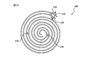
図1A〜2Cを参照すると、格納式支持装置100には、第1の双安定性部材110と、第2の双安定性部材120と、少なくとも1つの構造配置部材130と、が含まれ得る。第1の双安定性部材110及び第2の双安定性部材120は、収納に適しているコンパクトな形状と、第1の双安定性部材110及び第2の双安定性部材120が適切に配置する場合に荷重支持に適している拡張形態とを交互に取りうるように構成されている。少なくとも1つの構造配置部材130は、第1の双安定性部材110及び第2の双安定性部材120の接触を維持するように、又は互いに近接するように、そして、第1の双安定性部材及び第2の双安定性部材を互いに適切な配置に案内し拡張時の荷重を支持するように構成されている。
With reference to FIGS. 1A-2C, the
第1の双安定性部材110及び第2の双安定性部材120(「双安定性部材110、120」と総称する)はそれぞれ、縦軸線及び横軸線を有する双安定性片を備えている。双安定性部材110、120は少なくともそれぞれ、コイル状形態及び拡張形態のいずれかにおける半硬質構造安定性、並びに、他の形態における相対的構造不安定性を特徴とする。したがって、双安定性部材110、120はそれぞれ、適切な加圧によって、コイル状形態から拡張形態に、及び拡張形態からコイル状形態に比較的容易に変形することができる。
The first
双安定性部材110、120のコイル状形態は、直線状の横軸線及び湾曲した縦軸線を特徴とする。逆に、双安定性部材110、120の拡張形態は、直線状の縦軸線及び湾曲した横軸線を特徴とする。多くの変形例では、第1の双安定性部材110のコイル状形態及び第2の双安定性部材120のコイル状形態は、実質的に同一である。ただし、第1の双安定性部材110の拡張形態、及び第2の双安定性部材120の拡張形態は、通常、以下により詳細に説明するように、異なっており、対向する湾曲部を有する。
The coiled form of the
ここで図1Aを参照すると、装置100の一例は、コイル状形態で示されており、すなわち、第1の双安定性部材110と第2の双安定性部材120はともにコイル状形態にある。第1の双安定性部材110と第2の双安定性部材120は、コイル状形態にある場合、一緒に巻かれるか又は互いの周囲で巻かれることに留意する必要がある。明確にするためにのみ、第1の双安定性部材110及び第2の双安定性部材120は、比較的緩いコイル状で示されており、実質的に間隔をおいて配置されている。通常、実際には、第1の双安定性部材110と第2の双安定性部材120は、より緊密に一緒に巻かれる。
Referring now to FIG. 1A, an example of the
図1Aの構造配置部材130は、複数の可撓性締結部材、この例では複数のヒンジ式締結部材を備え、これらのそれぞれは、第1の双安定性部材及び第2の双安定性部材の隣接する側縁部に取り付けられている。図1B及び1Cは、コイル状形態から拡張形態へと部分的且つ完全に変形した図1Aの装置をそれぞれ示している。複数の可撓性締結部材のそれぞれのヒンジ部は、可撓性を付与し、これによって、ヒンジ式デュアルエンド締結部材(hinged, dual ended fastener)は、コイル状形態又は拡張形態のいずれかの場合に、第1の双安定性部材と第2の双安定性部材との接触を維持できることを理解できる。さらに、複数の可撓性締結部材は、伸長時に、第1の双安定性部材110及び第2の双安定性部材120を所望の構造配置に誘導し、図1Cに示されているように、横方向に囲まれた管を形成する。
The structural arrangement member 130 of FIG. 1A comprises a plurality of flexible fastening members, in this example a plurality of hinged fastening members, each of which is a first bistable member and a second bistable member. Attached to adjacent side edges. 1B and 1C show the device of FIG. 1A, respectively, partially and completely deformed from a coiled configuration to an expanded configuration. Each hinge portion of the plurality of flexible fastening members provides flexibility so that the hinged, dual ended fasteners can be in either a coiled form or an expanded form In addition, it can be understood that the contact between the first bistable member and the second bistable member can be maintained. Further, the plurality of flexible fastening members, when extended, guide the first
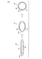
図2Aは、図1A〜Cによる装置の一連の断面図を示し、コイル状形態(左)、中間形態(中央)及び拡張形態(右)にある場合の、第1の双安定性部材110及び第2の双安定性部材120の横方向湾曲部又は横方向湾曲部がない場合を示す。図2Aの3つの断面図はそれぞれ、図1A〜Cの線A‐A、B‐B及びC‐Cに沿ったものである。図2Aの断面図は、装置100がコイル状形態から拡張形態に変化する場合に、構造配置部材130が、どのように、第1の双安定性部材110及び第2の双安定性部材120を、荷重を支持するのに適切な配置に誘導するかを更に示している。
FIG. 2A shows a series of cross-sectional views of the device according to FIGS. 1A-C, with the first
図1A〜1Cの装置100は複数のヒンジ式締結部材を有しているが、他の任意の適切な可撓性締結部材を用いることもできる。例えば、可撓性締結部材型の適切な構造配置部材130としては、可撓性材料から形成され、第1の双安定性部材110及び第2の双安定性部材120の隣接する側縁部に取り付けられる複数のフラップを挙げることができる。かかる可撓性材料には、可撓性布、可撓性膜、又は他の任意の可撓性材料が含まれ得る。他の場合において、構造配置部材130は、1つの可撓性締結部材であって、隣接した側縁部の長さの全体又は実質的部分に沿って第1の双安定性部材110及び第2の双安定性部材120の隣接した側縁部に固定された可撓性締結部材を具備することができる。更に別の例において、構造配置部材130は、第1の双安定性部材及び第2の双安定性部材のいずれか又は両方と一体に形成された1又は複数の可撓性締結部材を含み得る。
Although the
概して、第1の双安定性部材110及び第2の双安定性部材120は、拡張形態にある場合、コイル状形態にある場合の縦方向湾曲部に対して、対向する横方向湾曲関係を有する。図1Bの例を再び参照すると、第1の双安定性部材110の拡張部は、コイル状部の方向に面する凹面と、コイル状部の方向から外方に面する凸面と、を有している。これは「正の湾曲部関係(又は正の曲率関係)」と称することができ、この特性を有する材料は当該技術分野において公知である。これに対して、第2の双安定性部材120の拡張部は、コイル状部の方向に面する凸面と、コイル状部の方向から外方に面する凹面と、を有している。これは、「負の湾曲部関係(又は負の曲率関係)」と称することができる。図1Aの第1の双安定性部材110と第2の双安定性部材120との間の特定の対向する横方向湾曲関係によって、図1Bの例において互いに面する凹面を有した円筒状構造が生じるが、第1の双安定性部材110及び第2の双安定性部材120のそれぞれの横方向湾曲部は、格納式支持装置100が展開されると凸面が互いに面するように、逆にできることを理解する必要がある。
In general, the first
正の湾曲部関係を有する双安定性部材110又は120の製造方法は、通常、縦方向の拡張によって横方向の収縮が生じ、及び横方向の収縮によって縦方向の拡張が生じるように、正のポアソン比を有する二層又は多層の複合材料の製造を含む。この正のポアソン比によって、図1B、1Cの第1の双安定性部材の正の湾曲部関係が生じる。負の横方向湾曲部関係を有する第2の双安定性部材は、二層又は多層の複合材料で同様に設計されることができ、少なくともその一方は、負のポアソン比を有するオーセチック材料であり、縦方向の拡張は、横方向に拡張させ、逆に横方向の拡張は、縦方向に拡張させる。この負のポアソン比によって、図1B、1Cの例における第2の双安定性部材120の負の横方向湾曲部関係が生じる。かかるオーセチック材料の非限定的な例としては、構造繊維が周期的な逆多角形細胞構造を形成する複合材料が挙げられる。
A method of manufacturing a
ここで図2B及び2Cを参照すると、構造配置部材130は、代替的に、膜を備えた炭素繊維又はエポキシなどの可撓性封止部(flexible encapsulator)130bとされ得る。図2B及び2Cの断面図は、図1A〜1Cに類似する装置100のものであり、可撓性締結部材型の構造配置部材130は、可撓性封止部130bに代わり、図2B及び2Cのそれぞれにある3つの図は、図1A〜1Cの線A‐A、B‐B及びC‐Cと同様の線に沿っている。可撓性封止部130bは、第1の双安定性部材110及び第2の双安定性部材120のうちの少なくとも一部を覆い又は封止する種々の構造配置部材である。可撓性封止部130bは、靴下状又はスリーブ状の形状を有する膜、布又は他の可撓性材料であり得る。一部の変形例では、第1の双安定性部材110及び第2の双安定性部材120がコイル状形態にある場合、可撓性封止部130b型の構造配置部材は、第1の双安定性部材110及び第2の双安定性部材120とともに巻かれる。
Referring now to FIGS. 2B and 2C, the
図2Bを再び参照すると、左のパネルは、コイル状形態にある第1の双安定性部材110及び第2の双安定性部材120を示し、右のパネルは、拡張形態にある第1の双安定性部材110及び第2の双安定性部材120を示し、中央のパネルは、中間状態にある第1の双安定性部材110及び第2の双安定性部材120を示している。装置100が格納形態から展開形態に変化すると、可撓性封止部130b型の構造配置部材130は、この例では、第1の双安定性部材110及び第2の双安定性部材120を、最大耐荷重に必要な配置である管状にする。この管状配置では、第1の双安定性部材110及び第2の双安定性部材120の断面図は、円を形成するように終点でともに保持された2つの180°の円弧として示されている。
Referring again to FIG. 2B, the left panel shows the first
同様のシナリオが図2Cに表されているが、拡張形態にある場合、第1の双安定性部材110と第2の双安定性部材120の横方向湾曲部関係は、逆になる。この例では、可撓性封止部130b型の構造配置部材130は、正方形の縦方向縁部を有する形状を採用することが可能である。場合によっては、この例では構造配置部材130は均一に可撓性ではないが、代わりに、縦方向枢動軸線を有した硬質壁を有する。この例では、構造配置部材は、6つの硬質壁132A、1320B、132C、132D、132E及び132Fと、6つの縦方向枢動軸線133A、133B、133C、133D、133E及び133F(図2Cの端部断面図に枢動点として表される縦方向枢動軸線133A〜133F)を有し、これらは、構造配置部材が、装置100が格納される場合に六角形である縦方向縁部と、装置100が展開される場合に正方形である縦方向縁部とを交互に取るようにする。第1の双安定性部材110と第2の双安定性部材120の湾曲部関係の対向する極性とともに、正方形の可撓性封止部130bの特性により、第1の双安定性部材及び第2の双安定性部材は、これらの中間点で対称的に結合した2つの対向する円弧の縦方向縁部断面形状を有する構造にされる。装置100は、展開時に、全体として、直方体の形状である。図2Cの例には、締結部材140により取付け可能な任意の縦方向フラップ(図2Cの端部断面図には横方向フラップが表されている。)も含まれている。図2Cの右パネルのように、縦方向フラップが締結部材140に取り付けられている場合、これは、展開形態において装置100を維持するのに有用であり得る。
A similar scenario is depicted in FIG. 2C, but when in the expanded configuration, the lateral curvature relationship of the first
図3を参照すると、格納式支持装置の製造方法200も開示されている。方法200には、第1の双安定性部材110を設ける工程201が含まれている。また、方法には、第2の双安定性部材120を設ける工程202も含まれている。前述の双安定性部材を設ける工程201及び202において設けられる第1の双安定性部材110及び第2の双安定性部材120は、上述したとおりである。具体的には、それぞれ、縦方向直線部及び横方向湾曲部を有する安定した拡張形態と、縦方向湾曲部及び横方向直線部を有する安定したコイル状形態とを交互に取りうる。さらに、工程201において設けられる第1の双安定性部材110、及び工程202において設けられる第2の双安定性部材120は、概して、上述したように、互いに、対向する横方向湾曲部関係を有する。
Referring to FIG. 3, a
方法200には、第1の双安定性部材及び第2の双安定性部材と少なくとも1つの構造配置部材130とを接合する工程203も含まれている。接合工程203に用いられる構造配置部材130は、格納式支持装置100に関して上述したとおりである。したがって、第1の双安定性部材110及び第2の双安定性部材120が拡張形態にある場合、方法200に用いられる構造配置部材130は、格納式支持装置100を耐荷重形態に誘導するように構成される。同様に、方法200に用いるのに適している構造配置部材130の限定的でない例としては、上述したように、種々の形態の可撓性締結部材及び/又は可撓性封止部130bが挙げられる。
The
さらに、方法200には、第1の双安定性部材110及び第2の双安定性部材120を一緒に巻く工程が含まれ得る。この一緒に巻く工程は、接合工程に先行して又は接合工程の後に行うことができる。例えば、構造配置部材130がスリーブ形状の布のような可撓性封止部130bである場合、第1の双安定性部材110及び第2の双安定性部材120が拡張形態にあり、次いでこれから巻かれようとするとき、可撓性封止部130bスリーブは、第1の双安定性部材110及び第2の双安定性部材120に亘り摺動され得る。かかるアプローチによって、上述したように、可撓性封止部130bと第1の双安定性部材110及び第2の双安定性部材120とをともに巻くことができる。
Further, the
接合工程203に先行して一緒に巻く工程を行うことができる例では、第1の双安定性部材と第2の双安定性部材は、一緒に巻くことができ、可撓性締結部材型の1つ以上の可撓性構造配置部材130は、その後、第1の双安定性部材110及び第2の双安定性部材120の隣接する側縁部に取り付けることができる。
In an example in which the step of winding together prior to the joining
前述の説明は、現在最も実用的な実施形態であると考えられるものに関する。ただし、本開示はこれらの実施形態に限定されるものではなく、その一方で、添付の特許請求の範囲の趣旨及び範囲内に含まれる種々の変更及び同等の構成を包含するものとすることを理解する必要があり、法律の下で許可されているとおりに、すべてのかかる変更及び同等の構造を包含するように、その範囲は最も広く解釈される必要がある。 The foregoing description relates to what is presently considered to be the most practical embodiment. However, the present disclosure is not limited to these embodiments, and on the other hand, includes various modifications and equivalent configurations included in the spirit and scope of the appended claims. The scope should be construed most broadly to encompass all such modifications and equivalent structures, as should be understood and permitted under law.
100 格納式支持装置
110 第1の双安定性部材
120 第2の双安定性部材
130 構造配置部材
DESCRIPTION OF
Claims (13)
縦方向直線部及び横方向湾曲部を有する安定した拡張形態と縦方向湾曲部及び横方向直線部を有する安定したコイル状形態との間で切り換え可能な第1の双安定性部材であって、該第1の双安定性部材の拡張部は、前記第1の双安定性部材が部分的に拡張形態で及び部分的にコイル状形態の場合に、前記第1の双安定性部材のコイル状部の方向に面する凹面と、前記コイル状部の方向から外方に面する凸面と、を有する前記第1の双安定性部材と、
縦方向直線部及び横方向湾曲部を有する安定した拡張形態と縦方向湾曲部及び横方向直線部を有する安定したコイル状形態との間で切り換え可能な第2の双安定性部材であって、該第2の双安定性部材は第1層及び第2層を有し、該第1層及び第2層の少なくとも一方はオーセチック材料を具備し、前記第1層及び第2層は、前記第2の双安定性部材が部分的に拡張形態で及び部分的にコイル状形態の場合に、前記第2の双安定性部材の拡張部が前記第2の双安定性部材のコイル状部の方向に面する凸面と、該コイル状部の方向から外方に面する凹面とを有するように構成されている、前記第2の双安定性部材と、
前記拡張形態及び前記コイル状形態の両方において、前記第1の双安定性部材及び前記第2の双安定性部材の隣接する側縁部に対して取り付けられ、前記第1の双安定性部材及び前記第2の双安定性部材とは別個の少なくとも1つの可撓性締結部材と、
を具備し、
前記第1の双安定性部材と前記第2の双安定性部材のうちの前記第2の双安定性部材のみが、前記オーセチック材料を具備する、格納式支持装置。 A retractable support device,
A first bistable member switchable between a stable expanded configuration having a longitudinal linear portion and a laterally curved portion and a stable coiled configuration having a longitudinally curved portion and a laterally linear portion, The expanded portion of the first bistable member is coiled of the first bistable member when the first bistable member is partially expanded and partially coiled. The first bistable member having a concave surface facing the direction of the part and a convex surface facing outward from the direction of the coiled part;
A second bistable member switchable between a stable expanded configuration having a longitudinal linear portion and a laterally curved portion and a stable coiled configuration having a longitudinally curved portion and a laterally linear portion, The second bistable member includes a first layer and a second layer, and at least one of the first layer and the second layer includes an auxetic material, and the first layer and the second layer include the first layer and the second layer, respectively. When the two bistable members are partially expanded and partially coiled, the expanded portion of the second bistable member is oriented in the coiled portion of the second bistable member. A second bistable member configured to have a convex surface facing the surface and a concave surface facing outward from the direction of the coiled portion;
Attached to adjacent side edges of the first bistable member and the second bistable member in both the expanded configuration and the coiled configuration, the first bistable member and At least one flexible fastening member separate from the second bistable member;
Equipped with,
A retractable support device , wherein only the second bistable member of the first bistable member and the second bistable member comprises the auxetic material .
縦方向直線部及び横方向湾曲部を有する安定した拡張形態と、縦方向湾曲部及び横方向直線部を有する安定したコイル状形態との間で切り換え可能な第1の双安定性部材を設けることと、
縦方向直線部及び横方向湾曲部を有する安定した拡張形態と縦方向湾曲部及び横方向直線部を有する安定したコイル状形態との間で切り換え可能な第2の双安定性部材を設けることと、
前記拡張形態又は前記コイル状形態のいずれかにあるときに、前記第1の双安定性部材及び前記第2の双安定性部材を、前記第1の双安定性部材及び前記第2の双安定性部材を結合するように構成された少なくとも1つの構造配置部材と結合することと、を含み、
前記第1の双安定性部材及び前記第2の双安定性部材は、互いに対して対向する横方向湾曲部関係を有し、前記第1の双安定性部材の拡張部は、前記第1の双安定性部材が部分的に拡張形態で及び部分的にコイル状形態の場合に、前記第1の双安定性部材のコイル状部の方向に面する凹面と、前記コイル状部の方向から外方に面する凸面と、を有し、前記第2の双安定性部材が部分的に拡張形態で及び部分的にコイル状形態の場合に、前記第2の双安定性部材の拡張部が前記第2の双安定性部材のコイル状部の方向に面する凸面と、前記コイル状部の方向から外方に面する凹面とを有し、前記装置は、前記第1の双安定性部材及び前記第2の双安定性部材が拡張形態にある場合に、前記第1の双安定性部材及び前記第2の双安定性部材の凸面が互いに接触するように構成され、前記第1の双安定性部材と前記第2の双安定性部材のうちのいずれか一方の双安定性部材のみが、前記オーセチック材料を具備する、方法。 A method of manufacturing a retractable support device, comprising:
Providing a first bistable member switchable between a stable expanded configuration having a longitudinal linear portion and a laterally curved portion and a stable coiled configuration having a longitudinally curved portion and a laterally linear portion When,
Providing a second bistable member switchable between a stable expanded configuration having a longitudinal linear portion and a laterally curved portion and a stable coiled configuration having a longitudinally curved portion and a laterally linear portion; ,
When in either the expanded configuration or the coiled configuration, the first bistable member and the second bistable member are replaced with the first bistable member and the second bistable member. Coupling with at least one structural arrangement member configured to couple the sex member;
The first bistable member and the second bistable member have a transverse curve relationship that opposes each other, and the extension of the first bistable member is the first bistable member. When the bistable member is partially expanded and partially coiled, a concave surface facing the coiled portion of the first bistable member and out of the direction of the coiled portion And when the second bistable member is partially expanded and partially coiled, the extended portion of the second bistable member is A convex surface facing the direction of the coiled portion of the second bistable member; and a concave surface facing outward from the direction of the coiled portion, wherein the device comprises the first bistable member and Convex surfaces of the first bistable member and the second bistable member when the second bistable member is in an expanded configuration. Is configured to contact each other, only one of the bistable member of said first bistable element and said second bistable member comprises the auxetic material.
縦方向直線部及び横方向湾曲部を有する安定した拡張形態と縦方向湾曲部及び横方向直線部を有する安定したコイル状形態との間で切り換え可能な第1の双安定性部材と、A first bistable member switchable between a stable expanded configuration having a longitudinal linear portion and a laterally curved portion and a stable coiled configuration having a longitudinally curved portion and a laterally linear portion;
縦方向直線部及び横方向湾曲部を有する安定した拡張形態と縦方向湾曲部及び横方向直線部を有する安定したコイル状形態との間で切り換え可能な第2の双安定性部材と、A second bistable member switchable between a stable expanded configuration having a longitudinal linear portion and a laterally curved portion and a stable coiled configuration having a longitudinally curved portion and a laterally linear portion;
前記拡張形態及び前記コイル状形態の両方において、前記第1の双安定性部材及び前記第2の双安定性部材の少なくとも一部を覆い又は封止する少なくとも1つの可撓性封止部と、を具備し、At least one flexible seal covering or sealing at least a portion of the first bistable member and the second bistable member in both the expanded configuration and the coiled configuration; Comprising
前記第1の双安定性部材及び前記第2の双安定性部材は、互いに対して対向する横方向湾曲部関係を有し、前記第1の双安定性部材の拡張部は、前記第1の双安定性部材が部分的に拡張形態で及び部分的にコイル状形態の場合に、前記第1の双安定性部材のコイル状部の方向に面する凹面と、前記コイル状部の方向から外方に面する凸面と、を有し、前記第2の双安定性部材が部分的に拡張形態で及び部分的にコイル状形態の場合に、前記第2の双安定性部材の拡張部が前記第2の双安定性部材のコイル状部の方向に面する凸面と、前記コイル状部の方向から外方に面する凹面とを有し、前記装置は、前記第1の双安定性部材及び前記第2の双安定性部材の各々が拡張形態にある場合に、前記第1の双安定性部材及び前記第2の双安定性部材の凸面が互いに接触するように構成されていて、The first bistable member and the second bistable member have a transverse curve relationship that opposes each other, and the extension of the first bistable member is the first bistable member. When the bistable member is partially expanded and partially coiled, a concave surface facing the coiled portion of the first bistable member and out of the direction of the coiled portion And when the second bistable member is partially expanded and partially coiled, the extended portion of the second bistable member is A convex surface facing the direction of the coiled portion of the second bistable member; and a concave surface facing outward from the direction of the coiled portion, wherein the device comprises the first bistable member and The first bistable member and the second bistable member when each of the second bistable members is in an expanded configuration. Convex surfaces have been configured to contact each other,
前記第1の双安定性部材及び前記第2の双安定性部材のいずれか一方のみが、オーセチック材料を具備する、格納式支持装置。The retractable support device, wherein only one of the first bistable member and the second bistable member comprises an auxetic material.
Applications Claiming Priority (2)
| Application Number | Priority Date | Filing Date | Title |
|---|---|---|---|
| US14/581,396 US9580907B2 (en) | 2014-12-23 | 2014-12-23 | Bi-stable material to develop stowable high strength column |
| US14/581,396 | 2014-12-23 |
Publications (3)
| Publication Number | Publication Date |
|---|---|
| JP2016130447A JP2016130447A (en) | 2016-07-21 |
| JP2016130447A5 JP2016130447A5 (en) | 2017-02-09 |
| JP6251231B2 true JP6251231B2 (en) | 2017-12-20 |
Family
ID=56128797
Family Applications (1)
| Application Number | Title | Priority Date | Filing Date |
|---|---|---|---|
| JP2015242268A Active JP6251231B2 (en) | 2014-12-23 | 2015-12-11 | Retractable support device and manufacturing method thereof |
Country Status (2)
| Country | Link |
|---|---|
| US (1) | US9580907B2 (en) |
| JP (1) | JP6251231B2 (en) |
Families Citing this family (18)
| Publication number | Priority date | Publication date | Assignee | Title |
|---|---|---|---|---|
| US9611056B1 (en) * | 2011-01-20 | 2017-04-04 | Deployable Space Systems, Inc. | Directionally controlled elastically deployable roll-out solar array |
| US9863148B2 (en) * | 2015-08-28 | 2018-01-09 | The United States Of America As Represented By The Administrator Of Nasa | Sheath-based rollable lenticular-shaped and low-stiction composite boom |
| JP6590218B2 (en) * | 2016-07-01 | 2019-10-16 | サカセ・アドテック株式会社 | Bistable boom |
| US10611502B2 (en) | 2016-10-20 | 2020-04-07 | Roccor, Llc | Precision deployment devices, systems, and methods |
| ES2773720T3 (en) * | 2016-12-20 | 2020-07-14 | Airbus Operations Sl | Energy absorption structure to attenuate the energy transmitted by an energy source |
| GB201703040D0 (en) * | 2017-02-24 | 2017-04-12 | Rtl Mat Ltd | Slit tube extendible members and methods for manufacturing same |
| GB201713482D0 (en) * | 2017-08-22 | 2017-10-04 | Rtl Mat Ltd | Slit locking clamp for mast and support assembly |
| EP3530561B1 (en) | 2018-02-27 | 2024-06-19 | Airbus Operations, S.L. | Auxetic bi-stable structure |
| US11047132B2 (en) * | 2018-05-27 | 2021-06-29 | Roccor, Llc | Boom deployer devices, systems, and methods |
| DE102018112690B4 (en) * | 2018-05-28 | 2022-02-17 | Deutsches Zentrum für Luft- und Raumfahrt e.V. | Device for unfolding a rolled-up elongate hollow body |
| US11199005B2 (en) * | 2018-07-06 | 2021-12-14 | United States Of America As Represented By The Administrator Of Nasa | Bistable collapsible tubular mast boom |
| FR3100862A1 (en) * | 2019-09-18 | 2021-03-19 | Explorcam | Transportable zone lighting kit |
| CN110550237B (en) * | 2019-10-12 | 2022-09-23 | 上海宇航系统工程研究所 | Unfolding control device of thin-wall extending arm |
| EP4158120A4 (en) * | 2020-06-02 | 2024-06-26 | Opterus Research and Development, Inc. | Living hinge boom |
| US11435067B1 (en) * | 2021-03-03 | 2022-09-06 | Rtl Materials Ltd. | Coilable lighting apparatus with bistable mast |
| DE102021004261B3 (en) | 2021-08-20 | 2023-02-02 | Oliver Kessler Design Gmbh | LED lighting elements that can be dismantled into their various components and rolled up |
| CN113928882B (en) * | 2021-10-19 | 2022-12-20 | 北京航空航天大学 | Thick pod rod stretching device |
| US11771183B2 (en) | 2021-12-16 | 2023-10-03 | Joon Bu Park | Negative Poisson's ratio materials for fasteners |
Family Cites Families (24)
| Publication number | Priority date | Publication date | Assignee | Title |
|---|---|---|---|---|
| US1947392A (en) * | 1931-03-02 | 1934-02-13 | Guntermann Wilhelm | Hollow rod |
| US2352526A (en) * | 1939-03-16 | 1944-06-27 | Hiram A Farrand | Collapsible structure |
| US2840199A (en) * | 1953-03-23 | 1958-06-24 | Ultra Electric Inc | Collapsible aerials |
| US3434254A (en) * | 1965-10-04 | 1969-03-25 | Trw Inc | Deployable boom |
| US3360894A (en) * | 1966-06-20 | 1968-01-02 | Melpar Inc | Extendible interlocked boom |
| US3508587A (en) * | 1966-09-29 | 1970-04-28 | Hans A Mauch | Tubular structural member |
| US3503164A (en) * | 1968-01-03 | 1970-03-31 | Fairchild Hiller Corp | Tubular extendable structure |
| US3749133A (en) * | 1971-04-02 | 1973-07-31 | Frw Inc | Strain energy erectile tubular beam with stitched flanges |
| US3691705A (en) * | 1971-05-24 | 1972-09-19 | Trw Inc | Self-erecting collapsible and foldable tubular beam |
| US5235788A (en) * | 1990-08-08 | 1993-08-17 | Lembit Maimets | Enclosure assembly and method of constructing same |
| GB9812048D0 (en) | 1998-06-04 | 1998-07-29 | Daton Lovett Andrew J | Means for combining extendible,coilable members to create compound struts |
| WO2000026482A2 (en) * | 1998-11-03 | 2000-05-11 | A.P.S. Advanced Pneumatic Structures Ltd. | A collapsible structural element |
| US6431271B1 (en) | 2000-09-20 | 2002-08-13 | Schlumberger Technology Corporation | Apparatus comprising bistable structures and methods for their use in oil and gas wells |
| US6910304B2 (en) * | 2002-04-02 | 2005-06-28 | Foster-Miller, Inc. | Stiffener reinforced foldable member |
| EP1737564B1 (en) * | 2004-03-12 | 2019-09-11 | SRI International | Mechanical meta-materials |
| US7694465B2 (en) * | 2005-04-08 | 2010-04-13 | Alliant Techsystems Inc. | Deployable structural assemblies, systems for deploying such structural assemblies and related methods |
| GB2445572B8 (en) * | 2007-01-15 | 2012-03-28 | Eugene H C Leung | Intelligent bi-stable structure system. |
| EP2352435B1 (en) | 2008-10-31 | 2019-11-27 | Sinclair Pharmaceuticals Limited | Minimally invasive tissue support system with a superior tissue support and an inferior anchor |
| JP5276952B2 (en) | 2008-11-05 | 2013-08-28 | サカセ・アドテック株式会社 | Extension structure |
| US8302696B2 (en) * | 2010-04-06 | 2012-11-06 | Baker Hughes Incorporated | Actuator and tubular actuator |
| GB2491822B (en) * | 2011-06-09 | 2015-12-02 | Rtl Materials Ltd | Coilable extendible member and methods |
| DE102012100487A1 (en) * | 2012-01-20 | 2013-07-25 | Nopper Design UG (haftungsbeschränkt) | Foldable construction element for mechanically loadable, collapsible constructive arrangements |
| JP6044029B2 (en) * | 2012-07-02 | 2016-12-14 | サカセ・アドテック株式会社 | Extension structure |
| JP5882151B2 (en) * | 2012-07-11 | 2016-03-09 | サカセ・アドテック株式会社 | Extension structure |
-
2014
- 2014-12-23 US US14/581,396 patent/US9580907B2/en active Active
-
2015
- 2015-12-11 JP JP2015242268A patent/JP6251231B2/en active Active
Also Published As
| Publication number | Publication date |
|---|---|
| JP2016130447A (en) | 2016-07-21 |
| US20160177567A1 (en) | 2016-06-23 |
| US9580907B2 (en) | 2017-02-28 |
Similar Documents
| Publication | Publication Date | Title |
|---|---|---|
| JP6251231B2 (en) | Retractable support device and manufacturing method thereof | |
| US10100951B2 (en) | Coilable extendible member and methods | |
| US7895795B1 (en) | Triangular rollable and collapsible boom | |
| JP2016130447A5 (en) | ||
| CN106564621B (en) | It is a kind of to realize the X-type section boom for collapsing expansion function | |
| US10071823B2 (en) | Extendible boom | |
| US3434254A (en) | Deployable boom | |
| US20070145195A1 (en) | Deployable array support structure | |
| WO2016174520A1 (en) | Expandable and contractible hose | |
| US10119266B1 (en) | Extensible sparse-isogrid column | |
| JP2010500522A5 (en) | ||
| US20230373659A1 (en) | Edge registration for shearless extendible booms | |
| JP5882151B2 (en) | Extension structure | |
| CN103712052A (en) | Flexible thin-walled supporting structure | |
| US20210372464A1 (en) | Living hinge boom | |
| US20200011057A1 (en) | Bistable Collapsible Tubular Mast Boom | |
| CN203628061U (en) | Steel belt reinforced corrugated pipe | |
| JP6744091B2 (en) | Tape with smooth development | |
| JPH03125697A (en) | Tubular structural material capable of folding and storing | |
| CN109866943A (en) | A kind of thin walled bar support device of inflation driving expansion | |
| CN107240757A (en) | It is a kind of new from resilience reconfigurable satellite-borne deployable antenna | |
| US20230407999A1 (en) | Hybrid inflatable boom | |
| Brown et al. | A deployable truss beam for long or lightly loaded space applications | |
| Jasion et al. | Stabilisation of a post-critical behaviour of sandwich cylindrical shells | |
| CN105508861B (en) | A kind of foldable hollow board holding |
Legal Events
| Date | Code | Title | Description |
|---|---|---|---|
| A521 | Request for written amendment filed |
Free format text: JAPANESE INTERMEDIATE CODE: A523 Effective date: 20161227 |
|
| A621 | Written request for application examination |
Free format text: JAPANESE INTERMEDIATE CODE: A621 Effective date: 20161227 |
|
| A871 | Explanation of circumstances concerning accelerated examination |
Free format text: JAPANESE INTERMEDIATE CODE: A871 Effective date: 20161227 |
|
| A975 | Report on accelerated examination |
Free format text: JAPANESE INTERMEDIATE CODE: A971005 Effective date: 20170222 |
|
| A131 | Notification of reasons for refusal |
Free format text: JAPANESE INTERMEDIATE CODE: A131 Effective date: 20170228 |
|
| A521 | Request for written amendment filed |
Free format text: JAPANESE INTERMEDIATE CODE: A523 Effective date: 20170530 |
|
| A131 | Notification of reasons for refusal |
Free format text: JAPANESE INTERMEDIATE CODE: A131 Effective date: 20170613 |
|
| TRDD | Decision of grant or rejection written | ||
| A01 | Written decision to grant a patent or to grant a registration (utility model) |
Free format text: JAPANESE INTERMEDIATE CODE: A01 Effective date: 20171024 |
|
| A61 | First payment of annual fees (during grant procedure) |
Free format text: JAPANESE INTERMEDIATE CODE: A61 Effective date: 20171124 |
|
| R150 | Certificate of patent or registration of utility model |
Ref document number: 6251231 Country of ref document: JP Free format text: JAPANESE INTERMEDIATE CODE: R150 |
|
| S111 | Request for change of ownership or part of ownership |
Free format text: JAPANESE INTERMEDIATE CODE: R313113 |
|
| R350 | Written notification of registration of transfer |
Free format text: JAPANESE INTERMEDIATE CODE: R350 |