JP6249535B2 - Housing with removable locking element - Google Patents
Housing with removable locking element Download PDFInfo
- Publication number
- JP6249535B2 JP6249535B2 JP2015535126A JP2015535126A JP6249535B2 JP 6249535 B2 JP6249535 B2 JP 6249535B2 JP 2015535126 A JP2015535126 A JP 2015535126A JP 2015535126 A JP2015535126 A JP 2015535126A JP 6249535 B2 JP6249535 B2 JP 6249535B2
- Authority
- JP
- Japan
- Prior art keywords
- housing
- locking
- locking element
- receiving portion
- engagement
- Prior art date
- Legal status (The legal status is an assumption and is not a legal conclusion. Google has not performed a legal analysis and makes no representation as to the accuracy of the status listed.)
- Active
Links
- 230000008859 change Effects 0.000 claims description 2
- 230000007246 mechanism Effects 0.000 description 59
- 238000000034 method Methods 0.000 description 6
- 238000012806 monitoring device Methods 0.000 description 6
- 230000004308 accommodation Effects 0.000 description 3
- 239000012530 fluid Substances 0.000 description 3
- 230000008569 process Effects 0.000 description 3
- 239000013598 vector Substances 0.000 description 3
- 230000001419 dependent effect Effects 0.000 description 2
- 239000007788 liquid Substances 0.000 description 2
- 238000012423 maintenance Methods 0.000 description 2
- 238000004519 manufacturing process Methods 0.000 description 2
- 239000000853 adhesive Substances 0.000 description 1
- 230000001070 adhesive effect Effects 0.000 description 1
- QVGXLLKOCUKJST-UHFFFAOYSA-N atomic oxygen Chemical compound [O] QVGXLLKOCUKJST-UHFFFAOYSA-N 0.000 description 1
- 230000009286 beneficial effect Effects 0.000 description 1
- 230000008901 benefit Effects 0.000 description 1
- 239000008280 blood Substances 0.000 description 1
- 210000004369 blood Anatomy 0.000 description 1
- 230000036772 blood pressure Effects 0.000 description 1
- 238000004140 cleaning Methods 0.000 description 1
- 239000012459 cleaning agent Substances 0.000 description 1
- 238000009826 distribution Methods 0.000 description 1
- 239000007789 gas Substances 0.000 description 1
- 230000014759 maintenance of location Effects 0.000 description 1
- 230000013011 mating Effects 0.000 description 1
- 239000001301 oxygen Substances 0.000 description 1
- 229910052760 oxygen Inorganic materials 0.000 description 1
- 230000000737 periodic effect Effects 0.000 description 1
- 230000009467 reduction Effects 0.000 description 1
- 230000008439 repair process Effects 0.000 description 1
- 238000000926 separation method Methods 0.000 description 1
- 230000003068 static effect Effects 0.000 description 1
- XLYOFNOQVPJJNP-UHFFFAOYSA-N water Substances O XLYOFNOQVPJJNP-UHFFFAOYSA-N 0.000 description 1
- 230000037303 wrinkles Effects 0.000 description 1
Images


Classifications
-
- G—PHYSICS
- G06—COMPUTING; CALCULATING OR COUNTING
- G06F—ELECTRIC DIGITAL DATA PROCESSING
- G06F1/00—Details not covered by groups G06F3/00 - G06F13/00 and G06F21/00
- G06F1/16—Constructional details or arrangements
- G06F1/1601—Constructional details related to the housing of computer displays, e.g. of CRT monitors, of flat displays
-
- G—PHYSICS
- G06—COMPUTING; CALCULATING OR COUNTING
- G06F—ELECTRIC DIGITAL DATA PROCESSING
- G06F1/00—Details not covered by groups G06F3/00 - G06F13/00 and G06F21/00
- G06F1/16—Constructional details or arrangements
- G06F1/1613—Constructional details or arrangements for portable computers
- G06F1/1626—Constructional details or arrangements for portable computers with a single-body enclosure integrating a flat display, e.g. Personal Digital Assistants [PDAs]
-
- H—ELECTRICITY
- H05—ELECTRIC TECHNIQUES NOT OTHERWISE PROVIDED FOR
- H05K—PRINTED CIRCUITS; CASINGS OR CONSTRUCTIONAL DETAILS OF ELECTRIC APPARATUS; MANUFACTURE OF ASSEMBLAGES OF ELECTRICAL COMPONENTS
- H05K5/00—Casings, cabinets or drawers for electric apparatus
- H05K5/0004—Casings, cabinets or drawers for electric apparatus comprising several parts forming a closed casing
- H05K5/0013—Casings, cabinets or drawers for electric apparatus comprising several parts forming a closed casing assembled by resilient members
-
- H—ELECTRICITY
- H05—ELECTRIC TECHNIQUES NOT OTHERWISE PROVIDED FOR
- H05K—PRINTED CIRCUITS; CASINGS OR CONSTRUCTIONAL DETAILS OF ELECTRIC APPARATUS; MANUFACTURE OF ASSEMBLAGES OF ELECTRICAL COMPONENTS
- H05K5/00—Casings, cabinets or drawers for electric apparatus
- H05K5/0017—Casings, cabinets or drawers for electric apparatus with operator interface units
-
- H—ELECTRICITY
- H05—ELECTRIC TECHNIQUES NOT OTHERWISE PROVIDED FOR
- H05K—PRINTED CIRCUITS; CASINGS OR CONSTRUCTIONAL DETAILS OF ELECTRIC APPARATUS; MANUFACTURE OF ASSEMBLAGES OF ELECTRICAL COMPONENTS
- H05K5/00—Casings, cabinets or drawers for electric apparatus
- H05K5/02—Details
- H05K5/0217—Mechanical details of casings
- H05K5/0221—Locks; Latches
Description
本発明は、ハウジング、特に患者モニタに関するハウジングに関する。これは、少なくとも2つの収容部分と、少なくとも1つの第1の収容部分に移動可能に構成される少なくとも1つの係止要素と、この少なくとも1つの係止要素を動かすことにより、少なくとも1つの第2の収容部分において第2の係合部分と相互作用する複数の第1の係合部分とを有する。更に、本発明は、斯かるハウジングを持つモニタデバイスに関する。 The present invention relates to a housing, and more particularly to a housing for a patient monitor. This comprises at least two receiving parts, at least one locking element configured to be movable to at least one first receiving part, and moving at least one second locking element by moving at least one second locking element. And a plurality of first engaging portions that interact with the second engaging portion. The invention further relates to a monitoring device having such a housing.
ハウジングに関して使用される一般的な係止要素は、整合する係合部分の1つ又は複数のペアを有する。そこでは、2つの係合部分のそれぞれの1つが、ハウジングの1つの部分に構成される。収容部分がまとめられるとき、それらが互いに係合した状態にされることができるよう、これらの整合する係合部分はこれらの収容部分に構成される。これは、例えば、2つの係合部分がネジ及び穴により実現される場合、あらゆるロック機構に対して個別的に作動されなければならない別々の機構により実現されることができ、又は1つの係合部分が他の係合部分にラッチすることで係合した状態が実現されるよう、少なくとも1つの係合部分がバイアスされることにより実現されることができる。 A typical locking element used with a housing has one or more pairs of mating engagement portions. There, one of each of the two engaging parts is configured in one part of the housing. These matching engaging portions are configured in these receiving portions so that when the receiving portions are brought together they can be brought into engagement with each other. This can be achieved, for example, by separate mechanisms that must be actuated individually for every locking mechanism, if the two engaging parts are realized by screws and holes, or one engagement It can be achieved by biasing at least one engagement portion so that the engaged state is achieved by latching the portion to the other engagement portion.
ロック機構としてネジを使用することはしばしば、異なる収容部分の不均等な固定をもたらし、液体又は他の不必要な流体がハウジングの内部に入ることを許す追加的なエントリポイントを、例えばネジが外側からアクセス可能な領域において提供する。上述したラッチング機構を持つハウジングは他方で、分解するのが困難である。その結果、ハウジングにおけるデバイスの保守に時間がかかり、結果として外部ハウジング表面の不必要で許容できない損傷を生じさせる。 The use of screws as a locking mechanism often results in an unequal fixation of different containment parts and provides additional entry points that allow liquids or other unwanted fluids to enter the interior of the housing, e.g. the screws on the outside Provided in an area accessible from. On the other hand, the housing with the latching mechanism described above is difficult to disassemble. As a result, device maintenance in the housing is time consuming and results in unnecessary and unacceptable damage to the outer housing surface.
本発明の目的は、ハウジング、及び斯かるハウジングを持つモニタデバイスを提供することである。これは、全体のハウジングが液体又は他の流体に関して不必要な開口部を提供せず、更に非常に容易に分解されることができる態様において、互いに解放可能に構成されることができる少なくとも2つの収容部分を有する。 An object of the present invention is to provide a housing and a monitoring device having such a housing. This is because at least two of the entire housing can be configured to be releasable from each other in a manner that does not provide unnecessary openings for liquids or other fluids and can be very easily disassembled. It has a receiving part.
本発明の側面において、ハウジングが、
第1の内壁を持つ少なくとも1つの第1の収容部分と、
第2の内壁を持つ少なくとも1つの第2の収容部分と、
少なくとも1つの係止要素とを具備し、
上記少なくとも1つの係止要素が、少なくとも1つの経路に沿って少なくとも1つの第1の収容部分に移動可能に構成され、かつ複数の第1の係合部分を有し、
上記少なくとも1つの第2の収容部分は、上記第2の内壁に複数の第2の係合部分を有し、
上記第1の係合部分の各1つが、係合状態及び係合していない状態の間で少なくとも変化されることができる1つの対応する第2の係合部分との解放可能な適合された接続(releasable fit connection:リリーサブルフィット接続)を形成し、
これらの少なくとも2つの状態の間の上記変化は、上記少なくとも1つの経路に沿って上記個別の係止要素を移動することにより、係止要素における上記第1の係合部分及び上記対応する第2の係合部分に対して同時に実現される。
In an aspect of the invention, the housing is
At least one first receiving portion having a first inner wall;
At least one second receiving portion having a second inner wall;
Comprising at least one locking element;
The at least one locking element is configured to be movable along at least one path to at least one first receiving portion and has a plurality of first engaging portions;
The at least one second accommodating portion has a plurality of second engaging portions on the second inner wall,
Each one of the first engagement portions is releasably adapted with one corresponding second engagement portion that can be changed at least between an engaged state and an unengaged state. Form a connection (releasable fit connection)
The change between these at least two states is caused by moving the individual locking elements along the at least one path, whereby the first engagement portion and the corresponding second in the locking elements. This is realized simultaneously with respect to the engaging portions.
本発明の別の態様によれば、モニタデバイス、好ましくは患者モニタが、
情報を提示するディスプレイと、
本発明によるハウジングとを具備する。
According to another aspect of the present invention, a monitoring device, preferably a patient monitor,
A display for presenting information;
And a housing according to the present invention.
係止要素を移動することにより、対応する第1及び第2の係合部分の個別のペアが、ちょうど1度の作動により、係合状態(又は係合していない状態)にされることができる。これにより、均一に閉じられる状態が実現されることができる。更に、ハウジングの内部において第1及び第2の係合部分を提供することにより、即ち少なくとも1つの第1及び第2の収容部分の内壁に提供することにより、第1及び第2の係合部分のすべてのペアにアクセスするための開口部は、必要でない。必要であれば、係止要素は、ハウジングにおけるたった1つの開口部を介して作動されることができる。この例示的な実施形態の他に、磁気又は電子的に制御される作動といった、直接のアクセスを必要とすることなくハウジングを通り機能する他の作動方法も、もちろん可能である。係合部分の全てのペアに関して複数の開口部がないこと、及び少なくとも2つの収容部分の不均等な閉鎖がないことにより、滑らかで安全に閉じられるハウジングが提供される。全体のハウジングの設計にプラスの影響を与える他に、外側から見られるこれらの開口部及び係止要素がないことは、水、洗浄剤又はガスといった流体に対して気密であるハウジングを提供する。デバイスが、医学分野でしばしば起こる定期的な洗浄処理を受ける場合、及び患者モニタといったモニタデバイスのような医療デバイスである場合、これは特に有益である。また、複数の係合部分を同時に作動させ、これによりたった1度の作動で係合状態又は係合していない状態を提供することにより、ハウジングの高速なアセンブリ又は分解が可能である。従って、例えば保守及び/又は修理が行われる場合、ハウジングは、比較的簡単かつ高速に再度開かれる及び閉じられることができる。また、これは、斯かるハウジングを用いて、例えばモニタデバイスといったデバイスのより速い製造プロセスをもたらす。これは、個別のデバイスを製造する全体の経費を更に減らすことにつながる。 By moving the locking element, the corresponding individual pair of first and second engaging portions can be brought into engagement (or disengaged) with just one actuation. it can. Thereby, the state closed uniformly can be implement | achieved. Furthermore, by providing first and second engaging portions within the housing, i.e. by providing on the inner wall of at least one first and second receiving portion, the first and second engaging portions. No openings are needed to access all pairs. If necessary, the locking element can be actuated through only one opening in the housing. In addition to this exemplary embodiment, other actuation methods that function through the housing without requiring direct access are of course possible, such as magnetically or electronically controlled actuation. The absence of multiple openings for all pairs of engagement portions and the absence of unequal closure of at least two receiving portions provide a housing that is smoothly and safely closed. In addition to having a positive impact on the overall housing design, the absence of these openings and locking elements seen from the outside provides a housing that is airtight to fluids such as water, cleaning agents or gases. This is particularly beneficial when the device undergoes a periodic cleaning process that often occurs in the medical field and when it is a medical device such as a monitoring device such as a patient monitor. Also, high speed assembly or disassembly of the housing is possible by actuating multiple engaging portions simultaneously, thereby providing an engaged or disengaged state with only one actuation. Thus, for example, when maintenance and / or repairs are performed, the housing can be reopened and closed relatively easily and quickly. This also results in a faster manufacturing process for devices such as monitor devices using such a housing. This leads to a further reduction in the overall cost of manufacturing individual devices.
本発明の好ましい実施形態は、従属項において規定される。 Preferred embodiments of the invention are defined in the dependent claims.
ハウジングのある実施形態によれば、少なくとも1つの経路は、少なくとも1つの係止要素の並進運動をもたらす。斯かる設計により、作動及び従って、係合状態及び係合していない状態の確立が、係止要素を長手の経路に沿って移動させることにより実現される。この経路は、まっすぐでもよいし、又は湾曲形状を有することもできる。従って、係合状態及び係合していない状態の実現は例えば、プッシュ及びプル運動を介して実現されることができる。 According to an embodiment of the housing, the at least one path provides a translational movement of the at least one locking element. With such a design, actuation and thus establishment of the engaged and disengaged state is achieved by moving the locking element along the longitudinal path. This path may be straight or may have a curved shape. Thus, realization of the engaged state and the non-engaged state can be realized, for example, via push and pull movements.
ハウジングの別の実施形態によれば、少なくとも1つの経路は、少なくとも1つの係止要素の回転運動をもたらす。斯かる係止要素は好ましくは、回転軸周りで可動に個別の収容部分において構成される。斯かる構成は、非常にコンパクトな態様において実現されることができ、開く及び閉じる手順、即ち係合及び離脱のために多くの空間を必要としない。 According to another embodiment of the housing, the at least one path provides a rotational movement of the at least one locking element. Such a locking element is preferably configured in a separate receiving part so as to be movable about the axis of rotation. Such an arrangement can be realized in a very compact manner and does not require a lot of space for the opening and closing procedures, ie engagement and disengagement.
ハウジングの別の実施形態によれば、ハウジングは、複数の係止要素、好ましくは2〜4つの係止要素を有し、これはより好ましくは、4つ、3つ又は、2つの係止要素を有する。複数の係止要素を用いると、例えば2つの係止要素を用いると、異なる領域において、又は、ハウジングの異なる場所で、本発明のこのロック機構を実現することが容易に可能である。これにより、全体のハウジングが、例えば、10個のネジを使用する代わりに、単に2つの係止要素の作動により、閉じられ及び安全に係止されることができる。ハウジングのデザイン、そのサイズ及びハウジングの目的に基づき、係止要素の量は好ましくは、所望の目的に関して最適な態様で封止され、及び閉じられるハウジングを実現するために、2つ、3つ又は、4つの係止要素として選択されることができる。 According to another embodiment of the housing, the housing has a plurality of locking elements, preferably 2 to 4 locking elements, which are more preferably 4, 3 or 2 locking elements. Have With multiple locking elements, for example with two locking elements, it is easy to realize this locking mechanism of the present invention in different areas or at different locations on the housing. This allows the entire housing to be closed and securely locked, for example, by simply actuating two locking elements instead of using ten screws. Based on the design of the housing, its size and the purpose of the housing, the amount of locking elements is preferably two, three or to achieve a housing that is sealed and closed in an optimal manner for the desired purpose. Four locking elements can be selected.
ハウジングの別の実施形態によれば、係止要素は、ハウジングの対向する側に構成される。斯かる構成により、少なくとも2つの収容部分を互いに係止することが、簡単で均一な態様で実現されることができる。対向する側を用いることで、2つの収容部分にロック機構を介して作用する力の分散も均一である。 According to another embodiment of the housing, the locking element is configured on the opposite side of the housing. With such a configuration, it is possible to achieve at least two housing portions to be locked together in a simple and uniform manner. By using the opposite sides, the distribution of the force acting on the two accommodating portions via the lock mechanism is uniform.
ハウジングの別の実施形態によれば、少なくとも1つの係止要素は、少なくとも1つの経路に沿って少なくとも1つの係止要素を移動するためのハンドルを有する。少なくとも1つのハンドルを提供することは、係止要素の作動を支援する。こうして、係止要素は、アクセスするのが困難な位置に構成されることができ、それでも、プッシュ及びプルにより、又は、ハンドルのスライド運動を介して容易に作動されることができる。こうして、本発明によるロック機構の一般原理に基づき、全体のロック機構の作動が、ハンドルを介して容易にアクセス可能な位置で発生することが可能であり、係止自体は、第1及び第2の係合部分を係合状態にすることにより、他の複数の位置で発生する。これらの他の位置は、よりアクセスが困難な位置とすることもできる。これは、これらの他の位置のアクセス性を考慮することなく、係止が最適であるよう、これらの他の位置が選択されることができることを意味する。 According to another embodiment of the housing, the at least one locking element has a handle for moving the at least one locking element along at least one path. Providing at least one handle assists in actuation of the locking element. Thus, the locking element can be configured in a position that is difficult to access and can still be easily actuated by push and pull or through a sliding movement of the handle. Thus, based on the general principle of the locking mechanism according to the present invention, the operation of the entire locking mechanism can occur at a position that is easily accessible via the handle, and the locking itself is the first and second. It is generated at a plurality of other positions by bringing the engaging portion of the second member into the engaged state. These other positions may be more difficult to access. This means that these other positions can be selected so that the locking is optimal without considering the accessibility of these other positions.
ハウジングの別の実施形態によれば、ハウジングは更に、
上記第1の収容部分の上記第1の内壁における少なくとも1つの第3の係合部分と、
上記第2の収容部分の上記第2の内壁における少なくとも1つの第4の係合部分とを有し、
上記少なくとも1つの第3の係合部分及び上記少なくとも1つの第4の係合部分が、上記第2の収容部分と上記第1の収容部分を接続することにより確立される解放可能な適合された接続を形成する。これらの第3及び第4の係合部分を提供することは、全体のハウジングに別のロック機構を提供する。このロック機構は、第1及び第2の収容部分を互いに接続することにより実現される。このため、このロック機構、即ち第3及び第4の係合部分は好ましくは、ハウジングの一方の側に構成される。全体のハウジングのアセンブリは、これらの第3及び第4の係合部分を互いに接続することにより実現されることができる。これは、第3及び第4の係合部分が構成される領域においてすでに係止された状態をもたらす。その後、第1及び第2の係合部分は、上述したように少なくとも1つの係止要素の作動により係止される。これにより、ハウジングの少なくとも1つの側に沿った係止が、別々の作動を必要とせず、2つの収容部分のアセンブリ処理において理解されることができる。
According to another embodiment of the housing, the housing further comprises:
At least one third engagement portion on the first inner wall of the first housing portion;
At least one fourth engagement portion on the second inner wall of the second housing portion;
The at least one third engaging portion and the at least one fourth engaging portion are releasably adapted established by connecting the second receiving portion and the first receiving portion. Form a connection. Providing these third and fourth engaging portions provides another locking mechanism for the entire housing. This locking mechanism is realized by connecting the first and second accommodation portions to each other. For this reason, this locking mechanism, i.e. the third and fourth engaging portions, is preferably configured on one side of the housing. The entire housing assembly can be realized by connecting these third and fourth engaging portions together. This results in the already locked state in the area where the third and fourth engaging portions are constructed. Thereafter, the first and second engaging portions are locked by actuation of at least one locking element as described above. Thereby, locking along at least one side of the housing does not require a separate actuation and can be understood in the assembly process of the two receiving parts.
本発明のこれらの及び他の態様が、以下に説明される実施形態より明らとなり、これらの実施形態を参照して説明されることになる。 These and other aspects of the invention will be apparent from and will be elucidated with reference to the embodiments described hereinafter.
本発明によるハウジングの実施形態が、図1〜図10を用いて記載及び説明され、参照番号10及び12によりその全体が示される。
An embodiment of a housing according to the present invention is described and explained with reference to FIGS. 1 to 10 and is indicated in its entirety by
図1〜図5に示されるハウジング10は、第1の収容部分14及び第2の収容部分16を有する。この例示的な実施形態において、ハウジング10は、患者モニタに関するハウジングである。従って、ハウジング10は更に、開口部18を有する。この開口部18は、ディスプレイ20を収容することができる。このディスプレイ20を介して、以下に限定されるものではないが、パルス、血圧、血液の酸素飽和、EKG又はEEGデータといった患者関連データが一般に、医療関係者又はユーザに対して表示されることができる。従って、ハウジング10は、患者モニタデバイス(図示省略)に対して使用されることができる。
The
ハウジング10のこの実施形態において、第1の収容部分14及び第2の収容部分16は、2つのロック機構24及び24'を介して一緒に保持される。これらのロック機構は、基本的に同じ要素を有するが、反対側に構成される。しかしながら、ロック機構24の文脈における、及びこれに続く説明は、個別の図面に示されるロック機構24'に対しても対応して有効である。明確さのため、同じ参照番号は、同一の特徴に対して使用されるが、参照番号には、プライム記号(')が付加されることがある。
In this embodiment of the
ロック機構24は、本実施形態において、その上に構成される4つの第1の係合部分28、30、32及び34を持つ係止要素26を有する。係止要素26は、第1の収容部分14に構成される。本実施形態において、係止要素26は、固い要素として設計される。第1の収容部分14に係止要素26を構成するため、取付要素36が提供される。この実施形態において、取付要素36は、ホルダ38を有し、ホルダは、これらのホルダ38及び第1の収容部分14の第1の内壁40の間で係止要素26を保持する。第1の収容部分14の内壁40に取付要素36を保つため、取付要素36を付けるためのネジ42が提供される。第1の収容部分14に取付要素36を付けるのに、ネジ42の代わりに、他の適切な取付手段が使用されることができることは言うまでもない。それは、以下に限定されるものではないが、鋲、接着剤、ラッチング機構などを含む。この構成の結果、係止要素26は、第1の収容部分14の一体部分を形成する。
The
第1の収容部分14に第2の収容部分16を付けるため、第2の係合部分44、46、48及び50が、第2の収容部分16の内壁52に構成される。これは後ほど更に詳細に説明される。
In order to attach the second receiving
第1の係合部分28、30、32、34及び第2の係合部分44、46、48、50を互いに係合状態又は係合していない状態にするため、係止要素26が、第1の収容部分14上に回転可能に構成される。この回転は、図3に示されるように回転軸又はピボット軸54に沿って発生する。このピボット軸54周りの運動を介して、係止要素26は、所定の経路に沿って回転運動を行う。係止要素26を容易に作動させるため、係止要素26上にハンドル56が提供される。
In order to bring the
第1の収容部分14は、開口部57も有する。この開口部57を介して、第1の収容部分14及びこれにより完全なハウジング10が、例示的な患者モニタデバイスが属する主要ユニット(図示省略)といった他のデバイスに付けられることができる。この開口部57を介して、ハンドル56は容易にアクセスされることができる。しかしながら、特に開口部57がない場合、ハンドル56に対するアクセスを提供するために、他の(小さい)開口部が、ハウジング10の側の少なくとも1つにおいて提供されることができる。ハンドル56に対する直接のアクセスを必要としない他の態様の作動が使用されることもできる。これは、以下に限定されるものではないが、磁気又は電子的に制御される機構を含む。
The first
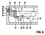
ロック機構24の機能が、図6及び図7における詳細な断面図により更に詳細に説明及び図示される。
The function of the
図6は、ロック機構24の係止又は係合状態を示す。そこでは、第1の係合部分32が、第2の係合部分48と解放可能で適合された接続状態にある。しかし、これらの例示的な説明においては、第1の係合部分32及び第2の係合部分48に対する参照だけがなされる。ロック機構24の作動により、特に係止要素26の作動により、すべての第1の係合部分28、30、32及び34が作動され、これにより、対応する第2の係合部分44、46、48及び50それぞれとの間で、解放可能な適合された接続状態、即ち係合状態にされることは言うまでもない。同じことは、前述の第1及び第2の係合部分の解放可能な適合された接続から係合していない状態へと向かう運動にも当てはまる。
FIG. 6 shows a locked or engaged state of the
第1の係合部分32及び第2の係合部分48の間の解放可能な適合された接続は、表面58を有する第1の係合部分32及び第2の表面60を有する第2の係合部分48により実現される。これらの表面58及び60は好ましくは、互いに平行に構成され、直接接触する。その結果、第2の収容部分16が第1の収容部分14上で強く保持される。
The releasable adapted connection between the
図6に示される係合状態において、第1及び第2の収容部分14及び16における任意の引力の結果として、係合部分32及び48に作用する力が、ピボット軸54に向けられる、又はこれを通る力ベクトルを生じさせることが更に好ましい。言い換えると、表面58及び60は、係合した状態にあるこれらの表面58及び60の直交ベクトルが、係止要素26のピボット軸54を通過するか又はこの軸の方へ向けられるような態様で方向付けられる。最後のケースは、前述したのと同一であると考えられることができる。なぜなら、これらの係合部分32及び48上に作用する力は、係合した状態にある表面58及び60に直交するベクトルにより表されることができるからである。
In the engaged state shown in FIG. 6, as a result of any attractive forces in the first and second receiving
ロック機構24の係合していない状態を実現するため、ハンドル56は、第2の収容部分16から遠ざけられなければならない。即ち図6及び図7の表現に対して下向きに移動される。これは、図6において矢印62により示される。これにより、ピボット軸54周りでの回転が生じ、第1の係合部分32だけでなく他のすべての第1の係合部分28、30及び34が、第2の係合部分48又は第2の係合部分44、46及び50との適合された接続から抜け出すよう移動する。図6及び図7の表現に関しては、第1の係合部分32は、左に、又は、ハウジング10に対して内向きに移動する。この離脱の終わりの状態が、図7の表現により示される。この係合していない状態において、第2の収容部分16は、第1の収容部分14から、容易に取り除かれることができる。
In order to achieve the disengaged state of the
係合又は係止状態が(再)確立される場合、ハンドル56は、第2の収容部分16の方へ、又は、図6及び図7の表現で言えば上方へ移動される。これは、矢印64により示される。これにより、ピボット軸54周りでの回転が再び発生する。その結果、第1の係合部分、例えば第1の係合部分32が、ハウジング10に対して外向きに、又は図7の表現で言えば右に移動される。これにより、第1の係合部分32は、第2の係合部分48と(再度)解放可能な適合された接続状態になる。
If the engaged or locked state is (re-) established, the
いずれかの方向にハンドル56が不必要な運動をしないよう、及び従って、第1の係合部分28、30、32及び34が不必要な開閉をしないよう、保持機構66が更に、第1の収容部分14に提供される。ハウジング10のこの特別な実施形態において、保持機構66は、取付要素36に構成される。保持機構66は、取付要素36に構成されるラッチ係合要素68と、ハンドル56に構成される鼻70とを有する。矢印62及び64により示されるハンドル56の運動方向において、鼻70は、ラッチ係合要素68の上を通過しなければならない。このラッチ係合要素68はバイアスされて、曲げられることができる。その結果、鼻70は、このラッチ係合要素68の上を通過することができる。このため、ラッチ係合要素68は、図6及び図7の表現で言えば右の方へ曲がる。鼻70がラッチ係合要素68を通過したあと、ラッチ係合要素68のバイアスが原因で、後者は、その前者の位置へと移動する。いずれの方向においてもハンドル56の不必要な運動が回避されつつ、ハンドル56を作動させることにより必要な運動が容易に実現されることができるよう、ラッチ係合要素68のバイアスは選択される。従って、この保持機構66は更に、ハウジング10の簡単で高速な開閉を支援する。
The retaining
図8及び図9は、本発明によるハウジング、即ちハウジング12の別の例示的な実施形態を示す。そこでは、ハウジング10に対するのと同じパーツが、同じ参照番号により示され、詳細な説明は省略される。
8 and 9 show another exemplary embodiment of a housing according to the present invention, ie
図10の断面図に示されるように、ハウジング12は、第1の収容部分86及び第2の収容部分96を有する。第1の収容部分86は、第1の内壁87を有し、第2の収容部分96は第2の内壁97を有する。更に、図8を参照すると、ハウジング12は、2つのタイプのロック機構である、ロック機構80及びロック機構82を有する。ロック機構タイプ80が、第1の収容部分86及び第2の収容部分96を接続するアセンブリ処理(これは、後ほどより詳細に説明される)において係止又は係合状態にされる一方、第2のロック機構82は好ましくは、第1の収容部分86及び第2の収容部分96のアセンブリ後、作動され、係止又は係合状態にされる。これは、ハウジング10のロック機構24に類似する。
As shown in the cross-sectional view of FIG. 10, the
また、図8に示されるように、ハウジング10同様、ハウジング12は、2つのロック機構82及び82'を有する。この場合も、それらのロック機構82及び82'は類似する要素を含む。その結果、ロック機構82の文脈のため及びこの文脈においてなされる以下の説明は、個別の図面に示されるロック機構82'に関しても対応して有効である。明確さのため、同じ参照番号は、同一の特徴に対して使用されるが、参照番号には、プライム記号(')が付加されることがある。
Further, as shown in FIG. 8, like the
更に、ロック機構24として、ロック機構82が、係合状態及び係合していない状態の間で変えられることができる。このため、ロック機構82は、係止要素84を有する。係止要素84は、この例では取付要素36を介してハウジング12の第1の収容部分86に構成される。第1の収容部分86に係止要素84を付けるためにハウジング12において同じ取付要素36が使用される場合であっても、この第1の収容部分86上に可動に係止要素84を付けるのに適した他の任意の取付要素又は取付方法が使用されることができることは言うまでもない。取付要素の選択は基本的に、個別の係止要素84の形状及び設計に依存する。
Further, as the
ハウジング12において、係止要素84は、前のピボット軸に対応する経路に沿って、即ち長手方向に移動可能である。言い換えると、係止要素84は、並進運動をすることが可能である。これは、図8及び図9において矢印88及び90により示される。簡単な作動のため、係止要素84は、ハンドル92を有する。このハンドル92は基本的に、係止要素26のハンドル56に対応する。係止要素84は更に、本実施形態において4つの第1の係合部分94を有する。
In the
第2の収容部分96(図8及び図9では特に示されない)は、第2の内壁97を有する。この内壁97に、第2の係合部分98が構成される。
The second receiving portion 96 (not specifically shown in FIGS. 8 and 9) has a second
図8は、第1の係合部分94及び第2の係合部分98の係合していない状態を示す。これは、第1の収容部分86及び第2の収容部分96が容易に分解されることができることを意味する。図8とは対照的に、図9は、係合した状態を示す。そこでは、第1の係合部分94が、この図で言えば、第2の係合部分98の上にある。これにより、係合部分94及び98の適合された接続が実現され、第1の収容部分86及び第2の収容部分96の分解は、不可能である。
FIG. 8 shows a state where the first engagement portion 94 and the second engagement portion 98 are not engaged. This means that the first receiving
図9に示されるように係合した状態を実現するため、係止要素84は、矢印88の方向において移動される。これは好ましくは、ハンドル92を用いて行われることができる。これにより、第1の係合部分94は、この方向において対応して移動され、対応する第2の係合部分98と係合する。
To achieve the engaged state as shown in FIG. 9, the locking element 84 is moved in the direction of the
図8に示されるように係合していない状態は、矢印90の方向における係止要素84の運動により、再び実現される。これは好ましくは、ハンドル92を用いることにより再度行われる。その結果、第1の係合部分94及び第2の係合部分98は係合しなくなり、ハウジング12の分解が可能となる。
The disengaged state as shown in FIG. 8 is realized again by the movement of the locking element 84 in the direction of the arrow 90. This is preferably done again by using the
第1の係合部分94及び第2の係合部分98の形状は例えば、第1の係合部分28、30、32及び34並びに第2の係合部分44、46、48及び50の形状とそれぞれ同一でありえる。しかしながら、第1及び第2の収容部分86及び96を信頼性高く係止することが実現される限り、これらの第1及び第2の係合部分94及び98に関して他の任意の適切な形状が選択されることができる。
The shape of the first engagement portion 94 and the second engagement portion 98 is, for example, the shape of the
図10は、図8の文脈において上述したロック機構80の単純な表現を示す。このロック機構80は、第3の係合部分を形成する舌100及び第4の係合部分を形成する溝102を有する。この特別な実施形態において、舌100は、第1の収容部分86の第1の内壁87に構成され、溝102は、第2の収容部分96の第2の内壁97に構成される。このロック機構80の係止状態は、可能であれば舌100が溝102に入るようわずかに曲げられた態様で、第1の収容部分86及び第2の収容部分96を接続することにより実現される。
FIG. 10 shows a simple representation of the
図8〜図10に示されるようにロック機構80とロック機構82とを持つ斯かる構成により、ハウジング12の2つの収容部分86及び96の均一に分散された係止が、3つの側で実現される。これは、2つの収容部分86及び96の均一に係止された状態及び信頼性が高い係止をもたらす。
As shown in FIGS. 8 to 10, such a configuration having a
作動可能なロック機構82の他に別のロック機構80を持つハウジング12だけが示されるが、図1〜図7においてハウジング10に関して示されるロック機構の実施形態は、ロック機構80と同一又は類似するロック機構を具備することもできることは言うまでもない。更に、この静的ロック機構80の他に、ハウジングは、ロック機構80の代わりに、又は、ハウジングの全ての可能な側に存在する作動可能なロック機構と共にでさえ、例えばロック機構24及び82といった別の作動可能なロック機構を具備することができる。
Although only the
本発明が図面及び前述の説明において詳細に図示され及び説明されたが、斯かる図示及び説明は、説明的又は例示的であると考えられ、本発明を限定するものではない。本発明は、開示された実施形態に限定されるものではない。図面、開示及び添付された請求項の研究から、開示された実施形態に対する他の変形が、請求項に記載の本発明を実施する当業者により理解され、実行されることができる。 While the invention has been illustrated and described in detail in the drawings and foregoing description, such illustration and description are to be considered illustrative or exemplary and not restrictive. The invention is not limited to the disclosed embodiments. From studying the drawings, disclosure and appended claims, other variations to the disclosed embodiments can be understood and implemented by those skilled in the art practicing the claimed invention.
請求項において、単語「有する」は他の要素又はステップを除外するものではなく、不定冠詞「a」又は「an」は複数性を除外するものではない。単一の要素又は他のユニットが、請求項に記載される複数のアイテムの機能を満たすことができる。特定の手段が相互に異なる従属項に記載されるという単なる事実は、これらの手段の組み合わせが有利に使用されることができないことを意味するものではない。 In the claims, the word “comprising” does not exclude other elements or steps, and the indefinite article “a” or “an” does not exclude a plurality. A single element or other unit may fulfill the functions of several items recited in the claims. The mere fact that certain measures are recited in mutually different dependent claims does not indicate that a combination of these measured cannot be used to advantage.
Claims (10)
第1の内壁を持つ少なくとも1つの第1の収容部分と、
第2の内壁を持つ少なくとも1つの第2の収容部分と、
少なくとも1つの係止要素とを有し、
前記少なくとも1つの係止要素が、少なくとも1つの経路に沿って少なくとも1つの第1の収容部分に移動可能に構成され、かつ前記第1の内壁に配置される複数の第1の係合部分を有し、
前記少なくとも1つの第2の収容部分は、前記第2の内壁に複数の第2の係合部分を有し、
前記第1の係合部分の各1つが、係合状態及び係合していない状態の間で少なくとも変化されることができる1つの対応する第2の係合部分との解放可能な適合された接続を形成し、
これらの少なくとも2つの状態の間の前記変化は、前記少なくとも1つの経路に沿って前記個別の係止要素を移動することにより、係止要素における前記第1の係合部分及び前記対応する第2の係合部分に対して同時に実現され、
前記少なくとも1つの経路が、前記少なくとも1つの係止要素の回転運動をもたらす、ハウジング。 A housing,
At least one first receiving portion having a first inner wall;
At least one second receiving portion having a second inner wall;
At least one locking element;
The at least one locking element is configured to be movable along at least one path to at least one first receiving portion, and includes a plurality of first engaging portions disposed on the first inner wall. Have
The at least one second receiving portion has a plurality of second engaging portions on the second inner wall;
Each one of the first engagement portions is releasably adapted with one corresponding second engagement portion that can be changed at least between an engaged state and an unengaged state. Form a connection,
The change between these at least two states is caused by moving the individual locking elements along the at least one path to cause the first engagement portion and the corresponding second in the locking elements. is realized at the same time against the engagement portion of,
The housing , wherein the at least one path provides rotational movement of the at least one locking element .
前記第2の収容部分の前記第2の内壁における少なくとも1つの第4の係合部分とを更に有し、
前記少なくとも1つの第3の係合部分及び前記少なくとも1つの第4の係合部分が、前記第2の収容部分と前記第1の収容部分を接続することにより確立される解放可能な適合された接続を形成する、請求項1に記載のハウジング。 At least one third engagement portion on the first inner wall of the first receiving portion;
And at least one fourth engaging portion on the second inner wall of the second receiving portion,
The at least one third engaging portion and the at least one fourth engaging portion are releasably adapted established by connecting the second receiving portion and the first receiving portion. The housing of claim 1 forming a connection.
請求項1乃至9の任意の一項に記載のハウジングとを有するモニタデバイス。 A display for presenting information;
A monitor device comprising the housing according to any one of claims 1 to 9 .
Applications Claiming Priority (3)
| Application Number | Priority Date | Filing Date | Title |
|---|---|---|---|
| US201261708725P | 2012-10-02 | 2012-10-02 | |
| US61/708,725 | 2012-10-02 | ||
| PCT/IB2013/058414 WO2014053926A1 (en) | 2012-10-02 | 2013-09-10 | Housing with releasable locking element |
Publications (3)
| Publication Number | Publication Date |
|---|---|
| JP2015534276A JP2015534276A (en) | 2015-11-26 |
| JP2015534276A5 JP2015534276A5 (en) | 2016-10-20 |
| JP6249535B2 true JP6249535B2 (en) | 2017-12-20 |
Family
ID=49713419
Family Applications (1)
| Application Number | Title | Priority Date | Filing Date |
|---|---|---|---|
| JP2015535126A Active JP6249535B2 (en) | 2012-10-02 | 2013-09-10 | Housing with removable locking element |
Country Status (6)
| Country | Link |
|---|---|
| US (1) | US9606575B2 (en) |
| EP (1) | EP2904885B1 (en) |
| JP (1) | JP6249535B2 (en) |
| CN (1) | CN104718805B (en) |
| BR (1) | BR112015007075A2 (en) |
| WO (1) | WO2014053926A1 (en) |
Families Citing this family (7)
| Publication number | Priority date | Publication date | Assignee | Title |
|---|---|---|---|---|
| JP6361623B2 (en) * | 2015-10-05 | 2018-07-25 | 株式会社デンソー | Fixing device |
| US9668371B1 (en) * | 2016-04-12 | 2017-05-30 | Dell Products L.P. | Systems and methods for securing panels to information handling system chassis |
| USD823264S1 (en) * | 2016-10-27 | 2018-07-17 | Universal Electronics Inc. | Remote control housing |
| USD825494S1 (en) * | 2016-10-27 | 2018-08-14 | Universal Electronics Inc. | Remote control housing |
| EP3648558A1 (en) | 2018-11-05 | 2020-05-06 | Koninklijke Philips N.V. | Housing with internal locking arrangement |
| JP6779342B1 (en) * | 2019-06-07 | 2020-11-04 | レノボ・シンガポール・プライベート・リミテッド | Housing for electronic devices and electronic devices |
| WO2023134870A1 (en) * | 2022-01-17 | 2023-07-20 | Huawei Technologies Co., Ltd. | Locking arrangement for smart device housing |
Family Cites Families (16)
| Publication number | Priority date | Publication date | Assignee | Title |
|---|---|---|---|---|
| US4077515A (en) | 1976-10-06 | 1978-03-07 | Dell Shoberg | Medical slide case with hinged molded sections |
| JPS62296U (en) * | 1985-06-12 | 1987-01-06 | ||
| IT1267973B1 (en) | 1994-01-13 | 1997-02-20 | Olivetti & Co Spa | BODYWORK FOR ELECTRONIC EQUIPMENT SUCH AS PERSONAL COMPUTERS AND / OR THEIR PERIPHERALS |
| JP3338739B2 (en) * | 1995-05-12 | 2002-10-28 | アンリツ株式会社 | Electromagnetic wave shielding box |
| US6440076B1 (en) | 2000-11-09 | 2002-08-27 | Koninklijke Philips Electronics N.V. | Ultrasound transducer connector assembly |
| US7609512B2 (en) * | 2001-11-19 | 2009-10-27 | Otter Products, Llc | Protective enclosure for electronic device |
| US7924553B2 (en) * | 2005-03-09 | 2011-04-12 | Hewlett-Packard Development Company, L.P. | Computer device locking system |
| US7349199B2 (en) * | 2005-06-17 | 2008-03-25 | Hewlett-Packard Development Company, L.P. | Computer device display protector |
| CN2842533Y (en) * | 2005-06-22 | 2006-11-29 | 鸿富锦精密工业(深圳)有限公司 | Computer cover locking device |
| CN101873777B (en) * | 2009-04-27 | 2014-11-05 | 鸿富锦精密工业(深圳)有限公司 | Case |
| CN101932216A (en) | 2009-06-18 | 2010-12-29 | 鸿富锦精密工业(深圳)有限公司 | Door closure device |
| US8074390B2 (en) | 2009-07-06 | 2011-12-13 | Michele Trevison Rain | Display box |
| US8233272B2 (en) | 2009-08-25 | 2012-07-31 | Mindray Ds Usa, Inc. | Display units for use in monitoring patients and related systems and methods |
| JP2011091078A (en) * | 2009-10-20 | 2011-05-06 | Nec Corp | Connection structure of housing |
| EP2637738A1 (en) | 2010-11-11 | 2013-09-18 | Koninklijke Philips Electronics N.V. | Carrying case with improved access for defibrillator and accessories |
| CN103404116B (en) * | 2011-02-24 | 2015-12-02 | 日本电气株式会社 | Electronic installation |
-
2013
- 2013-09-10 EP EP13799674.0A patent/EP2904885B1/en active Active
- 2013-09-10 US US14/432,493 patent/US9606575B2/en active Active
- 2013-09-10 CN CN201380051901.7A patent/CN104718805B/en active Active
- 2013-09-10 WO PCT/IB2013/058414 patent/WO2014053926A1/en active Application Filing
- 2013-09-10 BR BR112015007075A patent/BR112015007075A2/en not_active Application Discontinuation
- 2013-09-10 JP JP2015535126A patent/JP6249535B2/en active Active
Also Published As
| Publication number | Publication date |
|---|---|
| CN104718805A (en) | 2015-06-17 |
| US9606575B2 (en) | 2017-03-28 |
| WO2014053926A1 (en) | 2014-04-10 |
| CN104718805B (en) | 2017-09-15 |
| BR112015007075A2 (en) | 2017-07-04 |
| EP2904885B1 (en) | 2017-07-12 |
| US20150277487A1 (en) | 2015-10-01 |
| EP2904885A1 (en) | 2015-08-12 |
| JP2015534276A (en) | 2015-11-26 |
Similar Documents
| Publication | Publication Date | Title |
|---|---|---|
| JP6249535B2 (en) | Housing with removable locking element | |
| JP6382985B2 (en) | Pivot cable solutions | |
| JP4233587B2 (en) | Actuating mechanism and pressurizing device for fluid displacement | |
| US9851037B2 (en) | Fluid connector and method for making sealed fluid connections | |
| US9629522B2 (en) | Separable medical instrument, and operated section and operating section thereof | |
| CN110049787A (en) | For attachment to be fixed to the interconnecting piece of sterile chamber | |
| JP6506025B2 (en) | User replaceable filter for gas sampling system | |
| US11471233B2 (en) | Preloaded sterile bag | |
| JP5942051B2 (en) | Endoscope | |
| JP2018519062A (en) | Surgical grip with a rotating fixed unit internally biased by a spring | |
| US10265233B2 (en) | Incubator | |
| EP3192483B1 (en) | Incubator | |
| JP2018535519A (en) | Lighting fixture with detachable handle | |
| JP2004267764A (en) | Rack with worktable | |
| CN216317969U (en) | Endoscope quick-change clamping and rotating device and minimally invasive surgery robot | |
| JP6013590B2 (en) | Electronic thermometer storage case | |
| CN107260115B (en) | Vaginal speculum with connecting ring | |
| CN112970339B (en) | Housing with internal locking means | |
| JP2016168220A (en) | Angle operation device of endoscope | |
| JP2006257651A (en) | Flat push-pull lever body structure | |
| JP3665538B2 (en) | Endoscope operation device | |
| CN115721246A (en) | Endoscope transmission device and surgical robot | |
| JPH10118020A (en) | Waterproof cap for electric connector of celoscope | |
| JP2005161079A (en) | Treating instrument retainer and hanger support for mounting retainer | |
| EP4266967A1 (en) | Control device and rotary knob assembly for a steerable medical device |
Legal Events
| Date | Code | Title | Description |
|---|---|---|---|
| A521 | Request for written amendment filed |
Free format text: JAPANESE INTERMEDIATE CODE: A523 Effective date: 20160830 |
|
| A621 | Written request for application examination |
Free format text: JAPANESE INTERMEDIATE CODE: A621 Effective date: 20160830 |
|
| RD04 | Notification of resignation of power of attorney |
Free format text: JAPANESE INTERMEDIATE CODE: A7424 Effective date: 20170214 |
|
| A871 | Explanation of circumstances concerning accelerated examination |
Free format text: JAPANESE INTERMEDIATE CODE: A871 Effective date: 20170321 |
|
| A975 | Report on accelerated examination |
Free format text: JAPANESE INTERMEDIATE CODE: A971005 Effective date: 20170609 |
|
| A131 | Notification of reasons for refusal |
Free format text: JAPANESE INTERMEDIATE CODE: A131 Effective date: 20170615 |
|
| TRDD | Decision of grant or rejection written | ||
| A01 | Written decision to grant a patent or to grant a registration (utility model) |
Free format text: JAPANESE INTERMEDIATE CODE: A01 Effective date: 20171116 |
|
| A61 | First payment of annual fees (during grant procedure) |
Free format text: JAPANESE INTERMEDIATE CODE: A61 Effective date: 20171117 |
|
| R150 | Certificate of patent or registration of utility model |
Ref document number: 6249535 Country of ref document: JP Free format text: JAPANESE INTERMEDIATE CODE: R150 |
|
| R250 | Receipt of annual fees |
Free format text: JAPANESE INTERMEDIATE CODE: R250 |
|
| R250 | Receipt of annual fees |
Free format text: JAPANESE INTERMEDIATE CODE: R250 |
|
| R250 | Receipt of annual fees |
Free format text: JAPANESE INTERMEDIATE CODE: R250 |
|
| R250 | Receipt of annual fees |
Free format text: JAPANESE INTERMEDIATE CODE: R250 |